Embed Size (px)
Citation preview
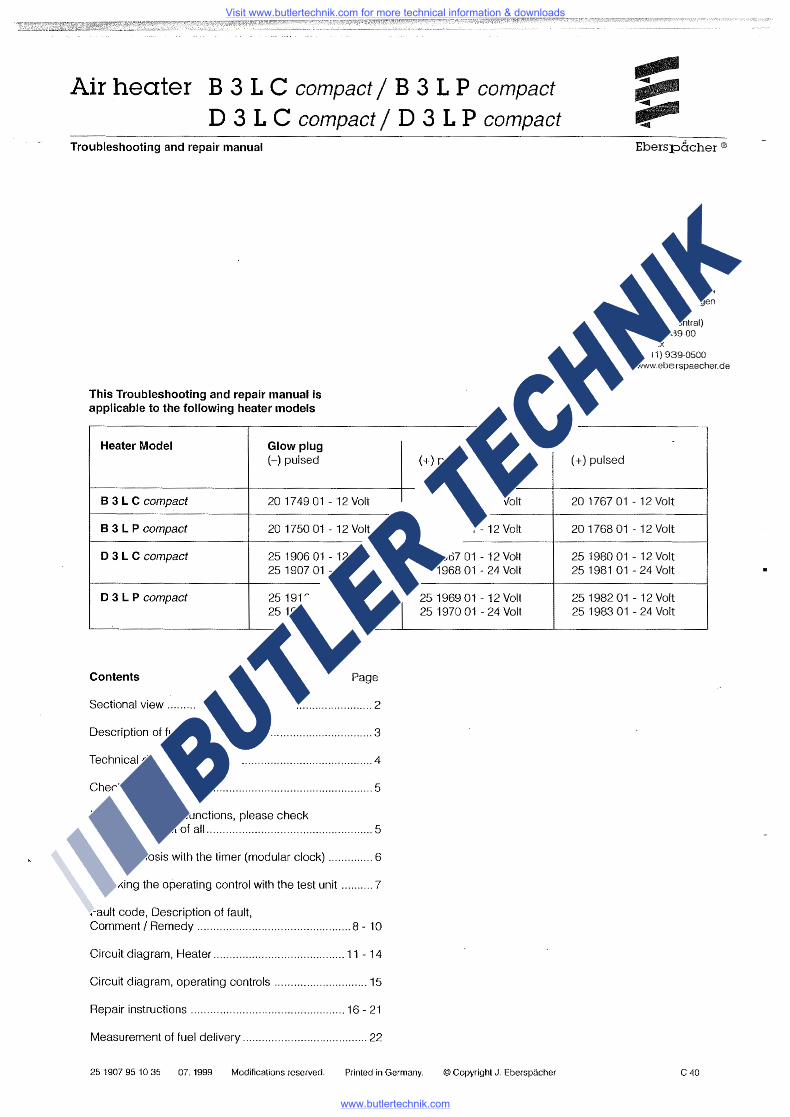
Air heater B 3 L C compact/ B 3 L P compact D 3 L C compact/ D 3 L P compact
Troubleshooting and repair manual
This Troubleshooting and repair manual is applicable to the following heater models
Heater Model Glow plug (-)pulsed
8 3 L C compact 20 17 49 01 - 12 Volt
8 3 L P compact 20 1750 01 - 12 Volt
D 3 L C compact 25 1906 01 - 12 Volt 25 1907 01 - 24 Volt
D 3 L P compact 25 1912 01 - 12 Volt 25 1913 01 - 24 Volt
Contents Page
Sectional view ................................................................ 2
Description of function ................................................... 3
Technical data ................................................................ 4
Check values ................................................................. 5
In the event of malfunctions, please check the following first of all .................................................... 5
Fault diagnosis with the timer (modular clock) .............. 6
Checking the operating control with the test unit .......... 7
Fault code, Description of fault, Comment I Remedy ................................................ 8 - 10
Circuit diagram, Heater ......................................... 11 - 14
Circuit diagram, operating controls ............................. 15
Repair instructions ................................................ 16 - 21
Measurement of fuel delivery ....................................... 22
( +) pulsed I current regulator
20 1762 01 -12 Volt
20 1763 01 - 12 Volt
25 1967 01 - 12 Volt 25 1968 01 - 24 Volt
25 1969 01 - 12 Volt 25 1970 01 - 24 Volt
25 1907 95 10 35 07. 1999 Modifications reserved. Printed in Germany. ©Copyright J. Eberspacher
(+)pulsed
Eberspacher®
J. Eberspacher GmbH & Co. Eberspacherstr. 24 D-73730 Esslingen
Telefon (zentral) (0711) 939-00 Telefax (0711) 939-0500 www. ebe rspaecher. de
20 1767 01 - 12 Volt
20 1768 01 - 12 Volt
25 1980 01 - 12 Volt 25 1981 01 - 24 Volt
25 1982 01 - 12 Volt 25 1983 01 - 24 Vo!t
c 40
Visit www.butlertechnik.com for more technical information & downloads
www.butlertechnik.com
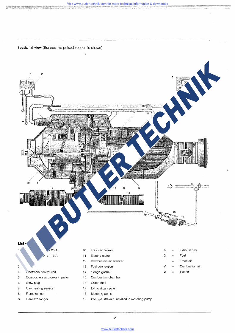
Sectional view (the positive pulsed version is shown)
2
9
~=====
List of Parts
Main fuse 12 V - 25 A 10 Fresh air blower A Exhaust gas
24 V - 15 A 11 Electric motor 8 Fuel
2 Fuse 5 A 12 Combustion air silencer F Fresh air
3 Timer 13 Fuel connection v Combustion air
4 Electronic control unit 14 Flange gasket w Hot air
5 Combustion air blower impeller 15 Combustion chamber
6 Glow plug 16 Outer shell
7 Overheating sensor 17 Exhaust gas pipe
8 Flame sensor 18 Metering pump
9 Heat exchanger 19 Pot-type strainer, installed in metering pump
2
Visit www.butlertechnik.com for more technical information & downloads
www.butlertechnik.com
Description of function
Switch-on
When switched on, the operation indicator or the green pilot light will illuminate. The glow plug is switched on. The blower will start up and rotate slowly.
Note: If residual heat is still present in the heat exchanger, only the blower will operate (cold air). When the residual heat has been dissipated, the starting process will commence.
Starting process
After approximately 35 seconds, fuel delivery will take place. The fuel/air mixture will ignite. The blower and the fuel delivery will be increased progressively. After flame detection and stabilization of combustion, the glow plug will be switched off.
Rapid heating up of the heater takes place on the POWER setting with maximum heat flow until the heat exchanger has reached its operating temperature.
Note: The period of operation on POWER setting with maximum heat flow is temperature-dependent.
Regulation in Heating mode
In Heating mode, the ambient temperature or the temperature of the heating air drawn in is measured continuously and compared with the setpoint temperature set on the operating control. If the operating temperature of the heating air drawn in is higher than the required ambient temperature, the heater will switch to LOW setting and will then continue with the blower motor rotating at low RPM. If the heat flow on LOW setting is insufficient, the heater will switch to MEDIUM setting. The blower will continue with the blower motor rotating at low RPM. In most cases, LOW-MEDIUM-LOW regulation at low RPM will supply the heat required. If the heat flow on MEDIUM setting is insufficient, the heater will revert to the HIGH setting. This will then entail the blower motor running at full RPM. If, in special cases, even less heat flow should be required than the heater supplies on the LOW setting, the heater will switch to the OFF setting. After controlled after-running, constant after-ventilation will take place at minimum blower speed (only in Air Circulation mode), until Restart takes place.
Restart takes place on MEDIUM setting with the blower motor running at low RPM.
3
Switch-off
When the heater is switched off, the operation indicator or the green pilot light and the fuel delivery wi!I switch off. After-running of the blower will take place to cool the heater down. The glow plug will switch on for 30 seconds during afterrunning in order to clean out combustion residues.
Note: If there is still no fuel delivery during the starting process, or if the heater is set to OFF, the heater will be shut down immediately without after-running.
Control and safety features
The flame is monitored by the flame sensor, and the maximum permissible operating temperature by the overheating sensor. Both these features influence the control unit. which switches the heater off in the event of a malfunction.
If the voltage (according to Model) drops below approximately 10.5 or 21 volts, or rises above approximately 15.9 or 31.8 volts, malfunction shutoff will take place.
In the case of a defective glow plug and/or break in the electric supply lead to the metering pump, the heater will not start.
The speed of rotation of the blower motor is monitored continuously. If the blower motor fails to start up, or if its RPM deviates by more than 10 %, the heater will go to malfunction mode after 30 seconds.
Please note!
When carrying out electric welding on the vehicle, for protection of the control unit the positive pole of the battery should be disconnected and the lead connected to chassis.
Visit www.butlertechnik.com for more technical information & downloads
www.butlertechnik.com
Technical Data
Heating medium
Heat flow setting
Fuel
Heat flow1)
83LC compact I 03LC compact 83LP compact I 03LP compact
Heat throughput w/o back-pressure 1)
83LC compact I D3LC compact B3LP compact I D3LP compact
Fuel consumption i} 83LC compact B3LP compact 03LC compact 03LP compact
Nominal voltage
Operating range
Lower voltage limit An undervoltage protection installed in the control unit shuts
the heater off when the voltage limit is undershot
Upper voltage limit An overvoltage protection installed in the control unit shuts
the heater off when the voltage limit is exceeded.
Values in brackets apply to when the glow plug is switched on. The voltage values must be present for longer than 20 seconds.
Electrical power consumption 1)
B3LC compact I 03LC compact B3LP compact I 03LP compact
03LC compact D3LP compact
B3LC compact I D3LC compact B3LP compact I D3LP compact
Interference suppression
Weight
Ambient temperature
Heater in operation Heater out of operation Metering pump in operation
I) at nominal voltage all data± 10 % 4
Air
Power I High I Medium I Low I Off
Petrol - commercial grade Diesel - commercial grade
Power High 3500 3200 3000 2500
160 160 140 130
0,47 0,42 0,40 0,34 0,42 0,37 0,36 0,30
12 volts
10 to 14 volts
10,5 volts (9,5 V)
15,9 volts (15,2 V)
at start
12 v = 270 w 12 v = 260 w 24 V = 240W 24 V = 230W
in operation
Power 36 26
High 36 22
Medium Low 1500 1000 w 1500 900W
80 65 kg/h 85 60 kg/h
0,20 0,13 l/h 0,20 0,121/h 0,18 0,121/h 0,18 0, 11 l/h
24 volts
20 to 28 volts
21 volts (19 V)
31,8 volts (30,4 V)
Medium 12 15
Low 8W 8W
3, additional suppression measures possible
approx. 6 kg
03LC compact D3LP compact
-40 °C to +70 °C -40 °C to +85 °C -40 °C to +50 °C
B3LC compact B3LP compact
-40 °C to +50 °C -40 °C to +85 °C -40 °C to +20 °C
Visit www.butlertechnik.com for more technical information & downloads
www.butlertechnik.com
Check values
Motor speed B3LC compact D3LC compact
4200 RPM 4200 RPM 2200 RPM 1800 RPM
B3LP compact D3LP compact
3500 RPM 3200 RPM 2200 RPM 1600 RPM
•Power •High •Medium •Low •Settling 1000 RPM with internal temperature sensor
0 RPM with external temperature sensor
Resistance values
Metering pump 12 volt Metering pump 24 volt Glow plug 12 volt Glow plug 24 volt
approx. 10 Q
approx. 36 Q
approx. 0.6 Q
approx. 2 Q
Operating control I setpoint pot. 1740 - 2180 Q (±80 Q)
In
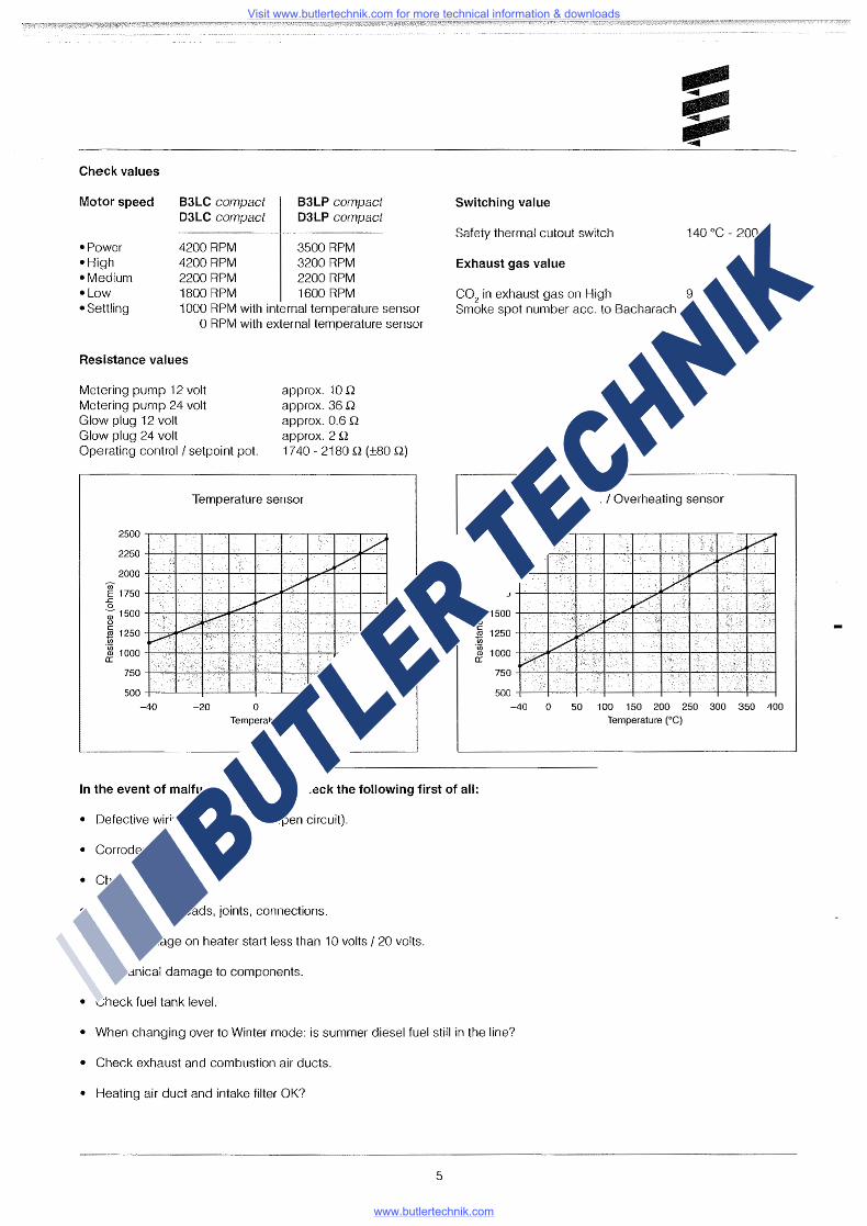
Temperature sensor
2500.--.----.-..,.....---r----.---.-----.~-.---~
2250 -+-----'-+---4--'-----+-'"--~--+-~+---4---'-~'--,__.
2000 -t----'-'t-----t--+-':---+---'---t-f--~~-'----+---'--i
E 1750-+--"-+---4--+--~~~'--+------4----1--~ ..c 0 -;1soo+c---;--,,+-:--"-l~-7t~.,..;-.;_;_--+":~+-'"-'--l1---+~-1 (.)
~ 1250+-~~...,-.j~+;-:-'-'-~,....,..-,,,f-_,_.1--~~...,.,.+......,.,,,._,,..i If) £ 1000-;-,,-~~-'-ll--~~...:.+:-:,_.;.-;---1-'----"'--'t--'--':---'-ll----"~---:-'-:.J
750-t----'f-"-"~~,..,.--r----T-'.'-,.--t-~~-,-f-....,.-+-----,--,~
500-+--...__--t--L--~-"'-'------'+-----'-----+--~
-40 -20 0 20 40 Temperature (°C)
Switching value
Safety thermal cutout switch 140 °C - 200 °C
Exhaust gas value
C02
in exhaust gas on High 9 - 11 Vol. % Smoke spot number acc. to Bacharach ~ 4
©
Flame sensor I Overheating sensor
2500~-~-~-~-~~-~-~-~-~
2250-+-'--+:'-~+-,-t---,.:..,1--~_;_+-t-~-7-c:.+~"'--1
2000 -+----+---+--~0-------1----..,.-+-...,..-,, _ __,... _ __,..._ _ __.
E 1750 +-'--+-:---.;t--..;__,..~---,-;i-'---~'--~---t---'---t-~rl ..c 0 -; 1500 -+-----~-,r-,-,..,--,-r-:;;.....--;r-~...,---.~---+.....,,..---t-~__, (.) c ~ 1250
·~ 1000 --t-="'F-:-....':..,-r--.,....,.......,.r-~r--.,-,...,----t"""""'T"""7-i"---+~--t-,..,--':--t a:
750-+---'...'-'--,-+-"'-'-+-"~+---,-.if----..,'--l~~--1-~----+-'---"'""'-I
500-+-~-+-'-+-~t----if----..,--t----+--+---t-~__,
-40 0 50 100 150 200 250 300 350 400 Temperature (0 C)
In the event of malfunctions, please check the following first of all:
• Defective wiring (short-circuits, open circuit).
• Corroded contacts.
• Check fuses.
• Check electric leads, joints, connections.
• Battery voltage on heater start less than 1 O volts I 20 volts.
• Mechanical damage to components.
• Check fuel tank level.
• When changing over to Winter mode: is summer diesel fuel still in the line?
• Check exhaust and combustion air ducts.
• Heating air duct and intake filter OK?
5
Visit www.butlertechnik.com for more technical information & downloads
www.butlertechnik.com
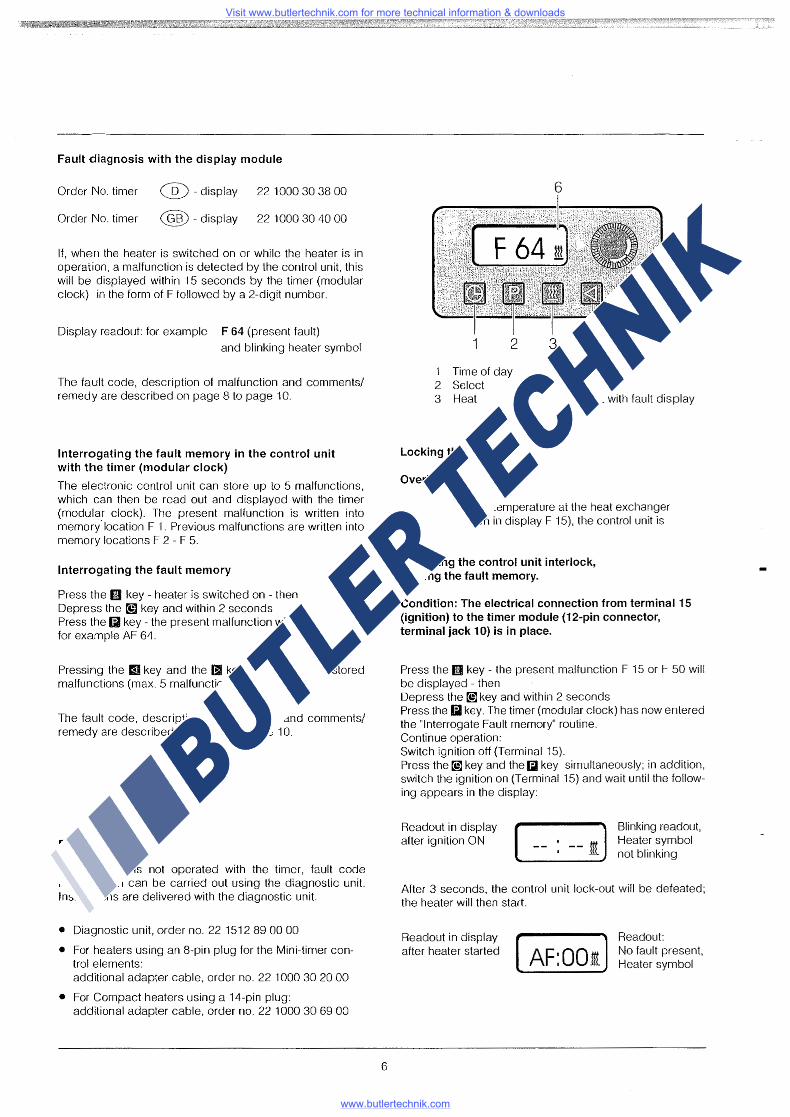
Fault diagnosis with the display module
Order No. timer @ -display 221000 30 38 00
Order No. timer @-display 22 1000 30 40 00
If, when the heater is switched on or while the heater is in operation, a malfunction is detected by the control unit, this will be displayed within 15 seconds by the timer (modular clock) in the form of F followed by a 2-digit number.
Display readout: for example F 64 (present fault)
and blinking heater symbol
The fault code, description of malfunction and comments/ remedy are described on page 8 to page 10.
Interrogating the fault memory in the control unit with the timer (modular clock)
The electronic control unit can store up to 5 malfunctions, which can then be read out and displayed with the timer (modular clock). The present malfunction is written into memory' location F 1. Previous malfunctions are written into memory locations F 2 - F 5.
Interrogating the fault memory
Press the l!!I key - heater is switched on - then Depress the@] key and within 2 seconds Press the Ii) key - the present malfunction will be displayed, for example AF 64.
Pressing the II key and the II key will call up the stored malfunctions (max. 5 malfunctions).
The fault code, description of malfunction and comments/ remedy are described on page 8 to page 10.
Please note!
If the heater is not operated with the timer, fault code interrogation can be carried out using the diagnostic unit. Instructions are delivered with the diagnostic unit
• Diagnostic unit, order no. 22 1512 89 00 00
• For heaters using an 8-pin plug for the Mini-timer control elements: additional adapter cable, order no. 22 1000 30 20 00
• For Compact heaters using a 14-pin plug: additional adapter cable, order no. 22 1000 30 69 00
6
1 2
1 Time of day 2 Select
6
3 4
4 Reverse 5 Forward
5
3 Heat 6 Readout with fault display
Locking the control unit
Overheating
In case of excess temperature at the heat exchanger (error 013, shown in display F 15), the control unit is locked.
Canceling the control unit interlock, erasing the fault memory.
Condition: The electrical connection from terminal 15 (ignition) to the timer module (12-pin connector, terminal jack 10) is in place.
Press the flll key - the present malfunction F 15 or F 50 will be displayed - then Depress the @]key and within 2 seconds Press the Iii key. The timer (modular clock) has now entered the "Interrogate Fault memory" routine. Continue operation: Switch ignition off (Terminal 15). Press the@] key and the Iii key simultaneously; in addition, switch the ignition on (Terminal 15) and wait until the following appears in the display:
Readout in display after ignition ON ( -- -- I] Blinking readout,
Heater symbol not blinking
After 3 seconds, the control unit lock-out will be defeated; the heater will then start
Readout in display after heater started ( AF:001]
Readout: No fa ult present, Heater symbol
Visit www.butlertechnik.com for more technical information & downloads
www.butlertechnik.com
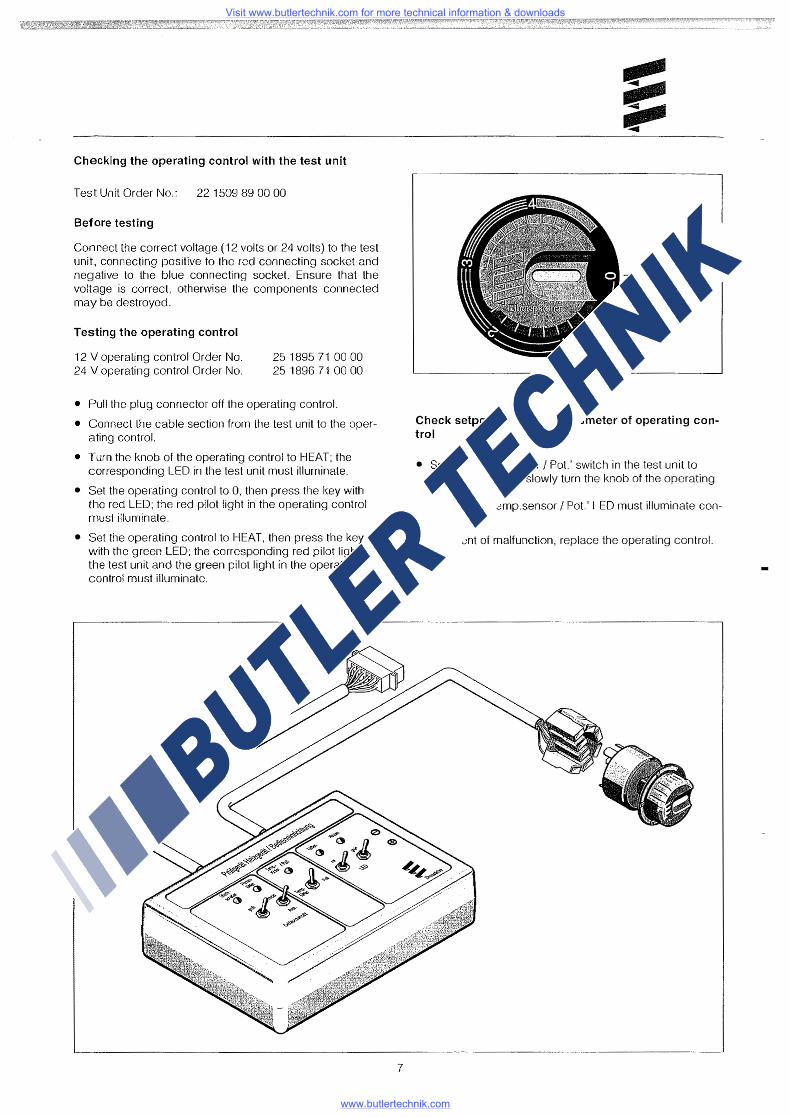
Checking the operating control with the test unit
Test Unit Order No.: 22 1509 89 00 00
Before testing
Connect the correct voltage (12 volts or 24 volts) to the test unit, connecting positive to the red connecting socket and negative to the blue connecting socket. Ensure that the voltage is correct, otherwise the components connected may be destroyed.
Testing the operating control
12 V operating control Order No. 24 V operating control Order No.
25 1895 71 00 00 25 1896 71 00 00
• Pull the plug connector off the operating control.
• Connect the cable section from the test unit to the operating control.
• Turn the knob of the operating control to HEAT; the corresponding LED in the test unit must illuminate.
• Set the operating control to 0, then press the key with the red LED; the red pilot light in the operating control must illuminate.
• Set the operating control to HEAT, then press the key with the green LED; the corresponding red pilot light in the test unit and the green pilot light in the operating control must illuminate.
7
-- OFF
Heat
Check setpoint value potentiometer of operating control
• Set the 'Temp.sensor I Pot' switch in the test unit to 'Pot.' Position and slowly turn the knob of the operating control. The green 'Temp.sensor I Pot' LED must illuminate continuously.
In the event of malfunction, replace the operating control.
Visit www.butlertechnik.com for more technical information & downloads
www.butlertechnik.com
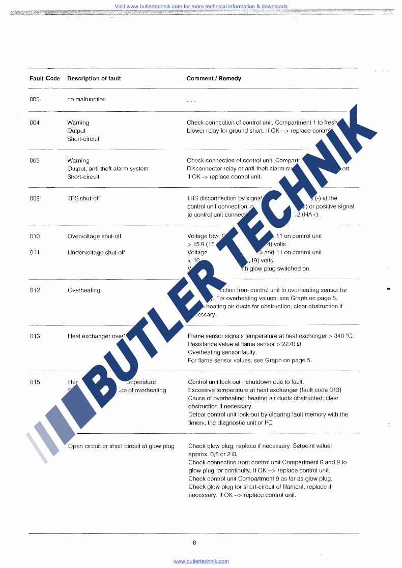
Fault Code Description of fault
000
004
005
009
010
011
012
013
015
020
no malfunction
Warning
Output Short-circuit
Warning Output, anti-theft alarm system
Short-circuit
TRS shut-off
Overvoltage shut-off
Undervoltage shut-off
Overheating
Heat exchanger overtemperature
Heat exchanger overtemperature Excessive occurrence of overheating
Open circuit or short circuit at glow plug
Comment I Remedy
Check connection of control unit, Compartment 1 to fresh air
blower relay for ground short. If OK--> replace control unit.
Check connection of control unit, Compartment 2 to elec. Disconnector relay or anti-theft alarm system for ground short.
If OK -> replace control unit.
TRS disconnection by signal change from ( +) to (-) at the control unit connection, compartment 10 (D+) or positive signal to control unit connection, compartment 12 {HA+).
Voltage btw. Compartment 5 and 11 on control unit
> 15.9 (15.2) volts or 31.8 (30.4) volts. Voltage btw. Compartment 5 and 11 on control unit
< 10.5 (9.5) volts or 21 (19) volts.
Values in brackets with glow plug switched on.
Check connection from control unit to overheating sensor for
continuity. For overheating values, see Graph on page 5. Check heating air ducts for obstruction; clear obstruction if
necessary.
Flame sensor signals temperature at heat exchanger> 340 °C. Resistance value at flame sensor > 2270 Q
Overheating sensor faulty. For flame sensor values, see Graph on page 5.
Control unit lock out - shutdown due to fault. Excessive temperature at heat exchanger (fault code 013)
Cause of overheating: heating air ducts obstructed; clear
obstruction if necessary. Defeat control unit lock-out by clearing fault memory with the
timerv, the diagnostic unit or PC
Check glow plug, replace if necessary. Setpoint value:
approx. 0,6 or 2 Q
Check connection from control unit Compartment 6 and 9 to
glow plug for continuity. If OK--> replace control unit.
Check control unit Compartment 9 as far as glow plug. Check glow plug for short-circuit of filament, replace if necessary. If OK--> replace control unit.
8
Visit www.butlertechnik.com for more technical information & downloads
www.butlertechnik.com
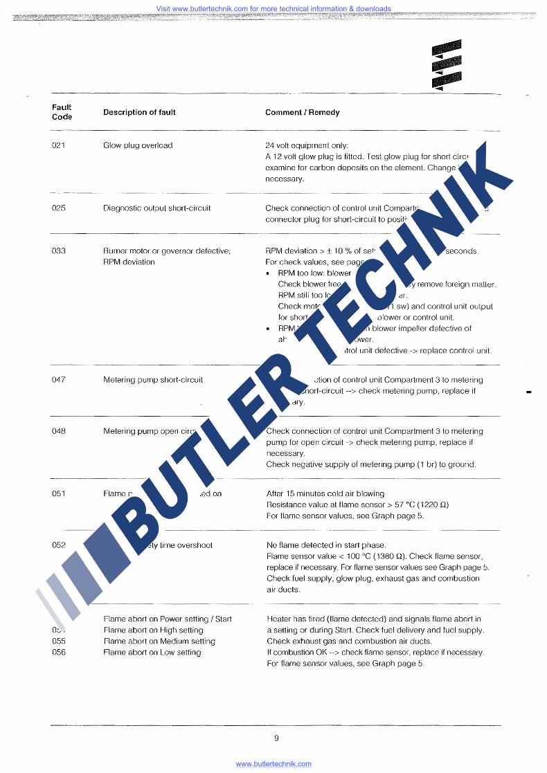
Fault Code
021
025
033
047
048
051
052
053 054 055 056
Description of fault
Glow plug overload
Diagnostic output short-circuit
Burner motor or governor defective;
RPM deviation
Metering pump short-circuit
Metering pump open circuit
Flame present when switched on
No start, sat ety time overshoot
Flame abort on Power setting I Start
Flame abort on High setting
Flame abort on Medium setting
Flame abort on Low setting
Comment I Remedy
24 volt equipment only:
A 12 volt glow plug is fitted. Test glow plug for short circuit or
examine for carbon deposits on the element. Change if necessary.
Check connection of control unit Compartment 4 to diagnostic
connector plug for short-circuit to positive.
RPM deviation > ± 10 % of setpoint value for > 30 seconds.
For check values, see page 5.
• RPM too low: blower obstructed.
Check blower free-running, if necessary remove foreign matter.
RPM still too low--> replace blower.
Check motor supply lead (1 br/1 sw) and control unit output
for short-circuit--> replace blower or control unit.
• RPM too high: solenoid in blower impeller defective of
absent--> replace blower.
RPM sensor in control unit defective-> replace control unit.
Check connection of control unit Compartment 3 to metering
pump for short-circuit--> check metering pump, replace if necessary.
Check connection of control unit Compartment 3 to metering
pump for open circuit-> check metering pump, replace if necessary.
Check negative supply of metering pump (1 br) to ground.
After 15 minutes cold air blowing
Resistance value at flame sensor > 57 °C ( 1220 .Q)
For flame sensor values, see Graph page 5.
No flame detected in start phase.
Flame sensor value< 100 °C (1380 Q). Check flame sensor,
replace if necessary. For flame sensor values see Graph page 5.
Check fuel supply, glow plug, exhaust gas and combustion
air ducts.
Heater has fired (flame detected) and signals flame abort in
a setting or during Start. Check fuel delivery and fuel supply.
Check exhaust gas and combustion air ducts.
If combustion OK--> check flame sensor, replace if necessary.
For flame sensor values, see Graph page 5.
9
Visit www.butlertechnik.com for more technical information & downloads
www.butlertechnik.com
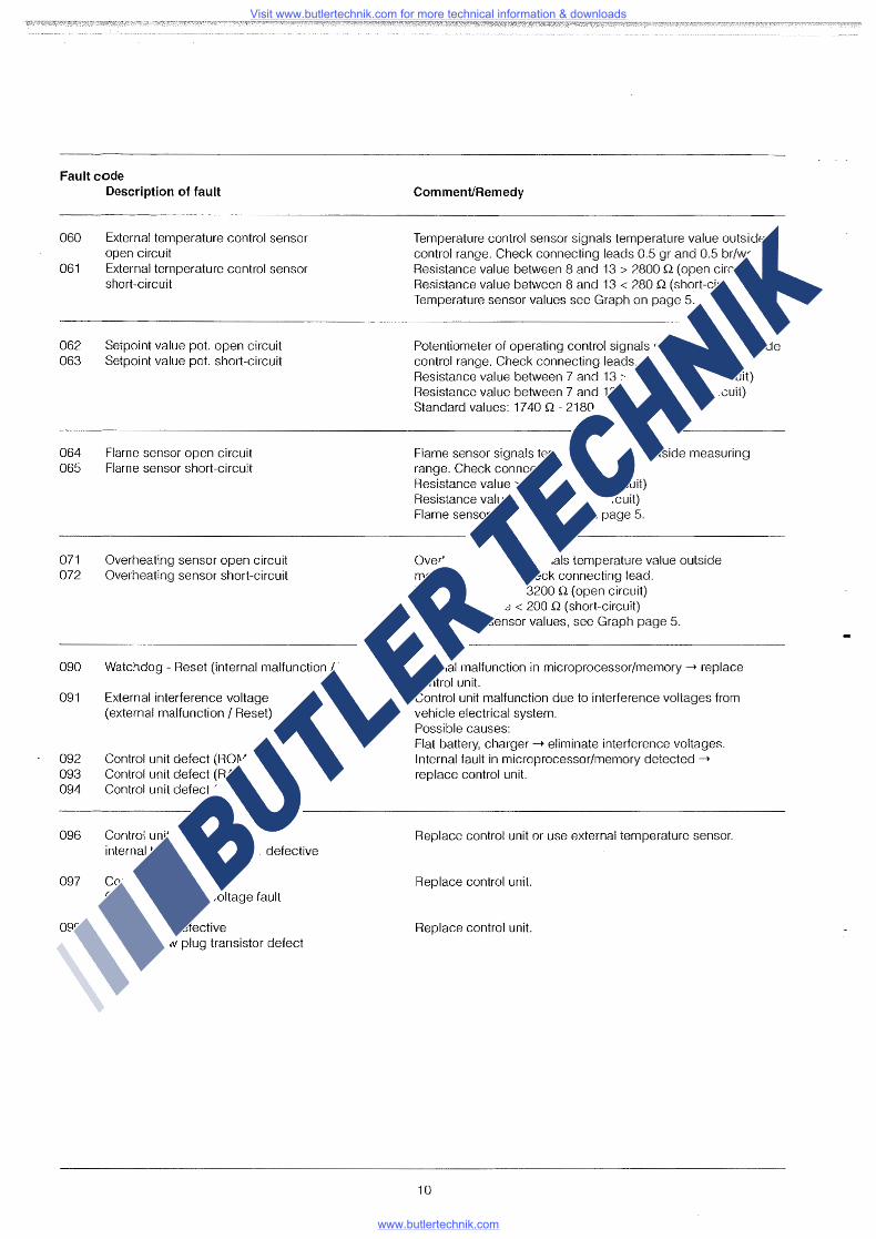
Fault code
060
061
062 063
064 065
071 072
090
091
092 093 094
096
097
099
Description of fault
External temperature control sensor open circuit External temperature control sensor short-circuit
Setpoint value pot. open circuit Setpoint value pot. short-circuit
Flame sensor open circuit Flame sensor short-circuit
Overheating sensor open circuit Overheating sensor short-circuit
Watchdog - Reset (internal malfunction I Reset)
External interference voltage (external malfunction I Reset)
Control unit defect {ROM fault} Control unit defect {RAM fault) Control unit defect {EEPROM fault)
Control unit defective internal temperature sensor defective
Control unit defective Oscillator or undervoltage fault
Control unit defective internal glow plug transistor defect
Comment/Remedy
Temperature control sensor signals temperature value outside control range. Check connecting leads 0.5 gr and 0.5 br/ws. Resistance value between 8 and 13 > 2800 Q (open circuit) Resistance value between 8 and 13 < 280 Q (short-circuit) Temperature sensor values see Graph on page 5.
Potentiometer of operating control signals setpoint value outside control range. Check connecting leads. Resistance value between 7 and 13 > 2800 Q (open circuit) Resistance value between 7 and 13 < 280 Q (short-circuit) Standard values: 1740 Q - 2180 Q (±80 Q)
Flame sensor signals temperature value outside measuring range. Check connecting leads. Resistance value> 3200 Q (open circuit) Resistance value< 200 Q (short-circuit) Flame sensor values, see Graph page 5.
Overheating sensor signals temperature value outside measuring range. Check connecting lead. Resistance value> 3200 Q (open circuit) Resistance value< 200 Q (short-circuit) Overheating sensor values, see Graph page 5.
Internal malfunction in microprocessor/memory -t replace control unit. Control unit malfunction due to interference voltages from vehicle electrical system. Possible causes: Flat battery, charger -+ eliminate interference voltages. Internal fault in microprocessor/memory detected -t
replace control unit.
Replace control unit or use external temperature sensor.
Replace control unit.
Replace control unit.
10
Visit www.butlertechnik.com for more technical information & downloads
www.butlertechnik.com
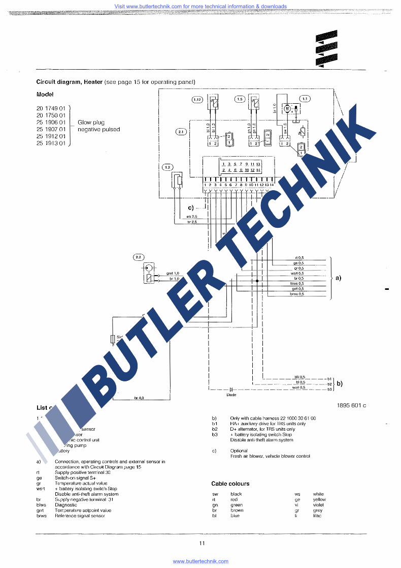
Circuit diagram, Heater (see page 15 for operating panel)
Model
20 1749 01 20 1750 01 25 1906 01 25 1907 01 25 1912 01 25 1913 01
Glow plug negative pulsed
List of parts
1.1 1.2 1.5 1.12 2.1 2.2 5.1
Burner motor Glow plug Overheating sensor Flame sensor Electronic control unit Metering pump Battery
rt4,0
br4,0
a) Connection. operating controls and external sensor in accordance with Circuit Diagram page 15
rt Supply positive terminal 30 ge Switch-on signal S+ gr Temperature actual value wsrt + battery isolating switch Slop
Disable anti-theft alarm system br Supply negative terminal 31 blws Diagnostic grrl Temperature selpoint value brws Reference signal sensor
11
rt0,5
ge0,5
gr0,5
a)
I I 1 grrt0,5
I I J brws0,5
I I I I I I I I I l l ! I I I I I I I I I I I I I I I I I I I I I I I I I L ____ ~li0,5 ____ b1}
I ___ Ct- __ ~--=---=---=-----=--ws~ ~:!-_-=_ ~ :~ b)
b) b1 b2 b3
c)
Diode
Only with cable harness 22 1000 30 61 00 HA+ auxiliary drive lor TRS units only D+ alternator. for TRS units only + battery isolating switch Stop Disable anti-theft alarm system
Optional Fresh air blower, vehicle blower control
Cable colours
SW black WS white rt red ge yellow gn green vi violet br brown gr grey bl blue Ii lilac
1895 601 c
Visit www.butlertechnik.com for more technical information & downloads
www.butlertechnik.com
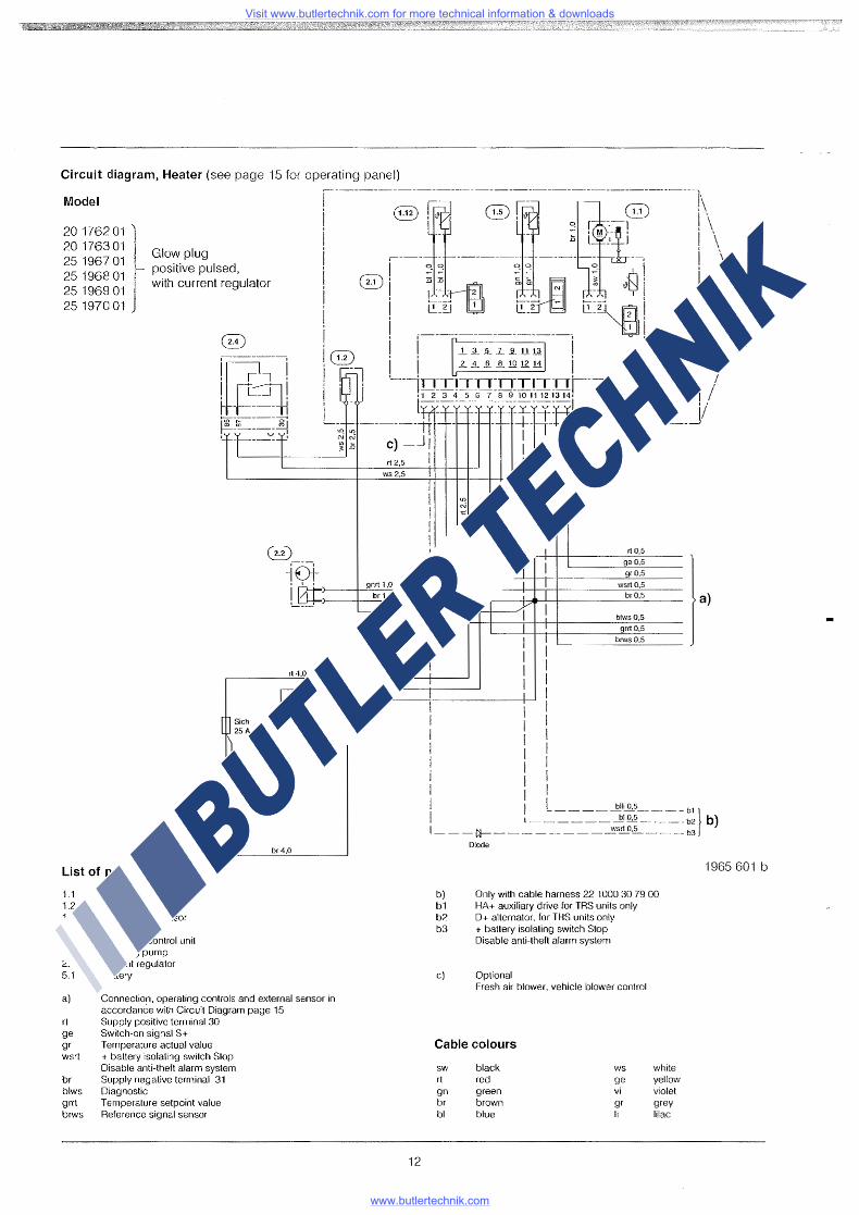
Circuit diagram, Heater (see page 15 for operating panel)
Model
20 1762 01 20 176301 25 1967 01 25 1968 01 25 1969 01 25 1970 01
Glow plug positive pulsed, with current regulator
I]~~~ I rt 1.0
~ii ~1·._T. tJ
List of parts
1. 1 Burner motor 1.2 Glow plug 1.5 Overheating sensor 1. 12 Flame sensor 2.1 Electronic control unit 2.2 Metering pump 2.4 Curren! regulator 5.1 Battery
br4,0
a) Connection, operating controls and external sensor in accordance with Circuit Diagram page 15
rt Supply positive terminal 30 ge Switch-on signal S+ gr Temperature actual value wsrt + battery isolating switch Stop
Disable anti-theft alarm system br Supply negative terminal 31 blws Diagnostic grrt Temperature setpoint value brws Reference signal sensor
12
rt0,5
I ge0,5
gr0,5
I wsrt0,5
I br0,5
I I blws0,5 I grrt0,5
mode
b) b1 b2 b3
Only with cable harness 22 1000 30 79 00 HA+ auxiliary drive for TRS units only D+ alternator, for TRS units only + battery isolating switch Stop Disable anti-theft alarm system
c) Optional Fresh air blower, vehicle blower control
Cable colours
sw black rt red gn green br brown bf blue
ws ge vi gr Ii
white yellow violet grey lilac
a)
1965 601 b
Visit www.butlertechnik.com for more technical information & downloads
www.butlertechnik.com

Circuit diagram~ Heater, standard model {see page 15 for operating panel)
Model
20 1767 01 20 1768 01 25 1980 01 25 1981 01 25 1982 01 25 1983 01
Glow plug positive pulsed
@)
-fDt
ws2,5
• • ' gnrt 1,0
Ll3J:~,___b_r ~1.0-+--~,
List of parts
1.1 1.2 1.5 1.12 2.1 2.2 2.7 2.7.1 5.1
Burner motor Glow plug Overheating sensor Flame sensor Electronic control unit Metering pump Main fuse 12 V = 25 A. 24 V = 15 A Fuses A Battery
a) Connection, operating controls and external sensor in accordance with Circuit Diagram page 14
rt Supply positive terminal 30 ge Switch-on signal S+ gr Temperature actual value wsrt + battery isolating switch Slop
Disable anti-theft alarm system
13
rt 0,5
qe 0,5
qr0,5
wsrt 0,5 br0,5
J blws 0,5
/ qrrt0,5
brws0,5
@)[J @]rn ) rt 1,0
@)~--ii
i~d br4,0
br Supply negative terminal 31 blws Diagnostic grrt Temperature setpoint value brws Reference signal sensor
b) Optional Fresh air blower, vehicle blower control
Cable colours
SW black ws rt red ge gn green vi br brown gr bl blue Ii
a)
1976 601 b
white yellow violet grey lila
Visit www.butlertechnik.com for more technical information & downloads
www.butlertechnik.com
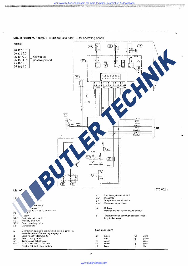
Circuit diagram, Heater, TRS model (see page 15 for operating panel)
Model
20 1767 01 20 176801 25 1980 01 251981 01 25 1982 01 25 1983 01
Glow plug positive pulsed
List of parts
Bumermotor Glow plug Overheating sensor Flame sensor Electronic contro! unit Metering pump Main fuse 12 V = 25 A. 24 V = 15 A Fuse 5A
c)
ws2,5
-roll13;t:~,}--gn~~-~~:~'-t--+---+-----.I
~~7
U}
N' .D
/ /
/
I ------- ----; -~ -----, I I
I Kl.15 I OGD I I ~7 o I
I ~ / >[ i[] I I § o:-"/ @ '
I 6 6 -~+ rt1.0· l
I n n r~~ I
! k ~."=~ @) l'.' !
I ~-~--~--~--~--:::__-~_! br Supply negative terminal 31 blws Diagnostic grrt Temperature setpoint value brws Reference signal sensor
b) Optional
rt0,5
ge0,5
gr0,5
wsrt0.5
br0,5
b!ws0,5
grrt0,5
brws 0,5
Fresh air blower, vehicle blower control
1.1 1.2 1.5 1.12 2.1 2.2 2.7 2.7.1 5.1 5.2.1 5.3 5.3.1 5.5
Battery Battery isolating switch Auxiliary drive HA+ Switch. auxiliary drive Generator D+
c) TRS: for vehicles carrying hazardous loads (e.g. tanker lorry)
a)
rt ge gr wsrl
Connection, operating controls and external sensor in accordance with Circuit Diagram page 14 Supply positive terminal 30 Switch-on signal S+ Temperature actual value + battery isolating switch Stop Disable anti-theft alarm system
14
Cable colours
sw black rt red gn green br brown bl blue
WS
ge vi gr Ii
white yellow violet grey Iii a
a)
1976 602 a
Visit www.butlertechnik.com for more technical information & downloads
www.butlertechnik.com
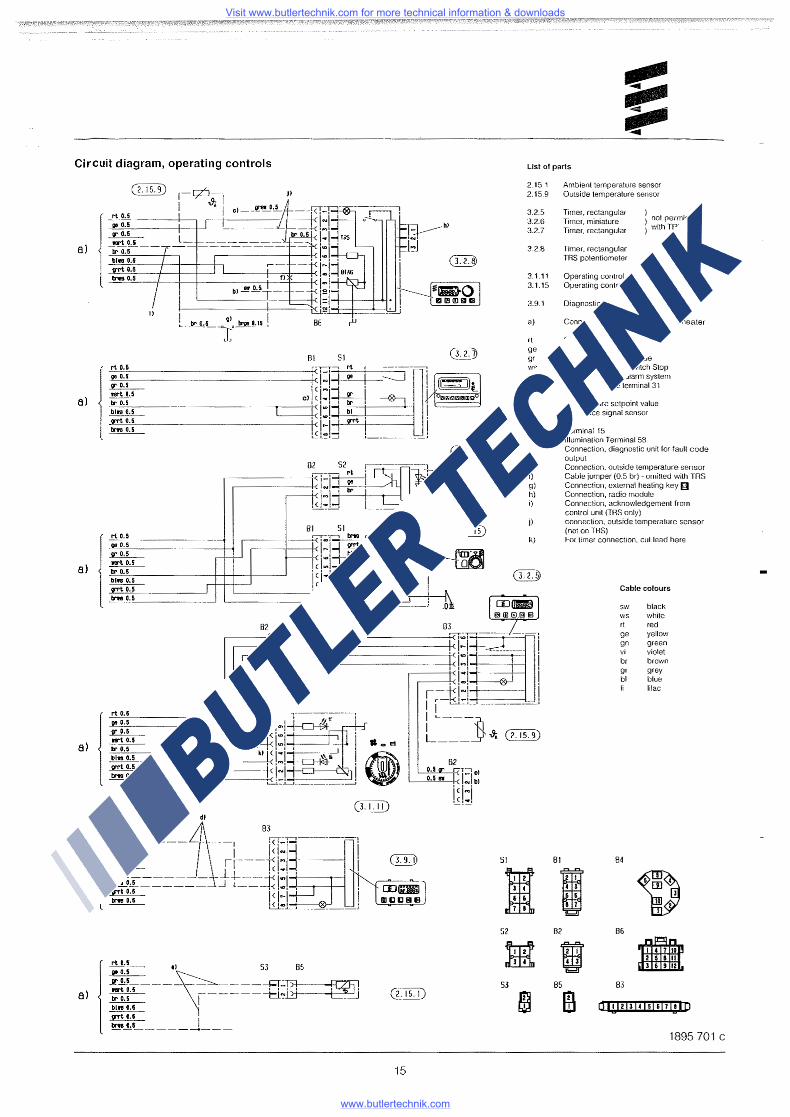
Circuit diagram, operating controls
aJ
8)
a>
a)
JI
l rt 0.5 II& 0.5
~ __!lr_!_~-tr 0.5 b[irs 0.5 f(f't 0.5 trn 0.5
H
86 r"
Bl SI r-,--y---. rt r-------"1
~--------+-<Jcj:j~ • i ~ ~] cli~!=! 1 ~ : JA7c=="'1
--------------+<!~!:! ~I ! ~----------+<1c1.-1 I
t~~l~ ~-------~ l rt 0.5 oe o.5 ~ l!ll't 0.5 tr 0.5
~ ~0.5
Ins 0.5
l rt 0.5 oe o.s ~ ll!l't 0.5 tr 0.5 bin o.s ~0.5
Ina 0.5
l rt 0.5
0.5 1T &.5 ftl't 0.5 Ir 0.5 bha o.5 ~0.5
bMa 0.5
:::: •yl S3 85
!th---- -- -----R~Ii] lr0.5 1------t:L~ bl18 o.s rt o.s I ~_!.5 ________ _
15
List of parts
SI
2.15.1 2.15.9
3.2.5 3.2.6 3.2.7
3.2.8
3.1.11 3.1.15
3.9.1
a)
rl ge gr wsrt
br blws grrt brws
b) c) d)
e) !} g) h) i)
I S2
53
81
82
Ambient temperature sensor Outside temperature sensor
Timer. rectangular Timer, miniature Timer, rectangular
Timer, rectangular TRS po!entiometer
} . . } not perm1ss1ble ) withTRS
Operating control. round Operating control, miniature, less sensor
Diagnostic unit, JE diagnosis
Connection. operating controls to heater
Supply positive terminal 30 Switch-on signal S+ Temperature actual value + battery isolating switch Stop Disable anti-theft alarm system Supply negative terminal 31 Diagnostic Temperature setpoinl value Reference signal sensor
Terminal 15 lllumina!ion Terminal 58 Connection. diagnostic unit for fault code output Connection. outside temperature sensor Cable jumper (0.5 br) - omitted with TRS Connection. external heating key (;11 Connection. radio module Connection. acknowledgement from control unit (TRS only) connection, outside temperature sensor (not 011 TRS) For timer connection, cul lead here
Cable colours
SW black WS white rt red ge yellow gn green vi violet br brown gr grey bl blue
lilac
84
86
I 85 83
IB oi1ulrnisirnleio
1895 701 c
Visit www.butlertechnik.com for more technical information & downloads
www.butlertechnik.com
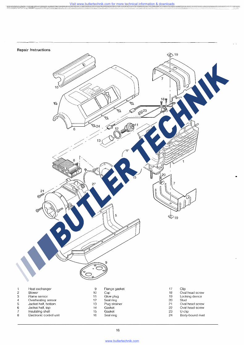
air Instruct· ions Rep·
1 2 3 4 5 6 7 8
BHleat exchanger
ower Flame sensor Overheatin Jacket half g bsensor Jacket half. t ottom In ' op
sulating shell Electronic control unit
9 10 11 12 13 14 15 16
Flange ga k C
set ap
Glow plug Seal ring Plug strainer Gasket Gasket Seal ring
16
17 18 19 20 21 22 23 24
Clip Oval head L . screw s~~~ing device
gval head screw val head sc
U-clip rew
Body-bound rivet
Visit www.butlertechnik.com for more technical information & downloads
www.butlertechnik.com
Repair steps
1 2 3 4
Remove/rnsta!I glow plug Remove/install plug strainer Remove/install electronic control unit Detach cap Detach discharge hood Detach jacket half
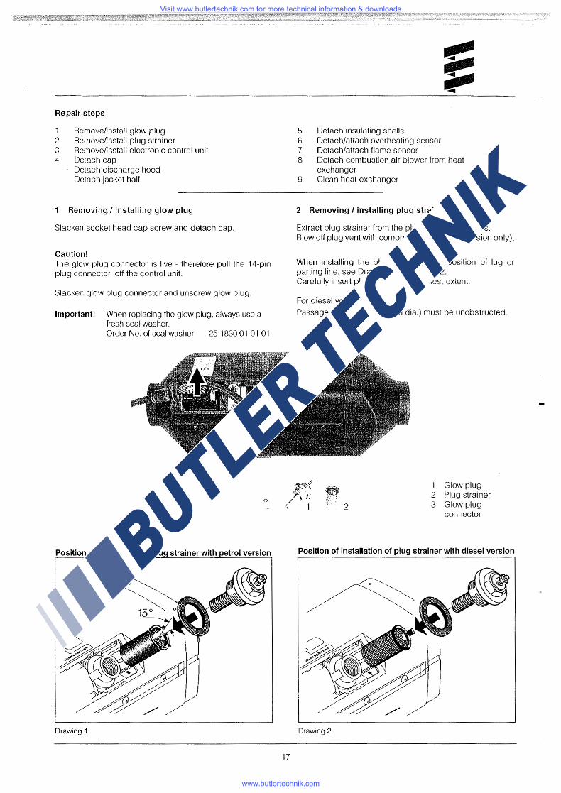
Removing I installing glow plug
Slacken socket head cap screw and detach cap.
Caution! The glow plug connector is live - therefore pull the 14-pin plug connector off the control unit.
Slacken glow plug connector and unscrew glow plug.
Important! When replacing the glow plug, always use a fresh seal washer. Order No. of seal washer 25 1830 01 01 01
3
Figure 1
Position of installation of lu strainer with etrol version
Drawing 1
17
5 6 7 8
9
Detach insulating shells Detach/attach overheating sensor Detach/attach flame sensor Detach combustion air blower from heat exchanger Clean heat exchanger
2 Removing I installing plug strainer
Extract plug strainer from the plug socket with pliers. Blow off plug vent with compressed air (diesel version only).
When installing the plug strainer, note position of lug or parting line, see Drawing 1 or Drawing 2. Carefully insert plug strainer to its fullest extent.
For diesel version:
Passage for plug vent (2 mm dia.) must be unobstructed.
1 Glow plug 2 Plug strainer 3 Glow plug
connector
Position of installation of plug strainer with diesel version
Drawing 2
Visit www.butlertechnik.com for more technical information & downloads
www.butlertechnik.com
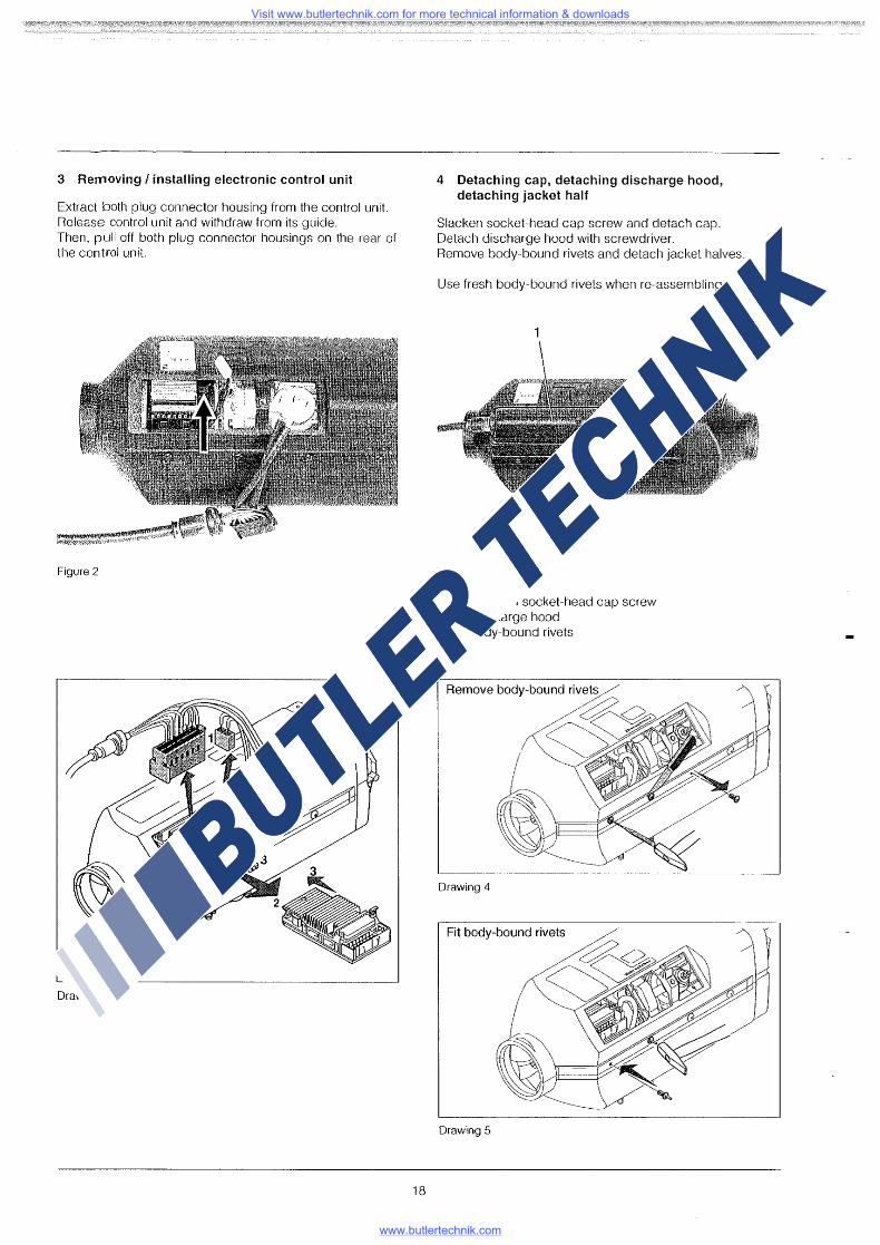
3 Removing I installing electronic control unit
Extract both plug connector housing from the control unit. Release control unit and withdraw from its guide. Then, pull off both plug connector housings on the rear of the control unit
- - -~.~;.~r?~!~~~,~~~~~?.;;=~
Figure 2
Drawing 3
18
4 Detaching cap, detaching discharge hood, detaching jacket half
Slacken socket-head cap screw and detach cap_ Detach discharge hood with screwdriver. Remove body-bound rivets and detach jacket halves_
Use fresh body-bound rivets when re-assembling.
1
3
Figure 3
1 Cap with socket-head cap screw 2 Discharge hood 3 Body-bound rivets
Drawing 4
Drawing 5
2
Visit www.butlertechnik.com for more technical information & downloads
www.butlertechnik.com
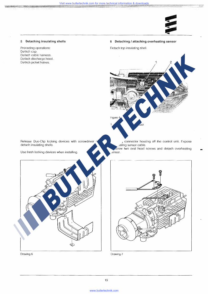
5 Detaching insulating shells
Preceding operations: Detach cap. Detach cable harness. Detach discharge l1ood. Detach jacket halves.
Release Duo-Clip locking devices with screwdriver and detach insulating shells.
Use fresh locking devices when installing.
Drawing 6
19
6 Detaching I attaching overheating sensor
Detach top insulating shell.
2
Figure 4
Overheating sensor 2 Flame sensor
Pull plug connector housing off the control unit. Expose over!1eating sensor cable. Unscrew two oval head screws and detach overheating sensor.
Drawing 7
Visit www.butlertechnik.com for more technical information & downloads
www.butlertechnik.com
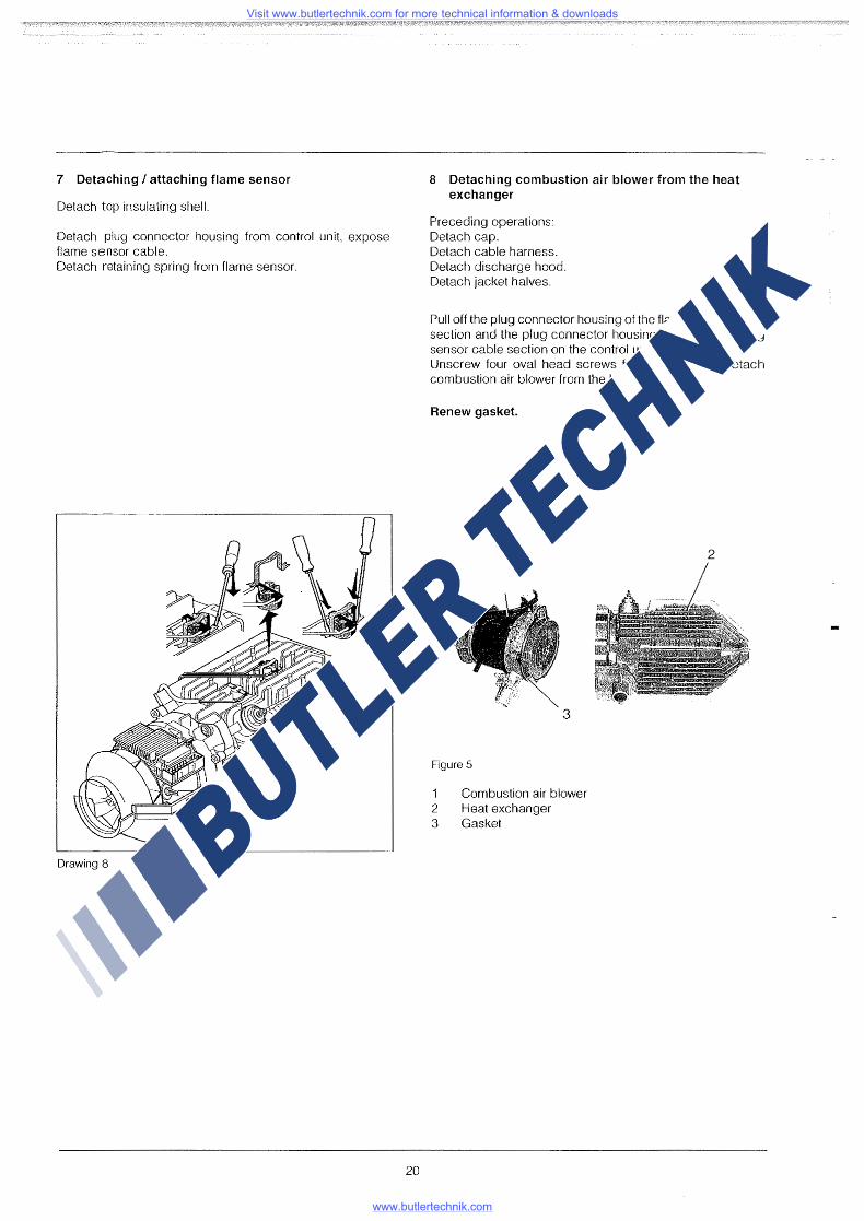
7 Detaching I attaching flame sensor
Detach top insulating shell.
Detach plug connector housing from control unit, expose flame sensor cable. Detach retaining spring from flame sensor.
Drawing 8
20
8 Detaching combustion air blower from the heat exchanger
Preceding operations: Detach cap. Detach cable harness. Detach discharge hood. Detach jacket halves.
Pull off the plug connector housing of the flame sensor cable section and the plug connector housing of the overheating sensor cable section on the control unit. Unscrew four oval head screws from the blower. Detach combustion air blower from the heat exchanger.
Renew gasket.
1 2
3
Figure 5
Combustion air blower 2 Heat exchanger 3 Gasket
Visit www.butlertechnik.com for more technical information & downloads
www.butlertechnik.com
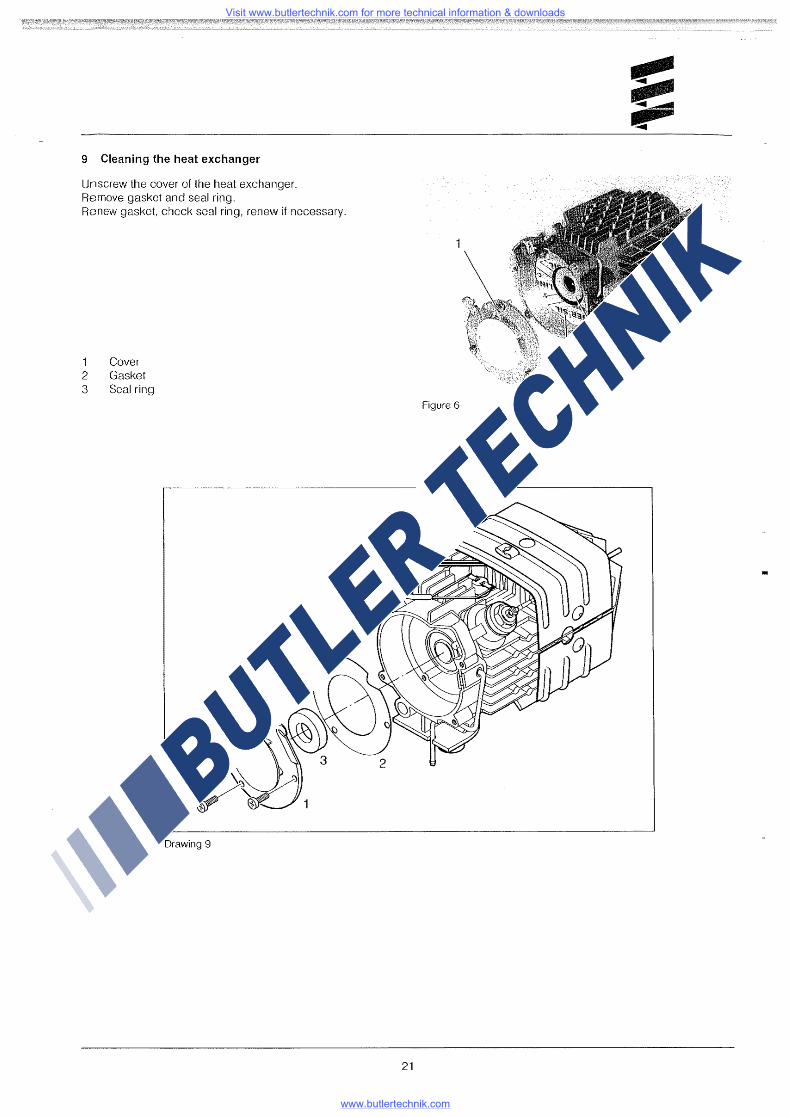
9 Cleaning the heat exchanger
Unscrew the cover of the heat exchanger_ Remove gasket and seal ring_ Renew gasket, check seal ring, renew if necessary_
1 Cover 2 Gasket 3 Seal ring
Drawing 9
Figure 6
21
Visit www.butlertechnik.com for more technical information & downloads
www.butlertechnik.com
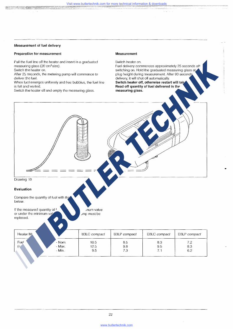
Measurement of fuel delivery
Preparation for measurement
Pull the fuel line off the heater and insert in a graduated measuring glass (20 cm3 size). Switch the heater on. After 25 seconds, the metering pump will commence to deliver the fuel. When fuel emerges uniformly and free bubbles, the fuel line is full and vented. Switch tile heater off and empty the measuring glass.
Drawing 10
Evaluation
Compare the quantity of fuel with the values in the table below.
If the measured quantity of fuel is over the maximum value or under the minimum value, the metering pump must be replaced.
Heater Model B3LC compact
Fuel quantity -Norn. 10.5 (cm3 / 90 s) - Max. 12.5
- Min. 9.5
22
Measurement
Switch heater on. Fuel delivery commences approximately 25 seconds after switching on. Hold the graduated measuring glass at glow plug height during measurement. After 90 seconds of fuel delivery, it will shut off automatically. Switch heater off, otherwise restart will take place. Read off quantity of fuel delivered in the graduated measuring glass.
B3LP compact D3LC compact D3LP compact
8.5 8.3 7.2 9.8 9.5 8.3 7.3 7.1 6.2
Visit www.butlertechnik.com for more technical information & downloads
www.butlertechnik.com