Embed Size (px)
Citation preview
Fans| Air handling units | Air Distribution Products | Fire Safety | Air Curtains and Heating Products| Tunnel Fans
Fire Safetyin Ventilation Systems
DS 428.4Foreword The standard contains a number of requirements that dictate how to achieve a responsible fire technical safety and operation of ventilation sys-tems.
IntroductionThe standard contains a number of requirements to ensure a responsible fire technical construc-tion of ventilation systems, so that the risk for start, developing and spreading of a fire due to the ventilation system is minimized.
ScopeThe purpose of this standard is to ensure that mechanical ventilation systems shall be designed, executed and maintained in such a manner that the potential for start, developing and spreading of a fire due to the system is minimized. The standard contains requirements regarding design, construction, testing, and operation of mechanical ventilation systems.
The standard applies to mechanical and hybrid ventilation systems permanently installed in buildings. Installations for natural ventilation must be performed according to this standard to the extent that they can be assimilated with mechanical ventilation.
Installations for industrial or semi-industrial pro-cesses and storage should at least follow the requirements in the standard, but there may be additional requirements from authorities.
DefinitionsFire section: Separation with building material class (R) EI60 A2-s1, d0 (formerly BS60)Fire cell: Separation with building material class (R) EI60 (formerly BD60) R: Carrying capacityE: IntegrityI: IsolationS: Tightness for smoke
Systemair has a complete range of components for fire protection of ventilation systems. This brochure will provide a list of the most commonly used components, including fire- and smoke dampers, smoke dampers, smoke evacuation dampers and a fire control system for monitoring and exercising of the dampers. It also shows various system solutions that provide an overview of the different possible combinations, all of which are in accordance with the fire protection standard DS 428.4.
DS 428.4
A2: Non-combustible materialS1: Very limited smoke developmentD0: No burning dropletsRV: Smoke fan intended for a smoke extraction systemHo: HorizontalVe: Verticalio: Fire from the inside and outside.
Fire-, flame-, smoke- and smoke evacuation dampersBRS: Fire- and smoke damper class EI60 (ve ho io)S, 70 °C fire thermostat, spring-return actu-ator. Shall prevent fire and smoke being spread between fire sections.
FRS: Flame- and smoke damper class E60 (ve ho io)S, 70 °C fire thermostat, spring-return actuator. Shall prevent smoke being spread between fire sections.
RS: Smoke damper class E30 (ve ho io)S, spring-return actuator. Shall prevent smoke being spread between fire cells.
RES: Smoke evacuation damper class E30 (ve ho io)S, spring-return actuator. Must ensure the discharge of smoke during a fire situation.
Dampers shall be tested according to EN 1366 and classified according to EN 13501-3, appen-dix classes ho ve io. Monitoring must be installed through the control system, which checks the function of the sensors and damper actuators.
Flexible connections: Must comply with class A2-s1,d0, melting point of at least 850 °C, max length of 300 mm for fan connections in unexploitable attic.
Roof curbs: Must be insulated with 50 mm insu-lation A2-s1,d0, through the roof, minimum 100 mm under and 100 mm above the roof.
System solutions:The duct system must be such designed, that the risk of smoke and fire spreading to other fire cells, fire sections or similar building units is not increased.
Damper-secured system:Securing a ventilation system against spreading of smoke must be based on the creation of rea-sonable security against that smoke and combustion products can enter the duct system.
Smoke-ventilated systems:Securing a ventilation system against spreading of smoke must be based on the creation of rea-sonable security against that smoke and com-bustion products, which have entered the duct system, can not be spread through the duct sys-tem to other fire cells, fire sections or similar building units.
A smoke-ventilated system must be such designed, that smoke in the system is dis-charged to the outside with reasonable safety. A smoke-ventilated system cannot be combined with fire-, flame- and/or smoke damper, which prevents the discharge of smoke that has entered the system. With the exception of the outermost fire cell or similar building units, from where spreading of smoke to other fire cells, or similar building units are impossible. In a smoke-ventilated system, the smoke must run via a duct, by-passing parts of the system with large flow resistance, or components in which the risk of clogging of the smoke particles from a fire is great. This includes filters, heat recovery compo-nents, heating- and cooling coils, etc.
Code for technical measures forfire protection in ventilation systems
| Fire safety2
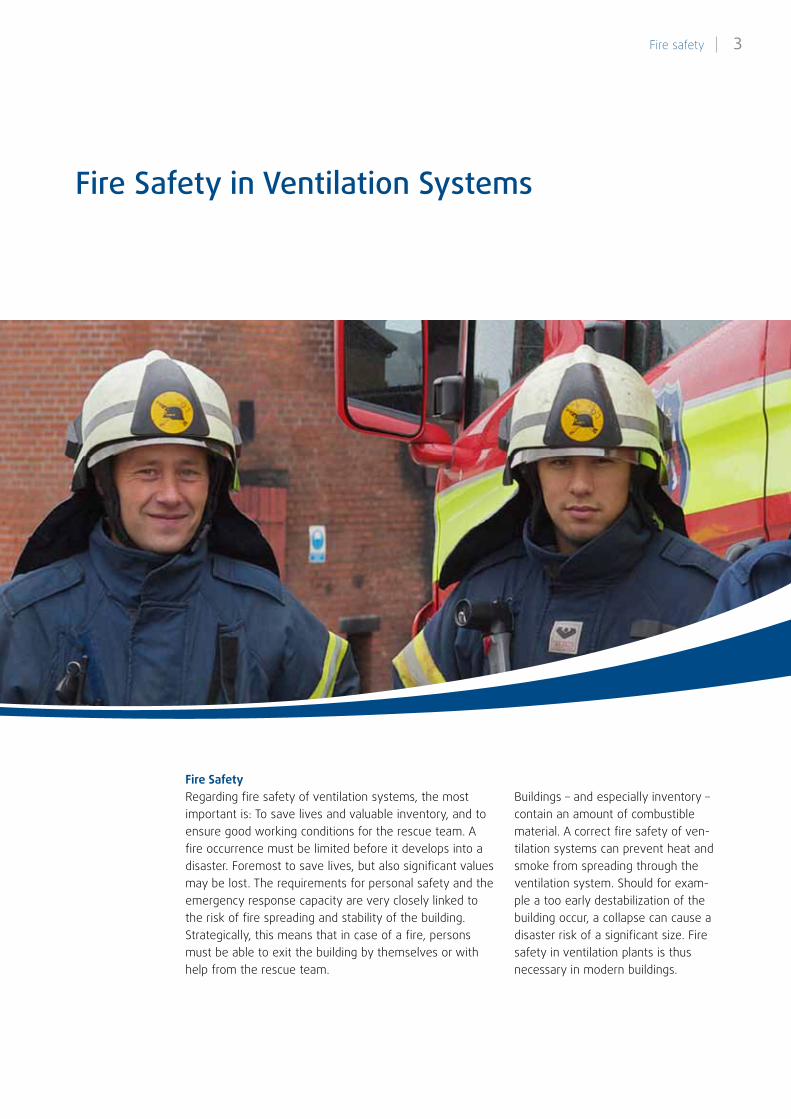
Fire SafetyRegarding fire safety of ventilation systems, the most important is: To save lives and valuable inventory, and to ensure good working conditions for the rescue team. A fire occurrence must be limited before it develops into a disaster. Foremost to save lives, but also significant values may be lost. The requirements for personal safety and the emergency response capacity are very closely linked to the risk of fire spreading and stability of the building. Strategically, this means that in case of a fire, persons must be able to exit the building by themselves or with help from the rescue team.
Fire Safety in Ventilation Systems
Buildings – and especially inventory – contain an amount of combustible material. A correct fire safety of ven-tilation systems can prevent heat and smoke from spreading through the ventilation system. Should for exam-ple a too early destabilization of the building occur, a collapse can cause a disaster risk of a significant size. Fire safety in ventilation plants is thus necessary in modern buildings.
3 Fire safety |
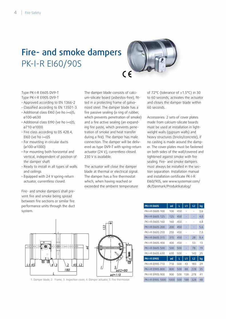
PK-I-R EI60/90SFire- and smoke dampers
Type PK-I-R EI60S DV9-T Type PK-I-R EI90S DV9-T• Approved according to EN 1366-2• Classified according to EN 13501-3• Additional class EI60 (ve ho io)S,
ø100-ø630• Additional class EI90 (ve ho io)S,
ø710-ø1000• Fire class according to DS 428.4,
EI60 (ve ho io)S• For mounting in circular ducts
(ø100-ø1000)• For mounting both horizontal and
vertical, independent of position of the damper shaft
• Ready to install in all types of walls and ceilings
• Equipped with 24 V spring-return actuator, currentless closed.
Fire- and smoke dampers shall pre-vent fire and smoke being spread between fire sections or similar fire performance units through the duct system.
1. Damper blade, 2. Frame, 3. Inspection cover, 4. Damper actuator, 5. Fire thermostat
ød/2+80ød+110
1
122
L2L1
L
45 45
ød
4 23180
5
The damper blade consists of calci-um-silicate board (asbestos-free), fit-ted in a protecting frame of galva-nized steel. The damper blade has a fire passive sealing (a ring of rubber, which prevents penetration of smoke) and a fire active sealing (an expand-ing fire paste, which prevents pene-tration of smoke and heat transfer during a fire). The damper has male connection. The damper will be deliv-ered as type DV9-T with spring-return actuator (24 V), currentless closed. 230 V is available.
The actuator will close the damper blade at thermal or electrical signal. The damper has a fire thermostat which, when having reached or exceeded the ambient temperature
of 72°C (tolerance of ±1.5°C) in 30 to 60 seconds, activates the actuator and closes the damper blade within 60 seconds.
Accessories: 2 sets of cover plates made from calcium-silicate boards must be used at installation in light-weight walls (gypsum walls) and heavy structures (bricks/concrete), if no casting is made around the damp-er. The cover plates must be fastened on both sides of the wall/covered and tightened against smoke with fire sealing. Fire- and smoke dampers must always be installed in the sec-tion separation. Installation manual and installation certificate PK-I-R EI60/90S, see www.systemair.com/dk/Danmark/Produktkatalog/
PK-I-R EI60S ød L L1 L2 kg
PK-I-R EI60S 100 100 450 - - 3,6
PK-I-R EI60S 125 125 450 - - 4,0
PK-I-R EI60S 160 160 450 - - 4,8
PK-I-R EI60S 200 200 450 - - 5,6
PK-I-R EI60S 250 250 450 - - 7,0
PK-I-R EI60S 315 315 450 - 28 9,4
PK-I-R EI60S 400 400 450 - 53 13
PK-I-R EI60S 500 500 500 - 78 19
PK-I-R EI60S 630 630 500 - 143 25
PK-I-R EI90S ød L L1 L2 kg
PK-I-R EI90S 710 710 500 43 183 29
PK-I-R EI90S 800 800 500 88 228 35
PK-I-R EI90S 900 900 500 138 278 41
PK-I-R EI90S 1000 1000 500 188 328 48
| Fire Safety4
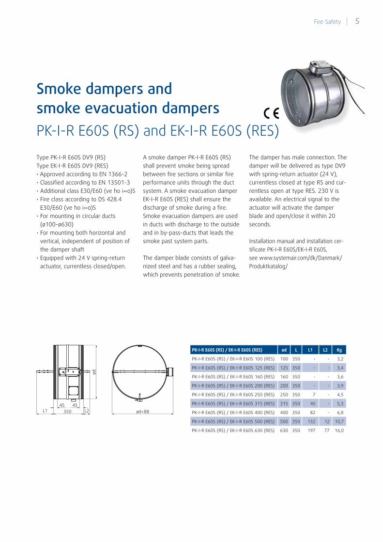
PK-I-R E60S (RS) and EK-I-R E60S (RES)
Smoke dampers andsmoke evacuation dampers
Type PK-I-R E60S DV9 (RS) Type EK-I-R E60S DV9 (RES)• Approved according to EN 1366-2• Classified according to EN 13501-3• Additional class E30/E60 (ve ho io)S• Fire class according to DS 428.4
E30/E60 (ve ho io)S • For mounting in circular ducts
(ø100-ø630)• For mounting both horizontal and
vertical, independent of position of the damper shaft
• Equipped with 24 V spring-return actuator, currentless closed/open.
A smoke damper PK-I-R E60S (RS) shall prevent smoke being spread between fire sections or similar fire performance units through the duct system. A smoke evacuation damper EK-I-R E60S (RES) shall ensure the discharge of smoke during a fire. Smoke evacuation dampers are used in ducts with discharge to the outside and in by-pass-ducts that leads the smoke past system parts.
The damper blade consists of galva-nized steel and has a rubber sealing, which prevents penetration of smoke.
The damper has male connection. The damper will be delivered as type DV9 with spring-return actuator (24 V), currentless closed at type RS and cur-rentless open at type RES. 230 V is available. An electrical signal to the actuator will activate the damper blade and open/close it within 20 seconds.
Installation manual and installation cer-tificate PK-I-R E60S/EK-I-R E60S,see www.systemair.com/dk/Danmark/Produktkatalog/
PK-I-R E60S (RS) / EK-I-R E60S (RES) ød L L1 L2 Kg
PK-I-R E60S (RS) / EK-I-R E60S 100 (RES) 100 350 - - 3,2
PK-I-R E60S (RS) / EK-I-R E60S 125 (RES) 125 350 - - 3,4
PK-I-R E60S (RS) / EK-I-R E60S 160 (RES) 160 350 - - 3,6
PK-I-R E60S (RS) / EK-I-R E60S 200 (RES) 200 350 - - 3,9
PK-I-R E60S (RS) / EK-I-R E60S 250 (RES) 250 350 7 - 4,5
PK-I-R E60S (RS) / EK-I-R E60S 315 (RES) 315 350 40 - 5,3
PK-I-R E60S (RS) / EK-I-R E60S 400 (RES) 400 350 82 - 6,8
PK-I-R E60S (RS) / EK-I-R E60S 500 (RES) 500 350 132 12 10,7
PK-I-R E60S (RS) / EK-I-R E60S 630 (RES) 630 350 197 77 16,0
350
ød
45 45L1 ød+88L2
5 Fire Safety |
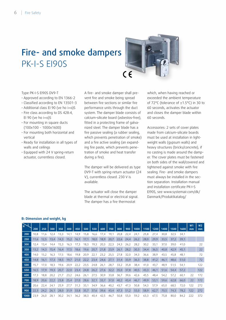
200 250 300 350 400 450 500 550 600 700 800 900 1000 1100 1200 1400 1500 1600 W1 mm
W2 mm
200 10,8 11,6 12,4 13,3 14,1 14,9 15,8 16,6 17,4 19,1 20,8 22,4 24,1 25,8 27,4 30,8 32,5 34,1
250 11,6 12,5 13,4 14,3 15,2 16,1 17,1 18,0 18,9 20,7 22,6 24,4 26,2 28,0 29,9 33,5 37,2 39,1
300 12,4 13,4 14,4 15,3 16,3 17,3 18,3 19,3 20,3 22,3 24,3 26,2 28,2 30,2 33,1 37,0 39,0 41,0 22
350 13,2 14,3 15,4 16,4 17,5 18,6 19,6 20,7 21,8 23,9 26,1 28,2 30,3 34,4 36,5 40,8 42,9 45,1 22
400 14,0 15,2 16,3 17,5 18,6 19,8 20,9 22,1 23,2 25,5 27,8 32,0 34,3 36,6 38,9 43,5 45,8 48,1 72
450 14,8 16,1 17,3 18,5 19,7 21,0 22,2 23,4 24,6 27,1 31,4 33,9 36,3 38,8 41,2 46,1 48,6 51,0 72
500 15,7 17,0 18,3 19,6 20,9 22,2 23,5 24,8 26,1 28,7 33,2 35,8 38,4 41,0 43,7 48,9 51,5 54,1 122
550 16,5 17,9 19,3 20,7 22,0 23,4 24,8 26,2 27,6 32,2 35,0 37,8 40,5 43,3 46,1 51,6 54,4 57,2 122
600 17,3 18,8 20,2 21,7 23,2 24,6 26,1 27,5 30,9 33,8 36,7 39,6 42,6 45,5 48,4 54,2 57,2 60,1 22 172
700 18,9 20,6 22,2 23,8 25,4 27,0 28,6 32,1 33,7 37,0 40,2 43,4 46,7 49,9 53,1 59,6 62,8 66,0 22 172
800 20,6 22,4 24,1 25,9 27,7 31,3 33,1 34,9 36,6 40,2 43,7 47,3 50,8 54,3 57,9 65,0 68,5 72,0 122 272
900 22,3 24,2 26,1 28,0 31,9 33,8 35,7 37,6 39,6 43,4 47,3 51,2 55,0 58,9 62,7 70,5 74,3 78,2 122 272
1000 23,9 26,0 28,1 30,2 34,1 36,2 38,3 40,4 42,5 46,7 50,8 55,0 59,2 63,3 67,5 75,8 80,0 84,2 222 372
PK-I-S EI90SFire- and smoke dampers
B: Dimension and weight, kg
Type PK-I-S EI90S DV9-T• Approved according to EN 1366-2• Classified according to EN 13501-3• Additional class EI 90 (ve ho io)S• Fire class according to DS 428:4,
EI 90 (ve ho io)S• For mounting in square ducts
(100x100 - 1000x1600)• For mounting both horizontal and
vertical• Ready for installation in all types of
walls and ceilings• Equipped with 24 V spring-return
actuator, currentless closed.
A fire- and smoke damper shall pre-vent fire and smoke being spread between fire sections or similar fire performance units through the duct system. The damper blade consists of calcium-silicate board (asbestos-free), fitted in a protecting frame of galva-nized steel. The damper blade has a fire passive sealing (a rubber sealing, which prevents penetration of smoke) and a fire active sealing (an expand-ing fire paste, which prevents pene-tration of smoke and heat transfer during a fire).
The damper will be delivered as type DV9-T with spring-return actuator (24 V), currentless closed. 230 V is available.
The actuator will close the damper blade at thermal or electrical signal. The damper has a fire thermostat
which, when having reached or exceeded the ambient temperature of 72°C (tolerance of ±1.5°C) in 30 to 60 seconds, activates the actuator and closes the damper blade within 60 seconds.
Accessories: 2 sets of cover plates made from calcium-silicate boards must be used at installation in light-weight walls (gypsum walls) and heavy structures (bricks/concrete), if no casting is made around the damp-er. The cover plates must be fastened on both sides of the wall/covered and tightened against smoke with fire sealing. Fire- and smoke dampers must always be installed in the sec-tion separation. Installation manual and installation certificate PK-I-S EI90S, see www.systemair.com/dk/Danmark/Produktkatalog/
H L
| Fire Safety6
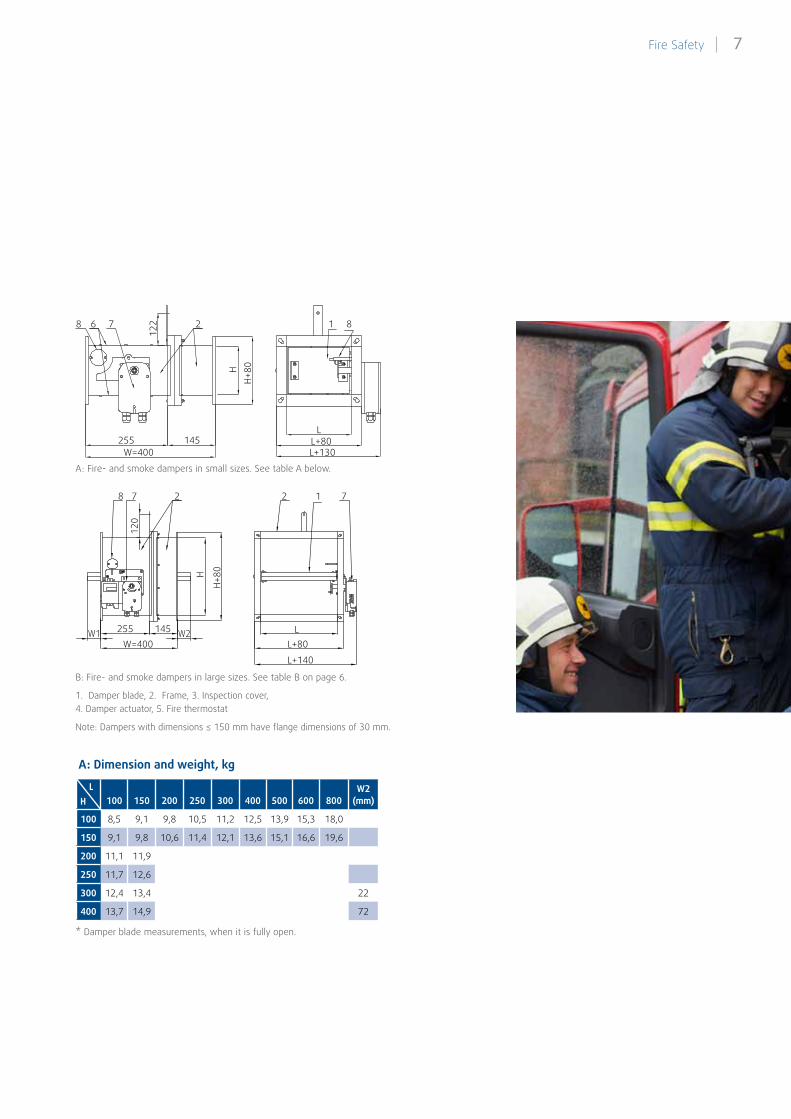
* Damper blade measurements, when it is fully open.
A: Fire- and smoke dampers in small sizes. See table A below.
B: Fire- and smoke dampers in large sizes. See table B on page 6.
100 150 200 250 300 400 500 600 800W2
(mm)
100 8,5 9,1 9,8 10,5 11,2 12,5 13,9 15,3 18,0
150 9,1 9,8 10,6 11,4 12,1 13,6 15,1 16,6 19,6
200 11,1 11,9
250 11,7 12,6
300 12,4 13,4 22
400 13,7 14,9 72
1. Damper blade, 2. Frame, 3. Inspection cover, 4. Damper actuator, 5. Fire thermostat
Note: Dampers with dimensions ≤ 150 mm have flange dimensions of 30 mm.
A: Dimension and weight, kg
7
1226 2
255 145W=400 L+130
L+80L
1 8
HH+
80
8
8
255 145
L+140
L+80L
W=400W1 W2
7 2
120
H
H+80
2 1 7
HL
7 Fire Safety |
Fire Safety in Ventilation Systems
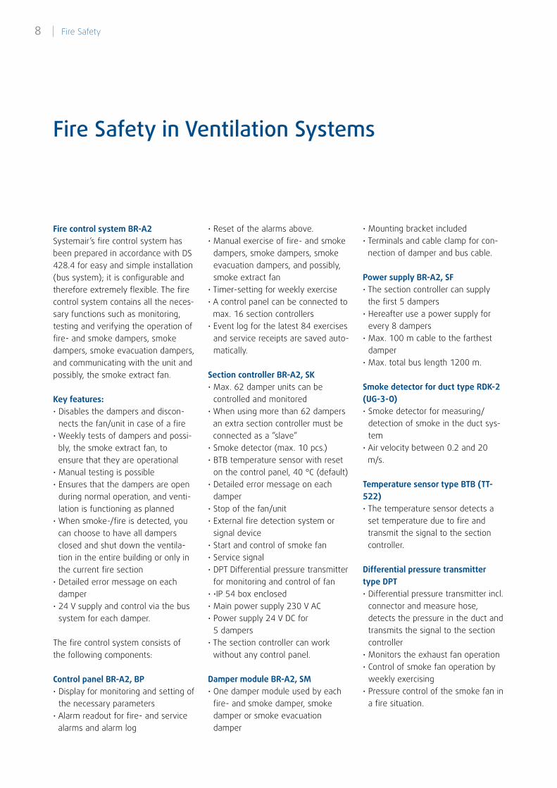
Fire control system BR-A2Systemair’s fire control system has been prepared in accordance with DS 428.4 for easy and simple installation (bus system); it is configurable and therefore extremely flexible. The fire control system contains all the neces-sary functions such as monitoring, testing and verifying the operation of fire- and smoke dampers, smoke dampers, smoke evacuation dampers, and communicating with the unit and possibly, the smoke extract fan.
Key features:• Disables the dampers and discon-
nects the fan/unit in case of a fire• Weekly tests of dampers and possi-
bly, the smoke extract fan, to ensure that they are operational
• Manual testing is possible • Ensures that the dampers are open
during normal operation, and venti-lation is functioning as planned
• When smoke-/fire is detected, you can choose to have all dampers closed and shut down the ventila-tion in the entire building or only in the current fire section
• Detailed error message on each damper
• 24 V supply and control via the bus system for each damper.
The fire control system consists of the following components:
Control panel BR-A2, BP• Display for monitoring and setting of
the necessary parameters • Alarm readout for fire- and service
alarms and alarm log
• Reset of the alarms above.• Manual exercise of fire- and smoke
dampers, smoke dampers, smoke evacuation dampers, and possibly, smoke extract fan
• Timer-setting for weekly exercise• A control panel can be connected to
max. 16 section controllers• Event log for the latest 84 exercises
and service receipts are saved auto-matically.
Section controller BR-A2, SK• Max. 62 damper units can be
controlled and monitored • When using more than 62 dampers
an extra section controller must be connected as a ”slave”
• Smoke detector (max. 10 pcs.)• BTB temperature sensor with reset
on the control panel, 40 °C (default)• Detailed error message on each
damper• Stop of the fan/unit• External fire detection system or
signal device• Start and control of smoke fan• Service signal• DPT Differential pressure transmitter
for monitoring and control of fan• •IP 54 box enclosed• Main power supply 230 V AC• Power supply 24 V DC for
5 dampers• The section controller can work
without any control panel.
Damper module BR-A2, SM• One damper module used by each
fire- and smoke damper, smoke damper or smoke evacuation damper
• Mounting bracket included• Terminals and cable clamp for con-
nection of damper and bus cable.
Power supply BR-A2, SF• The section controller can supply
the first 5 dampers • Hereafter use a power supply for
every 8 dampers• Max. 100 m cable to the farthest
damper• Max. total bus length 1200 m.
Smoke detector for duct type RDK-2 (UG-3-O)• Smoke detector for measuring/
detection of smoke in the duct sys-tem
• Air velocity between 0.2 and 20 m/s.
Temperature sensor type BTB (TT-522)• The temperature sensor detects a
set temperature due to fire and transmit the signal to the section controller.
Differential pressure transmitter type DPT• Differential pressure transmitter incl.
connector and measure hose, detects the pressure in the duct and transmits the signal to the section controller
• Monitors the exhaust fan operation• Control of smoke fan operation by
weekly exercising• Pressure control of the smoke fan in
a fire situation.
| Fire Safety8
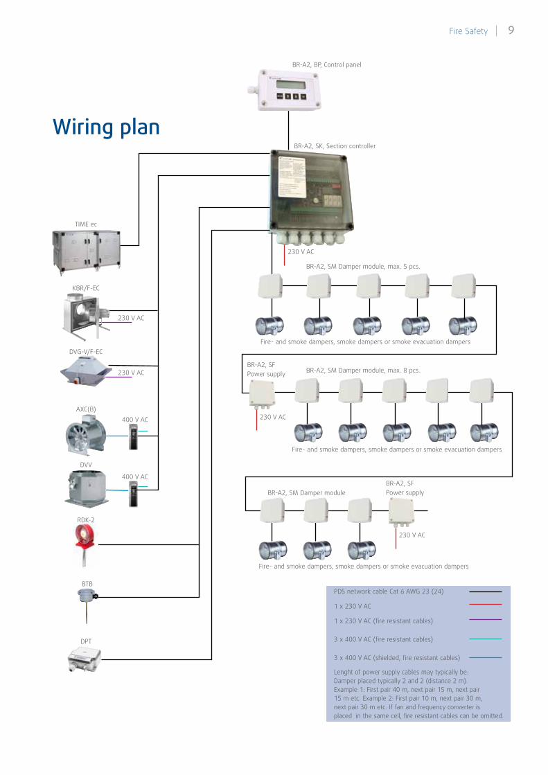
Wiring plan
TIME ec
BR-A2, SK, Section controller
BR-A2, SFPower supply
BR-A2, SF Power supply
Fire- and smoke dampers, smoke dampers or smoke evacuation dampers
Fire- and smoke dampers, smoke dampers or smoke evacuation dampers
Fire- and smoke dampers, smoke dampers or smoke evacuation dampers
KBR/F-EC
DVG-V/F-EC
AXC(B)
DVV
RDK-2
DPT
BTB
400 V AC
230 V AC
230 V AC
230 V AC
400 V AC
BR-A2, SM Damper module, max. 5 pcs.
BR-A2, SM Damper module, max. 8 pcs.
BR-A2, SM Damper module
230 V AC
230 V AC
PDS network cable Cat 6 AWG 23 (24)
1 x 230 V AC
1 x 230 V AC (fire resistant cables)
3 x 400 V AC (fire resistant cables)
3 x 400 V AC (shielded, fire resistant cables)
Lenght of power supply cables may typically be:Damper placed typically 2 and 2 (distance 2 m). Example 1: First pair 40 m, next pair 15 m, next pair 15 m etc. Example 2: First pair 10 m, next pair 30 m, next pair 30 m etc. If fan and frequency converter is placed in the same cell, fire resistant cables can be omitted.
BR-A2, BP, Control panel
9 Fire Safety |
Excerpts from DS 428.4Damper-secured system
Damper-secured systems can be used in all usage categories, but are most suitable for usage category 1, 2, 3, and 6. These usage categories are all buildings for day time occupancy, where ventilation often will be stopped at night. These categories include for instance:
1: Offices, industrial and warehouse buildings, certain garages, outbuild-ings and carports.
2: Teaching rooms, school day-care centers, after-school facilities, day centers.
3: Shops, shopping malls, places of public assembly, meeting rooms, canteens, restaurants, cinemas,
discotheques, theatres.
RS
RS
RS
RDK-2
Ventilation roomFire cell
Unexplorableattic
AKHI
ULHI DPT
RS
PR
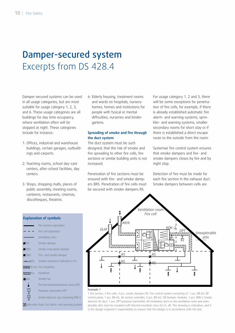
Example 11 fire section, 3 fire cells: 4 pcs. smoke dampers RS. Fire control system consisting of: 1 pcs. BR-A2, BP control panel, 1 pcs. BR-A2, SK section controller, 4 pcs. BR-A2, SM Damper modules, 1 pcs. RDK-2 Smoke detector for duct, 1 pcs. DPT pressure transmitter. All ventilation ducts in the ventilation room and unex-plorable attic must be insulated with thermal insulation class A2-s1, d0. The drawing is indicative, and it is the design engineer’s responsibility to ensure that the design is in accordance with the law.
6: Elderly housing, treatment rooms and wards on hospitals, nursery-homes, homes and institutions for people with fysical or mental difficulties, nurseries and kinder- gartens.
Spreading of smoke and fire through the duct systemThe duct system must be such designed, that the risk of smoke and fire spreading to other fire cells, fire sections or similar building units is not increased.
Penetration of fire sections must be ensured with fire- and smoke damp-ers BRS. Penetration of fire cells must be secured with smoke dampers RS.
For usage category 1, 2 and 3, there will be some exceptions for penetra-tion of fire cells, for example, if there is already established automatic fire alarm- and warning systems, sprin-kler- and warning systems, smaller secondary rooms for short stay or if there is established a direct escape route to the outside from the room.
Systemair fire control system ensures that smoke dampers and fire- and smoke dampers closes by fire and by night stop.
Detection of fire must be made for each fire section in the exhaust duct. Smoke dampers between cells are
Explanation of symbols
Fire section separation
Fire cell separation
Ventilation duct
Smoke damper
Smoke evacuation damper
Fire- and smoke damper
Smoke resistance indicated in Pa
Fire insulation
Insulation
Smoke fan
Fire thermostat/temperature sensor BTB
Pressure transmitter DPT
Smoke detector, duct mounting RDK-2
Auto. fire alarm- and warning system
RS
RES
BRS
Pa
B-iso
Iso
RV
ABA+AVA
P
R
x xx
| Fire Safety10
activated by the shared detector of the current fire section.
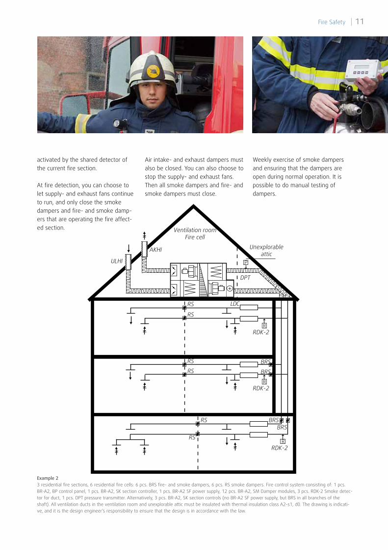
At fire detection, you can choose to let supply- and exhaust fans continue to run, and only close the smoke dampers and fire- and smoke damp-ers that are operating the fire affect-ed section.
Example 23 residential fire sections, 6 residential fire cells: 6 pcs. BRS fire- and smoke dampers, 6 pcs. RS smoke dampers. Fire control system consisting of: 1 pcs. BR-A2, BP control panel, 1 pcs. BR-A2, SK section controller, 1 pcs. BR-A2 SF power supply, 12 pcs. BR-A2, SM Damper modules, 3 pcs. RDK-2 Smoke detec-tor for duct, 1 pcs. DPT pressure transmitter. Alternatively, 3 pcs. BR-A2, SK section controls (no BR-A2 SF power supply, but BRS in all branches of the shaft). All ventilation ducts in the ventilation room and unexplorable attic must be insulated with thermal insulation class A2-s1, d0. The drawing is indicati-ve, and it is the design engineer’s responsibility to ensure that the design is in accordance with the law.
BRS
BRS
BRSBRS
RS
RS
RS
RS
RS
RS
Ventilation roomFire cell
Unexplorableattic
RDK-2
AKHI
ULHI
DPT
LDC
P
R
RDK-2R
RDK-2R
Air intake- and exhaust dampers must also be closed. You can also choose to stop the supply- and exhaust fans. Then all smoke dampers and fire- and smoke dampers must close.
Weekly exercise of smoke dampers and ensuring that the dampers are open during normal operation. It is possible to do manual testing of dampers.
11 Fire Safety |
Excerpts from DS 428.4Smoke-ventilated system
RS
RS
RES
RES
RES
RV
30 Pa 30 Pa 30 Pa30 Pa
50 Pa 50 Pa 50 Pa 50 Pa 50 Pa
30 PaP
Ventilation roomFire cell
AKHIULHI
DPTPBTB
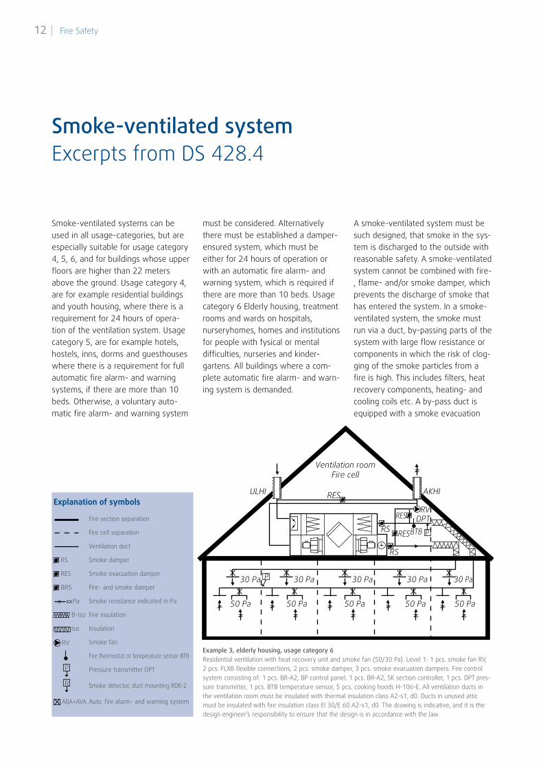
Example 3, elderly housing, usage category 6Residential ventilation with heat recovery unit and smoke fan (50/30 Pa). Level 1: 1 pcs. smoke fan RV, 2 pcs. FLXB flexible connections, 2 pcs. smoke damper, 3 pcs. smoke evacuation dampers. Fire control system consisting of: 1 pcs. BR-A2, BP control panel, 1 pcs. BR-A2, SK section controller, 1 pcs. DPT pres-sure transmitter, 1 pcs. BTB temperature sensor, 5 pcs. cooking hoods H-106-E. All ventilation ducts in the ventilation room must be insulated with thermal insulation class A2-s1, d0. Ducts in unused attic must be insulated with fire insulation class EI 30/E 60 A2-s1, d0. The drawing is indicative, and it is the design engineer’s responsibility to ensure that the design is in accordance with the law.
Smoke-ventilated systems can be used in all usage-categories, but are especially suitable for usage category 4, 5, 6, and for buildings whose upper floors are higher than 22 meters above the ground. Usage category 4, are for example residential buildings and youth housing, where there is a requirement for 24 hours of opera-tion of the ventilation system. Usage category 5, are for example hotels, hostels, inns, dorms and guesthouses where there is a requirement for full automatic fire alarm- and warning systems, if there are more than 10 beds. Otherwise, a voluntary auto-matic fire alarm- and warning system
must be considered. Alternatively there must be established a damper-ensured system, which must be either for 24 hours of operation or with an automatic fire alarm- and warning system, which is required if there are more than 10 beds. Usage category 6 Elderly housing, treatment rooms and wards on hospitals, nurseryhomes, homes and institutions for people with fysical or mental difficulties, nurseries and kinder- gartens. All buildings where a com-plete automatic fire alarm- and warn-ing system is demanded.
A smoke-ventilated system must be such designed, that smoke in the sys-tem is discharged to the outside with reasonable safety. A smoke-ventilated system cannot be combined with fire-, flame- and/or smoke damper, which prevents the discharge of smoke that has entered the system. In a smoke-ventilated system, the smoke must run via a duct, by-passing parts of the system with large flow resistance or components in which the risk of clog-ging of the smoke particles from a fire is high. This includes filters, heat recovery components, heating- and cooling coils etc. A by-pass duct is equipped with a smoke evacuation
Explanation of symbols
Fire section separation
Fire cell separation
Ventilation duct
Smoke damper
Smoke evacuation damper
Fire- and smoke damper
Smoke resistance indicated in Pa
Fire insulation
Insulation
Smoke fan
Fire thermostat or temperature sensor BTB
Pressure transmitter DPT
Smoke detector, duct mounting RDK-2
Auto. fire alarm- and warning system
RS
RES
BRS
Pa
B-iso
Iso
RV
ABA+AVA
P
R
x xx
| Fire Safety12
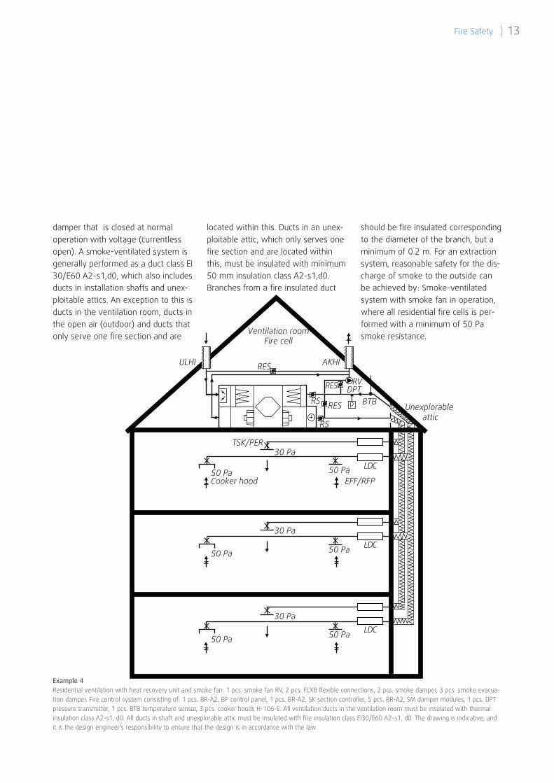
damper that is closed at normal operation with voltage (currentless open). A smoke-ventilated system is generally performed as a duct class EI 30/E60 A2-s1,d0, which also includes ducts in installation shafts and unex-ploitable attics. An exception to this is ducts in the ventilation room, ducts in the open air (outdoor) and ducts that only serve one fire section and are
located within this. Ducts in an unex-ploitable attic, which only serves one fire section and are located within this, must be insulated with minimum 50 mm insulation class A2-s1,d0. Branches from a fire insulated duct
should be fire insulated corresponding to the diameter of the branch, but a minimum of 0.2 m. For an extraction system, reasonable safety for the dis-charge of smoke to the outside can be achieved by: Smoke-ventilated system with smoke fan in operation, where all residential fire cells is per-formed with a minimum of 50 Pa smoke resistance.
Example 4Residential ventilation with heat recovery unit and smoke fan: 1 pcs. smoke fan RV, 2 pcs. FLXB flexible connections, 2 pcs. smoke damper, 3 pcs. smoke evacua-tion damper. Fire control system consisting of: 1 pcs. BR-A2, BP control panel, 1 pcs. BR-A2, SK section controller, 5 pcs. BR-A2, SM damper modules, 1 pcs. DPT pressure transmitter, 1 pcs. BTB temperature sensor, 3 pcs. cooker hoods H-106-E. All ventilation ducts in the ventilation room must be insulated with thermal insulation class A2-s1, d0. All ducts in shaft and unexplorable attic must be insulated with fire insulation class EI30/E60 A2-s1, d0. The drawing is indicative, and it is the design engineer’s responsibility to ensure that the design is in accordance with the law.
RS
RS
RES
RES
RES
Ventilation roomFire cell
Unexplorable attic
AKHIULHI
RV
30 Pa
50 Pa
50 Pa
50 Pa50 Pa
50 Pa
50 PaCooker hood EFF/RFP
DPT
TSK/PER
30 Pa
30 Pa
p BTB
LDC
LDC
LDC
13 Fire Safety |
Excerpts from DS 428.4Smoke-ventilated system
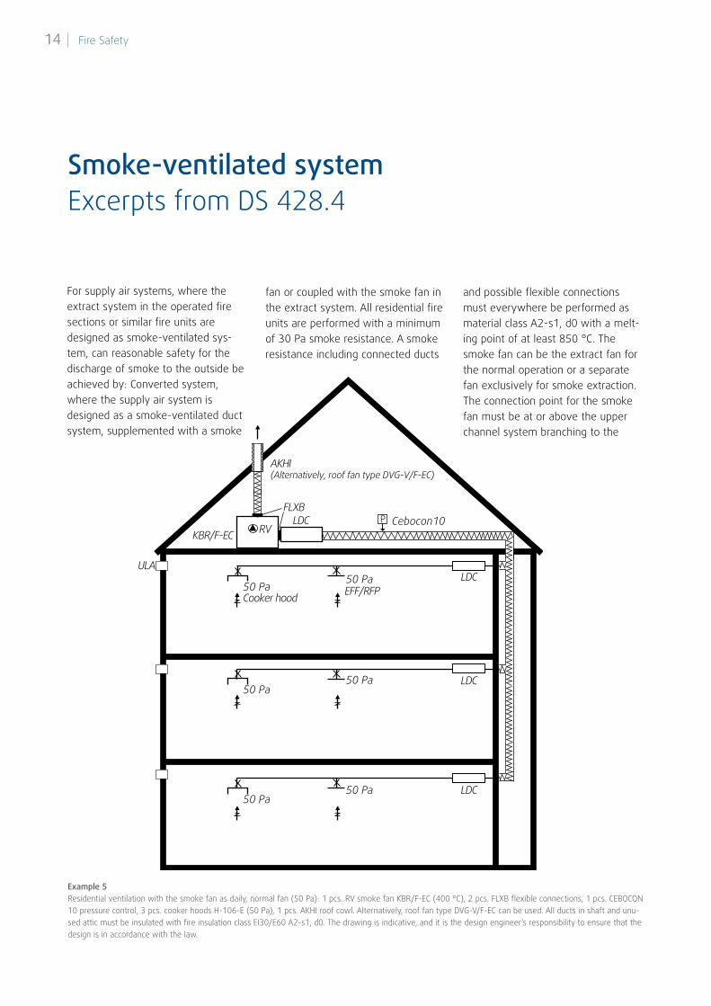
For supply air systems, where the extract system in the operated fire sections or similar fire units are designed as smoke-ventilated sys-tem, can reasonable safety for the discharge of smoke to the outside be achieved by: Converted system, where the supply air system is designed as a smoke-ventilated duct system, supplemented with a smoke
fan or coupled with the smoke fan in the extract system. All residential fire units are performed with a minimum of 30 Pa smoke resistance. A smoke resistance including connected ducts
and possible flexible connections must everywhere be performed as material class A2-s1, d0 with a melt-ing point of at least 850 °C. The smoke fan can be the extract fan for the normal operation or a separate fan exclusively for smoke extraction. The connection point for the smoke fan must be at or above the upper channel system branching to the
RV
50 Pa
50 Pa
50 Pa
50 Pa
50 Pa
50 Pa
FLXBLDC
KBR/F-EC
AKHI(Alternatively, roof fan type DVG-V/F-EC)
LDC
LDC
LDC
ULA
EFF/RFPCooker hood
Cebocon10P
Example 5Residential ventilation with the smoke fan as daily, normal fan (50 Pa): 1 pcs. RV smoke fan KBR/F-EC (400 °C), 2 pcs. FLXB flexible connections, 1 pcs. CEBOCON 10 pressure control, 3 pcs. cooker hoods H-106-E (50 Pa), 1 pcs. AKHI roof cowl. Alternatively, roof fan type DVG-V/F-EC can be used. All ducts in shaft and unu-sed attic must be insulated with fire insulation class EI30/E60 A2-s1, d0. The drawing is indicative, and it is the design engineer’s responsibility to ensure that the design is in accordance with the law.
| Fire Safety14
100 Pa
Cooker hoodEFF/RFP
100 Pa
100 Pa
100 Pa
P
Disc
harg
e du
ct
FLXB
KVKE-EC
LDC
LDC
LDC
AKHI Exhaust over roof ridge
Cebocon5
ULA
ULA
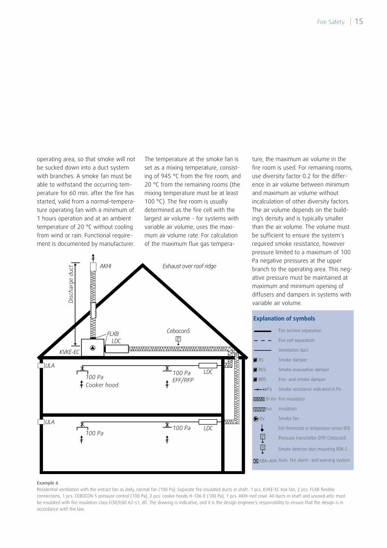
operating area, so that smoke will not be sucked down into a duct system with branches. A smoke fan must be able to withstand the occurring tem-perature for 60 min. after the fire has started, valid from a normal-tempera-ture operating fan with a minimum of 1 hours operation and at an ambient temperature of 20 °C without cooling from wind or rain. Functional require-ment is documented by manufacturer.
The temperature at the smoke fan is set as a mixing temperature, consist-ing of 945 °C from the fire room, and 20 °C from the remaining rooms (the mixing temperature must be at least 100 °C). The fire room is usually determined as the fire cell with the largest air volume - for systems with variable air volume, uses the maxi-mum air volume rate. For calculation of the maximum flue gas tempera-
ture, the maximum air volume in the fire room is used. For remaining rooms, use diversity factor 0.2 for the differ-ence in air volume between minimum and maximum air volume without incalculation of other diversity factors. The air volume depends on the build-ing’s density and is typically smaller than the air volume. The volume must be sufficient to ensure the system´s required smoke resistance, however pressure limited to a maximum of 100 Pa negative pressures at the upper branch to the operating area. This neg-ative pressure must be maintained at maximum and minimum opening of diffusers and dampers in systems with variable air volume.
Explanation of symbols
Fire section separation
Fire cell separation
Ventilation duct
Smoke damper
Smoke evacuation damper
Fire- and smoke damper
Smoke resistance indicated in Pa
Fire insulation
Insulation
Smoke fan
Fire thermostat or temperature sensor BTB
Pressure transmitter DTP, Cebocon5
Smoke detector duct mounting RDK-2
Auto. fire alarm- and warning system
RS
RES
BRS
Pa
B-iso
Iso
RV
ABA+AVA
P
R
x xx
Example 6Residential ventilation with the extract fan as daily, normal fan (100 Pa). Separate fire insulated ducts in shaft: 1 pcs. KVKE-EC box fan, 2 pcs. FLXB flexible connections, 1 pcs. CEBOCON 5 pressure control (100 Pa), 2 pcs. cooker hoods H-106-E (100 Pa), 1 pcs. AKHI roof cowl. All ducts in shaft and unused attic must be insulated with fire insulation class EI30/E60 A2-s1, d0. The drawing is indicative, and it is the design engineer’s responsibility to ensure that the design is in accordance with the law.
15 Fire Safety |
Systemair A/S DenmarkVed Milepælen 7DK-8361 Hasselager
Tel. +45 87 38 75 00
Bran
dsik
ring_
uk_0
4_20
13-V
1