Embed Size (px)
Citation preview
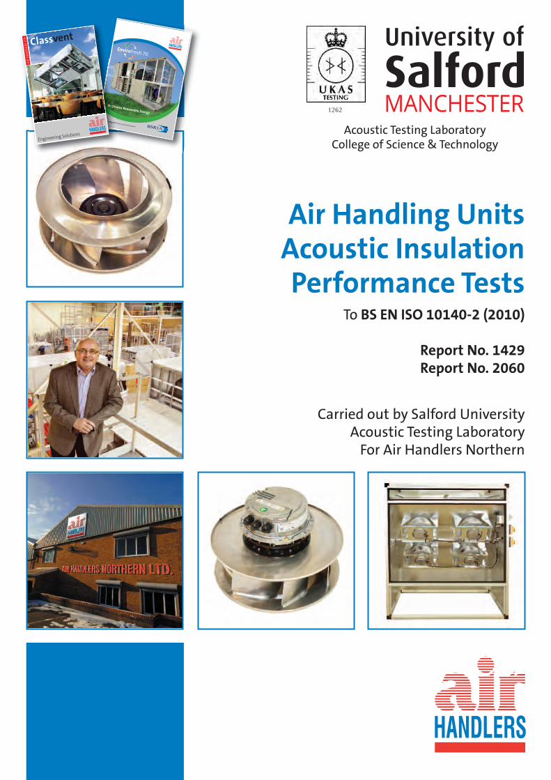
Air Handling UnitsAcoustic InsulationPerformance Tests
To BS EN ISO 10140-2 (2010)
Report No. 1429Report No. 2060
Carried out by Salford UniversityAcoustic Testing Laboratory
For Air Handlers Northern
1262
Acoustic Testing LaboratoryCollege of Science & Technology
Low Energy, Air Source, Heat Pump System
Air Source Renewable Energy
Classvent
Engineering Solutions
AIR
HA
ND
LER
S LT
D
SOUND REDUCTION INDEX FRAME & PANEL TESTS
Carried out by: - The University of Salford Acoustic Testing Laboratory Personnel: - Daniel McCaul Technical Manager Ian Rattigan Laboratory Manager David Pinchbeck Air Handlers Northern Report No 1429 and 2060 OBJECTIVE To obtain the true casework noise breakout from Mechanical Ventilation Plant. It is only possible to achieve this if the frame and panel assembly is tested with a large enough area sample to give a true representation of an Air Handling System. In Practice the framework can leak sound which will flank the panels; therefore our testing programme includes various frame insulation arrangements.
Page 1
Air Handling Unit Acoustic Insulation Performance Tests Air Handlers
Page 2
Air Handling Unit Acoustic Insulation Performance Tests Air Handlers
Page 3
Air Handling Unit Acoustic Insulation Performance Tests Air Handlers
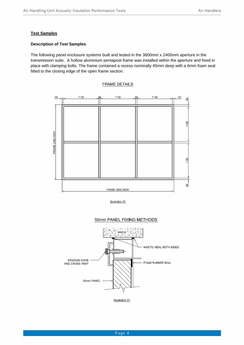
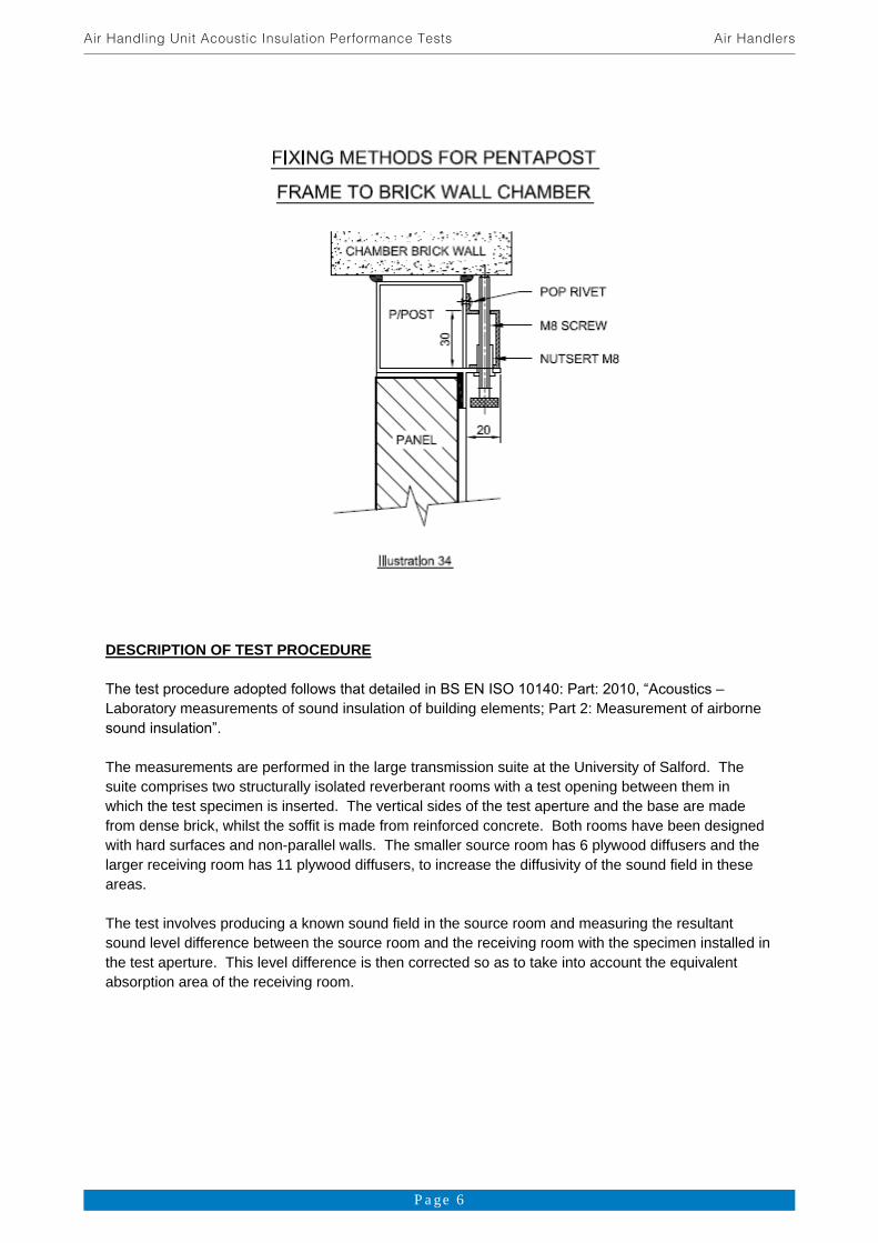
Test Samples Description of Test Samples The following panel enclosure systems built and tested in the 3600mm x 2400mm aperture in the transmission suite. A hollow aluminium pentapost frame was installed within the aperture and fixed in place with clamping bolts. The frame contained a recess nominally 45mm deep with a 6mm foam seal fitted to the closing edge of the open frame section.
Page 4
Air Handling Unit Acoustic Insulation Performance Tests Air Handlers
Page 5
Air Handling Unit Acoustic Insulation Performance Tests Air Handlers
DESCRIPTION OF TEST PROCEDURE
Laboratory measurements of sound insulation of building elements; Part 2: Measurement of airborne
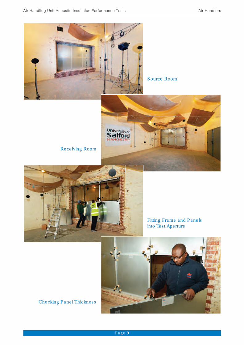
The measurements are performed in the large transmission suite at the University of Salford. The suite comprises two structurally isolated reverberant rooms with a test opening between them in which the test specimen is inserted. The vertical sides of the test aperture and the base are made from dense brick, whilst the soffit is made from reinforced concrete. Both rooms have been designed with hard surfaces and non-parallel walls. The smaller source room has 6 plywood diffusers and the larger receiving room has 11 plywood diffusers, to increase the diffusivity of the sound field in these areas. The test involves producing a known sound field in the source room and measuring the resultant sound level difference between the source room and the receiving room with the specimen installed in the test aperture. This level difference is then corrected so as to take into account the equivalent absorption area of the receiving room.
Page 6
Air Handling Unit Acoustic Insulation Performance Tests Air Handlers
The Sound Reduction Index, R (dB), is defined in BS EN SIO 10140 Part 2: 2010 as:
R = L1 L2 + 10 log10 (1)
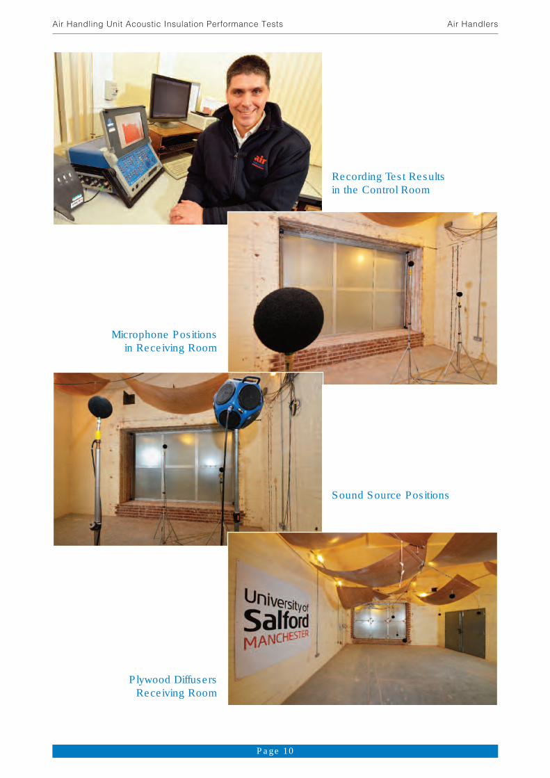
Where: L1 is the average sound pressure level in the source room (dB) L2 is the average sound pressur level in the receiving room (dB) S is the area of the rest specimen (m2) A is the equivalent absorption area of the receiving room (m2) Generation of Sound Field in the Source Room Wide band, random noise from the generator in the real time analyser was amplified and reproduced in the source room using alternately one of two fixed loudspeaker systems, (La, Lb and Lc). Omni-directional loudspeakers were used. The output of the generator was set with the intention that the sound pressure level in the receiving room was at least 15dB higher than the background level in any frequency band. The loudspeakers were positioned in the corners of the room and at such a distance from the test specimen that the direct radiation upon it was not dominant. Frequency Range of Measurements The sound pressure levels were measured using one-third octave band filters. Measurements covered all the one-third octave bands having centre frequencies in the range from 50Hz to 5000Hz. At the request of the client, measurements were also taken at the one-third octave band frequencies 6.3 kHz, 8 kHz and 10 kHz. The sound reduction indices at these additional frequencies are presented in Appendix A. Measurement of Sound Pressure Levels Sound pressure levels were measured simultaneously in the source and receiving rooms using loudspeaker La as the sound source. Measurements were recorded at a minimum of 5 fixed microphone positions in each room, using an averaging time of 32 seconds and the average level in each room was calculated on an energy basis in each one-third octave frequency band. The procedure was then repeated with loudspeaker Lb and Lc as the sound source. The overall average level difference in each frequency band was then calculated as the arithmetic average of the two sets of results. For each set of microphone/loudspeaker positions, the distances separating microphones from other microphones, room boundaries and diffusers, were greater than 0.7m and the distances separating microphones from the sound source and the test specimen were greater than 1m. Measurement and Evaluation of the Equivalent Absorption Areas The correction term of equation (1) containing the equivalent absorption area, A, was evaluated from
A = (2)
Where: V is the volume of the receiving room (m3) T is the reverberation time (s)
Page 7
Air Handling Unit Acoustic Insulation Performance Tests Air Handlers

The reverberation time of the receiving room was measured using a decay technique. The decays were produced by exciting the room with wide band random noise and stopping the excitation once the room became saturated. The resulting decaying sound field was monitored at 6 fixed microphone positions using a one-third octave band real time analyser. The sound spectrum was sampled at 32 millisecond intervals and stored in memory. Five decays were measured at each microphone position and averaged. The time taken for the sound to decay by 20dB was measured and multiplied by three to give the reverberation time. The measurements were repeated using an alternative sound source. The results from each set of position were averaged (ie 60 reverberation decays at each frequency). EQUIPMENT Departmental Record No Norwegian Electronics 1/3 octave band real time analyser type 840 with in-built random noise generator RTA2 Quad 510 power amplifier PA7 2 of omni-directional broadband loudspeakers (source room) LS10-LS11 2 of broadband loudspeakers (receiving room) LS3-LS4 3 of Bruel & Kjaer random incidence condenser microphones type 4166 in the source room M2-M4 3 of G.R.A.S. random incidence condenser microphones type 40AP in the source room M21,M22,M25 5 of Brunel & Kjaer random incidence condenser microphone M7-M9 type 4166 in the receiving room M18, M19 1 if G.R.A.S. random incidence condenser microphones type 40AP in the receiving room M20 2 of Norsonic Multiplexers type 834A MP1-MP2 HP Brio Pentium personal computer and related peripheral equipment COM6 (printer, plotter, monitor etc.) Yamaha GQ1031BII graphic equalizer GEQ1 RESULTS The sound reduction indices at one-third octave band intervals, R, are given in the tables overleaf. Source room volume: 136m3
Receiving room volume: 220m3 Sample sizes: 2400mm x 3600mm
Page 8
Air Handling Unit Acoustic Insulation Performance Tests Air Handlers
Page 9
Air Handling Unit Acoustic Insulation Performance Tests Air Handlers
Source Room
Fitting Frame and Panelsinto Test Aperture
Receiving Room
Checking Panel Thickness
Page 10
Air Handling Unit Acoustic Insulation Performance Tests Air Handlers
Recording Test Resultsin the Control Room
Sound Source Positions
Microphone Positionsin Receiving Room
Plywood Diffusers Receiving Room

SALFORD UNIVERSITY TEST REPORT 1429
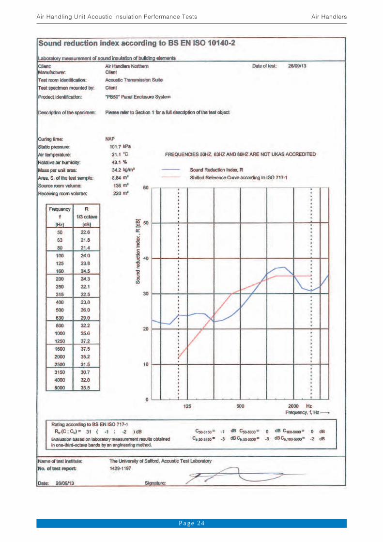
The following enclosure panels, consisting of a layered core (described from receiver to source room) contained within two 0.7mm steel cassettes of a number of thicknesses; were then installed into the open sections and fixed in place using toggles located on the frame on the receiving room side of the system. All units reported are nominal unless otherwise stated. Test A Test Reference: 1429-1197 Sample Reference: Sample Description: 45mm thick panel with a core consisting of four layers. The mass per unit
area of one panel was measured to be equal to 34.2kg/m2.
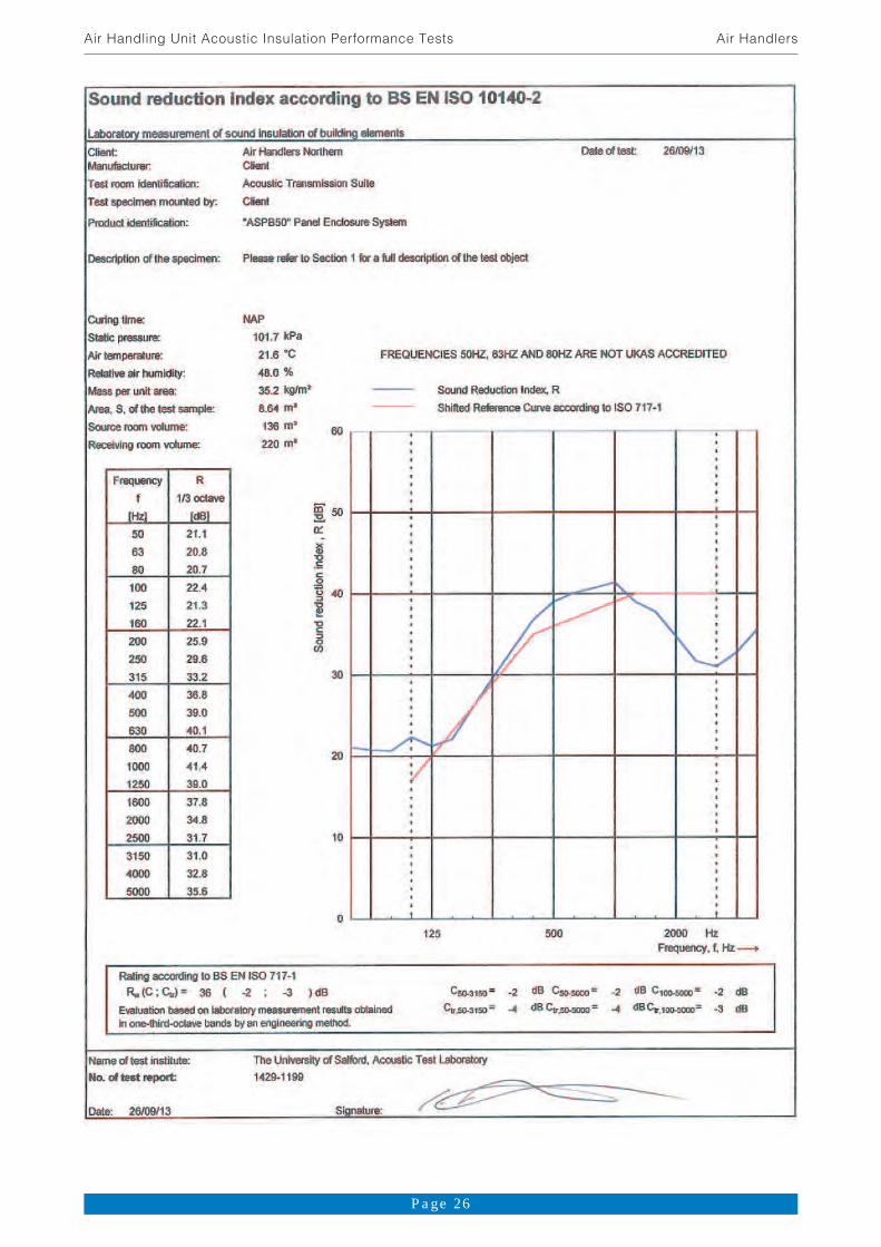
Test B Test Reference: 1429-1199 Sample Reference: Sample Description: 45mm thick panel with a core consisting of three layers. The mass per unit
area of one panel was measured to be equal to 35.2kg/m2. Test C Test Reference: 1429-1200 Sample Reference: Sample Description: 45mm thick panel with a core consisting of three layers. The mass per unit
area of one panel was measured to be equal to 45.6kg/m2. Test D Test Reference: 1429-1201 Sample Reference: Sample Description: 45mm thick panel with a core consisting of three layers. The mass per unit
area of one panel was measured to be equal to 38.1 kg/m2. Test E Test Reference: 1429-1203 Sample Reference: Sample Description: Modifications were made by fixing Acoustic Barrier Insulation to the source
room side of the frame.
Page 11
Air Handling Unit Acoustic Insulation Performance Tests Air Handlers

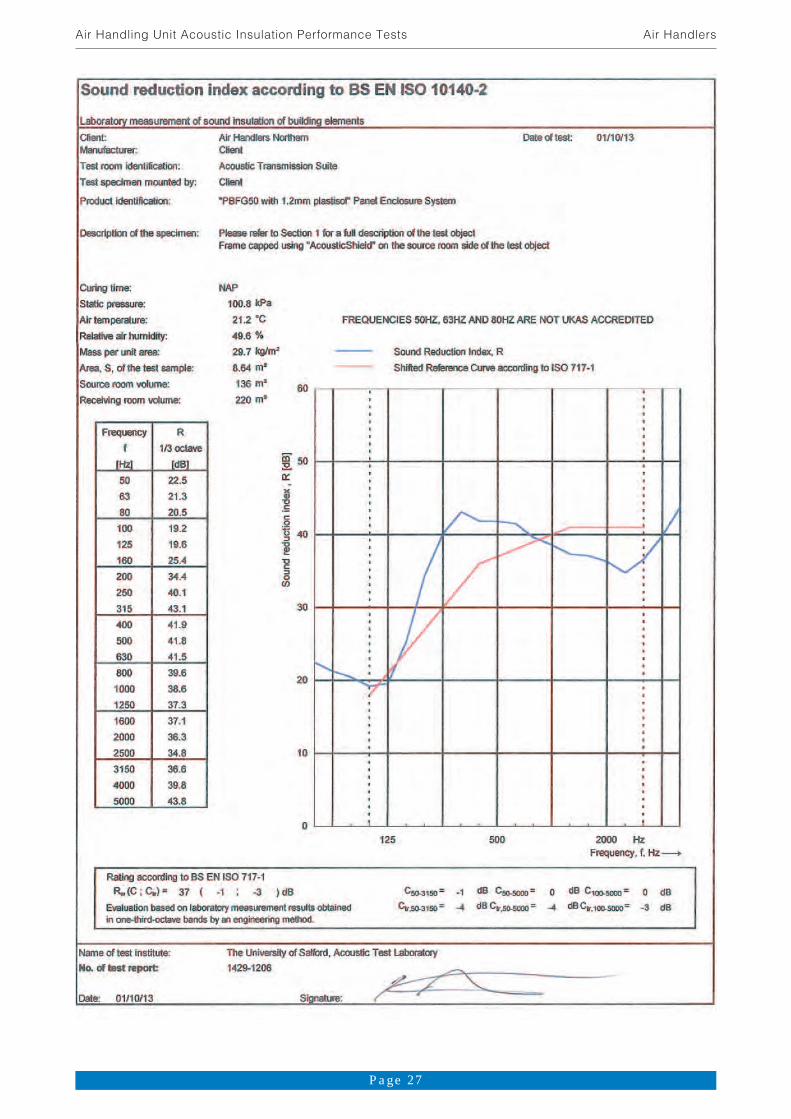
Test F Test Reference: 1429-1206 Sample Reference: Sample Description: 45mm thick panel with a core consisting of three layers. The steel cassette
on the source side of the system under test was replaced by a 1.2mm plastisol cassette. The mass per unit area of one panel was measured to be equal to 29.7kg/m2.
Test G Test Reference: 1429-1208 Sample Reference: Sample Description: 25mm thick panel with a core consisting of two layers. Profile sections were
used to provide secure fitting between the panel and the frame toggles. The mass per unit area of one panel was measured to be equal to 22.2kg/m2.
TEST RESULTS TO BS EN ISO 10140-2(2010)
Certified by: Salford University Acoustic Testing Laboratory
Also given in the attached tables and computed from the one-third octave band sound reduction indices, is the weighted sound reduction index, Rw, calculated according to ISO 717/1-1996. This evaluation is based on laboratory measurement results obtained by an engineering method. APPENDIX A
kHz, 8 kHz and 10 kHz, the results of which are presented below.
Test Reference
Sound Reduction Index, R [dB] 6.3 kHz 8 kHz 10 kHz
1429-1197 39.81 40.11 32.62
1429-1199 40.01 40.21 32.92
1429-1200 34.5 24.3 7.4 1429-1201 39.9 40.1 35.51
1429-1203 48.21 46.91 37.12
1429-1206 48.31 47.41 36.32
1429-1208 46.31 45.41 35.22
1 Correction for background applied to the result
2 Background levels too high minimum value for R.
Page 12
Air Handling Unit Acoustic Insulation Performance Tests Air Handlers
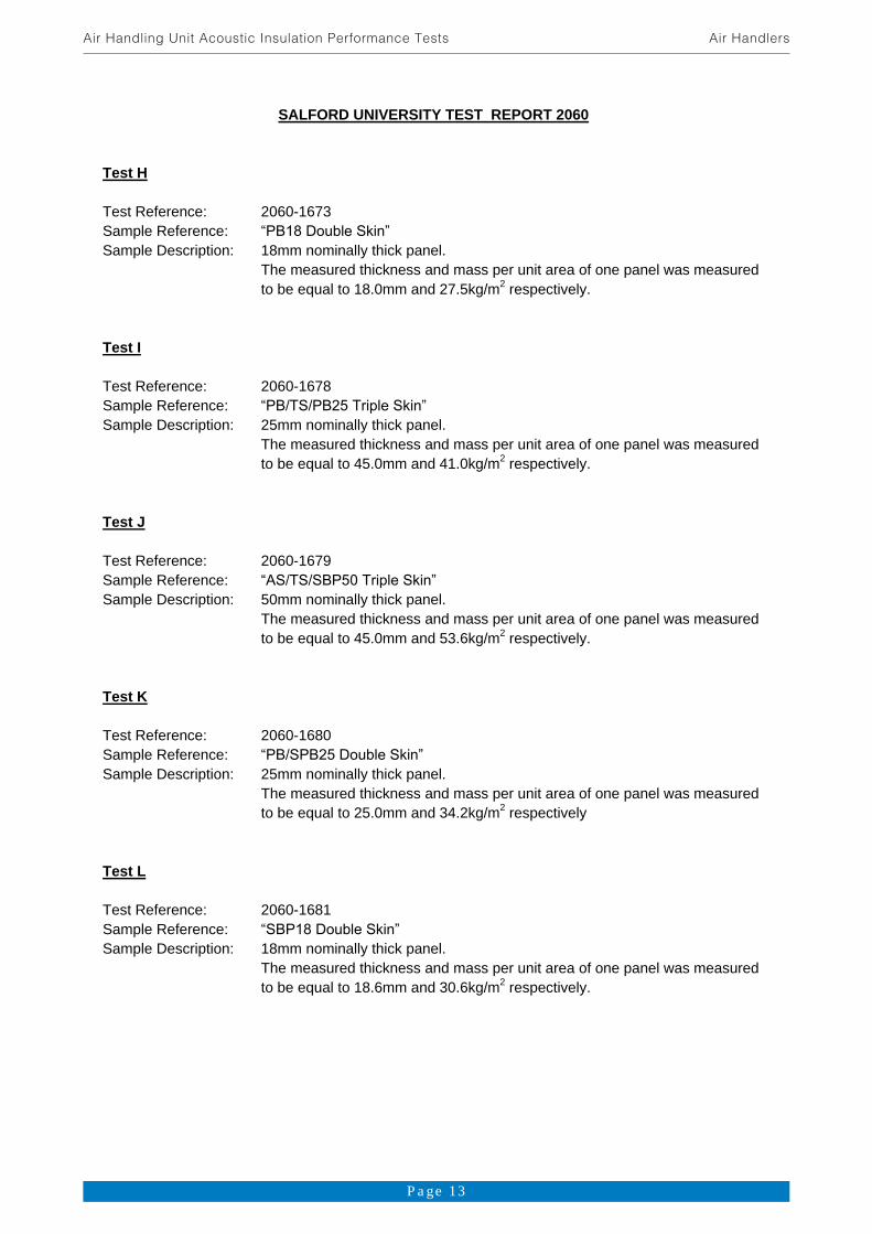
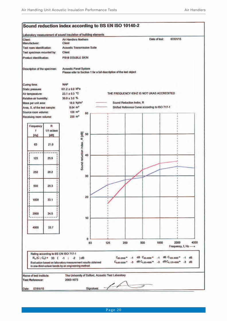
SALFORD UNIVERSITY TEST REPORT 2060 Test H Test Reference: 2060-1673 Sample Reference: Sample Description: 18mm nominally thick panel.
The measured thickness and mass per unit area of one panel was measured to be equal to 18.0mm and 27.5kg/m2 respectively.
Test I Test Reference: 2060-1678 Sample Reference: Sample Description: 25mm nominally thick panel.
The measured thickness and mass per unit area of one panel was measured to be equal to 45.0mm and 41.0kg/m2 respectively.
Test J Test Reference: 2060-1679 Sample Reference: Sample Description: 50mm nominally thick panel.
The measured thickness and mass per unit area of one panel was measured to be equal to 45.0mm and 53.6kg/m2 respectively.
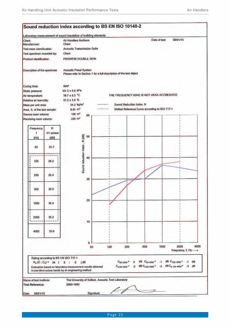
Test K Test Reference: 2060-1680 Sample Reference: Sample Description: 25mm nominally thick panel.
The measured thickness and mass per unit area of one panel was measured to be equal to 25.0mm and 34.2kg/m2 respectively
Test L Test Reference: 2060-1681 Sample Reference: Sample Description: 18mm nominally thick panel.
The measured thickness and mass per unit area of one panel was measured to be equal to 18.6mm and 30.6kg/m2 respectively.
Page 13
Air Handling Unit Acoustic Insulation Performance Tests Air Handlers
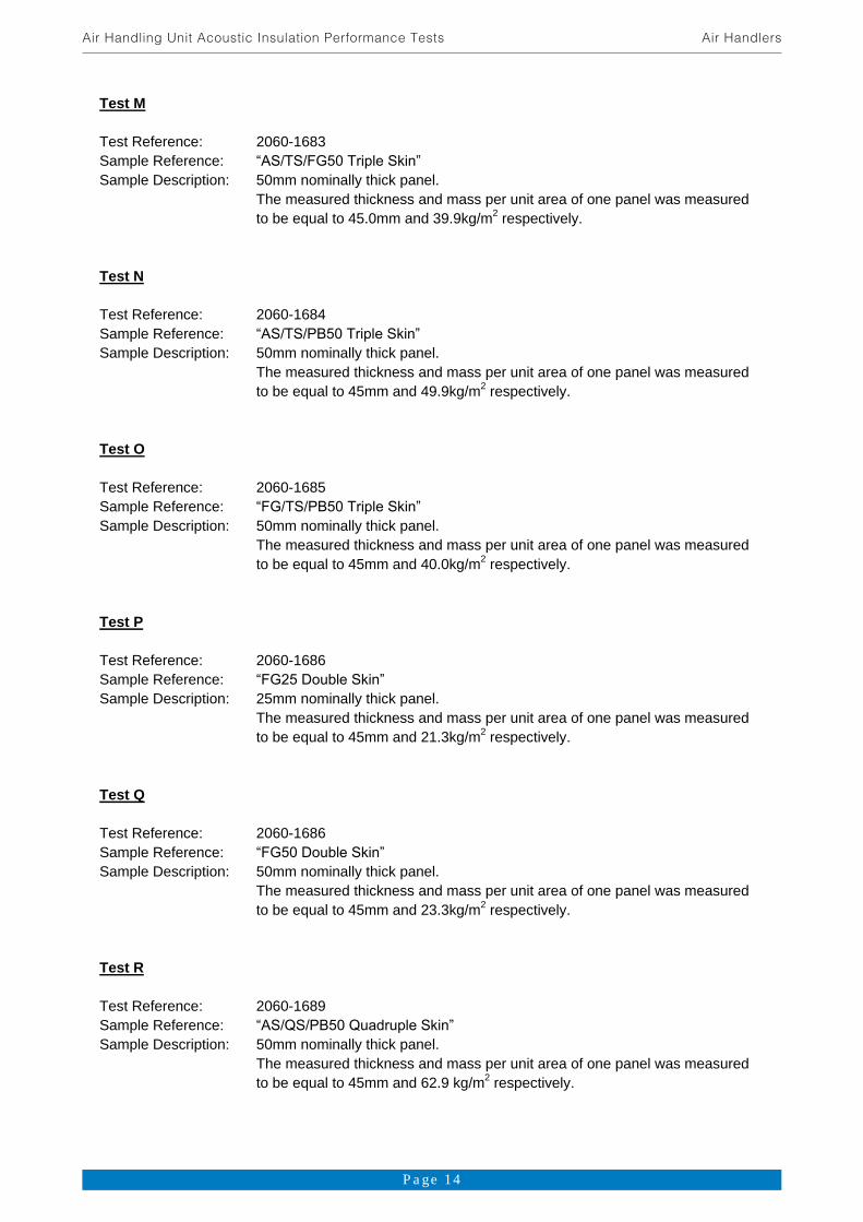
Test M Test Reference: 2060-1683 Sample Reference: Sample Description: 50mm nominally thick panel.
The measured thickness and mass per unit area of one panel was measured to be equal to 45.0mm and 39.9kg/m2 respectively.
Test N Test Reference: 2060-1684 Sample Reference: Sample Description: 50mm nominally thick panel.
The measured thickness and mass per unit area of one panel was measured to be equal to 45mm and 49.9kg/m2 respectively.
Test O Test Reference: 2060-1685 Sample Reference: Sample Description: 50mm nominally thick panel.
The measured thickness and mass per unit area of one panel was measured to be equal to 45mm and 40.0kg/m2 respectively.
Test P Test Reference: 2060-1686 Sample Reference: Sample Description: 25mm nominally thick panel.
The measured thickness and mass per unit area of one panel was measured to be equal to 45mm and 21.3kg/m2 respectively.
Test Q Test Reference: 2060-1686 Sample Reference: Sample Description: 50mm nominally thick panel.
The measured thickness and mass per unit area of one panel was measured to be equal to 45mm and 23.3kg/m2 respectively.
Test R Test Reference: 2060-1689 Sample Reference: Sample Description: 50mm nominally thick panel.
The measured thickness and mass per unit area of one panel was measured to be equal to 45mm and 62.9 kg/m2 respectively.
Page 14
Air Handling Unit Acoustic Insulation Performance Tests Air Handlers

Test S Test Reference: 2060-1675 Sample Reference: Sample Description: 18mm nominally thick panel.
The measured thickness and mass per unit area of one panel was measured to be equal to 18.0mm and 20.9kg/m2 respectively.
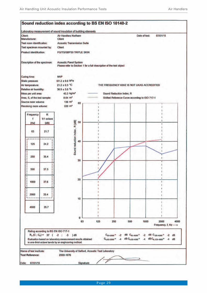
Test T Test Reference: 2060-1676 Sample Reference: Sample Description: 50mm nominally thick panel.
The measured thickness and mass per unit area of one panel was measured to be equal to 45mm and 43.3kg/m2 respectively.
Test U Test Reference: 2060-1674 Sample Reference: Sample Description: 25mm nominally thick panel.
The measured thickness and mass per unit area of one panel was measured to be equal to 30.3mm and 31.3kg/m2 respectively.
Page 15
Air Handling Unit Acoustic Insulation Performance Tests Air Handlers
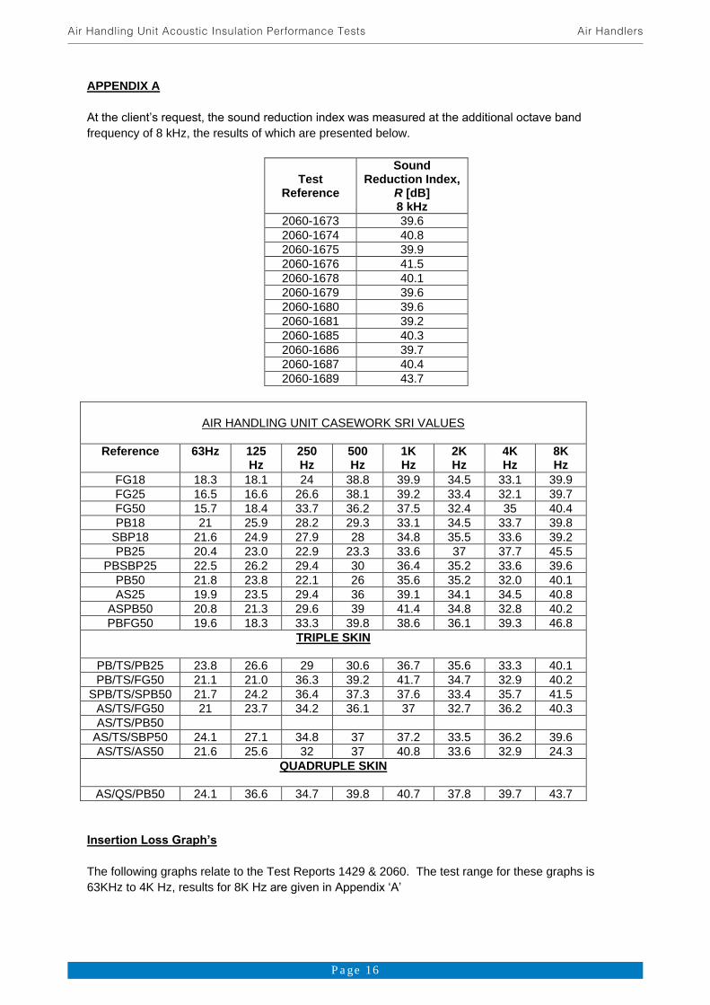
APPENDIX A
frequency of 8 kHz, the results of which are presented below.
Test
Reference
Sound Reduction Index,
R [dB] 8 kHz
2060-1673 39.6 2060-1674 40.8 2060-1675 39.9 2060-1676 41.5 2060-1678 40.1 2060-1679 39.6 2060-1680 39.6 2060-1681 39.2 2060-1685 40.3 2060-1686 39.7 2060-1687 40.4 2060-1689 43.7
AIR HANDLING UNIT CASEWORK SRI VALUES
Reference 63Hz 125 Hz
250 Hz
500 Hz
1K Hz
2K Hz
4K Hz
8K Hz
FG18 18.3 18.1 24 38.8 39.9 34.5 33.1 39.9 FG25 16.5 16.6 26.6 38.1 39.2 33.4 32.1 39.7 FG50 15.7 18.4 33.7 36.2 37.5 32.4 35 40.4 PB18 21 25.9 28.2 29.3 33.1 34.5 33.7 39.8
SBP18 21.6 24.9 27.9 28 34.8 35.5 33.6 39.2 PB25 20.4 23.0 22.9 23.3 33.6 37 37.7 45.5
PBSBP25 22.5 26.2 29.4 30 36.4 35.2 33.6 39.6 PB50 21.8 23.8 22.1 26 35.6 35.2 32.0 40.1 AS25 19.9 23.5 29.4 36 39.1 34.1 34.5 40.8
ASPB50 20.8 21.3 29.6 39 41.4 34.8 32.8 40.2 PBFG50 19.6 18.3 33.3 39.8 38.6 36.1 39.3 46.8
TRIPLE SKIN
PB/TS/PB25 23.8 26.6 29 30.6 36.7 35.6 33.3 40.1 PB/TS/FG50 21.1 21.0 36.3 39.2 41.7 34.7 32.9 40.2
SPB/TS/SPB50 21.7 24.2 36.4 37.3 37.6 33.4 35.7 41.5 AS/TS/FG50 21 23.7 34.2 36.1 37 32.7 36.2 40.3 AS/TS/PB50
AS/TS/SBP50 24.1 27.1 34.8 37 37.2 33.5 36.2 39.6 AS/TS/AS50 21.6 25.6 32 37 40.8 33.6 32.9 24.3
QUADRUPLE SKIN
AS/QS/PB50 24.1 36.6 34.7 39.8 40.7 37.8 39.7 43.7
The following graphs relate to the Test Reports 1429 & 2060. The test range for these graphs is 63KHz to 4K Hz, results for 8K
Page 16
Air Handling Unit Acoustic Insulation Performance Tests Air Handlers

Page 17
Air Handling Unit Acoustic Insulation Performance Tests Air Handlers

Page 18
Air Handling Unit Acoustic Insulation Performance Tests Air Handlers
Page 19
Air Handling Unit Acoustic Insulation Performance Tests Air Handlers
Page 20
Air Handling Unit Acoustic Insulation Performance Tests Air Handlers

Page 21
Air Handling Unit Acoustic Insulation Performance Tests Air Handlers

Page 22
Air Handling Unit Acoustic Insulation Performance Tests Air Handlers
Page 23
Air Handling Unit Acoustic Insulation Performance Tests Air Handlers
Page 24
Air Handling Unit Acoustic Insulation Performance Tests Air Handlers

Page 25
Air Handling Unit Acoustic Insulation Performance Tests Air Handlers
Page 26
Air Handling Unit Acoustic Insulation Performance Tests Air Handlers
Page 27
Air Handling Unit Acoustic Insulation Performance Tests Air Handlers

Page 28
Air Handling Unit Acoustic Insulation Performance Tests Air Handlers
Page 29
Air Handling Unit Acoustic Insulation Performance Tests Air Handlers

Page 30
Air Handling Unit Acoustic Insulation Performance Tests Air Handlers

Page 31
Air Handling Unit Acoustic Insulation Performance Tests Air Handlers

Page 32
Air Handling Unit Acoustic Insulation Performance Tests Air Handlers

Page 33
Air Handling Unit Acoustic Insulation Performance Tests Air Handlers

Page 34
Air Handling Unit Acoustic Insulation Performance Tests Air Handlers
Page 35
Air Handling Unit Acoustic Insulation Performance Tests Air Handlers
Notes

Page 36
Air Handling Unit Acoustic Insulation Performance Tests Air Handlers
Notes