Embed Size (px)
Citation preview
air avionics
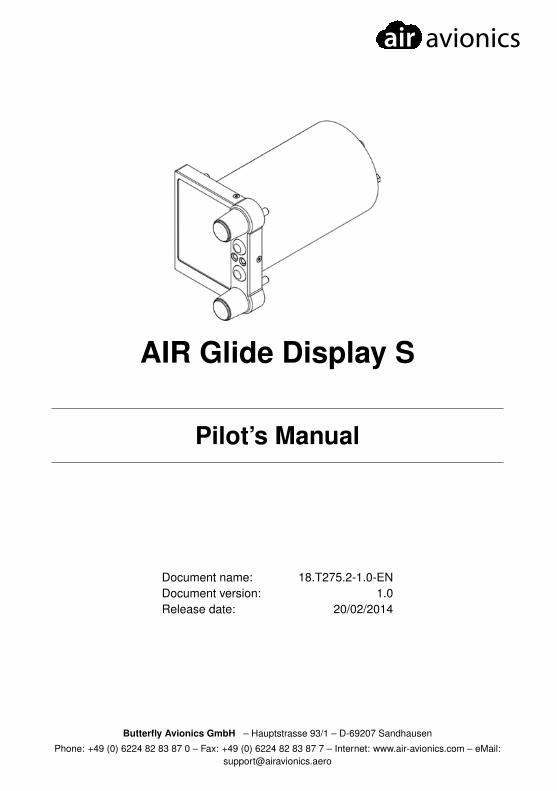
AIR Glide Display S
Pilot’s Manual
Document name: 18.T275.2-1.0-ENDocument version: 1.0Release date: 20/02/2014
Butterfly Avionics GmbH – Hauptstrasse 93/1 – D-69207 Sandhausen
Phone: +49 (0) 6224 82 83 87 0 – Fax: +49 (0) 6224 82 83 87 7 – Internet: www.air-avionics.com – eMail:[email protected]

air avionics
Notes
i Display S Pilot’s Manual • 18.T275.2-1.0-EN
air avionics
General Information
IMPORTANT!
Please read this manual carefully before installing or operating the device!
Pay attention to the restrictions on use!
This manual is an essential part of the device and must be kept in a safe place!
Document identification / revision statusThis manual supports the following product types:
• P/N T275 ”AIR Glide Display S”
Actual version: Display S Pilot’s Manual • 18.T275.2-1.0-EN, Version 1.0(192)
Version history
Revision Date Status Author Changes, comments Approved1.0 Mai 2013 released M. Foerderer Translation from Ger-
man Manual-
1.0 July 2013 released M. Foerderer Corrections and addedfeatures of latest soft-ware version
-
1.6 October2013
released M. Foerderer added details -
1.6 FEB 2014 released M. Foerderer AIR Glide Branding -1.7 APR
2014released M. Foerderer added details -
Display S Pilot’s Manual • 18.T275.2-1.0-EN ii
CONTENTS air avionics
Contents1 General 1
1.1 System Description . . . . . . . . . . . . . . . . . . . . . . . . . . . . . . . 11.2 Design Goals . . . . . . . . . . . . . . . . . . . . . . . . . . . . . . . . . . . 1
2 Safety, Liability and Support 32.1 Safety instructions and restrictions on use . . . . . . . . . . . . . . . . . . . . 32.2 Intellectual Property and Liability . . . . . . . . . . . . . . . . . . . . . . . . 32.3 Support . . . . . . . . . . . . . . . . . . . . . . . . . . . . . . . . . . . . . . 3
2.3.1 World . . . . . . . . . . . . . . . . . . . . . . . . . . . . . . . . . . . . . 32.3.2 Europe . . . . . . . . . . . . . . . . . . . . . . . . . . . . . . . . . . . . 3
3 Operation And Controls 43.1 User Interface Elements . . . . . . . . . . . . . . . . . . . . . . . . . . . . . 4
3.1.1 Rotary Knobs And Pushuttons . . . . . . . . . . . . . . . . . . . . . . . . 43.1.2 Status-LED . . . . . . . . . . . . . . . . . . . . . . . . . . . . . . . . . . 4
3.2 Switching AIR Glide ON and OFF . . . . . . . . . . . . . . . . . . . . . . . . 43.2.1 Switching AIR Glide ON . . . . . . . . . . . . . . . . . . . . . . . . . . . 53.2.2 Switching AIR Glide OFF . . . . . . . . . . . . . . . . . . . . . . . . . . . 5
3.3 Display Pages . . . . . . . . . . . . . . . . . . . . . . . . . . . . . . . . . . 63.3.1 Page Navigation Indicator . . . . . . . . . . . . . . . . . . . . . . . . . . 6
3.4 Flight-Mode . . . . . . . . . . . . . . . . . . . . . . . . . . . . . . . . . . . 63.4.1 Sound-Scheme . . . . . . . . . . . . . . . . . . . . . . . . . . . . . . . . 73.4.2 Behavior when changing flight-mode . . . . . . . . . . . . . . . . . . . . . 7
3.5 Menu-System . . . . . . . . . . . . . . . . . . . . . . . . . . . . . . . . . . 83.5.1 Entering the Menu and Menu-Levels . . . . . . . . . . . . . . . . . . . . . 83.5.2 Types Of Menu Items . . . . . . . . . . . . . . . . . . . . . . . . . . . . . 83.5.3 Directly closing the Menu . . . . . . . . . . . . . . . . . . . . . . . . . . . 9
3.6 Text-Input . . . . . . . . . . . . . . . . . . . . . . . . . . . . . . . . . . . . . 10
4 Main Functions 114.1 Variometer . . . . . . . . . . . . . . . . . . . . . . . . . . . . . . . . . . . . 11
4.1.1 Variometer-Display-Page . . . . . . . . . . . . . . . . . . . . . . . . . . . 114.1.2 Vario Indicator And Pointers . . . . . . . . . . . . . . . . . . . . . . . . . 114.1.3 Vario indication On Other Display-Pages . . . . . . . . . . . . . . . . . . . 12
4.2 Speedcommand . . . . . . . . . . . . . . . . . . . . . . . . . . . . . . . . . 134.2.1 Speedcommand-display-page . . . . . . . . . . . . . . . . . . . . . . . . 134.2.2 Speedcommand Behavior . . . . . . . . . . . . . . . . . . . . . . . . . . 13
4.3 Traffic . . . . . . . . . . . . . . . . . . . . . . . . . . . . . . . . . . . . . . . 144.3.1 Traffic-Display-Page . . . . . . . . . . . . . . . . . . . . . . . . . . . . . 144.3.2 Status of connected collision warning units . . . . . . . . . . . . . . . . . 15
4.4 Navigation . . . . . . . . . . . . . . . . . . . . . . . . . . . . . . . . . . . . 154.4.1 Navigation-display-page . . . . . . . . . . . . . . . . . . . . . . . . . . . 154.4.2 Target Selection In Navigation . . . . . . . . . . . . . . . . . . . . . . . . 16
iii Display S Pilot’s Manual • 18.T275.2-1.0-EN
air avionics CONTENTS
4.4.3 Nearest Function . . . . . . . . . . . . . . . . . . . . . . . . . . . . . . . 174.4.4 Direct-To Function . . . . . . . . . . . . . . . . . . . . . . . . . . . . . . 17
4.5 Attitude and Heading Indicator . . . . . . . . . . . . . . . . . . . . . . . . . . 184.6 Flight Logging . . . . . . . . . . . . . . . . . . . . . . . . . . . . . . . . . . 20
4.6.1 Entering and declaring IGC Flight-Info and Tasks . . . . . . . . . . . . . . 204.6.2 Entering IGC Flight-Info . . . . . . . . . . . . . . . . . . . . . . . . . . . . 214.6.3 Declaring a Route/Flight-info . . . . . . . . . . . . . . . . . . . . . . . . . 214.6.4 Downloading Flights . . . . . . . . . . . . . . . . . . . . . . . . . . . . . 214.6.5 Flight Recorder Setup . . . . . . . . . . . . . . . . . . . . . . . . . . . . 224.6.6 IGC-Pilot-Event . . . . . . . . . . . . . . . . . . . . . . . . . . . . . . . . 22
4.7 Features that are not allowed in some competitions . . . . . . . . . . . . . . . 234.7.1 Possibly Unallowed Features . . . . . . . . . . . . . . . . . . . . . . . . . 23
4.8 Locking Unallowed Features / AHI Lock . . . . . . . . . . . . . . . . . . . . . 234.8.1 Required Firmware Versions . . . . . . . . . . . . . . . . . . . . . . . . . 234.8.2 Security . . . . . . . . . . . . . . . . . . . . . . . . . . . . . . . . . . . . 244.8.3 Locking the AHI . . . . . . . . . . . . . . . . . . . . . . . . . . . . . . . 244.8.4 Activating an AHI locking timeframe . . . . . . . . . . . . . . . . . . . . . 244.8.5 Behavior when AHI lock is active . . . . . . . . . . . . . . . . . . . . . . . 254.8.6 Determining if lock is active . . . . . . . . . . . . . . . . . . . . . . . . . . 25
4.9 Hardware and Data Monitoring . . . . . . . . . . . . . . . . . . . . . . . . . 254.9.1 Data Validity . . . . . . . . . . . . . . . . . . . . . . . . . . . . . . . . . 254.9.2 Powermanagement . . . . . . . . . . . . . . . . . . . . . . . . . . . . . . 26
5 Audio-System 275.1 Setting up volume . . . . . . . . . . . . . . . . . . . . . . . . . . . . . . . . 275.2 Audio-Menu . . . . . . . . . . . . . . . . . . . . . . . . . . . . . . . . . . . 275.3 Bass Boost Feature . . . . . . . . . . . . . . . . . . . . . . . . . . . . . . . 285.4 Vario/speedcommand Audio . . . . . . . . . . . . . . . . . . . . . . . . . . . 28
5.4.1 Sound-Scheme in Cruise-Mode . . . . . . . . . . . . . . . . . . . . . . . 285.4.2 Sound-Scheme in Climb-Mode . . . . . . . . . . . . . . . . . . . . . . . . 28
5.5 Voice Output . . . . . . . . . . . . . . . . . . . . . . . . . . . . . . . . . . . 295.5.1 Message Priorities . . . . . . . . . . . . . . . . . . . . . . . . . . . . . . 295.5.2 Messages . . . . . . . . . . . . . . . . . . . . . . . . . . . . . . . . . . . 295.5.3 Acknowledging Messages . . . . . . . . . . . . . . . . . . . . . . . . . . 305.5.4 Repeating Messages . . . . . . . . . . . . . . . . . . . . . . . . . . . . . 30
6 Setup 316.1 Setup of Flight-Paramters in Flight. . . . . . . . . . . . . . . . . . . . . . . . 316.2 Filter- and Compensation-Values . . . . . . . . . . . . . . . . . . . . . . . . 31
6.2.1 Filters and Recommended Values . . . . . . . . . . . . . . . . . . . . . . 316.3 Magnetometer-Compensation . . . . . . . . . . . . . . . . . . . . . . . . . . 32
6.3.1 Performing Magnetometer Compensation . . . . . . . . . . . . . . . . . . 326.3.2 Quality indicator . . . . . . . . . . . . . . . . . . . . . . . . . . . . . . . . 33
6.4 Individualization and Adaption . . . . . . . . . . . . . . . . . . . . . . . . . . 336.4.1 Language . . . . . . . . . . . . . . . . . . . . . . . . . . . . . . . . . . . 33
Display S Pilot’s Manual • 18.T275.2-1.0-EN iv
CONTENTS air avionics
6.4.2 Units . . . . . . . . . . . . . . . . . . . . . . . . . . . . . . . . . . . . . 336.4.3 Info-Boxes . . . . . . . . . . . . . . . . . . . . . . . . . . . . . . . . . . 336.4.4 Other settings . . . . . . . . . . . . . . . . . . . . . . . . . . . . . . . . . 34
6.5 Factory Reset . . . . . . . . . . . . . . . . . . . . . . . . . . . . . . . . . . 35
7 Maintenance and First Use 367.1 First Use . . . . . . . . . . . . . . . . . . . . . . . . . . . . . . . . . . . . . 36
7.1.1 Switching AIR Glide on the first time . . . . . . . . . . . . . . . . . . . . . 367.2 Required Settings . . . . . . . . . . . . . . . . . . . . . . . . . . . . . . . . 36
7.2.1 Before first flight . . . . . . . . . . . . . . . . . . . . . . . . . . . . . . . 367.2.2 Special settings when installing multiple displays . . . . . . . . . . . . . . 367.2.3 During first flight . . . . . . . . . . . . . . . . . . . . . . . . . . . . . . . 36
7.3 Softwareupdates . . . . . . . . . . . . . . . . . . . . . . . . . . . . . . . . . 377.3.1 Prepare an Update . . . . . . . . . . . . . . . . . . . . . . . . . . . . . . 377.3.2 Updating your Device . . . . . . . . . . . . . . . . . . . . . . . . . . . . . 37
7.4 Data Synchronization . . . . . . . . . . . . . . . . . . . . . . . . . . . . . . 387.4.1 Behavior . . . . . . . . . . . . . . . . . . . . . . . . . . . . . . . . . . . 387.4.2 File- and Datatypes . . . . . . . . . . . . . . . . . . . . . . . . . . . . . . 387.4.3 Synchronization . . . . . . . . . . . . . . . . . . . . . . . . . . . . . . . . 387.4.4 Navigation data . . . . . . . . . . . . . . . . . . . . . . . . . . . . . . . . 397.4.5 Downloading recorded flights . . . . . . . . . . . . . . . . . . . . . . . . . 39
8 Calculations and Informations 408.1 AHRS . . . . . . . . . . . . . . . . . . . . . . . . . . . . . . . . . . . . . . 408.2 Wind Calculation . . . . . . . . . . . . . . . . . . . . . . . . . . . . . . . . . 408.3 Speedcommand . . . . . . . . . . . . . . . . . . . . . . . . . . . . . . . . . 408.4 Vertical Air-Mass . . . . . . . . . . . . . . . . . . . . . . . . . . . . . . . . . 408.5 Final Glide Calculation . . . . . . . . . . . . . . . . . . . . . . . . . . . . . . 42
1 Display S Pilot’s Manual • 18.T275.2-1.0-EN
1 GENERAL air avionics
1 General
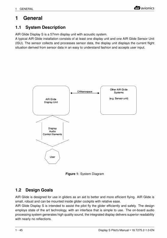
1.1 System DescriptionAIR Glide Display S is a 57mm display unit with acoustic system.A typical AIR Glide installation consists of at least one display unit and one AIR Glide Sensor Unit(ISU). The sensor collects and processes sensor data, the display unit displays the current flightsituation derived from sensor data in an easy to understand fashion and accepts user input.
Figure 1: System Diagram
1.2 Design GoalsAIR Glide is designed for use in gliders as an aid to better and more efficient flying. AIR Glide issmall, robust and can be mounted inside glider cockpits with relative ease.AIR Glide Display S is intended to assist the pilot fly the glider efficiently and safely. The designemploys state of the art technology, with an interface that is simple to use. The on-board audioprocessing system generates high quality sound, the integrated display delivers superior readabilitywith nearly no reflections.
1 - 45 Display S Pilot’s Manual • 18.T275.2-1.0-EN

air avionics 1 GENERAL
In many gliding accidents, pilot overload is known to be a contributing factor. Cross-country flying,competitions, busy airspace and flying in unfamiliar terrain can all cause a high pilot workloadfor long durations. A design goal of AIR Glide is to help relieve this situation by giving advisorymessages and alarms when the aircraft is not being flown safely or efficiently.
Display S Pilot’s Manual • 18.T275.2-1.0-EN 2 - 45
2 SAFETY, LIABILITY AND SUPPORT air avionics
2 Safety, Liability and Support
2.1 Safety instructions and restrictions on useInstallation and operation must be on the basis of non-interference with and no hazard to the exist-ing suite of other equipment necessary for safe flying operation, or installed to comply with officialrequirements. Installation and operation must comply with official regulations and requirements.
The pilot is ultimately responsible for all flight decisions and for operating the aircraftsafely at all times. For situational awareness only!
Never make safety critical decisions based displayed information.
AIR Glide Display S does not have a ETSO or FAA-TSO airworthiness certification.Make sure that it is legal to install it in your aircraft.
Do not use AIR Glide Display S if pilot-workload is increased by failure of AIR Glide orattached subsystems.
2.2 Intellectual Property and LiabilityButterfly Avionics GmbH, will not be liable for errors/changes/omissions in this document - specifi-cations are subject to change without notice. Butterfly Avionics its associates, development team,suppliers, manufacturers and data suppliers accept no responsibility for any damage or claims thatmay arise from use of AIR Glide.
Trademarks referred to in this document are the property of their respective holders. Any decom-piling, disassembly, reverse engineering, or modification of the instrument or firmware are strictlyprohibited without specific written permission from Butterfly Avionics GmbH.
2.3 Support
2.3.1 WorldTo get support, please contact your local authorized AIR Avionics dealer.
2.3.2 EuropePlease contact us via eMail or Phone. Find more information on www.air-avionics.com or +49 (0)6224 82 83 87 0
3 - 45 Display S Pilot’s Manual • 18.T275.2-1.0-EN
air avionics 3 OPERATION AND CONTROLS
3 Operation And Controls
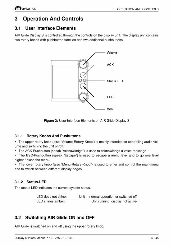
3.1 User Interface ElementsAIR Glide Display S is controlled through the controls on the display unit. The display unit containstwo rotary knobs with pushbutton function and two additional pushbuttons.
Figure 2: User Interface Elements on AIR Glide Display S
3.1.1 Rotary Knobs And Pushuttons• The upper rotary knob (also ”Volume-Rotary-Knob”) is mainly intended for controlling audio vol-ume and switching the unit on/off.• The ACK-Pushbutton (speak ”Acknowledge”) is used to acknowledge a voice-message• The ESC-Pushbutton (speak ”Escape”) is used to escape a menu level and to go one levelhigher / close the menu.• The lower rotary knob (also ”Menu-Rotary-Knob”) is used to enter and control the main-menuand to switch between different display-pages.
3.1.2 Status-LEDThe status LED indicates the current system status.
LED does not shine: Unit in normal operation or switched offLED shines amber: Unit running, display not active
3.2 Switching AIR Glide ON and OFF
AIR Glide is switched on and off using the upper rotary knob.
Display S Pilot’s Manual • 18.T275.2-1.0-EN 4 - 45
3 OPERATION AND CONTROLS air avionics
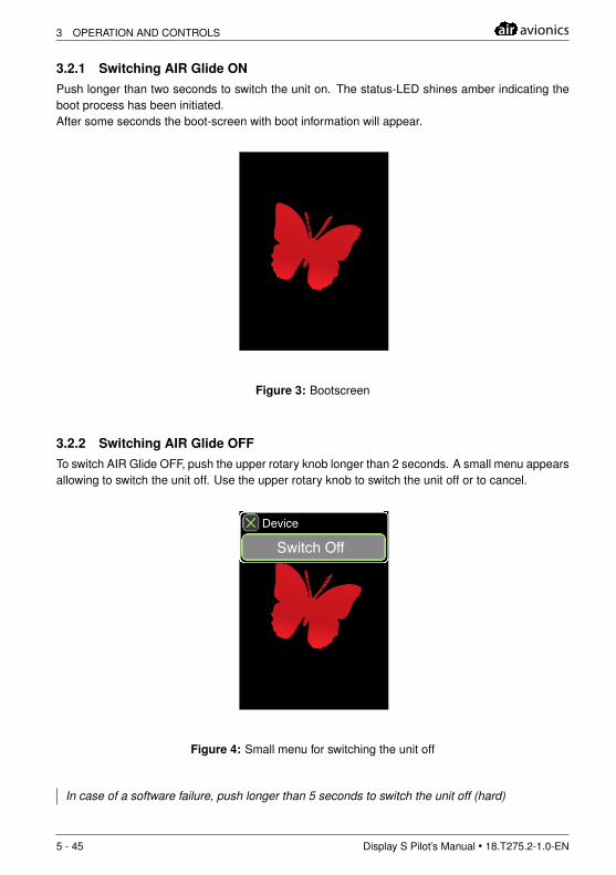
3.2.1 Switching AIR Glide ONPush longer than two seconds to switch the unit on. The status-LED shines amber indicating theboot process has been initiated.After some seconds the boot-screen with boot information will appear.
Figure 3: Bootscreen
3.2.2 Switching AIR Glide OFFTo switch AIR Glide OFF, push the upper rotary knob longer than 2 seconds. A small menu appearsallowing to switch the unit off. Use the upper rotary knob to switch the unit off or to cancel.
12.1V 8.7V
Vario AVG
Device
Switch Off
Figure 4: Small menu for switching the unit off
In case of a software failure, push longer than 5 seconds to switch the unit off (hard)
5 - 45 Display S Pilot’s Manual • 18.T275.2-1.0-EN
air avionics 3 OPERATION AND CONTROLS
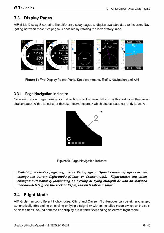
3.3 Display PagesAIR Glide Display S contains five different display pages to display available data to the user. Nav-igating between these five pages is possible by rotating the lower rotary knob.
m
12.1V 8.7V
22
1
1
0
2
23 4 5
3 4 5Vario AVG
ALT 1013.2mb
Local Time
L/D Inst.
2.11238 m
m s
14:2242
12.1V 8.7V
22
WALLDORF
1:25h120°
456m
1:25h 456m
1
10
2
23
3
ETE
NAV
ALT 1013.2mb
ETE ALT 1013.2mb
12.1V 8.7V
22
Vario AVG
ALT 1013.2mb
Local Time
L/D Inst.
2.11238 m
m s
14:2242
m
1
1
0
2
23 4 5
3 4 512.1V 8.7V 1:25h
120°456m
1:25h 456m
1
10
2
23
3
ETE
AHI
ALT 1013.2mb
ETE ALT 1013.2mb
12.1V 8.7V
1:25h 456m
1
10
2
23
3
TFCETE ALT 1013.2mb
Figure 5: Five Display Pages, Vario, Speedcommand, Traffic, Navigation and AHI
3.3.1 Page Navigation IndicatorOn every display page there is a small indicator in the lower left corner that indicates the currentdisplay page. With this indicator the user knows instantly which display page currently is active.
m
12.1V 8.7V
22
1
1
0
2
23 4 5
3 4 5Vario AVG
ALT 1013.2mb
Local Time
L/D Inst.
2.11238 m
m s
14:2242
Figure 6: Page Navigation Indicator
Switching a display page, e.g. from Vario-page to Speedcommand-page does notchange the current flight-mode (Climb- or Cruise-mode). Flight-modes are eitherchanged automatically (depending on circling or flying straight) or with an installedmode-switch (e.g. on the stick or flaps), see installation manual.
3.4 Flight-ModeAIR Glide has two different flight-modes, Climb and Cruise. Flight-modes can be either changedautomatically (depending on circling or flying straight) or with an installed mode-switch on the stickor on the flaps. Sound-scheme and display are different depending on current flight-mode.
Display S Pilot’s Manual • 18.T275.2-1.0-EN 6 - 45
3 OPERATION AND CONTROLS air avionics
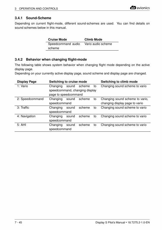
3.4.1 Sound-SchemeDepending on current flight-mode, different sound-schemes are used. You can find details onsound schemes below in this manual.
Cruise Mode Climb ModeSpeedcommand audioscheme
Vario audio scheme
3.4.2 Behavior when changing flight-modeThe following table shows system behavior when changing flight mode depending on the activedisplay page.Depending on your currently active display page, sound scheme and display page are changed.
Display Page Switching to cruise mode Switching to climb mode1: Vario Changing sound scheme to
speedcommand, changing displaypage to speedcommand
Changing sound scheme to vario
2: Speedcommand Changing sound scheme tospeedcommand
Changing sound scheme to vario,changing display page to vario
3: Traffic Changing sound scheme tospeedcommand
Changing sound scheme to vario
4: Navigation Changing sound scheme tospeedcommand
Changing sound scheme to vario
5: AHI Changing sound scheme tospeedcommand
Changing sound scheme to vario
7 - 45 Display S Pilot’s Manual • 18.T275.2-1.0-EN
air avionics 3 OPERATION AND CONTROLS
3.5 Menu-SystemAll menus work the same way and follow a hierarchic structure.
m
Menu
FlightNearestDirect To
RouteStatistics
InfosSetup
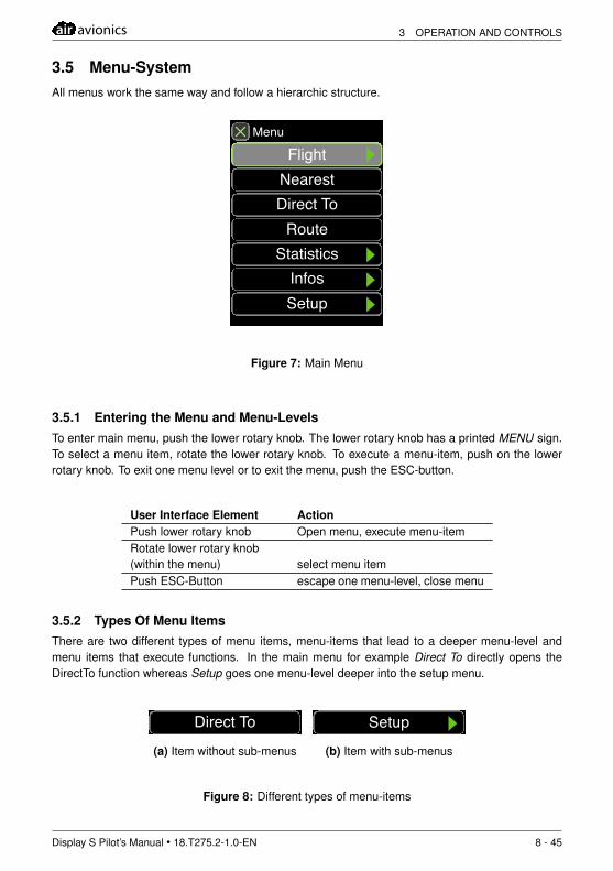
Figure 7: Main Menu
3.5.1 Entering the Menu and Menu-LevelsTo enter main menu, push the lower rotary knob. The lower rotary knob has a printed MENU sign.To select a menu item, rotate the lower rotary knob. To execute a menu-item, push on the lowerrotary knob. To exit one menu level or to exit the menu, push the ESC-button.
User Interface Element ActionPush lower rotary knob Open menu, execute menu-itemRotate lower rotary knob(within the menu) select menu itemPush ESC-Button escape one menu-level, close menu
3.5.2 Types Of Menu ItemsThere are two different types of menu items, menu-items that lead to a deeper menu-level andmenu items that execute functions. In the main menu for example Direct To directly opens theDirectTo function whereas Setup goes one menu-level deeper into the setup menu.
m
Menu
FlightNearestDirect ToStatistics
InfosSetup
(a) Item without sub-menus
m
Menu
FlightNearestDirect ToStatistics
InfosSetup
(b) Item with sub-menus
Figure 8: Different types of menu-items
Display S Pilot’s Manual • 18.T275.2-1.0-EN 8 - 45
3 OPERATION AND CONTROLS air avionics
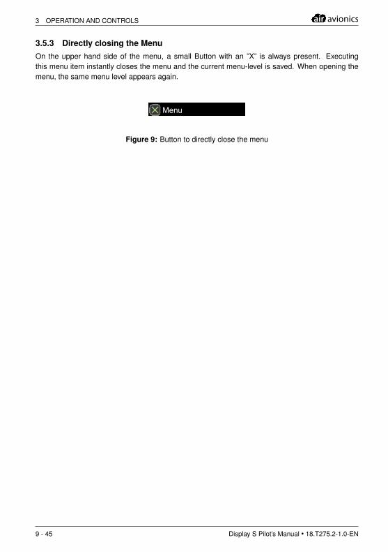
3.5.3 Directly closing the MenuOn the upper hand side of the menu, a small Button with an ”X” is always present. Executingthis menu item instantly closes the menu and the current menu-level is saved. When opening themenu, the same menu level appears again.
m
Menu
FlightNearestDirect ToStatistics
InfosSetup
Figure 9: Button to directly close the menu
9 - 45 Display S Pilot’s Manual • 18.T275.2-1.0-EN
air avionics 3 OPERATION AND CONTROLS
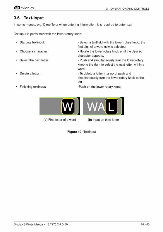
3.6 Text-InputIn some menus, e.g. DirectTo or when entering information, it is required to enter text.
Textinput is performed with the lower rotary knob:
• Starting Textinput: - Select a textfield with the lower rotary knob, thefirst digit of a word now is selected.
• Choose a character: - Rotate the lower rotary knob until the desiredcharacter appears.
• Select the next letter: - Push and simultaneously turn the lower rotaryknob to the right to select the next letter within aword.
• Delete a letter: - To delete a letter in a word, push andsimultaneously turn the lower rotary knob to theleft.
• Finishing textinput: -Push on the lower rotary knob.
m
Direct To
Walldorf
Filter W
Walldorf-MeiningenWalsrode-Luisenhe..WangeroogeWarburgWaren/VielistWarngauWasentegernbachWasserkuppe
WP
Filter-Text
(a) First letter of a word
m
Direct To
Walldorf
Filter WA L
Walldorf-MeiningenWalsrode-Luisenhe..WangeroogeWarburgWaren/VielistWarngauWasentegernbachWasserkuppe
WP
Filter-Text
(b) Input on third letter
Figure 10: Textinput
Display S Pilot’s Manual • 18.T275.2-1.0-EN 10 - 45
4 MAIN FUNCTIONS air avionics
4 Main Functions
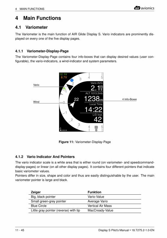
4.1 VariometerThe Variometer is the main function of AIR Glide Display S. Vario indicators are prominently dis-played on every one of the five display pages.
4.1.1 Variometer-Display-PageThe Variometer-Display-Page contains four info-boxes that can display desired values (user con-figurable), the vario-indicators, a wind-indicator and system parameters.
m
12.1V 8.7V
22
1
1
0
2
23 4 5
3 4 5Vario AVG
ALT 1013.2mb
Local Time
L/D Inst.
2.11238 m
m s
14:2242
m m s s
Wind
Vario
4 Info-Boxes
Figure 11: Variometer-Display-Page
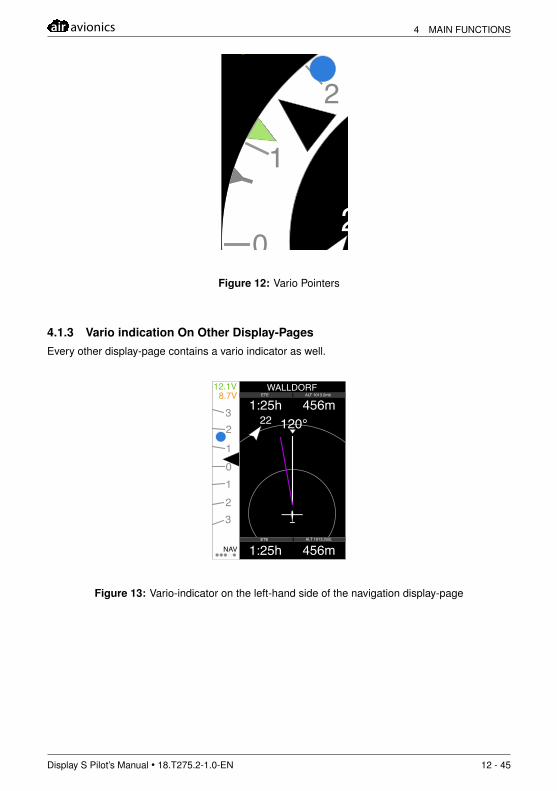
4.1.2 Vario Indicator And PointersThe vario indicator scale is a white area that is either round (on variometer- and speedcommand-display-pages) or linear (on all other display pages). It contains four different pointers that indicatebasic variometer values.Pointers differ in size, shape and color and thus are easily distinguishable by the user. The mainvariometer pointer is large and black.
Zeiger FunktionBig, black pointer Vario-ValueSmall green-grey pointer Average VarioBlue Circle Vertical Air MassLittle gray pointer (reverse) with tip MacCready-Value
11 - 45 Display S Pilot’s Manual • 18.T275.2-1.0-EN
air avionics 4 MAIN FUNCTIONS
m
12.1V 8.7V
22
1
1
0
2
23 4 5
3 4 5Vario AVG
ALT 1013.2mb
Local Time
L/D Inst.
2.11238 m
m s
14:2242
Figure 12: Vario Pointers
4.1.3 Vario indication On Other Display-PagesEvery other display-page contains a vario indicator as well.
12.1V 8.7V
22
WALLDORF
1:25h120°
456m
1:25h 456m
1
m
10
2
23
3
ETE
NAV
ALT 1013.2mb
ETE ALT 1013.2mb
Figure 13: Vario-indicator on the left-hand side of the navigation display-page
Display S Pilot’s Manual • 18.T275.2-1.0-EN 12 - 45
4 MAIN FUNCTIONS air avionics
4.2 Speedcommand
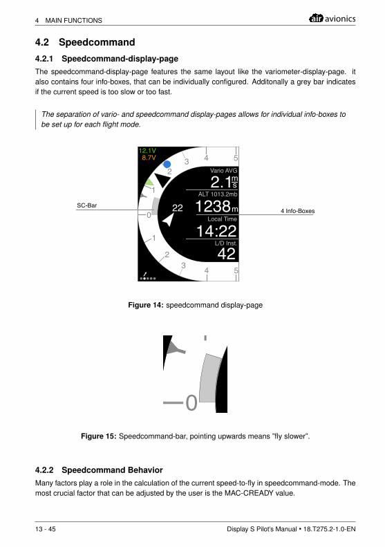
4.2.1 Speedcommand-display-pageThe speedcommand-display-page features the same layout like the variometer-display-page. italso contains four info-boxes, that can be individually configured. Additonally a grey bar indicatesif the current speed is too slow or too fast.
The separation of vario- and speedcommand display-pages allows for individual info-boxes tobe set up for each flight mode.
12.1V 8.7V
22
1
1
0
2
23 4 5
3 4 5Vario AVG
ALT 1013.2mb
Local Time
L/D Inst.
2.11238 m
m s
14:2242
m
SC-Bar4 Info-Boxes
Figure 14: speedcommand display-page
12.1V 8.7V
22
1
1
0
2
23 4 5
3 4 5Vario AVG
ALT 1013.2mb
Local Time
L/D Inst.
2.11238 m
m s
14:2242
m
Figure 15: Speedcommand-bar, pointing upwards means ”fly slower”.
4.2.2 Speedcommand BehaviorMany factors play a role in the calculation of the current speed-to-fly in speedcommand-mode. Themost crucial factor that can be adjusted by the user is the MAC-CREADY value.
13 - 45 Display S Pilot’s Manual • 18.T275.2-1.0-EN
air avionics 4 MAIN FUNCTIONS
To enter/change a MAC-CREADY value faster than entering the menu, push and simultane-ously turn the lower rotary knob.
More flight parameters relevant to speedcommand calculations can be set up in Menu, Flight.Speedcommand behavior like filters and input values can be set up in the menu under Setup,Compensation. More information in the chapter Setup of this manual.
More about speedcommand calculations and influence of different settings can be found in thechapter Calculations And Informations of this manual.
4.3 Traffic
4.3.1 Traffic-Display-Page
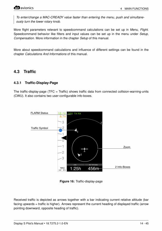
The traffic-display-page (TFC = Traffic) shows traffic data from connected collision-warning-units(CWU). It also contains two user-configurable info-boxes.
12.1V 8.7V
1:25h 456m
1
m
10
2
23
3
TFCETE ALT 1013.2mb
2
GPS TX RX
1
Traffic Symbol
Zoom
2 Info-Boxes
FLARM Status
Figure 16: Traffic-display-page
Received traffic is depicted as arrows together with a bar indicating current relative altitude (barfacing upwards = traffic is higher). Arrows represent the current heading of displayed traffic (arrowpointing downward, opposite heading of traffic).
Display S Pilot’s Manual • 18.T275.2-1.0-EN 14 - 45
4 MAIN FUNCTIONS air avionics
12.1V 8.7V
1:25h 456m
1
m
10
2
23
3
TFCETE ALT 1013.2mb
2
GPS TX RX
1
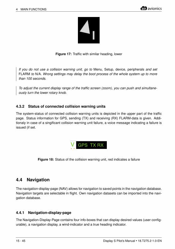
Figure 17: Traffic with similar heading, lower
If you do not use a collision warning unit, go to Menu, Setup, device, peripherals and setFLARM to N/A. Wrong settings may delay the boot process of the whole system up to morethan 100 seconds.
To adjust the current display range of the traffic screen (zoom), you can push and simultane-ously turn the lower rotary knob.
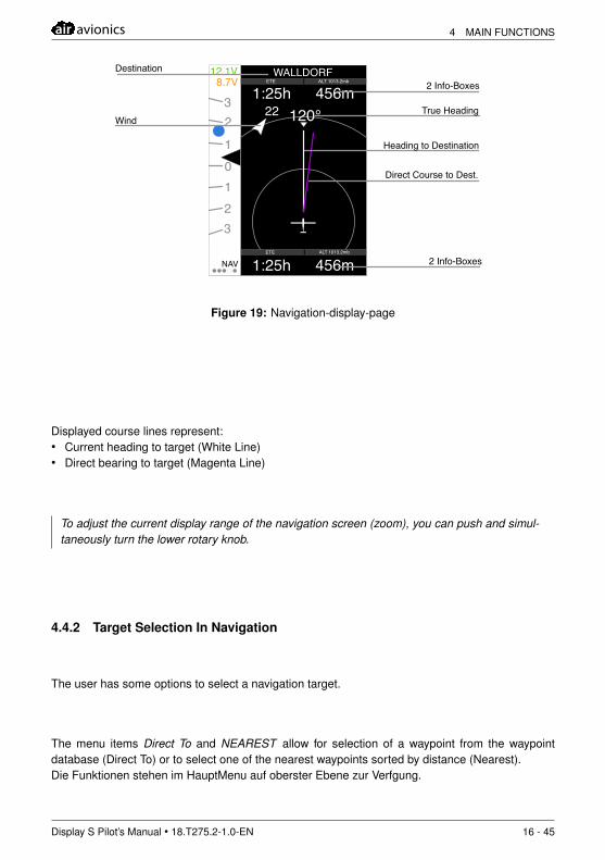
4.3.2 Status of connected collision warning units
The system-status of connected collision warning units is depicted in the upper part of the trafficpage. Status information for GPS, sending (TX) and receiving (RX) FLARM-data is given. Addi-tionaly in case of a singificant collision warning unit failure, a voice message indicating a failure isissued (if set.
12.1V 8.7V
1:25h 456m
1
m
10
2
23
3
TFCETE ALT 1013.2mb
2
GPS TX RX
1
Figure 18: Status of the collision warning unit, red indicates a failure
4.4 Navigation
The navigation-display-page (NAV) allows for navigation to saved points in the navigation database.Navigation targets are selectable in flight. Own navigation datasets can be imported into the navi-gation database.
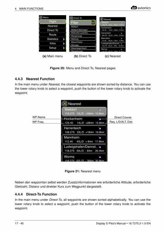
4.4.1 Navigation-display-page
The Navigation-Display-Page contains four info-boxes that can display desired values (user config-urable), a navigation display, a wind-indicator and a true heading indicator.
15 - 45 Display S Pilot’s Manual • 18.T275.2-1.0-EN
air avionics 4 MAIN FUNCTIONS
12.1V 8.7V
22
WALLDORF
1:25h120°
456m
1:25h 456m
1
m
10
2
23
3
ETE
NAV
ALT 1013.2mb
ETE ALT 1013.2mb
Wind
Destination
2 Info-Boxes
2 Info-Boxes
True Heading
Heading to Destination
Direct Course to Dest.
Figure 19: Navigation-display-page
Displayed course lines represent:• Current heading to target (White Line)• Direct bearing to target (Magenta Line)
To adjust the current display range of the navigation screen (zoom), you can push and simul-taneously turn the lower rotary knob.
4.4.2 Target Selection In Navigation
The user has some options to select a navigation target.
The menu items Direct To and NEAREST allow for selection of a waypoint from the waypointdatabase (Direct To) or to select one of the nearest waypoints sorted by distance (Nearest).Die Funktionen stehen im HauptMenu auf oberster Ebene zur Verfgung.
Display S Pilot’s Manual • 18.T275.2-1.0-EN 16 - 45
4 MAIN FUNCTIONS air avionics
m
Menu
FlightNearestDirect To
RouteStatistics
InfosSetup
(a) Main menu
m
Direct To
Walldorf
Filter W
Walldorf-MeiningenWalsrode-Luisenhe..WangeroogeWarburgWaren/VielistWarngauWasentegernbachWasserkuppe
WP
Filter-Text
(b) Direct To
m
Nearest
Hockenheim123.40 14L/D +284m 15.8km
Herrenteich108.275 33L/D +184m 16.8km
Mannheim112.40 40L/D + 84m 17.8km
Ludwigshafen/Dannst..118.275 50L/D - 84m 20.4km
Worms118.275 62L/D - 384m 30.8km
Walldorf118.275 10L/D +384m 10.8km
(c) Nearest
Figure 20: Menu and Direct-To, Nearest pages
4.4.3 Nearest FunctionIn the main menu under Nearest, the closest waypoints are shown sorted by distance. You can usethe lower rotary knob to select a waypoint, push the button of the lower rotary knob to activate thewaypoint.
m
Nearest
Hockenheim123.40 14L/D +284m 15.8km
Herrenteich108.275 33L/D +184m 16.8km
Mannheim112.40 40L/D + 84m 17.8km
Ludwigshafen/Dannst..118.275 50L/D - 84m 20.4km
Worms118.275 62L/D - 384m 30.8km
Walldorf118.275 10L/D +384m 10.8km
WP Freq.WP-Name Direct Course
Req. L/D/ALT, Dist.
Figure 21: Nearest menu
Neben den waypointsn selbst werden Zusatzinformationen wie erforderliche Altitude, erforderlicheGleitzahl, Distanz und direkter Kurs zum Wegpunkt dargestellt.
4.4.4 Direct-To FunctionIn the main menu under Direct-To, all waypoints are shown sorted alphabetically. You can use thelower rotary knob to select a waypoint, push the button of the lower rotary knob to activate thewaypoint.
17 - 45 Display S Pilot’s Manual • 18.T275.2-1.0-EN
air avionics 4 MAIN FUNCTIONS
It is possible to enter a waypoint name (or the first letters) via text input. More on text input can befound in the section Oparation and Controls of this manual.
m
Direct To
Walldorf
Filter W
Walldorf-MeiningenWalsrode-Luisenhe..WangeroogeWarburgWaren/VielistWarngauWasentegernbachWasserkuppe
WP
Filter-Text
Figure 22: DirectTo menu
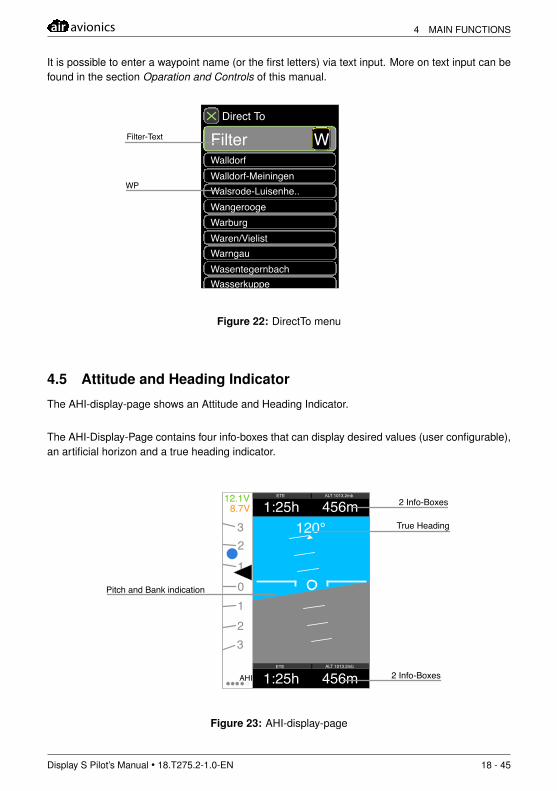
4.5 Attitude and Heading Indicator
The AHI-display-page shows an Attitude and Heading Indicator.
The AHI-Display-Page contains four info-boxes that can display desired values (user configurable),an artificial horizon and a true heading indicator.
12.1V 8.7V 1:25h
120°456m
1:25h 456m
1
m
10
2
23
3
ETE
AHI
ALT 1013.2mb
ETE ALT 1013.2mb
2 Info-Boxes
2 Info-Boxes
Pitch and Bank indication
True Heading
Figure 23: AHI-display-page
Display S Pilot’s Manual • 18.T275.2-1.0-EN 18 - 45
4 MAIN FUNCTIONS air avionics
This function is not allowed in some competitions. Display of attitude information can be lockedin competitions, please refer to the AHI-Lock-section of this manual for details.
Displayed data is not certified. Never rely on AIR Glide while flying in clouds. Neverintentionally enter clouds while flying with AIR Glide!
No cloud flying is permitted except if permitted by law with current training a licensefor cloud-flying and certified equipment.
19 - 45 Display S Pilot’s Manual • 18.T275.2-1.0-EN
air avionics 4 MAIN FUNCTIONS
4.6 Flight Logging
The AIR Glide Sensor Unit (ISU) contains an integrated IGC approved flight recorder. The flightrecorder records files in IGC format. The flight recorder is names ”Altair Recorder Unit V3” andintegrated into the Sensor Unit (ISU). The Flight recorder is configured vie AIR Glide Displays likethe Display S.
Never try to open the enclosure of AIR Glide Sensor Unit (ISU). Any attempt to openthe enclosure or loosen enclosre screws result void the integrated seals past recovery.Recorded flights loose validity.
Interruptions of recording of more than 5 minutes (e.g. in case of power loss) result in therecording of two flights with two separate IGC-Files.
4.6.1 Entering and declaring IGC Flight-Info and Tasks
Tasks as well as IGC-Flight-Info, i.e. information about the aircraft, pilot etc. can be entered in themenu. Go to menu, flight to enter data.
• Entering a Route: - Go to Menu, Route- Enter a desired route-name into ”Name”.- Go to ”waypoints” and set up desiredwaypoints.
• Setting up a route with waypoints: - Go to ”waypoints”- Choose a desired waypoint (e.g. ”Start”) orinsert a waypoint with ”Add”- Click on the waypoint you wish to change, aCoordinate-Entry/waypoint-selection menuappears.- Enter desired coordinates or select a waypointfrom the waypoint database (similar to Direct-To).- Use the ESC-button to return to the waypointslist.
• Entering a route from a file: - Synchronize a CUP-File that contains a route inthe USB-Stick waypoints folder (see chapter”Data Synchronization” in this manual fordetails).- Go to Menu, Route-The route from the file will be available.
1• Entering a Route from an otherdevice:
- Declare a route to AIR Glide. AIR Glide acts as”Cambridge 302” in third party software. Makesure to use a datarate of 38400Bd.)
- Go to Menu, Route.
1Butterfly NMEA Interface Unit required
Display S Pilot’s Manual • 18.T275.2-1.0-EN 20 - 45
4 MAIN FUNCTIONS air avionics
The declared route from the device will beavailable.
4.6.2 Entering IGC Flight-Info
• - Go to Menu, Route, IGC.• Enter your Data.• Declare to a desired Flight Recorder (e.g. AIR Glide Sensor Unit (ISU)/RU).
4.6.3 Declaring a Route/Flight-info
• - Go to Menu, Route, Declare.• Select a desired flight recorder, e.g. ”ISU/RU”
ISU/RU describes the flight recorder that is integrated in the AIR Glide Sensor Unit (ISU). AIRGlide is also capable of declaring to other flight recorders, e.g a connected FLARM IGC
4.6.4 Downloading Flights
Downloading is only possible after at least 5 minutes the device operates after landing.
Recorded flights can be downloaded with a USB stick. When booting AIR Glide Display S with aninserted USB-stick a menu appears that allows for downloading all flights that are not present onthe USB-Stick. All Flights are put into the folder ”Flights” on the USB-Stick.
• Preparation: - Insert a USB-Stick into one of the USB-Ports ofthe display-unit (with or without extension).- Boot the device (if already running restart.
• Downloading Flights: - During the boot process, a message indicating”new flights found” appears.- Click on ”Download” with the upper rotary knobto download flights.- Wait until download is finished. This may takeup to some minutes depending on number andlength of flights not on the USB-Stick.
21 - 45 Display S Pilot’s Manual • 18.T275.2-1.0-EN
air avionics 4 MAIN FUNCTIONS
12.1V 8.7V
Vario AVG
Found new Flights
Download
Cancel
Figure 24: Downloading Flights
With the use of special software, downloading IGC-files is possible via RS232 directly on the AIRGlide Sensor Unit (ISU).
4.6.5 Flight Recorder Setup
The Flight-Recorder log-interval may be set up in Menu, Setup, Flightrec.
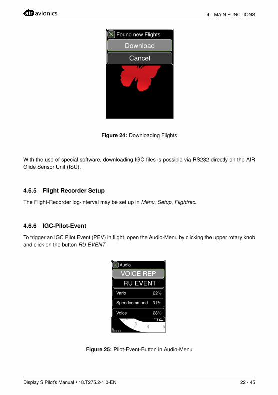
4.6.6 IGC-Pilot-Event
To trigger an IGC Pilot Event (PEV) in flight, open the Audio-Menu by clicking the upper rotary knoband click on the button RU EVENT.
12.1V 8.7V
22
1
1
0
2
23 4 5
3 4 5Vario AVG
ALT 1013.2mb
Local Time
L/D Inst.
2.11238 m
m
14:2242
m
Audio
Vario 22%
Speedcommand 31%
Voice 28%
VOICE REPRU EVENT
Figure 25: Pilot-Event-Button in Audio-Menu
Display S Pilot’s Manual • 18.T275.2-1.0-EN 22 - 45
4 MAIN FUNCTIONS air avionics
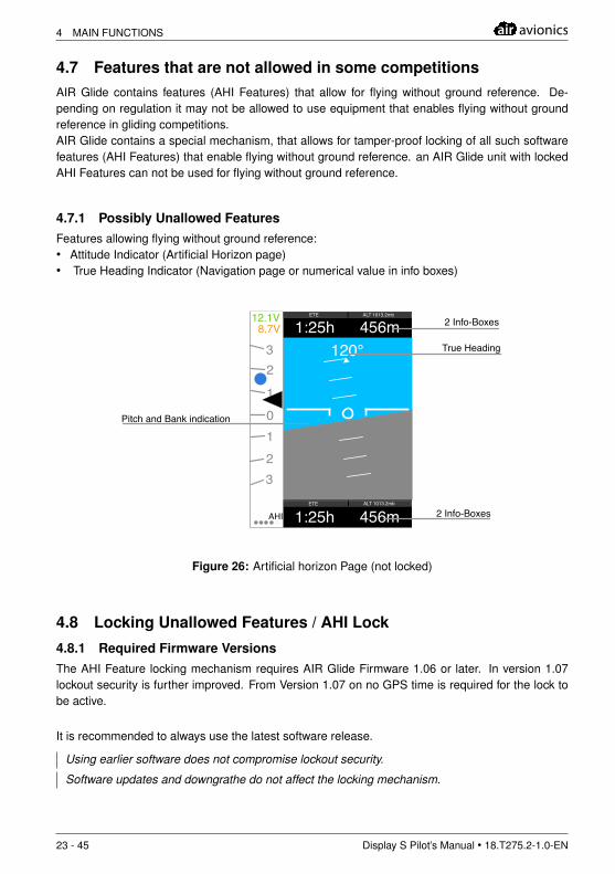
4.7 Features that are not allowed in some competitionsAIR Glide contains features (AHI Features) that allow for flying without ground reference. De-pending on regulation it may not be allowed to use equipment that enables flying without groundreference in gliding competitions.AIR Glide contains a special mechanism, that allows for tamper-proof locking of all such softwarefeatures (AHI Features) that enable flying without ground reference. an AIR Glide unit with lockedAHI Features can not be used for flying without ground reference.
4.7.1 Possibly Unallowed FeaturesFeatures allowing flying without ground reference:• Attitude Indicator (Artificial Horizon page)• True Heading Indicator (Navigation page or numerical value in info boxes)
12.1V 8.7V 1:25h
120°456m
1:25h 456m
1
m
10
2
23
3
ETE
AHI
ALT 1013.2mb
ETE ALT 1013.2mb
2 Info-Boxes
2 Info-Boxes
Pitch and Bank indication
True Heading
Figure 26: Artificial horizon Page (not locked)
4.8 Locking Unallowed Features / AHI Lock
4.8.1 Required Firmware VersionsThe AHI Feature locking mechanism requires AIR Glide Firmware 1.06 or later. In version 1.07lockout security is further improved. From Version 1.07 on no GPS time is required for the lock tobe active.
It is recommended to always use the latest software release.
Using earlier software does not compromise lockout security.
Software updates and downgrathe do not affect the locking mechanism.
23 - 45 Display S Pilot’s Manual • 18.T275.2-1.0-EN
air avionics 4 MAIN FUNCTIONS
4.8.2 Security
The lockout mechanism is applied to all units in an AIR Glide installation. AHI Locking can not becircumvent by interchanging single components of an AIR Glide installation.
The lockout mechanism amongst others is stored in the secure part of the AIR Glide Sensor Unit(ISU) which is a secure fully IGC certified flight recorder with tamper proof enclosure and tamperproof encrypted software.
4.8.3 Locking the AHI
In order to use the AHI Lockout function, go to Menu then Setup then Flightrecorder and here toAHRS Lock. Click on Lock to activate the lock. To deactivate the lock, click on Unlock
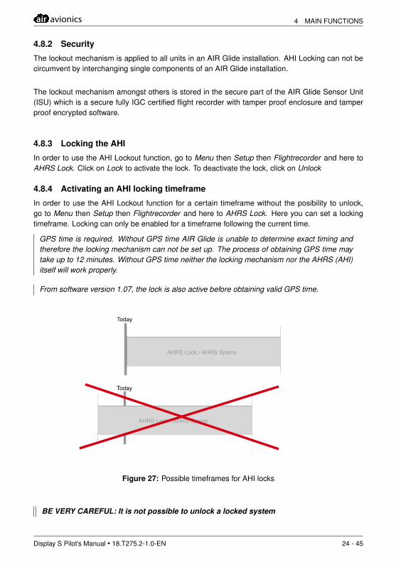
4.8.4 Activating an AHI locking timeframe
In order to use the AHI Lockout function for a certain timeframe without the posibility to unlock,go to Menu then Setup then Flightrecorder and here to AHRS Lock. Here you can set a lockingtimeframe. Locking can only be enabled for a timeframe following the current time.
GPS time is required. Without GPS time AIR Glide is unable to determine exact timing andtherefore the locking mechanism can not be set up. The process of obtaining GPS time maytake up to 12 minutes. Without GPS time neither the locking mechanism nor the AHRS (AHI)itself will work properly.
From software version 1.07, the lock is also active before obtaining valid GPS time.
Today
AHRS Lock / AHRS Sperre
Today
AHRS Lock / AHRS Sperre
Figure 27: Possible timeframes for AHI locks
BE VERY CAREFUL: It is not possible to unlock a locked system
Display S Pilot’s Manual • 18.T275.2-1.0-EN 24 - 45
4 MAIN FUNCTIONS air avionics
4.8.5 Behavior when AHI lock is active
When AHI lock is active, all features allowing flying without ground reference are locked and cannot be displayed. For displayed heading data, a 5Hz GPS signal is used.
4.8.6 Determining if lock is active
During the timeframe the AHI-lock is enabled the user or e.g. a competition staff can at any timereview the set up locking interval and thus is able to judge if the AHI lock has been enabled for thecorrect time in a competition.
To review AHI lock status go to Menu then Setup then Flightrecorder and here to AHRS Lock
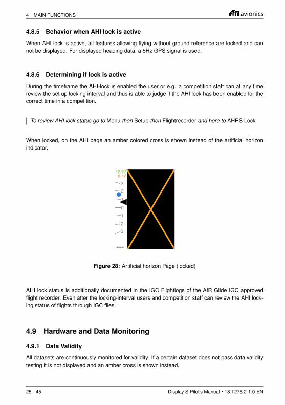
When locked, on the AHI page an amber colored cross is shown instead of the artificial horizonindicator.
12.1V 8.7V
1
m
10
2
23
3
Figure 28: Artificial horizon Page (locked)
AHI lock status is additionally documented in the IGC Flightlogs of the AIR Glide IGC approvedflight recorder. Even after the locking-interval users and competition staff can review the AHI lock-ing status of flights through IGC files.
4.9 Hardware and Data Monitoring
4.9.1 Data Validity
All datasets are continuously monitored for validity. If a certain dataset does not pass data validitytesting it is not displayed and an amber cross is shown instead.
25 - 45 Display S Pilot’s Manual • 18.T275.2-1.0-EN
air avionics 4 MAIN FUNCTIONS
m
12.1V 8.7V
22
1
1
0
2
23 4 5
3 4 5Airspeed (IAS)
ALT 1013.2mb
Local Time
L/D Inst.
1238 m
14:2242
m m s s
Wind
Vario
4 Info-Boxes
Figure 29: Invalid dataset in an info-box
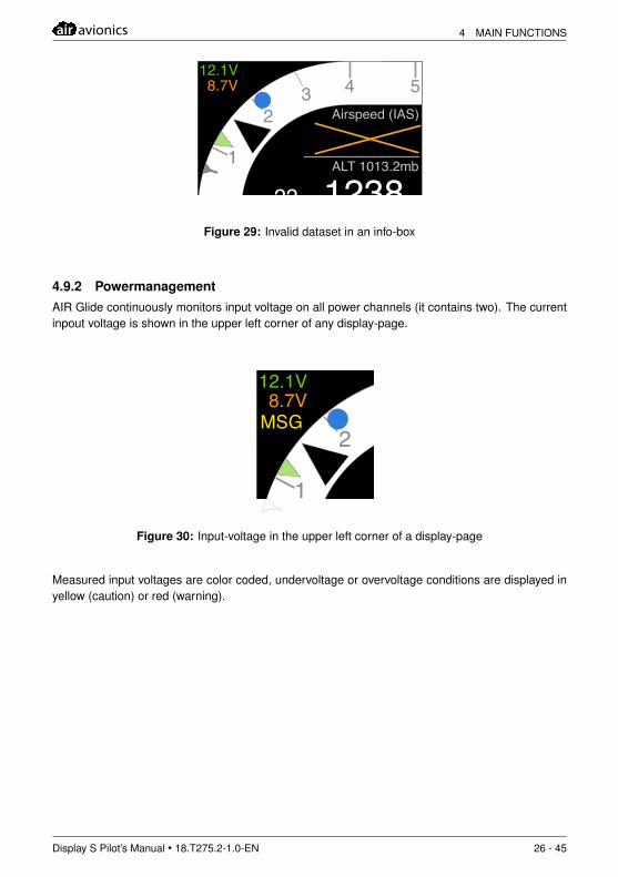
4.9.2 PowermanagementAIR Glide continuously monitors input voltage on all power channels (it contains two). The currentinpout voltage is shown in the upper left corner of any display-page.
12.1V 8.7V
MSG
22
1
1
0
2
23 4 5
3 4 5Vario AVG
ALT 1013.2mb
Local Time
L/D Inst.
2.11238 m
m s
14:2242
m
Figure 30: Input-voltage in the upper left corner of a display-page
Measured input voltages are color coded, undervoltage or overvoltage conditions are displayed inyellow (caution) or red (warning).
Display S Pilot’s Manual • 18.T275.2-1.0-EN 26 - 45
5 AUDIO-SYSTEM air avionics
5 Audio-System
The Audiosystem consists of a voice-engine and a vario-audio generator.
AIR Glide does not deliver equal sound quality over the entire volume range. Starting at about2/3 of the maximum volume, audio-output is overdriven to achieve more volume. From thenon distortion factor increases and audio-quality decreases (maximum output 1.5W at 8 Ohm,distortion factor below 1 percent).
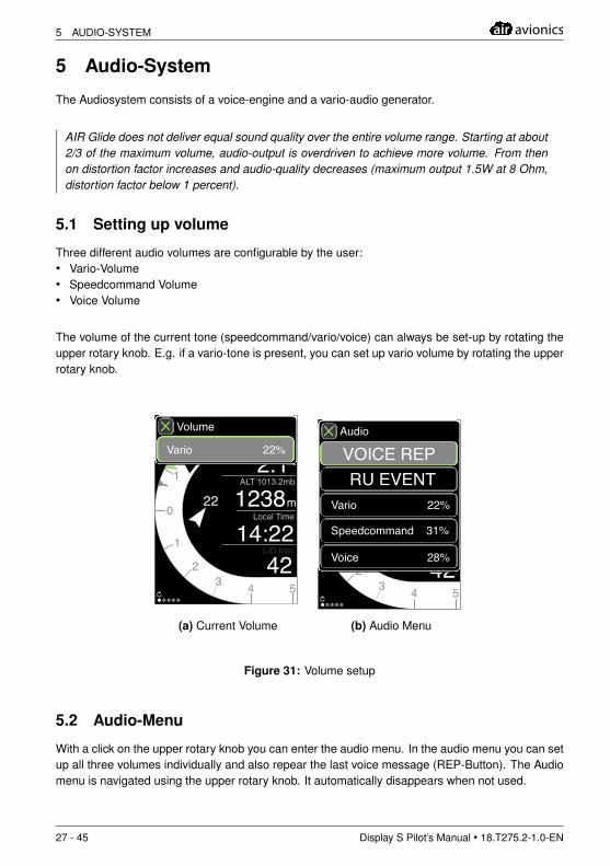
5.1 Setting up volume
Three different audio volumes are configurable by the user:• Vario-Volume• Speedcommand Volume• Voice Volume
The volume of the current tone (speedcommand/vario/voice) can always be set-up by rotating theupper rotary knob. E.g. if a vario-tone is present, you can set up vario volume by rotating the upperrotary knob.
12.1V 8.7V
22
1
1
0
2
23 4 5
3 4 5Vario AVG
ALT 1013.2mb
Local Time
L/D Inst.
2.11238 m
m
14:2242
m
Volume
Vario 22%
(a) Current Volume
12.1V 8.7V
22
1
1
0
2
23 4 5
3 4 5Vario AVG
ALT 1013.2mb
Local Time
L/D Inst.
2.11238 m
m
14:2242
m
Audio
Vario 22%
Speedcommand 31%
Voice 28%
VOICE REPRU EVENT
(b) Audio Menu
Figure 31: Volume setup
5.2 Audio-Menu
With a click on the upper rotary knob you can enter the audio menu. In the audio menu you can setup all three volumes individually and also repear the last voice message (REP-Button). The Audiomenu is navigated using the upper rotary knob. It automatically disappears when not used.
27 - 45 Display S Pilot’s Manual • 18.T275.2-1.0-EN
air avionics 5 AUDIO-SYSTEM
5.3 Bass Boost FeatureAIR Glide features a function that allows to increase volume of lower frequencies automatically.This ”Bass Boost” feature allows the use of small speakers that naturally have no good perfor-mance at low frequencies.
To set up you Bass Boost, go to Menu, Setup und Device and setBass-Boost to a desired value.The standard setting for the supplied speaker is 3, the value can be set from 0 to 9.
5.4 Vario/speedcommand AudioVario and speedcommand audio schemes are provided to give aural feedback on current vehicledynamics in all flight-mode. Pilot gets feedback without having to look inside the cockpit.
Never disrespect aircraft restrictions in speed and acceleration, even if the speedcom-mand function tells you to do so.
5.4.1 Sound-Scheme in Cruise-Mode
Status sound-pitch BeepsFaster decreases, when aircraft shall ac-
celerateDouble-Beep of constant duration
Slower Increases, when aircraft shall decel-erate
short Double-Beep
It is possible to activate a climb-mode-sound-scheme even if in cruise-mode under certain condi-tions. Go to Menu, Setup and Device and set SC vario-sounds to a desired condition. The followingtable describes possible settings.
Status sound-pitch BeepsSpeed-to-fly slower than speed ofminimum sink
Increases whenclimbing more
short beep, faster whenclimbing more
Vario-Value better than half of thecurrent MC-Value
Increases whenclimbing more
short beep, faster whenclimbing more
If SC-Vario-Sounds are inactive, a positive relative netto value leads to additional modulationindicating a thermals lift before starting to circle / switch modes
5.4.2 Sound-Scheme in Climb-Mode
Status sound-pitch BeepsClimbing Increases when climbing more short Beep, faster when climbing
moreSinking decreases when sinking more constant tone
Display S Pilot’s Manual • 18.T275.2-1.0-EN 28 - 45
5 AUDIO-SYSTEM air avionics
5.5 Voice OutputAIR Glide creates voice messages for traffic- or obstacle-warnings, warnings regarding configu-ration (gear/flap warnings), warnings when flying outside the safe flight envelope and also statusmessages regarding connected devices (e.g. FLARM) or system messages (GPS, battery etc.).
The voice-system is interactive, the user is able to acknowledge voice-messages and to repeatthem if desired. All voice messages can be deactivated and are configurable in Menu, Setup,Voice.
5.5.1 Message PrioritiesFour different message priorities are used to filter and schedule voice messages.
Format Sound ImportanceMessage no InformalNote Ping lowCaution BeepBeep ImportantWarning Siren urgent!
5.5.2 MessagesThe following messages are currently implemented.
In Traffic-messages relative altitude is expressed as below, lower, higher, above. Distance isindicated in 100m steps, e.g. an object with 500m distance has the number five.
Message Reason Format ExampleInfomessagetraffic
traffic information Ping, direction,altitude,traffic-type, distance
”PING 12 O’Clock aboveGlider 5”
cautionmessagetraffic
dangerous traffic BeepBeep, direc-tion,altitude, traffic-type,distance
”BeepBeep 12 O’Clockabove Glider 5”
Warnmessagetraffic
Very dangeroustraffic
Siren, direction,altitude,traffic-type, distance
”Siren 12 O’Clock aboveGlider 5”
cautionmessageobstacle
obstacle collisionhazard
BeepBeep, Obstacle,Distance
”Siren, Obstacle, five”
Warnmessageobstacle
major obstacle col-lision hazard
Siren,Obstacle, Distanz ”Siren, Obstacle, five”
WarnmessageVNE
Exceeding VNE Siren,Speed ”BeepBeep Speed”
InfomessageVA
Faster than VA BeepBeep,Speed ”BeepBeep Speed”
message air-brakes
airbrakes notlocked duringtakeoff
BeepBeep,Airbrakes ”BeepBeep Airbrakes”
29 - 45 Display S Pilot’s Manual • 18.T275.2-1.0-EN
air avionics 5 AUDIO-SYSTEM
message gear airbrakes notlocked, gear re-tracted
BeepBeep,Gear ”BeepBeep Gear”
5.5.3 Acknowledging MessagesMessages may be acknowledged by clicking on the ACK-Buttton. Acknowledged messages arenot repeated for a certain timeframe. The timeframe depends on message priority.
• message priority increases: Acknowledged messages are repeated with updated informationon values like e.g. distance. • message priority decreases: Acknowledges messages are notrepeated.
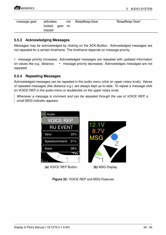
5.5.4 Repeating MessagesAcknowledged messages can be repeated in the audio menu (click on upper rotary knob). Valuesof repeated messages (like distance e.g.) are always kept up-to-date. To repeat a message clickon VOICE REP in the audio-menu or doubleclick on the upper rotary knob.
Whenever a message is imminent and can be repeated through the use of VOICE REP, asmall MSG indicator appears.
12.1V 8.7V
22
1
1
0
2
23 4 5
3 4 5Vario AVG
ALT 1013.2mb
Local Time
L/D Inst.
2.11238 m
m
14:2242
m
Audio
Vario 22%
Speedcommand 31%
Voice 28%
VOICE REPRU EVENT
(a) VOICE REP Button
12.1V 8.7V
MSG
22
1
1
0
2
23 4 5
3 4 5Vario AVG
ALT 1013.2mb
Local Time
L/D Inst.
2.11238 m
m s
14:2242
m
(b) MSG Display
Figure 32: VOICE REP and MSG Features
Display S Pilot’s Manual • 18.T275.2-1.0-EN 30 - 45
6 SETUP air avionics
6 Setup
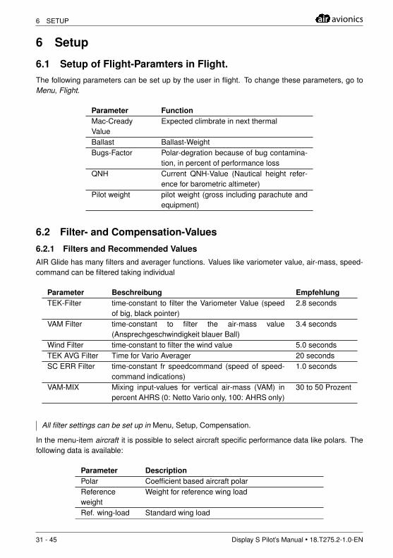
6.1 Setup of Flight-Paramters in Flight.The following parameters can be set up by the user in flight. To change these parameters, go toMenu, Flight.
Parameter FunctionMac-CreadyValue
Expected climbrate in next thermal
Ballast Ballast-WeightBugs-Factor Polar-degration because of bug contamina-
tion, in percent of performance lossQNH Current QNH-Value (Nautical height refer-
ence for barometric altimeter)Pilot weight pilot weight (gross including parachute and
equipment)
6.2 Filter- and Compensation-Values
6.2.1 Filters and Recommended ValuesAIR Glide has many filters and averager functions. Values like variometer value, air-mass, speed-command can be filtered taking individual
Parameter Beschreibung EmpfehlungTEK-Filter time-constant to filter the Variometer Value (speed
of big, black pointer)2.8 seconds
VAM Filter time-constant to filter the air-mass value(Ansprechgeschwindigkeit blauer Ball)
3.4 seconds
Wind Filter time-constant to filter the wind value 5.0 secondsTEK AVG Filter Time for Vario Averager 20 secondsSC ERR Filter time-constant fr speedcommand (speed of speed-
command indications)1.0 seconds
VAM-MIX Mixing input-values for vertical air-mass (VAM) inpercent AHRS (0: Netto Vario only, 100: AHRS only)
30 to 50 Prozent
All filter settings can be set up in Menu, Setup, Compensation.
In the menu-item aircraft it is possible to select aircraft specific performance data like polars. Thefollowing data is available:
Parameter DescriptionPolar Coefficient based aircraft polarReferenceweight
Weight for reference wing load
Ref. wing-load Standard wing load
31 - 45 Display S Pilot’s Manual • 18.T275.2-1.0-EN
air avionics 6 SETUP
payload maximum payloadEmpty weight empty weightBallast maximum ballastVNE Never exceed speedVA Maximum speed in rough air
For changes to take effect restarting the unit is required.
You can also import own aircraft-performance data. See the chapter data-synchronization ofthis manual for details.
6.3 Magnetometer-Compensation
Depending on installation quality and general aircraft specific factors there may be magnetic inter-ference disturbing the systems sensors. In order to minimize disturbance at a certain installationposition, magnetometer sensors inside the AIR Glide Sensor Unit (ISU).
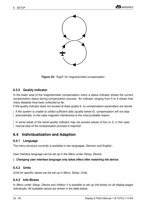
The magnetometer compensation is performed in-flight through flying of ”eights”.
In-Flight magnetometer compensation may only be performed by personal that is fa-miliar with the aircraft. It must be performed in safe altitudes and if required underguidance by ATC. Calibration does not require the pilot to look inside the aircraft, al-ways maintain a good lookout
.
The calibration process may be aborted at any time. Do not proceed with calibration if unsureof your current flight-situation, altitude or surrounding traffic.
6.3.1 Performing Magnetometer Compensation
• Go to Menu, Setup and ISU and click on Magneto Comp.• Fly ”eights” with varying bank angle. Best results are achieved when flying the eight in north-south direction. Do not switch your devices off, that normally are active in-flight.• After having collected sufficient data, the compensation process automatically stops. You canmanually stop compensation by clicking in Magneto Comp. Stop.• After compensation the Sensor Unit (ISU) is rebooted. In a time of 1 to 5 minutes this can leadto display of non-plausible values.
Display S Pilot’s Manual • 18.T275.2-1.0-EN 32 - 45
6 SETUP air avionics
Figure 33: ”Eight” for magnetometer compensation
6.3.2 Quality indicator
In the lower area of the magnetometer compensation menu a status indicator shows the currentcompensation status during compensation process. An indicator ranging from 0 to 9 shows howmany datasets have been collected so far.If the quality indicator does not exceed at least quality 6, no compensation parameters are stored.
If the system is unable to collect sufficient data (quality below 6), compensation will not stopautomatically. In this case magnetic interference is the most probable reason.
In some areas of the world quality indicator may not exceed values of four or 5, in this casemanual stop of the compensation process is required.
6.4 Individualization and Adaption
6.4.1 Language
The menu structure currently is available in two languages, German and English..
User interface language can be set up in the Menu under Setup, Device.
Changing user interface language only takes effect after restarting the device.
6.4.2 Units
Units for specific values can be set up in Menu, Setup, Units.
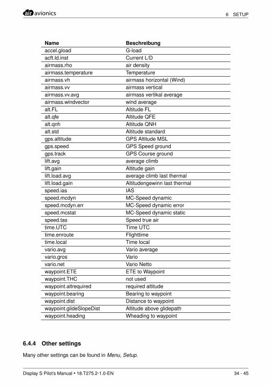
6.4.3 Info-Boxes
In Menu under Setup, Device and Infobox it is possible to set up info-boxes on all display-pagesindividually. All available values are shown in the table below.
33 - 45 Display S Pilot’s Manual • 18.T275.2-1.0-EN
air avionics 6 SETUP
Name Beschreibungaccel.gload G-loadacft.ld.inst Current L/Dairmass.rho air densityairmass.temperature Temperatureairmass.vh airmass horizontal (Wind)airmass.vv airmass verticalairmass.vv.avg airmass vertikal averageairmass.windvector wind averagealt.FL Altitude FLalt.qfe Altitude QFEalt.qnh Altitude QNHalt.std Altitude standardgps.altitude GPS Altitude MSLgps.speed GPS Speed groundgps.track GPS Course groundlift.avg average climblift.gain Altitude gainlift.load.avg average climb last thermallift.load.gain Altitudengewinn last thermalspeed.ias IASspeed.mcdyn MC-Speed dynamicspeed.mcdyn.err MC-Speed dynamic errorspeed.mcstat MC-Speed dynamic staticspeed.tas Speed true airtime.UTC Time UTCtime.enroute Flighttimetime.local Time localvario.avg Vario averagevario.gros Variovario.net Vario Nettowaypoint.ETE ETE to Waypointwaypoint.THC not usedwaypoint.altrequired required altitudewaypoint.bearing Bearing to waypointwaypoint.dist Distance to waypointwaypoint.glideSlopeDist Altitude above glidepathwaypoint.heading Wheading to waypoint
6.4.4 Other settings
Many other settings can be found in Menu, Setup.
Display S Pilot’s Manual • 18.T275.2-1.0-EN 34 - 45

6 SETUP air avionics
6.5 Factory ResetA reset of individual settings to factory settings is possible.
• Reset general settings to factorysettings (Flightrecorder andMagnetometer remain unchanged.)
Go to Menu, Setup, Device and Factory Settings
• Reset Flightrecorder settings tofactory settings
Gehen Sie auf Menu, Setup, Flightrecorder andFactory Settings
• Reset Magnetometer Compensationto factory settings
Go to Menu, Setup, ISU, Magneto Comp andFactory Settings
35 - 45 Display S Pilot’s Manual • 18.T275.2-1.0-EN
air avionics 7 MAINTENANCE AND FIRST USE
7 Maintenance and First Use
7.1 First Use
7.1.1 Switching AIR Glide on the first time
Push the button in the upper rotary knob for 3 seconds until the status-LED begins to shine. Aftera short time the Butterfly Logo appears and boot-information is shown.
If you do not have a collision warning system connected, boot-up-time will be about 100 sec-onds longer. Go to Menu, Setup, Device, Peripherals to change settings accordingly.
Depending on installation, it is normal that the artificial horizon is not level before flight.
7.2 Required Settings
7.2.1 Before first flight
Before the first flight the following settings are mandatory.
• Select an aircraft type from the list in Menu, Setup, Compensation• Adjust all time filters in the same menu.• Set the audio volume to a desired value.• Select system language according to your requirements (Details about language setup in thechapter Setup of this manual).• Go to Menu, Setup, Device, Peripherals and set all your connected peripherals. Set all not con-nected items to N/A and all others to appropriate values.
without a proper setup in the peripherals settings, some function will not work .
7.2.2 Special settings when installing multiple displays
• Make sure all peripheral settings are setup correctly in each display unit corresponding to con-nected peripherals• Go to Menu, Setup, Device and set the CANas Node ID of the secondary unit to the value ”2”.
without a proper setup a two-seater installation will not work .
7.2.3 During first flight
• Inspect heading and wind values. If you experience inaccuracies in heading or no wind display,perform a magnetometer compensation according to the chapter Magnetometer-Compensation ofthis manual
Depending on installation, in some cases a magnetometer compensation is not required.
Display S Pilot’s Manual • 18.T275.2-1.0-EN 36 - 45
7 MAINTENANCE AND FIRST USE air avionics
7.3 Softwareupdates
Firmware of all AIR Glide subsystems can be easily updated by the user using a USB-Stick.
7.3.1 Prepare an Update
Make sure your USB-Stick is FAT-Formatted.AIR Glide Firmware Files always have the name T-275-000.bin, make sure that this exactname is used and also that the file ending always is ”bin”.
• Download current firmware here: www.air-avionics.com• Put your file into a folder called ”firmware” an a USB-stick. USB-Sticks synced with AIR Glidealready have this folder created.
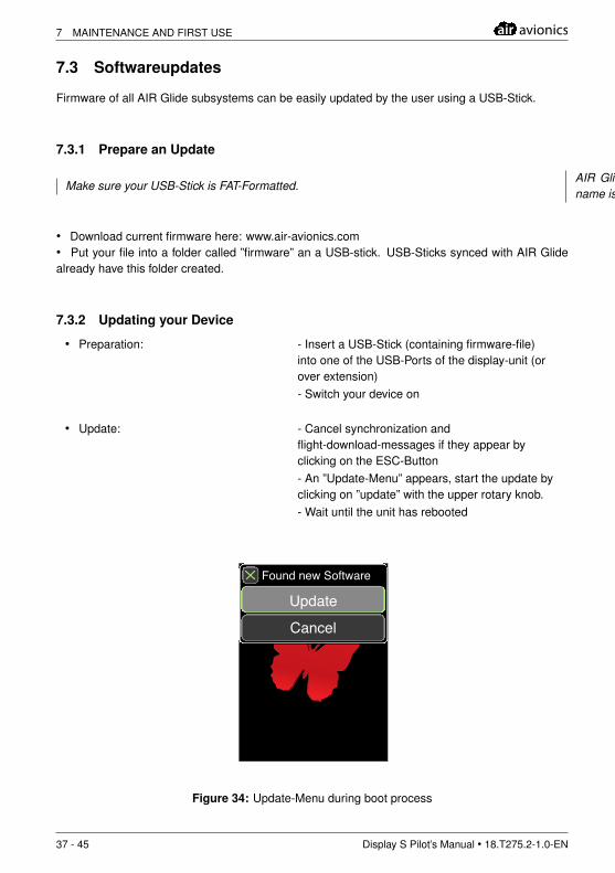
7.3.2 Updating your Device
• Preparation: - Insert a USB-Stick (containing firmware-file)into one of the USB-Ports of the display-unit (orover extension)- Switch your device on
• Update: - Cancel synchronization andflight-download-messages if they appear byclicking on the ESC-Button- An ”Update-Menu” appears, start the update byclicking on ”update” with the upper rotary knob.- Wait until the unit has rebooted
12.1V 8.7V
Vario AVG
Found new Software
Update
Cancel
Figure 34: Update-Menu during boot process
37 - 45 Display S Pilot’s Manual • 18.T275.2-1.0-EN
air avionics 7 MAINTENANCE AND FIRST USE
Make sure that AIR Glide always has power during the update process. Switching theunit off during update may cause damage beyond easy repair.
7.4 Data SynchronizationMany different datasets can be synced between AIR Glide and a USB-Stick. All data between AIRGlide and the USB-Stick are kept in sync during synchronization.
7.4.1 Behavior• During the first synchronization (with an empty USB-Stick) the normal folder structure is created.
• Datasets that are not present on the USB-Stick (or delted from the stick by the user) are alsodeleted from AIR Glide
7.4.2 File- and DatatypesThe follwoing file-/datatypes are transferred:
Dateityp Funktion.CUP waypoints and task-data.AIP waypoints.XML Glider performance data (polar etc.)
System parameters and diagnostic data are transferred as well.
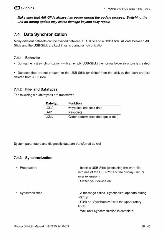
7.4.3 Synchronization
• Preparation: - Insert a USB-Stick (containing firmware-file)into one of the USB-Ports of the display-unit (orover extension)- Switch your device on
• Synchronization: - A message called ”Synchonize” appears duringstartup- Click on ”Synchronize” with the upper rotaryknob.- Wait until Synchronization is complete.
Display S Pilot’s Manual • 18.T275.2-1.0-EN 38 - 45
7 MAINTENANCE AND FIRST USE air avionics
12.1V 8.7V
Vario AVG
Device
Synchronize
Cancel
Figure 35: Synchronization menu during boot-process
7.4.4 Navigation dataButterfly has free to use worldwide Airport-Data available on the Butterfly website: www.air-avionics.com
7.4.5 Downloading recorded flightsFlights can be downloaded during startup. The chapter Flight Recording of this manual conainsmore details.
39 - 45 Display S Pilot’s Manual • 18.T275.2-1.0-EN
air avionics 8 CALCULATIONS AND INFORMATIONS
8 Calculations and Informations
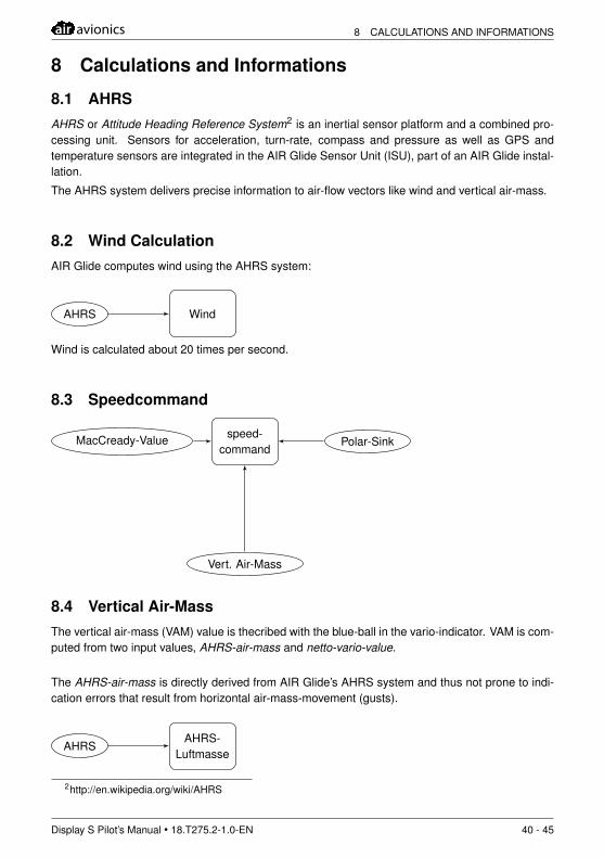
8.1 AHRSAHRS or Attitude Heading Reference System2 is an inertial sensor platform and a combined pro-cessing unit. Sensors for acceleration, turn-rate, compass and pressure as well as GPS andtemperature sensors are integrated in the AIR Glide Sensor Unit (ISU), part of an AIR Glide instal-lation.
The AHRS system delivers precise information to air-flow vectors like wind and vertical air-mass.
8.2 Wind CalculationAIR Glide computes wind using the AHRS system:
WindAHRS
Wind is calculated about 20 times per second.
8.3 Speedcommand
speed-command
Polar-Sink
Vert. Air-Mass
MacCready-Value
8.4 Vertical Air-MassThe vertical air-mass (VAM) value is thecribed with the blue-ball in the vario-indicator. VAM is com-puted from two input values, AHRS-air-mass and netto-vario-value.
The AHRS-air-mass is directly derived from AIR Glide’s AHRS system and thus not prone to indi-cation errors that result from horizontal air-mass-movement (gusts).
AHRS-Luftmasse
AHRS
2http://en.wikipedia.org/wiki/AHRS
Display S Pilot’s Manual • 18.T275.2-1.0-EN 40 - 45
8 CALCULATIONS AND INFORMATIONS air avionics
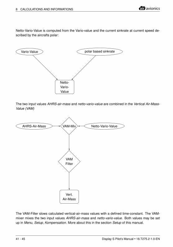
Netto-Vario-Value is computed from the Vario-value and the current sinkrate at current speed de-scribed by the aircrafts polar:
Netto-Vario-Value
Vario-Value polar based sinkrate
The two input values AHRS-air-mass and netto-vario-value are combined in the Vertical Air-Mass-Value (VAM)
VAM-MixAHRS-Air-Mass Netto-Vario-Value
VAMFilter
Vert.Air-Mass
The VAM-Filter slows calculated vertical-air-mass values with a defined time-constant. The VAM-mixer mixes the two input values AHRS-air-mass and netto-vario-value. Both values may be setup in Menu, Setup, Kompensation. More about this in the section Setup of this manual.
41 - 45 Display S Pilot’s Manual • 18.T275.2-1.0-EN
air avionics 8 CALCULATIONS AND INFORMATIONS
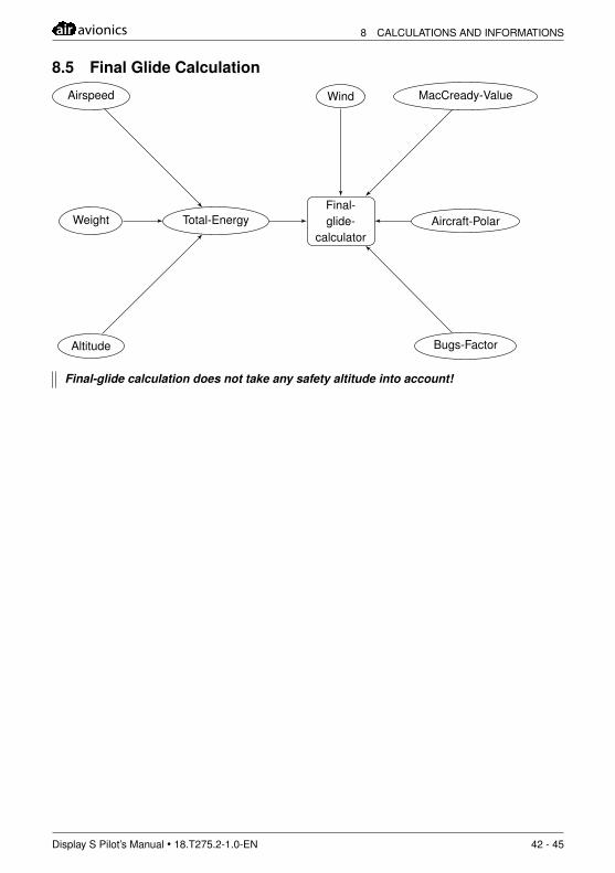
8.5 Final Glide Calculation
Final-glide-
calculatorTotal-Energy
Wind
Aircraft-Polar
MacCready-Value
Bugs-Factor
Airspeed
Weight
Altitude
Final-glide calculation does not take any safety altitude into account!
Display S Pilot’s Manual • 18.T275.2-1.0-EN 42 - 45
8 CALCULATIONS AND INFORMATIONS air avionics
Appendix I: Import of own Aircraft performance data
Behavior
After import of an own glider-file, the normal aircraft database is replaced by the imported file. Af-ter deleting the file from your Polars-Folder on the USB-stick and re-syncing, the normal aircraftdatabase is available again.
The imported file must be named glider.xml
Glider File
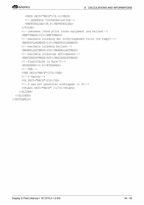
A file containing aircraft performance data is an XML file with specific datasets
Importing own glider files is only recommended for experts. Importing wrong files mayrender AIR Glide unusable!
Example
<BUTTERFLY VERSION="1" DATAFORMAT="1.0"><GLIDERS><GLIDER>
<!--name the flugzeuges muss eindeutig sein--><!--ggf muss spezielles feld fr anzuzeigende namen eingefgt werden--><NAME>ASG-29e</NAME><!--die geschwindigkeitspolare minthetens ein knoten--><POLAR><!--drei polarenpunkte--><!--alternativ knnen auch die polinom koeffizienten
angegeben werden <A>a_2</A> <B>a_1</B> <C>a_0</C>--><POINT><!--horizontal geschwindigkeit EAS--><V UNIT="KM/H">80</V><!--vertikal geschwindigkeit EAS--><W>-0.521</W>
</POINT><POINT><V UNIT="KM/H">120</V><W>-0.721</W>
</POINT><POINT><V UNIT="KM/H">200</V><W>-2.52</W>
</POINT><!--minimumgeschwindigkeit normalisiert bei gegebender flŁchenbelastung-->
43 - 45 Display S Pilot’s Manual • 18.T275.2-1.0-EN
air avionics 8 CALCULATIONS AND INFORMATIONS
<VMIN UNIT="KM/H">78.0</VMIN><!--gegebene flŁchenbelastung--><REFWINGLOAD>38.0</REFWINGLOAD>
</POLAR><!--leermass (ohne pilot loose equipment und ballast--><EMPTYMASS>333</EMPTYMASS><!--maximale zuladung der nichttragenden teile (im rumpf)--><MAXPAYLOADMASS>110</MAXPAYLOADMASS><!--maximale zuladung ballast--><MAXBALLASTMASS>200</MAXBALLASTMASS><!--maximale zulŁssige abflugmasse--><MAXTAKEOFFMASS>600</MAXTAKEOFFMASS><!--flgelflŁche in kg/mˆ2--><WINGAREA>10.8</WINGAREA><!--VNE--><VNE UNIT="KM/H">270</VNE><!--V manver--><VA UNIT="KM/H">210</VA><!--V max mit gesetzten wlbklappen (> 0)--><VFLAPS UNIT="KM/H" />270</VFLAPS>
</GLIDER></GLIDERS>
</BUTTERFLY>
Display S Pilot’s Manual • 18.T275.2-1.0-EN 44 - 45

8 CALCULATIONS AND INFORMATIONS air avionics
Notes
45 - 45 Display S Pilot’s Manual • 18.T275.2-1.0-EN