Embed Size (px)
Citation preview
I n t e g r i t y - S e r v i c e - E x c e l l e n c e
Air Force Sustainment Center
Industry Opportunities
Enabling
Cost
Effective Readiness
Mr. Kevin Stamey
Director of Engineering
Air Force Sustainment Center
1Approved for Public Release: 72ABW-2016-0038
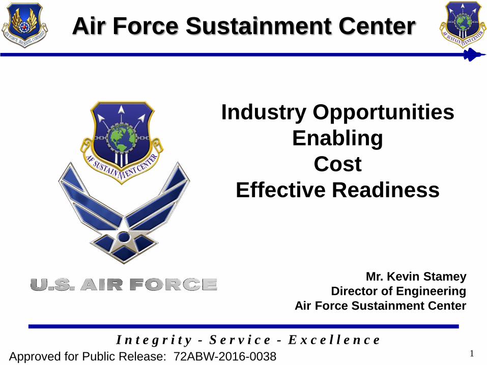
Logistics & Sustainment Enterprise 2040
LSE 2040Vision & Roadmap for the Next 30 years
Attributes
1. 100% Data
Availability
2. 100% Parts
Availability
3. Environmentally
Compliant
4. Efficient Depot
5. Effective
Workforce
6. 100% Process
Control
7. Intelligent
Sustainment
Infrastructure
8. Resilient
Mission Ready
Software
Sustainment
9. Energy Efficacy
Achieving Art-of-the-Possible Through Out-of-the-Box Innovation
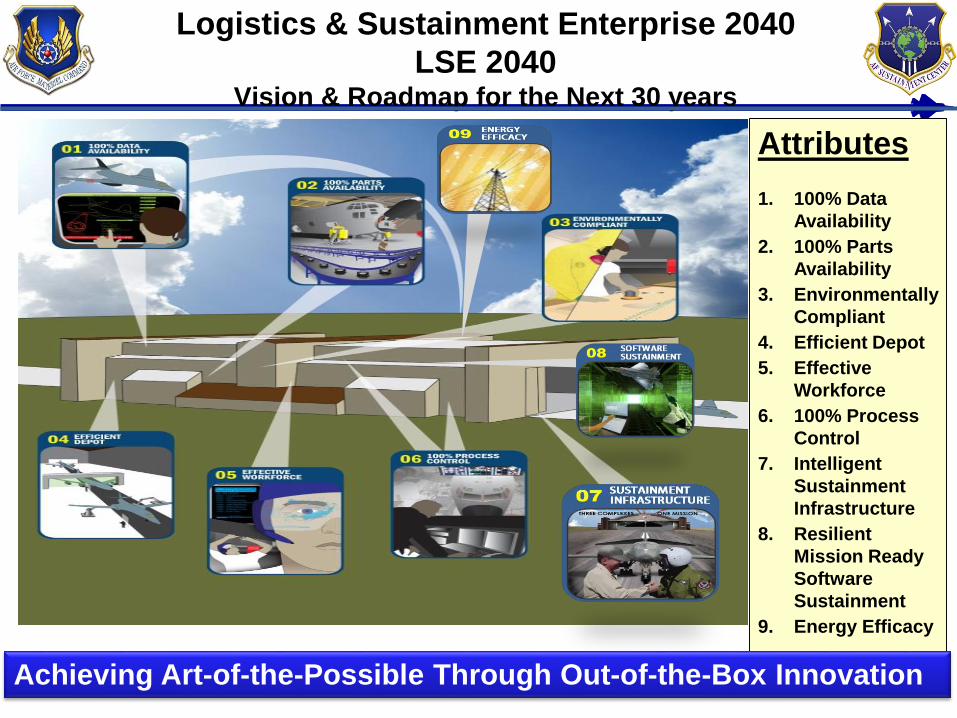
Multi-Domain Log C2Why We Need It
Log C2 processes & tools = enabled core capabilities = mission success3
1. USAF Core Logistics Capabilities, from AF Annex 4-0, Combat Support
AFSC VisionProblem Statement:The Air Force lacks the processes and
tools to conduct intelligent enterprise
Multi-Domain Logistics Command and
Control and maintain global visibility of
total logistics resources (materiel,
capabilities, and infrastructure),
resulting in the inability to effectively
and consistently set the theaters,
integrate with global and theater
planning, maintain visibility during full
spectrum operations, and reset forces.
The future AF enterprise needs: Combat Support components focused on Operations, Adaptive Basing, and the Warfighter
A Logistics Common Operating Picture (Log COP)/User-Defined Operating Picture (UDOP)
across air, space and cyber domains, providing timely, accurate information for Commanders
Full integration of Logistics into planning, current operations, and future operations
Command and Control of globally
integrated logistics synchronized
across air, space, and cyber
domains, conducted in collaboration
with theater C2, to achieve desired
effects across the spectrum of
conflict in highly contested and
denied environments while
optimizing allocation of resources
LSE 2040
Resilient, Mission Ready Software Sustainment
• Challenges
– Software Development Environments are targets for adversaries
• Systems and tools with unknown pedigrees provide adversaries
opportunities for shutting down software sustainment capability or
threaten weapon software operations
– Modern weapon system software needs to operate in an
interoperable battle-space with a diverse family of interrelated
systems
• Not tested early enough with high enough fidelity in relevant &
effective environment during sustainment phase
• Lack of fidelity during sustainment impacts warfighter requirements
validation/training techniques
• Results in higher costs and lesser quality software after fielding
• Need– Robust static and dynamic code analysis tools
– Trusted SDE tools
– High fidelity emulators of flight environment4
NDI Opportunities Abound
• NDI tools and process are 70-80 era
– Significant manual labor
– Very little automation or digital tools
– Heavily dependent on technician skill and data
interpretation; PoD varies
• NDI is a large driver of labor cost and depot flow
time
• Safety Critical: Must be accurate
– Improved PoD variance and crack size detection will
lengthen Mx Intervals
– Better tools & techniques to improve coverage
5End to End, Fully Integrated Digital NDI Capability
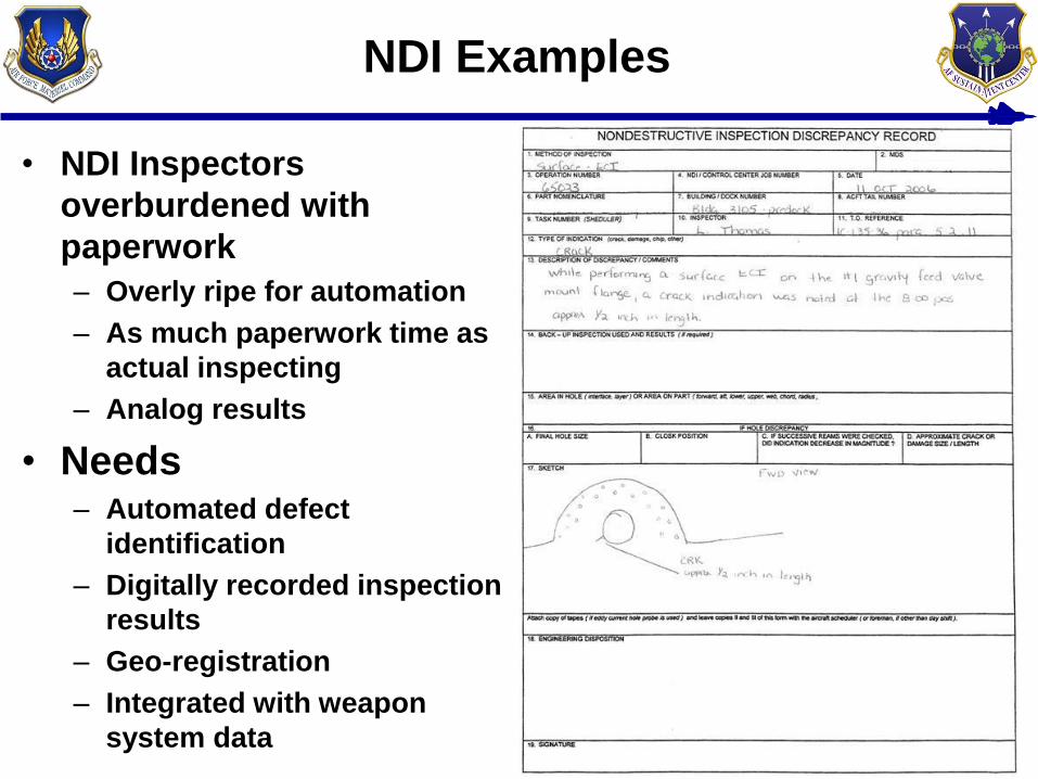
NDI Examples
• NDI Inspectors
overburdened with
paperwork
– Overly ripe for automation
– As much paperwork time as
actual inspecting
– Analog results
• Needs– Automated defect
identification
– Digitally recorded inspection
results
– Geo-registration
– Integrated with weapon
system data6
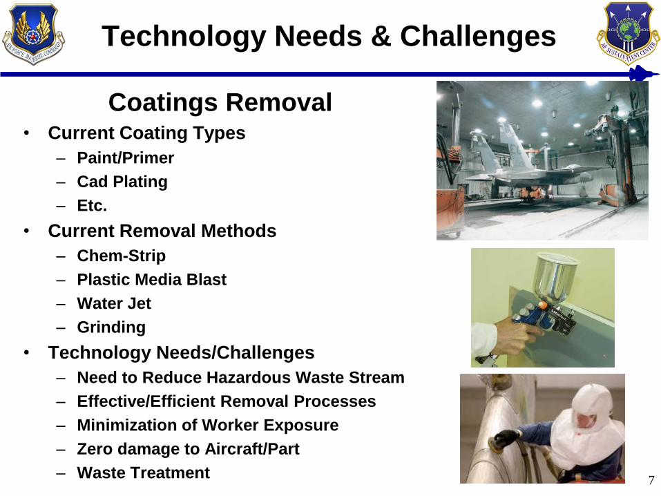
Technology Needs & Challenges
Coatings Removal• Current Coating Types
– Paint/Primer
– Cad Plating
– Etc.
• Current Removal Methods
– Chem-Strip
– Plastic Media Blast
– Water Jet
– Grinding
• Technology Needs/Challenges
– Need to Reduce Hazardous Waste Stream
– Effective/Efficient Removal Processes
– Minimization of Worker Exposure
– Zero damage to Aircraft/Part
– Waste Treatment7
Technology Needs & Challenges
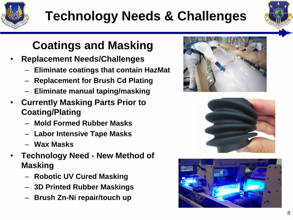
Coatings and Masking• Replacement Needs/Challenges
– Eliminate coatings that contain HazMat
– Replacement for Brush Cd Plating
– Eliminate manual taping/masking
• Currently Masking Parts Prior to
Coating/Plating
– Mold Formed Rubber Masks
– Labor Intensive Tape Masks
– Wax Masks
• Technology Need - New Method of
Masking
– Robotic UV Cured Masking
– 3D Printed Rubber Maskings
– Brush Zn-Ni repair/touch up
8
Technology Needs/Challenges
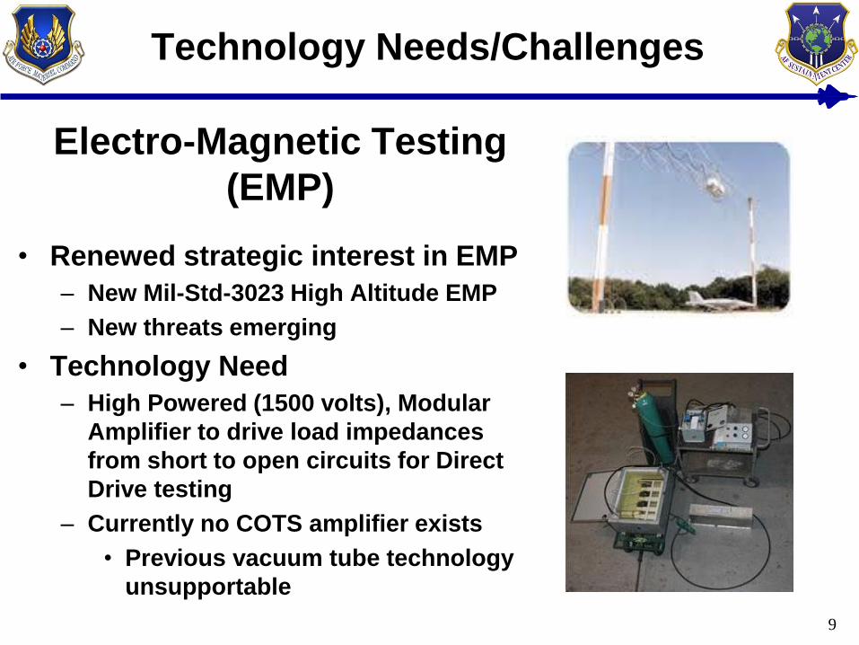
Electro-Magnetic Testing
(EMP)
• Renewed strategic interest in EMP
– New Mil-Std-3023 High Altitude EMP
– New threats emerging
• Technology Need
– High Powered (1500 volts), Modular
Amplifier to drive load impedances
from short to open circuits for Direct
Drive testing
– Currently no COTS amplifier exists
• Previous vacuum tube technology
unsupportable
9
Technology Needs/Challenges
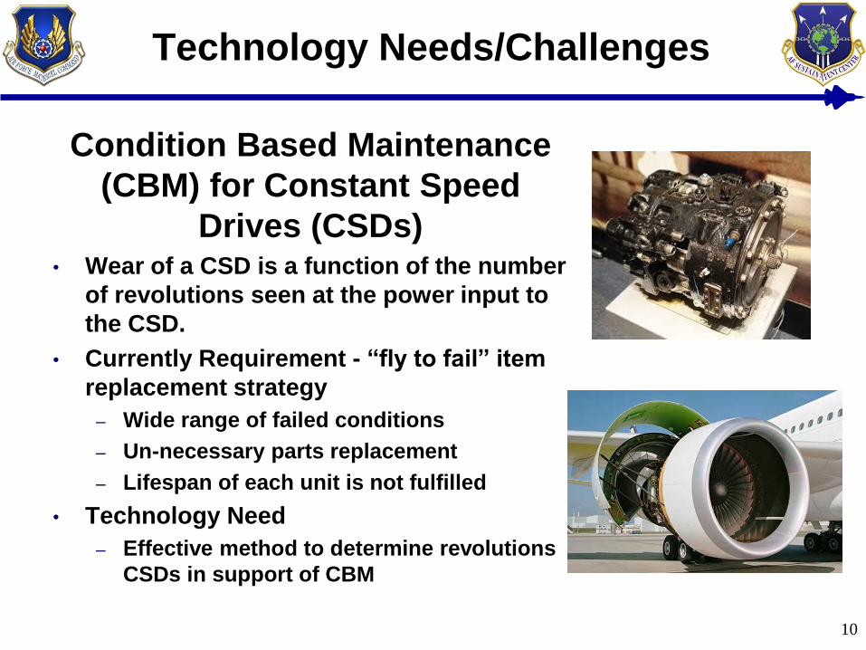
Condition Based Maintenance
(CBM) for Constant Speed
Drives (CSDs)• Wear of a CSD is a function of the number
of revolutions seen at the power input to
the CSD.
• Currently Requirement - “fly to fail” item
replacement strategy
– Wide range of failed conditions
– Un-necessary parts replacement
– Lifespan of each unit is not fulfilled
• Technology Need
– Effective method to determine revolutions
CSDs in support of CBM
10
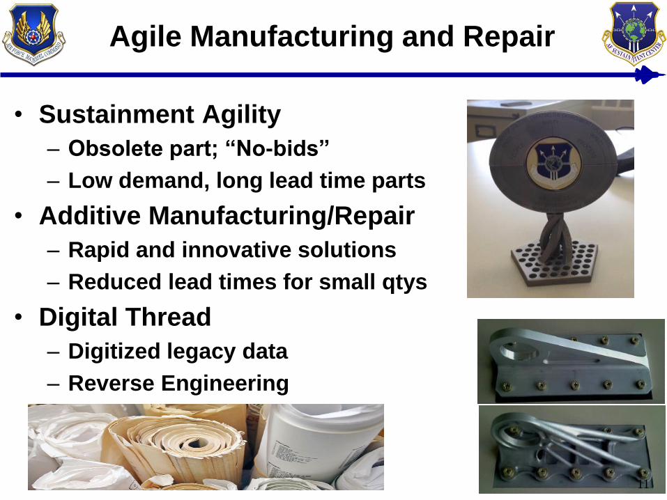
Agile Manufacturing and Repair
• Sustainment Agility
– Obsolete part; “No-bids”
– Low demand, long lead time parts
• Additive Manufacturing/Repair
– Rapid and innovative solutions
– Reduced lead times for small qtys
• Digital Thread
– Digitized legacy data
– Reverse Engineering
11
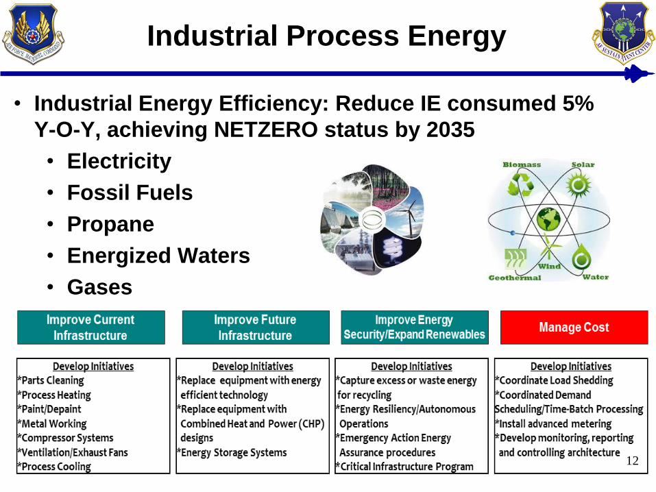
Industrial Process Energy
• Industrial Energy Efficiency: Reduce IE consumed 5%
Y-O-Y, achieving NETZERO status by 2035
• Electricity
• Fossil Fuels
• Propane
• Energized Waters
• Gases
12
Misc Tech Needs
• Automated FOD Detection
• Tech data automation/visualization
– Projected tech data
– Google glass
– Video aids
– Light weight tablet digital tech data
• Automation of quality checking
– Sensing/verification of task completion
13
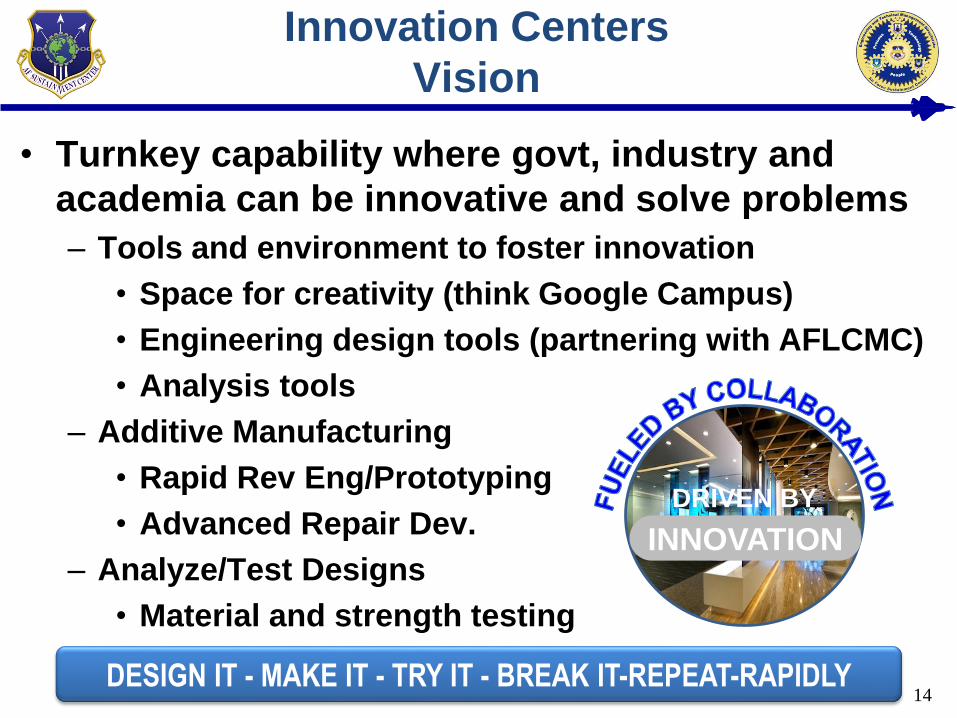
Innovation Centers
Vision
• Turnkey capability where govt, industry and
academia can be innovative and solve problems
– Tools and environment to foster innovation
• Space for creativity (think Google Campus)
• Engineering design tools (partnering with AFLCMC)
• Analysis tools
– Additive Manufacturing
• Rapid Rev Eng/Prototyping
• Advanced Repair Dev.
– Analyze/Test Designs
• Material and strength testing
14
DRIVEN BY
BYINNOVATION
DESIGN IT - MAKE IT - TRY IT - BREAK IT-REPEAT-RAPIDLY
Concept Description
• Desired capabilities:
– Polymer and metal additive manufacturing capability
– Testing and material characterization needed for part
qualification
– Post processing surface finishing
– Heat treating-preferably Hot Isostatic Press
• Business Model
– Cost sharing among “consortium” members
• Upfront investment and/or annual fees
• Govt Role
– Member and user
– Not the owner or operator of the Innovation Center
– Cooperative Research and Development Agreement
15Overarching Goal: Cost Effective Sustainment Agility

Questions?16
Backup slides for Newest Technology Needs
SBIR 17.1 Topics
17
Alternative Method of Surface Activation for Electroplating
High Strength Steel Landing Gear Parts
18
FULL DESCRIPTION:
The current blasting technique for activating surfaces prior to
plating utilizes either aluminum oxide or garnet
After the blasting the blast material is spent, and disposed of
as hazardous waste
OSHA citations have been received due to blasting processes
An alternative technology, such as Open Air Plasma (OAP),
would substantially reduce hazardous material waste
An alternate process such as OAP would only strip the first
few atom layers from the surface, compared to ten-thousandth
of an inch – potentially increasing part live
PROBLEM STATEMENT: Develop an alternative surface
activation technology for electroplating landing gear parts. The
technology shall reduce the amount of material removed from the
parts, improve plating adhesion, reduce waste, and lower risks to
both personnel & landing gear parts
TOPIC OBJECTIVE: Adhesion will be improved due to the
elimination of potential grit blast media. Also, less material will be
removed, increasing part lifespan
IMPACT IF APPROVED:
Reduce cost of overhaul of landing gear parts
Reduce disposal of hazardous waste
Increase worker safety
Decrease cost of landing gear maintenance
IMPACT IF NOT APPROVED:
Will not obtain the benefits of the listed impacts
Will continue to operate landing gear maintenance
operations ineffectively
TPOC NAME: Mr. David Astle and Mr. Dave Fredrick
ORGANIZATION: 417 SCMS/GUEA and 309th CMXG/ENL
NEED DATE:
STRATEGIC ALLIGNMENT: CoF Attributes
3) Environmentally Compliant
5) Effective Workforce
6) 100% Process Control
ENTERPRISE POTENTIAL: Multiple Landing gear / weapon
systems will be effected by this effort
DISTRIBUTION A. Approved for public release: distribution unlimited.
Electroplating 3D Printed Materials
19
PROBLEM STATEMENT: The metal plating of Fused Deposition
Modeling (FDM) parts is poorly defined with little information on
how to replicate the process. FDM parts plated with chromium,
nickel or copper can greatly enhance strength, durability, surface
hardness, and heat resistance
TOPIC OBJECTIVE: Research and develop an appropriate
process to include specifications, equipment requirements,
optimal applications and cost/benefit for metal plating 3D FDM
printed tooling.
TPOC NAME: Mr. Taylor Gittins
ORGANIZATION: MXDEZ
NEED DATE:
STRATEGIC ALLIGNMENT: CoF Attributes
2) 100% Pars Availability
4) Efficient Depot
6) 100% Process Control
ENTERPRISE POTENTIAL: This effort could impact any parts
made by FDM
FULL DESCRIPTION:
Calculated cost savings have not been accomplished due to
the maturity of the technology Expected saving from increased strength, durability and toughness of plated parts
FDM materials that may be metal plated are ASA, ABS-ESD7,
Nylon 12, Polycarbonate, or ULTEM 9085
Industry has claimed that the metal plating thickness of an
FDM part can be between 0.001 – 0.020 inches and can
improve strength by a factor of 20
The process for plating complex FDM printed parts is not well
understood from a design perspective
IMPACT IF APPROVED:
Enhance light weight FMD printed parts
Increase strength, durability and hardness of parts
Increase parts lifespan
Decrease MTBF
IMPACT IF NOT APPROVED:
Will not realize positive impacts
Slower modernization of depot maintenance
DISTRIBUTION A. Approved for public release: distribution unlimited.
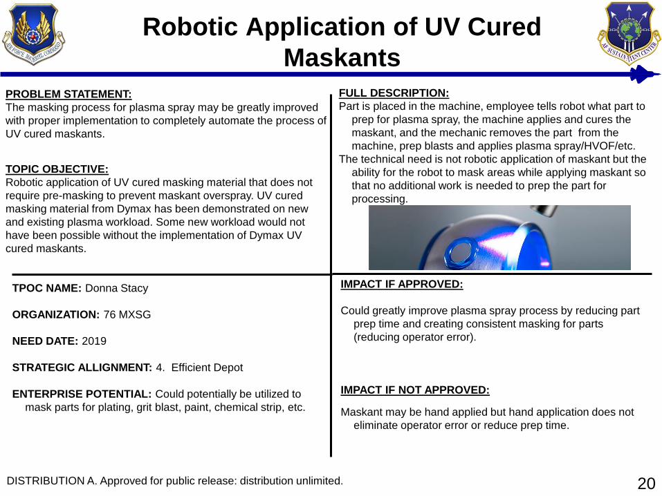
Robotic Application of UV Cured
Maskants
20
FULL DESCRIPTION:
Part is placed in the machine, employee tells robot what part to
prep for plasma spray, the machine applies and cures the
maskant, and the mechanic removes the part from the
machine, prep blasts and applies plasma spray/HVOF/etc.
The technical need is not robotic application of maskant but the
ability for the robot to mask areas while applying maskant so
that no additional work is needed to prep the part for
processing.
PROBLEM STATEMENT:
The masking process for plasma spray may be greatly improved
with proper implementation to completely automate the process of
UV cured maskants.
TOPIC OBJECTIVE:
Robotic application of UV cured masking material that does not
require pre-masking to prevent maskant overspray. UV cured
masking material from Dymax has been demonstrated on new
and existing plasma workload. Some new workload would not
have been possible without the implementation of Dymax UV
cured maskants.
IMPACT IF APPROVED:
Could greatly improve plasma spray process by reducing part
prep time and creating consistent masking for parts
(reducing operator error).
IMPACT IF NOT APPROVED:
Maskant may be hand applied but hand application does not
eliminate operator error or reduce prep time.
TPOC NAME: Donna Stacy
ORGANIZATION: 76 MXSG
NEED DATE: 2019
STRATEGIC ALLIGNMENT: 4. Efficient Depot
ENTERPRISE POTENTIAL: Could potentially be utilized to
mask parts for plating, grit blast, paint, chemical strip, etc.
DISTRIBUTION A. Approved for public release: distribution unlimited.
Constant Speed Drive (CSD) Input Shaft
Counter
21
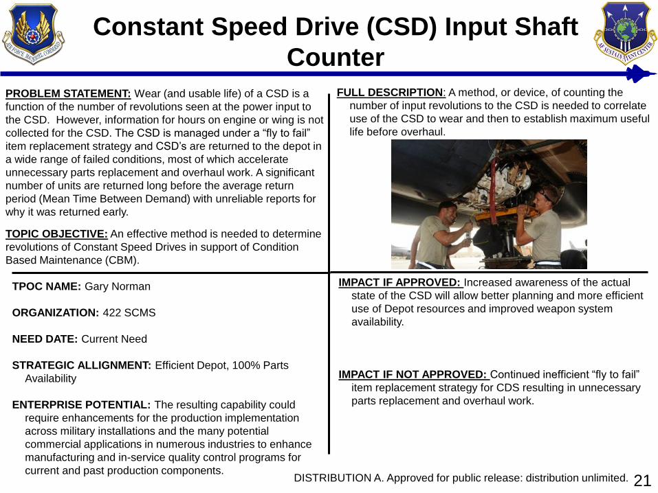
FULL DESCRIPTION: A method, or device, of counting the
number of input revolutions to the CSD is needed to correlate
use of the CSD to wear and then to establish maximum useful
life before overhaul.
PROBLEM STATEMENT: Wear (and usable life) of a CSD is a
function of the number of revolutions seen at the power input to
the CSD. However, information for hours on engine or wing is not
collected for the CSD. The CSD is managed under a “fly to fail”
item replacement strategy and CSD’s are returned to the depot in
a wide range of failed conditions, most of which accelerate
unnecessary parts replacement and overhaul work. A significant
number of units are returned long before the average return
period (Mean Time Between Demand) with unreliable reports for
why it was returned early.
TOPIC OBJECTIVE: An effective method is needed to determine
revolutions of Constant Speed Drives in support of Condition
Based Maintenance (CBM).
IMPACT IF APPROVED: Increased awareness of the actual
state of the CSD will allow better planning and more efficient
use of Depot resources and improved weapon system
availability.
IMPACT IF NOT APPROVED: Continued inefficient “fly to fail”
item replacement strategy for CDS resulting in unnecessary
parts replacement and overhaul work.
TPOC NAME: Gary Norman
ORGANIZATION: 422 SCMS
NEED DATE: Current Need
STRATEGIC ALLIGNMENT: Efficient Depot, 100% Parts
Availability
ENTERPRISE POTENTIAL: The resulting capability could
require enhancements for the production implementation
across military installations and the many potential
commercial applications in numerous industries to enhance
manufacturing and in-service quality control programs for
current and past production components.DISTRIBUTION A. Approved for public release: distribution unlimited.
Damage Tolerance Analysis of Grinding
Burn Cracks in High Strength Steels
22
FULL DESCRIPTION:
The AF wishes to better understand the fracture mechanics of
small cracks in burned HSS parts
The AF needs methods/models that can be used to manage
such cracks in LG
The AF needs to investigate the types of machining conditions
that encourage the formation of the mircro-cracks in burned
HSS
Burns in HSS LG parts commonly result in the condemnation
of the LG part
Burned LG parts have resulted in Class A Accidents
PROBLEM STATEMENT: Landing Gear (LG) are specialized
structures designed to sustain the high stresses and loads of
landing aircraft. Some LG parts are made of High Strength Steels
(HSS). During manufacture, rework, or chrome grinding there is
the potential that HSS LG parts are overheated resulting in an
under/over tempered martensitic condition (burn). A burn can
result in the formation of microstructurally and physically small
cracks in the 0.001 - 0.010 in. range
TOPIC OBJECTIVE: Develop special methods, data, or
applications for the modeling and crack growth analysis of
thermally induced cracks located in grinding burns of high
strength steel landing gear parts
IMPACT IF APPROVED:
Increased knowledge in the formation of cracks in burned
HSS
Increased safety of flight for HSS LG parts
Increased safety of future (LG and Weapon Systems)
designs that use HSS parts
Potential cost savings / avoidance
IMPACT IF NOT APPROVED:
Continue to operate HSS LG parts at an increased risk
Continue to operate at higher costs
Loss of improving future design that use HSS
TPOC NAME: Mr. Andrew Clark
ORGANIZATION: 417 SCMS/GUEA
NEED DATE:
STRATEGIC ALLIGNMENT: CoF Attributes:
3) 100% Data Integration & Availability
6) 100% Process Control
7) Intelligent Sustainment Network
ENTERPRISE POTENTIAL: Multiple Landing gear / weapon
systems will be effected by this effort
DISTRIBUTION A. Approved for public release: distribution unlimited.
Demonstration and Validation of Brush LHE Alkaline Zn-Ni
as a Brush Cadmium (Cd) Alternative
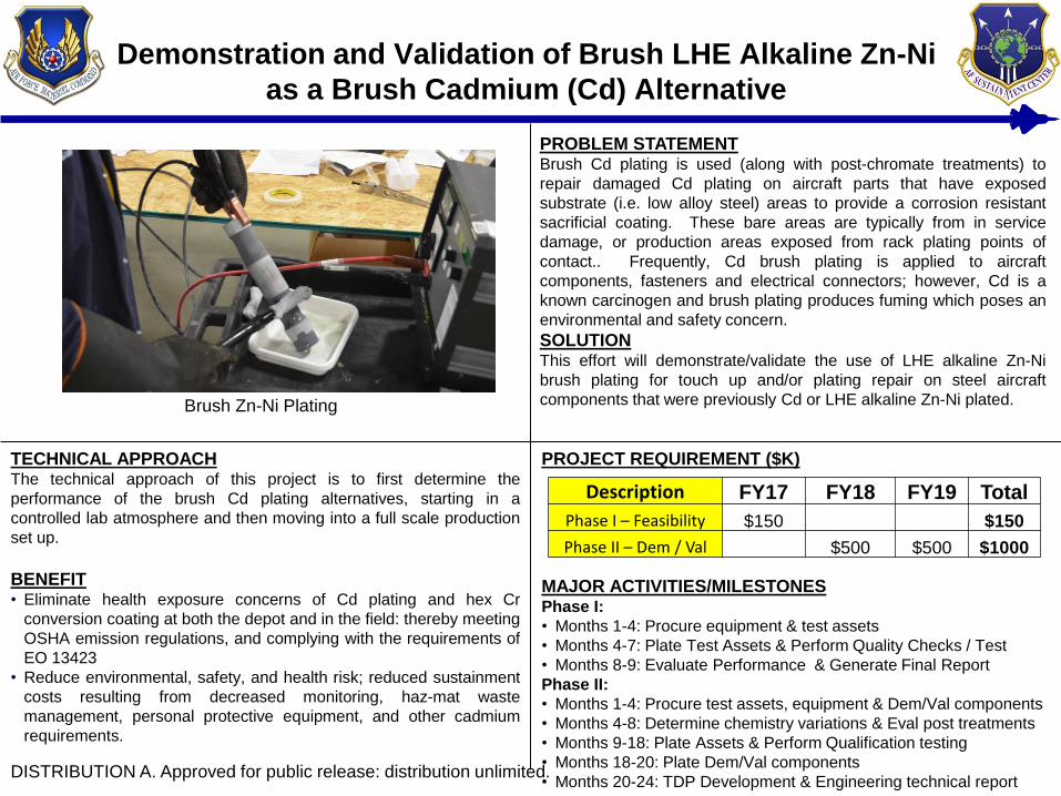
Brush Zn-Ni Plating
TECHNICAL APPROACHThe technical approach of this project is to first determine the
performance of the brush Cd plating alternatives, starting in a
controlled lab atmosphere and then moving into a full scale production
set up.
BENEFIT• Eliminate health exposure concerns of Cd plating and hex Cr
conversion coating at both the depot and in the field: thereby meeting
OSHA emission regulations, and complying with the requirements of
EO 13423
• Reduce environmental, safety, and health risk; reduced sustainment
costs resulting from decreased monitoring, haz-mat waste
management, personal protective equipment, and other cadmium
requirements.
PROJECT REQUIREMENT ($K)
MAJOR ACTIVITIES/MILESTONESPhase I:
• Months 1-4: Procure equipment & test assets
• Months 4-7: Plate Test Assets & Perform Quality Checks / Test
• Months 8-9: Evaluate Performance & Generate Final Report
Phase II:
• Months 1-4: Procure test assets, equipment & Dem/Val components
• Months 4-8: Determine chemistry variations & Eval post treatments
• Months 9-18: Plate Assets & Perform Qualification testing
• Months 18-20: Plate Dem/Val components
• Months 20-24: TDP Development & Engineering technical report
PROBLEM STATEMENTBrush Cd plating is used (along with post-chromate treatments) to
repair damaged Cd plating on aircraft parts that have exposed
substrate (i.e. low alloy steel) areas to provide a corrosion resistant
sacrificial coating. These bare areas are typically from in service
damage, or production areas exposed from rack plating points of
contact.. Frequently, Cd brush plating is applied to aircraft
components, fasteners and electrical connectors; however, Cd is a
known carcinogen and brush plating produces fuming which poses an
environmental and safety concern.
SOLUTIONThis effort will demonstrate/validate the use of LHE alkaline Zn-Ni
brush plating for touch up and/or plating repair on steel aircraft
components that were previously Cd or LHE alkaline Zn-Ni plated.
Description FY17 FY18 FY19 Total
Phase I – Feasibility $150 $150
Phase II – Dem / Val $500 $500 $1000
DISTRIBUTION A. Approved for public release: distribution unlimited.
F-16 Landing Gear Bushing Bore Repair
24
PROBLEM STATEMENT: The F-16 main landing gear (MLG)
and nose landing gear (NLG) connection points have wearable
bushings to transfer landing loads to the aircraft structure. Over
time these bushings wear and migrate out of the housing and
bulkhead bores. This may cause bushing bore to exceed tight out
of round limits and a need to oversize the bore. There are no
instructions on how to oversize the bore, nor adequate tooling for
the process
TOPIC OBJECTIVE: Develop tooling, procedures, training
materials, and drawings to repair all F-16 landing gear attachment
housing holes
TPOC NAME: Mr. Matt Fowers
ORGANIZATION: 309th AMXG/EN and AFLCMC/WWMEX (F-
16 Engineering)
NEED DATE:
STRATEGIC ALLIGNMENT: CoF Attributes
2) 100% Parts Availability
4) Efficient Depot
6) 100% Process Control
ENTERPRISE POTENTIAL: Landing gear bushing bore repair
could be used to fix F-16 weapon systems worldwide
IMPACT IF APPROVED:
Reduce TDY costs with fielded and on-site repairs
Reduce repair time by circumventing depot wait time
Increase MTBF on repaired assets
Increase aircraft availability
Provide precise and consistent results
IMPACT IF NOT APPROVED:
F-16 grounded for up to 6+ months until repair complete
No written procedures for current repair method
FULL DESCRIPTION:
Current repair method has damaged 341 bulkheads, resulting
in a replacement cost of ~$40,000 for material alone per unit
Estimated labor cost of $868K over 10 years
Damaged housing leads to increased downtime of F-16
Developed tooling and procedures must be designed to repair
the housing bores with the aircraft on jacks, with the landing
gear removed
Repair must be adaptable to both lightweight and heavyweight
configurations, which have slight differences in lug thickness
and bushing lengths
DISTRIBUTION A. Approved for public release: distribution unlimited.
Unique Modular, High Power, Cascadable Amplifier for
support of EMP Direct Drive Testing
25
FULL DESCRIPTION:
Current requirements for EMP survivability and hardness
assessment testing as defined in MIL-STD-3023, “High-
Altitude Electromagnetic Pulse (HEMP) Protection For Military
Aircraft” (21 November 2011) include Direct Drive techniques
in support of both Threat-level and Low Level Hardness
Maintenance/Hardness Surveillance.
Have spoken with representatives from Amplifier Research and
IFI about this issue and because of the small niche and the
large problem with possible damage and shutdown they are
not willing to invest in solution.
Existing Direct Drive Amplifier technology utilizes old vacuum
tube technology that is obsolete and very expensive to
maintain
PROBLEM STATEMENT:
Currently no existing Commercial-off-the-shelf product that will
support Amplifier requirements without shutdown or damage,
thereby leaving a shortfall in the ability to satisfy the requirements
of MIL-Standard 3023 and determine safety margins within
hardness/survivability of military tactical and strategic air vehicle
systems.
TOPIC OBJECTIVE:
Determine feasibility and develop concepts for a high power,
modular amplifier design to support wideband (10 kHz–2 GHz),
with minimum 10 kW Average Power, and capability to drive load
impedances from short to open circuits for Direct Drive testing.
IMPACT IF APPROVED:
Solid State solution would be able to verify safety margins on
individual mission critical systems throughout AF test articles
for compliance with Mil-STD 3023.
IMPACT IF NOT APPROVED:
Will have to fund a contractor for possible solution to
design/manufacture of Direct Drive system/amplifier.
TPOC NAME: Garland Anderson
ORGANIZATION: 559th SMXS/MXDPBA
NEED DATE: Jan 2018
STRATEGIC ALLIGNMENT: 4. Efficient Depot
ENTERPRISE POTENTIAL: Nuclear Hardness Maintenance
Hardness Surveillance Test capabilities set up at Hill and
Robins AFB, will need Direct Drive capabilities to facilitate
testing to Mil-Std 3023. Navy/Army would also benefit from
solution by replacing old, expensive to maintain amplifiers
and will test to new requirements in Mil-Std 3023.
DISTRIBUTION A. Approved for public release: distribution unlimited.
Development of Additive Manufacturing
for Landing Gear Components
26
FULL DESCRIPTION:
AM has the potential to improve LG designs
Other alloys (i.e. titanium) could improve part performance,
strength to weight ratio, weight, & corrosion resistance
USAF forecasting, planning, and procurement methods
require low quantity buys that eliminate economies of scale
An AM process could reduce the time to produce LG parts
from years to months
The AM process must be tested to provide the required data
to satisfy USAF airworthiness requirements
Design processes, metal powder combinations, manufacturing
& post processing techniques, qualification testing
requirement must be developed
PROBLEM STATEMENT: Due to the extreme operational loading
& harsh environments, Landing Gear (LG) designs have led to
manufacturing & fabrication processes that are lengthy &
expensive. Many LG components require forgings to ensure
proper grain flow to prevent fatigue failures. The forging process
adds significant costs, delays, & complexity to manufacturing LG.
Current machining methods limit LG component designs
TOPIC OBJECTIVE: Research and develop Additive
Manufacturing (AM) technologies for landing gear components to
enable testing and production of landing gear components using
AM techniques
IMPACT IF APPROVED:
Improved designs of LG parts
Improved designs will lead to safer LG part
Reduces weight of LG parts
LG parts availability will improve
Reduction in outside processing time
Improved production lead-time
Possible weight reduction
Optimized stress concentration areas
IMPACT IF NOT APPROVED:
The suboptimal process for replacing LG parts will remain
The use of non optimal LG designs will continue
TPOC NAME: Mr. Andrew Clark
ORGANIZATION: 417 SCMS/GUEA
NEED DATE:
STRATEGIC ALLIGNMENT: CoF Attributes
2 100% Parts Availability
4. Efficient Depot
6. 100% Process Control
ENTERPRISE POTENTIAL: Multiple Landing gear / weapon
systems will be effected by this effort
DISTRIBUTION A. Approved for public release: distribution unlimited.
Integrated 3-D Scan and Print
27
FULL DESCRIPTION:
The ideal situation would be a copy machine for three
dimensional objects. The object would be placed in a scanner
and a three dimensional “copy” would be produced with no
requirement for human interaction. The concept would be the
same as a paper copy machine, but the input and output
would be three dimensional objects. The output would not be
required to be detailed enough to distinguish components on a
circuit card. The main focus would be on any connectors and
that the exact size and shape was accurate so card guides
and holding fixtures could be fitted without the need for the
actual UUT.
PROBLEM STATEMENT:
Assets are difficult to obtain for TPS development, it is preferred
that we only have them in our possession for as little time as
possible. If the capability existed to create a three dimensional
model of the Asset in a short amount of time the Asset could be
“copied” and returned for use in the field until the Asset was
needed for integration.
TOPIC OBJECTIVE:
Provide the ability to link a three dimensional scanner through
software to a three dimensional printer to provide a closed system
capable of replicating form and fit of circuit card assemblies and
other avionics test hardware components with no human
interaction.
IMPACT IF APPROVED:
Development time for ITAs and TPSs would be decreased if
they were not dependent on UUT availability.
IMPACT IF NOT APPROVED:
TPS development times will continue to be affected by UUT
availability.
TPOC NAME: Simon Wayne / Scott Moody
ORGANIZATION: USAF AFMC 556 SMXS/MXDPB
NEED DATE: Est. CY2020
STRATEGIC ALLIGNMENT: N/A
ENTERPRISE POTENTIAL: Could be used in any shop on
base or in the AF that requires/uses additive manufacturing.
DISTRIBUTION A. Approved for public release: distribution unlimited.
Hardware Modeler Replacement for Digital
Device Simulation
28
FULL DESCRIPTION:
Many custom and hybrid ICs and custom electronic
components cannot be modeled in simulation software
because of their complexity and lack of technical data.
Location of the components within the SRU topology can also
prevent reverse engineering. The current hardware modeler in
conjunction with the Teradyne LASAR digital simulator has the
ability to perform this modeling. It is also able to retain input
and output patterns for entire clock cycles, and reestablish the
state of the device. The simulation results are available for
use in further simulations of the SRU. The current Air Force
family of testers, the VDATS, is equipped with Teradyne digital
test instruments that work in conjunction with the LASAR
simulator output to produce fault dictionary and guided probe
diagnostics for the VDATS test station. These diagnostics
indicate repair actions to be taken by technicians to return
defective SRUs to serviceable condition.
PROBLEM STATEMENT:
The D300 hardware modeler supports development and
maintenance of test programs used to test and indicate
repair actions for avionic circuit card assemblies. The
current hardware modeler is obsolete and no longer
supported. Current units are being used for parts to maintain
the viability of the system.
TOPIC OBJECTIVE:
Investigate the use of the VDATS Di-Series digital
subsystem (or equivalent) as a replacement for the D300
hardware modeler.
IMPACT IF APPROVED: Support for maintenance and
development of TPSs for SRUs containing components that
must be modeled is extended, and cost of reverse
engineering or loss of functional test is avoided.
IMPACT IF NOT APPROVED: Potential loss of avionics test
and repair for SRUs that depend on hardware modeling.
TPOC NAME: John Payne
ORGANIZATION: USAF AFMC 556 SMXS/MXDPA
NEED DATE: Est. CY2020
STRATEGIC ALLIGNMENT: N/A
ENTERPRISE POTENTIAL: Multiple weapon system avionic
repairs at all three ALCs are supported by TPSs that utilize
the legacy hardware modeler. LASAR and Teradyne DTIs
are used by other DoD agencies and industry.
DISTRIBUTION A. Approved for public release: distribution unlimited.