Embed Size (px)
Citation preview

NETWARS BASED STUDY OF A
JOINT STARS LINK-16 NETWORK
THESIS
Charlie I. Cruz, MSgt, USAF
AFIT/GCS/ENG/04-06
DEPARTMENT OF THE AIR FORCE AIR UNIVERSITY
AIR FORCE INSTITUTE OF TECHNOLOGY
Wright-Patterson Air Force Base, Ohio
APPROVED FOR PUBLIC RELEASE; DISTRIBUTION UNLIMITED.

The views expressed in this thesis are those of the author and do not reflect the official
policy or position of the United States Air Force, Department of Defense, or the United
States Government.

i
AFIT/GCS/ENG/04-06
NETWARS BASED STUDY OF A JOINT STARS LINK-16 NETWORK
THESIS
Presented to the Faculty
Department of Electrical and Computer Engineering
Graduate School of Engineering and Management
Air Force Institute of Technology
Air University
Air Education and Training Command
In Partial Fulfillment of the Requirements for the
Degree of Master of Science
Charlie I. Cruz, BS
Master Sergeant, USAF
March 2004
APPROVED FOR PUBLIC RELEASE; DISTRIBUTION UNLIMITED.

ii
AFIT/GCS/ENG/04-06
NETWARS BASED STUDY OF A JOINT STARS LINK-16 NETWORK
Charlie I. Cruz, BS Master Sergeant, USAF
Approved: /signed/ 9 March 2004 ____________________________________ Major Rusty O. Baldwin (Chairman) date /signed/ 9 March 2004 ____________________________________ Dr. Richard Raines (Member) date /signed/ 9 March 2004 ____________________________________ Dr. Michael Temple (Member) date

iii
Acknowledgements
I would like to thank my thesis advisor, Major Baldwin, for his guidance and
support that played a major role in the success of this thesis effort. I would also like to
recognize my thesis committee members, Dr. Raines and Dr. Temple, for their assistance
and suggestions throughout this thesis process.
Charlie I. Cruz
iv
Table of Contents
Page
Acknowledgements............................................................................................................ iii List of Figures .................................................................................................................... vi List of Tables .................................................................................................................... vii Abstract ............................................................................................................................ viii I. Introduction.................................................................................................................1 II. Literature Review........................................................................................................3 Introduction.................................................................................................................3 Global Information Grid .............................................................................................3 Global Grid .................................................................................................................4 Force Template Concepts ...........................................................................................7 Joint STARS .............................................................................................................10 Link-16 Data Link.....................................................................................................11 Link-16 Features .................................................................................................11 Hardware Architecture........................................................................................13 Time Division Multiple Access Protocol............................................................16 Transmission Access Modes...............................................................................17 Information Exchange Requirements .......................................................................18 Doctrine.....................................................................................................................20 Summary ...................................................................................................................23 III. Methodology.............................................................................................................24 Problem Definition....................................................................................................24 Goals and Hypothesis .........................................................................................25 Approach.............................................................................................................25 System Boundaries....................................................................................................26 System Services ........................................................................................................27 Performance Metrics.................................................................................................27 Parameters.................................................................................................................28 System.................................................................................................................28 Workload.............................................................................................................30 Factors.......................................................................................................................30 Network Topology..............................................................................................30 Mission................................................................................................................31 Evaluation Technique ...............................................................................................32

v
Workload...................................................................................................................33 Experimental Design.................................................................................................33 Summary ...................................................................................................................34 IV. Data Analysis............................................................................................................35 Introduction...............................................................................................................35 Throughput Results...................................................................................................35 Mean Delay Results ..................................................................................................36 Offered Load.............................................................................................................41 Analysis of Variance for Mean Delay ......................................................................41 Confidence Interval for Effects and Interactions ......................................................42 Summary ...................................................................................................................45 V. Conclusions and Future Work ..................................................................................47 Conclusions...............................................................................................................47 Future Work ..............................................................................................................49 Bibliography ......................................................................................................................50

vi
List of Figures Figure Page 1. Global Grid Reference Model [Whi01] ..........................................................................5 2. The Global Grid Vision [Whi01]....................................................................................7 3. Stacked Nets [Nor94]....................................................................................................14 4. Joint Interdiction Mission .............................................................................................27 5. System Throughput.......................................................................................................36 6. Mean Delay vs. Changing Mission...............................................................................37 7. Mean Delay vs. Network Topology..............................................................................37 8. Mean Delay vs. Number of Time Slots ........................................................................38 9. Mean Delay vs. Number of Terminals..........................................................................39 10. Mean Delay vs. Offered Load.....................................................................................39 11. Mean Delay vs. Number of Stacked Nets...................................................................40 12. Throughput vs. Number of Stacked Nets....................................................................40 13. Throughput vs. Number of Terminals ........................................................................41 14. Offered Load...............................................................................................................42 15. Mission 1 Confidence Interval for Interactions ..........................................................44 16. Mission 2 Confidence Interval for Interactions ..........................................................45 17. Mission 3 Confidence Interval for Interactions ..........................................................45 18. Stacked Net Example..................................................................................................48

vii
List of Tables
Table Page 1. IER Matrix Format [USJ03] .........................................................................................21 2. JTIDS Model Configuration .........................................................................................33 3. Workload Parameter Settings .......................................................................................33 4. Link-16 Network Topology ..........................................................................................37 5. ANOVA for Mean Delay..............................................................................................42 6. 90% Confidence Interval for Effects ............................................................................43 7. 90% Confidence Interval for Interactions.....................................................................43

viii
AFIT/GCS/ENG/04-06
Abstract
Both secure and anti-jam resistant, the Link-16 is the primary communications
channel used by the Joint Surveillance Target Attack Radar System (Joint STARS) for
the exchange of real-time tactical data among various ground, air, and sea platforms of
the United States of America and North Atlantic Treaty Organization forces. This
research explored the effect of increasing network traffic for imagery transfer to the mean
delay when operating under different network topologies. Using Network Warfare
Simulation (NETWARS), three different missions were simulated to run on five network
topologies having a different number of participants, different assigned time slots, and
stacked nets. As a result, this study determined that the Link-16 network is able to handle
the increase in network traffic, from 30 kilobits per second to 50 kilobits per second,
when using multiple stacked net configurations while assigning an adequate number of
time slots. However, because each participant is limited to 128 time slots per second, the
increased network traffic limits the communication ability of other participants.

1
NETWARS BASED STUDY OF A JOINT STARS LINK-16 NETWORK
I. Introduction
The Link-16 network was developed as a communication system for the exchange
of real-time tactical data between aircraft, ships, and ground units to provide decision-
makers the information necessary for mission success. Link-16 uses a Time Division
Multiple Access (TDMA) protocol that divides time into discrete time slots to provide
multiple and apparently simultaneous communication channels. The Link-16 network is
limited to 128 time slots per second for transmission and reception. All communication
is physically accomplished over a Joint Tactical Information Distribution System (JTIDS)
data terminal. This type of network is very difficult to manage due to the static
assignment of time slots and as a result, there are numerous Link-16 network designs for
specific missions or areas of operation. Because of its static nature, addition of a
participant into the mission requires modification and testing of the Link-16 network
designs.
The Link-16 is a network of radio terminals using frequency hopping technique
that transmits data on the available 51 different frequencies. This technique allows the
network to have multiple nets that can be stacked. Using a predetermined pseudo-
random pattern, the frequency is changed every 13 microseconds or approximately 600
times during each time slot. There are a total of 128 possible stacked nets numbered 0-
127, (each assigned a particular hopping pattern) with the number 127 reserved to
indicate a stacked net configuration [Nor94].

2
While the basic concepts of tactical data exchange served for many years by Link-
11 and Link-4A are retained, Link-16 was developed to provide for technical and
operational improvements to existing tactical data link capabilities. Because the Link-16
is not a replacement, interoperability with older links was maintained. The significant
improvements, discussed further in Chapter 2, made to the Link-16 are: nodelessness,
jam resistance, flexibility of communication operations, separate transmission and data
security, increased number of participants, increased data capacity, network navigation
features, and secure voice [Nor94].
The overall research goal is to study the effect of increasing the data transfer
requirements on the Link-16 network. For example, how well can the Joint Surveillance
Target Attack Radar System (Joint STARS) support transmitting images to fighters, Air
Operations Centers, or other units.
This chapter provides a basic introduction and the overall research goal. Chapter
II provides the background information on the Joint STARS Link-16 communication
element to include Global Information Grid, Global Grid, force template concept, Link-
16, Information Exchange Requirements, and doctrines. Chapter III includes the
methodology this research used. Chapter IV contains the results of NETWARS
simulations of the Link-16 network. Chapter V discusses research findings and future
work.

3
II. Literature Review
2.1 Introduction
This chapter provides background on a NETWARS-based study of the Joint
STARS Link-16 communication element. First, the Global Information Grid is defined.
Then, a brief discussion of the Global Grid is presented as well as its seven-layer
reference model. The concept of force templates is discussed followed by a description
of Joint STARS and its capabilities and communications channels. Some features of
Link-16, its hardware architecture and protocol are presented. Background about
Information Exchange Requirements and how they are developed is discussed. Finally,
the purpose of doctrines and the responsibilities of the Joint Forces Commander’s Staff
during a conflict is explored.
2.2 Global Information Grid
The Global Information Grid (GIG) is a globally interconnected, end-to-end set of
information capabilities, associated processes, and personnel for collecting, processing,
storing, disseminating, and managing information on demand to warfighters, policy
makers, and support personnel. The GIG consists of all owned and leased
communications and computing systems and services, software (including applications),
data, security services, and other associated services necessary to achieve Information
Superiority. It includes the National Security Systems (NSS) as defined in section 5142
of the Clinger-Cohen Act of 1996. The GIG supports all Department of Defense (DoD),
National Security, and related Intelligence Community missions and functions (strategic,
operational, tactical, and business) in war and in peace. It provides capabilities from all

4
operating locations (bases, posts, camps, stations, facilities, mobile platforms, and
deployed sites) and interfaces to coalition, allied, and non-DoD users and systems
[CRD01].
2.3 Global Grid
This section examines the Global Grid (GG), the communications infrastructure
of the Global Information Grid [Whi01]. The seven-layer reference model consisting of
Mission, Application, Service, Transport, Network, Link, and Physical Layers is also
introduced.
The GG Reference Model is shown in Figure 1. The layered model provides a
framework for all the communications-related functions and protocols, and facilitates
communication upgrades as technology advances. The model is based upon the OSI and
TCP/IP models but has some features that emphasize military communications.
Listed below are GG Reference Model Layer Definitions:
1. Mission Layer – The mission layer provides the specific aggregation of
applications from the Application Layer necessary to perform a particular
military mission. This layer was added to emphasize the concern for assuring
uniquely military capabilities are provided to the warfighter. For example,
most commercial Internet technology can be used in the GG but it has not yet
solved all of the military’s management, security, and mobile routing protocol
needs. The GG incorporates this layer which has no corresponding layer in
the other two models.

5
Figure 1. Global Grid Reference Model [Whi01]
2. Application Layer – This layer provides common and mission-specific
applications that are employed as utilities by users or other programs at the
Mission Layer. Applications are directly accessible by a user at this layer.
3. Service Layer – The service layer resolves differences in data format among
applications and provides a control structure for connections and dialogues
between applications. Applications are not directly accessible by a user at this
layer.
4. Transport Layer – This layer provides reliable end-to-end data transfer, flow
control, error recovery, and may include quality of service capabilities or the
ability to optimize network resources.

6
5. Network Layer – The network layer consists of Internetwork and Subnetwork
sublayers that transfer data across a network of networks or within a network
respectively. This layer is the same as the OSI reference model layer of the
same name and includes addressing, congestion control, and associated usage
accounting functions.
6. Link Layer – This layer provides point-to-point data transfer.
7. Physical Layer – This layer is partitioned into five sublayers.
7.1 Baseband Processing – This sublayer organizes/transmits/receives
channel symbols at appropriate rates and converts between digital and
analog signal representations.
7.2 Baseband-Intermediate Frequency (IF) Processing – This sublayer
performs frequency translation and analog processing.
7.3 IF Processing – This sublayer performs filtering and amplification.
7.4 IF-Radio Frequency (RF) Processing – This sublayer performs
frequency translation and analog processing from IF to RF.
7.5 RF Processing – This sublayer performs filtering, amplification, and
transduction (conversion to signal) with the physical media.
The GG is a military internet with a military objective to provide total global
connectivity for all information sources and information users. The idealized vision,
Figure 2, for the GG is a “publish and subscribe”, “plug and play” network, in which any
application can be plugged into the network anywhere, at any time, to help achieve
warfighting objectives.

7
2.4 Force Template Concepts
A force template is an electronic description of an entity that enables it to be integrated
into the Joint Battlespace Infosphere (JBI) with all the entities of its subcomponents
[Mar02]. This section discusses why force templates are needed, how they model
coalition units, and what information they provide to the JBI.
Figure 2. The Global Grid Vision [Whi01]
JBI provides the platform for information transfer while force templates contain
information that enables operational entities within the battlespace (and their clients) to
quickly interact with the JBI. In addition, a force template includes the context and
policy that define an entity’s contact with the JBI. Without the force template
mechanism, it becomes extremely difficult to track and manage changes to JBI content
resulting from the arrival and departure of coalition units.

8
An entity is an organization that decomposes into multiple components.
Components may be other entities (child entities) or clients. Entities typically correspond
to operational military units and the organization that supports them. Both parent and
child entities may each have their own force templates. These force templates may be
separate, but linked based on their relationship. The level at which a force template is
required reflects the modularity of the force (e.g., the level at which forces can be mixed,
matched or tasked). Clients are owned by entities and correspond to specific individuals,
systems, applications, repositories, or platforms. For example, an F-15 client may be
owned by a fighter squadron entity. A client interfaces directly with the JBI on behalf of
its owner. Unlike entities, clients do not connect to the JBI platform. Entities at any
level may own a distinct set of clients [Mar02].
Three categories characterize the content of a force template: necessary, desired,
and speculative. These categories are briefly described below [Mar02]:
1. Necessary Contents:
a. Information needed by the entity – information an entity needs to function
within the theater.
b. Information provided by the entity – information an entity can provide
within the theater.
c. The constraints associated with the above – examples are quality of
service, pedigree, preferred sources, and required delivery windows.
d. Security Information – identity and security credentials for individuals
occupying key unit positions. Public keys for specific clients (individuals,

9
platforms, or systems). Dissemination limitations on published
information.
2. Desired Contents:
a. Information Pedigree – indicators of the quality, reliability, and integrity
of entity publications.
b. Entity Description – the characteristics of the entity interfacing with the
JBI. It also includes the child entities that compose the entity.
c. Fuselets – are associated with either publications or subscriptions, i.e.,
XSLT, Excel spreadsheets, Active-X components, or Java beans. Fuselets
are associated with specific publications within the JBI (but not
necessarily by the providing entity). Fuselets are highly trusted,
lightweight programs that helps accomplish transformations of sensitive
data into a releasable form.
3. Speculative Contents:
a. Ontologies and Ontology Mappings – Ontologies are the consistent set of
terms that must be used to facilitate the information in order to achieve a
successful coalition operation [AnB01]. As a result, it is essential to
include ontologies specific to an entity, system, or related domain. These
ontologies should come with mappings to common ontologies used within
the JBI.
b. Process Models, Rules, and Constraints – are items that describe how the
entity does business (business rules) in the theater of operations.

10
c. Available Services, or Agents – describes services provided by the entity
for use by other (appropriate) JBI entities. For example, computation of
look angles for satellites, requests for surveillance of certain areas, and
agent services to determine unit personnel location and status.
2.5 Joint STARS
The Joint Surveillance Target Attack Radar System (Joint STARS) [Pik99] is a
long-range, air-to-ground surveillance system designed to detect, locate, classify, and
track ground targets in all weather conditions. The airborne platform of the Joint STARS
is installed on an E-8 aircraft, a modified Boeing 707, with multi-mode radar system.
The aircraft carries a phased-array radar antenna in a 26-foot canoe-shaped radome under
the forward part of the fuselage.
The aircraft has a service ceiling of 42,000 feet and can fly non-stop for 11 hours
(20 hours with in-flight refueling). The antenna is a multi-mode radar system capable of
operating in the following modes: wide-area surveillance, fixed target indication,
synthetic aperture radar, moving target indicator, and target classification.
The communications subsystem of the Joint STARS is composed of:
Digital Data Links:
- Surveillance and control data link (SCDL) for transmission to mobile ground
stations
- Joint Tactical Information Distribution System (JTIDS) for Tactical Air
Navigation operation and Tactical Data Information Link-J (TADIL-J)
generation and processing

11
- Satellite communications link
Voice Communication:
- Twelve encrypted UHF radios
- Two encrypted HF radios
- Three encrypted VHF radios with provision for Single Channel Ground and
Airborne Radio System
- Multiple intercom nets
2.6 Link-16 Data Link
Link-16 is the designation of a particular tactical data link used to exchange real-
time tactical data among units of the force. Link-16 uses the Joint Tactical Information
Distribution System (JTIDS) data terminal. JTIDS is a communications component of
the Link-16. The JTIDS component includes the Class 2 terminal software, hardware, RF
equipments, and the high-capacity, secure, anti-jam waveform that they generate [Nor94].
This section discusses some of the features of the Link-16 and its hardware architecture.
Finally, it provides a description of the Link-16 protocol.
2.6.1 Link-16 Features
Link-16 has four features, nodelessness, security, network participation groups,
and stacked nets [Nor94]. Each of these features is discussed below.
2.6.1.1 Nodelesnesss
A node is defined as a unit required to maintain communications. Unlike many
networks, there are no “nodes” in Link-16. One example of a node is a hub in a local
area network. Given the a hub is required to maintain communications, when it goes

12
down, the communication link goes down. Since time slots in a Link-16 network are
preassigned to each network participant, the link functions regardless of the status of any
particular unit, which makes them independent from the other participants. The closest
thing to a node in Link-16 is the Net Time Reference (NTR). An NTR is needed to start
the network, for new units to synchronize with, and to enter the network. After a network
has been established, Link-16 can continue to operate for hours without an NTR [Nor94].
2.6.1.2 Security
Both messages (bits) and transmissions (waveforms) are encrypted in Link-16.
Messages are encrypted by a KGV-8B encryption device in accordance with a specified
cryptovariable, i.e. key. Transmission security (TSEC) is provided by another
cryptovariable that determines JTIDS waveform specifics. The waveform uses frequency
hopping with a hop pattern determined by the net number and the TSEC cryptovariable.
Due to the constant relocation of the carrier frequency across the frequency spectrum, it
is difficult to detect and difficult to jam.
The TSEC cryptovariable also determines the amount of jitter in a signal. Jitter is
the delay, or dead time, that occurs at the beginning of each time slot where no pulse
energy is transmitted. Varying the amount of jitter from time slot to time slot makes it
difficult for a jammer to know when to turn on the jamming signal [Nor94].
The pseudorandom noise (PN) determined by the TSEC cryptovariable increases
the TSEC of the JTIDS signal. This is accomplished by performing an exclusive-or
operation (XOR) on 32 message bits with the 32-chip PN sequence of ones and zeroes.

13
As a result, the transmitted data appears like incoherent noise to an unintended receiver
[Nor94].
2.6.1.3 Network Participation Groups
JTIDS time slots can be allocated to one or more Network Participation Group
(NPG). An NPG is a functional grouping of Link-16 messages that support a particular
type of mission. The division of a net into functional groups allows JTIDS units to only
participate in NPGs needed for functions which they perform [Nor94].
2.6.1.4 Stacked Nets
Time slots may be used for more than one net by assigning a different frequency-
hopping pattern to each. Stacked nets (Figure 3) are nets which have the same TSEC and
MSEC cryptovariables but different net numbers. For each time slot of a Link-16, a
JTIDS Unit (JU) is either transmitting or receiving on one net. To use the stacked net
structure, each net participant must be mutually exclusive. Stacked nets are very useful
for air control purposes with mutually exclusive sets of controlling units and controlled
aircraft. Stacked nets are also useful for voice communications, providing a potential for
127 different voice circuits for each of the two voice NPGs [Nor94].
2.6.2 Hardware Architecture
This section discusses the basic equipment required in the Link-16 architecture.
Link-16 equipment is composed of the JTIDS terminal hardware and Tactical Digital
Information Link-J (TADIL-J) database. The following paragraphs provide a brief
description of each.

14
Figure 3. Stacked Nets [Nor94]
2.6.2.1 JTIDS Class II Terminal
This hardware component provides interoperability between units for both
hardware and software compatibility. Terminal configurations vary in the number and
type of Weapon Replaceable Assemblies (WRA) for specific platforms [Nor94]. Listed
below are the principal WRAs and their function:
1. Digital Data Processor (DDP) – This unit performs most message formatting
and Time Division Multiple Access management functions. In addition, Error
Detection and Correction coding is performed here.
2. Interface Unit (IU) – Provides input and output functions necessary to adapt
the DDP to a specific platform.

15
3. Secure Data Unit – A removable assembly mounted on the IU that contains
the cryptovariables required to provide both message and transmission
security for all terminal functions.
4. Receiver/Transmitter – This unit, under control of the DDP, creates the
outgoing RF stream of pulses. It has a 200-watt transmitter that transmits on
51 different frequencies on a pseudo random hopping basis.
5. High Power Amplifier – Used to boost the power of transmissions on all
shipboard terminals and E-2Cs.
6. Antennas – Each JTIDS platform has at least two antennas. The JTIDS
terminal chooses the antenna providing the best Signal-to-Noise Ratio (SNR)
for reception.
7. Notch Filter Assembly – An RF filter consisting of a dual-notch band-pass
filter and a circulator. Not installed on all platforms.
8. MIDS – The reduced volume version of the JTIDS terminal. MIDS terminals
are waveform compatible and interoperable with the JTIDS terminals.
2.6.2.2 TADIL-J
The Tactical Digital Information Link-J (TADIL-J) database provides a common
standard for various platform host computers to communicate. The database is composed
of a set of J series messages that support all battle group information exchange
requirements. Each of the J series messages is composed of TADIL-J words and are
mapped to a functional virtual circuit it supports. These virtual circuits are the Network
Participation Groups -- the building blocks of the network [Nor94].
16
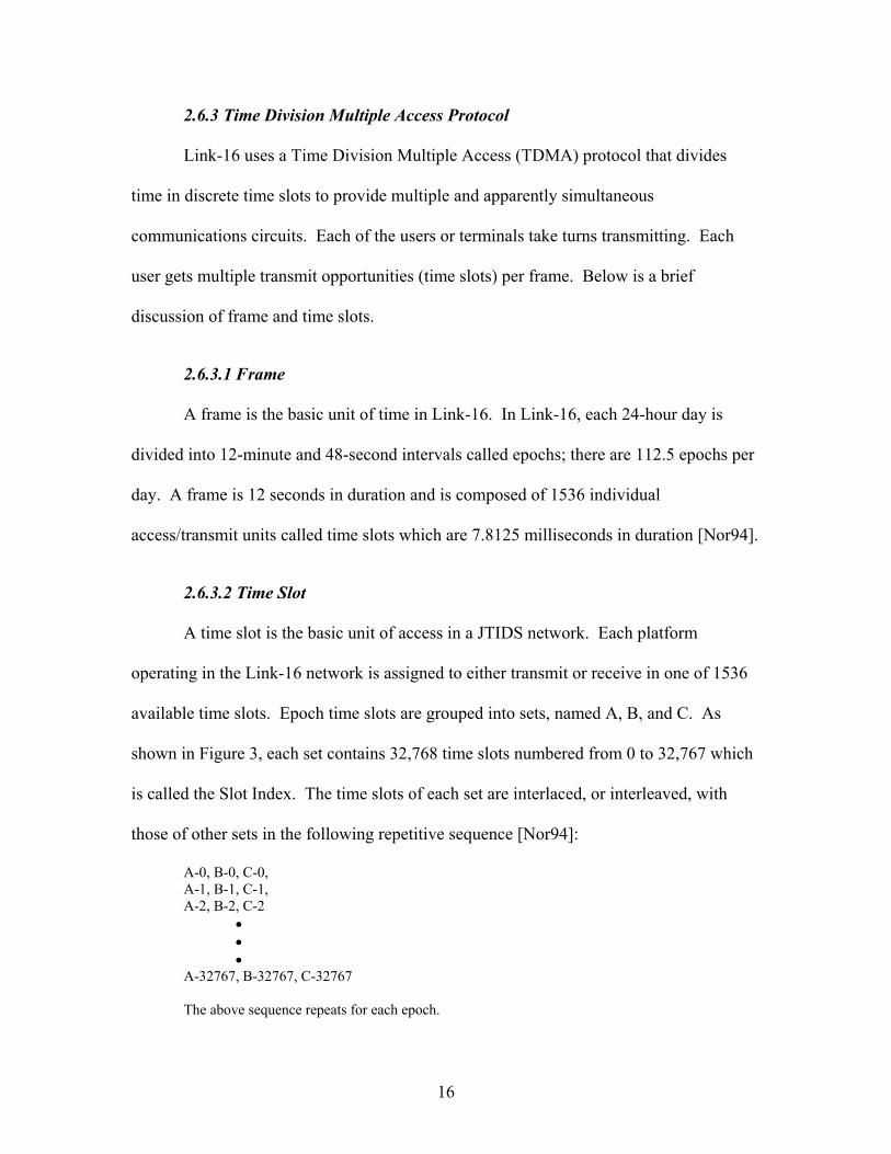
2.6.3 Time Division Multiple Access Protocol
Link-16 uses a Time Division Multiple Access (TDMA) protocol that divides
time in discrete time slots to provide multiple and apparently simultaneous
communications circuits. Each of the users or terminals take turns transmitting. Each
user gets multiple transmit opportunities (time slots) per frame. Below is a brief
discussion of frame and time slots.
2.6.3.1 Frame
A frame is the basic unit of time in Link-16. In Link-16, each 24-hour day is
divided into 12-minute and 48-second intervals called epochs; there are 112.5 epochs per
day. A frame is 12 seconds in duration and is composed of 1536 individual
access/transmit units called time slots which are 7.8125 milliseconds in duration [Nor94].
2.6.3.2 Time Slot
A time slot is the basic unit of access in a JTIDS network. Each platform
operating in the Link-16 network is assigned to either transmit or receive in one of 1536
available time slots. Epoch time slots are grouped into sets, named A, B, and C. As
shown in Figure 3, each set contains 32,768 time slots numbered from 0 to 32,767 which
is called the Slot Index. The time slots of each set are interlaced, or interleaved, with
those of other sets in the following repetitive sequence [Nor94]:
A-0, B-0, C-0, A-1, B-1, C-1, A-2, B-2, C-2 • • • A-32767, B-32767, C-32767 The above sequence repeats for each epoch.

17
2.6.4 Transmission Access Modes
There are currently three types of access modes for Link-16: dedicated,
contention, and time slot reallocation access. Dedicated and contention access modes are
currently in use, while time slot reallocation access is in development.
Dedicated access is the assignment of time slots to a uniquely identified unit for
transmission purposes. Only the assigned JTIDS Unit (JU) can transmit during that time
slot. Therefore, a slot is unused if the JU does not have any data to transmit. The
advantage of dedicated access is that it provides each JU on an NPG with a
predetermined portion of the network’s capacity and guarantee that there is no
transmission conflicts in a single-net environment. However, assets using this access
mode are not interchangeable. For example, one aircraft cannot simply replace another
aircraft. If it is necessary for this replacement to take place during an operation, the
terminal must be reinitialized to transmit and receive during time slots matching those of
the unit it would be replacing [Nor94].
Contention access is the assignment of time slots to a group of units as a pool for
transmission purposes. In this mode, each unit randomly selects a transmission time slot
from the pool. The frequency of a terminal’s transmission depends on the access rate
assigned to that terminal. The advantage of contention access is that each terminal is
given the same initialization parameters for the time slot block. This simplifies network
design and reduces the network management burden. Since JUs are not assigned a
specific time slot, JUs are interchangeable. This allows the inclusion of new participants
and allows units to be easily replaced. This feature is particularly important for aircraft,

18
and the U.S. Air Force uses contention access routinely. One disadvantage of contention
access is that there is no guarantee that a transmission is received [Nor94].
Time slot reallocation (TSR) is an access mode which allows the network
capacity of NPG to be assigned dynamically based on the projected needs of its
participants. TSR allows network capacity to be distributed where it is needed, as it is
needed, by periodically allocating time slots from a pool to each participant. Each unit
reports its transmission requirements over the network and algorithms within the terminal
redistribute the pool of time slots to meet them. If the requirement exceeds the available
capacity, time slots are redistributed to participating units in proportion to their
requirements so that there is a graceful degradation of the link. TSR can eliminate the
need for the design option files currently used to reallocate NPG capacity at initialization
time [Nor94].
2.7 Information Exchange Requirements
Information exchange requirements (IER) describe the information passed
between and among forces, organizations, or administrative structures. IERs identify
who exchanges what information with whom, as well as, why the information is needed
and how it is used. The quality (i.e., frequency, timeliness, security) and quantity (i.e.,
volume, speed, and type of information such as data, voice, and video) are attributes of
the information exchange included in the information exchange requirement [CJC01a].
Essentially, an IER is a detailed description of the operational architecture (or
business process) for a mission or function. An operational architecture is the structure
of components, their relationships, and the principles and guidelines governing their

19
design and evolution over time. The fields of an IER are shown in Table 1 and briefly
described below.
1. Rationale/Universal Joint Task List (UJTL) – Select the most appropriate task
from the UJTL or Service/Joint Mission Essential Task List.
2. Event/Action – List all events in the Mission Assessment Process that requires
information to be exchanged from a sender and receiver. Events are specific
trigger for a specific IER. For example, if the activity is “Launch missile,”
launching a missile would trigger a number of IERs. Therefore, activities
must be broken down into individual, sequenced events to correctly identify
the IERs that those events triggered.
3. Information Characterization – Define, in enough detail for system
engineering developers and testers, the general description of the information,
how and what it is used for, and the detailed information elements supporting
the exchange of information.
4. Sending Node – List all senders associated with the events mapped in the
Mission Assessment Process. Use general descriptions of the sender, such as
fighter aircraft instead of F-16.
5. Receiving Node – List all receivers associated with the events mapped in the
Mission Assessment Process. Use general descriptions of the receiver, such
as fighter aircraft instead of F-16.

20
6. Critical – Criticality is derived from the Cost of Failure analysis in the
Concept of Operations.
7-9. Attribute Fields – There are 3 required attribute fields – Format, Timeliness,
and Classification.
10-12. Optional Fields – There are many potential uses for the optional fields
such as studies, lessons learned, real world observations, etc., which assist
the review and approval process. Linking the IER to other IERs or
identifying supporting tasks can also be shown in the optional field.
Another very important use of the optional field is to provide any
additional information to help developers, testers, and reviewers better
understand data contained in the IER.
2.8 Doctrine
There are numerous Joint Doctrines to guide the employment of joint forces
[JP01a] [JP02] [JP97]. This section covers the Joint Doctrine for Targeting [JP02]. First,
the Doctrine is defined. Then, the purpose of targeting and JFC Staff responsibilities are
described.
As defined by Joint Publication 1-02 [JP01b], fundamental principles that guide
the employment of forces of two or more Services is a coordinated action toward a
common objective.

21
Table 1. IER Matrix Format [USJ03]
The purpose of targeting is to provide a framework to develop warfighting
solutions to meet a joint force commander’s (JFC) objectives. Within military
operations, targeting is focused on achieving specific effects in support of the JFC’s
objectives or subordinate component commander’s objectives. Targets fall into two
broad categories: planned and immediate. Planned targets are those known to exist in an
operational area with actions scheduled against them to generate the effects desired to
achieve JFC objectives. Immediate targets are those that have been identified too late to
be included in the normal targeting process, and therefore have not been scheduled.
Immediate targets have two subcategories: unplanned and unanticipated [JP02].

22
With the advice of subordinate component commanders, JFCs set priorities,
provide clear targeting guidance, and determine the weight of effort to be provided to
various operations. Subordinate component commanders identify high-value and high-
payoff targets for acquisition and attack, employing their forces in accordance with the
JFC’s guidance to achieve missions and objectives assigned by the JFC. The JFC
establishes the joint targeting process within an organizational framework optimized for
targeting operations. A primary consideration in this framework is the joint force’s
ability to coordinate, deconflict, prioritize, synchronize, integrate, and assess joint
targeting operations. The JFC is responsible for all aspects of the targeting process, from
establishing objectives, coordination and deconfliction between component commanders,
through combat assessment [JP02].
The following describes the responsibilities of the JFC Staff [JP02]:
1. Operations Directorate, J-3, assists the JFC in the discharge of assigned
responsibility for the direction and control of operations, beginning with
initial planning, follow-through, and completion of specific operations. In this
capacity, the directorate plans, coordinates, and integrates operations.
2. Intelligence Directorate, J-2, intelligence collection efforts, analysis,
validation, and battle damage assessment for all joint operations. In addition,
J-2 has critical input to the J-3 and J-5 in the form of an adversaries course of
action assessments essential to the joint target prioritization process and
identification of high-value/high-payoff targets.

23
3. Logistics Directorate, J-4, identifies logistic issues unique or specific to
targeting. J-4 compares the operational logistic plans to developing target lists
to ensure protection of infrastructure and/or supplies required to support
current and future operations.
4. Plans Directorate, J-5, when included performs the long-range or future joint
targeting planning. Planning is conducted by various organizations in
conjunction with J-3.
2.9 Summary
This chapter provides foundational information for a NETWARS-based study of
the Joint STARS Link-16 communications element. The Global Information Grid is
defined in which one of the components is the Link-16 communications element that
plays a role in achieving information superiority. The Global Grid with its Global Grid
Reference Model is introduced and how it relates to the OSI and TCP/IP Reference
Models. Force template concepts are discussed to explain why force templates are
needed, how they model coalition units, and what information they provide to the JBI.
The description, capabilities, and communications channel of Joint STARS are also
discussed. The features, hardware architecture, and the protocol of the Link-16
communications element are discussed in order to understand its architecture.
Information Exchange Requirements is also discussed since this element is the one that
generates network traffic in NETWARS. Finally, the discussion of how doctrines are
used to guide the employment of joint forces during any contingencies.

24
III. Methodology
3.1 Problem Definition
A Link-16 network [Nor94] is a Time Division Multiple Access (TDMA)
protocol. This protocol divides time into discrete time slots to provide multiple and
apparently simultaneous communications circuits. The Link-16 network provides a
communication channel for the exchange of, among other things, real-time tactical data
among various ground, air, and sea platforms of the U.S. and NATO forces. For
example, Joint STARS is a long-range, air-to-ground surveillance system designed to
locate, classify, and track ground targets. This aircraft transmits surveillance data to the
strike aircraft (fighter or bomber) using the Link-16 network. Due to the importance of
the tactical data exchanged in the network, it is imperative that all participating terminals
receive and send tactical data in a timely and reliable manner to accomplish the mission.
To participate in a Link-16 network, each terminal is assigned one or more time slots to
transmit or receive data. Therefore, it is crucial for the Link-16 network managers to
assign sufficient capacity to all participating terminals before mission execution. The
capacity assigned is dependent upon the product size and update rate that each terminal
produces as specified in the IER database [CJC01a]. Although other communication
networks exist, the focus of this research is the Link-16 element. While the Link-16
network is capable of data and voice communication, the focus of this study is on data
communication.

25
3.1.1 Goals and Hypothesis
The goal of this research is to study the effects of increasing the data transfer
requirements to the Link-16 network. One useful application for an increase in data
transfer requirement is for the Joint STARS to transfer captured images securely and
reliably to fighters, Air Operations Centers, or other units. It is hypothesized that the
Link-16 network is able to handle the additional network load when given a multiple
stacked net configuration; however, the capability to communicate with the other
participants due to the limited amount of time slots available is decreased.
3.1.2 Approach
To accomplish this goal, an Interdiction Mission [ESC01] is used as the basis for
a NETWARS scenario. An interdiction operation is conducted to divert, disrupt, delay,
or destroy the enemy’s surface military potential before it can be used effectively against
friendly forces [JP97]. It is assumed that the Link-16 network is already in operation.
For example, a Joint STARS aircraft is in the area of operation broadcasting collected
surveillance data to the Link-16 network. Before strike aircraft take-off, mission
essential data is pre-loaded according to an Air Tasking Order. Assuming there is no
Link-16 network available to the strike aircraft while en route to the area of operations,
updates are required when they reach the line of sight range (300 nm) of the operating
Link-16 network. Although Link-16 can be received at ranges up to 500 nm with the use
of a relay terminal, a normal range of 300 nm is used. As soon as the strike aircraft enter
the Link-16 network operating in theater, they receive updated data via the Link-16

26
network. The strike aircraft also send status updates using the Link-16 network. The
real-time tactical data exchanges are measured at this point.
3.2 System Boundaries
As depicted in Figure 4, the System Under Test (SUT) for this study consists of
all USAF aircraft involved in an Interdiction Mission exchanging data with the strike
aircraft using Link-16. Although other ground elements such as Air Operations Centers
or Control and Reporting Centers are involved, only USAF aircraft are used for the
simulation scenario. The Component Under Test (CUT) for this study is the Link-16
network element.
The E-3 Sentry is an airborne warning and control system (AWACS) aircraft that
provides all-weather surveillance, command, control and communications needed by
commanders of U.S., NATO and other allied air defense forces [Air00].
The EC-130E ABCCC is a modified C-130 “Hercules” aircraft that is used as an
Airborne Battlefield Command and Control Center (ABCCC). The ABCCC functions as
a direct extension of ground-based command and control authorities, with a primary
mission of providing flexibility in the overall control of tactical air resources [Fed99].
The RC-135V/W Rivet Joint reconnaissance aircraft supports theater and national
level consumers with real-time on-scene intelligence collection, analysis and
dissemination capabilities [Air01].

27
3.3 System Services
The system provides transmission of situational awareness data provided by the
Intelligence, Surveillance, and Reconnaissance (ISR) aircraft. Strike aircraft also
broadcast their current status using the system. Possible system outcomes include:
messages received successfully, messages received in error, and messages not received at
all.
Figure 4. Joint Interdiction Mission
3.4 Performance Metrics
The following metrics are used:
1. Mean Delay – This metric is measured in seconds. This is the elapsed time of
message delivery as measured from when a transmitting terminal receives the
data to be transmitted and the receiving terminal receives the last bit of the
message.
2. Throughput – Throughput is defined as the mean throughput of the Link-16
network and is measured in bits per second.
System
Joint STARS AWACS
Link-16 Network
ABCCC Rivet Joint
Strike Aircraft Data
Transmission
Component Under Test

28
3.5 Parameters
3.5.1 System
1. Data Packing Option – The data packing option affects how much data is
transmitted over the network. Four packing options for JTIDS data are
described below [Nor94]:
o Standard Double Pulse – This data packing option is the most anti-jam
resistant and has the lowest throughput. It transmits three words per slot
consisting of 70 bits of data per word for a total of 210 bits per slot. Data
is sent twice for redundancy. This research only uses this data packing
option.
o Packed-2 Single Pulse – This data packing option transmits six words per
slot that also consists of 70 bits of data per word for a total of 420 bits per
slot. Data is sent once with this packing option.
o Packed-2 Double Pulse – This data packing option transmits the same
amount of data as the Packed-2 Single Pulse which is 420 bits per slot.
The difference between the Packed-2 Single Pulse and the Packed-2
Double Pulse is that data is sent twice for redundancy with this data
packing option.
o Packed-4 Single Pulse – This data packing option has the highest
throughput and also the least anti-jam resistance. It transmits twelve
words per slot that consists of 70 bits of data per word for a total of 840
bits per slot. Data is sent once with this packing option.

29
2. Message Type – The message type affects how much data is transmitted over
the network. For example, in a fixed-format message, a word consists of 75
bits of which only 70 bits are data. In a free-text message, all 75 bits are data.
Only fixed-format message, which is equivalent to 70 bits of data, are used
herein [Nor94].
3. Range – This is the line of sight range between aircraft. A normal range is
defined as 300 nautical miles. An extended range is defined as 500 nautical
miles with the use of relay with other terminals. The normal range was used
for this study [Nor94].
4. Network Participation Groups (NPG) – This is a functional grouping
according to the type of messages a terminal transmits. For example, NPG-7
is surveillance, messages exchanged on this NPG are: air, surface, and
subsurface tracks, land point surface to air missile sites, and reference points
[Nor94].
5. Transmission Access Mode – There are three types of access modes for Link-
16: dedicated, contention, and time slot reallocation access. The dedicated
access mode was used because this is the most common mode used by United
States of America and North Atlantic Treaty Organization forces.
6. Stacked Nets – There are 127 possible stacked nets available in a Link-16
network, they are particularly useful for air control purposes and voice
communications [Nor94]. The number of stacked nets in operation is used as
a factor.

30
3.5.2 Workload
1. Terminals and Stacked Nets – This is the number of terminals and stacked
nets used. This parameter is chosen as a factor to vary the number of
terminals participating in the network and the number of stacked nets used in
the network, thus affecting end-to-end delay and system throughput.
2. Capacity – The assigned capacity of a terminal participating in the Link-16
network affects how much data a terminal can transmit at a given time. This
parameter is chosen as a factor.
3.6 Factors
The following factors and their corresponding levels are deemed the most
significant for this research based on pilot studies.
3.6.1 Network Topology
1. Network 1:
o Number of participants: 6
o Stacked nets used: 1
o Time slots in use per frame: 768
o Maximum data rate: 768 x 210 bits = 161,280 bits per frame (13,440
bps)
2. Network 2:
o Number of participants: 12
o Stacked nets used: 3
o Time slots in use per frame: 2,880

31
o Maximum data rate: 2,880 x 210 bits = 604,800 bits per frame
(50,400 bps)
3. Network 3:
o Number of participants: 18
o Stacked nets used: 3
o Time slots in use per frame: 3,456
o Maximum data rate: 3,456 x 210 bits = 725,760 bits per frame
(60,480 bps)
4. Network 4:
o Number of participants: 24
o Stacked nets used: 4
o Time slots in use per frame: 4,608
o Maximum data rate: 4,608 x 210 bits = 967,680 bits per frame
(80,640 bps)
5. Network 5:
o Number of participants: 24
o Stacked nets used: 5
o Time slots in use per frame: 4,608
o Maximum data rate: 4,608 x 210 bits = 967,680 bits per frame
(80,640 bps)
3.6.2 Mission
1. Mission 1: Offered load of 6,720 bps is the approximate amount of data
exchanged during an exercise or training mission.
32
2. Mission 2: Offered load of 30,000 bps is the approximate amount of data
exchanged during a counterair mission that emphasizes air situational
awareness and ground-to-air threat updates to the pilot [ESC01].
3. Mission 3: Offered load of 50,103 bps is the amount of data exchanged
from mission 2 (30,000 bps) plus an additional 20,103 bps to transmit
images.
3.7 Evaluation Technique
Simulation using NETWARS 2003-1 [Net03] is used as the evaluation technique
for this study. This evaluation technique provides repeatable results in a controlled
environment. The NETWARS JTIDS model used for this study was developed by the
Space and Naval Warfare Systems Center San Diego (SSCSD), Modeling and Simulation
Branch [Nav03]. At the time of writing this document, the required Verification and
Validation document that SSCSD is required to submit to the Defense Information
Systems Agency is currently in draft status. Therefore, a similar validation was
completed to ensure a valid model was used for the NETWARS simulations.
The validation model configuration included two Operational Facilities (OPFAC)
each consisting of the JTIDS terminal model configured as shown in Table 2. Network
traffic was sent at a constant rate of 70 bps. NETWARS reported an average mean delay
of 2 seconds. With the JTIDS model configuration in Table 2, the JTIDS terminal has a
recurrence rate of one slot every 3 seconds. Therefore, the calculated expected delay is
the average time a message must wait for a slot, plus the message transmission time
within the slot. Since the messages arrive every second, three messages were sent during

33
each slot. When the messages arrive at the terminal, they must wait 1, 2, and 3 seconds
for an available slot to come around for an average of 2 seconds.
Table 2. JTIDS Model Configuration
TSB Attribute Name JTIDS_0 JTIDS_1 slot_type T R msg_cat 7 7 Set A A Index 0 0 RRN 8 8 Net 0 0 relay_delay 0 0 TSEC 0 0 packing P4SP P4SP 3.8 Workload
Table 3 shows the workload parameters and settings used for this research. The
network load placed on the five different network topologies considered under study
affects the mean delay of the Link-16 network.
Table 3. Workload Parameter Settings
Workload Parameter Network Traffic Settings (bps) Mission 6,720/30,000/50,103
3.9 Experimental Design
The experimental design of this study consists of one factor at five levels and one
factor of three levels. Therefore, the number of required experiments for this study is 5 X
3 = 15. The total number of replications for each experiment is five, discovered
sufficient from running pilot studies. Therefore, the total number of simulations is 15
experiments X 5 replications = 75 simulations.

34
3.10 Summary
This chapter discussed the methodology used. The problem associated with the
use of the Link-16 element by various ground and air platforms was defined. The goal of
the research is stated. An approach to achieve the goal was discussed. The system is
defined and system boundaries were stated. This chapter also provided a list of services
the system provides and their possible outcomes. End-to-end delay and throughput, the
two metrics used for this study were described. System and workload parameters were
identified along with a discussion of how each parameter affects system performance.
NETWARS 2003-1 is used as the evaluation technique. Also presented are the workload
parameters and corresponding settings used for the scenario. Finally, the experimental
design was discussed.

35
IV. Data Analysis
4.1 Introduction
This chapter discusses the result of the NETWARS simulation of the Link-16
network conducted for this study. A total of five replications were run which are
sufficient to achieve a 90% confidence interval. The first result discussed is the
throughput of the Link-16 network, including an explanation of why throughput is
equivalent to network load. Then, a discussion of how network topology changes
decrease the mean delay of the Link-16 network. The next section shows the offered load
of the system. Then, an ANOVA on mean delay is presented with further discussion on
significant factors. Finally, the confidence intervals of effects and interactions are
presented and discussed.
4.2 Throughput Results
As shown in Figure 5, system throughput is equivalent to network load on the
network. This is a result of using dedicated access modes in the JTIDS terminals;
contention of time slots is not an issue. In addition, the appropriate amount of time slots
were assigned to each JTIDS terminal to handle the data transmission, except for network
1 running missions 2 and 3 where the network topology does not have enough time slots
available to support those two missions. As a result, the number of stacked nets in-use
(Figure 12) and number of participants (Figure 13) did not affect the system throughput
as long as there are a sufficient number of times slots assigned to each terminal.

36
0
10000
20000
30000
40000
50000
60000
Msn 1 Msn 2 Msn 3
bps
Network 1Network 2Network 3Network 4Network 5
Figure 5. System Throughput
4.3 Mean Delay Results
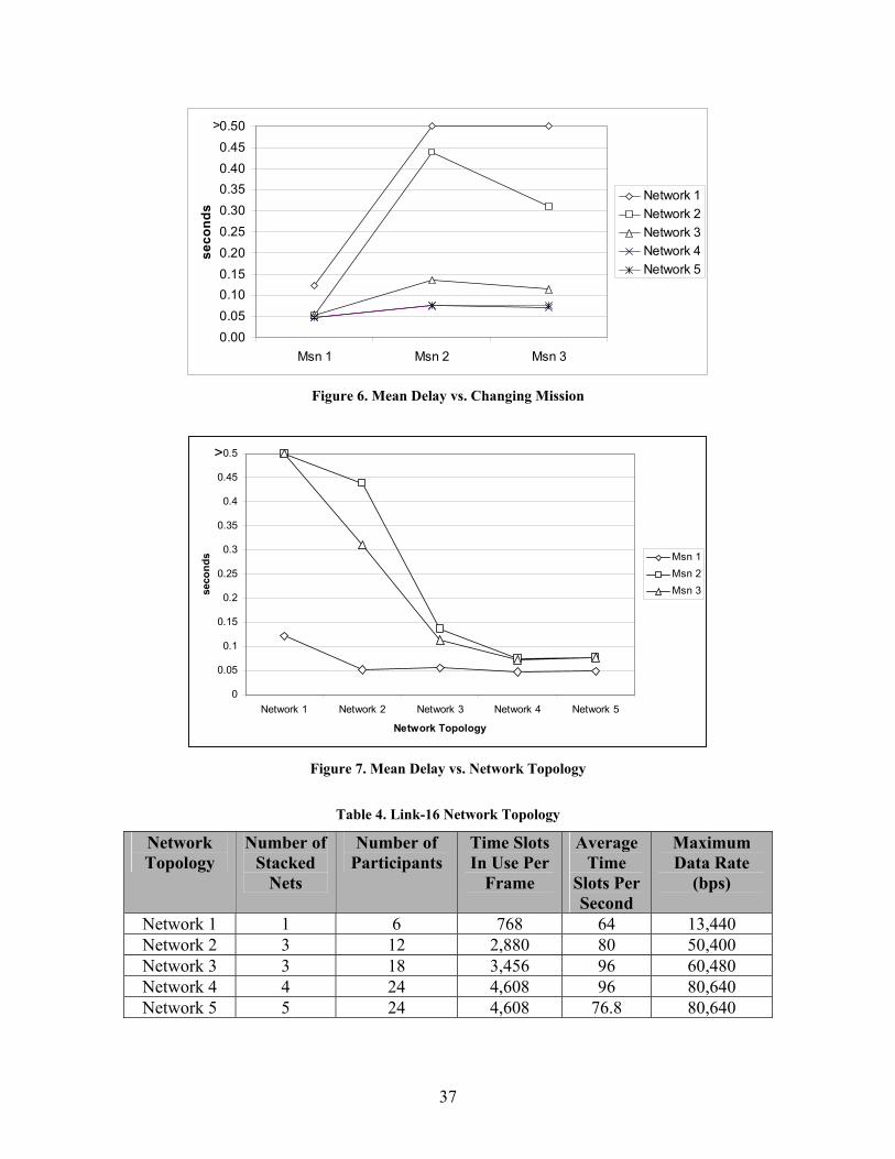
Figure 6 shows the mean delay of the Link-16 network used for this study.
Simulations were not conducted on network 1 under missions 2 and 3 because these
conditions overloaded the terminals, resulting in mean delays greater than 0.5 seconds.
The mean delay decreased for networks 2 through 5 in going from missions 2 to 3 due to
the assignment of 96 time slots per second on one of the terminals exclusively for image
transfer. Although this resulted in a decrease in system mean delay, all participants
operating on this particular stacked net are left with only 32 time slots per second (6,720
bps) available to communicate with the other participants.
Figure 7 shows the mean delay of the Link-16 network decreases as the network
topology is changed. For example, on mission 1, going from network 1 to network 2,
there was a mean delay decrease as the number of time slots assigned increased. Table 4
summarizes the network topology parameters conducted for this study.
37
0.000.050.100.150.200.250.300.350.400.450.50
Msn 1 Msn 2 Msn 3
seco
nds
Network 1Network 2Network 3Network 4Network 5
>
Figure 6. Mean Delay vs. Changing Mission
0
0.05
0.1
0.15
0.2
0.25
0.3
0.35
0.4
0.45
0.5
Network 1 Network 2 Network 3 Network 4 Network 5
Network Topology
seco
nds Msn 1
Msn 2Msn 3
>
Figure 7. Mean Delay vs. Network Topology
Table 4. Link-16 Network Topology
Network Topology
Number of Stacked
Nets
Number of Participants
Time Slots In Use Per
Frame
Average Time
Slots Per Second
Maximum Data Rate
(bps)
Network 1 1 6 768 64 13,440 Network 2 3 12 2,880 80 50,400 Network 3 3 18 3,456 96 60,480 Network 4 4 24 4,608 96 80,640 Network 5 5 24 4,608 76.8 80,640

38
As shown in Figure 8, the mean delay decreases when there are more time slots
assigned to a terminal.
0
0.05
0.1
0.15
0.2
0.25
0.3
0.35
0.4
0.45
0.5
0 50 100 150 200 250 300 350 400
# of Time Slots
Mea
n D
elay
(sec
)
Mission 1Mission 2Mission 3
>0.5
Figure 8. Mean Delay vs. Number of Time Slots
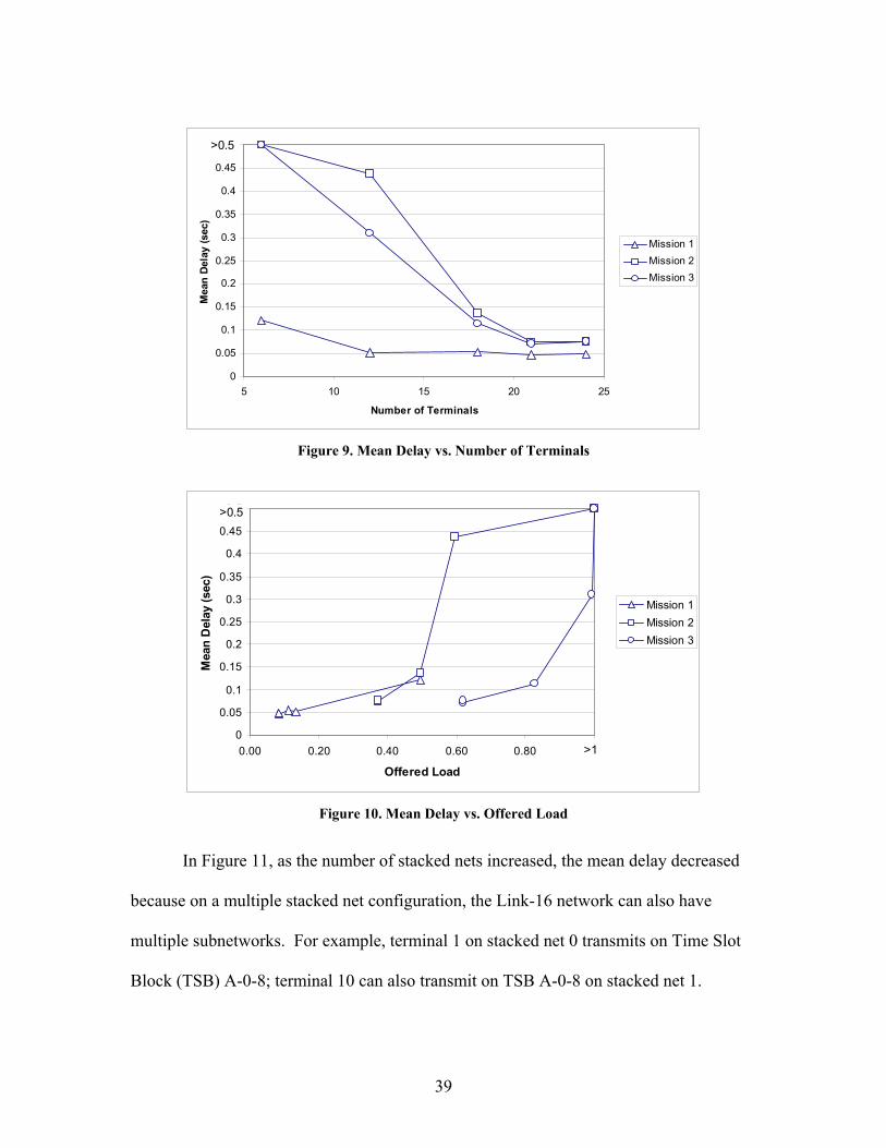
Figure 9 shows the mean delay of the Link-16 network decreases when the
number of terminals is increased. This is due to the dedicated access mode used for this
study; therefore, the number of terminals does not affect the mean delay as long as there
is sufficient number of time slots assigned to a terminal. The number of terminals used
does affect the number of time slots that can be assigned. For example, assuming that
there is only one stacked net available for use and 16 terminals required for the mission.
Since there are 128 time slots per second available, there are eight time slots per second
available for each terminals.
Figure 10 shows that the mean delay increases for each mission as the offered
load increases.
39
0
0.05
0.1
0.15
0.2
0.25
0.3
0.35
0.4
0.45
0.5
5 10 15 20 25
Number of Terminals
Mea
n De
lay
(sec
)
Mission 1Mission 2Mission 3
>0.5
Figure 9. Mean Delay vs. Number of Terminals
0
0.05
0.1
0.15
0.2
0.25
0.3
0.35
0.4
0.45
0.5
0.00 0.20 0.40 0.60 0.80 1.00
Offered Load
Mea
n D
elay
(sec
)
Mission 1Mission 2Mission 3
>0.5
>1
Figure 10. Mean Delay vs. Offered Load
In Figure 11, as the number of stacked nets increased, the mean delay decreased
because on a multiple stacked net configuration, the Link-16 network can also have
multiple subnetworks. For example, terminal 1 on stacked net 0 transmits on Time Slot
Block (TSB) A-0-8; terminal 10 can also transmit on TSB A-0-8 on stacked net 1.

40
Although terminal 10 is not able to receive transmission from terminal 1 and vice versa,
this poses a problem if terminal 1 and terminal 10 needs to communicate with each other.
0
0.05
0.1
0.15
0.2
0.25
0.3
0.35
0.4
0.45
0.5
1 2 3 4 5Number of Stacked Nets
Mea
n D
elay
(sec
)
Mission 1Mission 2Mission 3
>0.5
Figure 11. Mean Delay vs. Number of Stacked Nets
Figure 12 shows that the number of stacked nets does not affect the throughput of
the Link-16 network due to the independence between stacked nets.
0
10
20
30
40
50
60
1 2 3 4 5
# of Stacked Nets
Thro
ughp
ut (k
bps)
Mission 1Mission 2Mission 3
Figure 12. Throughput vs. Number of Stacked Nets
Network 2
Network 3

41
Also shown in Figure 13 is that the number of terminals does not affect the
throughput of the Link-16 network.
0
10
20
30
40
50
60
5 10 15 20 25
# of Terminals
Thro
ughp
ut (k
bps)
Mission 1Mission 2Mission 3
Figure 13. Throughput vs. Number of Terminals
4.4 Offered Load
As shown in Figure 14, the offered load for network 1 was above 100% when
used with missions 2 and 3. Since missions 2 and 3 overloaded the system, simulations
were not run under these conditions.
4.5 Analysis of Variance for Mean Delay
Table 5 summarizes ANOVA results for the mean delay of the Link-16 network
and shows that the network topology, mission, and interactions were all statistically
significant (F-computed value greater than F-table value) for a 90% confidence level. A
total of 94.2% variations were accounted for in this model. The network topology (Table
4) which accounts for 22% variation was primarily caused by the amount and allocation
of time slots. A 50% variation due to mission was caused by the increase in network

42
traffic on the network. The 22.2% variation due to interactions is shown in Table 7 and
discussed further in paragraph 4.6.
00.10.20.30.40.50.60.70.80.9
11.1
Msn 1 Msn 2 Msn 3
Network 1Network 2Network 3Network 4Network 5
>12.23 3.72
Figure 14. Offered Load
Table 5. ANOVA for Mean Delay
Component Sum of
Squares Percentage of Variation
Degrees of Freedom
Mean Square F-Computed F-Table
y 1.76 y.. 0.93 y-y.. 0.83 100.00 59 NW Topology 0.18 21.98 3 0.0607 61.01 2.20Mission 0.41 50.03 2 0.2072 208.27 2.42Interactions 0.18 22.22 6 0.0307 30.84 1.90Errors 0.05 5.76 48 0.0010
4.6 Confidence Interval for Effects and Interactions
Table 6 shows a 90% confidence interval for effects and indicates that the mission
has a significant effect on the network topology. Networks 3, 4, and 5 performed better
than network 2 because they were allocated more time slots. Network 3 had 576 (20%
increase) more time slots than network 2. Networks 4 and 5 had 1,728 (60% increase)
more time slots than network 2. Because of the low network traffic requirement and

43
allocation of more than the required number of time slots, mission 1 performed better
than the other missions.
Table 6. 90% Confidence Interval for Effects
Parameter Mean Effect Standard Deviation
90% Confidence
Confidence Interval
µ 0.1247 0.0041 0.0067 0.1180 0.1314 Network
2 0.1417 0.0071 0.0116 0.1301 0.1533 3 -0.0235 -0.0351 -0.0119 4 -0.0605 -0.0721 -0.0489 5 -0.0577 -0.0693 -0.0461
Missions 1 -0.0747 0.0058 0.0095 -0.0842 -0.0652 2 0.0565 0.0470 0.0660 3 0.0182 0.0087 0.0277
Interactions 0.0100 0.0164 See Table 7
Table 7 shows a 90% confidence interval for interactions and shows that all
interactions were significant except on networks 3, 4, and 5 when operating mission 3.
This result was caused by the increased network traffic of image transfer being allocated
to only one of the available stacked nets. Another cause is that networks 3, 4, and 5 were
already allocated a large number of time slots, averaging 96, 96, and 76.8 time slots per
second, respectively. Therefore, we can determine that for a large network traffic load
with a high average number of time slots per second, other configuration changes, i.e.
number of stacked nets in use or number of participants, does not affect the mean delay
of the system.
Table 7. 90% Confidence Interval for Interactions
Msn 1 Msn 2 Msn 3 Network 2 -0.1563 -0.1235 0.0984 0.1312 0.0087 0.0415 Network 3 0.0112 0.0441 -0.0382 -0.0054 -0.0222 0.0106 Network 4 0.0405 0.0733 -0.0625 -0.0297 -0.0272 0.0057 Network 5 0.0390 0.0718 -0.0632 -0.0304 -0.0250 0.0078

44
Figure 15 shows that for mission 1 operating under network 2 performed
statistically better than networks 3, 4, and 5. For the given configuration with low
network traffic and high allocation of time slots, the mean delay is already low.
Therefore, adding more than the required amount of time slots to an already low mean
delay does not decrease the mean delay.
-0.2
-0.15
-0.1
-0.05
0
0.05
0.1
Mea
n D
elay
(sec
)
NW 2
NW 3
NW 4 NW 5
Figure 15. Mission 1 Confidence Interval for Interactions
In Figure 16, networks 3, 4, and 5 statistically outperformed network 2 when
operating under mission 2. Because mission 2 requires a medium network traffic load,
more time slots are required to realize an improvement in mean delay.
As shown in Figure 17, increasing the number of time slots for a high network
traffic load does not improve the mean delay of the system.

45
-0.1
-0.05
0
0.05
0.1
0.15
Mea
n D
elay
(sec
) NW 2
NW 3NW 4 NW 5
Figure 16. Mission 2 Confidence Interval for Interactions
-0.04
-0.03
-0.02
-0.01
0
0.01
0.02
0.03
0.04
0.05
Mea
n D
elay
(sec
)
NW 2
NW 3
NW 4 NW 5
Figure 17. Mission 3 Confidence Interval for Interactions
4.7 Summary
This chapter discussed the result of the NETWARS simulation of the Link-16
network. First result discussed was the throughput of the system was equivalent to the
network load placed on the network due to the static assignment of time slots; therefore

46
contention of time slots was not an issue. Then, the mean delay of the Link-16 network
was discussed and the reason for the mean delay decrease. Then, the offered load of the
Link-16 network was shown. Then, the result of the ANOVA on the mean delay of the
system was shown with the network topology, mission, and interactions were all
significant using a 90% confidence level. Finally, the confidence interval of effects and
interactions were shown and discussed.

47
V. Conclusions and Future Work
5.1 Conclusions
As a result of the NETWARS simulations conducted for this study, the network
traffic load (mission) had significant effect on the Link-16 network topology. Based on
this result, it is determined that the selection of a network topology for a given mission is
critical to achieve mission success. Because Link-16 is a static network, addition of new
participants to the mission requires modification of the Link-16 design to include testing
and distribution. For a low network traffic mission, operating on a network having more
assigned time slots than required proves advantageous to the Link-16 network as shown
in Figure 15. However, as network traffic increases, adding more time slots to the
network does not decrease the mean delay of the Link-16 network.
The main parameter affecting the mean delay of the Link-16 network was the
number of time slots assigned to a participant. As the number of assigned time slots
increases, the mean delay of the system decreases. A fundamental constraint of the
Link-16 network is that it is limited to 128 time slots per second. Data throughput can be
increased by changing the data packing option to a higher data rate but doing so reduces
the anti-jam resistance of the Link-16 network. The highest achievable data rate from
one terminal when assigned all 128 time slots is 26,880 bps using the Packed-2 option.
In this case, this terminal has no time slots available to receive data from any other
terminals.
Overall, the Link-16 network is able to handle the increase in network traffic
when using multiple stacked nets. However, this decreases the ability of a participant to

48
communicate with the other participants. Using additional stacked nets alone on a Link-
16 network does not decrease the mean delay of the system. It does however allow the
system to have additional subnetworks which gives the system more time slots and a
corresponding decrease in mean delay. For example, consider the two stacked nets
operating in Figure 18. Assuming both stacked nets are using 128 time slots per second
each to minimize mean delay, they cannot communicate with each other because the
maximum number of time slots are already in use for their own subnetwork. For the two
stacked nets to communicate with each other, they need to decrease the number of time
slots of each stacked nets. For example, terminal 1 is assigned TSB A-0-8 to transmit on
stacked net 0, terminal 4 can be assigned TSB A-0-8 to receive on stacked net 0, but this
TSB is no longer available for use in stacked net 1. This is a problem if there are many
participants that need to communicate with each other.
Figure 18. Stacked Net Example
The Link-16 network architecture is difficult to manage due to the static
assignment of time slots designed by Link-16 network managers. There exists numerous
documents describing Link-16 network architectures designed for use in particular
1
2 3
4
6 5
Stacked Net 0
Stacked Net 1

49
missions or areas of operations. These documents are very specific on the Link-16
network design, e.g., what TSB is assigned to each participant. Any deviation from the
network design by unauthorized personnel is prohibited [CJC01b]. In addition, the static
assignment of time slots can be inefficient in that valuable time slots may go unused.
5.2 Future Work
Future research that could be examined on the Link-16 network would be the use
of other access modes, e.g., contention and time slot reallocation. Another candidate for
future work would be the combined use of all access modes. Since the static assignment
of time slots in a Link-16 network makes this architecture very difficult to manage, future
research could be done on the dynamic time slot allocation capability of the Link-16
network for all participants. Adding this capability on the network could alleviate the
network management difficulty faced today. Another area that could be researched
would involve finding a technique to increase the number of time slots per second beyond
the current limit.

50
Bibliography
[Air00] Air Combat Command, Public Affairs Office. Fact Sheet – E-3 Sentry (AWACS), http://www.af.mil/news/factsheets/E_3_Sentry__AWACS_ .html, July 2000.
[Air01] Air Combat Command, Public Affairs Office. Fact Sheet – RC-135V/W Rivet Joint, http://www.af.mil/news/factsheets/RC_135V_W_Rivet_ Joint.html, March 2001.
[AnB01] Anderson, R.H. and Baer, W., Potential Military Applications of Peer-to-Peer Computer Networks, Tech. Report DRR-2670-RC, RAND Corp., Santa Monica, CA, 2001.
[CJC01a] Chairman of the Joint Chiefs of Staff Instruction 3170.01B, http://www.dtic.mil/doctrine/jel/cjcsd/cjcsi/3170_01b.pdf, 15 April 2001.
[CJC01b] Chairman of the Joint Chiefs of Staff Instruction 6232.01B, http://www.dtic.mil/cjcs_directives/cdata/unlimit/6232_01.pdf, 16 March 2001.
[CRD01] Capstone Requirements Document, Global Information Grid, March 2001.
[ESC01] ESC/DIVJ, Link-16 Systems Integration Office. Air Force Concept of Link Employment, Version 2, 13 April 2001.
[Fed99] Federation of American Scientists, Military Analysis Network. EC-130E ABCCC, 27 March 1999.
[Goe02] Goebel, Greg. The E-8 Joint-STARS, 1 June 2002.
[JP01a] Joint Publication 3-0, Doctrine for Joint Operations, 10 September 2001.
[JP01b] Joint Publication 1-02, DoD Dictionary of Military and Associated Terms, 12 April 2001.
[JP02] Joint Publication 3-60, Joint Doctrine for Targeting, 17 January 2002.
[JP97] Joint Publication 3-03, Doctrine for Joint Interdiction Operations, 10 April 1997.
[Mar02] Marmelstein, Robert E. Force Templates – A Blueprint for Coalition Interaction within an Infosphere, May/June 2002.

51
[Nav03] Navy Communications Device Conversion Effort Verification and
Validation Report (Draft), Space and Naval Warfare Systems Center San Diego, 2 September 2003.
[Net03] NETWARS 2003-1 Final User Manual, Optimum Network Performance (OPNET) Technologies Inc., NETWARS Installation CD, 1 August 2003.
[Nor94] Northrop Grumman Corporation. Understanding Link-16, A Guidebook for New Users, Northrop Grumman Corporation, Information Technology Communication and Information Systems Division, April 1994.
[Pik99] Pike, John. Joint Surveillance Target Attack Radar System, http://www. globalsecurity.org/intell/systems/jstars.htm, 25 July 1999.
[USJ03] U.S. Joint Forces Command, Joint Interoperability and Integration. Information Exchange Requirements http://www.teao.saic.com/jfcom/ier/ splash.htm, Science Applications International Corporation, 2003.
[Whi01] White, B. E., Layered Communications Architecture for the Global Grid, The MITRE Corporation, supported by the U.S. Air Force Electronic System Center under contract number F19628-99-C-0001, March 2001.

REPORT DOCUMENTATION PAGE Form Approved OMB No. 074-0188
The public reporting burden for this collection of information is estimated to average 1 hour per response, including the time for reviewing instructions, searching existing data sources, gathering and maintaining the data needed, and completing and reviewing the collection of information. Send comments regarding this burden estimate or any other aspect of the collection of information, including suggestions for reducing this burden to Department of Defense, Washington Headquarters Services, Directorate for Information Operations and Reports (0704-0188), 1215 Jefferson Davis Highway, Suite 1204, Arlington, VA 22202-4302. Respondents should be aware that notwithstanding any other provision of law, no person shall be subject to an penalty for failing to comply with a collection of information if it does not display a currently valid OMB control number. PLEASE DO NOT RETURN YOUR FORM TO THE ABOVE ADDRESS. 1. REPORT DATE (DD-MM-YYYY)
March 2004 2. REPORT TYPE
Master’s Thesis
3. DATES COVERED (From – To) Mar 2003 – Mar 2004
5a. CONTRACT NUMBER
5b. GRANT NUMBER
4. TITLE AND SUBTITLE NETWARS BASED STUDY OF A JOINT STARS LINK-16 NETWORK
5c. PROGRAM ELEMENT NUMBER
5d. PROJECT NUMBER 5e. TASK NUMBER
6. AUTHOR(S) Cruz, Charlie, I., Master Sergeant, USAF 5f. WORK UNIT NUMBER
7. PERFORMING ORGANIZATION NAMES(S) AND ADDRESS(S) Air Force Institute of Technology Graduate School of Engineering and Management (AFIT/EN) 2950 P Street, Building 640 WPAFB OH 45433-7765
8. PERFORMING ORGANIZATION REPORT NUMBER AFIT/GCS/ENG/04-06
10. SPONSOR/MONITOR’S ACRONYM(S)
9. SPONSORING/MONITORING AGENCY NAME(S) AND ADDRESS(ES) AFCA/ITAI Attn: Mr. Dean Benson 203 West Losey St. Rm 1109 DSN: 785-4539 Scott AFB IL 62225-5222 e-mail: [email protected]
11. SPONSOR/MONITOR’S REPORT NUMBER(S)
12. DISTRIBUTION/AVAILABILITY STATEMENT APPROVED FOR PUBLIC RELEASE; DISTRIBUTION UNLIMITED.
13. SUPPLEMENTARY NOTES 14. ABSTRACT Both secure and anti-jam resistant, the Link-16 is the primary communications channel used by the Joint Surveillance Target Attack Radar System (Joint STARS) for the exchange of real-time tactical data among various ground, air, and sea platforms of the United States of America and North Atlantic Treaty Organization forces. This research explored the effect of increasing network traffic for imagery transfer to the mean delay when operating under different network topologies. Using Network Warfare Simulation (NETWARS), three different missions were simulated to run on five network topologies having a different number of participants, different assigned time slots, and stacked nets. As a result, this study determined that the Link-16 network is able to handle the increase in network traffic, from 30 kilobits per second to 50 kilobits per second, when using multiple stacked net configurations while assigning an adequate number of time slots. However, because each participant is limited to 128 time slots per second, the increased network traffic limits the communication ability of other participants. 15. SUBJECT TERMS Communications Network, Networks, Data Links, Data Transmission Systems, Frequency Agility, Frequency Hopping
16. SECURITY CLASSIFICATION OF: 19a. NAME OF RESPONSIBLE PERSON Rusty O. Baldwin, Maj, USAF (ENG)
a. REPORT
U
b. ABSTRACT
U
c. THIS PAGE
U
17. LIMITATION OF ABSTRACT
UU
18. NUMBER OF PAGES
62
19b. TELEPHONE NUMBER (Include area code) (937) 255-6565, ext 4445; e-mail: [email protected]
Standard Form 298 (Rev. 8-98) Prescribed by ANSI Std. Z39-18