Embed Size (px)
Citation preview

AIR FORCE HANDBOOK 10-222, Volume 6 1 April 1999
DEPARTMENT OF THE AIR FORCE
GUIDE TO BARE BASEFACILITY ERECTION

Report Documentation Page Form ApprovedOMB No. 0704-0188
Public reporting burden for the collection of information is estimated to average 1 hour per response, including the time for reviewing instructions, searching existing data sources, gathering andmaintaining the data needed, and completing and reviewing the collection of information. Send comments regarding this burden estimate or any other aspect of this collection of information,including suggestions for reducing this burden, to Washington Headquarters Services, Directorate for Information Operations and Reports, 1215 Jefferson Davis Highway, Suite 1204, ArlingtonVA 22202-4302. Respondents should be aware that notwithstanding any other provision of law, no person shall be subject to a penalty for failing to comply with a collection of information if itdoes not display a currently valid OMB control number.
1. REPORT DATE 01 APR 1999
2. REPORT TYPE N/A
3. DATES COVERED -
4. TITLE AND SUBTITLE Guide To Bare Base Facility Erection - Air Force Handbook 10-222,Volume 6
5a. CONTRACT NUMBER
5b. GRANT NUMBER
5c. PROGRAM ELEMENT NUMBER
6. AUTHOR(S) 5d. PROJECT NUMBER
5e. TASK NUMBER
5f. WORK UNIT NUMBER
7. PERFORMING ORGANIZATION NAME(S) AND ADDRESS(ES) Secretary Of The Air Force Washington, DC
8. PERFORMING ORGANIZATIONREPORT NUMBER
9. SPONSORING/MONITORING AGENCY NAME(S) AND ADDRESS(ES) 10. SPONSOR/MONITOR’S ACRONYM(S)
11. SPONSOR/MONITOR’S REPORT NUMBER(S)
12. DISTRIBUTION/AVAILABILITY STATEMENT Approved for public release, distribution unlimited
13. SUPPLEMENTARY NOTES
14. ABSTRACT
15. SUBJECT TERMS
16. SECURITY CLASSIFICATION OF: 17. LIMITATION OF ABSTRACT
UU
18. NUMBEROF PAGES
91
19a. NAME OFRESPONSIBLE PERSON
a. REPORT unclassified
b. ABSTRACT unclassified
c. THIS PAGE unclassified
Standard Form 298 (Rev. 8-98) Prescribed by ANSI Std Z39-18

BY ORDER OF THE AIR FORCE HANDBOOK 10-222, VOLUME 6SECRETARY OF THE AIR FORCE 1 APRIL 1999
Operations
GUIDE TO BARE BASE FACILITY ERECTION
NOTICE: This publication is available digitally on the AFDPO/PPP WWWsite at http://afpubs.hq.af.mil. If you lack access, contact your PublishingDistribution Office (PDO).OPR: HQ AFCESA/CEXR (Major Gregory A. Cummings)Certified by: HQ AFCESA/CEX (Colonel Bruce F. Mc Connell)Pages 90/Distribution F
This handbook is designed to assist you to erect and strike the most commontypes of Harvest Falcon bare base facilities. These include the TEMPER tent,expandable shelter container and general purpose shelter. The handbookdiscusses site selection and layout, major components of each facility,erection procedures and disassembly procedures. When coupled withinformation contained in AFPAM 10-219, Vol. 5, Bare Base ConceptualPlanning Guide, applicable technical orders, and instruction received at SilverFlag training sites, personnel should be capable of effectively setting up abare base facility complex.
PageINTRODUCTION ......................................................................................5TEMPER TENT .........................................................................................7EXPANDABLE SHELTER CONTAINER ............................................... 40GENERAL PURPOSE SHELTER ............................................................ 51
Figures1. TEMPER Tent..................................................................................72. TEMPER Tent Fabric Components ...................................................83. TEMPER Tent Frame Components ...................................................94. Ridge and Eave Extenders .............................................................. 10

AFH 10-222 Volume 6 1 April 1999 2
5. Fabric Plenums............................................................................... 106. Vestibule ........................................................................................ 117. Rowley Box.................................................................................... 128. Ship/Store Containers ..................................................................... 129. Ridge Joint Assembly ..................................................................... 1410. Header Assembly............................................................................ 1411. Purlin-to-Arch Connection.............................................................. 1512. Diagonal Brace-to-Arch Connection ............................................... 1613. Rotation of Tab Handle to Lock Tab Into Arch................................ 1614. Locking of Tab Handle ................................................................... 1715. Assembled TEMPER Tent Frame ................................................... 1716. Large Grommet Placed Over Ridge Joint Spindle............................ 1817. Typical Lacing Pattern.................................................................... 1918. Closing of Velcro Weather Flap ...................................................... 2019. Placement of End Wall Peak Grommet............................................ 2120. Installation of Ridge Extenders ....................................................... 2121. Lacing of Tent Fly .......................................................................... 2222. Placement of Tent Fly Over Ridge Extenders .................................. 2223. Installation of Eave Extenders......................................................... 2324. Placement of Tent Fly Over Eave Extenders.................................... 2425. Attachment of Guy Rope to Tent Fly............................................... 2426. Attachment of Guy Rope to Eave And Ridge Extenders .................. 2527. Raising of Tent Frame Assembly .................................................... 2628. Eave Joint Assembly....................................................................... 2629. Securing Purlin Flaps...................................................................... 2730. Sod Cloth Placement....................................................................... 2831. Guy Ropes...................................................................................... 2832. Flooring Section Installation ........................................................... 2933. Electrical Cable Routing ................................................................. 3034. Light Support Strap Assemblies ...................................................... 3135. Overhead Liner Connections........................................................... 3136. Plenum Connection to Ventilation Sleeve........................................ 3237. Electrical Distribution Box Stand.................................................... 3338. Installation of Light Fixtures........................................................... 34

AFH 10-222 Volume 6 1 April 1999 3
39. Vestibule Frame Assembly ............................................................. 3640. Vestibule Frame Installation ........................................................... 3641. Vestibule Final Assembly ............................................................... 3742. Expandable Shelter Container ......................................................... 4143. Installation of Corner Jacks............................................................. 4244. Leveling Center Section.................................................................. 4245. Raising of Roof Panel ..................................................................... 4346. Safety Cable Attachment ................................................................ 4447. Raising of End Wall........................................................................ 4448. Positioning of Swing-out Side Walls ............................................... 4549. Final Positioning of Expanded Section ............................................ 4550. Anchor Cable Layout...................................................................... 4751. Environmental Control Unit Installation.......................................... 4852. General Purpose Shelter.................................................................. 5153. General Purpose Shelter Shipping Container ................................... 5254. Basepads, Beams and Panels........................................................... 5355. End Wall Components .................................................................... 5456. Layout Plan for GP Shelter ............................................................. 5657. Component Layout Diagram ........................................................... 5758. Basepad Layout .............................................................................. 5959. Basepad Anchoring......................................................................... 6060. Anchor Cable Tensioning ............................................................... 6261. Panel-to-Arch Beam Connection ..................................................... 6362. Beam-to-Beam Pin Connection ....................................................... 6463. Pinning of Panel to Basepads .......................................................... 6564. Erection Track Placement .............................................................. 6665. Placement of Panel Sections Prior to Erection ................................. 6766. Winch Hoist and Harness Assembly................................................ 6867. Breached Panel Section................................................................... 6968. GP Shelter Windows....................................................................... 6969. GP Shelter Mechanical Connection Panel........................................ 7070. Bare Base Environmental Control Unit Attached to GP Shelter ....... 7071. Spacer Bar Attachment ................................................................... 7172. Interior Electrical System Component Positioning........................... 7373. Lighting Fixture Cable Run............................................................. 74

AFH 10-222 Volume 6 1 April 1999 4
74. Interior Electrical System Schematic Diagram................................. 7575. Ridge Flashing Installation.............................................................. 7676. Column Attachment to Arch Beam ................................................ 7777. Installation of Header...................................................................... 7778. L2/LU-2 Column Connection.......................................................... 7879. Upper Panel Section Placement....................................................... 7980. Door Assembly............................................................................... 8081. Door Hinge Mounting Bolts and Column Mounting Inserts ............. 8182. Door Flashing Attachment .............................................................. 8283. Attaching End Wall Flashing to End Wall Panels ............................ 8284. Arch Counterflashing Attachment ................................................... 8485. Installation of Ground Skirt Flashing............................................... 8586. Pulling Shear Stakes ....................................................................... 90

AFH 10-222 Volume 6 1 April 1999 5
INTRODUCTION
GUIDE TO BARE BASE FACILITY ERECTION
PURPOSE OF HANDBOOK
This handbook addresses the procedures used to erect and disassemble theHarvest Falcon TEMPER tent, expandable shelter container (ESC) andgeneral purpose (GP) shelter. It is meant to be used by civil engineeringpersonnel in setting up their quarters and work centers and assisting otherbase personnel in establishing their shop areas. Users of this booklet areassumed to have a basic knowledge of bare base assets and their function—readers without this fundamental knowledge should review the applicabletechnical orders; AFPAM 10-219, Volume 5, Bare Base Conceptual PlanningGuide; AFH 10-222, Volume 1, Guide To Bare Base Development; and AFH10-222, Volume 2, Guide To Bare Base Assets.
Information contained in this handbook is drawn from the following sources:
TO 35E5-6-1, Tent, Extendable, Modular
TO 35E4-94-1, Expandable Shelter/Container
TO 35E4-132-1, General Purpose Shelter
The three facility types discussed in this handbook comprise the majority ofmobile facilities contained in the four Harvest Falcon deployment sets(housekeeping, industrial operations, initial flightline support, follow-onflightline operations). TEMPER tents are by far the most numerous withapproximately 425 of them used to support a typical three aircraft squadronbeddown operation. Next most plentiful is the ESC with about 30 units,followed by the GP Shelter with approximately 25 facilities.

AFH 10-222 Volume 6 1 April 1999 6
Fortunately, the TEMPER tent, while being the most populous, is the easiestto erect. Although all base personnel are supposed to be able to erect thisshelter, be prepared to provide assistance at least in a supervisory mode. Inall likelihood; however, you will have to erect some of these tents for otherpeople. Plan on having to erect all ESCs and GP shelters as they arrive. Fewfolks other than engineers have access to these buildings in peacetime fortraining purposes. If you are lucky, some aircraft maintenance people whohave had experience with these assets will be part of your deployment andcan help out. Remember to practice proper safety procedures during theerection of all facilities—use gloves, safety shoes, etc., to protect yourself andthose around you.

AFH 10-222 Volume 6 1 April 1999 7
TEMPER TENT
Characteristics.The TEMPER tent (figure 1) is a modular soft-walled shelter consistingmainly of a synthetic material fabric supported by an aluminum framestructure. Its modular construction allows many different facility sizes. Thebasic tent module measures 8’ by 20’. These modules are connected togetherto form various configurations, the most common being the 32’ by 20’billeting version. This basic billeting unit weighs about 1200 pounds.TEMPER tents are used for several other functions besides billeting. Theseinclude latrines, administrative offices, shops, kitchens, shower/shave unitsand medical facilities. TEMPER tents are meant to be used in desert, tropicaland temperate climates and come in both desert tan and forest green colors.Utility support for these tents includes electrical service for lighting andconvenience outlets and provisions for heating and cooling using the barebase environmental control unit or the new field deployable environmentalcontrol unit.
Figure 1. TEMPER Tent.

AFH 10-222 Volume 6 1 April 1999 8
Major Components.The TEMPER tent has many major components. Only the most commonones will be addressed in this handbook. You should consult the TEMPERtent technical order for expanded details.
Fabric. The major fabric components include the window section, endsection, door section and fly (figure 2). Both the window and door sectionsare 8-feet wide, enough to cover one section of tent frame. The end sectioncontains door and window openings and spans the 20’ dimension of the tent.The fly covers the roof of the tent and provides insulating support.
Figure 2. TEMPER Tent Fabric Components.
Frame. The TEMPER tent metal frame (figure 3) consists of arches,ridge joints, headers and purlins that are pinned together to form a rigidstructure.
Ridge Extenders (figure 4). Ridge extenders are attached to the ridgepoints of the frame structure to hold up the fly.

AFH 10-222 Volume 6 1 April 1999 9
Eave Extenders (figure 4). These items are attached to the eave of theframe structure to hold up the fly.
Liner. The tent liner, installed inside the tent, provides insulation valueand helps keep the inside of the tent clean.
Fabric Plenums (figure 5). These fabric ducts are hung inside the tent tochannel heated and cooled air from the environmental control unit.
Vestibule (figure 6). The vestibule is a covered entranceway into a tentor a covered passageway between tents.
Electrical Control Box. This electrical box is mounted inside the tentand connects the external power supply to the internal lights and outlets.
Figure 3. TEMPER Tent Frame Components.

AFH 10-222 Volume 6 1 April 1999 10
Figure 4. Ridge and Eave Extenders.
Figure 5. Fabric Plenums.

AFH 10-222 Volume 6 1 April 1999 11
Figure 6. Vestibule.
Site Preparation.Site preparation for the TEMPER tent is not an extensive requirement. Thearea the tent is to be placed upon should be relatively level, well drained, andfree from debris such as stones, roots and underbrush. Obviously, the tentsshould not be placed in a location subject to jet blast or high winds.
Component Layout.TEMPER tents are packaged for shipment in two types of containers. TheRowley box (figure 7) holds one tent and the Ship/Store Container (figure 8)contains four. As you unpack the containers, make a quick inventory of thecontents to ensure all major items are there. Place the components along theedge of the tent site in the order they will be used. Normally the componentswill be laid out as follows:
Line up each frame bundle along the site edge.
Place the window sections between frame sections.
Place end walls at each end of tent.

AFH 10-222 Volume 6 1 April 1999 12
Figure 7. Rowley Box
Figure 8. Ship/Store Container.

AFH 10-222 Volume 6 1 April 1999 13
Place fly at every other window section.
Place intermediate liners next to window sections
Place end section liners next to end sections.
Frame Assembly.Assembly of the frame is a straightforward process once the basic steps arelearned. The arches are assembled first and then they are joined together withpurlins. Take care handling the arches during assembly to ensure they do nottwist. Also be careful around the ridge and eave hinges—pinched hands andfingers are common if one is not paying attention. Assemble the arches asfollows:
Remove an arch from one of the frame bundles and make sure thelocking pins are hanging free.
Place the arch on the ground and spread out the center section so you canwork at the ridge joint.
Align the holes in the arch with those in the ridge joint and insert thelocking pin (figure 9).
Swing out the two legs of the arch and then obtain a header. Place thelegs of the arch between the flanges on each end of the header and insertlocking pins (figure 10). Slant end of header faces up.
Repeat the above procedures for the rest of the arches you will requirefor the size tent you are making.
Obtain purlins. They are 8-feet long with tabs on each end. Specialpurlins are used at entrance doors—they have a flat plate (doorsill) in themiddle.

AFH 10-222 Volume 6 1 April 1999 14
Figure 9. Ridge Joint Assembly.
Figure 10. Header Assembly.

AFH 10-222 Volume 6 1 April 1999 15
Hold two arches upright and parallel. Insert tab of purlin into the boss ofthe ridge joint (figure 11).
Figure 11. Purlin-to-Arch Connection.
Rotate purlin 90 degrees so that tab locks in the boss of the ridge joint.
Take the diagonal brace attached to the purlin and rotate it toward thearch.
Insert the tab at the free end of the brace into the slot in the arch (figure12).
Rotate tab handle on the brace 90 degrees to lock tab into the arch slot(figure 13).
Push tab handle down towards arch until it is locked in place (figure 14).
It takes five purlins to connect two arches (one at the ridge, two at the eaves,two at the bases). Continue installing purlins until all arches have beenconnected. Ridge purlins are installed with every other diagonal bracerotated to the left and right sides of the ridge. This provides added structural

AFH 10-222 Volume 6 1 April 1999 16
rigidity. The braces on the eave purlins are installed pointing toward the baseof the tent. When your frame is all assembled, it should resemble figure 15.Do not raise the frame structure at this time; this action will be accomplishedafter fabric components are attached.
Figure 12. Diagonal Brace to-Arch Connection.
Figure 13. Rotation of Tab Handle to Lock Tab Into Arch.

AFH 10-222 Volume 6 1 April 1999 17
Figure 14. Locking of Tab Handle.
Figure 15. Assembled TEMPER Tent Frame.
Fabric CoveringThis phase of TEMPER tent erection involves placing the window and doorsections on the frame, attaching the end walls and installing the fly. It willtake a minimum of two people to accomplish the fabric covering tasks. Makesure door sections, if used, are placed where door purlins have been installed

AFH 10-222 Volume 6 1 April 1999 18
and that the stovepipe openings in all sections are all on the same side of theframe.
With one person on each side of a window section, locate the largegrommets at the center of each side of the section.
Carry the section to the center of the frame and place the grommets overthe spindles at the ridge joints (figure 16).
Repeat the previous two steps for each roof section to be installed. Ifyou know where the environmental control unit for the tent will belocated, ensure the duct ports in the tent are appropriately installed nearthe unit’s position.
Once all the window and door sections are in place on the frame, lacing of thesections can begin. Only one side of the tent roof is laced initially; thesecond side is laced after the fly is partially installed. To make the lacingeasier, place the large eave grommet of one of sections out of each pair beinglaced over its eave spindle. This tautens one side of the section pairs. Lacingis begun at the ridge joint and progresses down to the eave line.
Figure 16. Large Grommet Placed Over Ridge Joint Spindle.

AFH 10-222 Volume 6 1 April 1999 19
Insert the first and second laces through the first and second grommets.
Run second lace up through the loop in the first lace and pull second lacetight (figure 17).
Figure 17. Typical Lacing Pattern.
Insert third lace through third grommet and through loop in second laceand pull tight.
Close the Velcro weather flap as lacing progresses (figure 18).
Continue lacing in the same manner until the reaching the next-to-lastlace from the eave. Run the next-to-last lace through the loop in the lastlace. Pull the next-to-last lace back toward the ridge and tie it off with ahalf-hitch knot.
Make sure the large eave grommet of the second section of the pair isplaced over the eave spindle. Do not lace below the eave line at thistime.

AFH 10-222 Volume 6 1 April 1999 20
Continue lacing sections on the one side together until all completed.
End wall sections are installed next.
Figure 18. Closing of Velcro Weather Flap.
Find and place the large grommet of the end wall peak over the ridgespindle (figure 19) and the eave grommet of the side with laces over theeave spindle.
Lace both sides of the end wall to their adjacent respective windowsections and tie off with half hitches. Install second end wall in samefashion.
Once end walls are in place, the tent fly is installed.
Place ridge extenders over all ridge spindles and insert locking pins(figure 20).
Lay out tent fly on the ground adjacent to the side of the tent and lacesections together. Start lacing at the ridge grommets and work towardthe eaves (figure 21). Close weather flap as you go.

AFH 10-222 Volume 6 1 April 1999 21
Once fly is completely laced, roll it from both sides toward the middlewhere the ridge grommets are located. Make sure vent stack ports in thefly are on the same side of the tent as the ports in the tent roof if you areplanning to use internal tent heaters.
Figure 19. Placement of End Wall Peak Grommet.
Figure 20. Installation of Ridge Extenders.

AFH 10-222 Volume 6 1 April 1999 22
With an individual at each center grommet, pick the rolled fly up andcarry it to the ridge line of the tent. This will have to be done on the roofside of the tent that has not been laced up yet.
Figure 21. Lacing of Tent Fly.
Place the center grommets of the fly over the ridge extenders and installthe hitch clip pins to secure the fly (figure 22).
Figure 22. Placement of Tent Fly Over Ridge Extenders.

AFH 10-222 Volume 6 1 April 1999 23
Unroll the fly down the sides of the roof to the eaves. The roof side ofthe tent that has not yet been laced should be laced now and weather flapclosed as the fly is being unrolled.
Make sure eave grommets of all window sections are over eave spindles.Install eave extenders over eave spindles (brace of eave extender pointstoward ridge). Insert hitch clip pins to secure eave extender to eavespindle (figure 23).
Place eave grommets of the fly over eave extender spindles and securethe fly in place with hitch pins (figure 24).
Attach guy ropes to the tent fly at each eave extender spindle locationand both ridge extender spindle locations on the end walls. The guy ropeis threaded through one side of a tent slip, then through the webbingloops of the fly and back through the other side of the tent slip (figure25). Knot the end of the rope so it doesn’t slide back through the tentslip.
Figure 23. Installation of Eave Extenders.

AFH 10-222 Volume 6 1 April 1999 24
Figure 24. Placement of Tent Fly Over Eave Extenders.
Figure 25. Attachment of Guy Rope to Tent Fly.
Additional guy ropes are attached to eave and end wall ridge extenders attheir bases. The guy rope is threaded through a tent slip, placed throughthe brace and around the pole of each extender and back through theother side of the tent slip (figure 26). Again, the rope is knotted off at thetent slip.

AFH 10-222 Volume 6 1 April 1999 25
Figure 26. Attachment of Guy Ropes to Eave and Ridge Extenders.
Frame ErectionWhen the tent fly is in place, one side of the tent frame is lifted into position.Any desired internal components are then installed before raising the secondside of the tent.
Roll up the unlaced sidewalls of the tent and place them between the roofand tent fly. Ensure guy ropes are also out of the way.
Ensure the locking pin at each eave joint is hanging freely and lockingholes in the arches are clear of foreign materials.
With two people at each eave joint, lift the frame to shoulder height. Pullin the leg of the arch and place the weight of the tent assembly on thearch leg (figure 27). Be careful not to twist or bend frame componentswhen lifting the tent assembly.
Align the holes of the eave joint and arch leg and insert the locking pin(figure 28).

AFH 10-222 Volume 6 1 April 1999 26
Figure 27. Raising of Tent Frame Assembly.
Figure 28. Eave Joint Assembly.

AFH 10-222 Volume 6 1 April 1999 27
Secure the roof fabric to the eave purlins using the Velcro connections onthe purlin flap (figure 29).
Figure 29. Securing Purlin Flaps.
Install internal components as desired (selected component installationwill be discussed in the next section).
Raise the second side of the tent using the same procedures as used onthe first side.
Roll down the tent walls, lace up all the sides and close the weather sealflaps.
Use 12-inch metal steel pins to stake down frame footings at the base ofeach arch. Stake one side of the tent first, then adjust the other side toensure it is a maximum of 20’4” at the base. If you have installed theflooring, stake the side of the tent that the flooring is tied to first.
Attach bottom purlin flaps to the base purlins.
Pull sod cloth under the base purlins and end walls (figure 30).

AFH 10-222 Volume 6 1 April 1999 28
Install 24-inch wooden stakes 10 feet from sides and ends of tentopposite the eave extenders. Normally stakes are slanted toward the tent.
Connect guy rope from the eave extender to bottom notch of the stake;rope from tent fly goes to the top notch of the stake (figure 31).
Figure 30. Sod Cloth Placement.
Figure 31. Guy Ropes.
AFH 10-222 Volume 6 1 April 1999 29
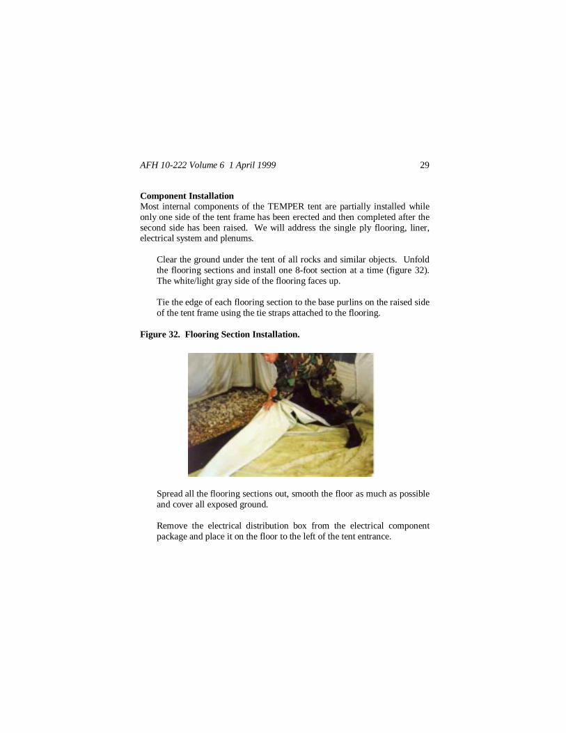
Component InstallationMost internal components of the TEMPER tent are partially installed whileonly one side of the tent frame has been erected and then completed after thesecond side has been raised. We will address the single ply flooring, liner,electrical system and plenums.
Clear the ground under the tent of all rocks and similar objects. Unfoldthe flooring sections and install one 8-foot section at a time (figure 32).The white/light gray side of the flooring faces up.
Tie the edge of each flooring section to the base purlins on the raised sideof the tent frame using the tie straps attached to the flooring.
Figure 32. Flooring Section Installation.
Spread all the flooring sections out, smooth the floor as much as possibleand cover all exposed ground.
Remove the electrical distribution box from the electrical componentpackage and place it on the floor to the left of the tent entrance.

AFH 10-222 Volume 6 1 April 1999 30
Route the power supply cables leading out of the box so that they will bebetween the liner and end wall. Wrap them once around the end wallarch header to relieve strain on the cables.
Route supply cables for outlets down the end wall arch and out on theeave purlins. Convenience outlet lines will be plugged into these onceliner is up. Route supply cables for overhead lighting along the end wallarch header down to the header-arch connection (figure 33). Overheadlighting cables will connect to these supply lines once liner is up.
Install light support strap assemblies between arches near the arch-headerconnection points (figure 34). Let the white straps on the support strapassemblies hang freely.
Bring a tent liner section inside the tent and unfold it.
Figure 33. Electrical Cable Routing.

AFH 10-222 Volume 6 1 April 1999 31
Figure 34. Light Support Strap Assemblies.
Locate the three support straps on the liner, push one end of each straparound the ridge purlin and connect it to its respective other end (figure35).
Figure 35. Overhead Liner Connections.

AFH 10-222 Volume 6 1 April 1999 32
Tie center tie tapes to headers, side tie tapes to adjacent frame members.Use bow knots.
Install the remaining liner sections to include end walls. Fasten linerstogether using the Velcro strips along their edges.
Obtain end wall or sidewall plenum as appropriate. Attach intake end ofplenum to ventilation sleeve in the tent wall (figure 36). Attach theplenum duct to arch headers using the ties along the sides of the plenum.
Attach plenums together using the Velcro fasteners and connect them totent frame headers until required length is reached. Install plenum capon last section.
Raise the second side of the tent frame using the same procedures asdescribed earlier.
Lace the remaining end and sidewall sections and close weather flaps.
Figure 36. Plenum Connection to Ventilation Sleeve.

AFH 10-222 Volume 6 1 April 1999 33
Attach tent fabric purlin flaps to base purlins and pull sod cloth under thebase.
Spread out floor sections, connect them together using the Velcrofasteners and tie them to the base purlins.
Place electrical distribution box stand between the liner and end wall tentfabric adjacent to where the electrical box was initially placed.
Extend the stand until its upper flange meets the header, then insert thehitch pin near the base of the stand to lock the stand in place (figure 37).Ensure the stand is solid.
Hang the distribution box on the distribution box stand plate by insertingthe bolts on the box into the keyhole slots on the plate.
Figure 37. Electrical Distribution Box Stand.
Obtain light fixture and wrap light hanger straps around it at each endinside of the rubber end caps (figure 38). Secure straps using theirVelcro fasteners. Ensure male plug end of fixture is facing the electricaldistribution box.

AFH 10-222 Volume 6 1 April 1999 34
Install all remaining light fixtures on both sides of the tent and plug themtogether. Plug fixture strings into supply lines from the distribution box.Also attach convenience outlet strings to their supply lines. Route cablesas necessary through the liner.
Figure 38. Installation of Light Fixtures.
The lighting system described in the preceding paragraphs is more commonlyused in specialized Harvest Falcon facilities such as the air transportablehospital. Most other TEMPER tents used by Air Force personnel will havean incandescent lighting system. This system consists of a junction streamer,two light streamers (3 lights each), and two outlet streamers. The junctionstreamer is plugged into the power distribution panel (part of the HarvestFalcon electrical system) located outside of the tent and run under the outsidefabric into the tent (a qualified electrician should make the connection). Theoutlet and light streamers are plugged into a receptacle box at the end of thejunction streamer. The lights have hooks attached to them enabling them tobe hung from the tent frame structure and slipped through the tent liner at thevelcro seams. The light strings also have receptacles and plugs at their endsallowing them to be connected together. Normally one light streamer is

AFH 10-222 Volume 6 1 April 1999 35
installed on each side of the tent air plenum. All cabling is installed betweenthe tent and its liner as much as possible.
Vestibule AssemblyThe vestibule assembly is used either as an entranceway to a TEMPER tent oras a connecting passage between two tents. While a vestibule is useful inhelping maintain cleanliness of the tent and providing a weather barrier at anentrance, a TEMPER tent does not need one to function properly. Avestibule can be connected to both an end wall or side wall door opening. Itis installed as follows:
Unroll the vestibule adapter around the door opening and unfold andspread out the vestibule fabric itself.
Find and align the center grommets in the adapter and the vestibulefabric. Lace the vestibule to the adapter starting at the ridge and workingdown to eaves. Tie off at the eave using a half hitch.
Assemble the three vestibule frames by inserting the frame legs into thevestibule frame headers (figure 39). Insert locking pins to secure thelegs.
Take one frame, place it under the adapter/vestibule connection andinsert the spindles on the frame through the three grommets (ridge andtwo eave).
Insert hitch pins in spindle and close weather flap.
Insert second frame at midpoint of vestibule fabric; place spindlesthrough grommet and insert hitch pins (figure 40).
Lean total assembly back against the tent side and install third frame investibule fabric.

AFH 10-222 Volume 6 1 April 1999 36
Figure 39. Vestibule Frame Assembly.
Figure 40. Vestibule Frame Installation.

AFH 10-222 Volume 6 1 April 1999 37
Extend vestibule out completely and attach guy ropes to the spindles atthe eaves of the third frame section and stake them to the ground (figure41).
Fasten the tie tapes inside the vestibule around the frames and finishlacing the vestibule to the adapter and closing the weather seals.
Install 12-inch metal pins in base plates of all vestibule frames to anchorframes in place.
Figure 41. Vestibule Final Assembly.
Striking ProceduresCare must be taken in disassembling the tent so as not to damage it in anyway or otherwise make it unserviceable for future deployments. As items areremoved during tear down, clean them as thoroughly as possible. Do notpack any components wet. Before starting disassembly, have the electricalservice to the tent disconnected from the local power source and gather allpacking boxes. Procedures for striking the tent are as follows:
Close all windows and doors and release tension on guy ropes.

AFH 10-222 Volume 6 1 April 1999 38
Untie vestibule tie tapes and pull steel pins from vestibule frame baseplates.
Collapse vestibule against the tent and remove hitch pins from vestibuleframe spindles.
Remove the three frames from vestibule fabric and disassemble them.
Unlace vestibule from adapter, fold and pack vestibule fabric.
Remove guy ropes from stakes and pull all stakes and metal tent pins.
Remove and pack lighting fixtures.
Untie floor and liner tie tapes from base purlins and disconnect all basepurlin flaps.
Take electrical distribution box down and remove the distribution boxstand.
Unhook all outside fabric laces up to the eave level and untie liner fromsides of the frame.
Fold up fabric sections from the sides of the tent and placed them underthe tent fly.
Take away electrical outlets.
With personnel at each arch, pull the locking pins at the eave connectionsand lower tent to the ground.
Unhook and remove plenums and liners.
Remove electrical distribution box and light support strap assemblies.

AFH 10-222 Volume 6 1 April 1999 39
Unfasten, fold and remove all floors.
Disconnect eave purlin flaps.
Remove hitch clip pins and fly from eave extenders.
Remove eave extenders and unlace all roof sections.
Remove hitch clip pin from ridge extender, remove and fold fly anddisconnect ridge extenders from frame.
Remove end walls and all roof (sidewall) sections.
Disconnect all diagonal frame braces and fold them up.
Rotate and remove purlins.
Lay frames on their sides and remove locking pins in header flanges.
Remove ridge locking pins.
Fold up arch frame sections and strap together.

AFH 10-222 Volume 6 1 April 1999 40
EXPANDABLE SHELTER CONTAINER (ESC)
CharacteristicsThe expandable shelter container (figure 42) is a hard-walled building used tosupport functions that require a more substantial, weather-tight facility suchas aircraft maintenance shops, command posts and laboratories. The ESCunfolds from a packaged shipping container (center section) to an expandedshelter mode. The foldout roof panels are hinged to the center section roof;the folded floors are hinged to the center structure floor. End walls arehinged to the foldout floors, and swing-out walls for the sides are hinged tothe center structure sidewalls. The structure is leveled and supported by eightjacks. Double doors are installed in one end wall of the center section and apersonnel door is in the other end. When folded, the ESC dimensions areapproximately 13 feet long, 8 feet wide and 8 feet high. When expanded, itssize is approximately 13 feet long, 21.5 feet wide and 8 feet high. You willneed a forklift to move the facility to its site; it weighs a little over 2 tons.The ESC is heated and cooled using a bare base environmental control unit(ECU) or the new field deployable environmental control unit (FDECU).
Site PreparationSite preparation for the ESC is relatively minimal. The location must havegood drainage and enough maneuvering room for easy forklift movement.Slope of the area should be such that not more than an 18-inch change inelevation over the footprint area of the facility is encountered. Clear loosematerials and undergrowth from the area that will be under the building onceit is expanded. Most ESCs will have to have immediate vehicle access sincethey are shops. Keep this requirement in mind and don’t forget to allowspace for the external ECU. Look for firm ground conditions since the entireweight of the building rests on the eight support jacks; soft ground could leadto uneven settlement and eventual facility damage. An option for the softground situation is to place plywood or lumber under the jacks forstabilization.

AFH 10-222 Volume 6 1 April 1999 41
Figure 42. Expandable Shelter Container.
Expanding The ShelterExpanding the shelter entails unfolding and connecting the roof, floor andwalls of each side of the shelter and installing the eight leveling jacks.Several people are required to erect this facility (minimum of 6) since someof the pieces that will be moved weigh approximately 250 pounds. Sheltererection activity begins with the center section of the ESC.
Remove jacks from their storage location inside the ESC and install onejack at each corner of the center section (figure 43)
Raise shelter enough so that all parts of the base are 3-6 inches off theground. To avoid overloading the jacks or twisting the structure, rotateboth jacks on one side simultaneously.
Place level on floor of center section parallel to the 13’ dimension. Raiseand level the low end of the center section first using both jacks on thesame side simultaneously.

AFH 10-222 Volume 6 1 April 1999 42
Place level on the rim of the center section parallel to the 8’ dimension.Raise and level the low end using both jacks on the same sidesimultaneously (figure 44).
Figure 43. Installation of Corner Jacks.
Figure 44. Leveling Center Section.

AFH 10-222 Volume 6 1 April 1999 43
Check for final level in all directions. Repeat the previous two stepsagain as necessary.
Unlatch the roof from the center section of the structure. Unpin theadjustable roof support struts and extend the inner tube to the point thatthree holes are visible below the outer tabs and pin in place. Raise theroof, being careful not to bind the support strut swivel (figure 45). If astrut is not making firm contact with the ground due to surfaceunevenness, simply extend the pole by one or more holes.
Rotate locking plate 180 degrees, and attach safety cable to floor section.Lower floor section to horizontal position (figure 46). If floor does notlower properly, it may be necessary to extend the roof support struts byone or more holes.
Raise end wall to vertical position (figure 47), then hold it in place andswing sidewalls out (figure 48).
Figure 45. Raising of Roof Panel.

AFH 10-222 Volume 6 1 April 1999 44
Figure 46. Safety Cable Attachment.
Figure 47. Raising of End Wall.

AFH 10-222 Volume 6 1 April 1999 45
Figure 48. Positioning of Swing-out SideWalls.
Latch floor to sidewalls, then latch end wall to sidewalls.
Install jacks at each corner of the expanded section.
Lower roof onto end wall and sidewalls with support struts and latch roofto walls. Place support struts back into stowed position (figure 49).
Figure 49. Final Positioning of Expanded Section.

AFH 10-222 Volume 6 1 April 1999 46
Remove safety cables from floor and stow them back in the centersection.
Repeat the above steps for the other side of the shelter.
AnchoringTo provide additional stability to the shelter and reduce the effects of windloading, the ESC is anchored to the ground in several places. The anchors,driving rod and driving head are included with the ESC, but you will have toobtain a sledgehammer, crescent wrench and jack (such as an automobilejack) to perform the anchoring task. The anchors with cables attached aredriven approximately three feet into the ground, then set using the jack.
The center section requires eight anchors, two near each corner. One of thecorner anchors is placed so that the anchor cable goes straight out from thetie-down ring on the center section pallet and heads down at a 30-degreeangle. The second anchor is placed so that the anchor cable will be 30degrees out from the wall and heading down at a 45-degree angle (figure 50).The cable from this second anchor connects through a hole in the centersection underframe.
Anchors are also installed for the expanded sections of the ESC; two anchorsper section, one at each corner (figure 50). These anchors are installed suchthat the cables from the building to the anchor will be 30 degrees out from theshelter end wall and heading down at a 45-degree angle. The cables areattached to tie down rings, which are screwed into the bottom of the end wallsection floor.
Cables are connected to the ESC using cable clamps once the facility isleveled and expanded.

AFH 10-222 Volume 6 1 April 1999 47
Figure 50. Anchor Cable Layout.
Electrical/Mechanical ConnectionsThe ESC is prewired and requires little effort to connect to supportingutilities. For electrical connections:
Turn off all circuit breakers.
Remove overhead light fixtures from their stowed position in the centersection and install two on the ceiling of each of the expanded sections.
Assemble exterior light fixture and mount adjacent to personnel door.
Plug exterior light cable into the J3 receptacle on the exterior powerpanel.

AFH 10-222 Volume 6 1 April 1999 48
Remove outlets from their stowed position and mount them on the wallsof the expanded sections.
For ECU installation (figure 51):
Remove solid panels from air inlet and outlet openings.
Install louvered air inlet panel in the top opening.
Figure 51. Environmental Control Unit Installation.
Install unlouvered air outlet panel in the bottom opening.
Connect flexible ducts from the ECU to the appropriate openings. Ifdesired, the ventilation fans may be removed and replaced with the solidpanels from the air inlet and outlet openings.Connect power cable from the ECU to receptacle J2 on the exteriorpower panel.
Connect power-input cable from the electrical distribution system toreceptacle J1 on the exterior power panel. A qualified electrician shouldcomplete this connection.

AFH 10-222 Volume 6 1 April 1999 49
Striking ProceduresStriking procedures for the ESC are meant to disassemble the facility andplace it back into shipping configuration. Throughout the disassembly andpacking process, remember to thoroughly clean the various components sothat damage is not caused to the building and problems are not encounteredwith customs officials at the ports.
Turn all circuit breakers off.
Disconnect all cabling at the external power panel.
Remove and stow the external lighting fixture.
If ventilation fans were removed during assembly, replace them at thistime. Disconnect the ECU flexible ducting and replace air inlet andoutlet panels with solid panels.
Relocate internal overhead lighting and utility outlet fixtures to stowedpositions. To prevent damage to the structure when stowing the outletfixtures, ensure the flush side of the fixtures is turned toward the hingedside of the wall.
Disconnect all tie-downs, remove tie-down rings and pull anchors.
Unpin roof support struts from stowed position on one of the expandedsections and place them in position to support the roof panel.
Unwrap the safety cables and attach between upper center structure andthe floor.
Remove the jacks from the corners of the section being folded and stowthe jacks in the center section.

AFH 10-222 Volume 6 1 April 1999 50
Disconnect side walls and end wall from roof section and raise roof usingthe roof support struts sufficiently to allow clearance for folding upwalls.
Disconnect end wall and floor from sidewalls and rest end wall againstthe support struts.
Rotate right sidewall, then left side walls into stowed position.
Fold end wall down to the floor and then raise floor to folded position.Use the safety cable to help support the floor in increments as it is raised.
Detach safety cable from floor and place in stowed position.
Partially lower the roof section and pin support struts in stowed position.
Completely lower roof section and latch it into place on the centersection.
Repeat the appropriate steps above to close the other expanded section ofthe ESC.
Remove the four jacks supporting the center section and stow theminside the center section.

AFH 10-222 Volume 6 1 April 1999 51
GENERAL PURPOSE SHELTER
CharacteristicsThe General Purpose (GP) Shelter (figure 52) is an air transportable, hard-walled facility used primarily for equipment and aircraft maintenance shops.The entire facility is shipped inside a single container (figure 53). Thiscontainer when filled weighs approximately 11,000 pounds; therefore, youwill obviously need a forklift to transport the GP shelter to its erection site.The building occupies a 31-foot by 48-foot area and provides about 1400square feet of unobstructed floor space once erected. It will takeapproximately 90-120 man-hours to assemble. Crew size is normally abouteight people. The basic shelter consists of five arches, two end walls and anelectrical system. Provisions are also made for connection of twoenvironmental control units. Each of the arches consists of six beam panels.Each beam panel consists of two arch beams and
Figure 52. General Purpose Shelter.

AFH 10-222 Volume 6 1 April 1999 52
Figure 53. General Purpose Shelter Shipping Container.
one panel. The arches are self-supporting and are secured to basepads, whichare anchored to the ground. The end walls consist of column-supportedpanels and truck doors. The electrical system includes interior lighting,exterior lighting and outlets. Several types of fabric flashing for the variousjoints in the facility are provided to preclude weather problems.
Major ComponentsTypes A, B, and C Basepads (figure 54). Three types of aluminumbasepads are used to anchor the shelter to the ground. Type C basepadssecure the end wall columns to the ground. Type B basepads are used atthe corners of the shelter to secure the corner arch beams. Type Abasepads are used along the sides of the building to hold the arches inplace.
Types A, B, C, D and E Arch Beams (figure 54). Five types ofaluminum arch beams are used to provide the structural rigidity for theGP shelter. Types B and C arch beams attach to the basepads whiletypes A, D and E form the overhead arch members.

AFH 10-222 Volume 6 1 April 1999 53
Panels (figure 54). There are 38 panels required for typical GP sheltererection; 30 solid, 4 breached (ECU connection panels) and 4 specialty(end wall upper panels).
End Walls (figure 55). In addition to the solid and specialty panelsmentioned above, the end walls require truck door entrances, supportcolumns and headers. R1 and L1 columns support the ends of the endwall and R2/RU2 and L2/LU2 columns support the truck doors. Thealuminum header spans the truck door columns and is also attached tothe overhead end arch beams.
Figure 54. Basepads, Beams and Panels.

AFH 10-222 Volume 6 1 April 1999 54
Figure 55. End Wall Components.
Shelter Flashing. Shelter joints are sealed against the weather by ridgeflashing, arch counterflashing, ground skirt flashing, end wall flashing,jamb flashing, panel-to-panel flashing and panel-to-beam flashing. Theridge flashing is installed along the ridge of the shelter, one section foreach arch. The arch counterflashing covers the arch-to-arch joints.Ground skirt flashing seals the base of the facility. End wall flashingprotects the joint between the top of the end wall and the end arch of theshelter. Jamb flashing is used to seal the connection of the doorassemblies to the end wall panels. Panel-to-panel and panel-to-beamflashing seal the joints between the panel and beam structural members.
Electrical System. The electrical system includes a distribution panel,eight junction boxes, eight interior fixtures, two exterior light assembliesand two extension cables.
Two standard sized GP shelters can be erected end to end, with no endwalls in the middle section, to form one larger facility.

AFH 10-222 Volume 6 1 April 1999 55
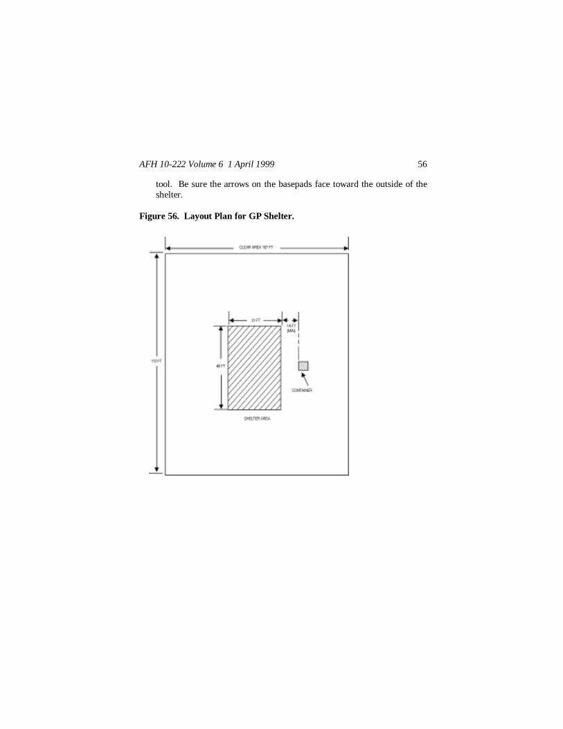
Site PreparationYou should strive to site the GP shelter in an area that has good accessibility,drainage, and vehicle maneuvering space. Figure 56 illustrates a typicallayout. Grade the site as necessary to provide a relatively level surface.Choose a site that is firm enough to support fork lift traffic initially andconstant cargo vehicle traffic once the facility is erected. Check figure 56 forlocation of the shipping container—you don’t want to have it in the waywhen you start to construct the building nor do you want it too far away soyou have to carry building components a great distance.
Component LayoutYour first step is to unpack the shipping container and place the sheltercomponents around the outside of the shelter area near where they will beused during the erection of the shelter. You should totally remove the doorsof the container, loosen retaining straps as needed and place the cargo nettingback over the top of the container to keep it out of the way. Remove thebuilding components and place them around the shelter area—use thediagram in figure 57 as a location guide. Make sure you have enoughpersonnel available to safely move the heavier items, some weigh almost 300pounds. Once the shipping box is emptied of building components put thestraps, netting and dunnage back into the container. Additionally, after thebuilding is set up place any empty packing boxes back into the container.You will need all these items when you take down and repack the facility inthe future.
Basepad Layout And AnchoringLaying out the basepads for the GP shelter is a critical first step in sheltererection. These plates must be accurately arranged or the shelter cannot beerected properly. The steps involve aligning the A, B and C basepads,staking the basepads in place, and tying them down with ground anchors.The general procedures for these tasks are as follows:
Obtain basepad layout tool (two special cables used to form a righttriangle) and attach type B basepads to each of the three posts on the
AFH 10-222 Volume 6 1 April 1999 56
tool. Be sure the arrows on the basepads face toward the outside of theshelter.
Figure 56. Layout Plan for GP Shelter.

AFH 10-222 Volume 6 1 April 1999 57
Figure 57. Component Layout Diagram.

AFH 10-222 Volume 6 1 April 1999 58
Extend the type B basepads to the three corner locations, ensuring layouttool cables are correctly seated in the slots on top of the posts (figure 58).If you want to have the shelter oriented in a specific direction, now is thetime to do it by adjusting the orientation of the legs of the cable triangle,e.g., paralleling one of the legs with an adjacent road surface. Keep thecables taut.
Stake the corner basepad (the one at the right angle of the triangle) downwith four shear stakes. Drive the stakes only halfway.
Pull the layout tool cables tight to final locate the remaining twobasepads and stake each of these with four shear stakes driven onlyhalfway.
Recheck the position of the basepads to ensure they are in the locationyou desire. If so, drive all the shear stakes in completely.
Locate four type A basepads under the side cable (the 48’ leg). Align thebasepad lugs with the sleeves of the side cable (figure 58). Ensurearrows on the basepads point outward.
Place two type C basepads under the end cable (the 31’ leg). Align thebasepad lugs with the sleeves of the end cable. Two additional type Cbasepads will be installed later during end wall erection for a total of fourtype Cs on each end of the shelter.
Using shear stakes, completely stake down the A basepads (6 stakes) andC basepads (3 stakes).
Reposition the basepad layout tool to allow layout of basepads on othertwo sides of the shelter. Leave the 57’ cable in place (the diagonal cable)move the other layout cable.
Attach a type B basepad to the single available post, stretch the cablestaut and position the basepad. Stake it in place with four shear stakes.

AFH 10-222 Volume 6 1 April 1999 59
Figure 58. Basepad Layout.

AFH 10-222 Volume 6 1 April 1999 60
Position the remaining four type A and two type C basepads and stake inplace. Remove layout tool and place it back in its storage container.
Place four anchors at each type A and B basepad. Drive anchors at eachcorner of each basepad at a 30-degree angle (figure 59). Anchors shouldbe driven to depth of about 5 feet.
Set anchors using the 5’ drive rod, cable puller, and fulcrum bar (figure59). The cable puller is attached to the anchor cable and then attached tothe drive rod. Set one end of the drive rod in the fulcrum bar and pull upso that the anchor sets. The anchor cable will have to be pulled about 6”for the anchor to set.
Figure 59. Basepad Anchoring.

AFH 10-222 Volume 6 1 April 1999 61
Thread anchor cables through the most direct holes in the heads of theshear stakes of the basepads directly opposite each other on both sides ofthe shelter (figure 60).
Loop anchor cables near shear stakes and attach wire rope clamps buttighten only the wire rope clamps on the outside loops (figure 60). Notethat the two cables on each basepad are interconnected--the inside cableis run through the outside cable loop.
Form a second loop in the end of one of the inside anchor cables andattach the clevis of the erection harness to it.
Attach the cable puller to the inside cable at the opposite basepad. Installwinch hoist between erection harness and cable puller (figure 60).
Use the winch hoist to tighten the anchor cables and secure inside cablewire rope clamps.
Repeat the above cable tightening steps for the remaining sets of cablepairs on all basepads.
Arch Assembly and ErectionArches are erected individually beginning at either end of the shelter. Eacharch is comprised of six beam panels connected together by pins and hinges.The arches are raised using a winch and track assembly and pinned at the“keystone area” and basepads. Erection of the shelter arches is begun at theright hand corner as you face the end wall.
Place a type B arch beam mounting end near the type B basepad withspacer bars facing out and flashing fastener strips facing up. Place a typeC arch beam mounting end near the type A basepad with spacer barsfacing out and flashing fastener strips facing up.

AFH 10-222 Volume 6 1 April 1999 62
Figure 60. Anchor Cable Tensioning.

AFH 10-222 Volume 6 1 April 1999 63
Place a solid panel between the two arch beams on the arch beam supportlips (figure 61). Side with exterior flashing attached faces up; the whiteside of the panel faces down. The panel edge with the flashing retainerstrip is placed such that the flashing from the next arch panel up can beattached.
Secure the panel to the arch beams by rotating and engaging the latchassemblies. Listen for an audible click to indicate the latch is fullyengaged.
Attach the panel-to-beam flashing to the flashing fastener strips on bothbeams.
Assemble panel #2 in the same fashion as panel #1 using one type E archbeam, one type D arch beam and a solid panel section.Pin the top hinge of the type D arch beam of panel #2 to the type C archbeam of panel #1 (figure 62).
Figure 61. Panel-to-Arch Beam Connection.

AFH 10-222 Volume 6 1 April 1999 64
Figure 62. Beam-to-Beam Pin Connection.
Pin the top hinge of the type E arch beam of panel #2 to the type B archbeam of panel #1.
Lift the panel assemblies to an inverted “V” position and pin the lowerhinges of the types D and E arch beams to the links in the types C and Barch beams.
Position the basepad mounting ends of the type B and C arch beams onthe first panel assembled on the type A and B basepads and pin into place(figure 63).
Fasten panel-to-panel flashing between the second panel assembled andthe first panel.
Assemble a third panel section using two type A arch beams and onesolid panel.

AFH 10-222 Volume 6 1 April 1999 65
Figure 63. Pinning of Panel to Basepads.
Pin the third panel assembly to the second at both the upper and lowerhinges of the arch beams.
Fasten the panel-to-beam flashing of the third panel and the panel-to-panel flashing between the third and second panels.
Assemble a fourth panel section using a type B arch beam, a type C archbeam and a solid panel.
Assemble a fifth panel section using a type D arch beam, a type E archbeam and a solid panel.
Pin the fourth panel assembly to the fifth at both the upper and lowerhinges of the arch beams.
Fasten the panel-to-beam flashing of both panels and the panel-to-panelflashing between the fourth and fifth panels.

AFH 10-222 Volume 6 1 April 1999 66
Assemble a sixth panel section using two type A arch beams and a solidpanel.
Lift one end of panel section six and the free end of panel section threeand pin the top hinges of panel section six to the top hinges of panelsection three. Allow the free end of panel six to remain on the ground.
Place panel sections 4 and 5 adjacent to panel section six so that the tophinges of sections 5 and 6 can be pinned.
Install erection tracks on basepads A and B on the left-hand side as youface the end wall. Panel section 4 will eventually connect to thesebasepads. The tracks are pinned in place and positioned such that theyextend outward from the basepads (figure 64).
Figure 64. Erection Track Placement.
Lift the arch assembly sufficiently high enough so that the lower hingesof panel sections 5 and 6 can be pinned. As the panels are lifted forpinning, guide the arch beam ends of panel four into the erection tracks(figure 65).

AFH 10-222 Volume 6 1 April 1999 67
Figure 65. Placement of Panel Sections Prior to Erection.
Assemble erection harness to winch hoist and secure harness to archbeams (figure 66).
For protection against cable breakage, place an end wall solid sectionresting on two end wall columns over the winch hoist cable (figure 66).
Operate the winch hoist; the unpinned end of the arch will be drawninward. After the unpinned end has been drawn in about a foot, lift thecenter point of the arch until the arch is about 5 feet off the ground.
Continue operating the winch hoist until the ends of the arch beams ofpanel section 4 slide into the basepads.
Unpin the erection tracks and slide them out of the way. Use the anchordriving rod as a lever to raise the panel 4 arch beams sufficiently to alignthe beam mounting holes with the basepad lugs. Once the basepad lugsand beam mounting holes are aligned, pin the arch beams to thebasepads. To prevent damage to the panels, lift only on the aluminumbeams.

AFH 10-222 Volume 6 1 April 1999 68
Figure 66. Winch Hoist and Harness Assembly.
Pin the lower hinges of panel sections 3 and 6 together and removeerection tracks and winch hoist assembly.
The remaining arches of the GP shelter are erected similarly to the first one.These adjacent arches share type A basepads. Arches 2 and 4 differ slightlyin that they have breached panels installed as panel sections 1 and 4. Thesebreached panels (figure 67) have openings for windows and mechanicalsystem connections. Both the windows (figure 68) and mechanicalconnection panels (figure 69) insert into the side wall panel openings and aresecured in place using latches tightened by thumbscrews. Figure 70illustrates the typical connection of the bare base ECU to the shelter walls.

AFH 10-222 Volume 6 1 April 1999 69
Figure 67. Breached Panel Section.
Figure 68. GP Shelter Windows.

AFH 10-222 Volume 6 1 April 1999 70
Figure 69. GP Shelter Mechanical Connection Panel.
Figure 70. Bare Base Environmental Control Unit Attached to GPShelter.

AFH 10-222 Volume 6 1 April 1999 71
As adjacent arches are erected, they are joined together with spacer bars toprovide structural rigidity. Two spacer bars are built into each type A, B andC arch beam. Their installation is straightforward.
Starting at the bottom arch beam (work from outside of the shelter),unpin and swing the lowest spacer away from its attached arch beam andloosen the hand knob on the spacer.
Extend the spacer bar until it meets with the angle bracket on theadjacent arch beam, align the holes and pin it in place (figure 71). Handtighten the hand knob.
Use installed spacer bars as a ladder to reach higher spacer bars. Asspacer bars are installed, check panel-to-panel and panel-to-beamflashings for correct attachment.
Figure 71. Spacer Bar Attachment.
Interior Electrical System InstallationThe interior electrical system for the GP shelter consists of a powerdistribution panel, several junction boxes, overhead lighting fixtures and

AFH 10-222 Volume 6 1 April 1999 72
associated cabling. The types of lighting fixture may vary depending on themodel of the shelter but both are incandescent therefore the installationprinciples are similar. Basic installation is as follows:
Find the boxes containing the electrical components and unpack them.Place the electrical components adjacent to their installation locations(figure 72). Note that there are several types of junction boxes. In somecases you may have to assemble the lighting fixtures.
Run the light hanger wire rope up and over the first spacer bar of panelsection 3 and connect the loop end of the wire rope to the hook on the topof the lighting fixture.
Run the cable from the light fixture up and over all the spacer bars inpanel section 2 (figure 73).
Install the remaining lights in the same manner at their respectivelocations.
Attach the power distribution panel to the adjacent arch beams on thepanel 1 sections of the first and second arches erected—see figure 72.
Attach junction box A1 to the fourth spacer bar from the ground betweenthe panel 1 sections of the first and second arches erected.
Install the seven remaining junction boxes making sure the junction boxlocations shown in figure 72 are followed (see figure 74 for electricalschematic).
Connect the electrical cables between the lights, junction boxes andpower distribution panel. Connect the extension cables for the outsidelights to the J3 connector of junction boxes A1 and A5 but leave themcoiled on the ground for now.

AFH 10-222 Volume 6 1 April 1999 73
Figure 72. Interior Electrical System Component Positioning.

AFH 10-222 Volume 6 1 April 1999 74
Figure 73. Lighting Fixture Cable Run.
Ridge Flashing InstallationOnce the spacer bars are positioned and interior electrical work is completed,ridge flashing is installed. Five flashing strips are used; one at each of thejoints of panel sections 3 and 6 at the ridge of the shelter. The strips areunrolled over the joints and the rubber seals on the flashing are inserted intothe retainers on the panels (figure 75).
End Wall ErectionErection of the end walls consists of column erection, panel installation, doorinstallation and flashing installation. Both end walls are erected in anidentical manner. Installation of the RU-2 and LU-2 columns and placementof the type B clamps can also be done prior to raising the end arches ifdesired. This option makes the end wall erection a little easier since the archbeams are easily accessible and stepladders won’t be needed.

AFH 10-222 Volume 6 1 April 1999 75
Figure 74. Interior Electrical System Schematic Diagram.

AFH 10-222 Volume 6 1 April 1999 76
Figure 75. Ridge Flashing Installation.
Column Erection
Obtain the end wall column locator bar and columns RU-2 and LU-2.
Lay the column locator bar on the lower flange of the arch beam of panelsection 3 butted up against end of the hinge.
Attach column RU-2 to the arch beam (figure 76). Snug the clamp onthe end of the column up to the end of the locator bar and tighten clamphand knob. Knob should be facing in toward the inside of the shelter.
Attach column LU-2 to lower flange of panel section 6 in a mannersimilar to installation of column RU-2.
Join the two halves of the header together with the “T” pin and pin theheader unit between columns RU-2 and LU-2 (figure 77).

AFH 10-222 Volume 6 1 April 1999 77
Secure the header to panel section 6 arch beam using the headersupport clamp (figure 77).
Figure 76. Column Attachment to Arch Beam.
Figure 77. Installation of Header.

AFH 10-222 Volume 6 1 April 1999 78
Panel Installation
Place end wall columns L1 and L2 on the ground about 7 feet apart withlatches facing in and flashing fastener strips up.
Place a panel section between the columns and fasten latches with latchwrench.
Attach panel flashing to columns.
Build second end wall panel section using columns R1 and R2.
Lift the L1/L2 panel section into place, pinning column L2 to columnLU-2 (figure 78).
Figure 78. L2/LU-2 Column Connection.
Attach column L1 to panel section 5 arch beam using the column clampassembly.

AFH 10-222 Volume 6 1 April 1999 79
After placing a type C basepad under column L1, remove the outside pinof the L2/LU-2 column connection and swing panel section inward awayfrom the basepad.
Stake basepad in place.
Swing panel back to vertical position, pin locking bars of L1 and L2columns to basepads and replace pin in L2/LU-2 connection.
Install the R1/R2 panel section in the right side of the end wall.
Mount two type B clamp assemblies on the lower flange of both panelsection 2 and 5 arch beams.
Position the upper left side panel in place (flashing on outside) and latchto column LU-2. Position and tighten the two type B clamp assemblies(figure 79).
Figure 79. Upper Panel Section Placement.

AFH 10-222 Volume 6 1 April 1999 80
Secure panel-to-panel and panel-to-column flashing.
Install upper right side panel in same manner as left side.
Door Installation
Assemble left door by inserting splice bars and mounting bracket ofupper door panel into the channel and mounting bracket of lower doorpanel (figure 80). Put right door together in a similar manner.
Obtain door positioning tool and install it on lower end of column R2.
Place hinged side of right door on positioning tool and turn adjustingknob until hinge mounting bolts are lined up with column R2 mountinginserts (figure 81).
Figure 80. Door Assembly.
AFH 10-222 Volume 6 1 April 1999 81
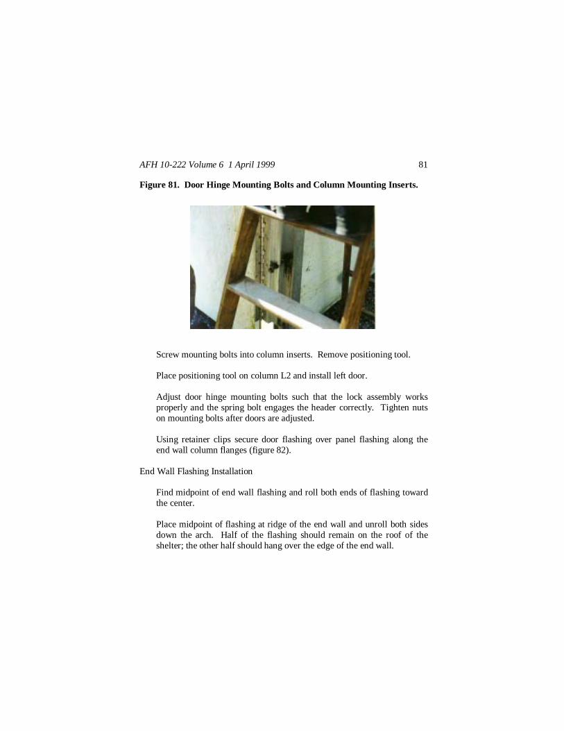
Figure 81. Door Hinge Mounting Bolts and Column Mounting Inserts.
Screw mounting bolts into column inserts. Remove positioning tool.
Place positioning tool on column L2 and install left door.
Adjust door hinge mounting bolts such that the lock assembly worksproperly and the spring bolt engages the header correctly. Tighten nutson mounting bolts after doors are adjusted.
Using retainer clips secure door flashing over panel flashing along theend wall column flanges (figure 82).
End Wall Flashing Installation
Find midpoint of end wall flashing and roll both ends of flashing towardthe center.
Place midpoint of flashing at ridge of the end wall and unroll both sidesdown the arch. Half of the flashing should remain on the roof of theshelter; the other half should hang over the edge of the end wall.

AFH 10-222 Volume 6 1 April 1999 82
Figure 82. Door Flashing Attachment.
Starting at the ridge, work down both sides of the shelter pressing therubber edge of the flashing into the end wall flashing channel (figure 83).
Figure 83. Attaching End Wall Flashing to End Wall Panels.

AFH 10-222 Volume 6 1 April 1999 83
Once columns R1 and L1 are reached attach flashing to inner flange ofthese columns using retainer clips. Leave bottom two feet of flashingloose at this time.
When the securing of the end wall edge of the flashing is complete, startback at the ridge to secure the other side of the flashing strip. Attach theflashing to the upper flange of the arch beams from the ridge down thearch to ground level. Leave the bottom two feet of flashing loose at thistime.
Exterior Electrical System InstallationThe exterior electrical system simply consists of exterior lighting at both endsof the shelter. The light assembly cable is plugged into junction box A1 (orA5 depending on which end you’re working on) and run up the end wallflashing to the ridge of the shelter. The light fixture is attached to the shelterat the ridge of the end wall using a clamp assembly.
Arch Counterflashing InstallationArch counterflashing is one continuous strip for each arch joint. Thisflashing is installed over each arch joint after all interior and exteriorelectrical work has been completed and ridge and end wall flashings havebeen installed.
Find the midpoint of the counterflashing and roll both ends of theflashing toward the center. The midpoint of the counterflashing isnotched.
Starting with the midpoint at the ridge of the shelter, unroll thecounterflashing down the arch joint.
Secure counterflashing to arch beams with retainer clips (figure 84).Leave bottom two feet of counterflashing loose at this time.

AFH 10-222 Volume 6 1 April 1999 84
Electrical Power ConnectionsConnection of the power cable to the shelter must be accomplished by aqualified electrician. The 208/120 volt source line is normally run from anoutside power distribution panel to the J1 receptacle on the shelter’sinternally mounted distribution panel.
Installation of Ground Skirt FlashingGround skirt flashing is attached basically to keep water and wind blown dustfrom entering the facility. These flashing pieces are attached to the bottomsof the end wall panels and arch panel sections 1 and 4.
Separate the two types of flashing (end wall and sidewall).
Attach the panel-to-panel flashing of the end/side panels to the groundskirt by pressing the rubber seal of the panel-to-panel flashing into theretainer channel on the ground skirt (figure 85).
Figure 84. Arch Counterflashing Attachment.

AFH 10-222 Volume 6 1 April 1999 85
Figure 85. Installation of Ground Skirt Flashing.
Attach the lower ends of the arch counterflashing (the two feet offlashing left loose earlier) to the arch beams. At the arch joints makesure the ground skirt is under both the arch counterflashing and panel-to-beam flashing.
Anchor down the ground skirt flashing with sandbags or other suitableweights.
In some GP shelter configurations you may receive a membrane floor—referto the technical order for its installation. Other flooring you may want toconsider include plywood or AM-2 matting or in light loading situations, thenew light-weight flooring, as existing ground loading conditions dictate.Once your shelter is up be sure all tools, dunnage, packing boxes and packingstraps are placed back into the shelter’s shipping container.
Striking ProceduresStriking of the GP shelter is essentially the reverse of the erection procedures.Remember to clean the various components as you disassemble them, notonly to prolong the life of the facility but also to ensure customs clearance

AFH 10-222 Volume 6 1 April 1999 86
goes smoothly. Refer to the technical order for the detailed procedures onfolding components and packing the shipping container. Before starting totear down the shelter, have a qualified electrician disconnect the electricalservice. The 49th Materiel Maintenance Group’s large structures unit typecode XFBJ2 four-person team can provide technical experts to assist witherection, striking, or packing the GP shelter.
Removal of Ground Skirt Flashing
Remove sandbags from around ground skirt.
Separate ground skirt flashing from arch and end wall panel flashingsand arch counterflashing.
Stack, roll up and secure (with ropes) ground skirt flashings.
Removal of End Wall Flashing
Remove exterior light assemblies and clamp assemblies from end wallridges.
Disconnect exterior light cabling from distribution box and put lights andcables aside for packing later.
Remove retainer clips that secure the end wall flashing to the arch beamsand end wall columns.
Separate end wall flashing from retainers in end wall panels.
Take down, fold and secure end wall flashing.
End Wall Disassembly
Separate door flashings from end wall columns.

AFH 10-222 Volume 6 1 April 1999 87
Unscrew hinge mounting bolts of right door from end wall column.
Lower door to the ground and separate the upper and lower doorsections.
Take down left hand door in similar fashion as right hand door.
Remove upper end wall panels by disconnecting flashing, removing thetype B clamps and opening the panel latches. Take down both right andleft upper panels.
Loosen the clamp at the top of column R1 and unpin the R2/RU-2column connection and the bases of both columns R1 and R2. Removethe lower right end wall panel.
Remove the lower left end wall panel in a similar manner. Put both theright and left panels aside for disassembly later.
Disconnect the header clamp assembly from the arch beam.
Unpin and take down the header assembly. Separate the two headerpieces.
Unclamp and remove the RU-2 and LU-2 columns (this also can be donelater when the end arches are lowered).
Take down the end wall at the other end of the shelter using the sameprocedures.
Removal of Environmental Control Unit/Window Panels
Disconnect environmental control unit (ECU) ductwork.
Loosen thumbscrews and turn latches.
AFH 10-222 Volume 6 1 April 1999 88
Remove window/ECU panels.
Tighten thumbscrews.
Removal of Ridge Flashing and Arch Counterflashing
Remove retainer clips holding counterflashing to arch beams.
Take down, roll up and secure arch counterflashing (roll both endstoward middle).
Separate ridge flashing seal from retainer strips on panels.
Take down and stack ridge flashing.
Removal of Interior Electrical System
Disconnect all overhead lights from their respective junction boxes.
Take down overhead lights.
Remove lights and cables from shelter and set aside for later packing.
Disconnect and remove cabling between all junction boxes and thedistribution panel.
Take down and remove the power distribution panel from shelter.
Take down and remove all junction boxes from shelter.
Disassembly of Arches
Attach erection harness to arch and install safety guard (end wall panel)over cable.

AFH 10-222 Volume 6 1 April 1999 89
Starting at the top of the arch disconnect all spacer bars and pin them totheir arch beams. Detach all panel-to-panel flashing.Using the anchor driving rod as a lever, lift panel section 4 enough topermit removal of pins holding panel to the basepad. Remove both pins.
Position and pin erection track to basepad.
Lift center of arch and remove pins in the lower hinges of the connectionof panels 3 and 6.
Ensure panel section 4 arch beam ends are properly in the erection track.Pull outward on panel 4 as the winch releases the cable. The center ofthe arch will lower. Eventually pressure will not be required outward onpanel 4 and gravity will take over allowing the winch to fully control thedownward movement of the arch.
Lower arch to the ground, then remove erection harness and safetyguard.
Remove pin from bottom hinge of panel 5 and 6 connection and lowersecond half of arch to the ground.
Separate panel 6 from panels 3 and 5 and remove from shelter area.
Move panels 4 and 5 from the shelter area and separate the two panelsections.
Disassemble panels 4, 5 and 6 by opening arch beam latches andseparating panels from beams.
Remove pin from lower hinge connection of panel 2 and 3 and lowerarch half to the ground.
Remove pin from top hinge of panels 2 and 3, separate panel 3 frompanel 2, and disassemble panel 3.

AFH 10-222 Volume 6 1 April 1999 90
Unpin panel 1 from basepad. Move panels 1 and 2 away from shelterarea, separate the panels and disassemble both units.
Removal of Basepads
Remove wire rope clips from anchor cables and remove anchor cablefrom shear stakes.
Attach stake puller to shear stake.
Using the fulcrum bar and drive rod, pry stakes out of the ground (figure86).
Clean stakes and basepads thoroughly.
Figure 86. Pulling Shear Stakes.
JOHN W. HANDY, Lt General, USAFDCS/Installations & Logistics