Embed Size (px)
Citation preview
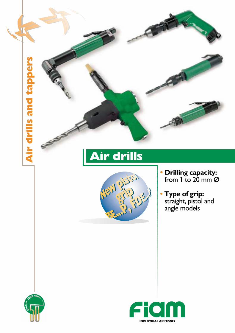
•• Drilling capacity:from 1 to 20 mm Ø
• Type of grip:straight, pistol andangle models
Air drillsAir
dri
lls
and
tap
pers
INDUSTRIAL AIR TOOLSJuly
200
0 -
34
Pri
nted
on
recy
cled
pap
er fo
r th
e sa
fegu
ard
of t
he e
nvir
onm
ent
INDUSTRIAL AIR TOOLS Quality CertificationUNI EN ISO 9001 / ICIM 0250
Environmental Management System CertificateUNI EN ISO 14001 / ICIM 0002A/0
Fiam Utensili Pneumatici spaViale Crispi, 123 - 36100 Vicenza / ItalyTel. +39.0444.562611 - Fax +39.0444.562325customerservice@fiamairtools.comwww.fiamairtools.com
Choosing the right air drills
The main technological parameters in drilling operations are the cuttingspeed and the force with which the drill is moved forwards, both of whichare in their turn connected with the type of material being drilled, thediameter of the hole and the idle speed of the drill.Fiam air drills offer considerable advantages, combining high performancewith an excellent power to weight ratio and design features that makethem particularly easy-to-handle.The range includes various models with straight and pistol grip, or angledrills suitable to drill from 1 to 20 mm diameter; equipped with differentkinds of chucks to fix the bits (self-locking chucks and keyed chucks), andmodels with collet chucks.
The FSE, FDE and FY series are the most used for their practicality,handiness and lightness in relation to their performances. The capacities ofthe chucks supplied with the tool vary from 0 to 16 mm and the speedsfrom 450 to 20.000 r.p.m.
There are available the FZ series, extremely compact, the FS and FYseries. The capacities of the chucks supplied with the tool vary from 0 to 10 mm and the speeds from 500 to 20.000 r.p.m.An important benefit is that they can be started at low speed, using alever, to facilitate initial insertion of the bit.
Suitable for holes with a diameter of over 10-13 mm. FO air drills can alsobe used for boring and tightening.
Drills with angle heads of 30° and 90° are suitable for drilling in tight spaceswhere access is difficult. Speeds vary from 500 to 4.500 r.p.m.
All Fiam air drills ccan be used as screwdrivers; it is sufficient to changethe chuck to obtain a screwdriver (without clutch) practical, light and easyto handle.
Fiam designs and manufactures special drills to meet the specific needs ofindividual clients.Fiam Technical Assistance Service is at your disposal for further details.
Special and multi spindle drills
Drills-Screwdrivers
Angle drills
Twin grip drills
Straight grip drills
Pistol grip drills
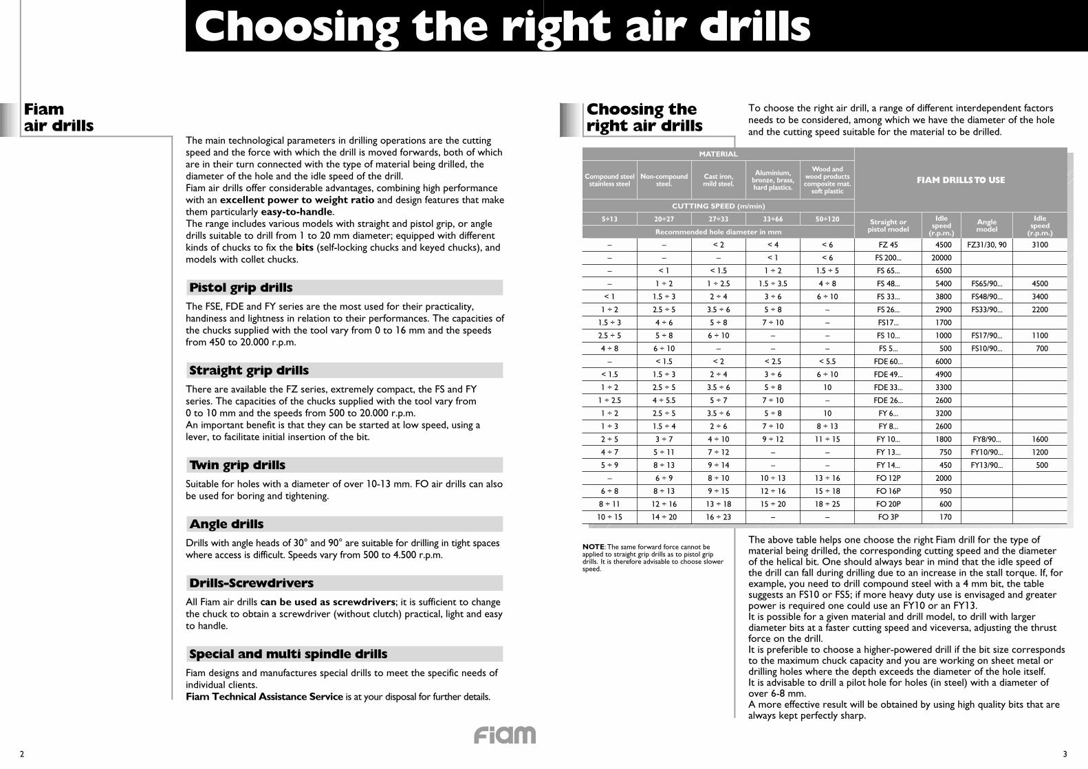
To choose the right air drill, a range of different interdependent factorsneeds to be considered, among which we have the diameter of the holeand the cutting speed suitable for the material to be drilled.
The above table helps one choose the right Fiam drill for the type ofmaterial being drilled, the corresponding cutting speed and the diameterof the helical bit. One should always bear in mind that the idle speed ofthe drill can fall during drilling due to an increase in the stall torque. If, forexample, you need to drill compound steel with a 4 mm bit, the tablesuggests an FS10 or FS5; if more heavy duty use is envisaged and greaterpower is required one could use an FY10 or an FY13.It is possible for a given material and drill model, to drill with largerdiameter bits at a faster cutting speed and viceversa, adjusting the thrustforce on the drill.It is preferible to choose a higher-powered drill if the bit size correspondsto the maximum chuck capacity and you are working on sheet metal ordrilling holes where the depth exceeds the diameter of the hole itself.It is advisable to drill a pilot hole for holes (in steel) with a diameter ofover 6-8 mm.A more effective result will be obtained by using high quality bits that arealways kept perfectly sharp.
Fiamair drills
Choosing theright air drills
2 3
MATERIAL
CUTTING SPEED (m/min)
Recommended hole diameter in mm
Compound steelstainless steel
5÷13 20÷27 27÷33 33÷66 50÷120 Straight orpistol model
Idlespeed
(r.p.m.)
Anglemodel
Idlespeed
(r.p.m.)
Non-compoundsteel.
Cast iron,mild steel.
Aluminium,bronze, brass,hard plastics.
Wood andwood productscomposite mat.
soft plasticFIAM DRILLS TO USE
– – < 2 < 4 < 6 FZ 45 4500 FZ31/30, 90 3100
– – – < 1 < 6 FS 200... 20000
– < 1 < 1.5 1 ÷ 2 1.5 ÷ 5 FS 65... 6500
– 1 ÷ 2 1 ÷ 2.5 1.5 ÷ 3.5 4 ÷ 8 FS 48... 5400 FS65/90... 4500
< 1 1.5 ÷ 3 2 ÷ 4 3 ÷ 6 6 ÷ 10 FS 33... 3800 FS48/90... 3400
1 ÷ 2 2.5 ÷ 5 3.5 ÷ 6 5 ÷ 8 – FS 26... 2900 FS33/90... 2200
1.5 ÷ 3 4 ÷ 6 5 ÷ 8 7 ÷ 10 – FS17... 1700
2.5 ÷ 5 5 ÷ 8 6 ÷ 10 – – FS 10... 1000 FS17/90... 1100
4 ÷ 8 6 ÷ 10 – – – FS 5... 500 FS10/90... 700
– < 1.5 < 2 < 2.5 < 5.5 FDE 60... 6000
< 1.5 1.5 ÷ 3 2 ÷ 4 3 ÷ 6 6 ÷ 10 FDE 49... 4900
1 ÷ 2 2.5 ÷ 5 3.5 ÷ 6 5 ÷ 8 10 FDE 33... 3300
1 ÷ 2.5 4 ÷ 5.5 5 ÷ 7 7 ÷ 10 – FDE 26... 2600
1 ÷ 2 2.5 ÷ 5 3.5 ÷ 6 5 ÷ 8 10 FY 6... 3200
1 ÷ 3 1.5 ÷ 4 2 ÷ 6 7 ÷ 10 8 ÷ 13 FY 8... 2600
2 ÷ 5 3 ÷ 7 4 ÷ 10 9 ÷ 12 11 ÷ 15 FY 10... 1800 FY8/90... 1600
4 ÷ 7 5 ÷ 11 7 ÷ 12 – – FY 13... 750 FY10/90... 1200
5 ÷ 9 8 ÷ 13 9 ÷ 14 – – FY 14... 450 FY13/90... 500
– 6 ÷ 9 8 ÷ 10 10 ÷ 13 13 ÷ 16 FO 12P 2000
6 ÷ 8 8 ÷ 13 9 ÷ 15 12 ÷ 16 15 ÷ 18 FO 16P 950
8 ÷ 11 12 ÷ 16 13 ÷ 18 15 ÷ 20 18 ÷ 25 FO 20P 600
10 ÷ 15 14 ÷ 20 16 ÷ 23 – – FO 3P 170
NOTE: The same forward force cannot beapplied to straight grip drills as to pistol gripdrills. It is therefore advisable to choose slowerspeed.
Choosing the right air drills
Type of grip It is generally best to use straight grip drills for vertical drillingoperations and pistol grip for horizontal work.The pistol grip is better for holes larger than 6-8 mm because it permitsthe best advancing force.In order to contrast any possible torque reaction on wrist, Fiam equipsall the straight and pistol drills (except for the FZ series) withthe auxiliary grip (in accordance with prEN792 1-12 standard).FO air drills are provided with double grip, because they are used inheavy duty operations.As regards the type of grip, Fiam air drills are characterized by advancedergonomic solutions that allow different grip position, thanks to roundedshapes, without sharp edges. They can also be used by ambidexter andfor small hands.Different types of grips, to suit every possible work situation,are available for FSE and FDE pistol model, to guide the bit withprecision and safety and to avoid harmful strain of the wrist.The grip of Fiam straight drills presents an optimized diameter andgeometry combined with a special non-slip grip, enabling the operator toovercome the torque reaction and axial force exerted by drill in themost effective way.The special plastic material, in the straight versions, guarantees the rightdegree of softness to the grip and provides an effective handinsulation.
Idle speed From 170 to 20.000 r.p.m.
Startingsystem
Straight and angle air drills are started using the lever, while the pistolmodels by pushbutton.Some models are provided with low pressure push button, tofacilitate the operation when starting and during the drilling operation.Fiam air drills can be started at low speed and therefore facilitateinitial insertion of the bit.
4 5
Ergonomicfactors
In special manual drilling situations and drilling-equipment mountedapplications, Fiam manufactures special drills, in a very widerange of speeds, with direct air inlet for remote control use, and withsmooth or flanged housings.Given the wide variety of solutions possible, Fiam’s qualified TechnicalAssistance Service is at your disposal for any further information.
Special drills
Ergonomic factors play an important role in operator comfort and safetyas well as improving the working environment: essential factors inreducing production stops and the number of rejects, in addition toimproving finished product quality.Fiam has developed, starting from the design, air drills with vibrationslevel below 2,5 m/sec2, with low noise level, safeguarding theenvironment, light and easy to handle.As regards the reduction of the vibrations level, it is advisable to choose,where it is possible, pistol air drills, that transmit less vibrations thanstraight model and to use shorter helical drill bits.Another important parameter to consider in a drill is a low noise level.Fiam air drills are endowed with an effective exhaust silencing system;moreover all comply with the international standards in force.The careful design of the internal gears has also made it possible to get asignificant reduction in mechanical noise.Technological developments have made it possible to develop drills(except FO models) which use unlubricated compressed air. Themost important advantage offered by this system is that it eliminates allfog oil emission in the exhaust air.This benefits both the operator and delicate workpieces (electronics,precision mechanics), while also eliminating lubrication plant costs.Drill weight is an important factor contributing to operator fatigue; thegrip design and lightweight alloy parts used in Fiam drills enable theentire range to offer lower weight and greater handiness compared toequal performances.
Straight air drills FZ, FS, FY
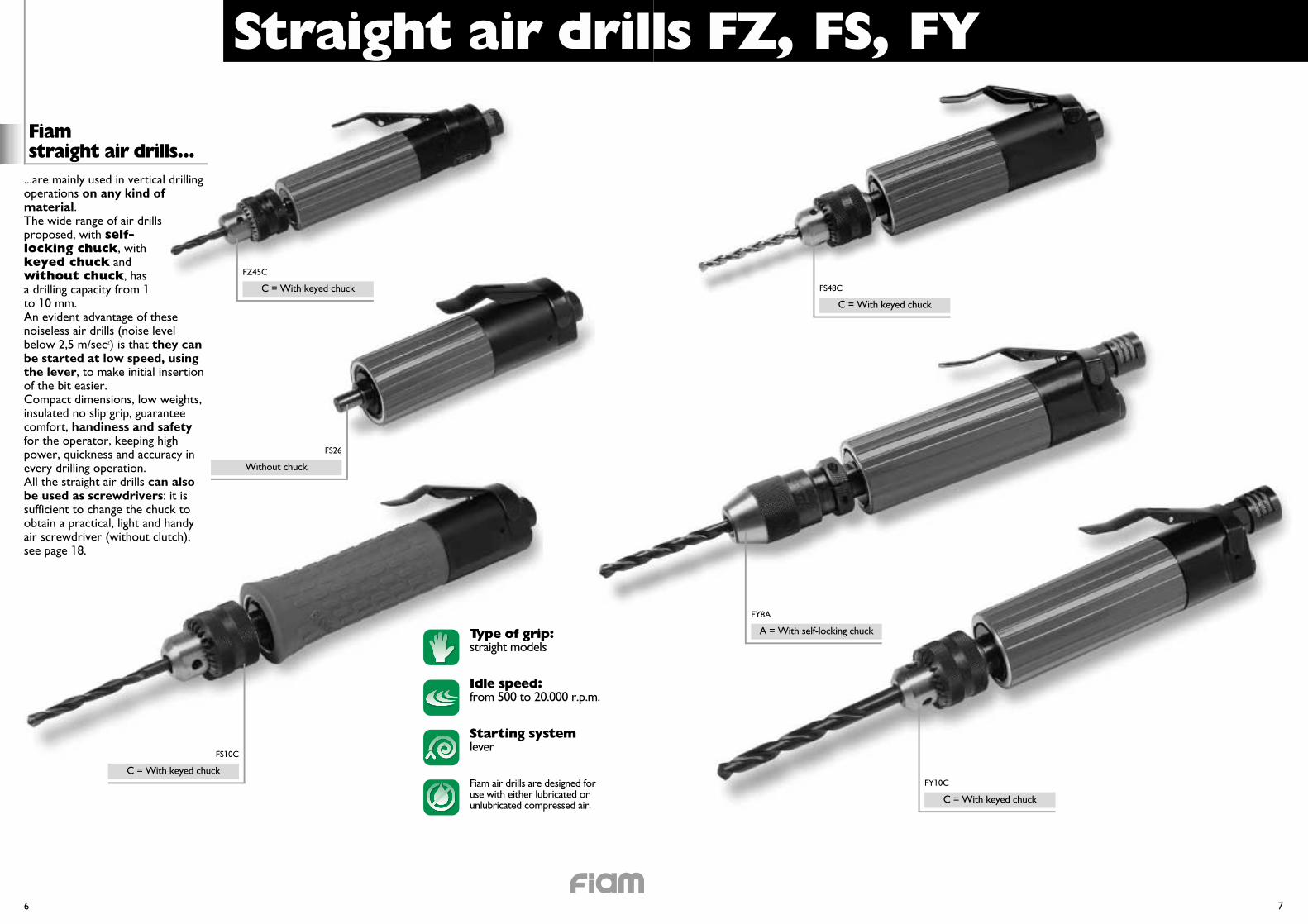
...are mainly used in vertical drillingoperations on any kind ofmaterial.The wide range of air drillsproposed, with self-locking chuck, withkeyed chuck andwithout chuck, hasa drilling capacity from 1to 10 mm.An evident advantage of thesenoiseless air drills (noise levelbelow 2,5 m/sec2) is that they canbe started at low speed, usingthe lever, to make initial insertionof the bit easier.Compact dimensions, low weights,insulated no slip grip, guaranteecomfort, handiness and safetyfor the operator, keeping highpower, quickness and accuracy inevery drilling operation.All the straight air drills can alsobe used as screwdrivers: it issufficient to change the chuck toobtain a practical, light and handyair screwdriver (without clutch),see page 18.
Fiamstraight air drills...
Starting systemlever
Idle speed:from 500 to 20.000 r.p.m.
Type of grip:straight models
Fiam air drills are designed foruse with either lubricated orunlubricated compressed air.
FS10C
6 7
C = With keyed chuck
FS26
Without chuck
FZ45C
C = With keyed chuck FS48C
C = With keyed chuck
FY8A
A = With self-locking chuck
FY10C
C = With keyed chuck
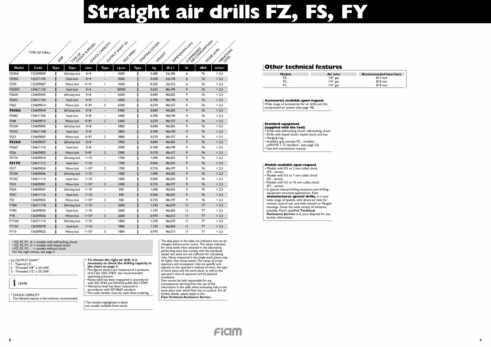
Straight air drills FZ, FS, FY
8 9
TYPE OF DRILL
Model Code Type Type mm Type r.p.m. Type kg Ø x l l/s dBA m/sec2
FZ45A
FZ45C
FZ45
FS200C
FS65A
FS65C
FS65
FS48A
FS48C
FS48
FS33A
FS33C
FS33
FS26A
FS26C
FS26
FS17A
FS17C
FS17
FS10A
FS10C
FS10
FS5A
FS5C
FS5
FY8A
FY8C
FY8
FY10A
FY10C
FY10
122309009
122311145
122309007
124611120
124609043
124611104
124609014
124609044
124611106
124609015
124609045
124611108
124609003
124609037
124611110
124609002
124609010
124611112
124609054
124609046
124611114
124609001
124609047
124611116
124609055
126311118
126309024
126309026
126311110
126309078
126309023
Self-locking chuck
Keyed chuck
Without chuck
Keyed chuck
Self-locking chuck
Keyed chuck
Without chuck
Self-locking chuck
Keyed chuck
Without chuck
Self-locking chuck
Keyed chuck
Without chuck
Self-locking chuck
Keyed chuck
Without chuck
Self-locking chuck
Keyed chuck
Without chuck
Self-locking chuck
Keyed chuck
Without chuck
Self-locking chuck
Keyed chuck
Without chuck
Self-locking chuck
Keyed chuck
Without chuck
Self-locking chuck
Keyed chuck
Without chuck
0÷4
0÷4
0÷4*
0÷6
0÷8
0÷8
0÷8*
0÷8
0÷8
0÷8*
0÷8
0÷8
0÷8*
0÷8
0÷8
0÷8*
1÷10
1÷10
1÷10*
1÷10
1÷10
1÷10*
1÷10
1÷10
1÷10*
1÷10
1÷10
1÷10*
1÷10
1÷10
1÷10*
4500
4500
4500
20000
6500
6500
6500
5400
5400
5400
3800
3800
3800
2900
2900
2900
1700
1700
1700
1000
1000
1000
500
500
500
2600
2600
2600
1800
1800
1800
6
6
6
9
9
9
9
9
9
9
9
9
9
9
9
9
9
9
9
9
9
9
9
9
9
11
11
11
11
11
11
–
–
1
–
–
–
2
–
–
2
–
–
2
–
–
2
–
–
2
–
–
2
–
–
2
–
–
3
–
–
3
76
76
76
76
76
76
76
76
76
76
76
76
76
76
76
76
76
76
76
76
76
76
76
76
76
77
77
77
77
77
77
< 2,5
< 2,5
< 2,5
< 2,5
< 2,5
< 2,5
< 2,5
< 2,5
< 2,5
< 2,5
< 2,5
< 2,5
< 2,5
< 2,5
< 2,5
< 2,5
< 2,5
< 2,5
< 2,5
< 2,5
< 2,5
< 2,5
< 2,5
< 2,5
< 2,5
< 2,5
< 2,5
< 2,5
< 2,5
< 2,5
< 2,5
GRIPTYPE
OF
CHUCK SUPP
LIED
CHUCK CAPA
CITY
START
ING SY
STEM
IDLE
SPEE
D
WEIG
HT
DIMEN
SIONS (
mm)
COMPR
ESSE
D
AIR C
ONSU
MPTIO
N
OUTPU
T SHAFT
(a)
NOISE
LEVEL
VIBRAT
IONS
LEVEL
The data given in the table are indicative and can bechanged without prior notice. The values indicatedfor noise levels were obtained in the laboratory,performing tests that comply with the standardsstated, but alone are not sufficient for calculatingrisks. Values measured in the single work places maybe higher than those stated. The values of actualexposure and consequent risks are specific anddepend on the operator’s method of work, the typeof work piece and the work place, as well as theoperator’s time of exposure and his physicalconditions.Fiam cannot be held responsible for anyconsequences deriving from the use of theinformation in the table when evaluating risks in thework place over which Fiam has no control. For allfurther details, please apply to the Fiam Technical Assistance Service.
(a) OUTPUT SHAFT1 - Tapered J 0.2 - Threaded 3/8” x 24 UNF.3 - Threaded 1/2” x 20 UNF.
The models highlighted in blackare usually available from stock.
* CHUCK CAPACITYThe indicated capacity is the maximum recommended.
LEVER
• To choose the right air drill, it isnecessary to check the drilling capacity inthe chart on page 3.
• The figures shown are measured at a pressureof 6,3 bar (ISO 2787), the recommendedoperating pressure.
• Noise level has been measured in accordancewith ISO 3744 and ISO/DIS-prEN ISO 15744.
• Vibrations level has been measured inaccordance with ISO 8662 standard.
• The code number must be used when ordering.
• FZ, FS, FY...A = models with self-locking chuck.• FZ, FS, FY...C = models with keyed chuck.• FZ, FS, FY...A = models without chuck.For the right choice, see page 3.
Other technical featuresModels
FZ...FS...FY...
1/8” gas1/4” gas1/4” gas
Ø 5 mmØ 8 mmØ 8 mm
Air inlet Recommended hose bore
Standard equipment(supplied with the tool)• Drills with self-locking chuck: self-locking chuck.• Drills with keyed chuck: keyed chuck and key.• Hanging ring.• Auxiliary grip (except FZ... models) -
prEN792 1-12 standard - (see page 23).• Use and maintenance manual.
Models available upon request• Models with 0.5 to 5 mm collet chuck
(FZ... series).• Models with 0.5 to 7 mm collet chuck
(FS... series).• Models with 0.5 to 10 mm collet chuck
(FY... series).• In special manual drilling situations and drilling-
equipment mounted applications, Fiammanufactures special drills, in a verywide range of speeds, with direct air inlet forremote control use, and with smooth or flangedhousings. Given the wide variety of solutionspossible, Fiam’s qualified TechnicalAssistance Service is at your disposal for anyfurther information.
Accessories available upon requestWide range of accessories for air drills and thecompressed air system (see page 18).
0,480
0,430
0,350
0,625
0,840
0,700
0,570
0,840
0,700
0,570
0,840
0,700
0,570
0,840
0,700
0,570
1,090
0,960
0,735
1,090
0,960
0,735
1,090
0,960
0,735
1,330
1,195
0,970
1,330
1,195
0,970
32x185
32x178
32x153
40x190
40x205
40x190
40x157
40x205
40x190
40x157
40x205
40x190
40x157
40x205
40x190
40x157
40x255
40x235
40x197
40x255
40x235
40x197
40x255
40x235
40x197
46x270
46x250
46x213
46x270
46x250
46x213
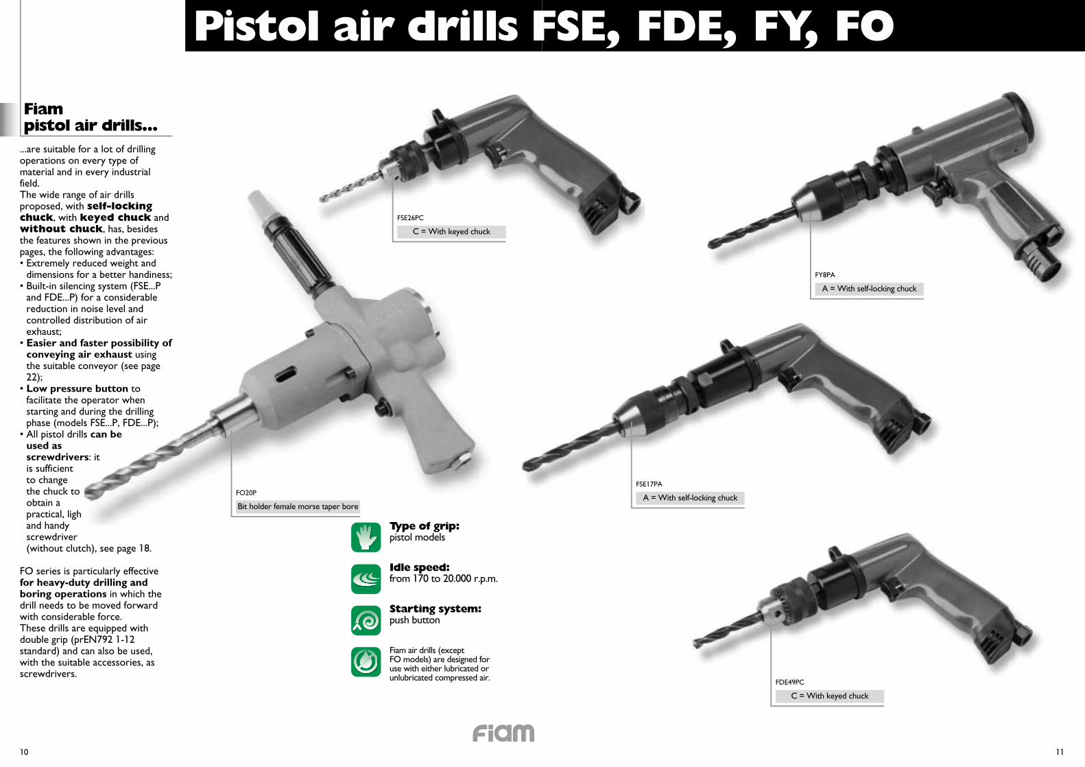
Pistol air drills FSE, FDE, FY, FO
Fiam pistol air drills...
Starting system:push button
Idle speed:from 170 to 20.000 r.p.m.
Type of grip:pistol models
Fiam air drills (except FO models) are designed foruse with either lubricated orunlubricated compressed air.
10 11
...are suitable for a lot of drillingoperations on every type ofmaterial and in every industrialfield.The wide range of air drillsproposed, with self-lockingchuck, with keyed chuck andwithout chuck, has, besidesthe features shown in the previouspages, the following advantages:• Extremely reduced weight and
dimensions for a better handiness;• Built-in silencing system (FSE...P
and FDE...P) for a considerablereduction in noise level andcontrolled distribution of airexhaust;
• Easier and faster possibility ofconveying air exhaust usingthe suitable conveyor (see page22);
• Low pressure button tofacilitate the operator whenstarting and during the drillingphase (models FSE...P, FDE...P);
• All pistol drills can beused asscrewdrivers: itis sufficientto changethe chuck toobtain apractical, lightand handyscrewdriver(without clutch), see page 18.
FO series is particularly effectivefor heavy-duty drilling andboring operations in which thedrill needs to be moved forwardwith considerable force.These drills are equipped withdouble grip (prEN792 1-12standard) and can also be used,with the suitable accessories, asscrewdrivers.
FO20P
Bit holder female morse taper bore
FSE26PC
C = With keyed chuck
FDE49PC
C = With keyed chuck
FSE17PA
A = With self-locking chuck
FY8PA
A = With self-locking chuck
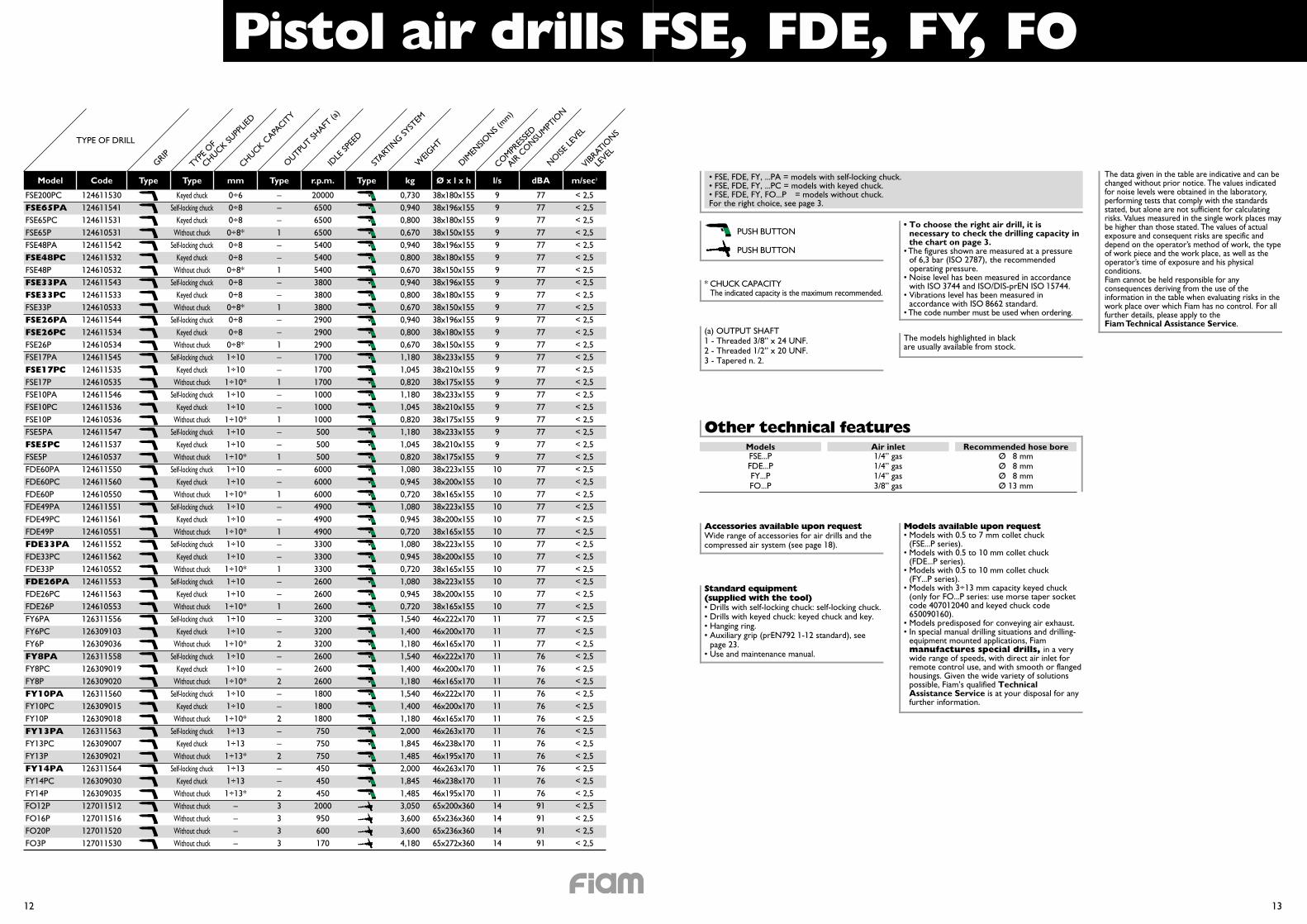
Pistol air drills FSE, FDE, FY, FO
12 13
Model Code Type Type mm Type r.p.m. Type kg Ø x l x h l/s dBA m/sec2
FSE200PCFSE65PAFSE65PCFSE65PFSE48PAFSE48PCFSE48PFSE33PAFSE33PCFSE33PFSE26PAFSE26PCFSE26PFSE17PAFSE17PCFSE17PFSE10PAFSE10PCFSE10PFSE5PAFSE5PCFSE5PFDE60PAFDE60PCFDE60PFDE49PAFDE49PCFDE49PFDE33PAFDE33PCFDE33PFDE26PAFDE26PCFDE26PFY6PAFY6PCFY6PFY8PAFY8PCFY8PFY10PAFY10PCFY10PFY13PAFY13PCFY13PFY14PAFY14PCFY14PFO12PFO16PFO20PFO3P
124611530124611541124611531124610531124611542124611532124610532124611543124611533124610533124611544124611534124610534124611545124611535124610535124611546124611536124610536124611547124611537124610537124611550124611560124610550124611551124611561124610551124611552124611562124610552124611553124611563124610553126311556126309103126309036126311558126309019126309020126311560126309015126309018126311563126309007126309021126311564126309030126309035127011512127011516127011520127011530
Keyed chuckSelf-locking chuck
Keyed chuckWithout chuck
Self-locking chuckKeyed chuck
Without chuckSelf-locking chuck
Keyed chuckWithout chuck
Self-locking chuckKeyed chuck
Without chuckSelf-locking chuck
Keyed chuckWithout chuck
Self-locking chuckKeyed chuck
Without chuckSelf-locking chuck
Keyed chuckWithout chuck
Self-locking chuckKeyed chuck
Without chuckSelf-locking chuck
Keyed chuckWithout chuck
Self-locking chuckKeyed chuck
Without chuckSelf-locking chuck
Keyed chuckWithout chuck
Self-locking chuckKeyed chuck
Without chuckSelf-locking chuck
Keyed chuckWithout chuck
Self-locking chuckKeyed chuck
Without chuckSelf-locking chuck
Keyed chuckWithout chuck
Self-locking chuckKeyed chuck
Without chuckWithout chuckWithout chuckWithout chuckWithout chuck
0÷60÷80÷80÷8*0÷80÷80÷8*0÷80÷80÷8*0÷80÷80÷8*1÷101÷101÷10*1÷101÷101÷10*1÷101÷101÷10*1÷101÷101÷10*1÷101÷101÷10*1÷101÷101÷10*1÷101÷101÷10*1÷101÷101÷10*1÷101÷101÷10*1÷101÷101÷10*1÷131÷131÷13*1÷131÷131÷13*
––––
200006500650065005400540054003800380038002900290029001700170017001000100010005005005006000600060004900490049003300330033002600260026003200320032002600260026001800180018007507507504504504502000950600170
999999999999999999999910101010101010101010101011111111111111111111111111111114141414
–––1––1––1––1––1––1––1––1––1––1––1––2––2––2––2––23333
7777777777777777777777777777777777777777777777777777777777777777777777777776767676767676767676767691919191
< 2,5< 2,5< 2,5< 2,5< 2,5< 2,5< 2,5< 2,5< 2,5< 2,5< 2,5< 2,5< 2,5< 2,5< 2,5< 2,5< 2,5< 2,5< 2,5< 2,5< 2,5< 2,5< 2,5< 2,5< 2,5< 2,5< 2,5< 2,5< 2,5< 2,5< 2,5< 2,5< 2,5< 2,5< 2,5< 2,5< 2,5< 2,5< 2,5< 2,5< 2,5< 2,5< 2,5< 2,5< 2,5< 2,5< 2,5< 2,5< 2,5< 2,5< 2,5< 2,5< 2,5
The data given in the table are indicative and can bechanged without prior notice. The values indicatedfor noise levels were obtained in the laboratory,performing tests that comply with the standardsstated, but alone are not sufficient for calculatingrisks. Values measured in the single work places maybe higher than those stated. The values of actualexposure and consequent risks are specific anddepend on the operator’s method of work, the typeof work piece and the work place, as well as theoperator’s time of exposure and his physicalconditions.Fiam cannot be held responsible for anyconsequences deriving from the use of theinformation in the table when evaluating risks in thework place over which Fiam has no control. For allfurther details, please apply to the Fiam Technical Assistance Service.
PUSH BUTTON
PUSH BUTTON
• FSE, FDE, FY, ...PA = models with self-locking chuck.• FSE, FDE, FY, ...PC = models with keyed chuck.• FSE, FDE, FY, FO...PC = models without chuck.For the right choice, see page 3.
Other technical featuresModelsFSE...PFDE...PFY...PFO...P
1/4” gas1/4” gas1/4” gas3/8” gas
Ø 8 mmØ 8 mmØ 8 mmØ 13 mm
Air inlet Recommended hose bore
Models available upon request• Models with 0.5 to 7 mm collet chuck
(FSE...P series).• Models with 0.5 to 10 mm collet chuck
(FDE...P series).• Models with 0.5 to 10 mm collet chuck
(FY...P series).• Models with 3÷13 mm capacity keyed chuck
(only for FO...P series: use morse taper socketcode 407012040 and keyed chuck code650090160).
• Models predisposed for conveying air exhaust.• In special manual drilling situations and drilling-
equipment mounted applications, Fiammanufactures special drills, in a verywide range of speeds, with direct air inlet forremote control use, and with smooth or flangedhousings. Given the wide variety of solutionspossible, Fiam’s qualified TechnicalAssistance Service is at your disposal for anyfurther information.
(a) OUTPUT SHAFT1 - Threaded 3/8” x 24 UNF.2 - Threaded 1/2” x 20 UNF.3 - Tapered n. 2.
Accessories available upon requestWide range of accessories for air drills and thecompressed air system (see page 18).
TYPE OF DRILL
GRIPTYPE
OF
CHUCK SUPP
LIED
CHUCK CAPA
CITY
START
ING SY
STEM
IDLE
SPEE
D
WEIG
HT
DIMEN
SIONS (
mm)
COMPR
ESSE
D
AIR C
ONSU
MPTIO
N
OUTPU
T SHAFT
(a)
NOISE
LEVEL
VIBRAT
IONS
LEVEL
• To choose the right air drill, it isnecessary to check the drilling capacity inthe chart on page 3.
• The figures shown are measured at a pressureof 6,3 bar (ISO 2787), the recommendedoperating pressure.
• Noise level has been measured in accordancewith ISO 3744 and ISO/DIS-prEN ISO 15744.
• Vibrations level has been measured inaccordance with ISO 8662 standard.
• The code number must be used when ordering.
Standard equipment(supplied with the tool)• Drills with self-locking chuck: self-locking chuck.• Drills with keyed chuck: keyed chuck and key.• Hanging ring.• Auxiliary grip (prEN792 1-12 standard), see
page 23.• Use and maintenance manual.
The models highlighted in blackare usually available from stock.
* CHUCK CAPACITYThe indicated capacity is the maximum recommended.
0,7300,9400,8000,6700,9400,8000,6700,9400,8000,6700,9400,8000,6701,1801,0450,8201,1801,0450,8201,1801,0450,8201,0800,9450,7201,0800,9450,7201,0800,9450,7201,0800,9450,7201,5401,4001,1801,5401,4001,1801,5401,4001,1802,0001,8451,4852,0001,8451,4853,0503,6003,6004,180
38x180x15538x196x15538x180x15538x150x15538x196x15538x180x15538x150x15538x196x15538x180x15538x150x15538x196x15538x180x15538x150x15538x233x15538x210x15538x175x15538x233x15538x210x15538x175x15538x233x15538x210x15538x175x15538x223x15538x200x15538x165x15538x223x15538x200x15538x165x15538x223x15538x200x15538x165x15538x223x15538x200x15538x165x15546x222x17046x200x17046x165x17046x222x17046x200x17046x165x17046x222x17046x200x17046x165x17046x263x17046x238x17046x195x17046x263x17046x238x17046x195x17065x200x36065x236x36065x236x36065x272x360
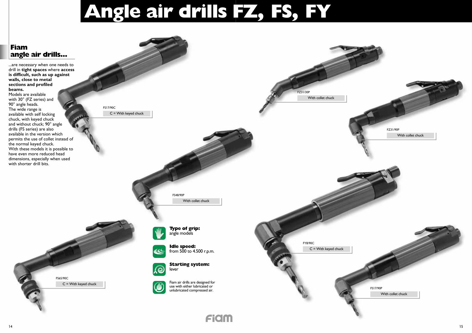
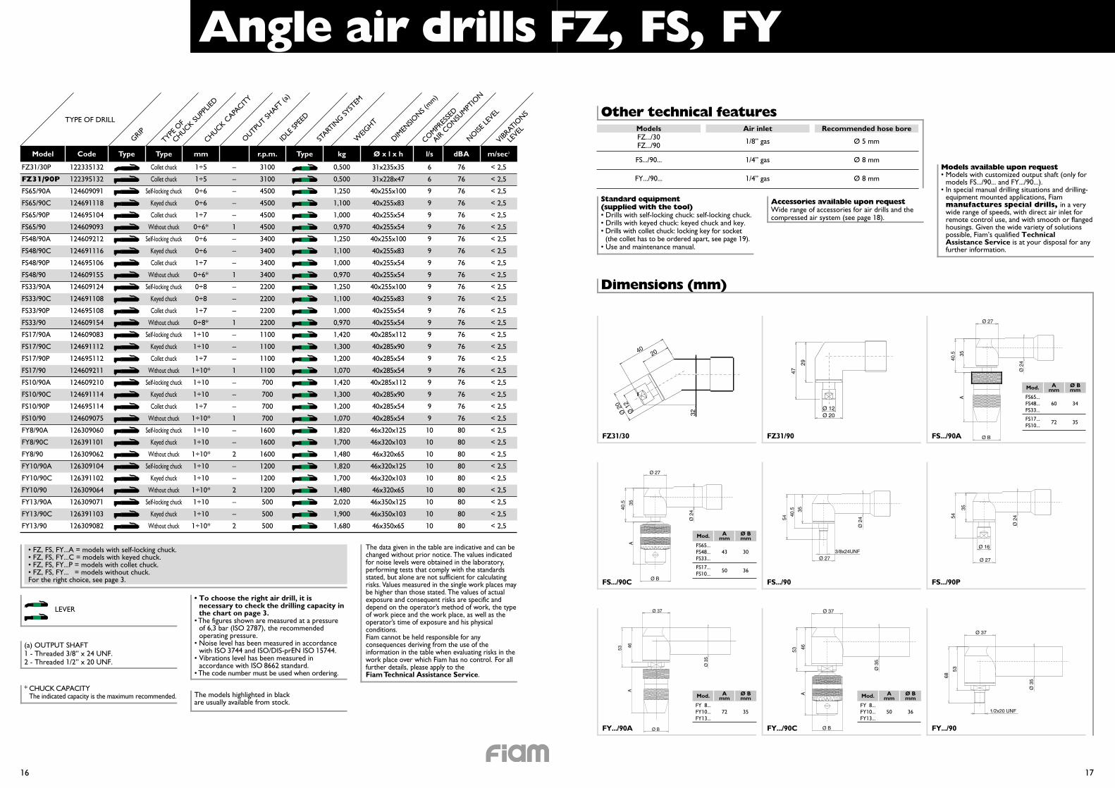
Angle air drills FZ, FS, FY
Fiamangle air drills...
Starting system:lever
Idle speed:from 500 to 4.500 r.p.m.
Type of grip:angle models
Fiam air drills are designed foruse with either lubricated orunlubricated compressed air.
14 15
...are necessary when one needs todrill in tight spaces where accessis difficult, such as up againstwalls, close to metalsections and profiledbeams.Models are availablewith 30° (FZ series) and90° angle heads.The wide range isavailable with self lockingchuck, with keyed chuckand without chuck; 90° angledrills (FS series) are alsoavailable in the version whichpermits the use of collet instead ofthe normal keyed chuck.With these models it is possible tohave even more reduced headdimensions, especially when usedwith shorter drill bits.
FS17/90C
C = With keyed chuck
FS48/90P
With collet chuck
FS65/90C
C = With keyed chuck
FZ31/30P
With collet chuck
FZ31/90P
With collet chuck
FY8/90C
C = With keyed chuck
FS17/90P
With collet chuck
Angle air drills FZ, FS, FY
16 17
Model Code Type Type mm r.p.m. Type kg Ø x l x h l/s dBA m/sec2
FZ31/30P
FZ31/90P
FS65/90A
FS65/90C
FS65/90P
FS65/90
FS48/90A
FS48/90C
FS48/90P
FS48/90
FS33/90A
FS33/90C
FS33/90P
FS33/90
FS17/90A
FS17/90C
FS17/90P
FS17/90
FS10/90A
FS10/90C
FS10/90P
FS10/90
FY8/90A
FY8/90C
FY8/90
FY10/90A
FY10/90C
FY10/90
FY13/90A
FY13/90C
FY13/90
122335132
122395132
124609091
124691118
124695104
124609093
124609212
124691116
124695106
124609155
124609124
124691108
124695108
124609154
124609083
124691112
124695112
124609211
124609210
124691114
124695114
124609075
126309060
126391101
126309062
126309104
126391102
126309064
126309071
126391103
126309082
Collet chuck
Collet chuck
Self-locking chuck
Keyed chuck
Collet chuck
Without chuck
Self-locking chuck
Keyed chuck
Collet chuck
Without chuck
Self-locking chuck
Keyed chuck
Collet chuck
Without chuck
Self-locking chuck
Keyed chuck
Collet chuck
Without chuck
Self-locking chuck
Keyed chuck
Collet chuck
Without chuck
Self-locking chuck
Keyed chuck
Without chuck
Self-locking chuck
Keyed chuck
Without chuck
Self-locking chuck
Keyed chuck
Without chuck
1÷5
1÷5
0÷6
0÷6
1÷7
0÷6*
0÷6
0÷6
1÷7
0÷6*
0÷8
0÷8
1÷7
0÷8*
1÷10
1÷10
1÷7
1÷10*
1÷10
1÷10
1÷7
1÷10*
1÷10
1÷10
1÷10*
1÷10
1÷10
1÷10*
1÷10
1÷10
1÷10*
–
–
–
–
–
1
–
–
–
1
–
–
–
1
–
–
–
1
–
–
–
1
–
–
2
–
–
2
–
–
2
3100
3100
4500
4500
4500
4500
3400
3400
3400
3400
2200
2200
2200
2200
1100
1100
1100
1100
700
700
700
700
1600
1600
1600
1200
1200
1200
500
500
500
6
6
9
9
9
9
9
9
9
9
9
9
9
9
9
9
9
9
9
9
9
9
10
10
10
10
10
10
10
10
10
76
76
76
76
76
76
76
76
76
76
76
76
76
76
76
76
76
76
76
76
76
76
80
80
80
80
80
80
80
80
80
< 2,5
< 2,5
< 2,5
< 2,5
< 2,5
< 2,5
< 2,5
< 2,5
< 2,5
< 2,5
< 2,5
< 2,5
< 2,5
< 2,5
< 2,5
< 2,5
< 2,5
< 2,5
< 2,5
< 2,5
< 2,5
< 2,5
< 2,5
< 2,5
< 2,5
< 2,5
< 2,5
< 2,5
< 2,5
< 2,5
< 2,5
The data given in the table are indicative and can bechanged without prior notice. The values indicatedfor noise levels were obtained in the laboratory,performing tests that comply with the standardsstated, but alone are not sufficient for calculatingrisks. Values measured in the single work places maybe higher than those stated. The values of actualexposure and consequent risks are specific anddepend on the operator’s method of work, the typeof work piece and the work place, as well as theoperator’s time of exposure and his physicalconditions.Fiam cannot be held responsible for anyconsequences deriving from the use of theinformation in the table when evaluating risks in thework place over which Fiam has no control. For allfurther details, please apply to the Fiam Technical Assistance Service.
LEVER
• FZ, FS, FY...A = models with self-locking chuck.• FZ, FS, FY...C = models with keyed chuck.• FZ, FS, FY...P = models with collet chuck.• FZ, FS, FY...P = models without chuck.For the right choice, see page 3.
Other technical featuresModelsFZ.../30FZ.../90
FS.../90...
FY.../90...
1/8” gas
1/4” gas
1/4” gas
Ø 5 mm
Ø 8 mm
Ø 8 mm
Air inlet Recommended hose bore
Dimensions (mm)
Standard equipment(supplied with the tool)• Drills with self-locking chuck: self-locking chuck.• Drills with keyed chuck: keyed chuck and key.• Drills with collet chuck: locking key for socket
(the collet has to be ordered apart, see page 19).• Use and maintenance manual.
Ø B
A
40.5 35
Ø 27
Ø 2
4
35
54
Ø 2
4
Ø 16
Ø 27
53
1/2x20 UNF
68
Ø 37
Ø 3
5
(a) OUTPUT SHAFT1 - Threaded 3/8” x 24 UNF.2 - Threaded 1/2” x 20 UNF.
FZ31/30 FZ31/90 FS.../90A
FS.../90C FS.../90 FS.../90P
40
.
20
32Ø 2
0
Ø 1
2
Ø B
A
40.5 35
Ø 27
Ø 2
4
A
Ø B
53 46
Ø 37
Ø 3
5
29
47
Ø 12Ø 20
40.5
3/8x24UNF
54
35
Ø 2
4
Ø 27
Ø B
A
53 46
Ø 37
Ø 3
5
FY.../90A FY.../90C FY.../90
Models available upon request• Models with customized output shaft (only for
models FS.../90... and FY.../90...).• In special manual drilling situations and drilling-
equipment mounted applications, Fiammanufactures special drills, in a verywide range of speeds, with direct air inlet forremote control use, and with smooth or flangedhousings. Given the wide variety of solutionspossible, Fiam’s qualified TechnicalAssistance Service is at your disposal for anyfurther information.
Accessories available upon requestWide range of accessories for air drills and thecompressed air system (see page 18).
AmmMod.
FS65...FS48...FS33...
FS17...FS10...
72 35
60 34
Ø Bmm
AmmMod.
FS65...FS48...FS33...
FS17...FS10...
50 36
43 30
Ø Bmm
AmmMod.
FY 8...FY10...FY13...
72 35
Ø Bmm
AmmMod.
FY 8...FY10...FY13...
50 36
Ø Bmm
TYPE OF DRILL
GRIPTYPE
OF
CHUCK SUPP
LIED
CHUCK CAPA
CITY
START
ING SY
STEM
IDLE
SPEE
D
WEIG
HT
DIMEN
SIONS (
mm)
COMPR
ESSE
D
AIR C
ONSU
MPTIO
N
OUTPU
T SHAFT
(a)
NOISE
LEVEL
VIBRAT
IONS
LEVEL
• To choose the right air drill, it isnecessary to check the drilling capacity inthe chart on page 3.
• The figures shown are measured at a pressureof 6,3 bar (ISO 2787), the recommendedoperating pressure.
• Noise level has been measured in accordancewith ISO 3744 and ISO/DIS-prEN ISO 15744.
• Vibrations level has been measured inaccordance with ISO 8662 standard.
• The code number must be used when ordering.
The models highlighted in blackare usually available from stock.
* CHUCK CAPACITYThe indicated capacity is the maximum recommended.
0,500
0,500
1,250
1,100
1,000
0,970
1,250
1,100
1,000
0,970
1,250
1,100
1,000
0,970
1,420
1,300
1,200
1,070
1,420
1,300
1,200
1,070
1,820
1,700
1,480
1,820
1,700
1,480
2,020
1,900
1,680
31x235x35
31x228x47
40x255x100
40x255x83
40x255x54
40x255x54
40x255x100
40x255x83
40x255x54
40x255x54
40x255x100
40x255x83
40x255x54
40x255x54
40x285x112
40x285x90
40x285x54
40x285x54
40x285x112
40x285x90
40x285x54
40x285x54
46x320x125
46x320x103
46x320x65
46x320x125
46x320x103
46x320x65
46x350x125
46x350x103
46x350x65
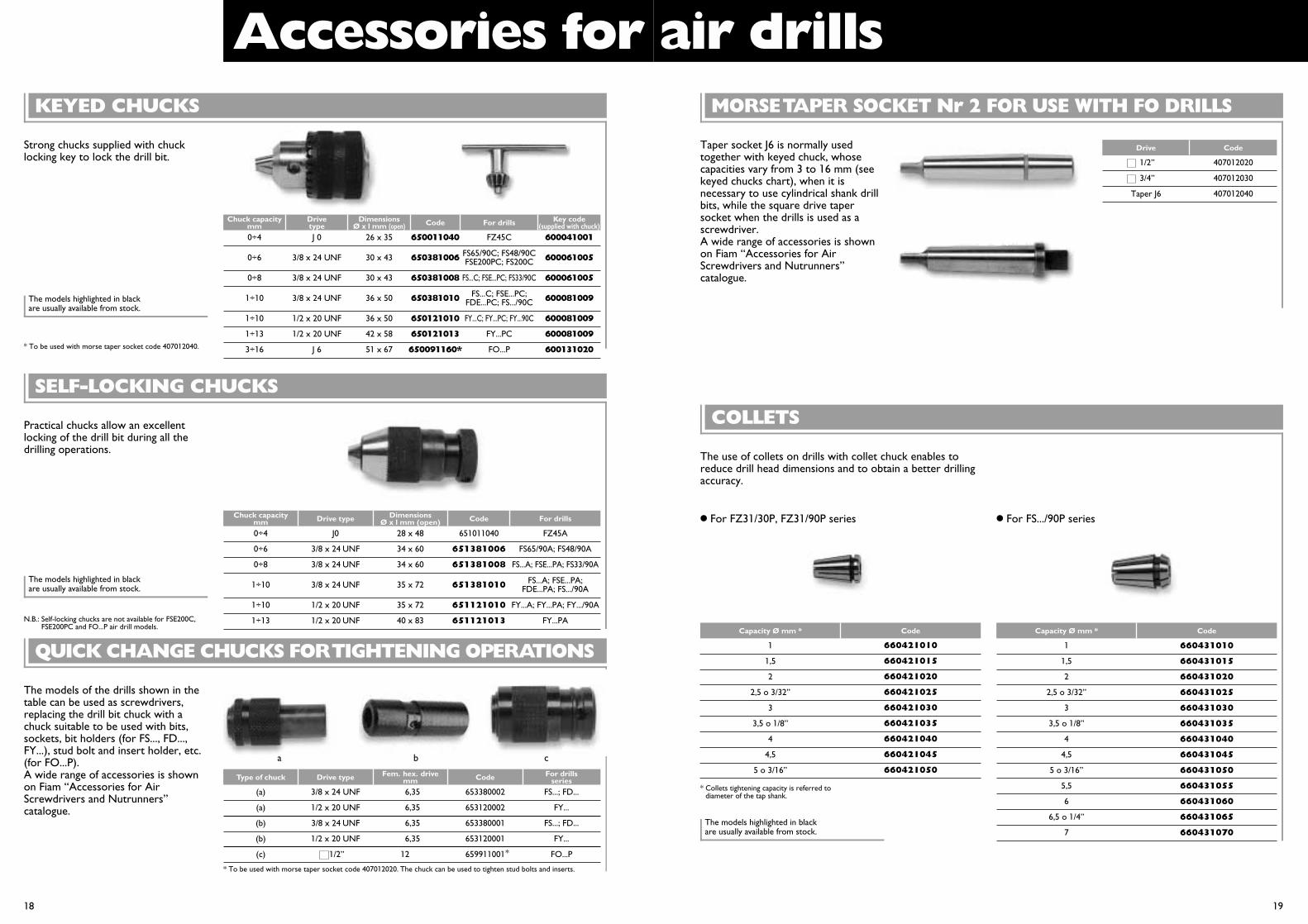
Strong chucks supplied with chucklocking key to lock the drill bit.
KEYED CHUCKS
Accessories for air drills
Chuck capacitymm
Drivetype
DimensionsØ x l mm (open) Code For drills Key code
(supplied with chuck)
SELF-LOCKING CHUCKS
18 19
Taper socket J6 is normally usedtogether with keyed chuck, whosecapacities vary from 3 to 16 mm (seekeyed chucks chart), when it isnecessary to use cylindrical shank drillbits, while the square drive tapersocket when the drills is used as ascrewdriver.A wide range of accessories is shownon Fiam “Accessories for AirScrewdrivers and Nutrunners”catalogue.
MORSE TAPER SOCKET Nr 2 FOR USE WITH FO DRILLS
Chuck capacitymm Drive type Dimensions
Ø x l mm (open) Code For drills
0÷4 J0 28 x 48 651011040 FZ45A
0÷6 3/8 x 24 UNF 34 x 60 651381006 FS65/90A; FS48/90A
0÷8 3/8 x 24 UNF 34 x 60 651381008 FS...A; FSE...PA; FS33/90A
1÷10 1/2 x 20 UNF 35 x 72 651121010 FY...A; FY...PA; FY.../90A
1÷13 1/2 x 20 UNF 40 x 83 651121013 FY...PA
1÷10 3/8 x 24 UNF 35 x 72 651381010 FS...A; FSE...PA;FDE...PA; FS.../90A
The models of the drills shown in thetable can be used as screwdrivers,replacing the drill bit chuck with achuck suitable to be used with bits,sockets, bit holders (for FS..., FD...,FY...), stud bolt and insert holder, etc.(for FO...P).A wide range of accessories is shownon Fiam “Accessories for AirScrewdrivers and Nutrunners”catalogue.
QUICK CHANGE CHUCKS FOR TIGHTENING OPERATIONS
Type of chuck Drive type Fem. hex. drivemm Code For drills
series
(a) 3/8 x 24 UNF 6,35 653380002 FS...; FD...
(a) 1/2 x 20 UNF 6,35 653120002 FY...
(b) 3/8 x 24 UNF 6,35 653380001 FS...; FD...
(b) 1/2 x 20 UNF 6,35 653120001 FY...
(c) 1/2” 12,00 659911001 FO...P*
* To be used with morse taper socket code 407012020. The chuck can be used to tighten stud bolts and inserts.
Drive Code
1/2” 407012020
3/4” 407012030
Taper J6 407012040
� For FZ31/30P, FZ31/90P series
The use of collets on drills with collet chuck enables toreduce drill head dimensions and to obtain a better drillingaccuracy.
COLLETS
Capacity Ø mm * Code
1
1,5
2
2,5 o 3/32”
3
3,5 o 1/8”
4
4,5
5 o 3/16”
660421010
660421015
660421020
660421025
660421030
660421035
660421040
660421045
660421050
Capacity Ø mm * Code
1 660431010
1,5 660431015
2 660431020
2,5 o 3/32” 660431025
3 660431030
3,5 o 1/8” 660431035
4 660431040
4,5 660431045
5 o 3/16” 660431050
5,5 660431055
6 660431060
6,5 o 1/4” 660431065
7 660431070
� For FS.../90P series
* To be used with morse taper socket code 407012040.
N.B.: Self-locking chucks are not available for FSE200C,FSE200PC and FO...P air drill models.
The models highlighted in blackare usually available from stock.
The models highlighted in blackare usually available from stock.
The models highlighted in blackare usually available from stock.
* Collets tightening capacity is referred todiameter of the tap shank.
a b c
Practical chucks allow an excellentlocking of the drill bit during all thedrilling operations.
0÷8 3/8 x 24 UNF 30 x 43 650381008 FS...C; FSE...PC; FS33/90C 600061005
1÷10 3/8 x 24 UNF 36 x 50 650381010 600081009
1÷10 1/2 x 20 UNF 36 x 50 650121010 FY...C; FY...PC; FY...90C 600081009
1÷13 1/2 x 20 UNF 42 x 58 650121013 FY...PC 600081009
3÷16 J 6 51 x 67 650091160* FO...P 600131020
FS...C; FSE...PC;FDE...PC; FS.../90C
FS65/90C; FS48/90CFSE200PC; FS200C
0÷4 J 0 26 x 35 650011040 FZ45C 600041001
0÷6 3/8 x 24 UNF 30 x 43 650381006 600061005
Hose Flow Filter Lubricator Gauge
ø mm l/s code code code code code * code
1/4” gas 1,7÷8,4 697331015 697031015 697131015 697281015 697339015 697312060
3/8” gas 4,2÷15 697351015 697051015 697151015 697291015 697339015 697312060
1/2” gas 8,4÷25 697371015 697071015 697171015 697301015 697339015 697312060
* N.B.: 2 assembly kits are needed for each FRL assembly (see items outlined).
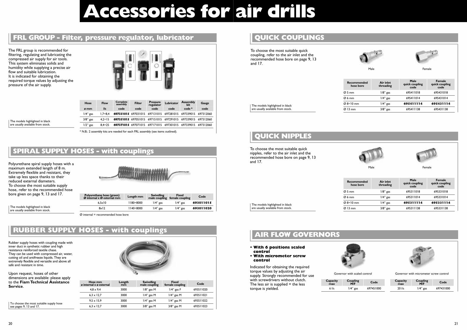
FRL GROUP - Filter, pressure regulator, lubricator
The FRL group is recommended forfiltering, regulating and lubricating thecompressed air supply for air tools.This system eliminates solids andhumidity while supplying a precise airflow and suitable lubrication.It is indicated for obtaining therequired torque values by adjusting thepressure of the air supply.
Completeassembly
Pressureregulator
Assemblykit
Polyurethane hose (green)Ø internal x Ø esternal mm Length mm Swivelling
male couplingFixed
female coupling Code
6,5x10 1180÷8000 1/4” gas 1/4” gas 693011015
8x12 1140÷8000 1/4” gas 1/4” gas 693011020
SPIRAL SUPPLY HOSES - with couplings
Polyurethane spiral supply hoses with amaximum extended length of 8 m.Extremely flexible and resistant, theytake up less space thanks to theirreduced external diameters.To choose the most suitable supplyhose, refer to the recommended hosebore given on page 9, 13 and 17.
Accessories for air drills
Ø 5 mm 1/8” gas 695411018 695431018
Ø 6 mm 1/4” gas 695411014 695431014
Ø 8÷10 mm 1/4” gas 695411114 695431114
Ø 13 mm 3/8” gas 695411138 695431138
QUICK COUPLINGS
To choose the most suitable quickcoupling, refer to the air inlet and therecommended hose bore on page 9, 13and 17.
Male Female
Recommendedhose bore
Air inletthreading
Malequick coupling
code
Femalequick coupling
code
QUICK NIPPLES
To choose the most suitable quicknipples, refer to the air inlet and therecommended hose bore on page 9, 13and 17.
Male Female
6 l/s 1/4” gas 697451000
AIR FLOW GOVERNORS
• With 6 positions scaledcontrol
• With micrometer screwcontrol
Indicated for obtaining the requiredtorque values by adjusting the airsupply. Strongly recommended for usewith screwdrivers without clutch.The less air is supplied = the lesstorque is yielded.
Governor with scaled control Governor with micrometer screw control
Capacitymax
CouplingM/F Code
20 l/s 1/4” gas 697431000
Capacitymax
CouplingM/F Code
Ø 5 mm 1/8” gas 695311018 695331018
Ø 6 mm 1/4” gas 695311014 695331014
Ø 8÷10 mm 1/4” gas 695311114 695331114
Ø 13 mm 3/8” gas 695311138 695331138
20 21
The models highlighted in blackare usually available from stock.
The models highlighted in blackare usually available from stock.
The models highlighted in blackare usually available from stock.The models highlighted in black
are usually available from stock.Ø internal = recommended hose bore
Recommendedhose bore
Air inletthreading
Malequick coupling
code
Femalequick coupling
code
Hose mm Length Swivelling Fixed Codeø internal x ø esternal mm male coupling female coupling
4,8 x 9,4 3000 1/8” gas M 1/4” gas F 693511020
6,3 x 12,7 3000 1/4” gas M 1/4” gas M 693511021
9,5 x 15,9 3000 1/4” gas M 1/4” gas M 693511022
6,3 x 12,7 3000 3/8” gas M 3/8” gas M 693511023
RUBBER SUPPLY HOSES - with couplings
To choose the most suitable supply hosesee pages 9, 13 and 17.
Rubber supply hoses with coupling made withinner duct in synthetic rubber and highresistance reinforced textile chase.They can be used with compressed air, water,cutting oil and antifreeze liquids. They areextremely flexible and versatile and above allsafe and resistant in time.
Upon request, hoses of otherdimensions are available: please applyto the Fiam Technical AssistanceService.
Accessories for air drills
22 23
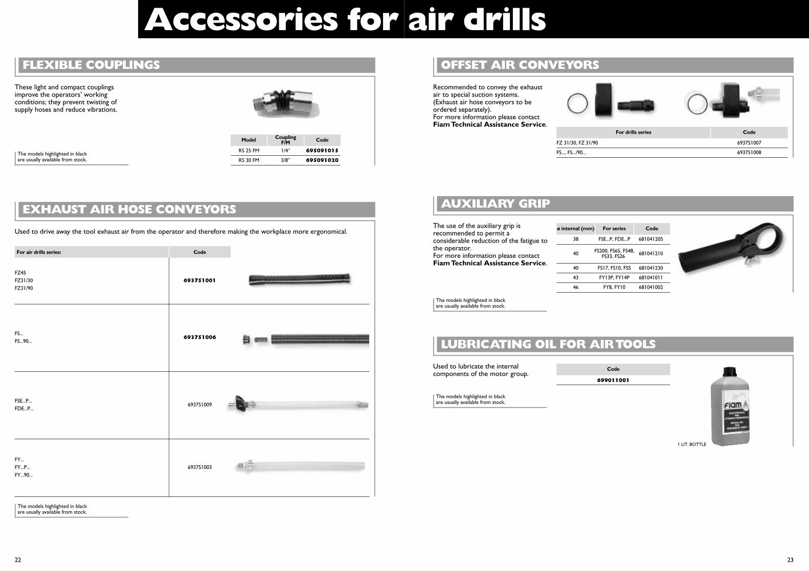
FLEXIBLE COUPLINGS
These light and compact couplingsimprove the operators’ workingconditions; they prevent twisting ofsupply hoses and reduce vibrations.
FZ 31/30, FZ 31/90
FS..., FS.../90...
693751007
693751008
OFFSET AIR CONVEYORS
Recommended to convey the exhaustair to special suction systems.(Exhaust air hose conveyors to beordered separately).For more information please contactFiam Technical Assistance Service.
For drills series Code
AUXILIARY GRIP
The use of the auxiliary grip isrecommended to permit aconsiderable reduction of the fatigue tothe operator.For more information please contactFiam Technical Assistance Service.
699011001
Code
LUBRICATING OIL FOR AIR TOOLS
Used to lubricate the internalcomponents of the motor group.
EXHAUST AIR HOSE CONVEYORS
Used to drive away the tool exhaust air from the operator and therefore making the workplace more ergonomical.
RS 25 FM 1/4” 695091015
RS 30 FM 3/8” 695091020
Model CouplingF/M Code
CodeFor air drills series:
693751001FZ45FZ31/30FZ31/90
FS...FS...90...
FSE...P...FDE...P...
FY...FY...P...FY...90...
693751003
693751006
693751009
1 LIT. BOTTLE
The models highlighted in blackare usually available from stock.
The models highlighted in blackare usually available from stock.
The models highlighted in blackare usually available from stock.
The models highlighted in blackare usually available from stock.
38 FSE...P, FDE...P 681041205
40 681041210
40 FS17, FS10, FS5 681041230
43 FY13P, FY14P 681041011
46 FY8, FY10 681041002
FS200, FS65, FS48,FS33, FS26
ø internal (mm) For series Code
Accessories for air drills
24 25
BALANCER
The use of the balancer allows theoperator to work in safety and withouteffort, at the same time guaranteeingthe maximum care of the tool.
0,4÷1 1600 690011160
1÷2 1600 690021160
2÷4 2000 690041200
4÷6 2000 690061200
6÷8 2000 690081200
8÷10 2500 690101250
Capacitymin - max
Cable lengthmm Code
In conformity with MachineDirectives (Law 89/392/EEC and Sup.)
BALANCER WITH BUILT-IN SUPPLY HOSE
Particularly indicated to support and tofeed at the same time straight air tools.The balancer is provided with a hosethat can be connected directly to themain air feed so that the tool issupplied directly.
1,2÷2,5 1350 1/4” gas 691021202
Capacitymin - max
Lengthmm
Malecoupling Code
BA10 BALANCING ARM
The BA10 balancing arm is ideal whenworking at the bench. It suspends thetool in the required position fortightening, drilling, tapping, etc. with notorque reaction on the operator’shand. This makes work safer and morecomfortable, without fatigue.
Balancing arm BA10 692031002
Model Code
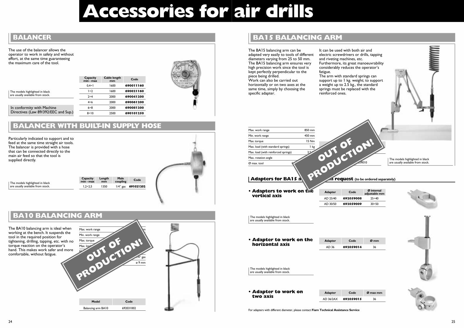
BA15 BALANCING ARM
Adapters for BA15 available upon request (to be ordered separately)
The BA15 balancing arm can beadapted very easily to tools of differentdiameters varying from 25 to 50 mm.The BA15 balancing arm ensures veryhigh precision work since the tool iskept perfectly perpendicular to thepiece being drilled.Work can also be carried outhorizontally or on two axes at thesame time, simply by choosing thespecific adapter.
• Adapters to work on thevertical axis
BA15 balancing arm 692031009
Model Code
Max. work range 850 mm
Min. work range 450 mm
Max. torque 15 Nm
Max. load (with standard springs) 1 kg
Max. load (with reinforced springs) 2.5 kg
Max. rotation angle 360°
Ø max. tool from 25 to 50 mm
AD 25/40 692059008 25÷40
AD 30/50 692059009 30÷50
Adapter Code Ø internaladjustable mm
• Adapter to work on thehorizontal axis
AD 36 692059014 36
Adapter Code Ø mm
• Adapter to work ontwo axis
AD 36/2AX 692059015 36
Adapter Code Ø max mm
It can be used with both air andelectric screwdrivers or drills, tappingand riveting machines, etc.Furthermore, its great manoeuvrabilityconsiderably reduces the operator’sfatigue.The arm with standard springs cansupport up to 1 kg. weight; to supporta weight up to 2.5 kg., the standardsprings must be replaced with thereinforced ones.
For adapters with different diameter, please contact Fiam Technical Assistance Service
The models highlighted in blackare usually available from stock.
The models highlighted in blackare usually available from stock.
The models highlighted in blackare usually available from stock.
The models highlighted in blackare usually available from stock.
The models highlighted in blackare usually available from stock.
Max. work range 450 mm
Min. work range 300 mm
Max. torque 10 Nm
Max. load 1,6 kg
Max. rotation angle 360°
Air inlet 1/4” gas
Recommended hose bore ø 9 mm
Standard equipment• Reinforced spring code 692059010
OUT OF
PRODUCTION!
OUT OF
PRODUCTION!
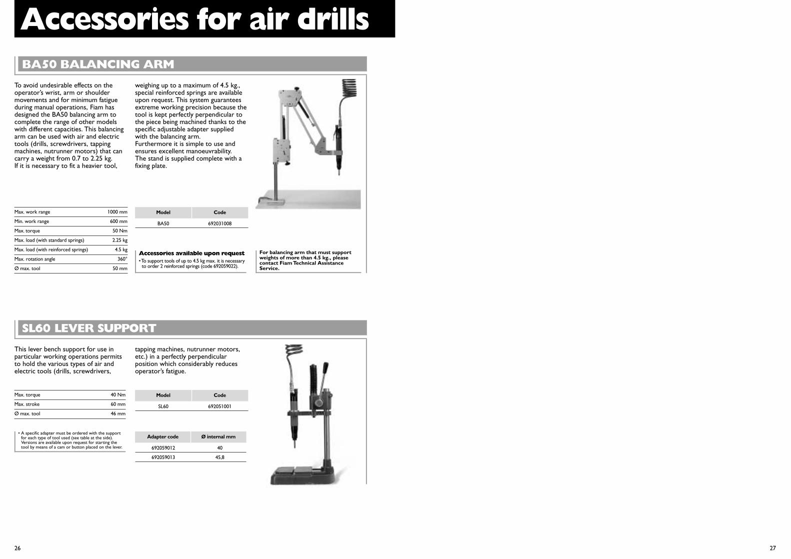
Accessories for air drillsBA50 BALANCING ARM
To avoid undesirable effects on theoperator’s wrist, arm or shouldermovements and for minimum fatigueduring manual operations, Fiam hasdesigned the BA50 balancing arm tocomplete the range of other modelswith different capacities. This balancingarm can be used with air and electrictools (drills, screwdrivers, tappingmachines, nutrunner motors) that cancarry a weight from 0.7 to 2.25 kg.If it is necessary to fit a heavier tool,
weighing up to a maximum of 4.5 kg.,special reinforced springs are availableupon request. This system guaranteesextreme working precision because thetool is kept perfectly perpendicular tothe piece being machined thanks to thespecific adjustable adapter suppliedwith the balancing arm.Furthermore it is simple to use andensures excellent manoeuvrability.The stand is supplied complete with afixing plate.
Accessories available upon request• To support tools of up to 4.5 kg max. it is necessary
to order 2 reinforced springs (code 692059022).
BA50 692031008
Model CodeMax. work range 1000 mm
Min. work range 600 mm
Max. torque 50 Nm
Max. load (with standard springs) 2.25 kg
Max. load (with reinforced springs) 4.5 kg
Max. rotation angle 360°
Ø max. tool 50 mm
For balancing arm that must supportweights of more than 4.5 kg., pleasecontact Fiam Technical AssistanceService.
26 27
SL60 LEVER SUPPORT
This lever bench support for use inparticular working operations permitsto hold the various types of air andelectric tools (drills, screwdrivers,
• A specific adapter must be ordered with the supportfor each type of tool used (see table at the side).Versions are available upon request for starting thetool by means of a cam or button placed on the lever.
SL60 692051001
Model CodeMax. torque 40 Nm
Max. stroke 60 mm
Ø max. tool 46 mm
tapping machines, nutrunner motors,etc.) in a perfectly perpendicularposition which considerably reducesoperator’s fatigue.
692059012 40
692059013 45,8
Adapter code Ø internal mm

•• Drilling capacity:from 1 to 20 mm Ø
• Type of grip:straight, pistol andangle models
Air drillsAir
dri
lls
and
tap
pers
INDUSTRIAL AIR TOOLSJuly
200
0 -
34
Pri
nted
on
recy
cled
pap
er fo
r th
e sa
fegu
ard
of t
he e
nvir
onm
ent
INDUSTRIAL AIR TOOLS Quality CertificationUNI EN ISO 9001 / ICIM 0250
Environmental Management System CertificateUNI EN ISO 14001 / ICIM 0002A/0
Fiam Utensili Pneumatici spaViale Crispi, 123 - 36100 Vicenza / ItalyTel. +39.0444.562611 - Fax +39.0444.562325customerservice@fiamairtools.comwww.fiamairtools.com