Embed Size (px)
Citation preview
1
Installation & Operating Instructions
INSTALLATION & OPERATING INSTRUCTIONS
520300.501520310.501520315.501520315.506520315.701520315.706520316.301520316.306520316.501520316.506520316.701
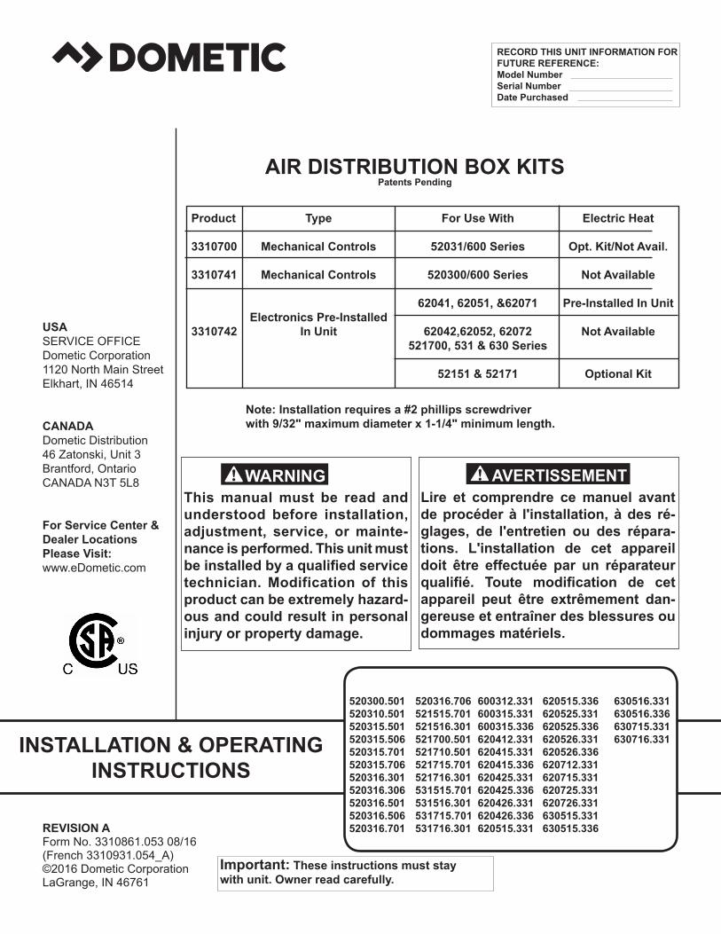
AIR DISTRIBUTION BOX KITSPatents Pending
This manual must be read and understood before installation, adjustment, service, or mainte-nance is performed. This unit must be installed by a qualified service technician. Modification of this product can be extremely hazard-ous and could result in personal injury or property damage.
Lire et comprendre ce manuel avant de procéder à l'installation, à des ré-glages, de l'entretien ou des répara-tions. L'installation de cet appareil doit être effectuée par un réparateur qualifié. Toute modification de cet appareil peut être extrêmement dan-gereuse et entraîner des blessures ou dommages matériels.
REVISION AForm No. 3310861.053 08/16(French 3310931.054_A)©2016 Dometic CorporationLaGrange, IN 46761
Important: These instructions must stay with unit. Owner read carefully.
RECORD THIS UNIT INFORMATION FOR FUTURE REFERENCE:Model NumberSerial NumberDate Purchased
USASERVICE OFFICEDometic Corporation1120 North Main StreetElkhart, IN 46514
CANADADometic Distribution46 Zatonski, Unit 3Brantford, OntarioCANADA N3T 5L8
For Service Center &Dealer LocationsPlease Visit:www.eDometic.com
Product Type For Use With Electric Heat
3310700 Mechanical Controls 52031/600 Series Opt. Kit/Not Avail.
3310741 Mechanical Controls 520300/600 Series Not Available
62041, 62051, &62071 Pre-Installed In Unit Electronics Pre-Installed 3310742 In Unit 62042,62052, 62072 Not Available 521700, 531 & 630 Series 52151 & 52171 Optional Kit
Note: Installation requires a #2 phillips screwdriver with 9/32" maximum diameter x 1-1/4" minimum length.
520316.706521515.701521516.301521700.501521710.501521715.701521716.301531515.701 531516.301531715.701 531716.301
600312.331600315.331600315.336620412.331620415.331620415.336620425.331620425.336620426.331620426.336620515.331
620515.336620525.331620525.336620526.331620526.336620712.331620715.331620725.331620726.331630515.331630515.336
630516.331630516.336630715.331630716.331
2
Installation & Operating Instructions
GENERAL INFORMATIONA. This air conditioner is designed for: 1. Installation on a recreational vehicle during or af-
ter the time the vehicle is manufactured. 2. Mounting on the roof of a recreational vehicle. 3. Roof construction with rafters/joists on minimum
of 16 inch centers. 4. Minimum of 1.00 inch and maximum of 5.5 inches
distance between roof to ceiling of recreational vehicle.
B. The ability of the air conditioner to maintain the de-
sired inside temperature depends on the heat gain of the RV. Some preventative measures taken by the occupants of the RV can reduce the heat gain and im-prove the performance of the air conditioner. During extremely high outdoor temperatures, the heat gain of the vehicle may be reduced by:
1. Parking the RV in a shaded area 2. Using window shades (blinds and/or curtains) 3. Keeping windows and doors shut or minimizing
usage 4. Avoiding the use of heat producing appliances
Operation on High Fan/Cooling mode will give optimum or maximum efficiency in high humidity or high outside temperature.
Starting the air conditioner early in the morning and giving it a "head start" on the expected high outdoor ambient will greatly improve its ability to maintain the desired indoor temperature.
For a more permanent solution to a high heat gain, accessories like A&E outdoor patio and win-dow awnings will reduce heat gain by removing the direct exposure to the sun. They also add a nice area to enjoy company during the cool of the evening.
C. Condensation
Note: The manufacturer of this air conditioner will not be responsible for damage caused by condensed moisture on ceilings or other surfaces. Air contains moisture and this moisture tends to condense on cold surfaces. When air enters the RV, condensed moisture may appear on the ceiling, windows, metal parts, etc. The air conditioner removes this moisture from the air during normal opera-tion. Keeping doors and windows closed when this air conditioner is in operation will minimize condensed mois-ture on cold surfaces.
SAFETY INSTRUCTIONS
This manual has safety information and instruc-tions to help users eliminate or reduce the risk of accidents and injuries.
RECOGNIZE SAFETY INFORMATION
This is the safety-alert symbol. When you see this symbol in this manual, be alert to the potential for personal injury.
Follow recommended precautions and safe op-erating instructions.UNDERSTAND SIGNAL WORDS
A signal word , WARNING OR CAUTION is used with the safety-alert symbol. They give the level of risk for potential injury.
indicates a potentially hazard-ous situation which, if not avoided, could result in death or serious injury.
indicates a potentially hazard-ous situation which, if not avoided may result in minor or moderate injury.
used without the safety alert symbol indicates, a potentially hazardous situa-tion which, if not avoided may result in property damage.
Read and follow all safety information and in-structions.
WARNING!
CAUTION
CAUTION!
3
Installation & Operating Instructions
MO
DEL
N
OM
INA
L EL
ECTR
ICA
L C
OM
PRES
SOR
C
OM
PRES
SOR
FA
N M
OTO
R
FAN
MO
TOR
SC
FM-H
IGH
R
EFR
IGER
AN
T M
INIM
UM
A
C C
IRC
UIT
IN
STA
LLED
MIN
IMU
M
NO
. C
APA
CIT
Y R
ATIN
G
RAT
ED L
OA
D
LOC
KED
R
ATED
LO
AD
LO
CK
ED
SPEE
D
R-2
2 (O
Z)
W
IRE
SIZE
* PR
OTE
CTI
ON
W
EIG
HT
G
ENER
ATO
R
(BTU
/HR
)
AM
PS
RO
TOR
A
MPS
R
OTO
R
MA
X
**
* USE
R
(PO
UN
DS)
SIZE
**
C
OO
LIN
G
AM
PS
A
MPS
SUPP
LIED
1
UN
IT/2
UN
ITS
52
0300
.501
N
/A
7.
8 49
.0
3.0
8.5
375
20.0
15
Am
p 89
2.
4 K
W /
4.0
KW
5203
10.5
01
9,00
0
7.8
49.0
3.
0 8.
5 37
5 20
.0
20 A
mp
89
2.4
KW
/ 4.
0 K
W52
0315
.501
13
,500
10.3
62
.0
3.0
8.5
375
16.5
20
Am
p 91
3.
5 K
W /
5.0
KW
5203
15.5
06
13,5
00
10
.3
62.0
3.
0 8.
5 37
5 16
.5
20 A
mp
91
3.5
KW
/ 5.
0 K
W52
0315
.701
13
,500
12.0
58
.0
3.0
8.5
375
16.5
20
Am
p 91
3.
5 K
W /
5.0
KW
5203
15.7
06
13,5
00
12
.0
58.0
3.
0 8.
5 37
5 16
.5
20 A
mp
91
3.5
KW
/ 5.
0 K
W52
0316
.301
15
,000
13.2
60
.0
2.8
7.6
375
30.0
20
Am
p 10
5 3.
5 K
W /
5.0
KW
5203
16.3
06
15,0
00
13
.2
60.0
2.
8 7.
6 37
5 30
.0
20 A
mp
105
3.5
KW
/ 5.
0 K
W52
0316
.501
15
,000
13.2
79
2.
8 7.
6 37
5 30
.0
20 A
mp
105
3.5
KW
/ 5.
0 K
W52
0316
.506
15
,000
13.2
79
2.
8 7.
6 37
5 30
.0
20 A
mp
105
3.5
KW
/ 5.
0 K
W
5203
16.7
01
15,0
00
12
.6
62.0
2.
65
7.6
375
30.0
20
Am
p 10
5 3.
5 K
W /
5.0
KW
5203
16.7
06
15,0
00
12
.6
62.0
2.
65
7.6
375
30.0
20
Am
p 10
5 3.
5 K
W /
5.0
KW
5215
15.7
01
13,5
00
12
.0
58.0
3.
0 8.
5 37
5
16.5
20
Am
p 92
3.
5 K
W /
5.0
KW
5215
16.3
01
15,0
00
13
.2
60.0
2.
8 7.
6 37
5
30.0
20
Am
p 10
6 3.
5 K
W /
5.0
KW
5217
00.5
01
N/A
7.8
49.0
3.
0 8.
5 35
0 20
.0
15 A
mp
90
2.4
KW
/ 4.
0 K
W52
1710
.501
9,
000
7.
8 49
.0
3.0
8.5
350
20.0
20
Am
p 90
2.
4 K
W /
4.0
KW
5217
15.7
01
13,5
00
12
.0
58.0
3.
0 8.
5 35
0 16
.5
20 A
mp
92
3.5
KW
/ 5.
0 K
W52
1716
.301
15
,000
13.2
60
.0
2.8
7.6
375
30.0
20
Am
p 10
6 3.
5 K
W /
5.0
KW
5315
15.7
01
13,5
00
12
.2
58.0
3.
0 8.
5 37
5 17
.5
20 A
mp
93
3.5
KW
/ 5.
0 K
W53
1516
.301
15
,000
13.2
60
.0
2.8
7.6
375
29
.5
20 A
mp
107
3.5
KW
/ 5.
0 K
W53
1715
.701
13
,500
12.2
58
.0
3.0
8.5
375
17.5
20
Am
p 93
3.
5 K
W /
5.0
KW
5317
16.3
01
15,0
00
13
.2
60.0
2.
8 7.
6 37
5 29
.5
20 A
mp
107
3.5
KW
/ 5.
0 K
W60
0312
.331
11
,000
9.5
53.0
2.
8 8.
8 37
5 17
.0
20 A
mp
95
2.5
KW
/ 4.
0 K
W60
0315
.331
13
,500
12.4
60
.0
3.1
8.8
375
15.2
20
Am
p 95
3.
5 K
W /
5.0
KW
6003
15.3
36
13,5
00
12
.4
60.0
3.
1 8.
8 37
5 15
.2
20 A
mp
95
3.5
KW
/ 5.
0 K
W62
0412
.331
11
,000
9.5
53.0
3.
1 8.
8 33
5 16
.5
20 A
mp
95
2.5
KW
/ 4.
0 K
W62
0415
.331
13
,500
12.4
60
.0
3.1
8.8
335
15.5
20
Am
p 95
3.
5 K
W /
5.0
KW
6204
15.3
36
13,5
00
12
.4
60.0
3.
1 8.
8 33
5 15
.5
20 A
mp
95
3.5
KW
/ 5.
0 K
W62
0425
.331
13
,500
12.4
60
.0
3.1
8.8
335
15.5
20
Am
p 95
3.
5 K
W /
5.0
KW
6204
25.3
36
13,5
00
12
.4
60.0
3.
1 8.
8 33
5 15
.5
20 A
mp
95
3.5
KW
/ 5.
0 K
W62
0426
.331
15
,000
12.0
64
.0
3.3
8.5
380
21.5
20
Am
p 10
4 3.
5 K
W /
5.0
KW
6204
26.3
36
15,0
00
12
.0
64.0
3.
3 8.
5 38
0 21
.5
20 A
mp
104
3.5
KW
/ 5.
0 K
W62
0515
.331
13
.500
12.4
60
.0
3.5
10.0
33
5 16
.5
20 A
mp
95
3.5
KW
/ 5.
0 K
W62
0515
.336
13
,500
12.4
60
.0
3.5
10.0
33
5 16
.5
20 A
mp
95
3.5
KW
/ 5.
0 K
W
SPEC
IFIC
ATIO
NS
120
VAC
,60
HZ.
, 1PH
.
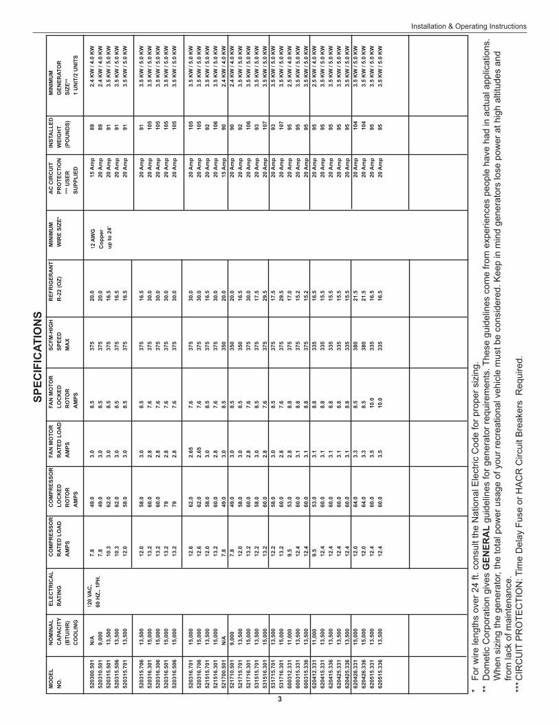
* Fo
r wire
leng
ths
over
24
ft. c
onsu
lt th
e N
atio
nal E
lect
ric C
ode
for p
rope
r siz
ing.
** D
omet
ic C
orpo
ratio
n gi
ves
GEN
ERA
L gu
idel
ines
for g
ener
ator
requ
irem
ents
. The
se g
uide
lines
com
e fro
m e
xper
ienc
es p
eopl
e ha
ve h
ad in
act
ual a
pplic
atio
ns.
Whe
n si
zing
the
gene
rato
r, th
e to
tal p
ower
usa
ge o
f you
r rec
reat
iona
l veh
icle
mus
t be
cons
ider
ed. K
eep
in m
ind
gene
rato
rs lo
se p
ower
at h
igh
altit
udes
and
fro
m la
ck o
f mai
nten
ance
.**
* CIR
CU
IT P
RO
TEC
TIO
N: T
ime
Del
ay F
use
or H
AC
R C
ircui
t Bre
aker
s R
equi
red.
12 A
WG
Cop
per
up to
24’
4
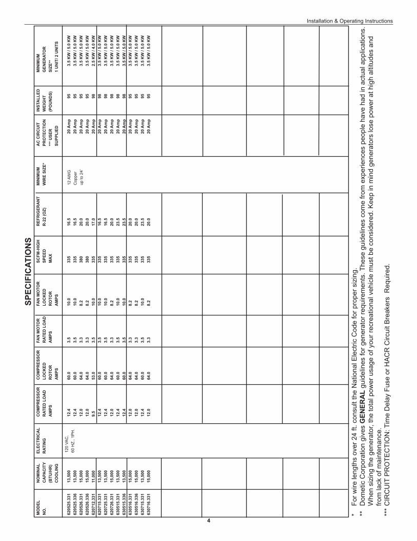
Installation & Operating InstructionsSP
ECIF
ICAT
ION
S
120
VAC
,60
HZ.
, 1P
H.
12 A
WG
Cop
per
up to
24’
* Fo
r wire
leng
ths
over
24
ft. c
onsu
lt th
e N
atio
nal E
lect
ric C
ode
for p
rope
r siz
ing.
**
Dom
etic
Cor
pora
tion
give
s G
ENER
AL
guid
elin
es fo
r gen
erat
or re
quire
men
ts. T
hese
gui
delin
es c
ome
from
exp
erie
nces
peo
ple
have
had
in a
ctua
l app
licat
ions
. W
hen
sizi
ng th
e ge
nera
tor,
the
tota
l pow
er u
sage
of y
our r
ecre
atio
nal v
ehic
le m
ust b
e co
nsid
ered
. Kee
p in
min
d ge
nera
tors
lose
pow
er a
t hig
h al
titud
es a
nd
from
lack
of m
aint
enan
ce.
***
CIR
CU
IT P
RO
TEC
TIO
N: T
ime
Del
ay F
use
or H
AC
R C
ircui
t Bre
aker
s R
equi
red.
MO
DEL
N
OM
INA
L EL
ECTR
ICA
L C
OM
PRES
SOR
C
OM
PRES
SOR
FA
N M
OTO
R
FAN
MO
TOR
SC
FM-H
IGH
R
EFR
IGER
AN
T M
INIM
UM
A
C C
IRC
UIT
IN
STA
LLED
MIN
IMU
MN
O.
CA
PAC
ITY
RAT
ING
R
ATED
LO
AD
LO
CK
ED
RAT
ED L
OA
D
LOC
KED
SP
EED
R
-22
(OZ)
WIR
E SI
ZE*
PRO
TEC
TIO
N
WEI
GH
T
GEN
ERAT
OR
(B
TU/H
R)
A
MPS
R
OTO
R
AM
PS
RO
TOR
M
AX
*** U
SER
(P
OU
ND
S)
SI
ZE**
CO
OLI
NG
A
MPS
AM
PS
SU
PPLI
ED
1 U
NIT
/ 2 U
NIT
S
6205
25.3
31
13,5
00
12
.4
60.0
3.
5 10
.0
335
16.5
20
Am
p 95
3.
5 K
W /
5.0
KW
6205
25.3
36
13,5
00
12
.4
60.0
3.
5 10
.0
335
16.5
20
Am
p 95
3.
5 K
W /
5.0
KW
6205
26.3
31
15,0
00
12
.0
64.0
3.
3 8.
2 38
0 20
.0
20 A
mp
95
3.5
KW
/ 5.
0 K
W62
0526
.336
15
,000
12.0
64
.0
3.3
8.2
380
20.0
20
Am
p 95
3.
5 K
W /
5.0
KW
6207
12.3
31
11,0
00
9.
5 53
.0
3.5
10.0
33
5 17
.0
20 A
mp
98
2.5
KW
/ 4.
0 K
W62
0715
.331
13
,500
12.4
60
.0
3.5
10.0
33
5 16
.5
20 A
mp
98
3.5
KW
/ 5.
0 K
W62
0725
.331
13
,500
12.4
60
.0
3.5
10.0
33
5 16
.5
20 A
mp
98
3.5
KW
/ 5.
0 K
W62
0726
.331
15
,000
12.0
64
.0
3.3
8.2
335
20.0
20
Am
p 98
3.
5 K
W /
5.0
KW
6305
15.3
31
13,5
00
12
.4
60.0
3.
5 10
.0
335
23.5
20
Am
p 98
3.
5 K
W /
5.0
KW
6305
15.3
36
13,5
00
12
.4
60.0
3.
5 10
.0
335
23.5
20
Am
p 98
3.
5 K
W /
5.0
KW
6305
16.3
31
15,0
00
12
.0
64.0
3.
3 8.
2 33
5 20
.0
20 A
mp
95
3.5
KW
/ 5.
0 K
W63
0516
.336
15
,000
12.0
64
.0
3.3
8.2
335
20.0
20
Am
p 95
3.
5 K
W /
5.0
KW
6307
15.3
31
13,5
00
12
.4
60.0
3.
5 10
.0
335
23.5
20
Am
p 95
3.
5 K
W /
5.0
KW
6307
16.3
31
15,0
00
12
.0
64.0
3.
3 8.
2 33
5 20
.0
20 A
mp
95
3.5
KW
/ 5.
0 K
W
5
Installation & Operating Instructions
A. Precautions
INSTALLATION INSTRUCTIONS
Personal Injury Hazard. Failure to follow these installation instructions may cause serious personal injury and/or property damage. 1. Read installation and operating instructions care-
fully before attempting to start your air conditioner installation.
2. Dometic Corporation will not be liable for any damages or injury incurred due to failure in fol-lowing these instructions.
3. Installation must comply with NFPA 70: National Electrical Code regulations and any State or Lo-cal Codes or regulations.
4. DO NOT add any devices or accessories to this air conditioner except those specifically autho-rized in writing by Dometic.
5. This equipment must be serviced by qualified personnel and some states require these people to be licensed.
A. Choosing Location For The Air Condi-tioner
This air conditioner is specifically designed for instal-lation on the roof of a recreational vehicle (RV). The roof must support 130 pounds when the RV is in mo-tion. Normally a 200 lb. static load design will meet this requirement. Insure the roof will support the ap-pliance and the installer personnel.
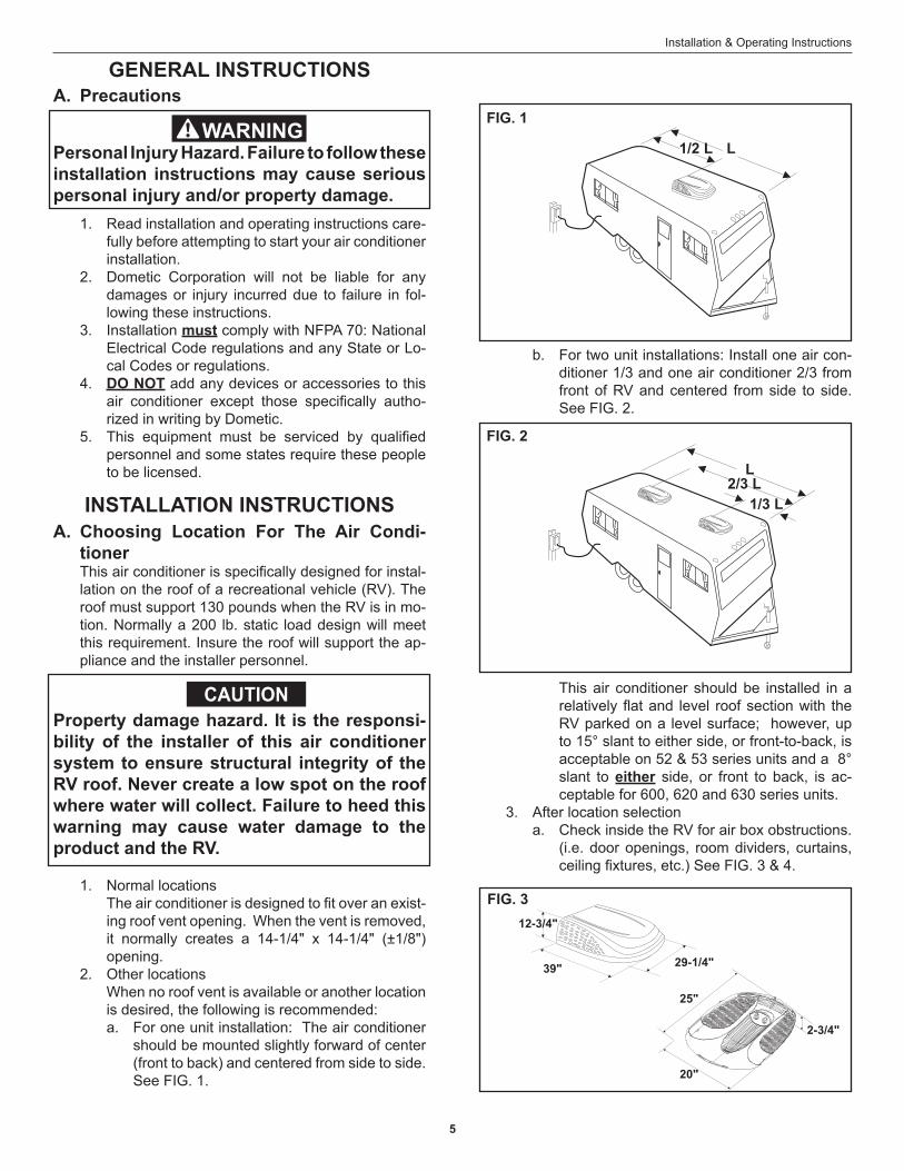
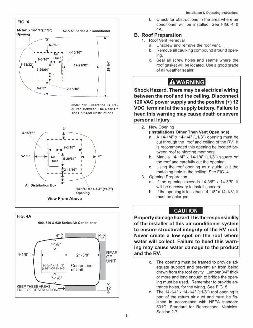
b. For two unit installations: Install one air con-ditioner 1/3 and one air conditioner 2/3 from front of RV and centered from side to side. See FIG. 2.
Property damage hazard. It is the responsi-bility of the installer of this air conditioner system to ensure structural integrity of the RV roof. Never create a low spot on the roof where water will collect. Failure to heed this warning may cause water damage to the product and the RV.
1. Normal locations The air conditioner is designed to fit over an exist-
ing roof vent opening. When the vent is removed, it normally creates a 14-1/4" x 14-1/4" (±1/8") opening.
2. Other locations When no roof vent is available or another location
is desired, the following is recommended:a. For one unit installation: The air conditioner
should be mounted slightly forward of center (front to back) and centered from side to side. See FIG. 1.
FIG. 1
1/2 L L
FIG. 2
L2/3 L
1/3 L
This air conditioner should be installed in a relatively flat and level roof section with the RV parked on a level surface; however, up to 15° slant to either side, or front-to-back, is acceptable on 52 & 53 series units and a 8° slant to either side, or front to back, is ac-ceptable for 600, 620 and 630 series units.
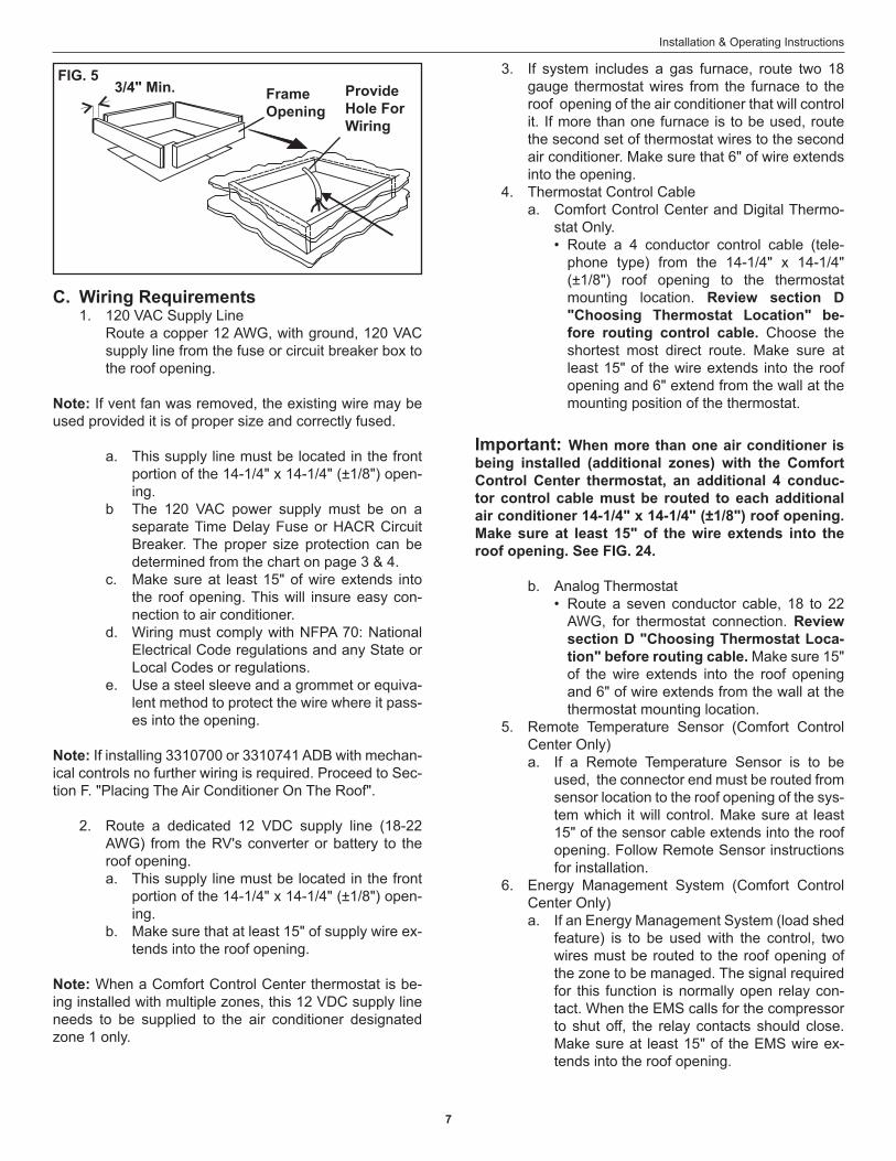
3. After location selectiona. Check inside the RV for air box obstructions.
(i.e. door openings, room dividers, curtains, ceiling fixtures, etc.) See FIG. 3 & 4.
2-3/4"
20"
25"
12-3/4"
29-1/4"39"
FIG. 3
GENERAL INSTRUCTIONS
CAUTION
6
Installation & Operating Instructions
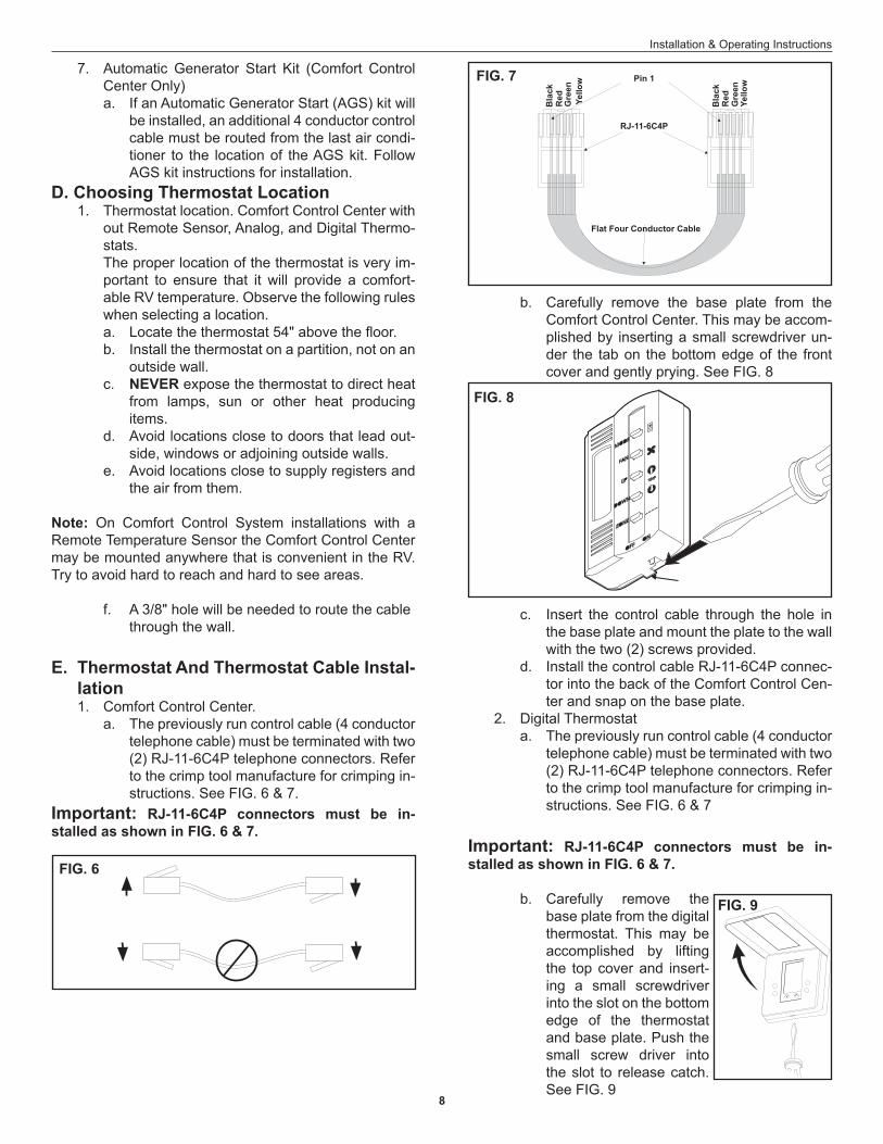
b. Check for obstructions in the area where air conditioner will be installed. See FIG. 4 & 4A.
B. Roof Preparation 1. Roof Vent Removal
a. Unscrew and remove the roof vent.b. Remove all caulking compound around open-
ing.c. Seal all screw holes and seams where the
roof gasket will be located. Use a good grade of all weather sealer.
Shock Hazard. There may be electrical wiring between the roof and the ceiling. Disconnect 120 VAC power supply and the positive (+) 12 VDC terminal at the supply battery. Failure to heed this warning may cause death or severe personal injury.
600, 620 & 630 Series Air Conditioner
FIG. 4A
2. New Opening(Installations Other Then Vent Openings)a. A 14-1/4" x 14-1/4" (±1/8") opening must be
cut through the roof and ceiling of the RV. It is recommended this opening be located be-tween roof reinforcing members.
b. Mark a 14-1/4" x 14-1/4" (±1/8") square on the roof and carefully cut the opening.
c. Using the roof opening as a guide, cut the matching hole in the ceiling. See FIG. 4.
3. Opening Preparationa. If the opening exceeds 14-3/8" x 14-3/8", it
will be necessary to install spacers.b. If the opening is less than 14-1/8" x 14-1/8", it
must be enlarged.
Property damage hazard. It is the responsibility of the installer of this air conditioner system to ensure structural integrity of the RV roof. Never create a low spot on the roof where water will collect. Failure to heed this warn-ing may cause water damage to the product and the RV.
c. The opening must be framed to provide ad-equate support and prevent air from being drawn from the roof cavity. Lumber 3/4" thick or more and long enough to bridge the open-ing must be used. Remember to provide en-trance holes, for the wiring. See FIG. 5.
d. The 14-1/4" x 14-1/4" (±1/8") roof opening is part of the return air duct and must be fin-ished in accordance with NFPA standard 501C, Standard for Recreational Vehicles, Section 2-7.
FIG. 4
6-7/8"
14-1/4" x 14-1/4"(±1/8")Opening
6-7/8" 2-15/16"
4-15/16"
5-29/64"17-21/32"
29-1
/4"
7-13/32"
Note: 18" Clearance Is Re-quired Between The Rear Of The Unit And Obstructions
14-1/4" x 14-1/4" (±1/8")Opening
3"
3"
5-29/64"
2-15/16"
4-15/16"
9-3/16"
9-3/16"
52 & 53 Series Air Conditioner
Air Distribution Box
AirDuct
AirDuct
5-1/8" 6"
View From Above
CAUTION
7
Installation & Operating Instructions
C. Wiring Requirements 1. 120 VAC Supply Line Route a copper 12 AWG, with ground, 120 VAC
supply line from the fuse or circuit breaker box to the roof opening.
Note: If vent fan was removed, the existing wire may be used provided it is of proper size and correctly fused.
a. This supply line must be located in the front portion of the 14-1/4" x 14-1/4" (±1/8") open-ing.
b The 120 VAC power supply must be on a separate Time Delay Fuse or HACR Circuit Breaker. The proper size protection can be determined from the chart on page 3 & 4.
c. Make sure at least 15" of wire extends into the roof opening. This will insure easy con-nection to air conditioner.
d. Wiring must comply with NFPA 70: National Electrical Code regulations and any State or Local Codes or regulations.
e. Use a steel sleeve and a grommet or equiva-lent method to protect the wire where it pass-es into the opening.
Note: If installing 3310700 or 3310741 ADB with mechan-ical controls no further wiring is required. Proceed to Sec-tion F. "Placing The Air Conditioner On The Roof".
2. Route a dedicated 12 VDC supply line (18-22 AWG) from the RV's converter or battery to the roof opening.a. This supply line must be located in the front
portion of the 14-1/4" x 14-1/4" (±1/8") open-ing.
b. Make sure that at least 15" of supply wire ex-tends into the roof opening.
Note: When a Comfort Control Center thermostat is be-ing installed with multiple zones, this 12 VDC supply line needs to be supplied to the air conditioner designated zone 1 only.
3. If system includes a gas furnace, route two 18 gauge thermostat wires from the furnace to the roof opening of the air conditioner that will control it. If more than one furnace is to be used, route the second set of thermostat wires to the second air conditioner. Make sure that 6" of wire extends into the opening.
4. Thermostat Control Cablea. Comfort Control Center and Digital Thermo-
stat Only. • Route a 4 conductor control cable (tele-
phone type) from the 14-1/4" x 14-1/4" (±1/8") roof opening to the thermostat mounting location. Review section D "Choosing Thermostat Location" be-fore routing control cable. Choose the shortest most direct route. Make sure at least 15" of the wire extends into the roof opening and 6" extend from the wall at the mounting position of the thermostat.
Important: When more than one air conditioner is being installed (additional zones) with the Comfort Control Center thermostat, an additional 4 conduc-tor control cable must be routed to each additional air conditioner 14-1/4" x 14-1/4" (±1/8") roof opening. Make sure at least 15" of the wire extends into the roof opening. See FIG. 24.
b. Analog Thermostat• Route a seven conductor cable, 18 to 22
AWG, for thermostat connection. Review section D "Choosing Thermostat Loca-tion" before routing cable. Make sure 15" of the wire extends into the roof opening and 6" of wire extends from the wall at the thermostat mounting location.
5. Remote Temperature Sensor (Comfort Control Center Only)a. If a Remote Temperature Sensor is to be
used, the connector end must be routed from sensor location to the roof opening of the sys-tem which it will control. Make sure at least 15" of the sensor cable extends into the roof opening. Follow Remote Sensor instructions for installation.
6. Energy Management System (Comfort Control Center Only)a. If an Energy Management System (load shed
feature) is to be used with the control, two wires must be routed to the roof opening of the zone to be managed. The signal required for this function is normally open relay con-tact. When the EMS calls for the compressor to shut off, the relay contacts should close. Make sure at least 15" of the EMS wire ex-tends into the roof opening.
FIG. 53/4" Min. Frame
OpeningProvide Hole For Wiring
8
Installation & Operating Instructions
7. Automatic Generator Start Kit (Comfort Control Center Only)a. If an Automatic Generator Start (AGS) kit will
be installed, an additional 4 conductor control cable must be routed from the last air condi-tioner to the location of the AGS kit. Follow AGS kit instructions for installation.
D. Choosing Thermostat Location 1. Thermostat location. Comfort Control Center with
out Remote Sensor, Analog, and Digital Thermo-stats.
The proper location of the thermostat is very im-portant to ensure that it will provide a comfort-able RV temperature. Observe the following rules when selecting a location.a. Locate the thermostat 54" above the floor.b. Install the thermostat on a partition, not on an
outside wall.c. NEVER expose the thermostat to direct heat
from lamps, sun or other heat producing items.
d. Avoid locations close to doors that lead out-side, windows or adjoining outside walls.
e. Avoid locations close to supply registers and the air from them.
Note: On Comfort Control System installations with a Remote Temperature Sensor the Comfort Control Center may be mounted anywhere that is convenient in the RV. Try to avoid hard to reach and hard to see areas.
f. A 3/8" hole will be needed to route the cable through the wall.
E. Thermostat And Thermostat Cable Instal-lation
1. Comfort Control Center. a. The previously run control cable (4 conductor
telephone cable) must be terminated with two (2) RJ-11-6C4P telephone connectors. Refer to the crimp tool manufacture for crimping in-structions. See FIG. 6 & 7.
Important: RJ-11-6C4P connectors must be in-stalled as shown in FIG. 6 & 7.
b. Carefully remove the base plate from the Comfort Control Center. This may be accom-plished by inserting a small screwdriver un-der the tab on the bottom edge of the front cover and gently prying. See FIG. 8
c. Insert the control cable through the hole in the base plate and mount the plate to the wall with the two (2) screws provided.
d. Install the control cable RJ-11-6C4P connec-tor into the back of the Comfort Control Cen-ter and snap on the base plate.
2. Digital Thermostata. The previously run control cable (4 conductor
telephone cable) must be terminated with two (2) RJ-11-6C4P telephone connectors. Refer to the crimp tool manufacture for crimping in-structions. See FIG. 6 & 7
Important: RJ-11-6C4P connectors must be in-stalled as shown in FIG. 6 & 7.
b. Carefully remove the base plate from the digital thermostat. This may be accomplished by lifting the top cover and insert-ing a small screwdriver into the slot on the bottom edge of the thermostat and base plate. Push the small screw driver into the slot to release catch. See FIG. 9
FIG. 6
FIG. 8
FIG. 9
FIG. 7
Flat Four Conductor Cable
RJ-11-6C4P
Pin 1
Bla
ck
Bla
ckR
ed
Red
Gre
en
Gre
en
Yello
w
Yello
w
9
Installation & Operating Instructions
c. Install the control cable through the hole in the base plate and mount the plate to the wall with the two (2) screws provided. Check the alignment to ensure level installation.
d. Install the control cable RJ-11-6C4P connec-tor into the back of the thermostat and snap on the base plate.
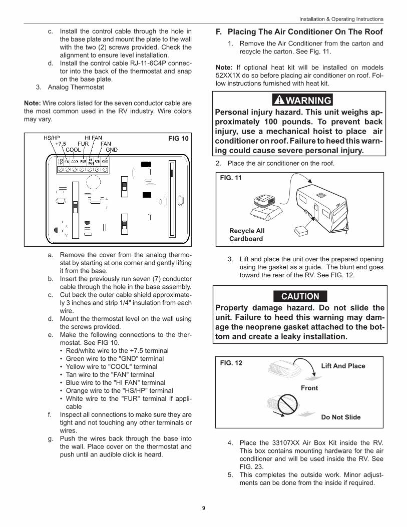
3. Analog Thermostat
Note: Wire colors listed for the seven conductor cable are the most common used in the RV industry. Wire colors may vary.
a. Remove the cover from the analog thermo-stat by starting at one corner and gently lifting it from the base.
b. Insert the previously run seven (7) conductor cable through the hole in the base assembly.
c. Cut back the outer cable shield approximate-ly 3 inches and strip 1/4" insulation from each wire.
d. Mount the thermostat level on the wall using the screws provided.
e. Make the following connections to the ther-mostat. See FIG 10.• Red/white wire to the +7.5 terminal• Green wire to the "GND" terminal• Yellow wire to "COOL" terminal• Tan wire to the "FAN" terminal• Blue wire to the "HI FAN" terminal• Orange wire to the "HS/HP" terminal• White wire to the "FUR" terminal if appli-
cablef. Inspect all connections to make sure they are
tight and not touching any other terminals or wires.
g. Push the wires back through the base into the wall. Place cover on the thermostat and push until an audible click is heard.
1. Remove the Air Conditioner from the carton and recycle the carton. See Fig. 11.
Note: If optional heat kit will be installed on models 52XX1X do so before placing air conditioner on roof. Fol-low instructions furnished with heat kit.
2. Place the air conditioner on the roof.
3. Lift and place the unit over the prepared opening using the gasket as a guide. The blunt end goes toward the rear of the RV. See FIG. 12.
4. Place the 33107XX Air Box Kit inside the RV.
This box contains mounting hardware for the air conditioner and will be used inside the RV. See FIG. 23.
5. This completes the outside work. Minor adjust-ments can be done from the inside if required.
Personal injury hazard. This unit weighs ap-proximately 100 pounds. To prevent back injury, use a mechanical hoist to place air conditioner on roof. Failure to heed this warn-ing could cause severe personal injury.
F. Placing The Air Conditioner On The Roof
FIG. 11
Recycle All Cardboard
Property damage hazard. Do not slide the unit. Failure to heed this warning may dam-age the neoprene gasket attached to the bot-tom and create a leaky installation.
Lift And Place
Do Not Slide
FIG. 12
Front
FIG 10
CAUTION
10
Installation & Operating Instructions
G. Discharge Duct And Ceiling Template In-stallation
1. Remove air box and mounting hardware from carton.
2. Remove wire tie holding center of rear aluminum bracket to plastic template.
3. Check for correct alignment of air conditioner and adjust as necessary (Roof Gasket centers over 14-1/4" x 14-1/4" (±1/8") opening).
4. Reach up into return air opening of the air condi-tioner and pull the unit electrical cord and thermo-stat wires, for electronic versions, down for later connection. See FIG. 13.
Note: If optional heat package is to be installed in model 520XXX series, do so prior to installing the template. Fol-low instructions furnished with heat kit. (Heat is not avail-able for hi-efficiency model 520300 used with the 3310741 Air Distribution Box or hi-efficiency model 521700 used with the 3310742 Air Distribution Box.) Electric Heat is factory pre-installed on 62041, 62051 & 62071 Penguin models.
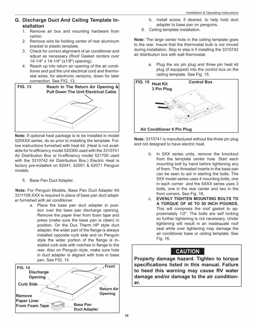
5. Base Pan Duct Adapter.
Note: For Penguin Models, Base Pan Duct Adapter Kit 3311109.XXX is required in place of base pan duct adapt-er furnished with air conditioner.
a. Place the base pan duct adapter in posi-tion over the base pan discharge opening. Remove the paper liner from foam tape and press (make sure the base pan is clean) in position. On the Duo Therm HP style duct adapter, the wider part of the flange is always installed opposite curb side and on Penguin style the wider portion of the flange is in-stalled curb side with notches in flange to the rear. Also on Penguin style, make sure hole in duct adapter is aligned with hole in base pan. See FIG. 14.
FIG. 13 Reach In The Return Air Opening & Pull Down The Unit Electrical Cable
b. Install screw, if desired, to help hold duct adapter to base pan on penguins.
6. Ceiling template installation.
Note: The large center hole in the ceiling template goes to the rear. Insure that the thermostat bulb is not moved during installation. Skip to step b if installing the 3310742 air distribution box with wall thermostat. a. Plug the six pin plug and three pin heat kit
plug (if equipped) into the control box on the ceiling template. See Fig. 15.
Note: 3310741 is manufactured without the three pin plug and not designed to have electric heat. b. In 6XX series units, remove the knockout
from the template center hole. Start each mounting bolt by hand before tightening any of them. The threaded inserts in the base pan can be seen to aid in starting the bolts. The 5XX model series uses 4 mounting bolts, one in each corner and the 6XXX series uses 3 bolts, one in the rear center and two in the front corners. See Fig. 16.
c. EVENLY TIGHTEN MOUNTING BOLTS TO A TORQUE OF 40 TO 50 INCH POUNDS. This will compress the roof gasket to ap-proximately 1/2". The bolts are self locking so further tightening is not necessary. Under tightening will result in an inadequate roof seal while over tightening may damage the air conditioner base or ceiling template. See Fig. 16.
Return AirOpening
Base PanDuct Adapter
FrontFIG. 14
Heat Kit3 Pin Plug
Air Conditioner 6 Pin Plug
FIG. 15
Property damage hazard. Tighten to torque specifications listed in this manual. Failure to heed this warning may cause RV water damage and/or damage to the air condition-er.
Discharge Opening
RemovePaper LinerFrom Foam Tape
Curb Side
Control Box
CAUTION
11
Installation & Operating Instructions
H. Wiring The System
Note: Wiring must comply with NFPA 70: National Elec-trical Code regulations and any State or Local Codes or regulations.
a. Secure Romex to side of roof opening with a staple or clamp approved for this purpose.
b. Route the previously run 120 VAC supply line into control box or junction box through provided strain relief. Cut wire leaving six (6) inch lead for connection to unit wires.
Note: Connect wiring per schematic with UL listed wire connectors for size of wire being connected.
c. Connect white wire in control box or junction box to white or neutral wire from supply line.
d. Connect black wire in control box or junction box to black or hot wire from supply line.
e. Connect supply ground wire to green wire in control box or junction box.
f. 3310700 or 3310741 models, insert back edge of cover under tabs and snap control box cover into place. Secure cover with screw (provided). See FIG. 18. For 3310742 mod-els, install the junction box cover with screws provided.
2. Connection Of Low Voltage Wiring (Comfort Con-trol Center, Digital, and Analog systems) (For 3310700 & 3310741 mechanical control models wiring is complete. Go to Section J)
FIG. 16
Start MountingBolts By Hand
Trim Duct 1/2" to 1 " Below Ceiling Template
CeilingTemplate
Do Not Disturb Thermostat Bulb
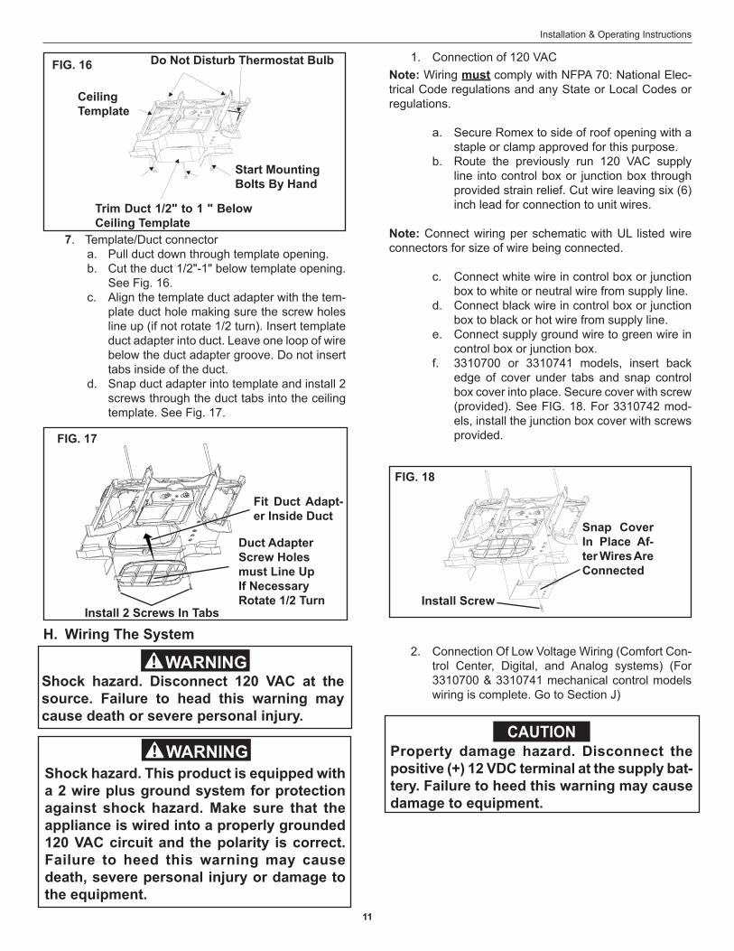
7. Template/Duct connector a. Pull duct down through template opening. b. Cut the duct 1/2"-1" below template opening.
See Fig. 16. c. Align the template duct adapter with the tem-
plate duct hole making sure the screw holes line up (if not rotate 1/2 turn). Insert template duct adapter into duct. Leave one loop of wire below the duct adapter groove. Do not insert tabs inside of the duct.
d. Snap duct adapter into template and install 2 screws through the duct tabs into the ceiling template. See Fig. 17.
FIG. 17
Install 2 Screws In Tabs
Duct AdapterScrew Holesmust Line UpIf NecessaryRotate 1/2 Turn
Fit Duct Adapt-er Inside Duct
Shock hazard. Disconnect 120 VAC at the source. Failure to head this warning may cause death or severe personal injury.
Shock hazard. This product is equipped with a 2 wire plus ground system for protection against shock hazard. Make sure that the appliance is wired into a properly grounded 120 VAC circuit and the polarity is correct. Failure to heed this warning may cause death, severe personal injury or damage to the equipment.
FIG. 18
Snap Cover In Place Af-ter Wires Are Connected
Property damage hazard. Disconnect the positive (+) 12 VDC terminal at the supply bat-tery. Failure to heed this warning may cause damage to equipment.
1. Connection of 120 VAC
Install Screw
CAUTION
12
Installation & Operating Instructions
Note: If optional solar panel is to be installed, do so at this time. Follow installation instructions packaged with solar panel.
a. Connect the previously run 12 VDC wires to the red and black wires protruding from the 14-1/4" x 14-1/4" (±1/8) roof opening. (In Comfort Control Center multiple zone instal-lations, this needs to be done at only one zone.) Connect +12 VDC to the red wire; –12 VDC to the black wire.
b. Connect the previously run furnace thermo-stat wires (if applicable) to the blue wires pro-truding from the 14-1/4" x 14-1/4"(±1/8") roof opening. The polarity of these connections does not matter.
c. Terminate the previously run 4 conductor con-trol cable(s) protruding into the 14-1/4" x 14-1/4" (±1/8") roof opening. The cable(s) must be terminated with a telephone RJ-11-6C4P connector. Refer to the crimp tool manufac-turer for crimping instructions. See FIG. 6 & 7.
Important: RJ-11-6C4P connectors must be installed with the same polarity on each end. Standard telephone cables will not operate the controls.
d Plug the control cable(s) into the telephone coupler(s) in the 14-1/4" x 14-1/4" (±1/8") roof opening. One for digital models and one for single zone comfort control center models. If more than one zone is used on the comfort control center models, the second coupler will be used to join each additional zone.
e. Remote Temperature Sensor (Comfort Con-trol Center models only). If applicable, con-nect the previously run Remote Temperature Sensor cable, to the connector that matches its color in the 14-1/4" x 14-1/4" (±1/8) roof opening.
f. Energy Management System (Comfort Con-trol Center Only). If applicable, connect the previously run Energy Management System wires to the yellow wires protruding from the 14-1/4" x 14-1/4" (±1/8") roof opening. The polarity of this connection does not matter.
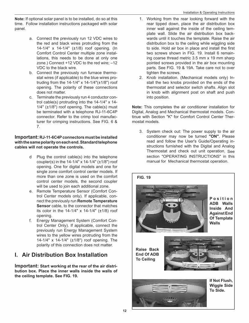
I. Air Distribution Box Installation
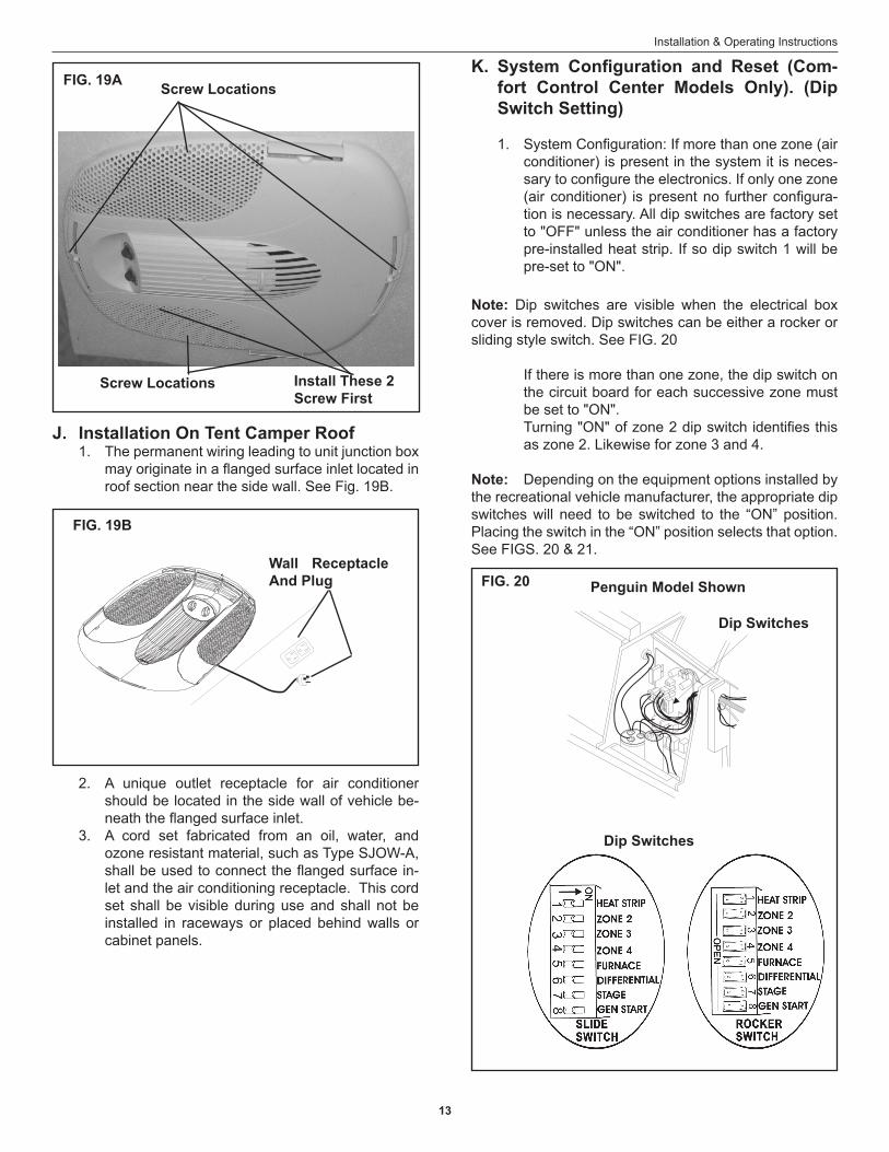
Important: Start working at the rear of the air distri-bution box. Place the inner walls inside the walls of the ceiling template. See FIG. 19.
1. Working from the rear looking forward with the rear tipped down, place the air distribution box inner wall against the inside of the ceiling tem-plate wall. Slide the air distribution box back-wards until it touches the template. Raise the air distribution box to the ceiling while wiggling side to side. Hold air box in place and install the first two screws shown in FIG. 19. Install 6 remain-ing coarse thread metric 3.5 mm x 19 mm sharp pointed screws provided in the air box mounting parts. See FIG. 19 & 19A. Take care not to over tighten the screws.
2. Knob installation. (Mechanical models only) In-stall the two knobs provided on the ends of the thermostat and selector switch shafts. Align slot in knob with alignment post on shaft and push into position.
Note: This completes the air conditioner installation for Digital, Analog and Mechanical thermostat models. Con-tinue with Section "K" for Comfort Control Center Ther-mostat models. 3. System check out: The power supply to the air
conditioner may now be turned "ON". Please read and follow the User's Guide/Operating in-structions furnished with the Digital and Analog Thermostat and check out unit operation. See section "OPERATING INSTRUCTIONS" in this manual for Mechanical thermostat operation.
FIG. 19
P o s i t i o n ADB Walls Inside And Against End Of Template Walls
Raise Back End Of ADB To Ceiling
If Not Flush, Wiggle Side To Side.
13
Installation & Operating Instructions
K. System Configuration and Reset (Com-fort Control Center Models Only). (Dip Switch Setting)
1. System Configuration: If more than one zone (air conditioner) is present in the system it is neces-sary to configure the electronics. If only one zone (air conditioner) is present no further configura-tion is necessary. All dip switches are factory set to "OFF" unless the air conditioner has a factory pre-installed heat strip. If so dip switch 1 will be pre-set to "ON".
Note: Dip switches are visible when the electrical box cover is removed. Dip switches can be either a rocker or sliding style switch. See FIG. 20
If there is more than one zone, the dip switch on the circuit board for each successive zone must be set to "ON".
Turning "ON" of zone 2 dip switch identifies this as zone 2. Likewise for zone 3 and 4.
Note: Depending on the equipment options installed by the recreational vehicle manufacturer, the appropriate dip switches will need to be switched to the “ON” position. Placing the switch in the “ON” position selects that option. See FIGS. 20 & 21.
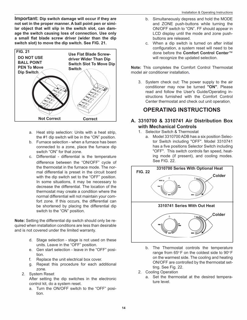
J. Installation On Tent Camper Roof 1. The permanent wiring leading to unit junction box
may originate in a flanged surface inlet located in roof section near the side wall. See Fig. 19B.
2. A unique outlet receptacle for air conditioner should be located in the side wall of vehicle be-neath the flanged surface inlet.
3. A cord set fabricated from an oil, water, and ozone resistant material, such as Type SJOW-A, shall be used to connect the flanged surface in-let and the air conditioning receptacle. This cord set shall be visible during use and shall not be installed in raceways or placed behind walls or cabinet panels.
Screw Locations
Screw Locations
FIG. 19A
Install These 2 Screw First
FIG. 20
Dip Switches
Penguin Model Shown
Dip Switches
FIG. 19B
Wall Receptacle And Plug
14
Installation & Operating Instructions
difference between the “ON/OFF” cycle of the thermostat in the furnace mode. The nor-mal differential is preset in the circuit board with the dip switch set to the “OFF” position. In some situations, it may be necessary to decrease the differential. The location of the thermostat may create a condition where the normal differential will not maintain your com-fort zone. If this occurs, the differential can be shortened by placing the differential dip switch to the “ON” position.
Note: Setting the differential dip switch should only be re-quired when installation conditions are less than desirable and is not covered under the limited warranty.
d. Stage selection - stage is not used on these units. Leave in the “OFF” position.
e. Gen start selection - leave in the “OFF” posi-tion.
f. Replace the unit electrical box cover. g. Repeat this procedure for each additional
zone. 2. System Reset After setting the dip switches in the electronic
control kit, do a system reset.a. Turn the ON/OFF switch to the “OFF” posi-
tion.
OPERATING INSTRUCTIONS
A. 3310700 & 3310741 Air Distribution Box with Mechanical Controls
1. Selector Switch & Thermostat a. Model 3310700 ADB has a six position Selec-
tor Switch including "OFF". Model 3310741 has a five positions Selector Switch including "OFF". This switch controls fan speed, heat-ing mode (if present), and cooling modes. See FIG. 22.
3310700 Series With Optional Heat
3310741 Series With Out Heat
FIG. 22Colder
Colder
b. The Thermostat controls the temperature range from 65o F on the coldest side to 90o F on the warmest side. The cooling and heating ON/OFF are controlled by the thermostat set-ting. See Fig. 22.
2. Cooling Operationa. Set the thermostat at the desired tempera-
ture level.
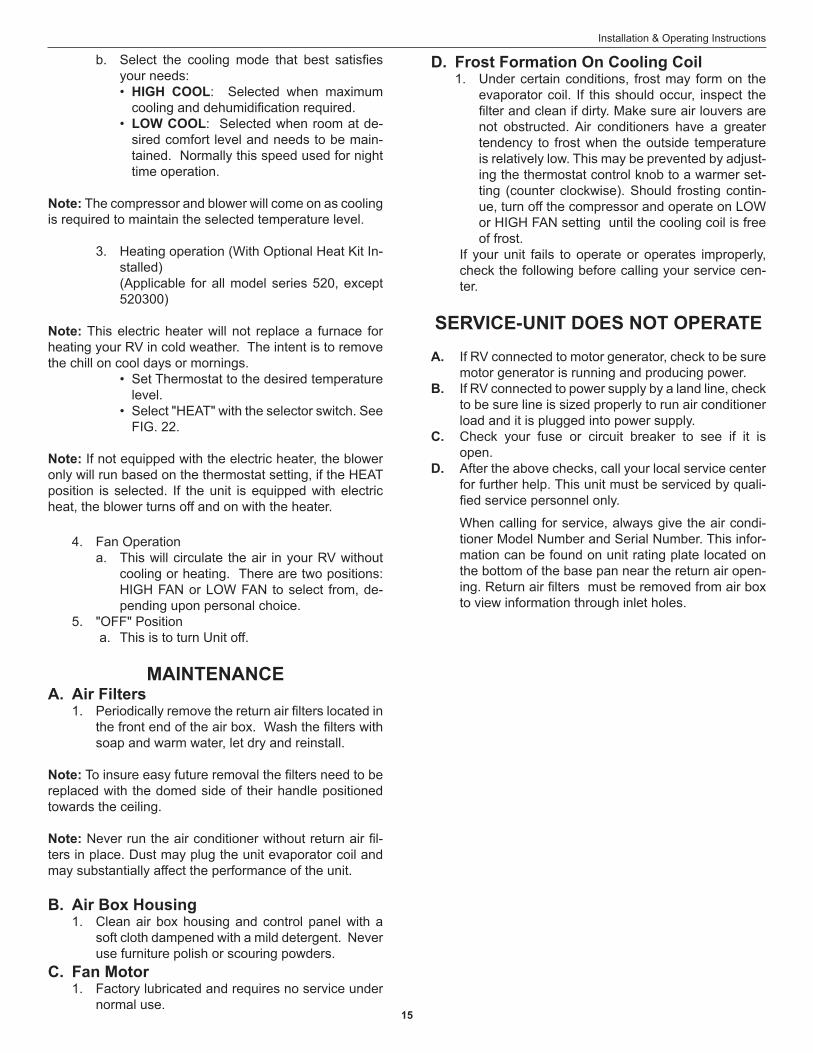
Important: Dip switch damage will occur if they are not set in the proper manner. A ball point pen or simi-lar object that will slip in the switch slot, can dam-age the switch causing loss of connection. Use only a small flat blade screw driver (wider than the dip switch slot) to move the dip switch. See FIG. 21.
FIG. 21
Not Correct
Use Flat Blade Screw-driver Wider Than Dip Switch Slot To Move Dip Switch
DO NOT USE BALL POINT PEN To Move Dip Switch
Correct
a. Heat strip selection: Units with a heat strip, the #1 dip switch will be in the “ON” position.
b. Furnace selection - when a furnace has been connected to a zone, place the furnace dip switch “ON” for that zone.
c. Differential - differential is the temperature
b. Simultaneously depress and hold the MODE and ZONE push-buttons while turning the ON/OFF switch to “ON”. FF should appear in LCD display until the mode and zone push-buttons are released.
c. When a dip switch is turned on after initial configuration, a system reset will need to be done before the Comfort Control Center™ will recognize the updated selection.
Note: This completes the Comfort Control Thermostat model air conditioner installation.
3. System check out: The power supply to the air conditioner may now be turned "ON". Please read and follow the User's Guide/Operating in-structions furnished with the Comfort Control Center thermostat and check out unit operation.
15
Installation & Operating Instructions
SERVICE-UNIT DOES NOT OPERATEA. If RV connected to motor generator, check to be sure
motor generator is running and producing power.B. If RV connected to power supply by a land line, check
to be sure line is sized properly to run air conditioner load and it is plugged into power supply.
C. Check your fuse or circuit breaker to see if it is open.
D. After the above checks, call your local service center for further help. This unit must be serviced by quali-fied service personnel only.
When calling for service, always give the air condi-tioner Model Number and Serial Number. This infor-mation can be found on unit rating plate located on the bottom of the base pan near the return air open-ing. Return air filters must be removed from air box to view information through inlet holes.
b. Select the cooling mode that best satisfies your needs:• HIGH COOL: Selected when maximum
cooling and dehumidification required.• LOW COOL: Selected when room at de-
sired comfort level and needs to be main-tained. Normally this speed used for night time operation.
Note: The compressor and blower will come on as cooling is required to maintain the selected temperature level.
3. Heating operation (With Optional Heat Kit In-stalled)
(Applicable for all model series 520, except 520300)
Note: This electric heater will not replace a furnace for heating your RV in cold weather. The intent is to remove the chill on cool days or mornings.
• Set Thermostat to the desired temperature level.
• Select "HEAT" with the selector switch. See FIG. 22.
Note: If not equipped with the electric heater, the blower only will run based on the thermostat setting, if the HEAT position is selected. If the unit is equipped with electric heat, the blower turns off and on with the heater.
4. Fan Operationa. This will circulate the air in your RV without
cooling or heating. There are two positions: HIGH FAN or LOW FAN to select from, de-pending upon personal choice.
5. "OFF" Position a. This is to turn Unit off.
MAINTENANCEA. Air Filters 1. Periodically remove the return air filters located in
the front end of the air box. Wash the filters with soap and warm water, let dry and reinstall.
Note: To insure easy future removal the filters need to be replaced with the domed side of their handle positioned towards the ceiling.
Note: Never run the air conditioner without return air fil-ters in place. Dust may plug the unit evaporator coil and may substantially affect the performance of the unit.
B. Air Box Housing 1. Clean air box housing and control panel with a
soft cloth dampened with a mild detergent. Never use furniture polish or scouring powders.
C. Fan Motor 1. Factory lubricated and requires no service under
normal use.
D. Frost Formation On Cooling Coil 1. Under certain conditions, frost may form on the
evaporator coil. If this should occur, inspect the filter and clean if dirty. Make sure air louvers are not obstructed. Air conditioners have a greater tendency to frost when the outside temperature is relatively low. This may be prevented by adjust-ing the thermostat control knob to a warmer set-ting (counter clockwise). Should frosting contin-ue, turn off the compressor and operate on LOW or HIGH FAN setting until the cooling coil is free of frost.
If your unit fails to operate or operates improperly, check the following before calling your service cen-ter.
16
Installation & Operating Instructions
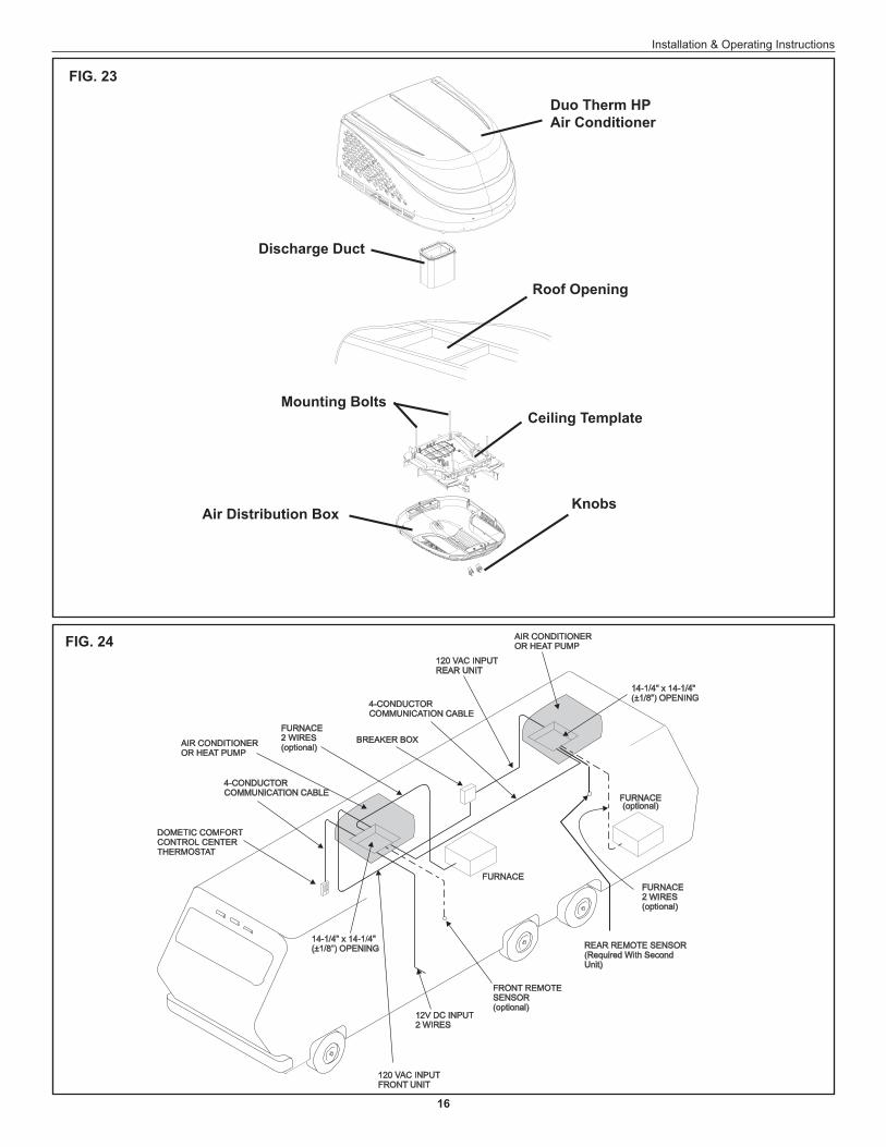
FIG. 23
FIG. 24
Duo Therm HPAir Conditioner
Roof Opening
Discharge Duct
Mounting BoltsCeiling Template
KnobsAir Distribution Box
17
Installation & Operating Instructions
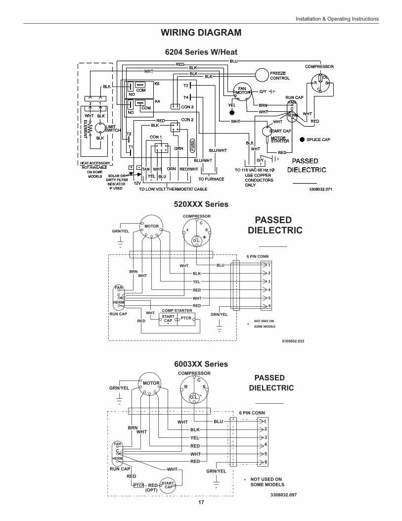
6003XX Series
520XXX Series
6204 Series W/Heat
WIRING DIAGRAM
18
Installation & Operating Instructions
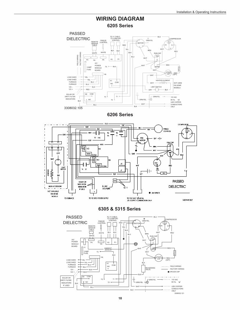
6205 Series
6206 Series
6305 & 5315 Series
WIRING DIAGRAM
19
Installation & Operating Instructions
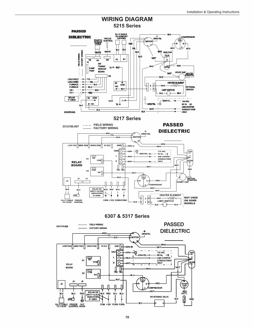
6307 & 5317 Series
5215 Series
5217 Series
WIRING DIAGRAM
20
Installation & Operating Instructions
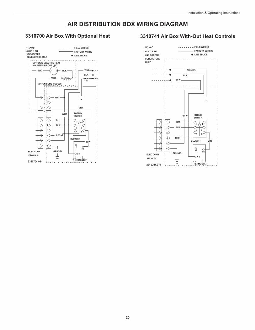
3310741 Air Box With-Out Heat Controls3310700 Air Box With Optional Heat
AIR DISTRIBUTION BOX WIRING DIAGRAM