Embed Size (px)
Citation preview
Journal of Robotics and Mechanical Engineering Research
Air Craft Winglet Design and Performance: Cant Angle Effect
Eslam Said Abdelghany 1, Essam E Khalil2*, Osama E Abdellatif 3 and Gamal elhariry 4
1Lecturer, Institute of Aviation Engineering, Cairo, Egypt 2Professor of Mechanical Engineering, Cairo University, Egypt
3Professor of Mechanical Engineering, Benha University, Egypt 4Lecturer of Mechanical Engineering. Cairo University, Egypt
www.verizonaonlinepublishing.com
J Robot Mech Eng Resr 1(3). Page | 28
*Corresponding author: Essam E. Khalil, Professor of Mechanical Engineering, Cairo University, Egypt; E mail: [email protected]
Article Type: Research, Submission Date: 01 February 2016, Accepted Date: 25 February 2016, Published Date: 08 March 2016.
Citation: Eslam Said Abdelghany, Essam E Khalil, Osama E Abdellatif and Gamal elhariry (2016) Air Craft Winglet Design and Performance: Cant Angle Effect. J Robot Mech Eng Resr 1(3): 28-34.
Copyright: © 2016 Essam E. Khalil, et al. This is an open-access article distributed under the terms of the Creative Commons Attribution License, which permits unrestricted use, distribution, and reproduction in any medium, provided the original author and source are credited.
Vol: 1, Issue: 3
Abstract
A winglet is a device used to improve the efficiency of aircraft by lowering the lift induced drag caused by wingtip vortices. It is a vertical or angled extension at the tips of each wing. Winglets improve efficiency by diffusing the shed wingtip vortex, which in turn reduces the drag due to lift and improves the wing’s lift over drag ratio Winglets increase the effective aspect ratio of a wing without adding greatly to the structural stress and hence necessary weight of its structure. In this research, a numerical validation procedure (by FLUENT ®, computational fluid dynamics software with The Spalart-Allmaras turbulence model) is described for determination and estimation aerodynamic characteristics of three dimension subsonic rectangular wing (with NACA653218airfoil cross section). It was observed that at the present work a good agreement between the numerical study and the experimental work. This paper describes a CFD 3-dimensional winglets analysis that was performed on a Cessna wing of NACA2412 cross sectional airfoil. The wing has span 13.16 m, root chord 1.857 m, tip chord 0.928 m, sweep angle 11 degree and taper ratio 0.5. The present study shows wing without winglet and wing with winglet at cant angle 0, 30 and 45 degree. A CFD simulation performs by to compare of aerodynamics characteristics of lift coefficient CL, drag coefficient CD and lift to drag ratio, L/D lift, pathlines and pressure contours. The models run at a Mach number of 0.2 at sea level. The pressure and temperature of air at this height are 101.325 kPa and 288.2 K respectively. The results show that the wing with winglet can increase the lift by ratio approximately 12%. The wing with winglet can decrease the drag by ratio approximately 4%. The wing with winglet can increase lift to drag, L/D by about 11% along different phases of flight.
Keywords: CFD, Winglet, Induce drag, Lift, Vortices, Cant angle.
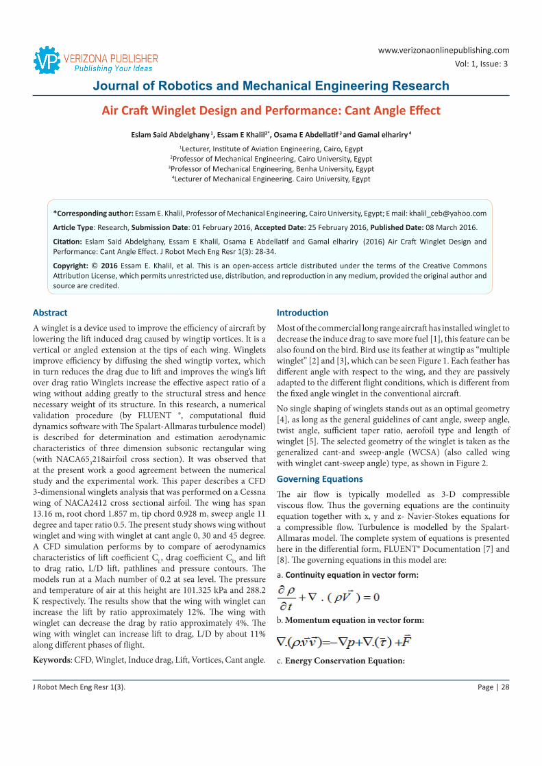
IntroductionMost of the commercial long range aircraft has installed winglet to decrease the induce drag to save more fuel [1], this feature can be also found on the bird. Bird use its feather at wingtip as “multiple winglet” [2] and [3], which can be seen Figure 1. Each feather has different angle with respect to the wing, and they are passively adapted to the different flight conditions, which is different from the fixed angle winglet in the conventional aircraft.
No single shaping of winglets stands out as an optimal geometry [4], as long as the general guidelines of cant angle, sweep angle, twist angle, sufficient taper ratio, aerofoil type and length of winglet [5]. The selected geometry of the winglet is taken as the generalized cant-and sweep-angle (WCSA) (also called wing with winglet cant-sweep angle) type, as shown in Figure 2.
Governing EquationsThe air flow is typically modelled as 3-D compressible viscous flow. Thus the governing equations are the continuity equation together with x, y and z- Navier-Stokes equations for a compressible flow. Turbulence is modelled by the Spalart-Allmaras model. The complete system of equations is presented here in the differential form, FLUENT® Documentation [7] and [8]. The governing equations in this model are:
a. Continuity equation in vector form:
b. Momentum equation in vector form:
c. Energy Conservation Equation:
J Robot Mech Eng Resr 1(3). Page | 29
Citation: Eslam Said Abdelghany, Essam E Khalil, Osama E Abdellatif and Gamal elhariry (2016) Air Craft Winglet Design and Performance: Cant Angle Effect. J Robot Mech Eng Resr 1(3): 28-34.
Validation Code ProceduresThe computational steps in this work consist of three stages. The work began from pre-processing stage of geometry setup and grid generation. The geometry of the model and the grid was generated by GAMBIT. The second stage was the computational simulation by FLUENT solver using Finite Volume Approach. Finally is the post-processing stage where the aerodynamics characteristics of rectangular wing with NACA653218 airfoil were performed. From CFD model one can determine lift, drag, pitching moment coefficient, pressure contours, velocity contours and pathlines around wing at all AOA.
Geometry and Grids
First draw rectangular wing with NACA 653218airfoil by using Gambit. The wing has chord length 121 mm and semi-span 330mm. In order to obtain accurate lift, drag, and pitching moment on wing, the utilized grid nodes near the wing volume must be dense enough and the computed fields must be large enough to satisfy the far field boundary conditions. 3D unstructured tetrahedral mesh is used for complex shape of winglet. In the present work multi-block unstructured grid was used to increase grids near wing volume by creating blocks 1, 2, 3, 4, 5 and 6, as shown in Figure 3.
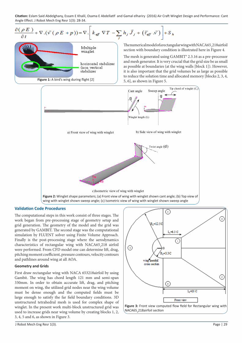
The numerical model of a rectangular wing with NACA653218airfoil section with boundary condition is illustrated here in Figure 4.
The mesh is generated using GAMBIT® 2.3.16 as a pre-processor and mesh generator. It is very crucial that the grid size be as small as possible at boundaries (at the wing walls [block 1]). However, it is also important that the grid volumes be as large as possible to reduce the solution time and allocated memory [blocks 2, 3, 4, 5, 6], as shown in Figure 5.Figure 1: A bird’s wing during flight [2]
Cant angle
a) Front view of wing with winglet
q
Sweep angle
b) Side view of wing with winglet
c)Isometric view of wing with winglet
g
Tip chord of winglet (Ct)
Winglet length (L)
Twist angle ( )d
Figure 2: Winglet shape parameters; (a) Front view of wing with winglet shown cant angle; (b) Top view of wing with winglet shown sweep angle; (c) Isometric view of wing with winglet shown sweep angle
Figure 3: Front view computed flow field for Rectangular wing with NACA653218airfoil section
J Robot Mech Eng Resr 1(3). Page | 30
Citation: Eslam Said Abdelghany, Essam E Khalil, Osama E Abdellatif and Gamal elhariry (2016) Air Craft Winglet Design and Performance: Cant Angle Effect. J Robot Mech Eng Resr 1(3): 28-34.
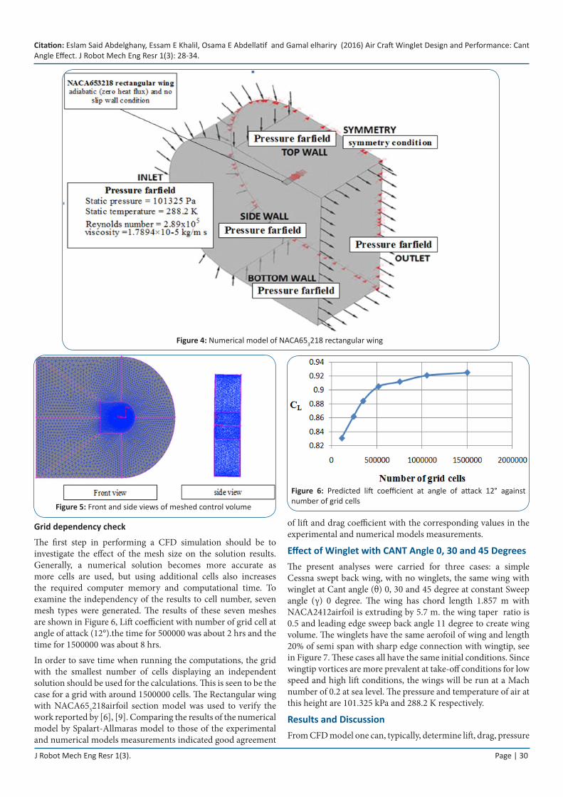
Grid dependency check
The first step in performing a CFD simulation should be to investigate the effect of the mesh size on the solution results. Generally, a numerical solution becomes more accurate as more cells are used, but using additional cells also increases the required computer memory and computational time. To examine the independency of the results to cell number, seven mesh types were generated. The results of these seven meshes are shown in Figure 6, Lift coefficient with number of grid cell at angle of attack (12°).the time for 500000 was about 2 hrs and the time for 1500000 was about 8 hrs.
In order to save time when running the computations, the grid with the smallest number of cells displaying an independent solution should be used for the calculations. This is seen to be the case for a grid with around 1500000 cells. The Rectangular wing with NACA653218airfoil section model was used to verify the work reported by [6], [9]. Comparing the results of the numerical model by Spalart-Allmaras model to those of the experimental and numerical models measurements indicated good agreement
of lift and drag coefficient with the corresponding values in the experimental and numerical models measurements.
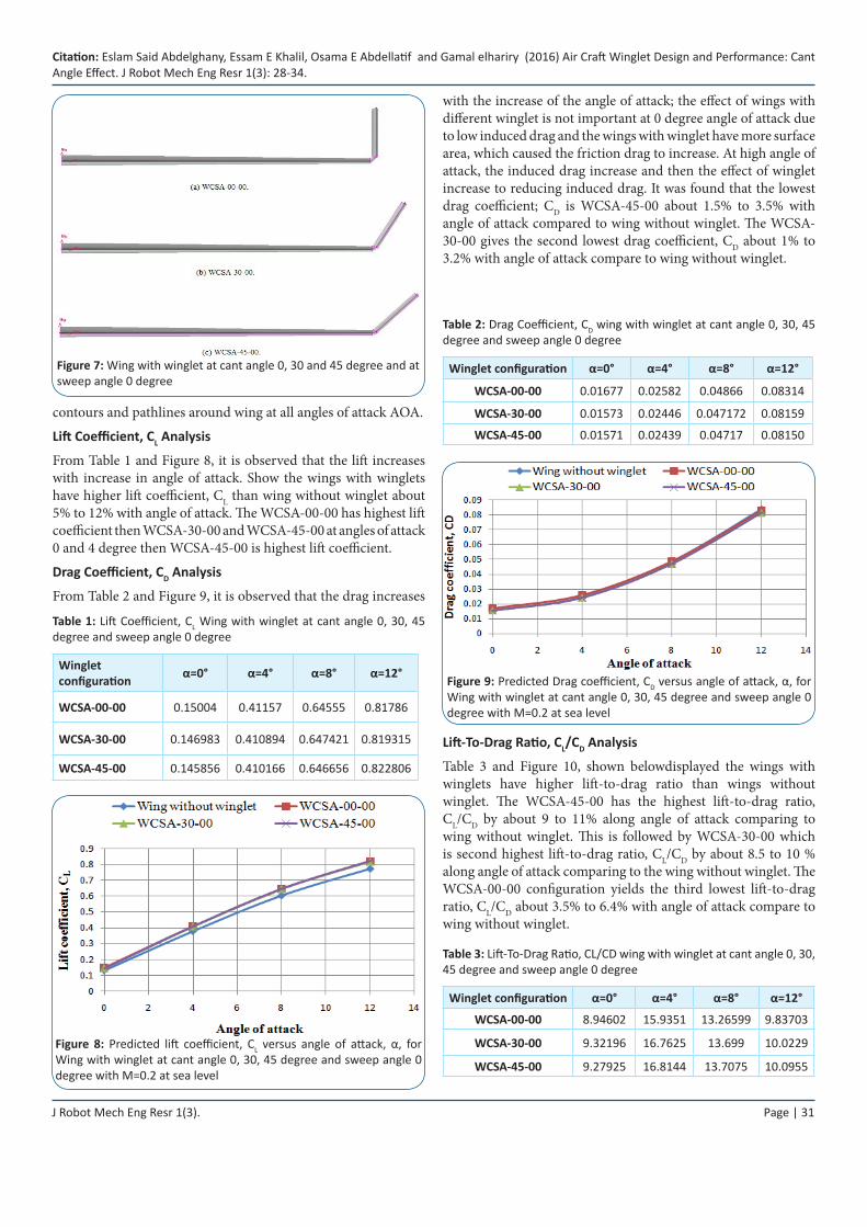
Effect of Winglet with CANT Angle 0, 30 and 45 DegreesThe present analyses were carried for three cases: a simple Cessna swept back wing, with no winglets, the same wing with winglet at Cant angle (θ) 0, 30 and 45 degree at constant Sweep angle (γ) 0 degree. The wing has chord length 1.857 m with NACA2412airfoil is extruding by 5.7 m. the wing taper ratio is 0.5 and leading edge sweep back angle 11 degree to create wing volume. The winglets have the same aerofoil of wing and length 20% of semi span with sharp edge connection with wingtip, see in Figure 7. These cases all have the same initial conditions. Since wingtip vortices are more prevalent at take-off conditions for low speed and high lift conditions, the wings will be run at a Mach number of 0.2 at sea level. The pressure and temperature of air at this height are 101.325 kPa and 288.2 K respectively.
Results and DiscussionFrom CFD model one can, typically, determine lift, drag, pressure
Figure 4: Numerical model of NACA653218 rectangular wing
Figure 5: Front and side views of meshed control volume
Figure 6: Predicted lift coefficient at angle of attack 12° against number of grid cells
Citation: Eslam Said Abdelghany, Essam E Khalil, Osama E Abdellatif and Gamal elhariry (2016) Air Craft Winglet Design and Performance: Cant Angle Effect. J Robot Mech Eng Resr 1(3): 28-34.
J Robot Mech Eng Resr 1(3). Page | 31
contours and pathlines around wing at all angles of attack AOA.
Lift Coefficient, CL Analysis
From Table 1 and Figure 8, it is observed that the lift increases with increase in angle of attack. Show the wings with winglets have higher lift coefficient, CL than wing without winglet about 5% to 12% with angle of attack. The WCSA-00-00 has highest lift coefficient then WCSA-30-00 and WCSA-45-00 at angles of attack 0 and 4 degree then WCSA-45-00 is highest lift coefficient.
Drag Coefficient, CD Analysis
From Table 2 and Figure 9, it is observed that the drag increases
Figure 7: Wing with winglet at cant angle 0, 30 and 45 degree and at sweep angle 0 degree
Table 1: Lift Coefficient, CL Wing with winglet at cant angle 0, 30, 45 degree and sweep angle 0 degree
Winglet configuration α=0° α=4° α=8° α=12°
WCSA-00-00 0.15004 0.41157 0.64555 0.81786
WCSA-30-00 0.146983 0.410894 0.647421 0.819315
WCSA-45-00 0.145856 0.410166 0.646656 0.822806
Figure 8: Predicted lift coefficient, CL versus angle of attack, α, for Wing with winglet at cant angle 0, 30, 45 degree and sweep angle 0 degree with M=0.2 at sea level
with the increase of the angle of attack; the effect of wings with different winglet is not important at 0 degree angle of attack due to low induced drag and the wings with winglet have more surface area, which caused the friction drag to increase. At high angle of attack, the induced drag increase and then the effect of winglet increase to reducing induced drag. It was found that the lowest drag coefficient; CD is WCSA-45-00 about 1.5% to 3.5% with angle of attack compared to wing without winglet. The WCSA-30-00 gives the second lowest drag coefficient, CD about 1% to 3.2% with angle of attack compare to wing without winglet.
Table 2: Drag Coefficient, CD wing with winglet at cant angle 0, 30, 45 degree and sweep angle 0 degree
Winglet configuration α=0° α=4° α=8° α=12°
WCSA-00-00 0.01677 0.02582 0.04866 0.08314
WCSA-30-00 0.01573 0.02446 0.047172 0.08159
WCSA-45-00 0.01571 0.02439 0.04717 0.08150
Figure 9: Predicted Drag coefficient, CD versus angle of attack, α, for Wing with winglet at cant angle 0, 30, 45 degree and sweep angle 0 degree with M=0.2 at sea level
Lift-To-Drag Ratio, CL/CD Analysis
Table 3 and Figure 10, shown belowdisplayed the wings with winglets have higher lift-to-drag ratio than wings without winglet. The WCSA-45-00 has the highest lift-to-drag ratio, CL/CD by about 9 to 11% along angle of attack comparing to wing without winglet. This is followed by WCSA-30-00 which is second highest lift-to-drag ratio, CL/CD by about 8.5 to 10 % along angle of attack comparing to the wing without winglet. The WCSA-00-00 configuration yields the third lowest lift-to-drag ratio, CL/CD about 3.5% to 6.4% with angle of attack compare to wing without winglet.
Table 3: Lift-To-Drag Ratio, CL/CD wing with winglet at cant angle 0, 30, 45 degree and sweep angle 0 degree
Winglet configuration α=0° α=4° α=8° α=12°
WCSA-00-00 8.94602 15.9351 13.26599 9.83703
WCSA-30-00 9.32196 16.7625 13.699 10.0229
WCSA-45-00 9.27925 16.8144 13.7075 10.0955
J Robot Mech Eng Resr 1(3). Page | 32
Citation: Eslam Said Abdelghany, Essam E Khalil, Osama E Abdellatif and Gamal elhariry (2016) Air Craft Winglet Design and Performance: Cant Angle Effect. J Robot Mech Eng Resr 1(3): 28-34.
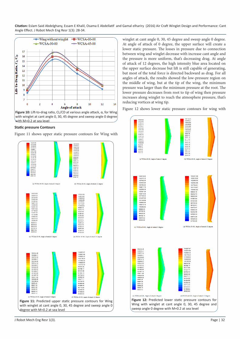
Static pressure Contours
Figure 11 shows upper static pressure contours for Wing with
Figure 11: Predicted upper static pressure contours for Wing with winglet at cant angle 0, 30, 45 degree and sweep angle 0 degree with M=0.2 at sea level
Figure 10: Lift-to-drag ratio, CL/CD at various angle attack, α, for Wing with winglet at cant angle 0, 30, 45 degree and sweep angle 0 degree with M=0.2 at sea level
winglet at cant angle 0, 30, 45 degree and sweep angle 0 degree. At angle of attack of 0 degree, the upper surface will create a lower static pressure. The losses in pressure due to connection between wing and winglet decrease with increase cant angle and the pressure is more uniform, that’s decreasing drag. At angle of attack of 12 degrees, the high intensity blue area located on the upper surface decrease but lift is still capable of generating, but most of the total force is directed backward as drag. For all angles of attack, the results showed the low-pressure region on the middle of wing, but at the tip of the wing, the minimum pressure was larger than the minimum pressure at the root. The lower pressure decreases from root to tip of wing then pressure increases along winglet to reach the atmosphere pressure, that’s reducing vortices at wing tip.
Figure 12 shows lower static pressure contours for wing with
Figure 12: Predicted lower static pressure contours for Wing with winglet at cant angle 0, 30, 45 degree and sweep angle 0 degree with M=0.2 at sea level
Citation: Eslam Said Abdelghany, Essam E Khalil, Osama E Abdellatif and Gamal elhariry (2016) Air Craft Winglet Design and Performance: Cant Angle Effect. J Robot Mech Eng Resr 1(3): 28-34.
J Robot Mech Eng Resr 1(3). Page | 33
winglet at cant angle 0, 30, 45 degree and sweep angle 0 degree. When the angle of attack increases, the lower surface will create a higher static pressure. The high intensity red area located on the lower surface suggests high lift is generated at high angle of attack, α. For all angle of attack, it shows the high-pressure region on the middle of wing, but at the tip of the wing, the high pressure is lower than the high pressure at the root. The higher pressure decreased from root to tip and along winglet to reach the atmosphere pressure.
Pathlines
The difference in pressure between both upper and lower surface of wing made the vortex. When angle of attack was increased, the difference in pressure increased then the vortex and the drag of wing was increased. The wing alone presents only one large vortex at the wingtip as expected. The rotation sense is easily deductible from pathlines. From this, one can realize that effectively fluid has a wide tendency to go from lower to upper surfaces.
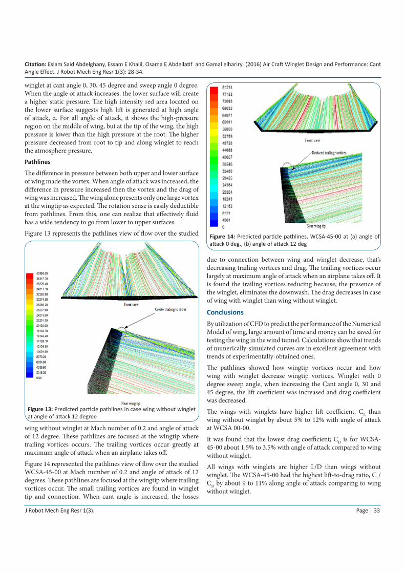
Figure 13 represents the pathlines view of flow over the studied
Figure 13: Predicted particle pathlines in case wing without winglet at angle of attack 12 degree
wing without winglet at Mach number of 0.2 and angle of attack of 12 degree. These pathlines are focused at the wingtip where trailing vortices occurs. The trailing vortices occur greatly at maximum angle of attack when an airplane takes off.
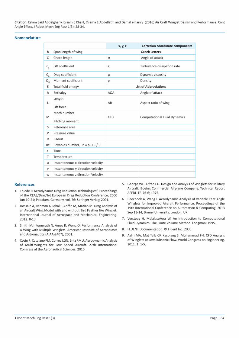
Figure 14 represented the pathlines view of flow over the studied WCSA-45-00 at Mach number of 0.2 and angle of attack of 12 degrees. These pathlines are focused at the wingtip where trailing vortices occur. The small trailing vortices are found in winglet tip and connection. When cant angle is increased, the losses
Figure 14: Predicted particle pathlines, WCSA-45-00 at (a) angle of attack 0 deg., (b) angle of attack 12 deg
due to connection between wing and winglet decrease, that’s decreasing trailing vortices and drag. The trailing vortices occur largely at maximum angle of attack when an airplane takes off. It is found the trailing vortices reducing because, the presence of the winglet, eliminates the downwash. The drag decreases in case of wing with winglet than wing without winglet.
ConclusionsBy utilization of CFD to predict the performance of the Numerical Model of wing, large amount of time and money can be saved for testing the wing in the wind tunnel. Calculations show that trends of numerically-simulated curves are in excellent agreement with trends of experimentally-obtained ones.
The pathlines showed how wingtip vortices occur and how wing with winglet decrease wingtip vortices. Winglet with 0 degree sweep angle, when increasing the Cant angle 0, 30 and 45 degree, the lift coefficient was increased and drag coefficient was decreased.
The wings with winglets have higher lift coefficient, CL than wing without winglet by about 5% to 12% with angle of attack at WCSA 00-00.
It was found that the lowest drag coefficient; CD is for WCSA-45-00 about 1.5% to 3.5% with angle of attack compared to wing without winglet.
All wings with winglets are higher L/D than wings without winglet. The WCSA-45-00 had the highest lift-to-drag ratio, CL/CD by about 9 to 11% along angle of attack comparing to wing without winglet.
Citation: Eslam Said Abdelghany, Essam E Khalil, Osama E Abdellatif and Gamal elhariry (2016) Air Craft Winglet Design and Performance: Cant Angle Effect. J Robot Mech Eng Resr 1(3): 28-34.
J Robot Mech Eng Resr 1(3). Page | 34
Nomenclature
x, y, z Cartesian coordinate components
b Span length of wing Greek Letters
C Chord length α Angle of attack
CL Lift coefficient ε Turbulence dissipation rate
CD Drag coefficient μ Dynamic viscosity
CM Moment coefficient ρ Density
E Total fluid energy List of Abbreviations
h Enthalpy AOA Angle of attack
LLength
Lift forceAR Aspect ratio of wing
MMach number
Pitching momentCFD Computational Fluid Dynamics
S Reference area
P Pressure value
R Radius
Re Reynolds number, Re = ρ U C / μ
t Time
T Temperature
u Instantaneous x direction velocity
v Instantaneous y direction velocity
w Instantaneous z direction Velocity
References 1. Thiede P. Aerodynamic Drag Reduction Technologies”, Proceedings
of the CEAS/DragNet European Drag Reduction Conference; 2000 Jun 19-21; Potsdam, Germany. vol. 76: Springer Verlag; 2001.
2. Hossain A, Rahman A, Iqbal P, Ariffin M, Mazian M. Drag Analysis of an Aircraft Wing Model with and without Bird Feather like Winglet. International Journal of Aerospace and Mechanical Engineering. 2012: 8-13.
3. Smith MJ, Komerath N, Ames R, Wong O. Performance Analysis of A Wing with Multiple Winglets. American Institute of Aeronautics and Astronautics (AIAA-2407); 2001.
4. Cosin R, Catalano FM, Correa LGN, Entz RMU. Aerodynamic Analysis of Multi-Winglets for Low Speed Aircraft. 27th International Congress of the Aeronautical Sciences; 2010.
5. George WL, Alfred CD. Design and Analysis of Winglets for Military Aircraft. Boeing Commercial Airplane Company, Technical Report AFFDL-TR-76-6; 1975.
6. Beechook A, Wang J. Aerodynamic Analysis of Variable Cant Angle Winglets for Improved Aircraft Performance. Proceedings of the 19th International Conference on Automation & Computing; 2013 Sep 13-14; Brunel University, London, UK.
7. Versteeg H, Malalasekera W. An Introduction to Computational Fluid Dynamics: The Finite Volume Method. Longman; 1995.
8. FLUENT Documentation. © Fluent Inc. 2005.
9. Azlin MA, Mat Taib CF, Kasolang S, Muhammad FH. CFD Analysis of Winglets at Low Subsonic Flow. World Congress on Engineering. 2011; 1: 1-5.