Embed Size (px)
Citation preview
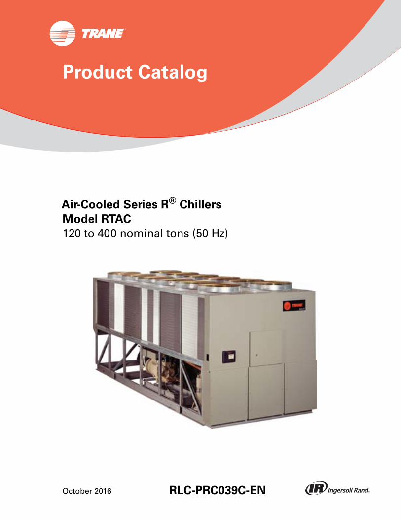
Air-Cooled Series R® Chillers
Model RTAC
120 to 400 nominal tons (50 Hz)
October 2016 RLC-PRC039C-EN
Product Catalog
© 2016 Ingersoll Rand All rights reserved RLC-PRC039C-EN
Introduction
Like its chillers,Trane wants its relationships with customers to last.Trane is interested inmaintaining long term, loyal relationships.This perspective means the point in time that acustomer purchases a chiller is the beginning of a relationship, not the end.Your business isimportant, but your satisfaction is paramount.
The RTAC offers high reliability coupled with proven Series R® performance.
The Series R® Model RTAC is an industrial grade design built for both the industrial and commercialmarkets. It is ideal for schools, hospitals, retailers, office buildings, internet service providers andmanufacturing facilities.
Copyright
This document and the information in it are the property ofTrane, and may not be used orreproduced in whole or in part without written permission.Trane reserves the right to revise thispublication at any time, and to make changes to its content without obligation to notify any personof such revision or change.
Trademarks
All trademarks referenced in this document are the trademarks of their respective owners.
Revision History
• Updated general data water storage and minimum/maximum flow rate information foroptimization project.
• Updated fan FLA electrical data to reflect current fan configurations.
RLC-PRC039C-EN 3
Table of Contents
Introduction . . . . . . . . . . . . . . . . . . . . . . . . . . . . . . . . . . . . . . . . . . . . . . . . . . . . . . 2
Features and Benefits . . . . . . . . . . . . . . . . . . . . . . . . . . . . . . . . . . . . . . . . . . . . . . 4
Application Considerations . . . . . . . . . . . . . . . . . . . . . . . . . . . . . . . . . . . . . . . . . . 7
Model Number Descriptions . . . . . . . . . . . . . . . . . . . . . . . . . . . . . . . . . . . . . . . . 13
General Data . . . . . . . . . . . . . . . . . . . . . . . . . . . . . . . . . . . . . . . . . . . . . . . . . . . 14
Controls . . . . . . . . . . . . . . . . . . . . . . . . . . . . . . . . . . . . . . . . . . . . . . . . . . . . . . . . 18
Electrical Data . . . . . . . . . . . . . . . . . . . . . . . . . . . . . . . . . . . . . . . . . . . . . . . . . . . . 21
Electrical Connection . . . . . . . . . . . . . . . . . . . . . . . . . . . . . . . . . . . . . . . . . . 28
Dimensions . . . . . . . . . . . . . . . . . . . . . . . . . . . . . . . . . . . . . . . . . . . . . . . . . . . . . . 36
Weights . . . . . . . . . . . . . . . . . . . . . . . . . . . . . . . . . . . . . . . . . . . . . . . . . . . . . . . . . 45
Mechanical Specifications . . . . . . . . . . . . . . . . . . . . . . . . . . . . . . . . . . . . . . . . . . 46
Options . . . . . . . . . . . . . . . . . . . . . . . . . . . . . . . . . . . . . . . . . . . . . . . . . . . . . . . . . 48

Features and Benefits
World Class Energy Efficiency
The importance of energy efficiency cannot be understated. Fortunately, ASHRAE has created aguideline emphasizing its importance. Nonetheless, energy is often dismissed as an operationalcost over which the owner has little control.That perception results in missed opportunities forenergy efficiency, reduced utility bills, and higher profits. Lower utility bills directly affectprofitability. Every dollar saved in energy goes directly to the bottom line.Trane's RTAC is one wayto maximize your profits.
ASHRAE Standard 90.1 and Executive Order
AllTrane air-cooled chillers meet the new efficiency levels mandated by ASHRAE Standard 90.1.This new standard requires higher efficiencies than past technologies can deliver.The US FederalGovernment has adopted standard 90.1 and, in some cases, requires even higher efficiencies.Federal Executive Order mandates energy consuming devices procured must be in the top 25% oftheir class. In the case of chillers, that product standard is ASHRAE 90.1.Trane's RTAC meets andexceeds the efficiency requirements of 90.1, while the high and extra efficiency RTAC can meet the“stretch goals” of Executive Order.
Precise Capacity Control
Trane's patented unloading system allows the compressor to modulate infinitely and exactly matchbuilding loads. At the same time chilled water temperatures will be maintained within +/- 1/2ºF(0.28°C) of setpoint. Screw or scroll chillers with stepped capacity control do well to maintain chilledwater temperatures within 2ºF (1.1°C) of setpoint. Stepped control also results in over coolingbecause rarely does the capacity of the machine match the building load.The result can be 10%higher energy bills.Trane's RTAC optimizes the part load performance of your machine for energyefficiency, precise control for process applications, and your personal comfort regardless of theweather outside.
Excellent Reliability
A buildings environment is expected to be comfortable.When it is, no one says a word. If it's not…that's a different story.The same is true with chillers. No one ever talks about chillers, yet alonecompressors, until they fail, and tenants are uncomfortable and productivity is lost.Trane's helicalrotary compressors have been designed and built to stay running when you need them.
Fewer moving parts
Trane's helical rotary compressors have only two major rotating parts: the male and female rotor.A reciprocating compressor can have more than 15 times that number of critical parts. Multiplesof pistons, valves, crankshafts, and connecting rods in a reciprocating unit all represent differentfailure paths for the compressor. In fact, reciprocating compressors can easily have a failure ratefour times of a helical rotor. Combine that with two to three reciprocating compressors for eachhelical rotary compressor on chillers of equal tonnage, and statistics tell you it's a matter of timebefore you lose a reciprocating compressor.
Robust components
Helical rotary compressors are precisely machined using state of the art processes from solid metalbar stock.Tolerances are maintained within a micron or less than a tenth of the diameter of ahuman hair.The resulting compressor is a robust yet highly sophisticated assembly capable ofingesting liquid refrigerant without risk of damage.
4 RLC-PRC039C-EN
Features and Benefits
Condenser coils
Trane's condenser coils are manufactured with the same philosophy as the compressors; they'rebuilt to last. Even though manufacturing processes have allowed thinner and thinner materials intheir assembly, with obvious material and manufacturing savings,Trane's coil material did notchange with the RTAC generation of air cooled chillers. Substantial condenser fins, that do notrequire additional coating in non-corrosive environments, contribute to the highest reliabilitystandards for air-cooled chillers in the industry.
Superior Control
The Adaptive Control™ microprocessor system enhances the air-cooled Series R® chiller byproviding the very latest chiller control technology. With the Adaptive Control microprocessor,unnecessary service calls and unhappy tenants are avoided.The unit is designed not to trip orunnecessarily shut down. Only when theTracer® chiller controllers have exhausted all possiblecorrective actions and the unit is still violating an operating limit will the chiller shut down. Controlson other equipment typically shut down the chiller, usually just when it is needed the most.
For example: A typical five year old chiller with dirty coils might trip out on high pressure cutouton a 100°F (38°C) day in August. A hot day is just when comfort cooling is needed the most. Incontrast, the air-cooled Series R® chiller with an Adaptive Control microprocessor will stage fanson, modulate electronic expansion valves, and modulate slide valve positions as the chillerapproaches a high pressure cutout, thereby keeping the chiller online when you need it the most.
Simple Installation
• Factory Installed Flow Switch. Installed in the optimum location in the piping for reducedchiller installation cost and superior flow sensing, reducing the potential for nuisance trips.
• Close Spacing Installation.The air-cooled Series R™ Chiller has the tightest recommendedside clearance in the industry, four feet for maximum performance. In situations whereequipment must be installed with less clearance than recommended, which frequently occursin retrofit applications, restricted airflow is common. Conventional chillers may not work at all.However, the air-cooled Series R chiller with Adaptive Control™ microprocessor will make asmuch chilled water as possible given the actual installed conditions, stay on line duringunforeseen abnormal conditions, and optimize the unit performance. Consult yourTrane salesengineer for more details.
• FactoryTesting MeansTrouble Free Startup. All air-cooled Series R® chillers are given acomplete functional test at the factory.This computer based test program completely checksthe sensors, wiring, electrical components, microprocessor function, communicationcapability, expansion valve performance and fans. In addition, each compressor is run andtested to verify capacity and efficiency. Where applicable, each unit is factory preset to thecustomer's design conditions; an example would be leaving liquid temperature setpoint.Theresult of this test program is that the chiller arrives at the job site fully tested and ready foroperation.
• Factory Installed andTested Controls/Options Speed Installation. All Series R® chilleroptions, including main power supply disconnect, low ambient control, ambient temperaturesensor, low ambient lockout, communication interface and ice making controls, are factoryinstalled and tested. Some manufacturers send accessories in pieces to be field installed.WithTrane, the customer saves on installation expense and has assurance that ALL chiller controls/options have been tested and will function as intended.
RLC-PRC039C-EN 5

Features and Benefits
Unit PerformanceTesting
The AHRI Certification Program has had a certification program covering air-cooled water chillersfor many years. With this in mind, customers may ask, “Do I need to factory performance test mychiller?”
Trane began promoting factory performance tests for water-cooled water chillers in 1984 for thesame reasons it is valid today for air-cooled water chillers, to show we stand behind the productswe design and build.
The benefits of a performance test include verification of performance, prevention of operationalproblems, and assurance of a smooth startup. Only a performance test conducted in a laboratoryor laboratory grade facility will confirm both performance and operation of a specific chiller.
While most factory performance tests go smoothly, should problems occur,Trane personnel canquickly correct them and the chiller will ship as specified. Job site diagnosis, ordering of parts, andwaiting for delivery of replacement components is significantly reduced.
A factory performance test reduces startup time, thereby saving job site expense. A chiller that hasbeen tested is operation and performance proven.This allows the installing contractor toconcentrate on proper electrical wiring and water piping, and the service technicians to concentrateon proper refrigerant charge, safeties diagnosis and initial logging of the chiller. Means of obtainingfull load on the chiller and proving its performance do not have to be determined by engineers orcontractors, thus saving time.The certified test report documents performance for the unit as built.In addition, factory testing significantly reduces commissioning time and risk by reintroducingmanufacturer responsibility, where its mitigation should reside.
When a factory performance test is requested, the test can be conducted at the specified designconditions for all packaged chillers.The test facility has the capability to control ambient testconditions to assure our customers that our chillers will perform as predicted.
Rapid Restart™ testing is also available to demonstrate the chiller’s rapid restart capabilities fordisaster relief.While the chiller is operating at customer specified full load conditions, power to thechiller is cut and the customer can witness how quickly the chiller will return to full load.
For more information on test performance testing, see brochure RF-SLB012-EN.
6 RLC-PRC039C-EN
Application Considerations
Important
Certain application constraints should be considered when sizing, selecting and installingTrane air-cooled Series R® chillers. Unit and system reliability is often dependent upon proper and completecompliance with these considerations.When the application varies from the guidelines presented,it should be reviewed with your localTrane sales engineer.
Unit Sizing
Unit capacities are listed in the performance data section. Intentionally over sizing a unit to assureadequate capacity is not recommended. Erratic system operation and excessive compressorcycling are often a direct result of an oversized chiller. In addition, an oversized unit is usually moreexpensive to purchase, install, and operate. If over sizing is desired, consider using multiple units.
WaterTreatment
Dirt, scale, products of corrosion and other foreign material will adversely affect heat transferbetween the water and system components. Foreign matter in the chilled water system can alsoincrease pressure drop and consequently, reduce water flow. Proper water treatment must bedetermined locally, depending on the type of system and local water characteristics. Neither saltnor brackish water is recommended for use inTrane air-cooled Series R® chillers. Use of either willlead to a shortened life to an indeterminable degree.TheTrane Company encourages theemployment of a reputable water treatment specialist, familiar with local water conditions, to assistin this determination and in the establishment of a proper water treatment program.
Effect Of Altitude On Capacity
Air-cooled Series R® chiller capacities given in the performance data tables are for use at sea level.At elevations substantially above sea level, the decreased air density will reduce condensercapacity and, therefore, unit capacity and efficiency.
Ambient Limitations
Trane air-cooled Series R® chillers are designed for year round operation over a range of ambienttemperatures.The Model RTAC chiller will operate as standard in ambient temperatures of 25 to115°F (-4 to 46°C). With the low ambient option, these units will operate down to 0°F (-18°C). If anambient temperature as high as 125°F (51°C) is the basis for design, the high ambient option willpermit the chiller to run without going into a limiting condition. For installations in areas with largeambient differences, the wide ambient option will allow the chiller to perform uninhibited from 0to 125°F (-18 to 51°C).
Water Flow Limits
The minimum and maximum water flow rates are given in the General Data tables. Evaporator flowrates below the tabulated values will result in laminar flow causing freeze up problems, scaling,stratification and poor control. Flow rates exceeding those listed may result in excessive tubeerosion.
Note: Flow rates in General Data tables are for water only.They do not include glycol.
Leaving WaterTemperature Limits
Trane air-cooled Series R chillers have three distinct leaving water categories: standard, lowtemperature, and ice making.The standard leaving solution temperature range is 40 to 65°F (4.4to 15.6°C). Low temperature machines produce leaving liquid temperatures less than 40°F (4.4°C).Since liquid supply temperature setpoints less than 40°F (4.4°C) result in suction temperatures ator below the freezing point of water, a glycol solution is required for all low temperature machines.Ice making machines have a leaving liquid temperature range of 20 to 60°F (-6.7 to 15.6°C). Icemaking controls include dual setpoint controls and safeties for ice making and standard coolingcapabilities. Consult your localTrane sales engineer for applications or selections involving low
RLC-PRC039C-EN 7

Application Considerations
temperature or ice making machines.The maximum water temperature that can be circulatedthrough an evaporator when the unit is not operating is 108°F (42°C).
Flow Rates Out of Range
Many process cooling jobs require flow rates that cannot be met with the minimum and maximumpublished values for the Model RTAC evaporator. A simple piping change can alleviate thisproblem. For example: A plastic injection molding process requires 80 gpm (5.1 l/s) of 50°F (10°C)water and returns that water at 60°F (15.6°C).The selected chiller can operate at thesetemperatures, but has a minimum flow rate of 120 gpm (7.6 l/s).The system layout in Figure A1 cansatisfy the process.
Flow Control
Trane requires the chilled water flow control in conjunction with the air-cooled Series R® chiller tobe done by the chiller.This will allow the chiller to protect itself in potentially harmful conditions.
Supply WaterTemperature Drop
The performance data for theTrane air-cooled Series R® chiller is based on a chilled watertemperature drop of 10°F (5.6°C). Chilled water temperature drops from 6 to 18°F (3.3 to 10°C) maybe used as long as minimum and maximum water temperatures and flow rates are not violated.Temperature drops outside this range are beyond the optimum range for control and mayadversely affect the microcomputer's ability to maintain an acceptable supply water temperaturerange. Further, temperature drops of less than 6°F (3.3°C) may result in inadequate refrigerantsuperheat. Sufficient superheat is always a primary concern in any refrigerant system and isespecially important in a package chiller where the evaporator is closely coupled to thecompressor.When temperature drops are less than 6°F (3.3°C), an evaporator runaround loop maybe required.
Leaving WaterTemperature Out of Range
Many process cooling jobs require temperature ranges that cannot be met with the minimum andmaximum published values for the Model RTAC evaporator. A simple piping change can alleviatethis problem. For example: A laboratory load requires 120 gpm (7.6 l/s) of water entering theprocess at 85°F (29.4°C) and returning at 95°F (35°C).The accuracy required is better than thecooling tower can give.The selected chiller has adequate capacity, but a maximum leaving chilledwater temperature of 60°F (15.6°C).
In Figure 2, p. 9, both the chiller and process flow rates are equal.This is not necessary. Forexample, if the chiller had a higher flow rate, there would simply be more water bypassing andmixing with warm water.
Figure 1. Flow rate out of range system layout
8 RLC-PRC039C-EN

Application Considerations
Variable Flow in the Evaporator
An attractive chilled water system option may be a variable primary flow (VPF) system. VPFsystems present building owners with several cost saving benefits that are directly related to thepumps.The most obvious cost savings result from eliminating the secondary distribution pump,which in turn avoids the expense incurred with the associated piping connections (material, labor),electrical service, and variable frequency drive. Building owners often cite pump related energysavings as the reason that prompted them to install a VPF system.
The evaporator on the Model RTAC can withstand up to 50 percent water flow reduction as longas this flow is equal to or above the minimum flow rate requirements.The microprocessor andcapacity control algorithms are designed to handle a maximum of 10% change in water flow rateper minute in order to maintain ± 0.5°F (0.28°C) leaving evaporator temperature control. Forapplications in which system energy savings is most important and tight temperature control isclassified as +/- 2°F (1.1°C), up to 30 percent changes in flow per minute are possible.
With the help of a software analysis tool such as System Analyzer™, DOE-2 orTRACE™, you candetermine whether the anticipated energy savings justify the use of variable primary flow in aparticular application. It may also be easier to apply variable primary flow in an existing chilledwater plant. Unlike the“decoupled” system design, the bypass can be positioned at various pointsin the chilled water loop and an additional pump is unnecessary.
Series Chiller Arrangements
Another energy saving strategy is to design the system around chillers arranged in series.Theactual savings possible with such strategies depends on the application dynamics and should beresearched by consulting yourTrane Systems Solutions Representative and applying an analysistool from theTrace software family. It is possible to operate a pair of chillers more efficiently in aseries chiller arrangement than in a parallel arrangement. It is also possible to achieve higherentering to leaving chiller differentials, which may, in turn, provide the opportunity for lower chilledwater design temperature, lower design flow, and resulting installation and operational costsavings.TheTrane screw compressor also has excellent capabilities for “lift,” which affords anopportunity for “lift,” which affords an opportunity for savings on the evaporator water loop.
Series chiller arrangements can be controlled in several ways. Figure A3 shows a strategy whereeach chiller is trying to achieve the system design set point. If the cooling load is less than 50 percentof the systems capabilities, either chiller can fulfill the demand. As system loads increase, theChiller 2 becomes preferentially loaded as it attempts to meet the leaving chilled water setpoint.Chiller 1 will finish cooling the leaving water from Chiller 2 down to the system design setpoint.
Figure 2. Temperature out of range system layout
RLC-PRC039C-EN 9

Application Considerations
Staggering the chiller set points is another control technique that works well for preferentiallyloading Chiller 1. If the cooling load is less than 50 percent of the system capacity, Chiller 1 wouldbe able to satisfy the entire call for cooling. As system loads increase, Chiller 2 is started to meetany portion of the load that Chiller 1 can not meet.
Typical Water Piping
All building water piping must be flushed prior to making the final connections to the chiller.Toreduce heat loss and prevent condensation, insulation should be installed. Expansion tanks arealso usually required so that chilled water volume changes can be accommodated.
Short Water Loops
The proper location of the temperature control sensor is in the supply (outlet) water connection orpipe.This location allows the building to act as a buffer and assures a slowly changing return watertemperature. If there is not a sufficient volume of water in the system to provide an adequate buffer,temperature control can be lost, resulting in erratic system operation and excessive compressorcycling. A short water loop has the same effect as attempting to control from the building returnwater.Typically, a two minute water loop is sufficient to prevent problems.Therefore, as aguideline, ensure the volume of water in the evaporator loop equals or exceeds two times theevaporator flow rate in gallons per minute. For a rapidly changing load profile, the amount ofvolume should be increased.To prevent the effect of a short water loop, the following items shouldbe given careful consideration:A storage tank or larger header pipe to increase the volume of waterin the system and, therefore, reduce the rate of change of the return water temperature.
ApplicationsTypes
• Comfort cooling.
• Industrial process cooling.
• Ice/thermal storage.
• Low temperature process cooling.
Figure 3. Typical series chiller arrangement
10 RLC-PRC039C-EN

Application Considerations
Typical Unit Installation
Outdoor HVAC equipment must be located to minimize noise and vibration transmission to theoccupied spaces of the building structure it serves. If the equipment must be located in closeproximity to a building, it could be placed next to an unoccupied space such as a storage room,mechanical room, etc. It is not recommended to locate the equipment near occupied, soundsensitive areas of the building or near windows. Locating the equipment away from structures willalso prevent sound reflection, which can increase levels at property lines, or other sensitive points.
When physically isolating the unit from structures, it is a good idea to not use rigid supports, andto eliminate any metal-to-metal or hard material contact, when possible.This includes replacingspring or metal weave isolation with elastomeric isolators. Figure A4 illustrates isolationrecommendations for the RTAC.
For chiller sound ratings, installation tips and considerations on chiller location, pipe isolation, etc.,refer to theTrane Air-Cooled Series R Chillers Sound Data and Application Guide for NoiseSensitive Installations.
System Options - Ice Storage
Trane air-cooled Series R® Chillers are well suited for ice production. An air-cooled machinetypically switches to ice production at night.Two things happen under this assumption. First, theleaving brine temperature from the evaporator is lowered to around 22 to 24°F (-5.5 to -4.4°C).Second, the ambient temperature has typically dropped about 15 to 20°F (8.3 to 11°C) from the peakdaytime ambient.This effectively places a lift on the compressors that is similar to daytime runningconditions.The chiller can operate in lower ambient at night and successfully produce ice tosupplement the next day's cooling demands.
The Model RTAC produces ice by supplying ice storage tanks with a constant supply of glycolsolution. Air-cooled chillers selected for these lower leaving fluid temperatures are also selectedfor efficient production of chilled fluid at nominal comfort cooling conditions.The ability ofTranechillers to serve “double duty” in ice production and comfort cooling greatly reduces the capitalcost of ice storage systems.
When cooling is required, ice chilled glycol is pumped from the ice storage tanks directly to thecooling coils. No expensive heat exchanger is required.The glycol loop is a sealed system,eliminating expensive annual chemical treatment costs.The air-cooled chiller is also available forcomfort cooling duty at nominal cooling conditions and efficiencies.The modular concept of glycolice storage systems and the proven simplicity ofTraneTracer controllers allow the successful blendof reliability and energy saving performance in any ice storage application.
The ice storage system is operated in six different modes: each optimized for the utility cost of thehour.
1. Provide comfort cooling with chiller
2. Provide comfort cooling with ice
3. Provide comfort cooling with ice and chiller
4. Freeze ice storage
5. Freeze ice storage when comfort cooling is required
6. Off
Tracer optimization software controls operation of the required equipment and accessories toeasily transition from one mode of operation to another. For example:
Even with ice storage systems there are numerous hours when ice is neither produced orconsumed, but saved. In this mode the chiller is the sole source of cooling. For example, to coolthe building after all ice is produced but before high electrical demand charges take effect,Tracersets the air-cooled chiller leaving fluid setpoint to its most efficient setting and starts the chiller,chiller pump, and load pump.
RLC-PRC039C-EN 11

Application Considerations
When electrical demand is high, the ice pump is started and the chiller is either demand limited orshut down completely.Tracer controls have the intelligence to optimally balance the contributionof ice and chiller in meeting the cooling load.
The capacity of the chiller plant is extended by operating the chiller and ice in tandem.Tracer rationsthe ice, augmenting chiller capacity while reducing cooling costs.When ice is produced,Tracer willlower the air-cooled chiller leaving fluid setpoint and start the chiller, ice and chiller pumps, andother accessories. Any incidental loads that persist while producing ice can be addressed bystarting the load pump and drawing spent cooling fluid from the ice storage tanks.
For specific information on ice storage applications, contact your localTrane sales office.
12 RLC-PRC039C-EN

Model Number Descriptions
Digits 1, 2 - Unit ModelRT = Rotary chiller
Digit 3 - UnitTypeA = Air-cooled
Digit 4 - Development SequenceC = Development sequence
Digits 5, 6 & 7 - NominalCapacity
120 = 120 Nominal tons130 = 130 Nominal tons140 = 140 Nominal tons155 = 155 Nominal tons170 = 170 Nominal tons185 = 185 Nominal tons200 = 200 Nominal tons250 = 250 Nominal tons275 = 275 Nominal tons300 = 300 Nominal tons350 = 350 Nominal tons375 = 375 Nominal tons400 = 400 Nominal tons
Digit 8 - Unit VoltageD = 400/50/3
Digit 9 - Manufacturing LocationU = Water Chiller Business Unit,
Pueblo, CO USA
Digits 10, 11 - Design Sequence** = Factory Input
Digit 12 - Unit BasicConfiguration
N = Standard efficiency/performanceH = High efficiency/performanceA = Extra efficiency/performance
Digit 13 - Agency ListingN = No agency listingU = C/UL listingS = Seismic rated - IBC and OSHPDR = C/UL listed and seismic rated
Digit 14 - Pressure Vessel CodeA = ASME pressure vessel codeC = Canadian codeD = Australian codeL = Chinese code
Digit 15 - Evaporator ApplicationF = Standard (40-60°F) leaving tempG = Low (Less than 40°F) leaving
temp
RLC-PRC039C-EN
Digit 16 - EvaporatorConfiguration
N = 2 pass, 0.75” insulationP = 3 pass, 0.75” insulationQ = 2 pass, 1.25” insulationR = 3 pass, 1.25” insulation
Digit 17 - Condenser ApplicationN = Standard ambient (25-115°F)H = High ambient (25-125°F)L = Low ambient (0-115°F)W = Wide ambient (0-125°F)
Digit 18 - Condenser Fin Material1 = Standard aluminum slit fins2 = Copper fins4 = CompleteCoat™ epoxy coated
fins
Digit 19 - Condenser Fan/MotorConfiguration
T = STD fans withTEAO motorsW = Low noise fans
Digit 20 - Compressor MotorStarterType
X = Across-the-lineY = Wye-delta closed transition
Digit 21 - Incoming Power LineConnection
1 = Single point power connection2 = Dual point power connection
Digit 22 - Power Line ConnectionType
T = Terminal block connectionD = Non-fused disconnect switch(es)C = Circuit breaker(s)
Digit 23 - Unit Operator InterfaceD = DynaView™ operator interface
Digit 24 - Remote OperatorInterface
N = No remote interfaceC = Tracer® Comm 3 interfaceB = BACnet® interfaceL = LonTalk® compatible (LCI-C)
interface
Digit 25 - Control InputAccessories/Options
N = No remote inputsR = Ext. evaporator leaving water
setpointC = Ext. current limit setpointB = Ext. leaving water and current
limit setpoint
Digit 26 - Control OutputAccessories/Options
N = No output optionsA = Alarm relay outputsC = Ice making I/OD = Alarm relay outputs and ice
making I/O
Digit 27 - Electrical ProtectionOptions
0 = No short circuit rating5 = Default short circuit rating6 = High amp short circuit rating
Digit 28 - Flow SwitchT = Factory installed flow switch,
waterU = Factory installed flow switch,
non-water fluids
Digit 29 - Control PanelAccessories
N = No convenience outlet
Digit 30 - Service Valves0 = No suction service valves1 = With suction service valves
Digit 31 - Compressor SoundAttenuation Option
0 = No compressor soundattenuation
1 = Factory installed compressorsound attenuation
Digit 32 - Appearance OptionsN = No appearance optionsA = Architectural louvered panelsC = Half louvers
Digit 33 - InstallationAccessories
N = No installation accessoriesF = Flange kit for water connectionsR = Neoprene in shear unit isolatorsG = Neoprene isolators and flange kitE = Seismic elastomeric isolation
padsS = Seismic spring isolators
Digit 34 - FactoryTestingOptions
0 = Standard functional testC = Witness performance test
with reportE = Performance test with report
Digit 35 — Control, Label &LiteratureC = SpanishE = EnglishF = French
Digit 36 — Special OrderX = Standard unit configurationF = Ship to final finisherS = Unit has special order feature
Digit 37 — Safety DevicesN = Standard
13

General Data
Table 1. 50 Hz standard efficiency — I-P
Size 140 155 170 185 200 250 275 300 350 375 400
Compressor Screw
Quantity # 2 2 2 2 2 3 3 3 4 4 4
Nominal size@50Hz (tons) 70/70 85/70 85/85 100/85 100/100 70-70 /
10085-85 /
100100-
100/10085-85/85-85
100-100/85-85
100-100/100-100
Evaporator Flooded
Water storage (gal) 29 29 33 33 35 54 54 60 73 73 77
2 pass arrangement
Min flow (gpm) 193 193 202 202 217 265 265 309 351 351 381
Max flow (gpm) 709 709 741 741 796 970 970 1134 1287 1287 1396
Water connection (NPS-in) 4 4 6 6 6 8 8 8 8 8 8
3 pass arrangement
Min flow (gpm) 129 129 135 135 145 176 176 206 234 234 254
Max flow (gpm) 473 473 494 494 531 647 647 756 858 858 930
Water connection (NPS-in) 3.5 3.5 4 4 4 6 6 6 8 8 8
Condenser Fin and tube
Qty of coils # 4 4 4 4 4 8 8 8 8 8 8
Coil length (in) 156/156 180/156 180/180 216/180 216/216 156/108 180/108 216/108 180/180 216/180 216/216
Coil height (in) 42 42 42 42 42 42 42 42 42 42 42
Number of rows # 3 3 3 3 3 3 3 3 3 3 3
Fins per foot (fpf) 192 192 192 192 192 192 192 192 192 192 192
Fan Direct drive propeller
Quantity # 4/4 5/4 5/5 6/5 6/5 8/6 10/6 12/6 10/10 12/10 12/12
Diameter (in) 30 30 30 30 30 30 30 30 30 30 30
Air flow per fan (cfm) 7918 7723 7567 7567 7567 7764 7566 7567 7567 7567 7567
Power per motor (hp) 1.0 1.0 1.0 1.0 1.0 1.0 1.0 1.0 1.0 1.0 1.0
Fan speed (rpm) 950 950 950 950 950 950 950 950 950 950 950
Tip speed (Ft/min) 7461 7461 7461 7461 7461 7461 7461 7461 7461 7461 7461
General Unit HFC-134a
# refrig ckts # 2 2 2 2 2 2 2 2 2 2 2
% min load % 15 15 15 15 15 15 15 15 15 15 15
Refrig charge (lb) 175/175 215/205 215/215 225/215 225/225 235/235 235/235 415/200 460/200 415/415 460/460
Oil charge (gal) 1.3/1.3 1.3/1.3 1.3/1.3 1.9/1.3 1.9/1.9 2.1-2.1/1.9
2.1-2.1/1.9
2.3-2.3/1.9
2.1-2.1/2.1-2.1
2.3-2.3/2.1-2.1
2.3-2.3/2.3-2.3
Min ambient-std (°F) 25 25 25 25 25 25 25 25 25 25 25
Min ambient-low (°F) 0 0 0 0 0 0 0 0 0 0 0
Notes:
1. Data containing information on two circuits is shown as follows: ckt 1/ ckt 2. 2. Minimum start-up/operating ambient is based on a 5 mph wind across the condenser.
14 RLC-PRC039C-EN

General Data
Table 2. 50 Hz high efficiency — I-P
Size 120 130 140 155 170 185 200 250 275 300 350 375 400
Compressor Screw
Quantity # 2 2 2 2 2 2 2 3 3 3 4 4 4
Nominal size@50Hz (tons) 60/60 70/60 70/70 85/70 85/85 100/
85 100/100
70-70 /100
85-85 /100
100-100/100
85-85 /85-85
100-100/85-85
100-100/100-100
Evaporator Flooded
Water storage (gal) 29 29 33 33 35 38 38 60 65 65 77 81 84
2 pass arrangement
Min flow (gpm) 193 193 202 202 217 217 217 309 339 339 381 404 422
Max flow (gpm) 709 709 741 741 796 796 796 1134 1243 1243 1396 1483 1548
Water connection (NPS-in) 4 4 6 6 6 6 6 8 8 8 8 8 8
3 pass arrangement
Min flow (gpm) 129 129 135 135 145 145 145 206 226 226 254 270 282
Max flow (gpm) 473 473 494 494 531 531 531 756 829 829 930 989 1032
Water connection (NPS-in) 3.5 3.5 4 4 4 4 4 6 6 6 8 8 8
Condenser Fin and tube
Qty of coils # 4 4 4 4 4 4 4 8 8 8 8 8 8
Coil length (in) 156/156
180/156
180/180
216/180
216/216
252/216
252/252
180/108
216/144 252/144 216/216 252/216 252/252
Coil height (in) 42 42 42 42 42 42 42 42 42 42 42 42 42
Number of rows # 3 3 3 3 3 3 3 3 3 3 3 3 3
Fins per foot (fpf) 192 192 192 192 192 192 192 192 192 192 192 192 192
Fan Direct drive propeller
Quantity # 4/4 5/4 5/5 6/5 6/6 7/6 7/7 10/6 12/6 14/6 12/12 14/12 14/14
Diameter (in) 30 30 30 30 30 30 30 30 30 30 30 30 30
Air flow per fan (cfm) 62484 68819 7558 7557 7557 7558 7559 7561 7943 7906 7557 7490 7559
Power per motor (hp) 1.0 1.0 1.0 1.0 1.0 1.0 1.0 1.0 1.0 1.0 1.0 1.0 1.0
Fan speed (rpm) 950 950 950 950 950 950 950 950 950 950 950 950 950
Tip speed (Ft/min) 7461 7461 7461 7461 7461 7461 7461 7461 7461 7461 7461 7461 7461
General Unit HFC-134a
# refrig ckts # 2 2 2 2 2 2 2 2 2 2 2 2 2
% min load % 15 15 15 15 15 15 15 15 15 15 15 15 15
Refrig charge (lb) 165/165
175/165
175/175
215/205
215/215
225/215
225/225
365/200
415/200
460/200
415/415
460/415
460/460
Oil charge (gal) 1.3/1.3
1.3/1.3
1.3/1.3
1.3/1.3
1.3/1.3
1.9/1.3
1.9/1.9
2.1-2.1/1.9
2.1-2.1/1.9
2.3-2.3/1.9
2.1-2.1/2.1-2.1
2.3-2.3/2.3-2.3
2.3-2.3/2.3-2.3
Min ambient-std (°F) 25 25 25 25 25 25 25 25 25 25 25 25 25
Min ambient-low (°F) 0 0 0 0 0 0 0 0 0 0 0 0 0
Notes:
1. Data containing information on two circuits is shown as follows: ckt 1/ ckt 2. 2. Minimum start-up/operating ambient is based on a 5 mph wind across the condenser.
RLC-PRC039C-EN 15
General Data
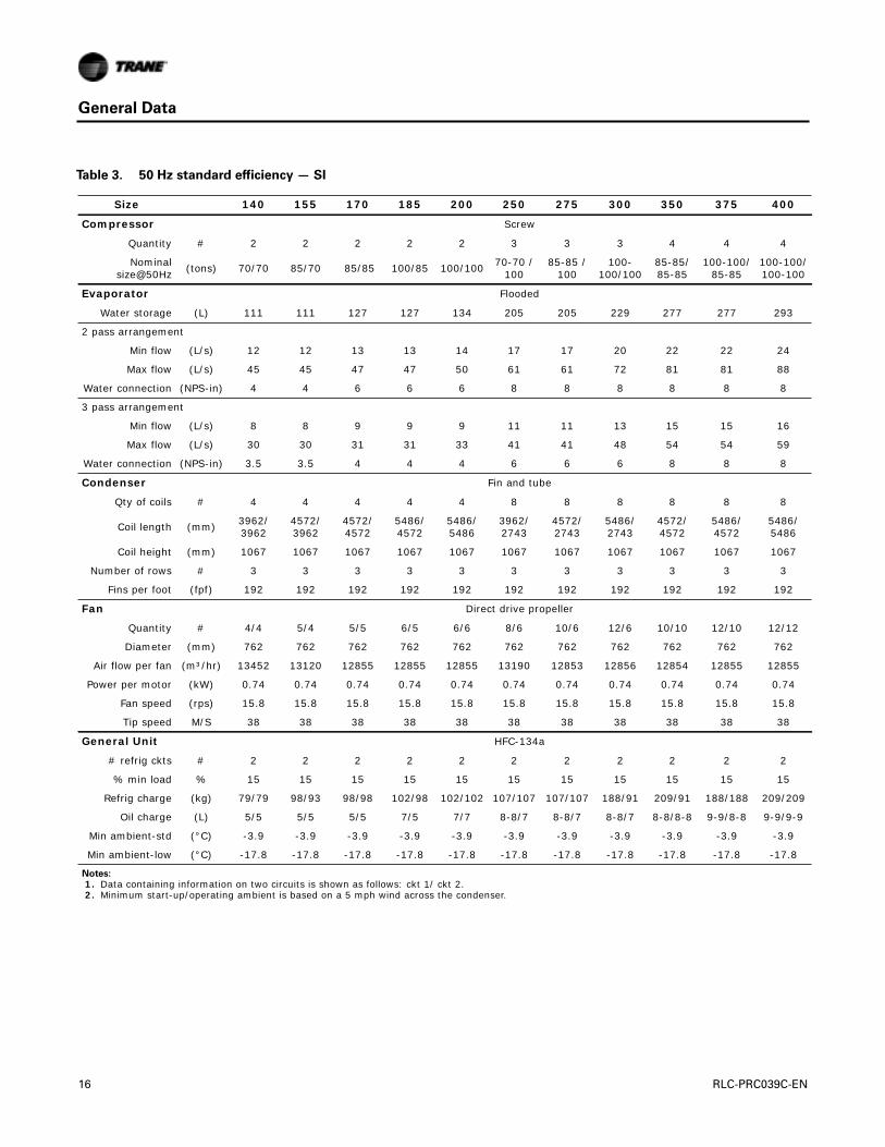
Table 3. 50 Hz standard efficiency — SI
Size 140 155 170 185 200 250 275 300 350 375 400
Compressor Screw
Quantity # 2 2 2 2 2 3 3 3 4 4 4
Nominal size@50Hz (tons) 70/70 85/70 85/85 100/85 100/100 70-70 /
10085-85 /
100100-
100/10085-85/85-85
100-100/85-85
100-100/100-100
Evaporator Flooded
Water storage (L) 111 111 127 127 134 205 205 229 277 277 293
2 pass arrangement
Min flow (L/s) 12 12 13 13 14 17 17 20 22 22 24
Max flow (L/s) 45 45 47 47 50 61 61 72 81 81 88
Water connection (NPS-in) 4 4 6 6 6 8 8 8 8 8 8
3 pass arrangement
Min flow (L/s) 8 8 9 9 9 11 11 13 15 15 16
Max flow (L/s) 30 30 31 31 33 41 41 48 54 54 59
Water connection (NPS-in) 3.5 3.5 4 4 4 6 6 6 8 8 8
Condenser Fin and tube
Qty of coils # 4 4 4 4 4 8 8 8 8 8 8
Coil length (mm) 3962/3962
4572/3962
4572/4572
5486/4572
5486/5486
3962/2743
4572/2743
5486/2743
4572/4572
5486/4572
5486/5486
Coil height (mm) 1067 1067 1067 1067 1067 1067 1067 1067 1067 1067 1067
Number of rows # 3 3 3 3 3 3 3 3 3 3 3
Fins per foot (fpf) 192 192 192 192 192 192 192 192 192 192 192
Fan Direct drive propeller
Quantity # 4/4 5/4 5/5 6/5 6/6 8/6 10/6 12/6 10/10 12/10 12/12
Diameter (mm) 762 762 762 762 762 762 762 762 762 762 762
Air flow per fan (m³/hr) 13452 13120 12855 12855 12855 13190 12853 12856 12854 12855 12855
Power per motor (kW) 0.74 0.74 0.74 0.74 0.74 0.74 0.74 0.74 0.74 0.74 0.74
Fan speed (rps) 15.8 15.8 15.8 15.8 15.8 15.8 15.8 15.8 15.8 15.8 15.8
Tip speed M/S 38 38 38 38 38 38 38 38 38 38 38
General Unit HFC-134a
# refrig ckts # 2 2 2 2 2 2 2 2 2 2 2
% min load % 15 15 15 15 15 15 15 15 15 15 15
Refrig charge (kg) 79/79 98/93 98/98 102/98 102/102 107/107 107/107 188/91 209/91 188/188 209/209
Oil charge (L) 5/5 5/5 5/5 7/5 7/7 8-8/7 8-8/7 8-8/7 8-8/8-8 9-9/8-8 9-9/9-9
Min ambient-std (°C) -3.9 -3.9 -3.9 -3.9 -3.9 -3.9 -3.9 -3.9 -3.9 -3.9 -3.9
Min ambient-low (°C) -17.8 -17.8 -17.8 -17.8 -17.8 -17.8 -17.8 -17.8 -17.8 -17.8 -17.8
Notes:
1. Data containing information on two circuits is shown as follows: ckt 1/ ckt 2. 2. Minimum start-up/operating ambient is based on a 5 mph wind across the condenser.
16 RLC-PRC039C-EN

General Data
Table 4. 50 Hz high efficiency — SI
Size 120 130 140 155 170 185 200 250 275 300 350 375 400
Compressor Screw
Quantity # 2 2 2 2 2 2 2 3 3 3 4 4 4
Nominal size@50Hz (tons) 60/60 70/60 70/70 85/70 85/85 100/
85 100/100
70-70 /100
85-85 /100
100-100/100
85-85 /85-85
100-100/85-85
100-100/100-100
Evaporator Flooded
Water storage (L) 111 111 127 127 134 145 145 229 245 245 293 306 316
2 pass arrangement
Min flow (L/s) 12 12 13 13 14 14 14 20 21 21 24 26 27
Max flow (L/s) 45 45 47 47 50 50 50 72 78 78 88 94 98
Water connection (NPS-in) 4 4 6 6 6 6 6 8 8 8 8 8 8
3 pass arrangement
Min flow (L/s) 8 8 9 9 9 9 9 13 14 14 16 17 18
Max flow (L/s) 30 30 31 31 33 33 33 48 52 52 59 62 65
Water connection (NPS-in) 3.5 3.5 4 4 4 4 4 6 6 6 8 8 8
Condenser Fin and tube
Qty of coils # 4 4 4 4 4 4 4 8 8 8 8 8 8
Coil length (mm) 3962/3962
4572/3962
4572/4572
5486/4572
5486/5486
6400/5486
6400/6400
4572/2743
5486/3657
6400/3657
5486/5486
6400/5486
6400/6400
Coil height (mm) 1067 1067 1067 1067 1067 1067 1067 1067 1067 1067 1067 1067 1067
Number of rows # 3 3 3 3 3 3 3 3 3 3 3 3 3
Fins per foot (fpf) 192 192 192 192 192 192 192 192 192 192 192 192 192
Fan Direct drive propeller
Quantity # 4/4 5/4 5/5 6/5 6/6 7/6 7/7 10/6 12/6 14/6 12/12 14/12 14/14
Diameter (mm) 762 762 762 762 762 762 762 762 762 762 762 762 762
Air flow per fan (m³/hr) 62484 68819 12839 12839 12839 12840 12842 12844 13493 13430 12838 12724 12841
Power per motor (kW) 0.74 0.74 0.74 0.74 0.74 0.74 0.74 0.74 0.74 0.74 0.74 0.74 0.74
Fan speed (rps) 15.8 15.8 15.8 15.8 15.8 15.8 15.8 15.8 15.8 15.8 15.8 15.8 15.8
Tip speed M/S 38 38 38 38 38 38 38 38 38 38 38 38 38
General Unit HFC-134a
# refrig ckts # 2 2 2 2 2 2 2 2 2 2 2 2 2
% min load % 15 15 15 15 15 15 15 15 15 15 15 15 15
Refrig charge (kg) 75/75 79/75 79/79 98/93 98/98 102/95
102/102
166/91
188/91
209/91
188/188
209/188
209/209
Oil charge (L) 5/5 5/5 5/5 5/5 5/5 7/5 7/7 8-8/7
8-8/7
8-8/7
8-8/8-8
9-9/9-9
9-99-9
Min ambient-std (°C) -3.9 -3.9 -3.9 -3.9 -3.9 -3.9 -3.9 -3.9 -3.9 -3.9 -3.9 -3.9 -3.9
Min ambient-low (°C) -17.8 -17.8 -17.8 -17.8 -17.8 -17.8 -17.8 -17.8 -17.8 -17.8 -17.8 -17.8 -17.8
Notes:
1. Data containing information on two circuits is shown as follows: ckt 1/ ckt 2. 2. Minimum start-up/operating ambient is based on a 5 mph wind across the condenser.
RLC-PRC039C-EN 17

Controls
LCDTouch Screen DisplayThe standard DynaView™ display provided with theTracer® CH530 control panel features an LCDtouch screen that is navigated by file tabs.This is an advanced interface that allows the user toaccess any important information concerning setpoints, active temperatures, modes, electricaldata, pressure, and diagnostics. It uses full text display available in 19 languages.
Display Features Include:
• LCD touch screen with LED backlighting, for scrolling access to input and output operatinginformation
• Single screen, folder/tab style display of all available information on individual components(evaporator, condenser, compressor, etc.)
• Password entry/lockout system to enable or disable display
• Automatic and immediate stop capabilities for standard or immediate manual shutdown
• Fast, easy access to available chiller data in tabbed format, including:
• Modes of operation, including normal cooling as well as ice making
• Water temperatures and setpoints
• Loading and limiting status and setpoints
• Outdoor air temperature
• Start/stop differential timers
• Pump status and override
• Chilled water reset settings
• Optional external setpoints, including:
• Chilled water, demand limit, ice building
Reports, listed on a single tabbed screen for easy access, including:
• ASHRAE, containing all guideline 3 report information
• Evaporator, condenser, compressor
Evaporator, condenser, and compressor reports containing all operational information onindividual components, including:
• Water temperatures, refrigerant pressures, temperatures, and approach
• Flow switch status, EXV position, compressor starts and run time
Alarm and diagnostic information, including:
• Flashing alarms with touch screen button for immediate address of alarm condition
• Scrollable list of last ten active diagnostics
• Specific information on applicable diagnostic from list of over one hundred
• Automatic or manual resetting diagnostic types
Adaptive Controls
Adaptive Controls directly sense the control variables that govern the operation of the chiller:evaporator pressure and condenser pressure.When any one of these variables approaches a limitcondition when damage may occur to the unit or shutdown on a safety, Adaptive Controls takescorrective action to avoid shutdown and keep the chiller operating.This happens throughcombined actions of compressor and/or fan staging. Whenever possible, the chiller is allowed tocontinue making chilled water.This keeps cooling capacity available until the problem can besolved. Overall, the safety controls help keep the building or process running and out of trouble.
18 RLC-PRC039C-EN

Controls
Stand Alone Controls
Single chillers installed in applications without a building management system is simple to installand control: only a remote auto/stop for scheduling is required for unit operation. Signals from thechilled water pump contactor auxiliary, or a flow switch, are wired to the chilled water flow interlock.Signals from a time clock or some other remote device are wired to the external auto/stop input.
• External Auto/Stop - A job site provided contact closure will turn the unit on and off.
• Chilled Water Flow Interlock - A job site provided contact closure from a chilled water pumpcontactor or a flow switch is required and will allow unit operation if a load exists.This featurewill allow the unit to run in conjunction with the pump system.
• External Interlock - A job site supplied contact opening wired to this input will turn the unit offand require a manual reset of the unit microcomputer.This closure is typically triggered by ajob site supplied system such as a fire alarm.
• Chilled Water Pump Control - Unit controls provide an output to control the chilled waterpump(s). One contact closure to the chiller is all that is required to initiate the chilled watersystem. Chilled water pump control by the chiller is a requirement on the Air-Cooled Series R.
• Chilled WaterTemperature Reset -The reset can be based on return water temperature oroutdoor air temperature.
Hardwire Points
Microcomputer controls allow simple interface with other control systems, such as time clocks,building automation systems, and ice storage systems via hardwire points.This means you havethe flexibility to meet job requirements while not having to learn a complicated control system.
Remote devices are wired from the control panel to provide auxiliary control to a buildingautomation system. Inputs and outputs can be communicated via a typical 4–20 mA electricalsignal, an equivalent 2–10 Vdc signal, or by utilizing contact closures. Contact closures may beused to trigger job site supplied alarm lights or alarm bells.
This setup has the same features as a stand alone water chiller, with the possibility of havingadditional optional features:
• Circuit enable/disable
• Ice making enable/status
• External chilled water setpoint, external demand limit setpoint
• Alarm indication contacts provides three single pole double throw contact closures toindicate: compressor on/off status, compressor running at maximum capacity, failure hasoccurred (ckt 1/ckt 2)
BACnet® Interface
BACnet® interface capabilities are available, with communication link via single twisted-pair wiringto a factory-installed and tested communication board.
Required features:
• BACnet® Interface (selectable option with chiller)
BACnet® is a data communication protocol for building automation and control networksdeveloped by American Society of Heating, Refrigerating and Air-Conditioning Engineers(ASHRAE).
LonTalk® LCI-C Interface
LonTalk® (LCI-C) communications capabilities are available, with communication link via singletwisted pair wiring to factory installed, tested communication board.
• Required features: LonTalk®/Tracer® Summit Interface (selectable option with chiller)
RLC-PRC039C-EN 19
Controls
LonTalk® is a communications protocol developed by the Echelon™ Corporation.The LONMARK®
association develops control profiles using the LonTalk communication protocol. LonTalk is a unitlevel communications protocol.
LonTalk® Communications Interface for Chillers (LCI-C) provides a generic automation system withthe LONMARK® chiller profile inputs/outputs. In addition to the standard points,Trane provides othercommonly used network output variables for greater interoperability with any automation system.The complete reference list ofTrane LonTalk® points is available on the LONMARK® web site.
Trane controls or another vendor’s system can use the predefined list of points with ease to givethe operator a complete picture of how the system is running
Tracer® Summit
The chiller plant control capabilities of theTraneTracer® Summit building automation system areunequaled in the industry.Trane’s depth of experience in chillers and controls makes us a wellqualified choice for automation of chiller plants using air-cooled chillers. Our chiller plantautomation software is fully pre-engineered and tested.
Required features:
• LonTalk®/Tracer® Summit Interface (selectable option with chiller)
• Building Control Unit (external device required)
Energy Efficiency
• Sequences starting of chillers to optimize the overall chiller plant energy efficiency
– Individual chillers operate as base, peak, or swing based on capacity and efficiency
– Automatically rotates individual chiller operation to equalize runtime and wearbetween chillers.
– Evaluates and selects the lowest energy consumption alternative from an overallsystem perspective.
Easy Operation and Maintenance
• Remote monitoring and control
• Displays both current operation conditions and scheduled automated control actions
• Concise reports assist in planning for preventative maintenance and verifying performance
• Alarm notification and diagnostic messages aid in quick and accurate troubleshooting
Tracer® SC
TheTracer® SC system controller acts as the central coordinator for all individual equipmentdevices on aTracer building automation system.TheTracer® SC scans all unit controllers to updateinformation and coordinate building control, including building subsystems such as VAV andchiller water systems. With this system option, the full breadth ofTrane’s HVAC and controlsexperience are applied to offer solutions to many facility issues.The LAN allows building operatorsto manage these varied components as one system from any personal computer with web access.The benefits of this system are:
• Improved usability with automatic data collection, enhanced data logging, easier to creategraphics, simpler navigation, pre-programmed scheduling, reporting, and alarm logs.
• Flexible technology allows for system sizes from 30-120 unit controllers with any combinationof LonTalk® or BACnet® unit controllers.
• LEED certification through site commissioning report, energy data collection measurement,optimizing energy performance, and maintaining indoor air quality.
• Energy savings programs include: fan pressure optimization, ventilation reset, and chiller plantcontrol (adds and subtracts chillers to meet cooling loads).
20 RLC-PRC039C-EN
7 /
0
0
0
0
0
0
0
0
0
0
0
s
is
.
Electrical Data
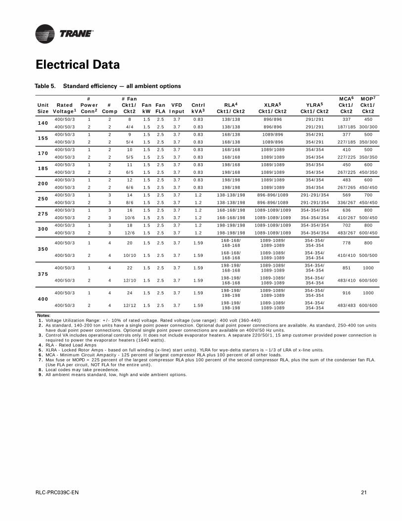
Table 5. Standard efficiency — all ambient options
Unit Size
Rated Voltage1
# Power Conn2
#Comp
# Fan Ckt1/Ckt2
Fan kW
Fan FLA
VFD Input
Cntrl kVA3
RLA4
Ckt1/Ckt2XLRA5
Ckt1/Ckt2YLRA5
Ckt1/Ckt2
MCA6 Ckt1/Ckt2
MOPCkt1Ckt2
140400/50/3 1 2 8 1.5 2.5 3.7 0.83 138/138 896/896 291/291 337 450
400/50/3 2 2 4/4 1.5 2.5 3.7 0.83 138/138 896/896 291/291 187/185 300/30
155400/50/3 1 2 9 1.5 2.5 3.7 0.83 168/138 1089/896 354/291 377 500
400/50/3 2 2 5/4 1.5 2.5 3.7 0.83 168/138 1089/896 354/291 227/185 350/30
170400/50/3 1 2 10 1.5 2.5 3.7 0.83 168/168 1089/1089 354/354 410 500
400/50/3 2 2 5/5 1.5 2.5 3.7 0.83 168/168 1089/1089 354/354 227/225 350/35
185400/50/3 1 2 11 1.5 2.5 3.7 0.83 198/168 1089/1089 354/354 450 600
400/50/3 2 2 6/5 1.5 2.5 3.7 0.83 198/168 1089/1089 354/354 267/225 450/35
200400/50/3 1 2 12 1.5 2.5 3.7 0.83 198/198 1089/1089 354/354 483 600
400/50/3 2 2 6/6 1.5 2.5 3.7 0.83 198/198 1089/1089 354/354 267/265 450/45
250400/50/3 1 3 14 1.5 2.5 3.7 1.2 138-138/198 896-896/1089 291-291/354 569 700
400/50/3 2 3 8/6 1.5 2.5 3.7 1.2 138-138/198 896-896/1089 291-291/354 336/267 450/45
275400/50/3 1 3 16 1.5 2.5 3.7 1.2 168-168/198 1089-1089/1089 354-354/354 636 800
400/50/3 2 3 10/6 1.5 2.5 3.7 1.2 168-168/198 1089-1089/1089 354-354/354 410/267 500/45
300400/50/3 1 3 18 1.5 2.5 3.7 1.2 198-198/198 1089-1089/1089 354-354/354 702 800
400/50/3 2 3 12/6 1.5 2.5 3.7 1.2 198-198/198 1089-1089/1089 354-354/354 483/267 600/45
350400/50/3 1 4 20 1.5 2.5 3.7 1.59 168-168/
168-1681089-1089/1089-1089
354-354/354-354 778 800
400/50/3 2 4 10/10 1.5 2.5 3.7 1.59 168-168/168-168
1089-1089/1089-1089
354-354/354-354 410/410 500/50
375400/50/3 1 4 22 1.5 2.5 3.7 1.59 198-198/
168-1681089-1089/1089-1089
354-354/354-354 851 1000
400/50/3 2 4 12/10 1.5 2.5 3.7 1.59 198-198/168-168
1089-1089/1089-1089
354-354/354-354 483/410 600/50
400400/50/3 1 4 24 1.5 2.5 3.7 1.59 198-198/
198-1981089-1089/1089-1089
354-354/354-354 916 1000
400/50/3 2 4 12/12 1.5 2.5 3.7 1.59 198-198/198-198
1089-1089/1089-1089
354-354/354-354 483/483 600/60
Notes:
1. Voltage Utilization Range: +/- 10% of rated voltage. Rated voltage (use range): 400 volt (360-440) 2. As standard, 140-200 ton units have a single point power connection. Optional dual point power connections are available. As standard, 250-400 ton unit
have dual point power connections. Optional single point power connections are available on 400V/50 Hz units. 3. Control VA includes operational controls only. It does not include evaporator heaters. A separate 220/50/1, 15 amp customer provided power connection
required to power the evaporator heaters (1640 watts). 4. RLA - Rated Load Amps 5. XLRA - Locked Rotor Amps - based on full winding (x-line) start units). YLRA for wye-delta starters is ~1/3 of LRA of x-line units. 6. MCA - Minimum Circuit Ampacity - 125 percent of largest compressor RLA plus 100 percent of all other loads. 7. Max fuse or MOPD = 225 percent of the largest compressor RLA plus 100 percent of the second compressor RLA, plus the sum of the condenser fan FLA
(Use FLA per circuit, NOT FLA for the entire unit). 8. Local codes may take precedence. 9. All ambient means standard, low, high and wide ambient options.
RLC-PRC039C-EN 21

Electrical Data
0
0
0
0
0
0
0
0
0
0
0
0
0
its
is
.
Table 6. High efficiency — standard and low ambient options
Unit Size
Rated Voltage1
# Power Conn2
#Comp
# Fan Ckt1/Ckt2
Fan kW
Fan FLA
VFD Input
Cntrl kVA3
RLA4
Ckt1/Ckt2XLRA5
Ckt1/Ckt2YLRA5
Ckt1/Ckt2
MCA6 Ckt1/Ckt2
MOP7
Ckt1/Ckt2
120400/50/3 1 2 8 1.5 2.5 3.7 0.83 113/113 796/796 259/259 280 350
400/50/3 2 2 4/4 1.5 2.5 3.7 0.83 113/113 796/796 259/259 155/153 250/25
130400/50/3 1 2 9 1.5 2.5 3.7 0.83 132/113 896/796 291/259 307 400
400/50/3 2 2 5/4 1.5 2.5 3.7 0.83 132/113 896/796 291/259 182/153 300/25
140400/50/3 1 2 10 1.5 2.5 3.7 0.83 132/132 896/896 291/291 329 450
400/50/3 2 2 5/5 1.5 2.5 3.7 0.83 132/132 896/896 291/291 182/180 300/30
155400/50/3 1 2 11 1.5 2.5 3.7 0.83 160/132 1089/896 354/291 367 500
400/50/3 2 2 6/5 1.5 2.5 3.7 0.83 160/132 1089/896 354/291 220/180 350/30
170400/50/3 1 2 12 1.5 2.5 3.7 0.83 160/160 1089/1089 354/354 397 500
400/50/3 2 2 6/6 1.5 2.5 3.7 0.83 160/160 1089/1089 354/354 220/218 350/35
185400/50/3 1 2 13 1.5 2.5 3.7 0.83 189/160 1089/1089 354/354 436 600
400/50/3 2 2 7/6 1.5 2.5 3.7 0.83 189/160 1089/1089 354/354 259/218 400/35
200400/50/3 1 2 14 1.5 2.5 3.7 0.83 189/189 1089/1089 354/354 468 600
400/50/3 2 2 7/7 1.5 2.5 3.7 0.83 189/189 1089/1089 354/354 259/257 400/40
250400/50/3 1 3 16 1.5 2.5 3.7 1.2 132-132/189 896-896/1089 291-291/354 553 700
400/50/3 2 3 10/6 1.5 2.5 3.7 1.2 132-132/189 896-896/1089 291-291/354 329/256 450/40
275400/50/3 1 3 18 1.5 2.5 3.7 1.2 160-160/189 1089-1089/1089 354-354/354 614 800
400/50/3 2 3 12/6 1.5 2.5 3.7 1.2 160-160/189 1089-1089/1089 354-354/354 397/256 500/40
300400/50/3 1 3 20 1.5 2.5 3.7 1.2 189-189/189 1089-1089/1089 354-354/354 677 800
400/50/3 2 3 14/6 1.5 2.5 3.7 1.2 189-189/189 1089-1089/1089 354-354/354 468/256 600/40
350400/50/3 1 4 24 1.5 2.5 3.7 1.2 160-160/
160-1601089-1089/1089-1089
354-354/354-354 755 800
400/50/3 2 4 12/12 1.5 2.5 3.7 1.2 160-160/160-160
1089-1089/1089-1089
354-354/354-354 397/397 500/50
375400/50/3 1 4 26 1.5 2.5 3.7 1.59 189-189/
160-1601089-1089/1089-1089
354-354/354-354 826 1000
400/50/3 2 4 14/12 1.5 2.5 3.7 1.59 189-189/160-160
1089-1089/1089-1089
354-354/354-354 468/397 600/50
400400/50/3 1 4 28 1.5 2.5 3.7 1.59 189-189/
189-1891089-1089/1089-1089
354-354/354-354 889 1000
400/50/3 2 4 14/14 1.5 2.5 3.7 1.59 189-189/189-189
1089-1089/1089-1089
354-354/354-354 468/468 600/60
Notes:
1. Voltage Utilization Range: +/- 10% of rated voltage. Rated voltage (use range): 400 volt (360-440) 2. As standard, 140-200 ton units have a single point power connection. Optional dual point power connections are available. As standard, 250-400 ton un
have dual point power connections. Optional single point power connections are available on 400V/50 Hz units. 3. Control VA includes operational controls only. It does not include evaporator heaters. A separate 220/50/1, 15 amp customer provided power connection
required to power the evaporator heaters (1640 watts). 4. RLA - Rated Load Amps 5. XLRA - Locked Rotor Amps - based on full winding (x-line) start units). YLRA for wye-delta starters is ~1/3 of LRA of x-line units. 6. MCA - Minimum Circuit Ampacity - 125 percent of largest compressor RLA plus 100 percent of all other loads. 7. Max fuse or MOPD = 225 percent of the largest compressor RLA plus 100 percent of the second compressor RLA, plus the sum of the condenser fan FLA
(Use FLA per circuit, NOT FLA for the entire unit). 8. Local codes may take precedence. 9. All ambient means standard, low, high and wide ambient options.
22 RLC-PRC039C-EN

Electrical Data
Table 7. High efficiency — high and wide ambient options
Unit Size
Rated Voltage1
# Power Conn2
#Comp
# Fan Ckt1/Ckt2
Fan kW
Fan FLA
VFD Input
Cntrl kVA3
RLA4
Ckt1/Ckt2XLRA5
Ckt1/Ckt2YLRA5
Ckt1/Ckt2
MCA6 Ckt1/Ckt2
MOP7 Ckt1/Ckt2
120400/50/3 1 2 8 1.5 2.8 3.7 0.83 118/118 796/796 259/259 292 400
400/50/3 2 2 4/4 1.5 2.8 3.7 0.83 118/118 796/796 259/259 162/160 250/250
130400/50/3 1 2 9 1.5 2.8 3.7 0.83 138/118 896/796 291/259 320 450
400/50/3 2 2 5/4 1.5 2.8 3.7 0.83 138/118 896/796 291/259 189/160 300/250
140400/50/3 1 2 10 1.5 2.8 3.7 0.83 138/138 896/896 291/291 342 450
400/50/3 2 2 5/5 1.5 2.8 3.7 0.83 138/138 896/896 291/291 189/187 300/300
155400/50/3 1 2 11 1.5 2.8 3.7 0.83 168/138 1089/896 354/291 383 500
400/50/3 2 2 6/5 1.5 2.8 3.7 0.83 168/138 1089/896 354/291 230/187 350/300
170400/50/3 1 2 12 1.5 2.8 3.7 0.83 168/168 1089/1089 354/354 415 500
400/50/3 2 2 6/6 1.5 2.8 3.7 0.83 168/168 1089/1089 354/354 230/228 350/350
185400/50/3 1 2 13 1.5 2.8 3.7 0.83 198/168 1089/1089 354/354 456 600
400/50/3 2 2 7/6 1.5 2.8 3.7 0.83 198/168 1089/1089 354/354 270/228 450/350
200400/50/3 1 2 14 1.5 2.8 3.7 0.83 198/198 1089/1089 354/354 489 600
400/50/3 2 2 7/7 1.5 2.8 3.7 0.83 198/198 1089/1089 354/354 270/268 450/450
250400/50/3 1 3 16 1.5 2.8 3.7 1.2 138-138/198 896-896/1089 291-291/354 575 700
400/50/3 2 3 10/6 1.5 2.8 3.7 1.2 138-138/198 896-896/1089 291-291/354 342/267 450/450
275400/50/3 1 3 18 1.5 2.8 3.7 1.2 168-168/198 1089-1089/1089 354-354/354 642 800
400/50/3 2 3 12/6 1.5 2.8 3.7 1.2 168-168/198 1089-1089/1089 354-354/354 416/267 500/450
300400/50/3 1 3 20 1.5 2.8 3.7 1.2 198-198/198 1089-1089/1089 354-354/354 706 800
400/50/3 2 3 14/6 1.5 2.8 3.7 1.2 198-198/198 1089-1089/1089 354-354/354 489/267 600/450
350400/50/3 1 4 24 1.5 2.8 3.7 1.59 168-168/
168-1681089-1089/1089-1089
354-354/354-354 789 800
400/50/3 2 4 12/12 1.5 2.8 3.7 1.59 168-168/168-168
1089-1089/1089-1089
354-354/354-354 415/415 500/500
375400/50/3 1 4 26 1.5 2.8 3.7 1.59 198-198/
168-1681089-1089/1089-1089
354-354/354-354 862 1000
400/50/3 2 4 14/12 1.5 2.8 3.7 1.59 198-198/168-168
1089-1089/1089-1089
354-354/354-354 489/415 600/500
400400/50/3 1 4 28 1.5 2.8 3.7 1.59 198-198/
198-1981089-1089/1089-1089
354-354/354-354 928 1000
400/50/3 2 4 14/14 1.5 2.8 3.7 1.59 198-198/198-198
1089-1089/1089-1089
354-354/354-354 489/489 600/600
Notes:
1. Voltage Utilization Range: +/- 10% of rated voltage. Rated voltage (use range): 400 volt (360-440) 2. As standard, 140-200 ton units have a single point power connection. Optional dual point power connections are available. As standard, 250-400 ton units
have dual point power connections. Optional single point power connections are available on 400V/50 Hz units. 3. Control VA includes operational controls only. It does not include evaporator heaters. A separate 220/50/1, 15 amp customer provided power connection
is required to power the evaporator heaters (1640 watts). 4. RLA - Rated Load Amps 5. XLRA - Locked Rotor Amps - based on full winding (x-line) start units). YLRA for wye-delta starters is ~1/3 of LRA of x-line units. 6. MCA - Minimum Circuit Ampacity - 125 percent of largest compressor RLA plus 100 percent of all other loads. 7. Max fuse or MOPD = 225 percent of the largest compressor RLA plus 100 percent of the second compressor RLA, plus the sum of the condenser fan FLA.
(Use FLA per circuit, NOT FLA for the entire unit). 8. Local codes may take precedence. 9. All ambient means standard, low, high and wide ambient options.
RLC-PRC039C-EN 23

Electrical Data
Table 8. Customer wire selection — standard efficiency
Single point power Dual point power - Ckt 1 Dual point power - Ckt 2Unit Size Volt Term Disc
Circuit Breaker Term Disc
Circuit Breaker Term Disc
Circuit Breaker
140 400 (2) 4 AWG - 500 MCM
(2) 2/0 - 500 MCM
(2) 2/0 - 500 MCM
4 AWG - 500 MCM
(1) 1 AWG - 600 MCM or (2) 1 AWG -
250 MCM
(1) 1 AWG - 600 MCM or (2) 1 AWG -
250 MCM
4 AWG - 500 MCM
(1) 1 AWG - 600 MCM or (2) 1 AWG -
250 MCM
(1) 1 AWG - 600 MCM or (2) 1 AWG -
250 MCM
155 400 (2) 4 AWG - 500 MCM
(2) 2/0 - 500 MCM
(2) 2/0 - 500 MCM
4 AWG - 500 MCM
(1) 1 AWG - 600 MCM or (2) 1 AWG -
250 MCM
(1) 1 AWG - 600 MCM or (2) 1 AWG -
250 MCM
4 AWG - 500 MCM
(1) 1 AWG - 600 MCM or (2) 1 AWG -
250 MCM
(1) 1 AWG - 600 MCM or (2) 1 AWG -
250 MCM
170 400 (2) 4 AWG - 500 MCM
(2) 2/0 - 500 MCM
(2) 2/0 - 500 MCM
4 AWG - 500 MCM
(1) 1 AWG - 600 MCM or (2) 1 AWG -
250 MCM
(1) 1 AWG - 600 MCM or (2) 1 AWG -
250 MCM
4 AWG - 500 MCM
(1) 1 AWG - 600 MCM or (2) 1 AWG -
250 MCM
(1) 1 AWG - 600 MCM or (2) 1 AWG -
250 MCM
185 400 (2) 4 AWG - 500 MCM
(2) 2/0 - 500 MCM
(2) 2/0 - 500 MCM
4 AWG - 500 MCM
(2) 2/0 - 500 MCM
(2) 2/0 - 500 MCM
4 AWG - 500 MCM
(1) 1 AWG - 600 MCM or (2) 1 AWG -
250 MCM
(1) 1 AWG - 600 MCM or (2) 1 AWG -
250 MCM
200 400 (2) 4 AWG - 500 MCM
(2) 2/0 - 500 MCM
(2) 2/0 - 500 MCM
4 AWG - 500 MCM
(2) 2/0 - 500 MCM
(2) 2/0 - 500 MCM
4 AWG - 500 MCM
(2) 2/0 - 500 MCM
(2) 2/0 - 500 MCM
250 400 (2) 4 AWG - 500 MCM
(3) 3/0 - 500 MCM
(3) 3/0 - 500 MCM
(2) 4 AWG - 500 MCM
(2) 2/0 - 500 MCM
(2) 2/0 - 500 MCM
4 AWG - 500 MCM
(2) 2/0 - 500 MCM
(2) 2/0 - 500 MCM
275 400 n/a (4) 2 AWG - 600 MCM
(2) 4 AWG - 500 MCM
(2) 2/0 - 500 MCM
(2) 2/0 - 500 MCM
4 AWG - 500 MCM
(2) 2/0 - 500 MCM
(2) 2/0 - 500 MCM
300 400 n/a (4) 2 AWG - 600 MCM
(2) 4 AWG - 500 MCM
(2) 2/0 - 500 MCM
(2) 2/0 - 500 MCM
4 AWG - 500 MCM
(2) 2/0 - 500 MCM
(2) 2/0 - 500 MCM
350 400 n/a (4) 2 AWG - 600 MCM
(2) 4 AWG - 500 MCM
(2) 2/0 - 500 MCM
(2) 2/0 - 500 MCM
(2) 4 AWG - 500 MCM
(2) 2/0 - 500 MCM
(2) 2/0 - 500 MCM
375 400 n/a (4) 2 AWG - 600 MCM
(2) 4 AWG - 500 MCM
(2) 2/0 - 500 MCM
(2) 2/0 - 500 MCM
(4) 2 AWG - 600 MCM
(2) 2/0 - 500 MCM
(2) 2/0 - 500 MCM
400 400 n/a (4) 2 AWG - 600 MCM
(2) 4 AWG - 500 MCM
(2) 2/0 - 500 MCM
(2) 2/0 - 500 MCM
(2) 4 AWG - 500 MCM
(2) 2/0 - 500 MCM
(2) 2/0 - 500 MCM
Notes:
1. Non-fused unit disconnect and circuit breaker are optional. 2. Copper wire only, based on nameplate minimum circuit ampacity (MCA). 3. Circuit breaker sizes are for factory mounted only. 4. n/a - not available
24 RLC-PRC039C-EN

Electrical Data
Table 9. Customer wire selection — high efficiency
Ambient
Single point power Dual point power - Ckt 1 Dual point power - Ckt 2
Unit Size Volt Term Disc
Circuit Breaker Term Disc
Circuit Breaker Term Disc
Circuit Breaker
120 400 All 4 AWG - 500 MCM
(1) 1 AWG - 600 MCM or (2) 1 AWG -
250 MCM
(1) 1 AWG - 600 MCM or (2) 1 AWG -
250 MCM
4 AWG - 500 MCM
3/0-350MCM
3/0-350MCM
4 AWG - 500 MCM
3/0-350MCM
3/0-350MCM
130
400 Std, Low 4 AWG - 500 MCM
(1) 1 AWG - 600 MCM or (2) 1 AWG -
250 MCM
(1) 1 AWG - 600 MCM or (2) 1 AWG -
250 MCM
4 AWG - 500 MCM
3/0-350MCM
3/0-350MCM
4 AWG - 500 MCM
3/0-350MCM
3/0-350MCM
400 High, Wide 4 AWG - 500 MCM
(2) 2/0 - 500 MCM
(2) 2/0 - 500 MCM
4 AWG - 500 MCM
(1) 1 AWG - 600 MCM or (2) 1 AWG -
250 MCM
(1) 1 AWG - 600 MCM or
(2) 1 AWG - 250 MCM
4 AWG - 500 MCM
3/0-350MCM
3/0-350MCM
140 400 All (2) 4 AWG - 500 MCM
(2) 2/0 - 500 MCM
(2) 2/0 - 500 MCM
4 AWG - 500 MCM
(1) 1 AWG - 600 MCM or (2) 1 AWG -
250 MCM
(1) 1 AWG - 600 MCM or(2) 1 AWG -
250 MCM
4 AWG -500 MCM
(1) 1 AWG - 600 MCM or (2) 1 AWG -
250 MCM
(1) 1 AWG - 600 MCM or (2) 1 AWG -
250 MCM
155 400 All (2) 4 AWG - 500 MCM
(2) 2/0 - 500 MCM
(2) 2/0 - 500 MCM
4 AWG - 500 MCM
(1) 1 AWG - 600 MCM or (2) 1 AWG -
250 MCM
(1) 1 AWG - 600 MCM or (2) 1 AWG -
250 MCM
4 AWG - 500 MCM
(1) 1 AWG - 600 MCM or (2) 1 AWG -
250 MCM
(1) 1 AWG - 600 MCM or (2) 1 AWG -
250 MCM
170
400 Std, Low (2) 4 AWG - 500 MCM
(2) 2/0 - 500 MCM
(2) 2/0 -500 MCM
4 AWG - 500 MCM
(1) 1 AWG - 600 MCM or (2) 1 AWG -
250 MCM
(1) 1 AWG - 600 MCM or (2) 1 AWG -
250 MCM
4 AWG - 500 MCM
(1) 1 AWG - 600 MCM or (2) 1 AWG -
250 MCM
(1) 1 AWG - 600 MCM or (2) 1 AWG -
250 MCM
400 High, Wide (2) 4 AWG - 500 MCM
(2) 2/0 - 500 MCM
(2) 2/0 - 0 MCM
4 AWG -500 MCM
(1) 1 AWG - 600 MCM or (2) 1 AWG -
250 MCM
(1) 1 AWG - 600 MCM or(2) 1 AWG -
250 MCM
4 AWG - 500 MCM
(1) 1 AWG - 600 MCM or (2) 1 AWG -
250 MCM
(1) 1 AWG - 600 MCM or (2) 1 AWG -
250 MCM
185
400 Std, Low (2) 4 AWG - 500 MCM
(2) 2/0 -500 MCM
(2) 2/0 - 500 MCM
4 AWG -500 MCM
(1) 1 AWG - 600 MCM or (2) 1 AWG -
250 MCM
(1) 1 AWG -600 MCM or(2) 1 AWG -
250 MCM
4 AWG - 500 MCM
(1) 1 AWG - 600 MCM or (2) 1 AWG -
250 MCM
(1) 1 AWG - 600 MCM or (2) 1 AWG -
250 MCM
400 High, Wide (2) 4 AWG - 500 MCM
(2) 2/0 -500 MCM
(2) 2/0 - 500 MCM
4 AWG - 500 MCM
(2) 2/0 - 500 MCM
(2) 2/0 -500 MCM
4 AWG - 500 MCM
(1) 1 AWG - 600 MCM or (2) 1 AWG -
250 MCM
(1) 1 AWG - 600 MCM or (2) 1 AWG -
250 MCM
200
400 Std, Low (2) 4 AWG - 500 MCM
(2) 2/0 - 500 MCM
(2) 2/0 - 500 MCM
4 AWG - 500 MCM
(1) 1 AWG - 600 MCM or (2) 1 AWG -
250 MCM
(1) 1 AWG - 600 MCM or (2) 1 AWG -
250 MCM
4 AWG -500 MCM
(1) 1 AWG - 600 MCM or (2) 1 AWG -
250 MCM
(1) 1 AWG - 600 MCM or (2) 1 AWG -
250 MCM
400 High, Wide (2) 4 AWG - 500 MCM
(2) 2/0 - 500 MCM
(2) 2/0 - 500 MCM
4 AWG - 500 MCM
(2) 2/0 - 500 MCM
(2) 2/0 - 500 MCM
4 AWG - 500 MCM
(1) 1 AWG - 600 MCM or (2) 1 AWG -
250 MCM
(1) 1 AWG - 600 MCM or (2) 1 AWG -
250 MCM
250400 Std, Low (2) 4 AWG -
500 MCM(3) 3/0 -500 MCM
(3) 3/0 - 500 MCM
4 AWG - 500 MCM
(2) 2/0 -500 MCM
(2) 2/0 -500 MCM
4 AWG -500 MCM
(1) 1 AWG - 600 MCM or (2) 1 AWG -
250 MCM
(1) 1 AWG - 600 MCM or (2) 1 AWG -
250 MCM
400 High, Wide (2) 4 AWG - 500 MCM
(3) 3/0 -500 MCM
(3) 3/0 - 500 MCM
4 AWG - 500 MCM
(2) 2/0 -500 MCM
(2) 2/0 - 500 MCM
4 AWG - 500 MCM
(2) 2/0 - 500 MCM
(2) 2/0 -500 MCM
275 400 All n/a (4) 2 AWG - 600 MCM
(2) 4 AWG - 500 MCM
(2) 2/0 - 500 MCM
(2) 2/0 - 500 MCM
4 AWG - 500 MCM
(1) 1 AWG - 600 MCM or (2) 1 AWG -
250 MCM
(1) 1 AWG - 600 MCM or (2) 1 AWG -
250 MCM
RLC-PRC039C-EN 25

Electrical Data
300 400 All n/a (4) 2 AWG - 600 MCM
(2) 4 AWG - 500 MCM
(2) 2/0 -500 MCM
(2) 2/0 - 500 MCM
4 AWG - 500 MCM
(1) 1 AWG - 600 MCM or (2) 1 AWG -
250 MCM
(1) 1 AWG - 600 MCM or (2) 1 AWG -
250 MCM
350 400 All n/a (4) 2 AWG - 600 MCM
(2) 4 AWG - 500 MCM
(2) 2/0 - 500 MCM
(2) 2/0 - 500 MCM
(2) 4 AWG - 500 MCM
(2) 2/0 - 500 MCM
(2) 2/0 - 500 MCM
375 400B All n/a (4) 2 AWG - 600 MCM
(2) 4 AWG - 500 MCM
(2) 2/0 - 500 MCM
(2) 2/0 -500 MCM
(4) 2 AWG - 600 MCM
(2) 2/0 -500 MCM
(2) 2/0 -500 MCM
400 400 All n/a (4) 2 AWG - 600 MCM
(2) 4 AWG - 500 MCM
(2) 2/0 - 500 MCM
(2) 2/0 - 500 MCM
(2) 4 AWG - 500 MCM
(2) 2/0 - 500 MCM
(2) 2/0 -500 MCM
Notes:
1. Non-fused unit disconnect and circuit breaker are optional. 2. Copper wire only, based on nameplate minimum circuit ampacity (MCA). 3. Circuit breaker sizes are for factory mounted only. 4. n/a - not available
Table 9. Customer wire selection — high efficiency (continued)
Ambient
Single point power Dual point power - Ckt 1 Dual point power - Ckt 2
Unit Size Volt Term Disc
Circuit Breaker Term Disc
Circuit Breaker Term Disc
Circuit Breaker
26 RLC-PRC039C-EN

Electrical Data
Page left intentionally blank
RLC-PRC039C-EN 27

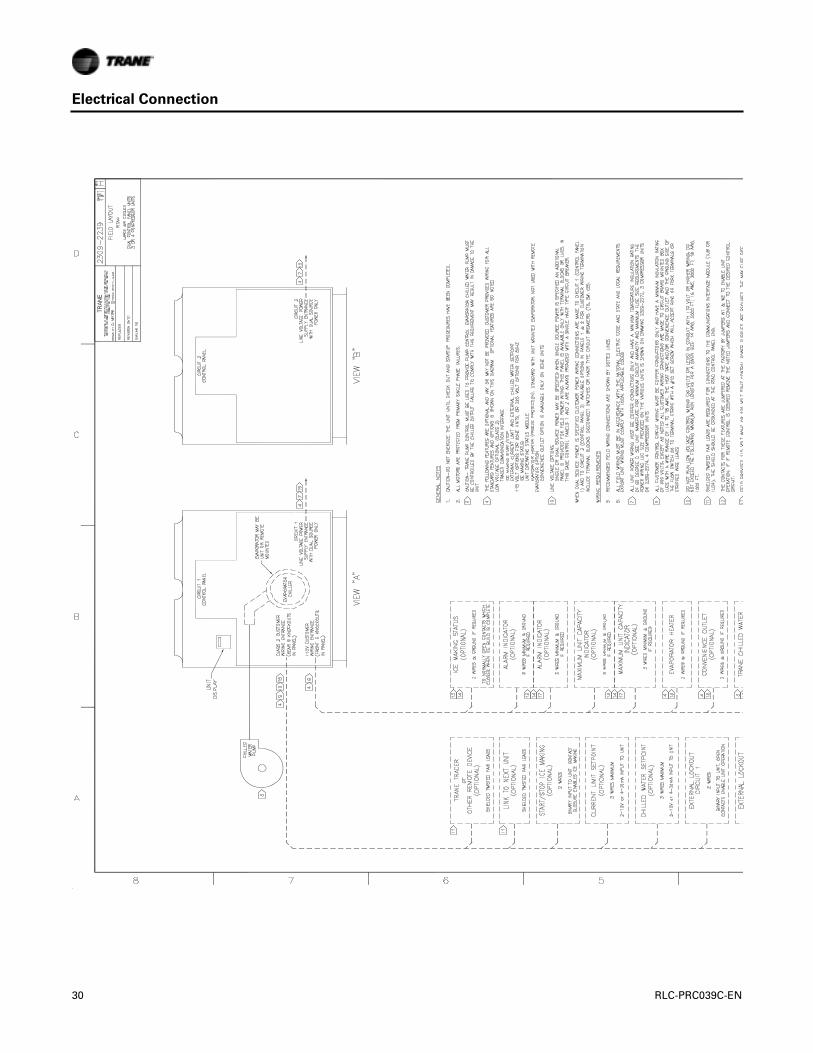
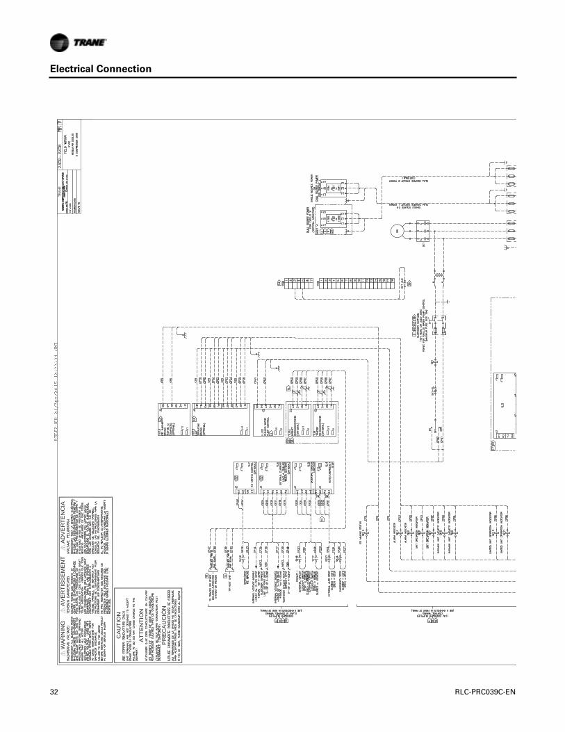
Electrical Connection
Rel
ease
on
4/25
/2
28 RLC-PRC039C-EN

Electrical Connection
RLC-PRC039C-EN 29
Electrical Connection
30 RLC-PRC039C-EN

Electrical Connection
RLC-PRC039C-EN 31
Electrical Connection
RELEASED21/Apr/201512:33:34GMT
RELEASED21/Apr/201512:33:34GMT
2
32 RLC-PRC039C-EN

Electrical Connection
RLC-PRC039C-EN 33

Electrical Connection
34 RLC-PRC039C-EN

Electrical Connection
RLC-PRC039C-EN 35

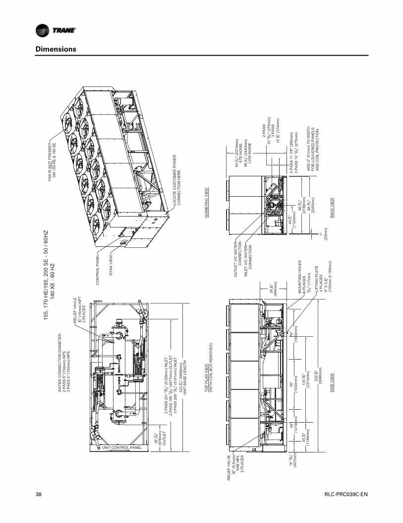
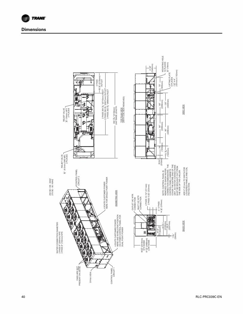
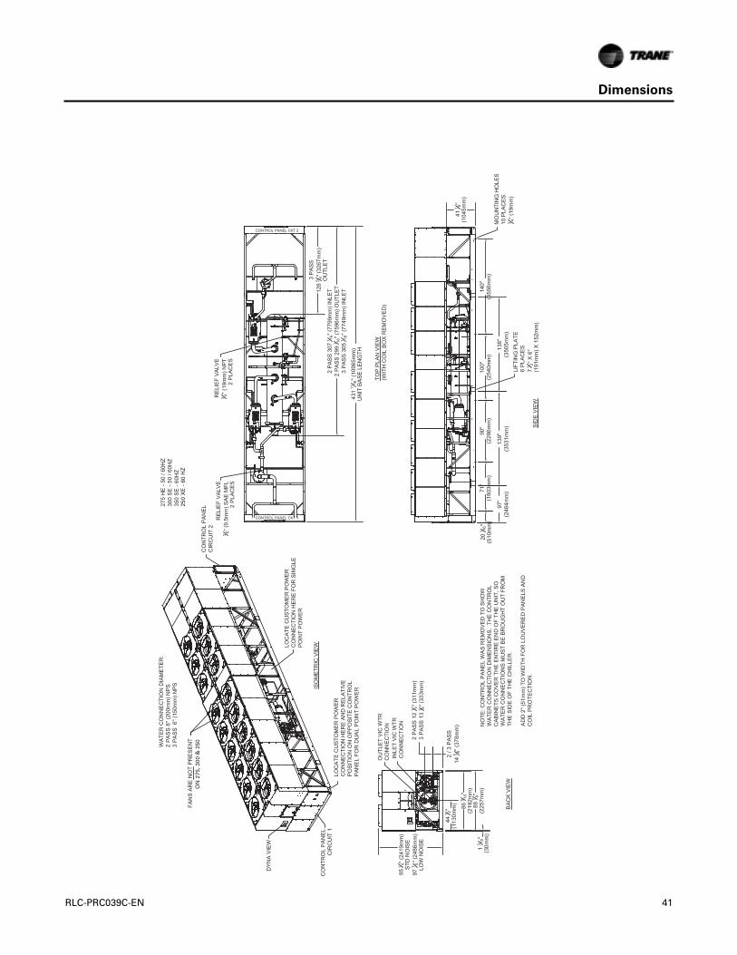
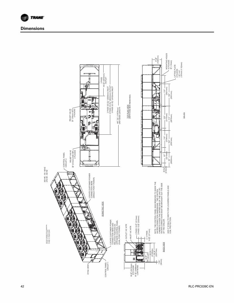
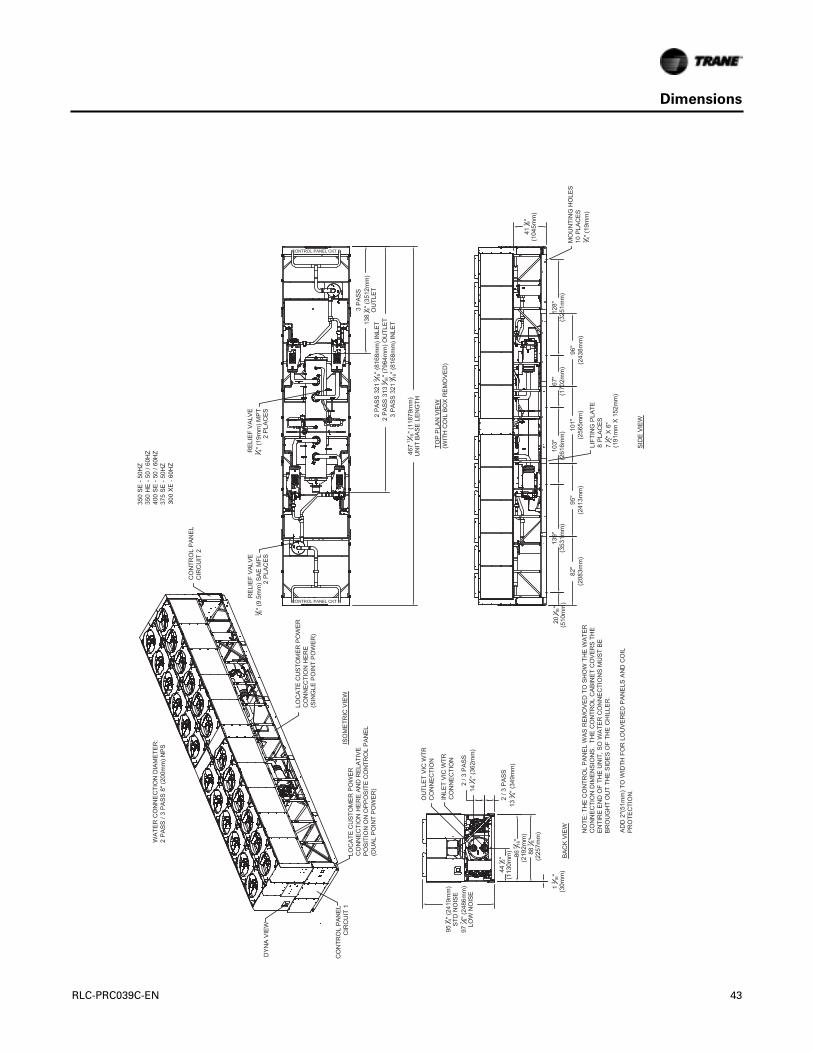
Dimensions
Note: Mounting location dimensions may vary on units with seismic rating. See unit submittals.
36 RLC-PRC039C-EN

Dimensions
RLC-PRC039C-EN 37
Dimensions
140 X
E -
60
HZ
5/8
38 RLC-PRC039C-EN

Dimensions
155,
170
XE
- 6
0 H
Z&
155
XE
,
RLC-PRC039C-EN 39
Dimensions
40 RLC-PRC039C-EN
Dimensions
250
XE
- 6
0 H
Z
ON
275
, 300
& 2
50
RLC-PRC039C-EN 41
Dimensions
275
XE
- 6
0 H
Z
42 RLC-PRC039C-EN
Dimensions
300
XE
- 6
0HZ
RLC-PRC039C-EN 43

Dimensions
350
XE
- 6
0 H
Z
44 RLC-PRC039C-EN
RLC-PRC039C-EN 45
Weights
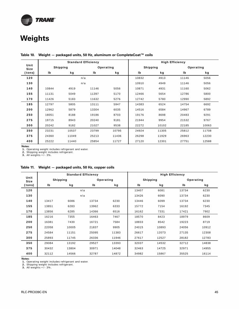
Table 10. Weight — packaged units, 50 Hz, aluminum or CompleteCoat™ coils
Unit Size
(tons)
Standard Efficiency High Efficiency
Shipping Operating Shipping Operating
lb kg lb kg lb kg lb kg
120 n/a 10832 4913 11146 5056
130 n/a 10910 4949 11146 5056
140 10844 4919 11146 5056 10871 4931 11160 5062
155 11131 5049 11397 5170 12466 5654 12786 5800
170 11426 5183 11632 5276 12742 5780 12990 5892
185 12797 5805 13111 5947 14383 6524 14754 6692
200 12962 5879 13304 6035 14516 6584 14967 6789
250 18051 8188 19186 8703 19176 8698 20483 9291
275 19715 8943 20240 9181 21944 9954 21532 9767
300 20242 9182 21027 9538 22272 10102 22185 10063
350 23231 10537 23799 10795 24924 11305 25812 11708
375 24360 11049 25213 11436 26298 11929 26963 12230
400 25222 11440 25854 11727 27120 12301 27751 12588
Notes:
1. Operating weight includes refrigerant and water. 2. Shipping weight includes refrigerant. 3. All weights +/- 3%.
Table 11. Weight — packaged units, 50 Hz, copper coils
Unit Size
(tons)
Standard Efficiency High Efficiency
Shipping Operating Shipping Operating
lb kg lb kg lb kg lb kg
120 n/a 13407 6081 13734 6230
130 n/a 13426 6090 13734 6230
140 13417 6086 13734 6230 13446 6099 13734 6230
155 13851 6283 13962 6333 15772 7154 16192 7345
170 13856 6285 14366 6516 16162 7331 17421 7902
185 16216 7355 16463 7467 18570 8423 18979 8609
200 16381 7430 16721 7584 18833 8542 19223 8719
250 22058 10005 21837 9905 24015 10893 24056 10912
275 24584 11151 25095 11383 26617 12073 27135 12308
300 25893 11745 26336 11946 27617 12527 28182 12783
350 29084 13192 29527 13393 32037 14532 32712 14838
375 30432 13804 30971 14048 32463 14725 32971 14955
400 32112 14566 32787 14872 34982 15867 35525 16114
Notes:
1. Operating weight includes refrigerant and water. 2. Shipping weight includes refrigerant. 3. All weights +/- 3%.

Mechanical Specifications
General
Units are leak and pressure tested at 390 psig high side, 250 psig low side, then evacuated andcharged. All air-cooled Series R® chillers are factory tested prior to shipment. Packaged units shipwith a full operating charge of oil and refrigerant. Unit panels, structural elements and controlboxes are constructed of galvanized steel and mounted on a welded structural steel base. Unitpanels and control boxes are finished with a baked on powder paint, and the structural base withan air dry paint. All paint meets the requirement for outdoor equipment of the US Navy and otherfederal government agencies.
Evaporator
The evaporator is a tube-in-shell heat exchanger design with internally and externally finnedcopper tubes roller expanded into the tube sheet.The evaporator is designed, tested and stampedin accordance with ASME for a refrigerant side working pressure of 200 psig.The evaporator isdesigned for a water side working pressure of 150 psig.Water connections are grooved pipe. Eachshell includes a vent, a drain and fittings for temperature control sensors and is insulated with3/4 inch equal insulation (K=0.28). Evaporator heaters with thermostat are provided to help protectthe evaporator from freezing at ambient temperatures down to -20°F (-29°C). Factory installed flowswitch is installed on a pipe stub in the evaporator inlet.
Condenser and Fans
Air-cooled condenser coils have aluminum fins mechanically bonded to internally finned seamlesscopper tubing.The condenser coil has an integral subcooling circuit. Condensers are factory proofand leak tested at 506 psig. Direct drive vertical discharge condenser fans are dynamicallybalanced.Totally enclosed air over motors completely seal the motor windings to preventexposure to ambient conditions.Three-phase condenser fan motors with permanently lubricatedball bearings and internal thermal overload protection are provided. Standard units will start andoperate between 25 to 115°F (-4 to 46°C) ambient.
Compressor and Lube Oil System
The rotary screw compressor is semi-hermetic, direct drive, 3000 rpm, 50 Hz, with capacity controlslide valve, a load/unload valve, rolling element bearings, differential refrigerant pressure oil pumpand oil heater.The motor is a suction gas cooled, hermetically sealed, two-pole squirrel cageinduction motor. Oil separator and filtration devices are provided separate from the compressor.Check valves in the compressor discharge and lube oil system and a solenoid valve in the lubesystem are also provided.
Refrigeration Circuits
Each unit has two refrigerant circuits, with one or two rotary screw compressors per circuit. Eachrefrigerant circuit includes a discharge service valve, liquid line shutoff valve, removable core filter,liquid line sight glass with moisture indicator, charging port, electronic expansion valve andoptional compressor suction service valve. Fully modulating compressors and electronicexpansion valves provide variable capacity modulation over the entire operating range.
Unit Controls
All unit controls are housed in an outdoor rated weather tight enclosure with removable plates toallow for customer connection of power wiring and remote interlocks. All controls, includingsensors, are factory mounted and tested prior to shipment. Microcomputer controls provide allcontrol functions including startup and shut down, leaving chilled water temperature control,evaporator flow proving, compressor and electronic expansion valve modulation, fan sequencing,anti-recycle logic, automatic lead/lag compressor starting and load limiting.The unit controlmodule, utilizing Adaptive Control™ microprocessor, automatically takes action to avoid unitshutdown due to abnormal operating conditions associated with low refrigerant pressure, highcondensing pressure and motor current overload. Should the abnormal operating conditioncontinue until a protective limit is violated, the unit will be shut down. Unit protective functions
46 RLC-PRC039C-EN

Mechanical Specifications
include loss of chilled water flow, evaporator freezing, loss of refrigerant, low refrigerant pressure,high refrigerant pressure, reverse rotation, compressor starting and running over current, phaseloss, phase imbalance, phase reversal, and loss of oil flow. A digital display indicates chilled watersetpoint and leaving chilled water temperature as standard. While current limit setpoint,evaporator and condenser refrigerant pressures, and electrical information are an option. Bothstandard and optional displays can be viewed on the unit without opening any control panel doors.Standard power connections include main three phase power to the compressors, condenser fansand control power transformer and optional connections are available for the 115 volt/60 Hz singlephase power for freeze protection on the evaporator heaters.
Starters
Starters are housed in a weather tight enclosure with removable cover plate to allow for customerconnection of power wiring.Across-the-line starters are standard on all 400/50 volt units.Wye Deltaclosed transition starters (33 percent of LRA inrush) are optional on 400/50 volt units.Typically,Trane helical rotary screw compressors are up to full speed in one second when started across-the-line and have equivalent inrush with similar size reciprocating compressor with part wind starters.
Chilled Water Reset
This provides the control logic and factory installed sensors to reset leaving chilled watertemperature.The setpoint can be reset based on ambient temperature or return evaporator watertemperature.
Flow Control
The factory installed flow switch is provided with the control logic and relays to turn the chilledwater flow on and off as the chiller requires for operation and protection.This function is arequirement on the air-cooled Series R® chiller.
RLC-PRC039C-EN 47

Options
Applications Options
High Efficiency/Performance Option
High efficiency option provides an increase in efficiency over standard efficiency by providingoversized heat exchangers for two purposes. One, it allows the unit to be more energy efficient.Two, the unit will have enhanced operation in high ambient conditions.
Ice Making
The ice making option provides special control logic and oil coolers to handle low temperaturebrine applications (less than 40°F [4.4°C] leaving evaporator temperature) for thermal storageapplications.
LowTemperature Brine
The low temperature option provides special control logic and oil coolers to handle lowtemperature brine applications (less than 40°F [4.4°C] leaving evaporator temperature).
Low Ambient Option
The low ambient option provides special control logic, oil coolers, and variable frequency driveson the condenser fan circuits to permit low temperature startup and operation down to 0°F (-18°C).
High Ambient Option
The high ambient option consists of special control logic and oil coolers to permit high ambient(up to 125°F [51°C]) operation.This option offers the best performance when coupled with the highefficiency performance option.
Electrical Options
Circuit Breaker
A HACR rated molded case capacity circuit breaker (UL approved) is available.The circuit breakercan also be used to disconnect the chiller from main power with a through the door handle andcomes pre-wired from the factory with terminal block power connections.The external operatorhandle is lockable.
Non-Fused Power Disconnect Switch
The non-fused molded case disconnect switch (UL approved) is used to disconnect the chiller frommain power and comes pre-wired from the factory with terminal block power connections.Theexternal operator handle is lockable.
Single/Dual Incoming Power Line Connection
Single or dual points of termination are available for incoming power line connections*. Units with3-4 compressors must order circuit breakers with the single point connection option.*Somerestrictions may apply.
Wye-Delta Compressor StartType
This option provides a reduced inrush starter. Wye-Delta starters are standard on 200-230 voltmachines.
Control Options
BACnet® Communications Interface
Allows the user to easily interface with BACnet® via a single twisted pair wiring to a factoryinstalled and tested communication board.
48 RLC-PRC039C-EN
Options
LonTalk® (LCI-C) Communications Interface
Provides the LONMARK® chiller profile inputs/outputs for use with a generic building automationsystem.
Remote Input Options
Permits remote chilled liquid setpoint, remote current limit setpoint, or both by accepting a 4-20mA or 2-10 Vdc analog signal.
Remote Output Options
Permits alarm relay outputs, ice making outputs, or both.
Tracer® Summit Communication Interface
Permits bi-directional communication to theTracer Summit system.
Other Options
Architectural Louvered Panels
Louvered panels cover the complete condensing coil and service area beneath the condenser.
Coil Protection
Louvered panels protect the condenser coils only.
Compressor Sound Enhancement
Factory installed weatherproof compressor enclosure to reduce compressor sound levels.
Condenser Corrosion Protection
Copper fins and CompleteCoat™ are available on all size units for corrosion protection. Job siteconditions should be matched with the appropriate condenser fin materials to inhibit coil corrosionand ensure extended equipment life.The CompleteCoat™ option provides fully assembled coilswith a flexible dip and bake epoxy coating.
Flange Kit
Provides a raised face flange kit that converts the grooved pipe evaporator water connections toflange connectors.
Insulation for High Humidity
The evaporator is covered with factory-installed 1.25 inch (31.8 mm) Armaflex II or equal (k=0.28)insulation. Foam insulation is used on the suction line.
Low Noise Fans
Complete fan assembly combining ultra quiet nine blade fans andTEAO fan motors to providesound reductions with no performance degradation to the unit.The fan blades are heavy-dutymolded plastic with wavy edges to reduce airflow turbulation.
Isolators - Neoprene
Isolators provide isolation between chiller and structure to help eliminate vibration transmission.Neoprene isolators are more effective and recommended over spring isolators.
Elastomeric Isolation Pads - Seismically Rated
Elastomeric isolation pads are designed and tested to control the motion of the chiller during aseismic event.
Isolators - Seismically Rated
Spring isolators are designed and tested to control the motion of the chiller during a seismic event.
RLC-PRC039C-EN 49

Options
Seismically Rated Unit - IBC & OSHPD
Unit is built and certified for seismic applications in accordance with OSHPD and the followingInternational Building Code (IBC) releases: 2000, 2003, 2006 and 2009.
PerformanceTests
Performance and witness tests are available, based on requested operating points, to certify chillerperformance in accordance with AHRI Standard 550/590.
Rapid Restart™Test
After completion of a standard full load witness test, power to the chiller will be cut and thenreapplied to demonstrate the chiller’s rapid restart capabilities for disaster relief.
Tarp
The unit will be covered at the factory with a PVC coated polyester tarp that is tied to the chiller baseto help protect the chiller from debris during shipment especially in the winter months and onshipping vessels.This option may also be helpful if the chiller will be stored at the jobsite beforeuse.
50 RLC-PRC039C-EN


We are committed to using environmentally
conscious print practices that reduce waste.
Ingersoll Rand (NYSE:IR) advances the quality of life by creating comfortable, sustainable and efficient environments.Our people and our family of brands—including Club Car®, Ingersoll Rand®,Thermo King® andTrane®—work togetherto enhance the quality and comfort of air in homes and buildings; transport and protect food and perishables; andincrease industrial productivity and efficiency. We are global business committed to a world of sustainable progress andenduring results. For more information, visit www.ingersollrand.com.
Ingersoll Rand has a policy of continuous product and product data improvement and reserves the right to change design and specifications without notice.
The AHRI Certified mark indicates Ingersoll Rand’s participation in the AHRI Certification program. For verification of individual certified products, go to
www.ahridirectory.org.
© 2016 Ingersoll Rand All rights reserved
RLC-PRC039C-EN 31 Oct 2016
Supersedes RLC-PRC039B-EN (15 Jan 2015)