Embed Size (px)
Citation preview
Printed in SpainTCGB0074 rev.0 - 04/2011
HITACHI participates in the Eurovent Certification Programme; thecertified data of certified models are listed in the Eurovent CertificationOnline Directory (www.eurovent-certification.com).
Hitachi Air Conditioning Products Europe, S.A. is certified with:ISO 9001 of AENOR, Spain for its Quality Management accordancewith the standardISO 14001 of AENOR Spain for its Environmental Managementsystems accordance with the standard.
Hitachi certifies that our products have met EU consumer safety,health and environmental requirements.
Hitachi Air Conditioning Products Europe, S.A.Ronda Shimizu, 1 - Políg. Ind. Can Torrella08233 Vacarisses (Barcelona) España
TCG
B00
74 re
v.0
- 04/
2011
RCU2E(40-400)AG2RHU2E(40-240)AG2
Technical Catalogue
SAMURAI SERIESAIR COOLED AND AIR TO WATER HEAT PUMPWATER CHILLERS-SCREW TYPE-
SA
MU
RA
I SE
RIE
S A
IR C
OO
LED
AN
D A
IR T
O W
AT
ER
HE
AT
PU
MP
WA
TE
R C
HIL
LER
S -
SC
RE
W T
YP
E-


Specifications in this manual are subject to change without notice in order that HITACHI may bring the latest innovations to their customers.
Whilst every effort is made to ensure that all specifications are correct, printing errors are beyond Hitachi’s control; Hitachi cannot be held responsible for these errors.
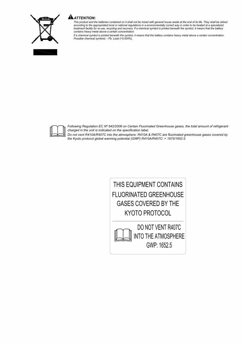
ATTENTION:This product and the batteries contained on it shall not be mixed with general house waste at the end of its life. They shall be retired according to the appropriated local or national regulations in a environmentally correct way in order to be treated at a specialized treatment facility for re-use, recycling and recovery. If a chemical symbol is printed beneath the symbol, it means that the battery contains heavy metal above a certain concentration. If a chemical symbol is printed beneath the symbol, it means that the battery contains heavy metal above a certain concentration. Possible chemical symbols: - Pb: Lead (>0,004%).
Following Regulation EC Nº 842/2006 on Certain Fluorinated Greenhouse gases, the total amount of refrigerant charged in the unit is indicated on the specification label.Do not vent R410A/R407C into the atmosphere: R410A & R407C are fluorinated greenhouse gases covered by the Kyoto protocol global warming potential (GWP) R410A/R407C: = 1975/1652.5.
Contents
Technical Catalogue
5TCGB0074 rev.0 04-2011
Important Notice
Features and Benefits
Operation Instructions
Components of chiller
Preparation Initial Check
Installation
Test Running
Controller Adjustment
Self-Inspection Functions
Control System
Maintenance
Troubleshooting
General Specifications
Drawings
Model Selection
Application Data
Components Data
1234567891011121314151617

7
Contents
TCGB0074 rev.0 04-2011
Technical Catalogue
Contents1. Important notice .......................................................................................112. Features and benefits ..............................................................................13
2.1. Unit picture ................................................................................................................14
2.2. Compressor ...............................................................................................................14
2.3. Control .......................................................................................................................16
2.4. Fan motor ..................................................................................................................17
2.5. Electronic expansion valve ........................................................................................18
3. Operation instructions..............................................................................193.1. Hitachi water chillers ..................................................................................................20
4. Components of chiller ..............................................................................214.1. Structure drawing ......................................................................................................22
5. Preparation initial check ..........................................................................255.1. Initial check ................................................................................................................26
5.2. Placing the unit ..........................................................................................................27
5.3. Gravity centre ............................................................................................................28
5.4. Service space and foundation ...................................................................................30
5.5. Transportation ............................................................................................................33
6. Installation ...............................................................................................356.1. Electrical Wiring .........................................................................................................36
6.2. Water Piping ..............................................................................................................38
6.3. Typical Common Water Piping ..................................................................................39
6.4. Minimum internal system water volume ....................................................................40
6.5. Water Control .............................................................................................................41
6.6. BMS gateways ...........................................................................................................42
6.7. Remote controllers ....................................................................................................49
6.8. Installation final check ..............................................................................................54
7. Test running .............................................................................................557.1. Preparation ................................................................................................................56
7.2. Test running ...............................................................................................................56
7.3. Instructions after test running ....................................................................................56
8. Controller adjustment ..............................................................................578.1. Control System ..........................................................................................................59
8.2. Controller Adjustment ................................................................................................60
9. Self-Inspection functions .........................................................................679.1. Alarm Indication .........................................................................................................68
9.2. Normal Indication .......................................................................................................69
9.3. Function for indication of operation condition ............................................................70
10. Control System ......................................................................................7710.1. Standard operation sequence R(C/H)U2E40AG2, 50AG2, 60AG2, 70AG2, 80AG2 78
10.2. Standard operation sequence R(C/H)U2E100AG2, 120AG2, 140AG2, 160AG2 ...79
10.3.Standard operation sequence R(C/H)U2E180AG2, 210AG2, 240AG2 ....................80
10.4. Standard Operation Sequence RCU2E280AG2, 320AG2 ......................................81
10.5. Standard Operation Sequence RCU2E350AG2, 400AG2 ......................................83
11. Maintenance ..........................................................................................8511.1. Components.............................................................................................................86
11.2. Lubrication ...............................................................................................................86
11.3. Deposit .....................................................................................................................86
11.4. Cleaning Method ......................................................................................................87
11.5. Winter Shutdown......................................................................................................89
11.6. Spring Start-Up ........................................................................................................89
11.7. Part Replacement ....................................................................................................89
11.8. Refrigeration Cycle ..................................................................................................89
11.9. Refrigerant cycle diagram of Hitachi Air-Cooled Water Chiller (RCU2E40, 50, 60, 70, 100, 120, 140, 180, 210, 280, 350AG2) ...........................90
11.10. Refrigerant cycle diagram of Hitachi Air-Cooled Water Chiller (RCU2E80, 160, 240, 320, 400AG2) with economiser. ..........................................91
11.11. Refrigerant cycle diagram of Hitachi Air-to-Water Heat Pump Water Chiller (RHU2E40, 50, 60, 70, 100, 120, 140, 180, 210AG2) ...........................................92
11.12. Refrigerant cycle diagram of Hitachi Air-to-Water Heat Pump Water Chiller (RHU2E80, 160, 240AG2) with economiser. ..........................................................93
11.13. Compressor Removal ............................................................................................94
11.14. Safety and protection control .................................................................................95
11.15. Normal operating pressure ....................................................................................96
11.16. Test Running And Maintenance Record .................................................................98
11.17. Daily Operating Records ........................................................................................99
11.18. Servicing for R407C Refrigerant System .............................................................100
12. Troubleshooting ...................................................................................10112.1.Procedures for trouble ............................................................................................102
13. General specifications .........................................................................10513.1. General Data .........................................................................................................106
13.2. Options line up .......................................................................................................113
14. Drawings..............................................................................................11514.1. Dimensional Drawing .............................................................................................116
14.2. Wiring Diagram ......................................................................................................124
15. Model Selection ...................................................................................14115.1. Selection Example .................................................................................................142
15.2. Performance Table (RCU2E-AG2).........................................................................143
15.3. Performance Table (RHU2E-AG2) (Cooling Operation) ........................................147
15.4. Performance Table (RHU2E-AG2) (Heating Operation) ........................................150
15.5. Electrical Data ......................................................................................................153
15.6. Sound Data ............................................................................................................155
16. Application Data...................................................................................15716.1. Working Range ......................................................................................................158
16.2. Part Load Performance .........................................................................................159
16.3. Ethylene Glycol Application ...................................................................................160
17. Components Data................................................................................16317.1. Compressor ...........................................................................................................164
17.2. Air Heat Exchanger and fan ...................................................................................164
17.3. Water Heat Exchanger ..........................................................................................165
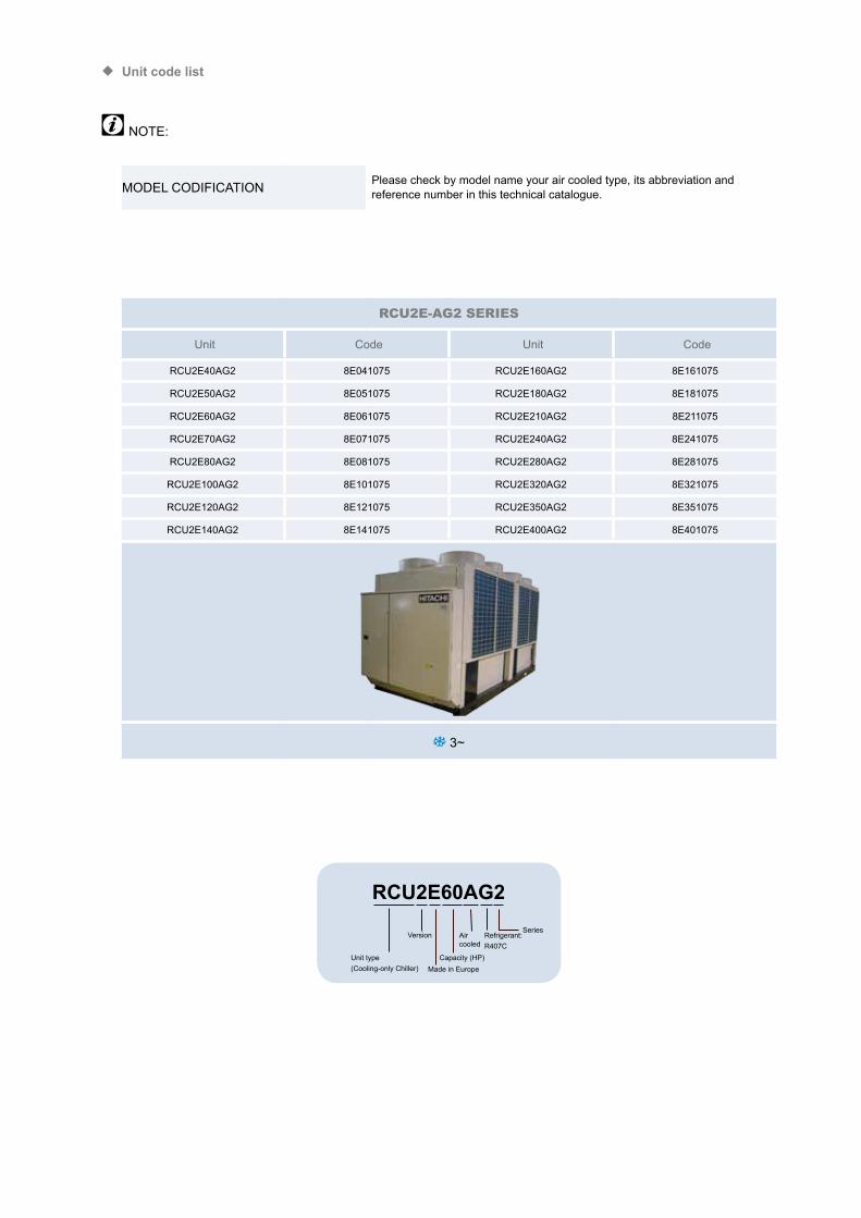
¡ Unit code list
NOTE:
MODEL CODIFICATION Please check by model name your air cooled type, its abbreviation and reference number in this technical catalogue.
RCU2E-AG2 SERIES
Unit Code Unit Code
RCU2E40AG2 8E041075 RCU2E160AG2 8E161075
RCU2E50AG2 8E051075 RCU2E180AG2 8E181075
RCU2E60AG2 8E061075 RCU2E210AG2 8E211075
RCU2E70AG2 8E071075 RCU2E240AG2 8E241075
RCU2E80AG2 8E081075 RCU2E280AG2 8E281075
RCU2E100AG2 8E101075 RCU2E320AG2 8E321075
RCU2E120AG2 8E121075 RCU2E350AG2 8E351075
RCU2E140AG2 8E141075 RCU2E400AG2 8E401075
3~
RCU2E60AG2
Unit type(Cooling-only Chiller)
VersionSeries
Air cooled
Made in EuropeCapacity (HP)
Refrigerant:R407C
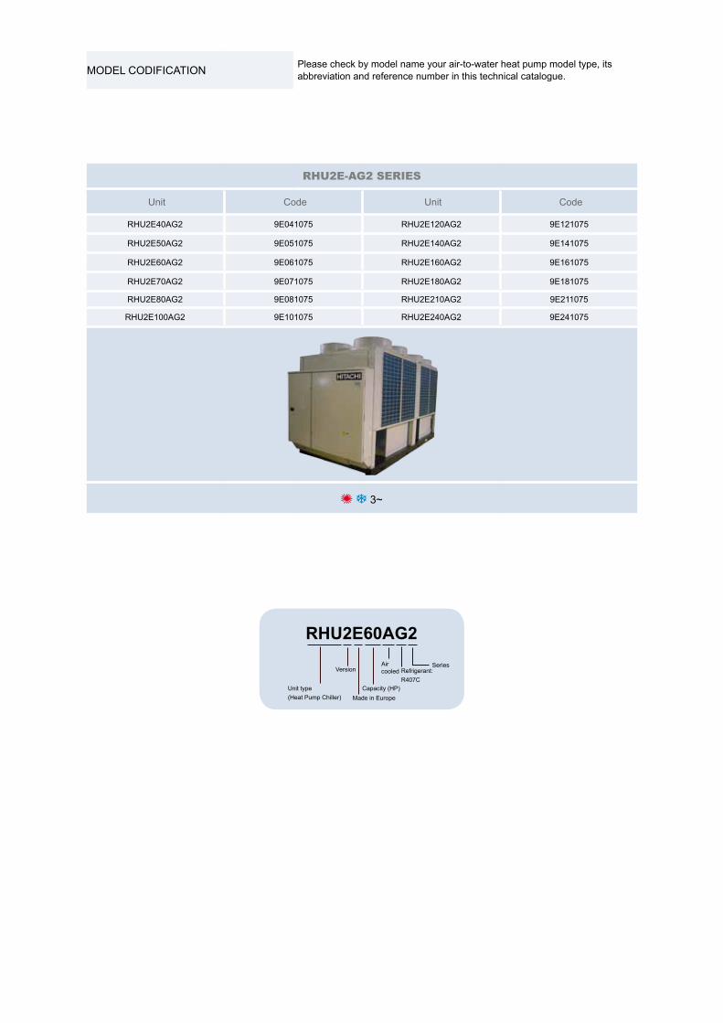
MODEL CODIFICATION Please check by model name your air-to-water heat pump model type, its abbreviation and reference number in this technical catalogue.
RHU2E-AG2 SERIES
Unit Code Unit Code
RHU2E40AG2 9E041075 RHU2E120AG2 9E121075
RHU2E50AG2 9E051075 RHU2E140AG2 9E141075
RHU2E60AG2 9E061075 RHU2E160AG2 9E161075
RHU2E70AG2 9E071075 RHU2E180AG2 9E181075
RHU2E80AG2 9E081075 RHU2E210AG2 9E211075
RHU2E100AG2 9E101075 RHU2E240AG2 9E241075
3~
RHU2E60AG2
Unit type(Heat Pump Chiller)
VersionSeriesAir
cooled
Made in EuropeCapacity (HP)
Refrigerant:R407C
Important Notice
Technical Catalogue
11. I m p o r t a n t N o t i c e
11TCGB0074 rev.0 04-2011
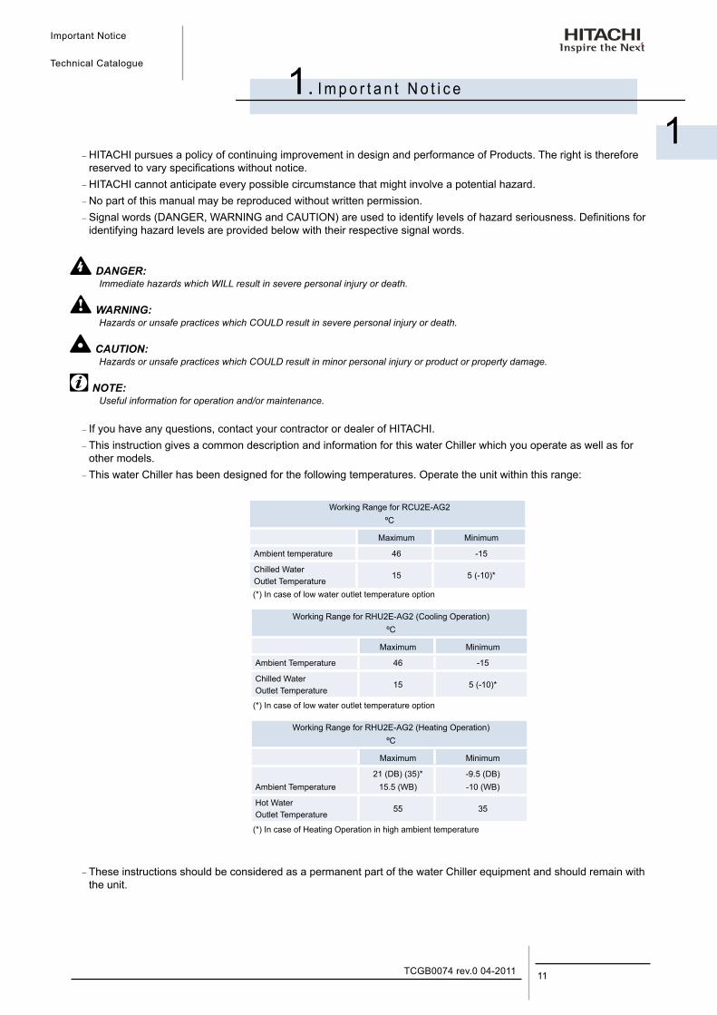
− HITACHI pursues a policy of continuing improvement in design and performance of Products. The right is therefore reserved to vary specifications without notice. − HITACHI cannot anticipate every possible circumstance that might involve a potential hazard. − No part of this manual may be reproduced without written permission. − Signal words (DANGER, WARNING and CAUTION) are used to identify levels of hazard seriousness. Definitions for identifying hazard levels are provided below with their respective signal words.
DANGER:Immediate hazards which WILL result in severe personal injury or death.
WARNING:Hazards or unsafe practices which COULD result in severe personal injury or death.
CAUTION:Hazards or unsafe practices which COULD result in minor personal injury or product or property damage.
NOTE:Useful information for operation and/or maintenance.
− If you have any questions, contact your contractor or dealer of HITACHI. − This instruction gives a common description and information for this water Chiller which you operate as well as for other models. − This water Chiller has been designed for the following temperatures. Operate the unit within this range:
Working Range for RCU2E-AG2ºC
Maximum Minimum
Ambient temperature 46 -15
Chilled WaterOutlet Temperature
15 5 (-10)*
(*) In case of low water outlet temperature option
Working Range for RHU2E-AG2 (Cooling Operation)ºC
Maximum Minimum
Ambient Temperature 46 -15
Chilled WaterOutlet Temperature
15 5 (-10)*
(*) In case of low water outlet temperature option
Working Range for RHU2E-AG2 (Heating Operation)ºC
Maximum Minimum
Ambient Temperature21 (DB) (35)*
15.5 (WB)-9.5 (DB)-10 (WB)
Hot WaterOutlet Temperature
55 35
(*) In case of Heating Operation in high ambient temperature
− These instructions should be considered as a permanent part of the water Chiller equipment and should remain with the unit.

Features and Benefits
Technical Catalogue
2
2. F e a t u r e s a n d B e n e f i t s
13TCGB0074 rev.0 04-2011
Contents
2. Features and benefits ..................................................................................................132.1. Unit picture .............................................................................................................................................. 14
2.2. Compressor ............................................................................................................................................. 14
2.3. Control ..................................................................................................................................................... 16
2.4. Fan motor ................................................................................................................................................ 17
2.5. Electronic expansion valve ...................................................................................................................... 18
Features and Benefits
Technical Catalogue
TCGB0074 rev.0 04-201114
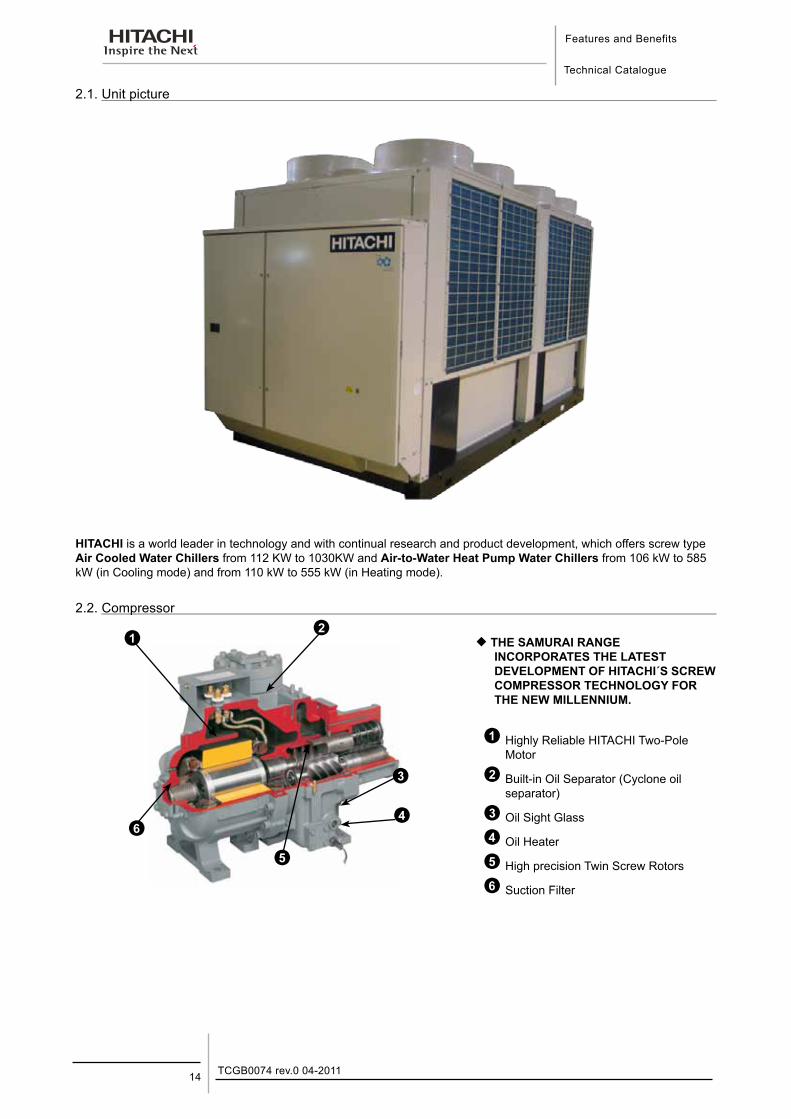
2.1. Unit picture
HITACHI is a world leader in technology and with continual research and product development, which offers screw type Air Cooled Water Chillers from 112 KW to 1030KW and Air-to-Water Heat Pump Water Chillers from 106 kW to 585 kW (in Cooling mode) and from 110 kW to 555 kW (in Heating mode).
2.2. Compressor
¡ THE SAMURAI RANGE INCORPORATES THE LATEST DEVELOPMENT OF HITACHI´S SCREW COMPRESSOR TECHNOLOGY FOR THE NEW MILLENNIUM.
Highly Reliable HITACHI Two-Pole Motor
Built-in Oil Separator (Cyclone oil separator)
Oil Sight Glass
Oil Heater
High precision Twin Screw Rotors
Suction Filter
Features and Benefits
Technical Catalogue
2
15TCGB0074 rev.0 04-2011
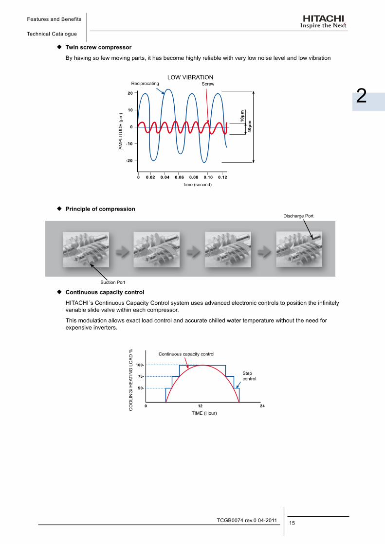
¡ Twin screw compressor
By having so few moving parts, it has become highly reliable with very low noise level and low vibration
LOW VIBRATION
¡ Principle of compression
¡ Continuous capacity control
HITACHI´s Continuous Capacity Control system uses advanced electronic controls to position the infinitely variable slide valve within each compressor.
This modulation allows exact load control and accurate chilled water temperature without the need for expensive inverters.
CO
OLI
NG
/ HE
ATIN
G L
OA
D % Continuous capacity control
Step control
TIME (Hour)
Reciprocating Screw
AM
PLI
TUD
E (µ
m)
Time (second)
Suction Port
Discharge Port
Features and Benefits
Technical Catalogue
TCGB0074 rev.0 04-201116
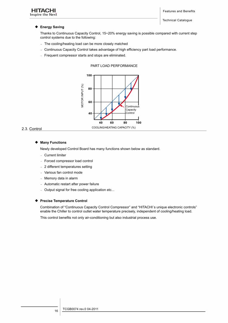
¡ Energy Saving
Thanks to Continuous Capacity Control, 15~20% energy saving is possible compared with current step control systems due to the following:
− The cooling/heating load can be more closely matched
− Continuous Capacity Control takes advantage of high efficiency part load performance.
− Frequent compressor starts and stops are eliminated.
PART LOAD PERFORMANCE
2.3. Control
¡ Many Functions
Newly developed Control Board has many functions shown below as standard.
− Current limiter
− Forced compressor load control
− 2 different temperatures setting
− Various fan control mode
− Memory data in alarm
− Automatic restart after power failure
− Output signal for free cooling application etc...
¡ Precise Temperature Control
Combination of “Continuous Capacity Control Compressor” and “HITACHI´s unique electronic controls” enable the Chiller to control outlet water temperature precisely, independent of cooling/heating load.
This control benefits not only air-conditioning but also industrial process use.
MO
TOR
INP
UT
(%)
Continuous Capacity Control
COOLING/HEATING CAPACITY (%)
Features and Benefits
Technical Catalogue
2
17TCGB0074 rev.0 04-2011
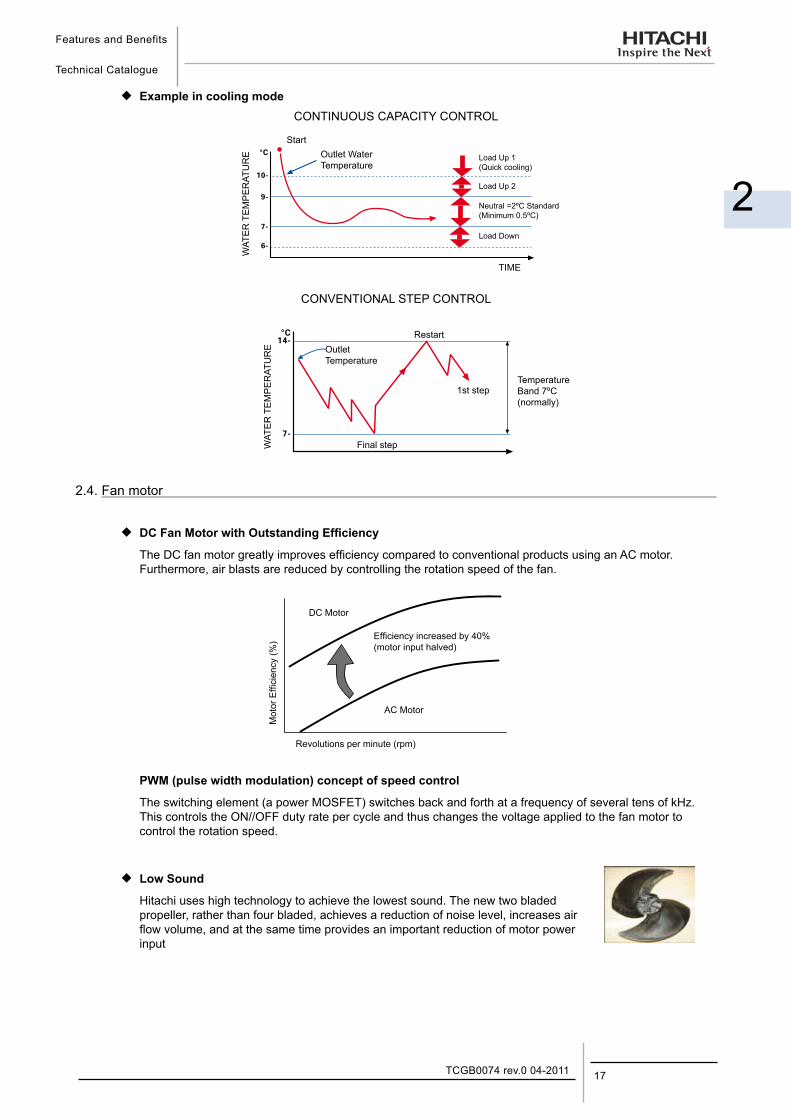
¡ Example in cooling modeCONTINUOUS CAPACITY CONTROL
CONVENTIONAL STEP CONTROL
2.4. Fan motor
¡ DC Fan Motor with Outstanding Efficiency
The DC fan motor greatly improves efficiency compared to conventional products using an AC motor. Furthermore, air blasts are reduced by controlling the rotation speed of the fan.
PWM (pulse width modulation) concept of speed control
The switching element (a power MOSFET) switches back and forth at a frequency of several tens of kHz. This controls the ON//OFF duty rate per cycle and thus changes the voltage applied to the fan motor to control the rotation speed.
¡ Low Sound
Hitachi uses high technology to achieve the lowest sound. The new two bladed propeller, rather than four bladed, achieves a reduction of noise level, increases air flow volume, and at the same time provides an important reduction of motor power input
Mot
or E
ffici
ency
(%)
DC Motor
Efficiency increased by 40% (motor input halved)
AC Motor
Revolutions per minute (rpm)
TIME
Load Down
Neutral =2ºC Standard (Minimum 0.5ºC)
Load Up 2
Load Up 1 (Quick cooling)
Outlet Water Temperature
WAT
ER
TE
MP
ER
ATU
RE
Start
WAT
ER
TE
MP
ER
ATU
RE
RestartOutlet Temperature
1st step
Final step
Temperature Band 7ºC (normally)
Features and Benefits
Technical Catalogue
TCGB0074 rev.0 04-201118
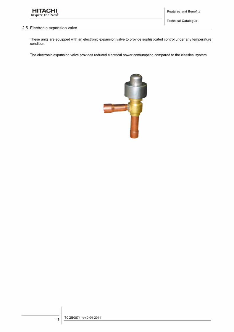
2.5. Electronic expansion valve
These units are equipped with an electronic expansion valve to provide sophisticated control under any temperature condition.
The electronic expansion valve provides reduced electrical power consumption compared to the classical system.
Operation Instructions
Technical Catalogue
3
3. O p e r a t i o n I n s t r u c t i o n s
19TCGB0074 rev.0 04-2011
Contents
3. Operation instructions..................................................................................................193.1. Hitachi water chillers................................................................................................................................ 20
Operation Instructions
Technical Catalogue
TCGB0074 rev.0 04-201120
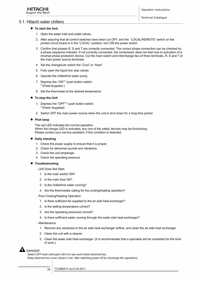
3.1. Hitachi water chillers ¡ To start the Unit.
1. Open the water inlet and outlet valves.
2. After assuring that all control switches have been cut OFF, and the “LOCAL/REMOTE” switch on the printed circuit board is in the “LOCAL” position, turn ON the power switch.
3. Confirm that phases R, S and T are correctly connected. The correct phase connection can be checked by a phase sequence indicator. If not correctly connected, the compressor does not start due to activation of a reversal phase protection device. Cut the main switch and interchange two of three terminals, R, S and T at the main power source terminals.
4. Set the changeover switch the “Cool” or “Heat”
5. Fully open the liquid line stop valves.
6. Operate the chilled/hot water pump.
7. Depress the “ON”(*) push button switch. (*)(Field-Supplied )
8. Set the thermostat at the desired temperature
¡ To stop the Unit
1. Depress the “OFF”(*) push button switch.(*)(Field–Supplied)
2. Switch OFF the main power source when the unit is shut down for a long time period.
¡ Pilot lamp
The red LED indicates the normal operation. When the orange LED is activated, any one of the safety devices may be functioning. Please contact your service assistant, if this condition is detected.
¡ Daily checking1. Check the power supply to ensure that it is proper.2. Check for abnormal sounds and vibrations.3. Check the unit amperage.4. Check the operating pressure.
¡ Troubleshooting
− Unit Does Not Start
1. Is the main switch ON?
2. Is the main fuse OK?
3. Is the chilled/hot water running?
4. Are the thermostats calling for the cooling/heating operation?
− Poor Cooling/Heating Operation
1. Is there sufficient Air supplied to the air side heat exchanger?
2. Is the setting temperature correct?
3. Are the operating pressures normal?
4. Is there sufficient water running through the water side heat exchanger?
− Maintenance
1. Remove any obstacles to the air side heat exchanger airflow, and clean the air side heat exchanger.
2. Clean the unit with a cleaner.
3. Clean the water side heat exchanger. (It is recommended that a specialist will be contacted for this kind of work.)
DANGER:Switch OFF main interruptor (M.I) for any work inside electrical box.Keep electrical box cover closed 2 min. after switching power off (to discharge the capacitors).
Components of ChillerTechnical Catalogue
4
4. C o m p o n e n t s o f C h i l l e r
21TCGB0074 rev.0 04-2011
Contents
4. Components of chiller ..................................................................................................214.1. Structure drawing .................................................................................................................................... 22
Components of Chiller
Technical Catalogue
TCGB0074 rev.0 04-201122
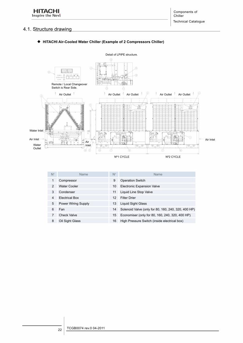
4.1. Structure drawing
¡ HITACHI Air-Cooled Water Chiller (Example of 2 Compressors Chiller)
N° Name N° Name
1 Compressor 9 Operation Switch
2 Water Cooler 10 Electronic Expansion Valve
3 Condenser 11 Liquid Line Stop Valve
4 Electrical Box 12 Filter Drier
5 Power Wiring Supply 13 Liquid Sight Glass
6 Fan 14 Solenoid Valve (only for 80, 160, 240, 320, 400 HP)
7 Check Valve 15 Economiser (only for 80, 160, 240, 320, 400 HP)
8 Oil Sight Glass 16 High Pressure Switch (inside electrical box)
Detail of LPIPE structure.
Remote / Local Changeover Switch is Rear Side.
Air Outlet Air Outlet Air Outlet Air Outlet Air Outlet
Water Inlet
Air Inlet
Air InletAir Inlet
Water Outlet
Nº1 CYCLE Nº2 CYCLE
Components of ChillerTechnical Catalogue
4
23TCGB0074 rev.0 04-2011
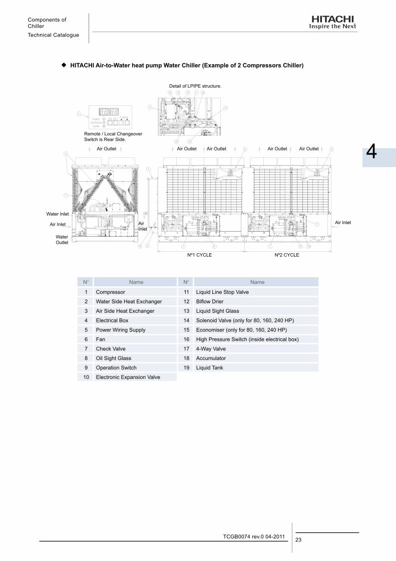
¡ HITACHI Air-to-Water heat pump Water Chiller (Example of 2 Compressors Chiller)
Detail of LPIPE structure.
Remote / Local Changeover Switch is Rear Side.
Air Outlet Air Outlet Air Outlet Air Outlet Air Outlet
Water Inlet
Air Inlet
Air InletAir Inlet
Water Outlet
Nº1 CYCLE Nº2 CYCLE
N° Name N° Name
1 Compressor 11 Liquid Line Stop Valve
2 Water Side Heat Exchanger 12 Biflow Drier
3 Air Side Heat Exchanger 13 Liquid Sight Glass
4 Electrical Box 14 Solenoid Valve (only for 80, 160, 240 HP)
5 Power Wiring Supply 15 Economiser (only for 80, 160, 240 HP)
6 Fan 16 High Pressure Switch (inside electrical box)
7 Check Valve 17 4-Way Valve
8 Oil Sight Glass 18 Accumulator
9 Operation Switch 19 Liquid Tank
10 Electronic Expansion Valve

Preparation initial checkTechnical Catalogue
5
5. P r e p a r a t i o n I n i t i a l C h e c k
25TCGB0074 rev.0 04-2011
Contents
5. Preparation initial check ..............................................................................................255.1. Initial check .............................................................................................................................................. 26
5.2. Placing the unit ........................................................................................................................................ 27
5.3. Gravity centre .......................................................................................................................................... 28
5.4. Service space and foundation ................................................................................................................. 30
5.5. Transportation.......................................................................................................................................... 33
5.5.1. Transportation by Rigging ............................................................................................................................... 335.5.2. Declining the unit during transportation. .......................................................................................................... 33
Preparation initial check
Technical Catalogue
TCGB0074 rev.0 04-201126
5.1. Initial check
¡ Required Materials
Measure and Architectural Information Regarding Installation Location
¡ Installation Location
Confirm that the final installation location is provided with convenient piping and wiring work. Strong water runoff should be avoided.
This unit must be installed in a restricted area not accessible to the general public. Install the unit on a roof or in an area where people, except service engineer, can not touch the unit.
¡ Installation Space
Check for obstacles which restrict condenser Air flow or hamper maintenance work in the space specified in Fig. 1.
¡ Foundation
Check to ensure that the foundation is flat, level and sufficiently strong, taking into account the maximum foundation gradient (Fig. 2) and the unit weight balance. Confirm elevation provision for the unit on a solid base with an iron frame or concrete curbs shown in chapter 5.4.
In order to obtain proper clearance beneath the unit for either rooftop or on the ground installation, where foundation bolts should be sunk into concrete. Additionally, for on the ground installation, provide a gravel or concrete space around the condenser Air intake in order to avoid airflow obstruction due to grass or other vegetation.
¡ Unit
Check to ensure that the unit has been transported without damage. File a damage claim with the transportation companies if mishandling due to transportation company negligence is suspected.
¡ Transportation
Secure the route to the final installation location by confirming the dimensions (Refer to the “General Data” in Chapter 13.1).
DANGER:If leakage is detected, stop the unit and contact the installer or service shop. Do not use a naked fire near the refrigerant gas. If a naked fire is utilised near the refrigerant gas, refrigerant is turned into a harmful phosgene compound.
WARNING:This unit is operated with refrigerant R407C, which is non-flammable and non-poisonous. However, refrigerant itself is heavier than the atmosphere so that a floor is covered with refrigerant gas if refrigerant is leaked. Therefore, keep good ventilation to avoid choke during servicing.
CAUTION:Check to ensure that valves are correctly opened. If not opened, serious damage will occur to the compressor due to an abnormal high pressure.This unit controls air flow for condenser during low ambient temperature.Due to this control, avoid the strong wind hits the unit directly. In such a case, put buffer plate around the unit.
Preparation initial checkTechnical Catalogue
5
27TCGB0074 rev.0 04-2011
5.2. Placing the unit
¡ Tools and Instruments
Pincers, Wrenches, Facilities to Transport and Place The Unit.
¡ Transportation
Transport the unit as close to the final installation location as practical before unpacking is accomplished. Provide adequate facilities to place the unit on the foundation, with sufficient consideration given to those individuals performing the installation.
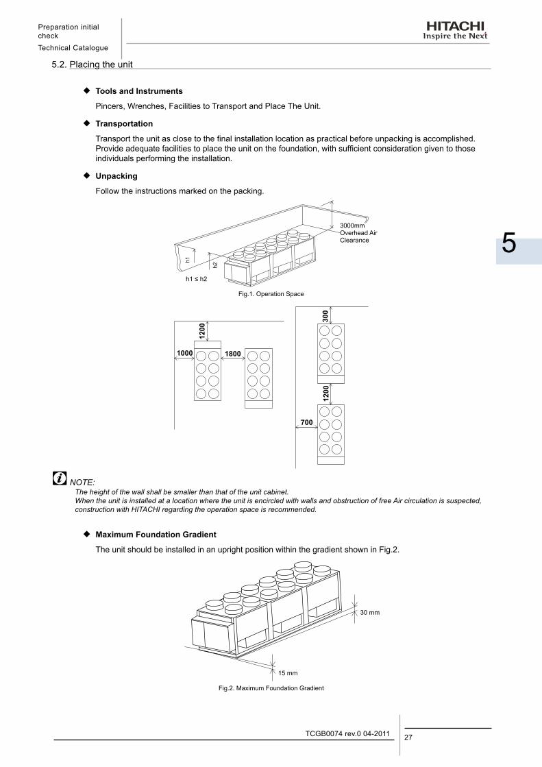
¡ Unpacking
Follow the instructions marked on the packing.
Fig.1. Operation Space
NOTE:The height of the wall shall be smaller than that of the unit cabinet. When the unit is installed at a location where the unit is encircled with walls and obstruction of free Air circulation is suspected, construction with HITACHI regarding the operation space is recommended.
¡ Maximum Foundation Gradient
The unit should be installed in an upright position within the gradient shown in Fig.2.
Fig.2. Maximum Foundation Gradient
15 mm
30 mm
3000mm Overhead Air Clearance
h1 ≤ h2
h1
h2
Preparation initial check
Technical Catalogue
TCGB0074 rev.0 04-201128
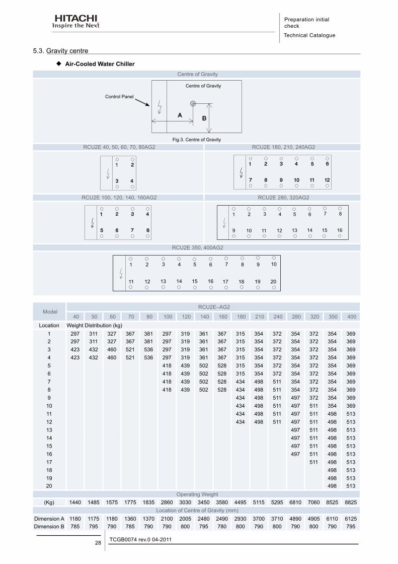
5.3. Gravity centre
¡ Air-Cooled Water ChillerCentre of Gravity
Fig.3. Centre of GravityRCU2E 40, 50, 60, 70, 80AG2 RCU2E 180, 210, 240AG2
RCU2E 100, 120, 140, 160AG2 RCU2E 280, 320AG2
RCU2E 350, 400AG2
ModelRCU2E–AG2
40 50 60 70 80 100 120 140 160 180 210 240 280 320 350 400Location Weight Distribution (kg)
1 297 311 327 367 381 297 319 361 367 315 354 372 354 372 354 3692 297 311 327 367 381 297 319 361 367 315 354 372 354 372 354 3693 423 432 460 521 536 297 319 361 367 315 354 372 354 372 354 3694 423 432 460 521 536 297 319 361 367 315 354 372 354 372 354 3695 418 439 502 528 315 354 372 354 372 354 3696 418 439 502 528 315 354 372 354 372 354 3697 418 439 502 528 434 498 511 354 372 354 3698 418 439 502 528 434 498 511 354 372 354 3699 434 498 511 497 372 354 36910 434 498 511 497 511 354 36911 434 498 511 497 511 498 51312 434 498 511 497 511 498 51313 497 511 498 51314 497 511 498 51315 497 511 498 51316 497 511 498 51317 511 498 51318 498 51319 498 51320 498 513
Operating Weight(Kg) 1440 1485 1575 1775 1835 2860 3030 3450 3580 4495 5115 5295 6810 7060 8525 8825
Location of Centre of Gravity (mm)Dimension A 1180 1175 1180 1360 1370 2100 2005 2480 2490 2930 3700 3710 4890 4905 6110 6125Dimension B 785 795 790 785 790 790 800 795 780 800 790 800 790 800 790 795
Centre of Gravity
Control Panel
Preparation initial checkTechnical Catalogue
5
29TCGB0074 rev.0 04-2011
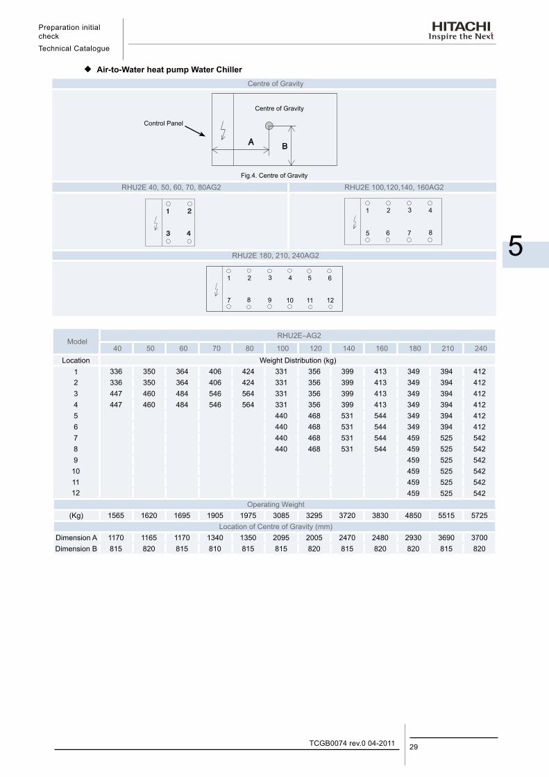
¡ Air-to-Water heat pump Water ChillerCentre of Gravity
Fig.4. Centre of Gravity
RHU2E 40, 50, 60, 70, 80AG2 RHU2E 100,120,140, 160AG2
RHU2E 180, 210, 240AG2
ModelRHU2E–AG2
40 50 60 70 80 100 120 140 160 180 210 240Location Weight Distribution (kg)
1 336 350 364 406 424 331 356 399 413 349 394 4122 336 350 364 406 424 331 356 399 413 349 394 4123 447 460 484 546 564 331 356 399 413 349 394 4124 447 460 484 546 564 331 356 399 413 349 394 4125 440 468 531 544 349 394 4126 440 468 531 544 349 394 4127 440 468 531 544 459 525 5428 440 468 531 544 459 525 5429 459 525 542
10 459 525 54211 459 525 54212 459 525 542
Operating Weight(Kg) 1565 1620 1695 1905 1975 3085 3295 3720 3830 4850 5515 5725
Location of Centre of Gravity (mm)Dimension A 1170 1165 1170 1340 1350 2095 2005 2470 2480 2930 3690 3700Dimension B 815 820 815 810 815 815 820 815 820 820 815 820
Centre of Gravity
Control Panel
Preparation initial check
Technical Catalogue
TCGB0074 rev.0 04-201130
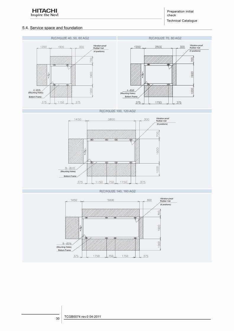
5.4. Service space and foundation
R(C/H)U2E 40, 50, 60 AG2 R(C/H)U2E 70, 80 AG2
Vibration-proof Rubber mat
(4 positions)
(Mounting Holes)
Bottom Frame
Vibration-proof Rubber mat(4 positions)
(Mounting Holes)
Bottom Frame
R(C/H)U2E 100, 120 AG2
Vibration-proof Rubber mat(8 positions)
(Mounting Holes)
Bottom Frame
R(C/H)U2E 140, 160 AG2
Vibration-proof Rubber mat
(8 positions)
(Mounting Holes)Bottom Frame
Preparation initial checkTechnical Catalogue
5
31TCGB0074 rev.0 04-2011
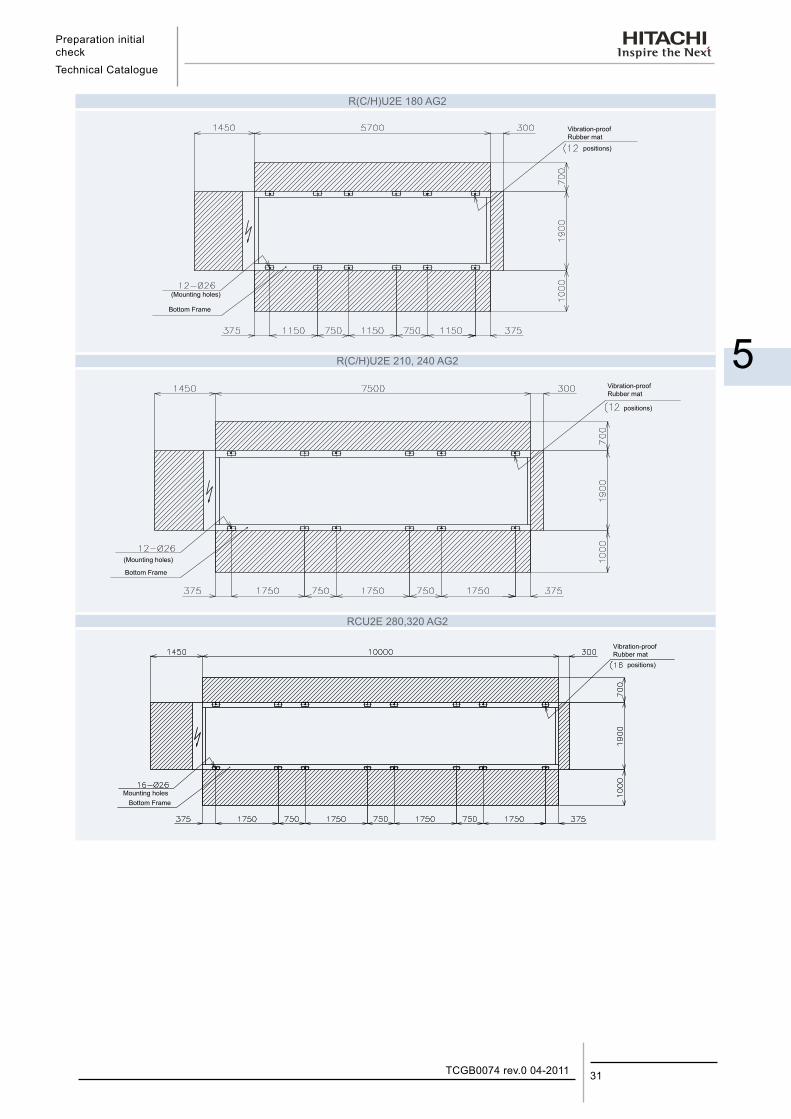
R(C/H)U2E 180 AG2
Vibration-proof Rubber mat
Bottom Frame
positions)
(Mounting holes)
R(C/H)U2E 210, 240 AG2
Bottom Frame
Vibration-proof Rubber mat
positions)
(Mounting holes)
RCU2E 280,320 AG2
Vibration-proof Rubber mat
Bottom Frame
positions)
Mounting holes
Preparation initial check
Technical Catalogue
TCGB0074 rev.0 04-201132
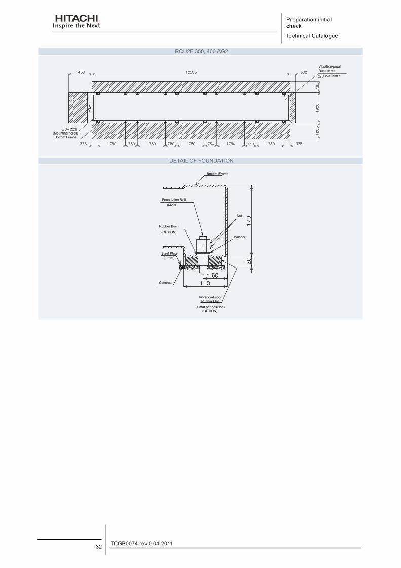
RCU2E 350, 400 AG2
Vibration-proof Rubber mat
Bottom Frame
positions)
(Mounting holes)
DETAIL OF FOUNDATION
Bottom Frame
Foundation Bolt
Rubber Bush
(OPTION)
Steel Plate
Concrete
Washer
Vibration-ProofRubber Mat
(1 mat per position)(OPTION)
Nut
(M20)
(1 mm)
Preparation initial checkTechnical Catalogue
5
33TCGB0074 rev.0 04-2011
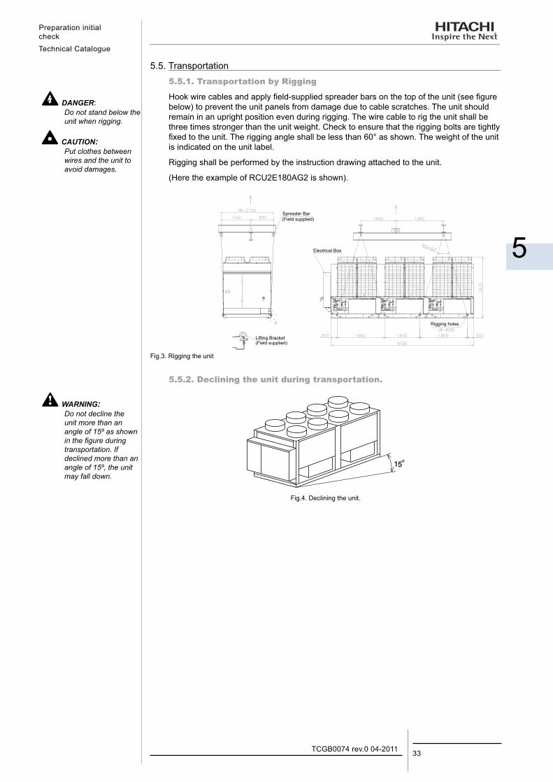
5.5. Transportation5.5.1. Transportation by Rigging
Hook wire cables and apply field-supplied spreader bars on the top of the unit (see figure below) to prevent the unit panels from damage due to cable scratches. The unit should remain in an upright position even during rigging. The wire cable to rig the unit shall be three times stronger than the unit weight. Check to ensure that the rigging bolts are tightly fixed to the unit. The rigging angle shall be less than 60° as shown. The weight of the unit is indicated on the unit label.
Rigging shall be performed by the instruction drawing attached to the unit.
(Here the example of RCU2E180AG2 is shown).
Fig.3. Rigging the unit
5.5.2. Declining the unit during transportation.
Fig.4. Declining the unit.
DANGER:Do not stand below the unit when rigging.
CAUTION:Put clothes between wires and the unit to avoid damages.
WARNING:Do not decline the unit more than an angle of 15º as shown in the figure during transportation. If declined more than an angle of 15º, the unit may fall down.
Spreader Bar
Lifting Bracket(Field supplied)
(Field supplied)
Electrical Box
Rigging holes

Installation
Technical Catalogue
6
6. I n s t a l l a t i o n
35TCGB0074 rev.0 04-2011
Contents
6. Installation ...................................................................................................................356.1. Electrical Wiring ....................................................................................................................................... 36
6.2. Water Piping ............................................................................................................................................ 38
6.3. Typical Common Water Piping ................................................................................................................ 39
6.4. Minimum internal system water volume .................................................................................................. 40
6.5. Water Control .......................................................................................................................................... 41
6.6. BMS gateways......................................................................................................................................... 426.6.1. HARDC70-CE1 (OP) - LonWorks® interface. .................................................................................................. 426.6.2 HC-A32MB - ModBus interface ........................................................................................................................ 46
6.7. Remote controllers .................................................................................................................................. 496.7.1. CSC-5S – Central Station ............................................................................................................................ 496.7.2. CSNET Web – Computer central control ..................................................................................................... 51
6.8. Installation final check ............................................................................................................................ 546.8.1. Installation Work Check List ............................................................................................................................ 54
Installation
Technical Catalogue
TCGB0074 rev.0 04-201136
6.1. Electrical Wiring ¡ Tools and Instruments
One Set of Wiring tools and Electrical Tester (Clamp Meter)
¡ Schedule Check
DANGER:Switch OFF main interruptor (M.I) for any work inside electrical box.Keep electrical box cover closed 2 min. after switching power off (to discharge the capacitors)
WARNING:
− Confirm that the field-selected electrical components (main power switch, fuses, wires, conduit connections, wire terminals and others) are properly selected according to the “Electrical Data“ in this Technical Catalogue, and ensure that they comply with national and local codes.
− It is recommended that the main power switch be locked in the “OFF“ position, to prevent against accidental supply of power during equipment servicing.
− Check to ensure that an earthing wire is correctly connected to the unit. This wire protects from an electric shock. Utilisation of an earth leakage breaker is necessary.
− Unit access must be restricted to the general public.
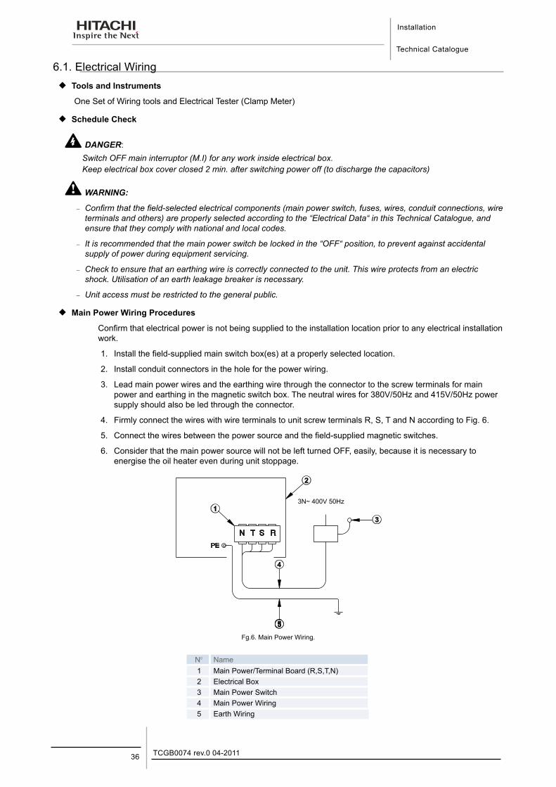
¡ Main Power Wiring Procedures
Confirm that electrical power is not being supplied to the installation location prior to any electrical installation work.
1. Install the field-supplied main switch box(es) at a properly selected location.
2. Install conduit connectors in the hole for the power wiring.
3. Lead main power wires and the earthing wire through the connector to the screw terminals for main power and earthing in the magnetic switch box. The neutral wires for 380V/50Hz and 415V/50Hz power supply should also be led through the connector.
4. Firmly connect the wires with wire terminals to unit screw terminals R, S, T and N according to Fig. 6.
5. Connect the wires between the power source and the field-supplied magnetic switches.
6. Consider that the main power source will not be left turned OFF, easily, because it is necessary to energise the oil heater even during unit stoppage.
Fg.6. Main Power Wiring.
N° Name1 Main Power/Terminal Board (R,S,T,N)2 Electrical Box3 Main Power Switch4 Main Power Wiring5 Earth Wiring
3N~ 400V 50Hz
Installation
Technical Catalogue
6
37TCGB0074 rev.0 04-2011
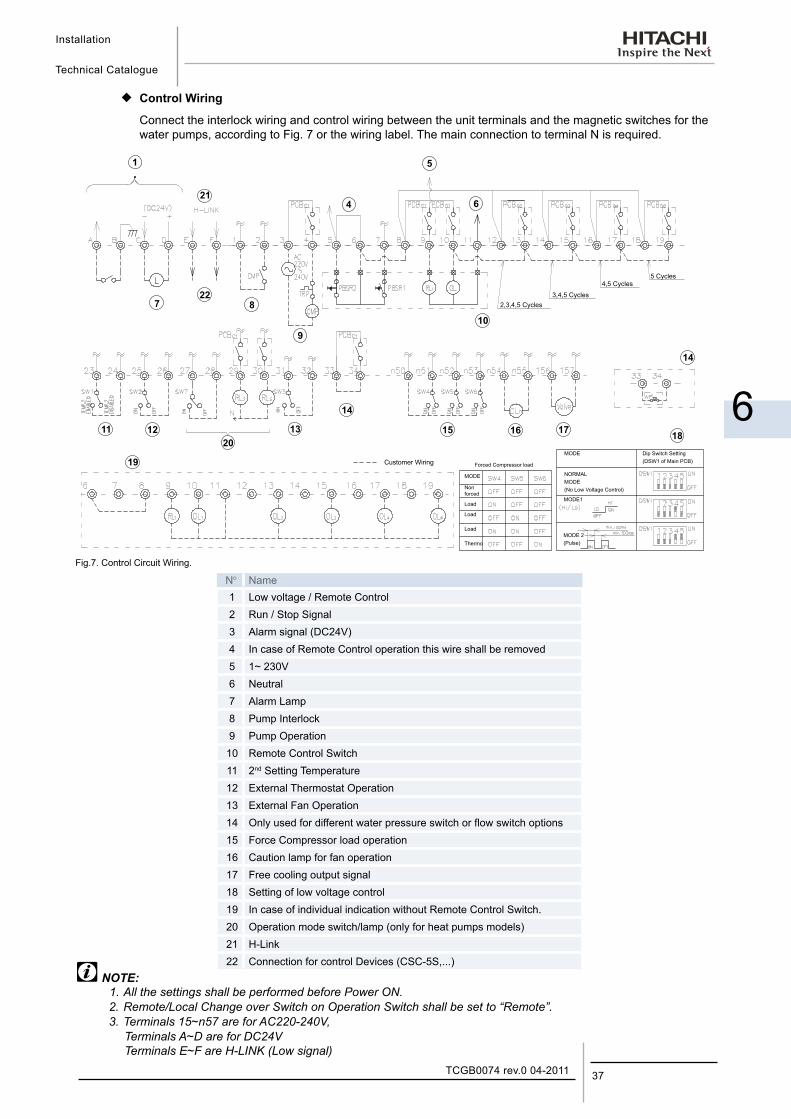
¡ Control Wiring
Connect the interlock wiring and control wiring between the unit terminals and the magnetic switches for the water pumps, according to Fig. 7 or the wiring label. The main connection to terminal N is required.
1
21
4
5
6
722
9
8
10
11 12
20
13
14
15 16 17
14
18
19
Fig.7. Control Circuit Wiring.
N° Name1 Low voltage / Remote Control2 Run / Stop Signal3 Alarm signal (DC24V)4 In case of Remote Control operation this wire shall be removed5 1~ 230V6 Neutral 7 Alarm Lamp8 Pump Interlock9 Pump Operation10 Remote Control Switch11 2nd Setting Temperature12 External Thermostat Operation13 External Fan Operation14 Only used for different water pressure switch or flow switch options15 Force Compressor load operation16 Caution lamp for fan operation17 Free cooling output signal18 Setting of low voltage control19 In case of individual indication without Remote Control Switch.20 Operation mode switch/lamp (only for heat pumps models)21 H-Link22 Connection for control Devices (CSC-5S,...)
NOTE:1. All the settings shall be performed before Power ON.
2. Remote/Local Change over Switch on Operation Switch shall be set to “Remote”. 3. Terminals 15~n57 are for AC220-240V,
Terminals A~D are for DC24V Terminals E~F are H-LINK (Low signal)
Customer WiringMODE Dip Switch Setting
(DSW1 of Main PCB)
NORMALMODE(No Low Voltage Control)
MODE1
MODE 2(Pulse)
MODE
Non forced
Load
Load
Load
Thermo
Forced Compressor load
2,3,4,5 Cycles
5 Cycles4,5 Cycles
3,4,5 Cycles
Installation
Technical Catalogue
TCGB0074 rev.0 04-201138
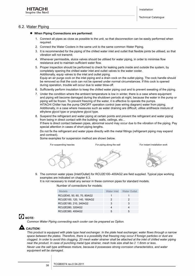
6.2. Water Piping ¡ When Piping Connections are performed:
1. Connect all pipes as close as possible to the unit, so that disconnection can be easily performed when required.
2. Connect the Water Coolers in the same unit to the same common Water Piping.3. It is recommended for the piping of the chilled water inlet and outlet that flexible joints be utilised, so that
vibration will not transmit.4. Whenever permissible, sluice valves should be utilised for water piping, in order to minimise flow
resistance and to maintain sufficient water flow.5. Proper inspection should be performed to check for leaking parts inside and outside the system, by
completely opening the chilled water inlet and outlet valves to the water cooler. Additionally, equip valves to the inlet and outlet piping. Equip an air purge cock on the inlet piping and a drain cock on the outlet piping. The cock handle should be removed so that the cock can not be opened under normal circumstances. If this cock is opened during operation, trouble will occur due to water blow-off.
6. Sufficiently perform insulation to keep the chilled water piping cool and to prevent sweating of the piping.7. Under the condition where the ambient temperature is low in winter, there is a case where equipment
and piping will become damaged during the shutdown periods at night, because the water in the pump or piping will be frozen. To prevent freezing of the water, it is effective to operate the pumps. HITACHI Chiller has the pump ON/OFF operation control (see wiring diagram) water from piping. Additionally, in a case where measures such as water draining are difficult, utilise antifreeze mixture of ethylene glycol type or propylene glycol type.
8. Suspend the refrigerant and water piping at certain points and prevent the refrigerant and water piping from being in direct contact with the building: walls, ceilings, etc... If there is direct contact between pipes, abnormal sound may occur due to the vibration of the piping. Pay special attention in cases of short piping lengths.
Do not fix the refrigerant and water pipes directly with the metal fittings (refrigerant piping may expand and contract). Some examples for suspension method are shown below.
For suspending heavies For piping along the wall For instant installation work
9. The common water pipes (Inlet/Outlet) for RCU2E100∼400AG2 are field supplied. Typical pipe working examples are indicated on chapter 6.3. It is not necessary to install any sensor in these common pipes for standard models.
Number of connections for models:
Models Water Inlet Water OutletRCU2E40, 50, 60, 70, 80AG2 1 1RCU2E100, 120, 140, 160AG2 2 2RCU2E180, 210, 240AG2 3 3RCU2E280, 320AG2 4 4RCU2E380, 400AG2 5 5
NOTE:Common Water Piping connecting each cooler can be prepared as Option.
CAUTION:This product is equipped with plate type heat exchanger. In the plate heat exchanger, water flows through a narrow space between the plates. Therefore, there is a possibility that freezing may occur if foreign particles or dust are clogged. In order to avoid this clogging, 20 mesh water strainer shall be attached at the inlet of chilled water piping near the product. In case of punching metal type strainer, mesh hole size shall be ∅ 1.6mm or less. Never use the salt type antifreeze mixture, because it possesses strong corrosion characteristics, and water equipment will be damaged.
Installation
Technical Catalogue
6
39TCGB0074 rev.0 04-2011
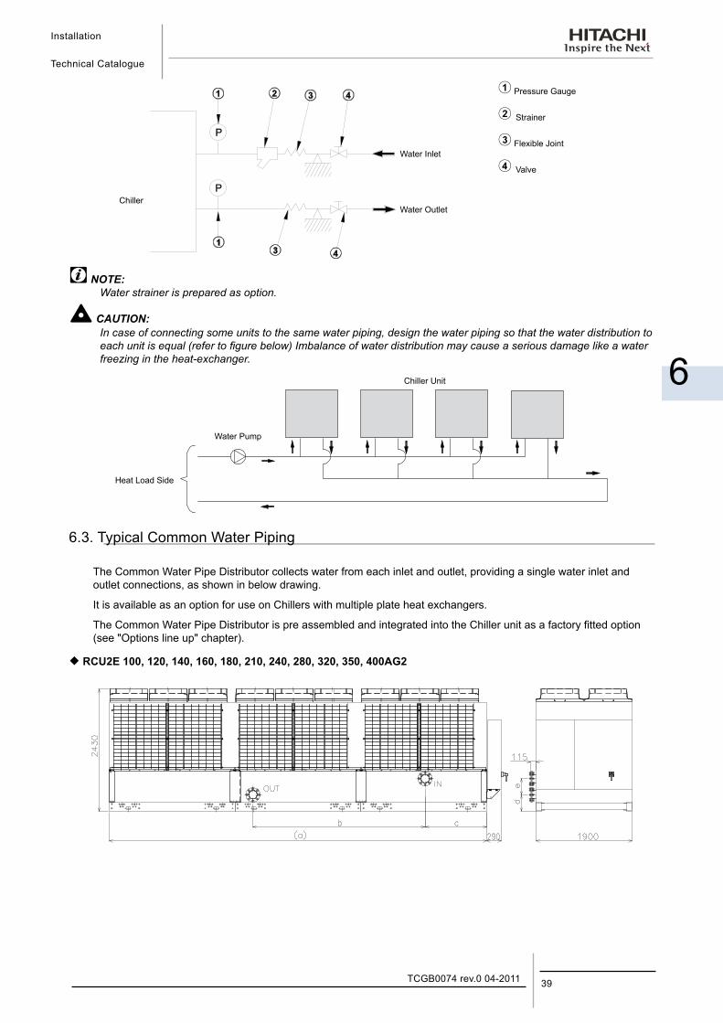
ChillerWater Outlet
Water Inlet
Pressure Gauge
Strainer
Flexible Joint
Valve
NOTE:Water strainer is prepared as option.
CAUTION:In case of connecting some units to the same water piping, design the water piping so that the water distribution to each unit is equal (refer to figure below) Imbalance of water distribution may cause a serious damage like a water freezing in the heat-exchanger.
Chiller Unit
Water Pump
Heat Load Side
6.3. Typical Common Water Piping
The Common Water Pipe Distributor collects water from each inlet and outlet, providing a single water inlet and outlet connections, as shown in below drawing.
It is available as an option for use on Chillers with multiple plate heat exchangers.
The Common Water Pipe Distributor is pre assembled and integrated into the Chiller unit as a factory fitted option (see "Options line up" chapter).
¡ RCU2E 100, 120, 140, 160, 180, 210, 240, 280, 320, 350, 400AG2
Installation
Technical Catalogue
TCGB0074 rev.0 04-201140
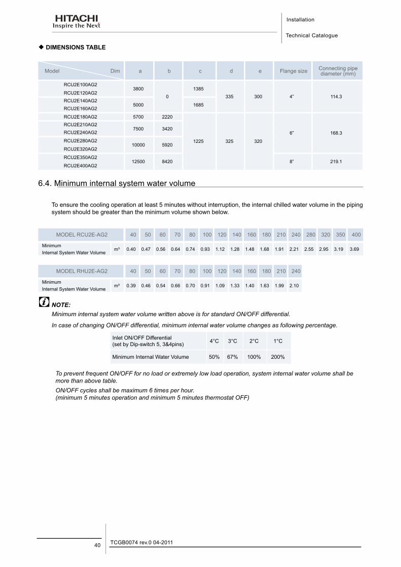
¡ DIMENSIONS TABLE
Model Dim a b c d e Flange size Connecting pipe diameter (mm)
RCU2E100AG23800
01385
335 300 4” 114.3RCU2E120AG2RCU2E140AG2
5000 1685RCU2E160AG2
RCU2E180AG2 5700 2220
1225 325 320
6” 168.3
RCU2E210AG27500 3420
RCU2E240AG2
RCU2E280AG210000 5920
RCU2E320AG2
RCU2E350AG212500 8420 8” 219.1
RCU2E400AG2
6.4. Minimum internal system water volume
To ensure the cooling operation at least 5 minutes without interruption, the internal chilled water volume in the piping system should be greater than the minimum volume shown below.
MODEL RCU2E-AG2 40 50 60 70 80 100 120 140 160 180 210 240 280 320 350 400
Minimumm³ 0.40 0.47 0.56 0.64 0.74 0.93 1.12 1.28 1.48 1.68 1.91 2.21 2.55 2.95 3.19 3.69
Internal System Water Volume
MODEL RHU2E-AG2 40 50 60 70 80 100 120 140 160 180 210 240
Minimumm³ 0.39 0.46 0.54 0.66 0.70 0.91 1.09 1.33 1.40 1.63 1.99 2.10
Internal System Water Volume
NOTE:Minimum internal system water volume written above is for standard ON/OFF differential.
In case of changing ON/OFF differential, minimum internal water volume changes as following percentage.
Inlet ON/OFF Differential (set by Dip-switch 5, 3&4pins) 4°C 3°C 2°C 1°C
Minimum Internal Water Volume 50% 67% 100% 200%
To prevent frequent ON/OFF for no load or extremely low load operation, system internal water volume shall be more than above table.ON/OFF cycles shall be maximum 6 times per hour. (minimum 5 minutes operation and minimum 5 minutes thermostat OFF)
Installation
Technical Catalogue
6
41TCGB0074 rev.0 04-2011
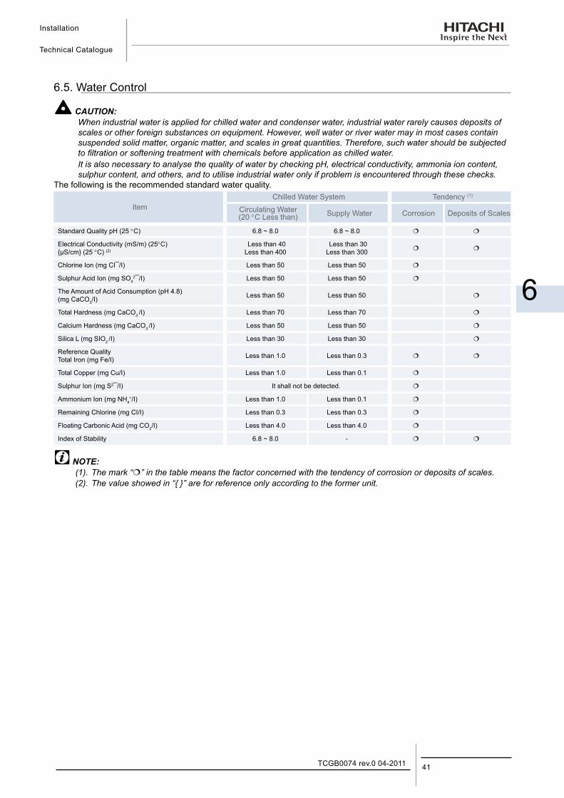
6.5. Water Control
CAUTION:When industrial water is applied for chilled water and condenser water, industrial water rarely causes deposits of scales or other foreign substances on equipment. However, well water or river water may in most cases contain suspended solid matter, organic matter, and scales in great quantities. Therefore, such water should be subjected to filtration or softening treatment with chemicals before application as chilled water.It is also necessary to analyse the quality of water by checking pH, electrical conductivity, ammonia ion content, sulphur content, and others, and to utilise industrial water only if problem is encountered through these checks.
The following is the recommended standard water quality.
ItemChilled Water System Tendency (1)
Circulating Water (20 °C Less than) Supply Water Corrosion Deposits of Scales
Standard Quality pH (25 °C) 6.8 ~ 8.0 6.8 ~ 8.0
Electrical Conductivity (mS/m) (25°C){µS/cm} (25 °C) (2)
Less than 40 Less than 400
Less than 30 Less than 300
Chlorine Ion (mg CI¯/I) Less than 50 Less than 50
Sulphur Acid Ion (mg SO42¯/I) Less than 50 Less than 50
The Amount of Acid Consumption (pH 4.8) (mg CaCO3/I)
Less than 50 Less than 50
Total Hardness (mg CaCO3 /I) Less than 70 Less than 70
Calcium Hardness (mg CaCO3 /I) Less than 50 Less than 50
Silica L (mg SIO2 /I) Less than 30 Less than 30
Reference Quality Total Iron (mg Fe/I) Less than 1.0 Less than 0.3
Total Copper (mg Cu/I) Less than 1.0 Less than 0.1
Sulphur Ion (mg S2¯/I) It shall not be detected.
Ammonium Ion (mg NH4+/I) Less than 1.0 Less than 0.1
Remaining Chlorine (mg CI/I) Less than 0.3 Less than 0.3
Floating Carbonic Acid (mg CO2/I) Less than 4.0 Less than 4.0
Index of Stability 6.8 ~ 8.0 -
NOTE:(1). The mark “” in the table means the factor concerned with the tendency of corrosion or deposits of scales.(2). The value showed in “{ }” are for reference only according to the former unit.
Installation
Technical Catalogue
TCGB0074 rev.0 04-201142
6.6. BMS gateways
6.6.1. HARDC70-CE1 (OP) - LonWorks® interface.
¡ General Features − There are two options for water chillers:
- HARC-70CE1
- HARC-70CE1 OP
− Gateway interface with BMS LonWorks systems (installations with intelligent BMS control).
− With the HARC-70CE1 connection to a H-LINK network, it is possible to control 4 setting points and 7 monitoring points of up to 4 chillers.
− With the HARC-70CE1 OP connection to a H-LINK network, it is possible to control 4 setting points and up to 44 monitoring points of one chiller unit.
− The HARC-70CE1 (OP) remote controls offer the option of self-checking their own status.
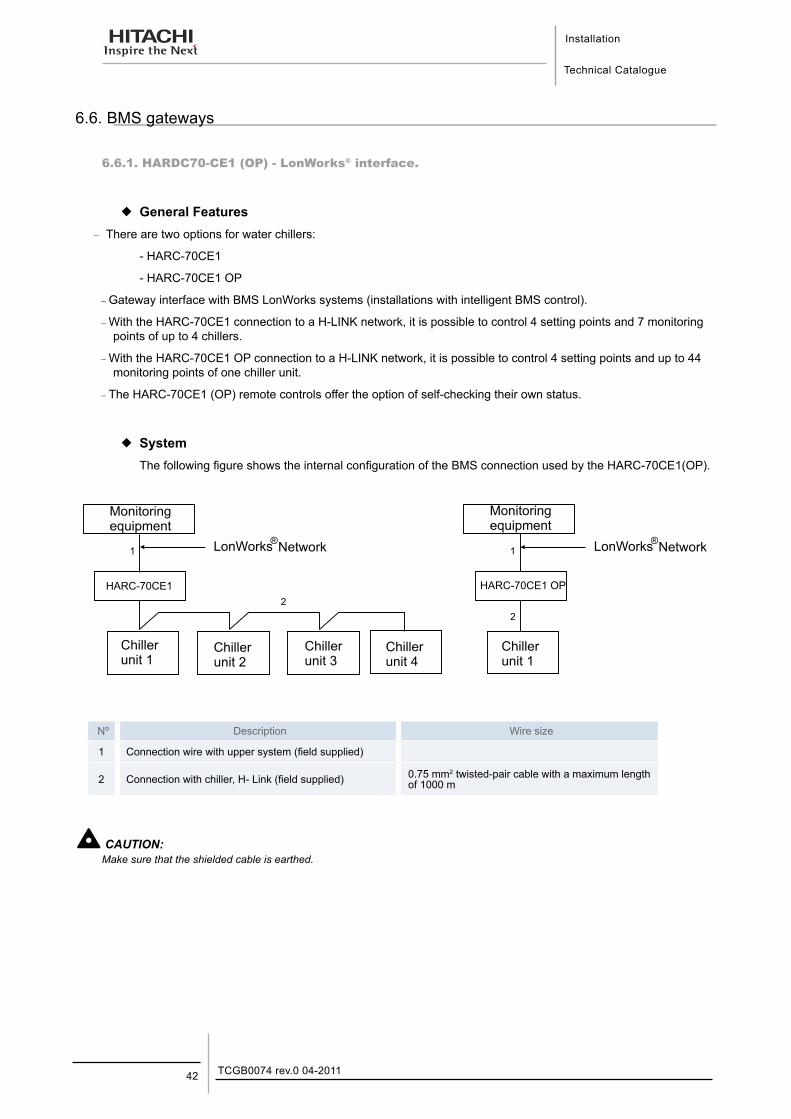
¡ SystemThe following figure shows the internal configuration of the BMS connection used by the HARC-70CE1(OP).
®LonWorks
®LonWorks1 1
2
2
Nº Description Wire size
1 Connection wire with upper system (field supplied)
2 Connection with chiller, H- Link (field supplied) 0.75 mm2 twisted-pair cable with a maximum length of 1000 m
CAUTION:Make sure that the shielded cable is earthed.
Installation
Technical Catalogue
6
43TCGB0074 rev.0 04-2011
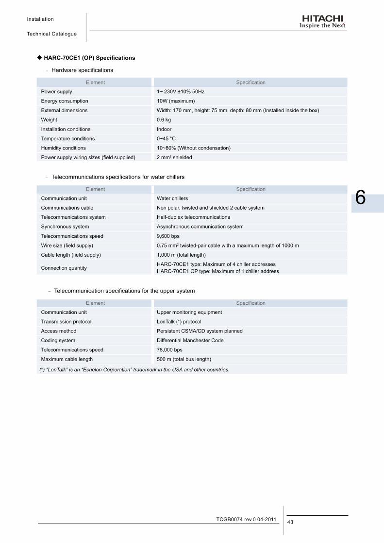
¡ HARC-70CE1 (OP) Specifications
− Hardware specifications
Element Specification
Power supply 1~ 230V ±10% 50Hz
Energy consumption 10W (maximum)
External dimensions Width: 170 mm, height: 75 mm, depth: 80 mm (Installed inside the box)
Weight 0.6 kg
Installation conditions Indoor
Temperature conditions 0~45 °C
Humidity conditions 10~80% (Without condensation)
Power supply wiring sizes (field supplied) 2 mm2 shielded
− Telecommunications specifications for water chillers
Element Specification
Communication unit Water chillers
Communications cable Non polar, twisted and shielded 2 cable system
Telecommunications system Half-duplex telecommunications
Synchronous system Asynchronous communication system
Telecommunications speed 9,600 bps
Wire size (field supply) 0.75 mm2 twisted-pair cable with a maximum length of 1000 m
Cable length (field supply) 1,000 m (total length)
Connection quantityHARC-70CE1 type: Maximum of 4 chiller addressesHARC-70CE1 OP type: Maximum of 1 chiller address
− Telecommunication specifications for the upper system
Element Specification
Communication unit Upper monitoring equipment
Transmission protocol LonTalk (*) protocol
Access method Persistent CSMA/CD system planned
Coding system Differential Manchester Code
Telecommunications speed 78,000 bps
Maximum cable length 500 m (total bus length)
(*) “LonTalk” is an “Echelon Corporation” trademark in the USA and other countries.
Installation
Technical Catalogue
TCGB0074 rev.0 04-201144
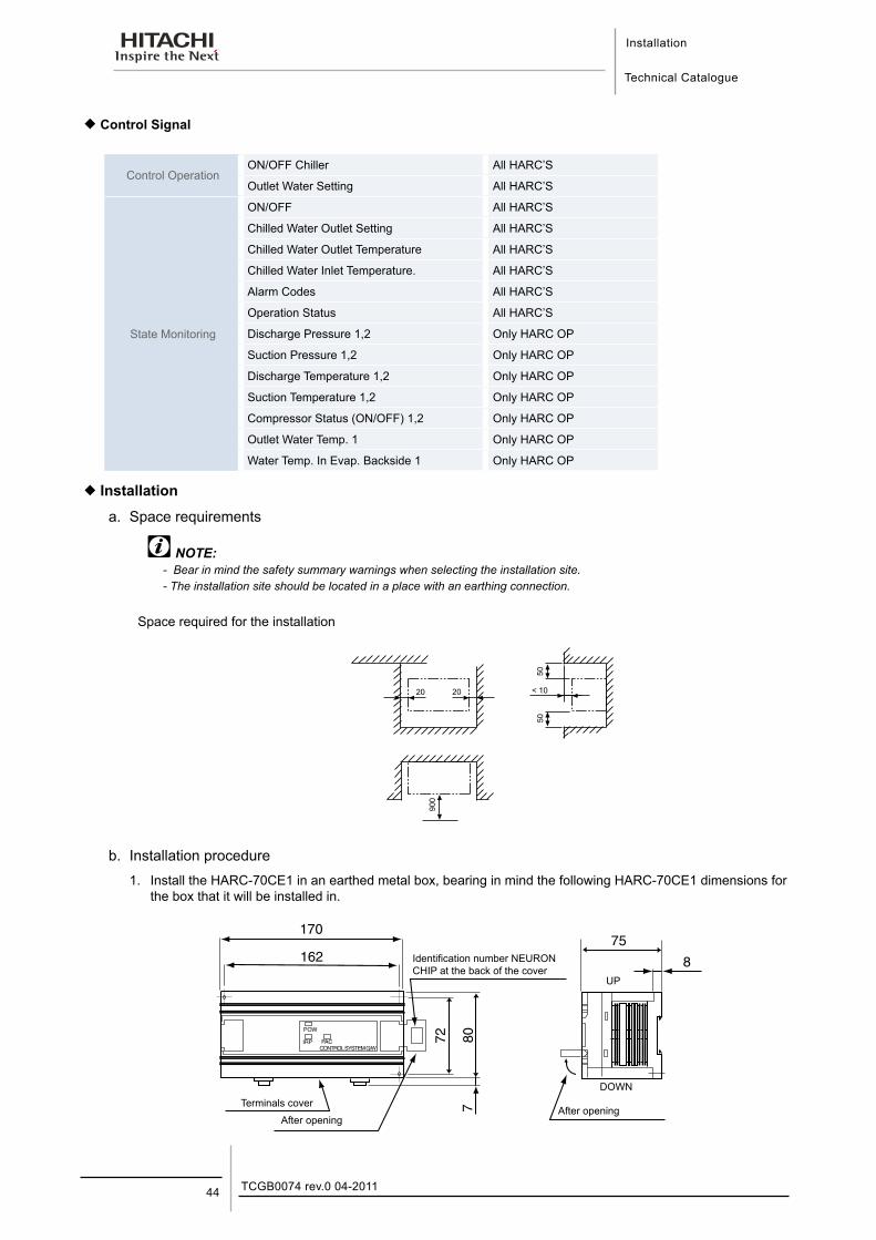
¡ Control Signal
Control OperationON/OFF Chiller All HARC’S
Outlet Water Setting All HARC’S
State Monitoring
ON/OFF All HARC’S
Chilled Water Outlet Setting All HARC’S
Chilled Water Outlet Temperature All HARC’S
Chilled Water Inlet Temperature. All HARC’S
Alarm Codes All HARC’S
Operation Status All HARC’S
Discharge Pressure 1,2 Only HARC OP
Suction Pressure 1,2 Only HARC OP
Discharge Temperature 1,2 Only HARC OP
Suction Temperature 1,2 Only HARC OP
Compressor Status (ON/OFF) 1,2 Only HARC OP
Outlet Water Temp. 1 Only HARC OP
Water Temp. In Evap. Backside 1 Only HARC OP
¡ Installation
a. Space requirements
NOTE:- Bear in mind the safety summary warnings when selecting the installation site.- The installation site should be located in a place with an earthing connection.
Space required for the installation
b. Installation procedure 1. Install the HARC-70CE1 in an earthed metal box, bearing in mind the following HARC-70CE1 dimensions for
the box that it will be installed in.
POW
IRP PACCONTROL SYSTEM G/W
170
162
72 807
75
8
After opening
DOWN
UP
Identification number NEURON CHIP at the back of the cover
After opening
Terminals cover
Installation
Technical Catalogue
6
45TCGB0074 rev.0 04-2011
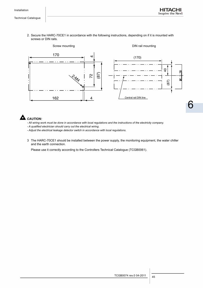
2. Secure the HARC-70CE1 in accordance with the following instructions, depending on if it is mounted with screws or DIN rails.
170 4
4162
72 (87)2-M4
(170)
40(8
7)
Screw mounting DIN rail mounting
Central rail DIN line
CAUTION:- All wiring work must be done in accordance with local regulations and the instructions of the electricity company.- A qualified electrician should carry out the electrical wiring.- Adjust the electrical leakage detector switch in accordance with local regulations.
3 The HARC-70CE1 should be installed between the power supply, the monitoring equipment, the water chiller and the earth connection.
Please use it correctly according to the Controllers Technical Catalogue (TCGB0061).
Installation
Technical Catalogue
TCGB0074 rev.0 04-201146
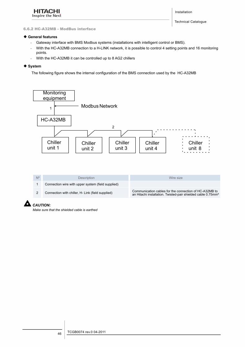
6.6.2 HC-A32MB - ModBus interface
¡ General features − Gateway interface with BMS Modbus systems (installations with intelligent control or BMS). − With the HC-A32MB connection to a H-LINK network, it is possible to control 4 setting points and 16 monitoring
points. − With the HC-A32MB it can be controlled up to 8 AG2 chillers
¡ System
The following figure shows the internal configuration of the BMS connection used by the HC-A32MB
8
1
2
Nº Description Wire size
1 Connection wire with upper system (field supplied)
2 Connection with chiller, H- Link (field supplied) Communication cables for the connection of HC-A32MB to an Hitachi installation. Twisted-pair shielded cable 0.75mm²
CAUTION:Make sure that the shielded cable is earthed
Installation
Technical Catalogue
6
47TCGB0074 rev.0 04-2011
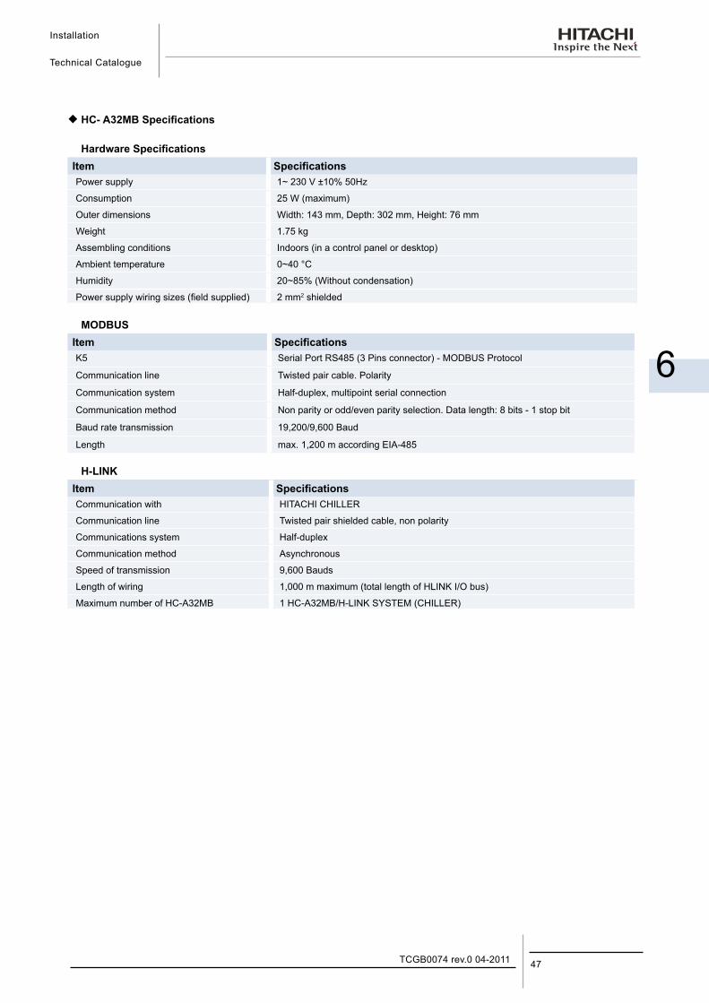
¡ HC- A32MB Specifications
Hardware SpecificationsItem SpecificationsPower supply 1~ 230 V ±10% 50Hz
Consumption 25 W (maximum)
Outer dimensions Width: 143 mm, Depth: 302 mm, Height: 76 mm
Weight 1.75 kg
Assembling conditions Indoors (in a control panel or desktop)
Ambient temperature 0~40 °C
Humidity 20~85% (Without condensation)
Power supply wiring sizes (field supplied) 2 mm2 shielded
MODBUSItem SpecificationsK5 Serial Port RS485 (3 Pins connector) - MODBUS Protocol
Communication line Twisted pair cable. Polarity
Communication system Half-duplex, multipoint serial connection
Communication method Non parity or odd/even parity selection. Data length: 8 bits - 1 stop bit
Baud rate transmission 19,200/9,600 Baud
Length max. 1,200 m according EIA-485
H-LINKItem SpecificationsCommunication with HITACHI CHILLER
Communication line Twisted pair shielded cable, non polarity
Communications system Half-duplex
Communication method Asynchronous
Speed of transmission 9,600 Bauds
Length of wiring 1,000 m maximum (total length of HLINK I/O bus)
Maximum number of HC-A32MB 1 HC-A32MB/H-LINK SYSTEM (CHILLER)
Installation
Technical Catalogue
TCGB0074 rev.0 04-201148
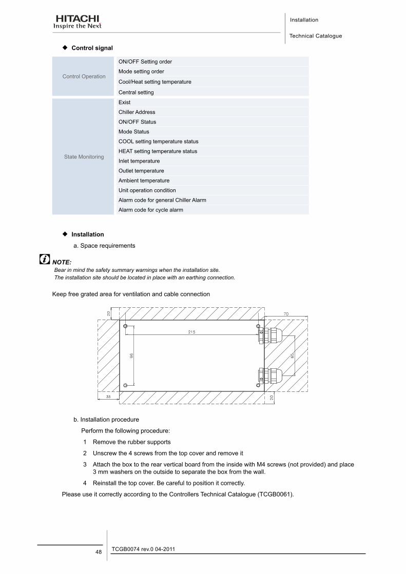
¡ Control signal
Control Operation
ON/OFF Setting order
Mode setting order
Cool/Heat setting temperature
Central setting
State Monitoring
Exist
Chiller Address
ON/OFF Status
Mode Status
COOL setting temperature status
HEAT setting temperature status
Inlet temperature
Outlet temperature
Ambient temperature
Unit operation condition
Alarm code for general Chiller Alarm
Alarm code for cycle alarm
¡ Installation
a. Space requirements
NOTE:Bear in mind the safety summary warnings when the installation site.The installation site should be located in place with an earthing connection.
Keep free grated area for ventilation and cable connection
b. Installation procedure
Perform the following procedure:
1 Remove the rubber supports
2 Unscrew the 4 screws from the top cover and remove it
3 Attach the box to the rear vertical board from the inside with M4 screws (not provided) and place 3 mm washers on the outside to separate the box from the wall.
4 Reinstall the top cover. Be careful to position it correctly.
Please use it correctly according to the Controllers Technical Catalogue (TCGB0061).
Installation
Technical Catalogue
6
49TCGB0074 rev.0 04-2011
6.7. Remote controllers6.7.1. CSC-5S – Central Station
¡ General features:
− 8 chiller and 8 CSC-5S central remote control addresses can be connected on each H-LINK
− Up to 8 central remote controls (CSC-5S) can be connected to a H-LINK.
− Basic functions, heat/cold mode and temperature setting.
− When a problem occurs, an alarm code will immediately be displayed with detailed information about the error.
− A standard external input terminal is included for possible connection to a timer.
− The external signals control the following functions
Start/Stop.
Operation mode (Cooling/Heating).
Temperature setting (Cold/Heat).
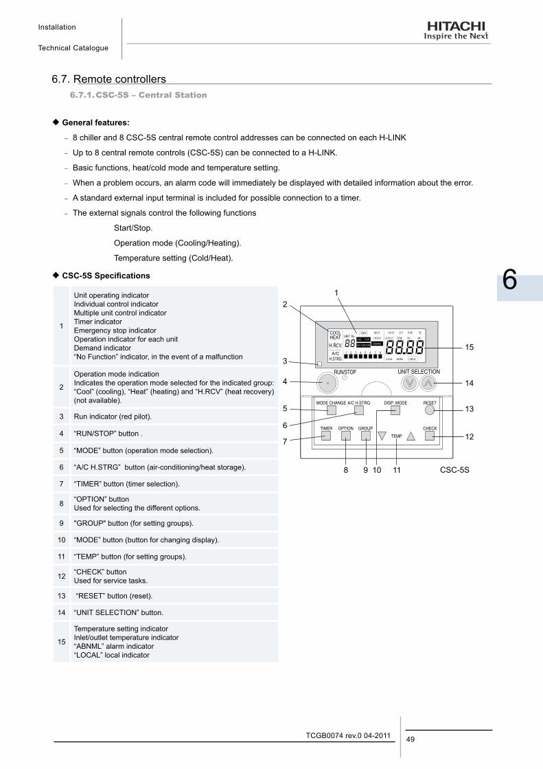
¡ CSC-5S Specifications
1
Unit operating indicator Individual control indicator Multiple unit control indicator Timer indicator Emergency stop indicator Operation indicator for each unit Demand indicator “No Function” indicator, in the event of a malfunction
2
Operation mode indication Indicates the operation mode selected for the indicated group: “Cool” (cooling), “Heat” (heating) and “H.RCV” (heat recovery) (not available).
3 Run indicator (red pilot).
4 “RUN/STOP” button .
5 “MODE” button (operation mode selection).
6 “A/C H.STRG” button (air-conditioning/heat storage).
7 “TIMER” button (timer selection).
8 “OPTION” button Used for selecting the different options.
9 "GROUP" button (for setting groups).
10 “MODE” button (button for changing display).
11 “TEMP” button (for setting groups).
12 “CHECK” button Used for service tasks.
13 “RESET” button (reset).
14 “UNIT SELECTION” button.
15
Temperature setting indicator Inlet/outlet temperature indicator “ABNML” alarm indicator “LOCAL” local indicator
Installation
Technical Catalogue
TCGB0074 rev.0 04-201150
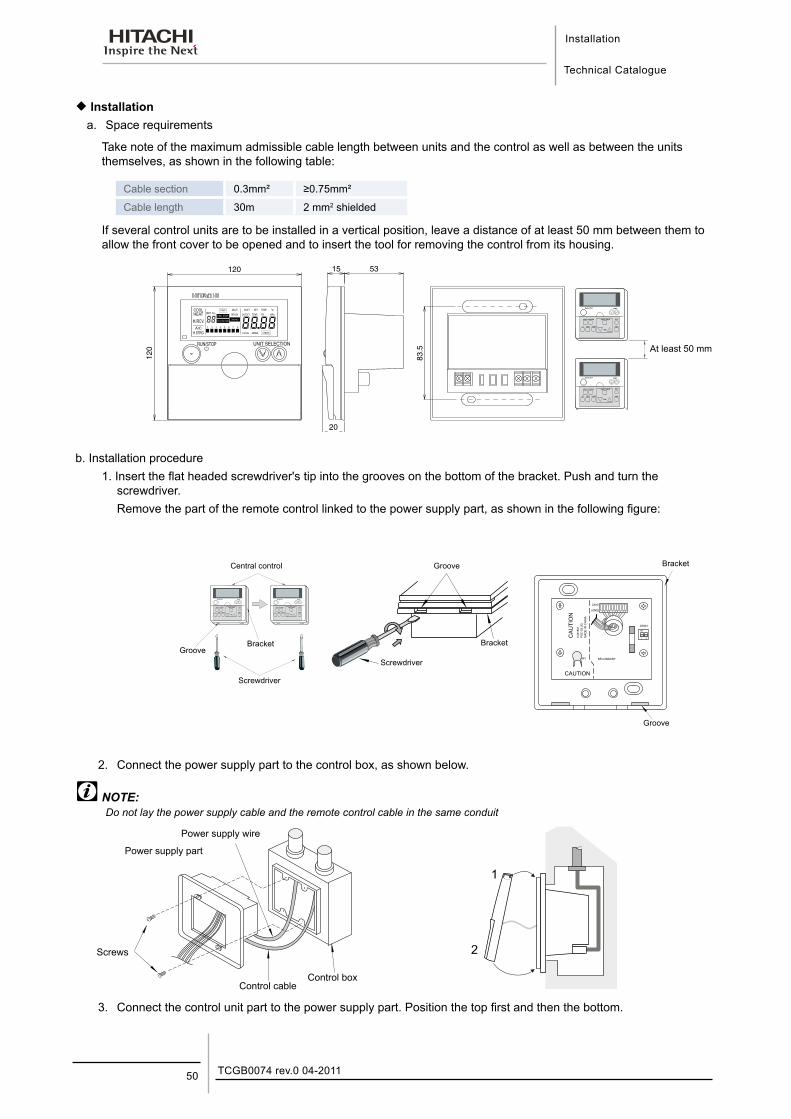
¡ Installationa. Space requirements
Take note of the maximum admissible cable length between units and the control as well as between the units themselves, as shown in the following table:
Cable section 0.3mm² ≥0.75mm²
Cable length 30m 2 mm2 shielded
If several control units are to be installed in a vertical position, leave a distance of at least 50 mm between them to allow the front cover to be opened and to insert the tool for removing the control from its housing.
53
83.5
120
120
15
20
RUN/STOP UNIT SELECTION
EMG. STOP
MULTI
INDVDL
INLET
OUTLET
SET
TEMP.
TEMP.
PR. MPa
CHECKABNMLLOCAL
At least 50 mm
b. Installation procedure1. Insert the flat headed screwdriver's tip into the grooves on the bottom of the bracket. Push and turn the
screwdriver.Remove the part of the remote control linked to the power supply part, as shown in the following figure:
Central control
BracketGroove
Screwdriver
Groove
Bracket
Screwdriver
Groove
Bracket
2. Connect the power supply part to the control box, as shown below.
NOTE:Do not lay the power supply cable and the remote control cable in the same conduit
Power supply wire
Power supply part
Screws
Control cableControl box
3. Connect the control unit part to the power supply part. Position the top first and then the bottom.
Installation
Technical Catalogue
6
51TCGB0074 rev.0 04-2011
CAUTION:- Do not position all the signal cables together with the power supply cable and other signal cables. The noise caused by these
cables could lead to the malfunction of the remote control and chiller unit. If the signal cables are next to the power cables and any other signal cables, maintain a distance of at least 15 cm between the signal cables and other cables, or pass the signal cables through a metal conduit which is earthed at one end.
- If the power supply cable is accidentally connected to the terminal board for the transmission signal and voltage is applied, the fuse will blow to protect the printed circuit board. In this case, this remote control can operate without the fuse, if pin no. 2 of DSW3 is set to the ON position.
- If the PSC-A1T remote control's timer is used, set the same address no. for the remote control and the timer.- Make sure that the wiring is correct (do place the signal cables together with the electricity cables). Incorrect wiring could cause
the remote control to malfunction- Before installing the wiring, switch off the power supply to the air conditioning system and central control unit.- Installing the wiring while the central control power supply is switched on may cause the central control unit to malfunction.
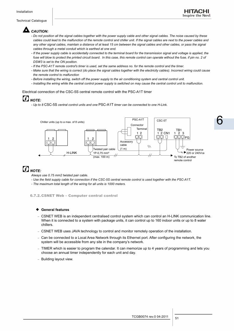
Electrical connection of the CSC-5S central remote control with the PSC-A1T timer
NOTE:- Up to 8 CSC-5S central control units and one PSC-A1T timer can be connected to one H-Link.
Chiller units (up to a max. of 8 units)PSC-A1T CSC-5T
Twisted pair cable1P-0,75 mm²(max. 100 m)
Accessory cable(1 m) Power source
220 or 240VcaTo TB2 of another remote control
ConnectorTerminal
NOTE:Always use 0.75 mm2 twisted pair cable.- Use the field supply cable for connection if the CSC-5S central remote control is used together with the PSC-A1T.- The maximum total length of the wiring for all units is 1000 meters.
6.7.2. CSNET Web – Computer central control
¡ General features
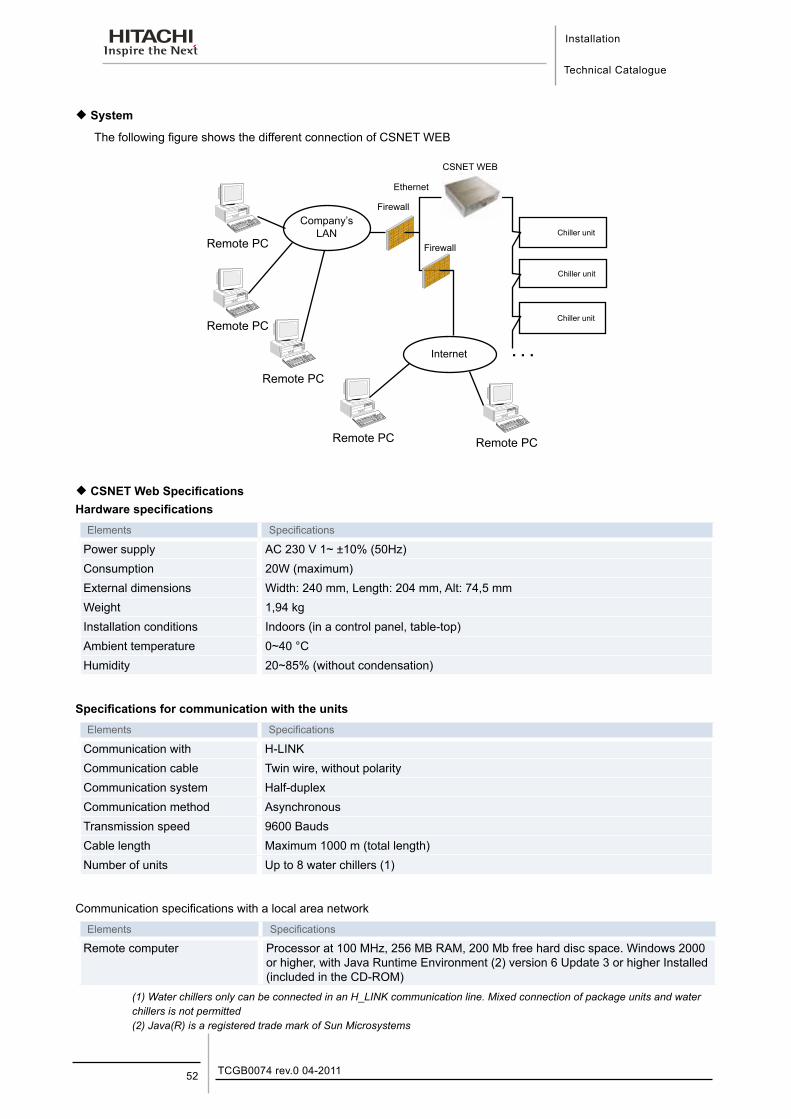
− CSNET WEB is an independent centralised control system which can control an H-LINK communication line. When it is connected to a system with package units, it can control up to 160 indoor units or up to 8 water chillers.
− CSNET WEB uses JAVA technology to control and monitor remotely operation of the installation.
− Can be connected to a Local Area Network through its Ethernet port. After configuring the network, the system will be accessible from any site in the company’s network.
− TIMER which is easier to program the calendar. It can memorize up to 4 years of programming and lets you choose an annual timer independently for each unit and day.
− Building layout view.
Installation
Technical Catalogue
TCGB0074 rev.0 04-201152
¡ System
The following figure shows the different connection of CSNET WEB
Chiller unit
Chiller unit
Chiller unit
Remote PC
Company’s LAN
Remote PC
Remote PC
Remote PC Remote PC
Firewall
Internet . . .
CSNET WEB
Firewall
Ethernet
¡ CSNET Web Specifications Hardware specifications
Elements Specifications
Power supply AC 230 V 1~ ±10% (50Hz)Consumption 20W (maximum)External dimensions Width: 240 mm, Length: 204 mm, Alt: 74,5 mmWeight 1,94 kgInstallation conditions Indoors (in a control panel, table-top)Ambient temperature 0~40 °CHumidity 20~85% (without condensation)
Specifications for communication with the unitsElements Specifications
Communication with H-LINKCommunication cable Twin wire, without polarity Communication system Half-duplexCommunication method AsynchronousTransmission speed 9600 BaudsCable length Maximum 1000 m (total length)Number of units Up to 8 water chillers (1)
Communication specifications with a local area network
Elements Specifications
Remote computer Processor at 100 MHz, 256 MB RAM, 200 Mb free hard disc space. Windows 2000 or higher, with Java Runtime Environment (2) version 6 Update 3 or higher Installed (included in the CD-ROM)
(1) Water chillers only can be connected in an H_LINK communication line. Mixed connection of package units and water chillers is not permitted(2) Java(R) is a registered trade mark of Sun Microsystems
Installation
Technical Catalogue
6
53TCGB0074 rev.0 04-2011
¡ Installation
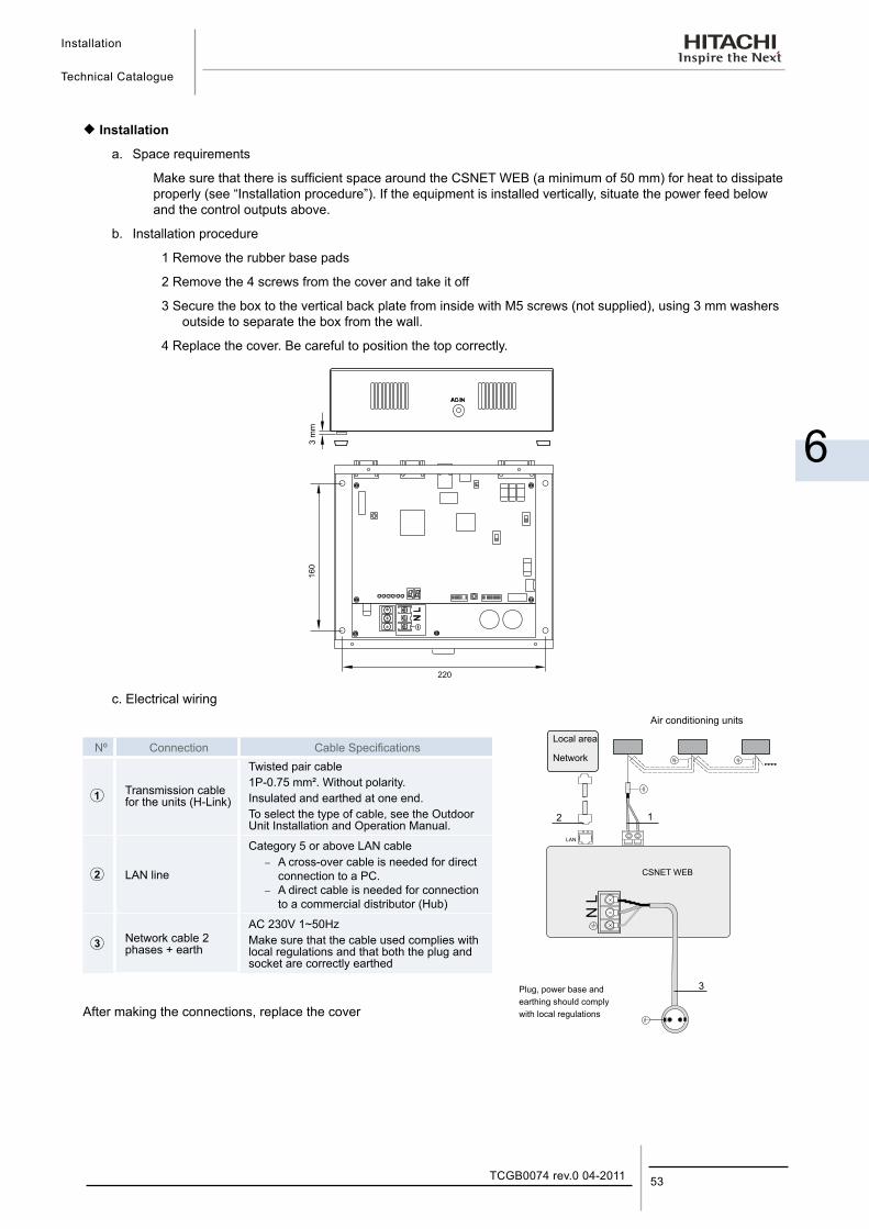
a. Space requirements
Make sure that there is sufficient space around the CSNET WEB (a minimum of 50 mm) for heat to dissipate properly (see “Installation procedure”). If the equipment is installed vertically, situate the power feed below and the control outputs above.
b. Installation procedure
1 Remove the rubber base pads
2 Remove the 4 screws from the cover and take it off
3 Secure the box to the vertical back plate from inside with M5 screws (not supplied), using 3 mm washers outside to separate the box from the wall.
4 Replace the cover. Be careful to position the top correctly.
AC IN
3m
m
c. Electrical wiring
Nº Connection Cable Specifications
Transmission cable for the units (H-Link)
Twisted pair cable1P-0.75 mm². Without polarity.Insulated and earthed at one end.To select the type of cable, see the Outdoor Unit Installation and Operation Manual.
LAN line
Category 5 or above LAN cable − A cross-over cable is needed for direct
connection to a PC. − A direct cable is needed for connection
to a commercial distributor (Hub)
Network cable 2 phases + earth
AC 230V 1~50HzMake sure that the cable used complies with local regulations and that both the plug and socket are correctly earthed
After making the connections, replace the cover
NL
LAN
CSNET WEB
Plug, power base andearthing should complywith local regulations
Local area
Network
Air conditioning units
12
3
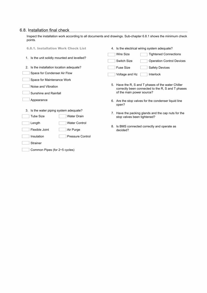
6.8. Installation final check Inspect the installation work according to all documents and drawings. Sub-chapter 6.8.1 shows the minimum check points.
6.8.1. Installation Work Check List
1. Is the unit solidly mounted and levelled?
2. Is the installation location adequate?
Space for Condenser Air Flow
Space for Maintenance Work
Noise and Vibration
Sunshine and Rainfall
Appearance
3. Is the water piping system adequate?
Tube Size Water Drain
Length Water Control
Flexible Joint Air Purge
Insulation Pressure Control
Strainer
Common Pipes (for 2~5 cycles)
4. Is the electrical wiring system adequate?
Wire Size Tightened Connections
Switch Size Operation Control Devices
Fuse Size Safety Devices
Voltage and Hz Interlock
5. Have the R, S and T phases of the water Chiller correctly been connected to the R, S and T phases of the main power source?
6. Are the stop valves for the condenser liquid line open?
7. Have the packing glands and the cap nuts for the stop valves been tightened?
8. Is BMS connected correctly and operate as decided?
Test Running
Technical Catalogue
7
7. Te s t R u n n i n g
55TCGB0074 rev.0 04-2011
Contents
7. Test running .................................................................................................................557.1. Preparation .............................................................................................................................................. 56
7.2. Test running ............................................................................................................................................. 56
7.3. Instructions after test running .................................................................................................................. 56
Test Running
Technical Catalogue
TCGB0074 rev.0 04-201156
7.1. Preparation
¡ Tools and instruments−− High Pressure Compound Gauge. Low Pressure Compound Gauge. Electrical
Tester and General Tools.−− Remove the foreign particles and substances from the water piping, without going
through the water coolers and clearing the water strainer filter before running. Check to ensure that no foreign particle and substance exists in the water piping.
7.2. Test running
Test running should be performed as follows, when the unit is wired according to the HITACHI standard wiring label.
1. Switch ON the field-supplied pump and it will be started immediately and check the condition and operation state of that.
2. Fully open the liquid outlet stop valve.
3. Set the operation switch to “ON”, and the compressor will be started in a few minutes after this operation.
Test running should be accomplished as follows.
Each rotation direction of two rotors in the compressor is fixed so that a reversal phase protection device is equipped.
However, the rotation direction should be checked with a following method.
Confirm that phases R, S and T for the compressor are correctly connected. The correct phase connection can be checked by a phase sequence indicator. If not, the compressor does not start due to the activation of the reversal phase protection device.
Cut the main switch and interchange two of three terminals, R, S and T on the main terminals at the field connection side in the unit.
− Operate the pump for chilled water and other auxiliary equipment such as fan coil units and Air handling units.
− Check to ensure that the chilled water flows sufficiently and that other auxiliary equipment operates properly.
− Set the switch at the desired temperature.
− Depress the “ON“ push button, the condenser fans will start to operate and the compressor will be started.
− Check the rotation direction of the condenser fans.
− After system operation becomes stabilised, check the discharge and suction pressures by 7-segment on control panel.
− Check to ensure that the thermostat works properly.
− Check to ensure that the control and protective devices work properly.
− Starting timer and unload-starting timer are set at five (5), thirty (30) seconds and three (3) minutes, respectively, in accordance with operation characteristics. Therefore, local adjustment should be avoided.
7.3. Instructions after test running
When the test running is completed, please instruct customers about operation and periodic maintenance methods before leaving the unit, by using this manual. A special attention is required to the following caution:
CAUTION:Do not cut off the power source switch during the operating season. When the power source switch is cut off, the oil heater for screw compressor is not energised, and the compressor might be damaged due to oil foaming at starting.When the operation season starts after long disconnection of the power source switch, please turn on the power source switch 12 hours before starting operation.
CAUTION:Switch On the main power switch, and energise the oil heater for 12 hours before start-up, to sufficiently warm the oil.Check to ensure that valves are correctly opened. If not opened, serious damage will occur to the compressor due to an abnormally high pressure.
DANGER:Switch OFF main interruptor (M.I) for any work inside Electrical Box.
CAUTION:When the unit is wired according to the HITACHI standard wiring shown on the wiring label. Switch ON the main power switch, and energise the oil heater for 12 hours before start-up to sufficiently warm the oil.
NOTE:A loud sound occurs when this compressor is stopped after the normal operation. However, this sound indicates no abnormalities and stops within a few seconds by the activation of the check valve. This sound is due to the reverse rotation of the screw rotors, resulting from the pressure difference between the discharge and the suction pressure.Each compressor may show the different valves of running current due to individual capacity control for each compressor. This is not abnormal.
Controller Adjustment
Technical Catalogue
8
8. C o n t r o l l e r A d j u s t m e n t
57TCGB0074 rev.0 04-2011
Contents
8. Controller adjustment ..................................................................................................578.1. Control System ........................................................................................................................................ 59
8.2. Controller Adjustment .............................................................................................................................. 60
Controller Adjustment
Technical Catalogue
TCGB0074 rev.0 04-201158
SWITCH POSITION
ONOFF ON
ONOFF OFF
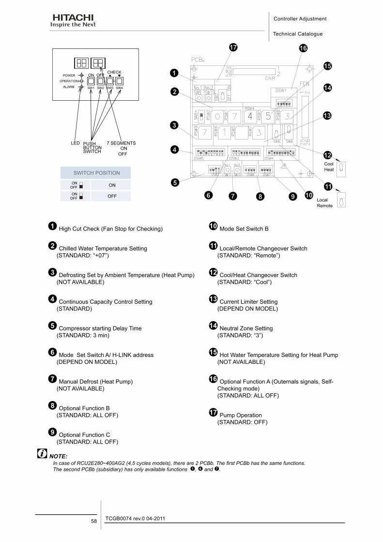
High Cut Check (Fan Stop for Checking)
Chilled Water Temperature Setting(STANDARD: “+07”)
Defrosting Set by Ambient Temperature (Heat Pump)(NOT AVAILABLE)
Continuous Capacity Control Setting(STANDARD)
Compressor starting Delay Time(STANDARD: 3 min)
Mode Set Switch A/ H-LINK address(DEPEND ON MODEL)
Manual Defrost (Heat Pump)(NOT AVAILABLE)
Optional Function B(STANDARD: ALL OFF)
Optional Function C(STANDARD: ALL OFF)
Mode Set Switch B
Local/Remote Changeover Switch(STANDARD: “Remote”)
Cool/Heat Changeover Switch(STANDARD: “Cool”)
Current Limiter Setting(DEPEND ON MODEL)
Neutral Zone Setting(STANDARD: “3”)
Hot Water Temperature Setting for Heat Pump(NOT AVAILABLE)
Optional Function A (Outernals signals, Self-Checking mode) (STANDARD: ALL OFF)
Pump Operation(STANDARD: OFF)
NOTE:In case of RCU2E280~400AG2 (4,5 cycles models), there are 2 PCBb. The first PCBb has the same functions. The second PCBb (subsidiary) has only available functions , and .
LED PUSH BUTTON SWITCH
7 SEGMENTSON
OFF
CoolHeat
LocalRemote
Controller Adjustment
Technical Catalogue
8
59TCGB0074 rev.0 04-2011
8.1. Control SystemElectrical Operation Controls advanced HITACHI Water Chillers are as follows.
¡ Capacity Control
All models are equipped with an unloading system for each compressor, in order to adjust the cooling capacity and to provide precise temperature control for the chilled water, coupled with electronic thermostats.
¡ Control Panel
ON switch, OFF switch, Power Supply Lamp, Operation Lamp, Alarm Lamp, Operation/Alarm Indicator for each refrigerant cycle and check switch are mounted in the Control Panel. The Control Panel is located at a position where easy access is available. Operation/Alarm indicator can display individual alarm codes such as High-Cut, Low-Cut etc. This function is very useful for detecting what alarm has occurred. Check switches are for checking chilled water temperature and alarm occurrence data. Chilled water temperature setting switches, ON/OFF Differential Setting Switches, Remote-Local Switch and so on are located at the rear side of Control Panel, in order not to access during operation.
¡ Operation Hour-Meter
This hour-meter indicates the sum of the compressor operation.
¡ Printed Circuit Board
A micro-processor, relays and electronic components are mounted on the Printed Circuit Board. Increased reliability is assured due to the elimination of mechanical parts and wires. This board contains various functions by applying micro-processor as follows:
Screw Compressor Cycling Protection Circuit. The electronic timer of the screw compressor cycling protection (ccp) connected in the compressor control circuit delays the screw compressor restarting period for approximately three (3) minutes for No.1 compressor, four (4) minutes for No.2 compressor, five (5) minutes for No.3 compressor, six (6) minutes for No.4 compressor and seven (7) minutes for No. 5 compressor.
Electronic Thermostat Circuit. The electronic thermostat senses chilled water outlet temperature, and operate capacity control solenoid valves of HITACHI screw compressor.
Screw Compressor Reversing Protection Circuit. This circuit is composed of a reverse-phase protection device, preventing reverse operation of the screw compressor, because the screw compressor definitely cannot be operated in the wrong direction due to the misconnection of the main power phases.
Restart after Power-Failure. In case that a power failure shorter than 2 seconds occurs, compressors can be restarted automatically within 3 minutes after power supply.
If power failure longer than 2 seconds occurs, compressor also can be restarted by selection Switch Setting.
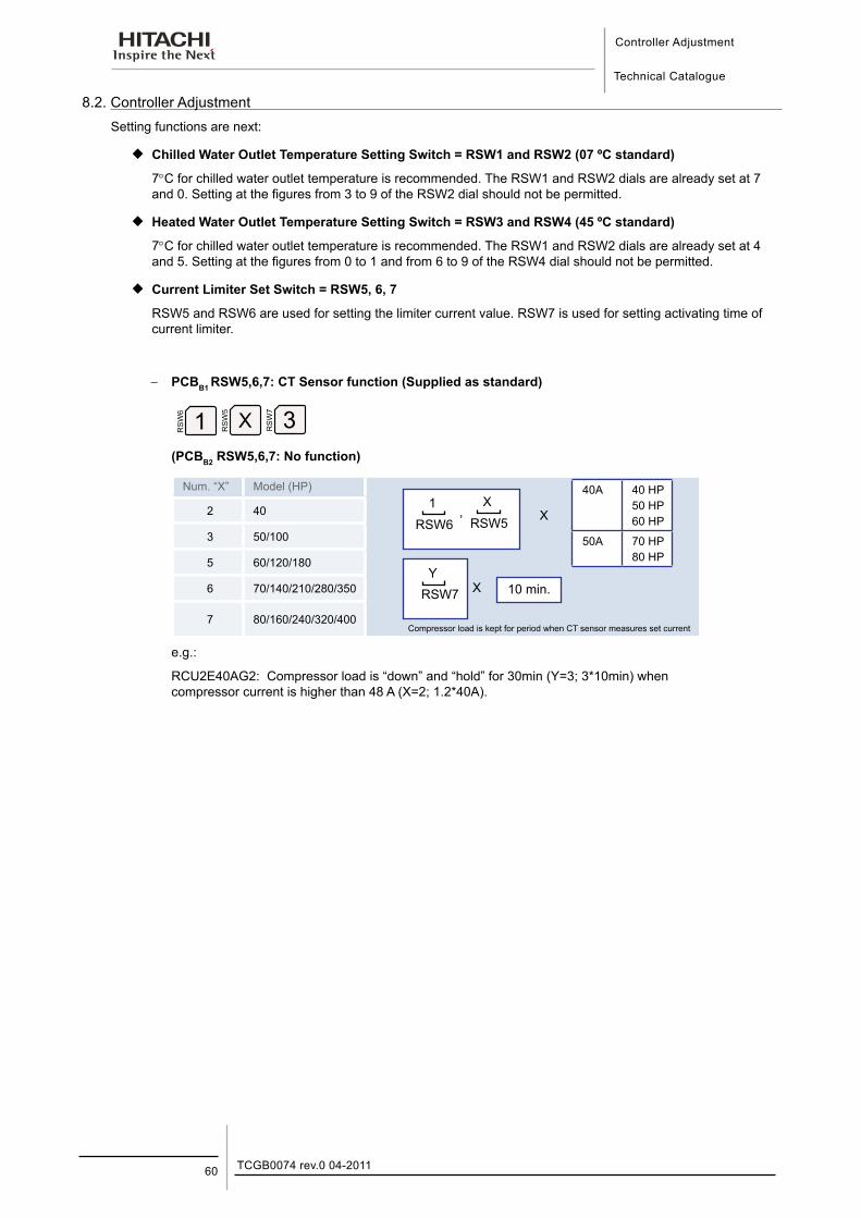
Controller Adjustment
Technical Catalogue
TCGB0074 rev.0 04-201160
8.2. Controller AdjustmentSetting functions are next:
¡ Chilled Water Outlet Temperature Setting Switch = RSW1 and RSW2 (07 ºC standard)
7°C for chilled water outlet temperature is recommended. The RSW1 and RSW2 dials are already set at 7 and 0. Setting at the figures from 3 to 9 of the RSW2 dial should not be permitted.
¡ Heated Water Outlet Temperature Setting Switch = RSW3 and RSW4 (45 ºC standard)
7°C for chilled water outlet temperature is recommended. The RSW1 and RSW2 dials are already set at 4 and 5. Setting at the figures from 0 to 1 and from 6 to 9 of the RSW4 dial should not be permitted.
¡ Current Limiter Set Switch = RSW5, 6, 7
RSW5 and RSW6 are used for setting the limiter current value. RSW7 is used for setting activating time of current limiter.
−− PCBB1 RSW5,6,7: CT Sensor function (Supplied as standard)
(PCBB2 RSW5,6,7: No function)
Num. “X” Model (HP)
Compressor load is kept for period when CT sensor measures set current
2 40
3 50/100
5 60/120/180
6 70/140/210/280/350
7 80/160/240/320/400
e.g.:
RCU2E40AG2: Compressor load is “down” and “hold” for 30min (Y=3; 3*10min) when compressor current is higher than 48 A (X=2; 1.2*40A).
YRSW7 X 10 min.
1RSW6
,X
RSW5 X
40A 40 HP50 HP60 HP
50A 70 HP80 HP
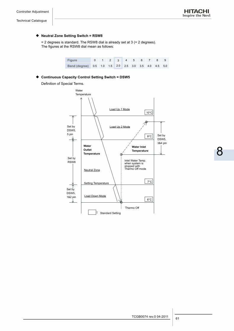
Controller Adjustment
Technical Catalogue
8
61TCGB0074 rev.0 04-2011
¡ Neutral Zone Setting Switch = RSW8
= 2 degrees is standard. The RSW8 dial is already set at 3 (= 2 degrees). The figures at the RSW8 dial mean as follows:
Figure 0 1 2 3 4 5 6 7 8 9
Band (degree) 0.5 1.0 1.5 2.0 2.5 3.0 3.5 4.0 4.5 5.0
¡ Continuous Capacity Control Setting Switch = DSW5
Definition of Special Terms.
WaterTemperature
Load Up 1 Mode10°C
Load Up 2 Mode
Set byDSW5,3&4 pin
Set byDSW5,5 pin
9°C
7°C
6°C
WaterOutletTemperature
Water InletTemperature
Set byRSW8
Set byDSW5,1&2 pin
Neutral Zone
Setting Temperature
Inlet Water Temp. when system is stopped with Thermo Off mode
Load Down Mode
Thermo Off
Standard Setting
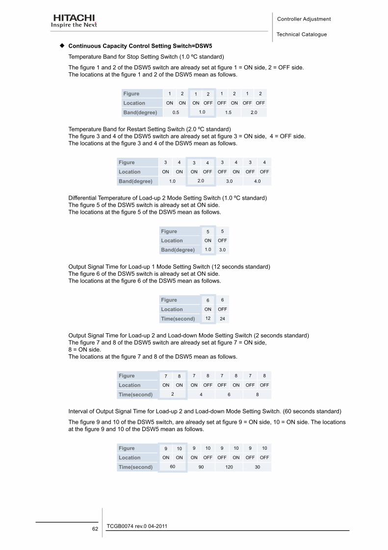
Controller Adjustment
Technical Catalogue
TCGB0074 rev.0 04-201162
¡ Continuous Capacity Control Setting Switch=DSW5
Temperature Band for Stop Setting Switch (1.0 ºC standard)
The figure 1 and 2 of the DSW5 switch are already set at figure 1 = ON side, 2 = OFF side. The locations at the figure 1 and 2 of the DSW5 mean as follows.
Figure 1 2 1 2 1 2 1 2
Location ON ON ON OFF OFF ON OFF OFF
Band(degree) 0.5 1.0 1.5 2.0
Temperature Band for Restart Setting Switch (2.0 ºC standard) The figure 3 and 4 of the DSW5 switch are already set at figure 3 = ON side, 4 = OFF side. The locations at the figure 3 and 4 of the DSW5 mean as follows.
Figure 3 4 3 4 3 4 3 4
Location ON ON ON OFF OFF ON OFF OFF
Band(degree) 1.0 2.0 3.0 4.0
Differential Temperature of Load-up 2 Mode Setting Switch (1.0 ºC standard) The figure 5 of the DSW5 switch is already set at ON side. The locations at the figure 5 of the DSW5 mean as follows.
Figure 5 5
Location ON OFF
Band(degree) 1.0 3.0
Output Signal Time for Load-up 1 Mode Setting Switch (12 seconds standard) The figure 6 of the DSW5 switch is already set at ON side. The locations at the figure 6 of the DSW5 mean as follows.
Figure 6 6
Location ON OFF
Time(second) 12 24
Output Signal Time for Load-up 2 and Load-down Mode Setting Switch (2 seconds standard) The figure 7 and 8 of the DSW5 switch are already set at figure 7 = ON side, 8 = ON side. The locations at the figure 7 and 8 of the DSW5 mean as follows.
Figure 7 8 7 8 7 8 7 8
Location ON ON ON OFF OFF ON OFF OFF
Time(second) 2 4 6 8
Interval of Output Signal Time for Load-up 2 and Load-down Mode Setting Switch. (60 seconds standard)
The figure 9 and 10 of the DSW5 switch, are already set at figure 9 = ON side, 10 = ON side. The locations at the figure 9 and 10 of the DSW5 mean as follows.
Figure 9 10 9 10 9 10 9 10
Location ON ON ON OFF OFF ON OFF OFF
Time(second) 60 90 120 30
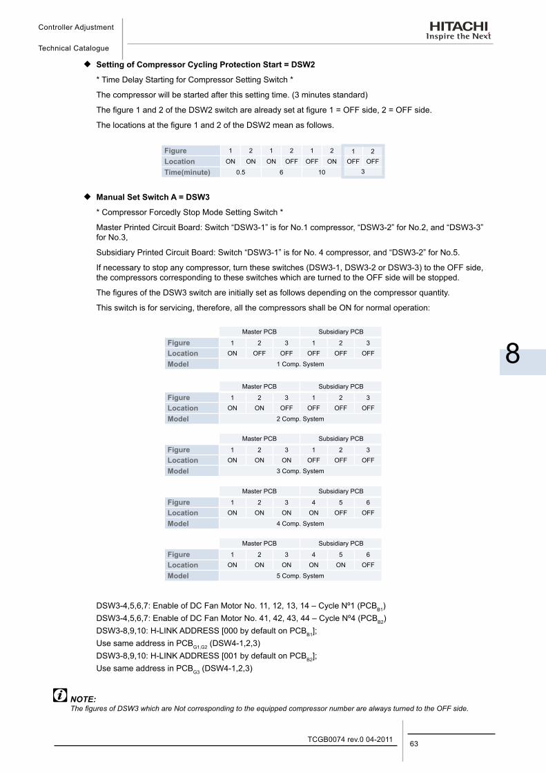
Controller Adjustment
Technical Catalogue
8
63TCGB0074 rev.0 04-2011
¡ Setting of Compressor Cycling Protection Start = DSW2
* Time Delay Starting for Compressor Setting Switch *
The compressor will be started after this setting time. (3 minutes standard)
The figure 1 and 2 of the DSW2 switch are already set at figure 1 = OFF side, 2 = OFF side.
The locations at the figure 1 and 2 of the DSW2 mean as follows.
Figure 1 2 1 2 1 2 1 2Location ON ON ON OFF OFF ON OFF OFF
Time(minute) 0.5 6 10 3
¡ Manual Set Switch A = DSW3
* Compressor Forcedly Stop Mode Setting Switch *
Master Printed Circuit Board: Switch “DSW3-1” is for No.1 compressor, “DSW3-2” for No.2, and “DSW3-3” for No.3,
Subsidiary Printed Circuit Board: Switch “DSW3-1” is for No. 4 compressor, and “DSW3-2” for No.5.
If necessary to stop any compressor, turn these switches (DSW3-1, DSW3-2 or DSW3-3) to the OFF side, the compressors corresponding to these switches which are turned to the OFF side will be stopped.
The figures of the DSW3 switch are initially set as follows depending on the compressor quantity.
This switch is for servicing, therefore, all the compressors shall be ON for normal operation:
Master PCB Subsidiary PCB
Figure 1 2 3 1 2 3Location ON OFF OFF OFF OFF OFF
Model 1 Comp. System
Master PCB Subsidiary PCB
Figure 1 2 3 1 2 3Location ON ON OFF OFF OFF OFF
Model 2 Comp. System
Master PCB Subsidiary PCB
Figure 1 2 3 1 2 3Location ON ON ON OFF OFF OFF
Model 3 Comp. System
Master PCB Subsidiary PCB
Figure 1 2 3 4 5 6Location ON ON ON ON OFF OFF
Model 4 Comp. System
Master PCB Subsidiary PCB
Figure 1 2 3 4 5 6Location ON ON ON ON ON OFF
Model 5 Comp. System
DSW3-4,5,6,7: Enable of DC Fan Motor No. 11, 12, 13, 14 – Cycle Nº1 (PCBB1)DSW3-4,5,6,7: Enable of DC Fan Motor No. 41, 42, 43, 44 – Cycle Nº4 (PCBB2)DSW3-8,9,10: H-LINK ADDRESS [000 by default on PCBB1];Use same address in PCBG1,G2 (DSW4-1,2,3)DSW3-8,9,10: H-LINK ADDRESS [001 by default on PCBB2];Use same address in PCBG3 (DSW4-1,2,3)
NOTE:The figures of DSW3 which are Not corresponding to the equipped compressor number are always turned to the OFF side.
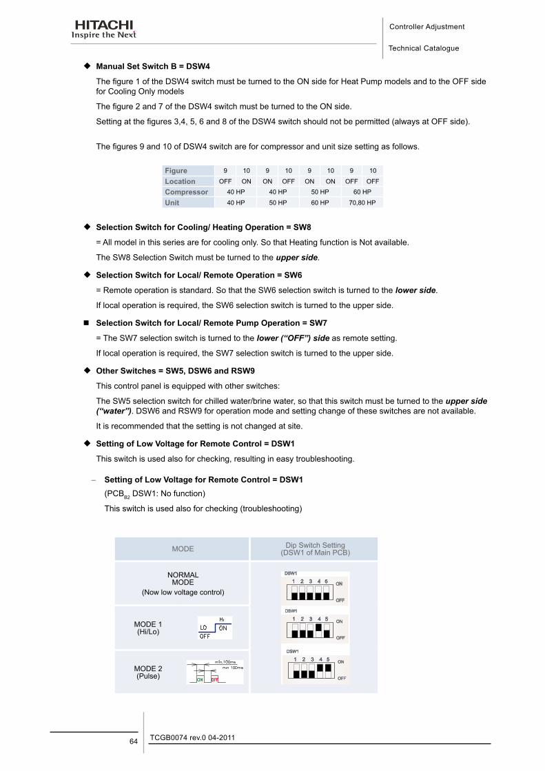
Controller Adjustment
Technical Catalogue
TCGB0074 rev.0 04-201164
¡ Manual Set Switch B = DSW4
The figure 1 of the DSW4 switch must be turned to the ON side for Heat Pump models and to the OFF side for Cooling Only models
The figure 2 and 7 of the DSW4 switch must be turned to the ON side.
Setting at the figures 3,4, 5, 6 and 8 of the DSW4 switch should not be permitted (always at OFF side).
The figures 9 and 10 of DSW4 switch are for compressor and unit size setting as follows.
Figure 9 10 9 10 9 10 9 10
Location OFF ON ON OFF ON ON OFF OFF
Compressor 40 HP 40 HP 50 HP 60 HP
Unit 40 HP 50 HP 60 HP 70,80 HP
¡ Selection Switch for Cooling/ Heating Operation = SW8
= All model in this series are for cooling only. So that Heating function is Not available.
The SW8 Selection Switch must be turned to the upper side.
¡ Selection Switch for Local/ Remote Operation = SW6
= Remote operation is standard. So that the SW6 selection switch is turned to the lower side.
If local operation is required, the SW6 selection switch is turned to the upper side.
Selection Switch for Local/ Remote Pump Operation = SW7
= The SW7 selection switch is turned to the lower (“OFF”) side as remote setting.
If local operation is required, the SW7 selection switch is turned to the upper side.
¡ Other Switches = SW5, DSW6 and RSW9
This control panel is equipped with other switches:
The SW5 selection switch for chilled water/brine water, so that this switch must be turned to the upper side (“water”). DSW6 and RSW9 for operation mode and setting change of these switches are not available.
It is recommended that the setting is not changed at site.
¡ Setting of Low Voltage for Remote Control = DSW1
This switch is used also for checking, resulting in easy troubleshooting.
−− Setting of Low Voltage for Remote Control = DSW1 (PCBB2 DSW1: No function)
This switch is used also for checking (troubleshooting)
MODE Dip Switch Setting (DSW1 of Main PCB)
NORMAL MODE
(Now low voltage control)
MODE 1 (Hi/Lo)
MODE 2 (Pulse)
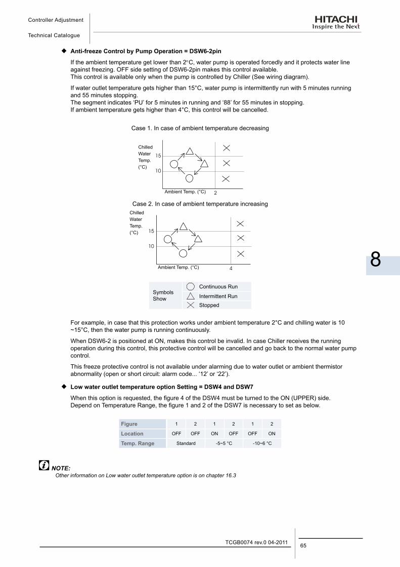
Controller Adjustment
Technical Catalogue
8
65TCGB0074 rev.0 04-2011
¡ Anti-freeze Control by Pump Operation = DSW6-2pin
If the ambient temperature get lower than 2°C, water pump is operated forcedly and it protects water line against freezing. OFF side setting of DSW6-2pin makes this control available. This control is available only when the pump is controlled by Chiller (See wiring diagram).
If water outlet temperature gets higher than 15°C, water pump is intermittently run with 5 minutes running and 55 minutes stopping. The segment indicates ‘PU’ for 5 minutes in running and ‘88’ for 55 minutes in stopping. If ambient temperature gets higher than 4°C, this control will be cancelled.
Case 1. In case of ambient temperature decreasing
Case 2. In case of ambient temperature increasing
Symbols Show
Continuous Run
Intermittent RunStopped
For example, in case that this protection works under ambient temperature 2°C and chilling water is 10 ~15°C, then the water pump is running continuously.
When DSW6-2 is positioned at ON, makes this control be invalid. In case Chiller receives the running operation during this control, this protective control will be cancelled and go back to the normal water pump control.
This freeze protective control is not available under alarming due to water outlet or ambient thermistor abnormality (open or short circuit: alarm code... ‘12’ or ‘22’).
¡ Low water outlet temperature option Setting = DSW4 and DSW7
When this option is requested, the figure 4 of the DSW4 must be turned to the ON (UPPER) side. Depend on Temperature Range, the figure 1 and 2 of the DSW7 is necessary to set as below.
Figure 1 2 1 2 1 2
Location OFF OFF ON OFF OFF ON
Temp. Range Standard -5~5 °C -10~6 °C
NOTE:Other information on Low water outlet temperature option is on chapter 16.3
ChilledWaterTemp.(°C)
Ambient Temp. (°C)
ChilledWaterTemp.(°C)
Ambient Temp. (°C)

Self-Inspection FunctionsTechnical Catalogue
9
9. S e l f - I n s p e c t i o n F u n c t i o n s
67TCGB0074 rev.0 04-2011
Contents
9. Self-Inspection functions .............................................................................................679.1. Alarm Indication ....................................................................................................................................... 68
9.2. Normal Indication..................................................................................................................................... 69
9.3. Function for indication of operation condition .......................................................................................... 70
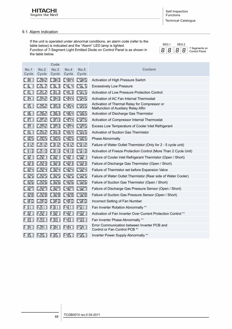
Self-Inspection Functions
Technical Catalogue
TCGB0074 rev.0 04-201168
9.1. Alarm Indication
If the unit is operated under abnormal conditions, an alarm code (refer to the table below) is indicated and the “Alarm” LED lamp is lighted. Function of 7-Segment Light Emitted Diode on Control Panel is as shown in the table below.
CodeContentNo.1
CycleNo.2Cycle
No.3Cycle
No.4Cycle
No.5Cycle
C1H1 C2H2 C3H3 C4H4 C5 H5 Activation of High Pressure Switch
C11 C22 C33 C44 C5 5 Excessively Low Pressure
C1 L1 C2 L2 C3 L3 C4 L3 C5 L5 Activation of Low Pressure Protection Control
C141 C242 C343 C444 C5 45 Activation of AC Fan Internal Thermostat
C1 51 C2 52 C3 53 C4 54 C5 55Activation of Thermal Relay for Compressor orMalfunction of Auxiliary Relay ARn
C1 61 C2 62 C3 63 C4 64 C5 65 Activation of Discharge Gas Thermistor
C171 C272 C373 C474 C5 75 Activation of Compressor Internal Thermostat
C191 C292 C393 C494 C5 95 Excess Low Temperature of Cooler Inlet Refrigerant
C1 1 C2 2 C3 3 C4 4 C5 5 Activation of Suction Gas Thermistor
C1 05 C2 05 C3 05 C4 05 C5 05 Phase Abnormally
C112 C212 C312 C412 C512 Failure of Water Outlet Thermistor (Only for 2 - 5 cycle unit)
C113 C213 C313 C413 C513 Activation of Freeze Protection Control (More Than 2 Cycle Unit)
C121 C221 C321 C421 C521 Failure of Cooler inlet Refrigerant Thermistor (Open / Short)
C123 C223 C323 C423 C523 Failure of Discharge Gas Thermistor (Open / Short)
C124 C224 C324 C424 C524 Failure of Thermistor set before Expansion Valve
C1 25 C2 25 C3 25 C4 25 C5 25 Failure of Water Outlet Thermistor (Rear side of Water Cooler)
C1 26 C2 26 C3 26 C4 26 C5 26 Failure of Suction Gas Thermistor (Open / Short)
C127 C227 C327 C427 C527 Failure of Discharge Gas Pressure Sensor (Open / Short)
C128 C228 C328 C428 C528 Failure of Suction Gas Pressure Sensor (Open / Short)
C1 F0 C2 F0 C3 F0 C4 F0 C5 F0 Incorrect Setting of Fan Number
F111 F211 F311 F411 F511 Fan Inverter Rotation Abnormally *1
F121 F221 F321 F421 F521 Activation of Fan Inverter Over Current Protection Control *1
F131 F231 F331 F431 F531 Fan Inverter Phase Abnormally *1
F141 F241 F341 F441 F541Error Communication between Inverter PCB and Control or Fan Control PCB *1
F1 51 F2 51 F3 51 F4 51 F5 51 Inverter Power Supply Abnormally *1
8 8 8 8
SEG.1 SEG.27 Segments on Control Panel
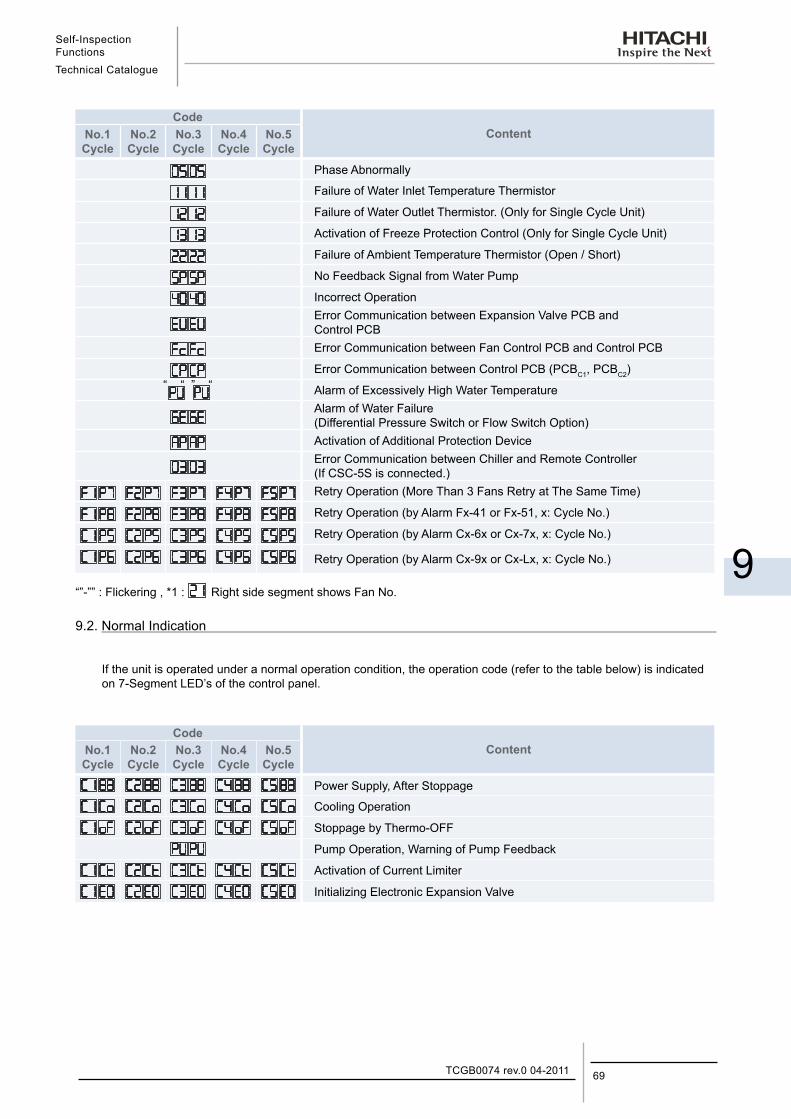
Self-Inspection FunctionsTechnical Catalogue
9
69TCGB0074 rev.0 04-2011
CodeContentNo.1
CycleNo.2Cycle
No.3Cycle
No.4Cycle
No.5Cycle
Phase Abnormally
Failure of Water Inlet Temperature Thermistor
Failure of Water Outlet Thermistor. (Only for Single Cycle Unit)
Activation of Freeze Protection Control (Only for Single Cycle Unit)
Failure of Ambient Temperature Thermistor (Open / Short)
No Feedback Signal from Water Pump
Incorrect OperationError Communication between Expansion Valve PCB and Control PCBError Communication between Fan Control PCB and Control PCB
Error Communication between Control PCB (PCBC1, PCBC2)“ “ ” “ Alarm of Excessively High Water Temperature
Alarm of Water Failure(Differential Pressure Switch or Flow Switch Option)Activation of Additional Protection DeviceError Communication between Chiller and Remote Controller (If CSC-5S is connected.)Retry Operation (More Than 3 Fans Retry at The Same Time)
Retry Operation (by Alarm Fx-41 or Fx-51, x: Cycle No.)
Retry Operation (by Alarm Cx-6x or Cx-7x, x: Cycle No.)
Retry Operation (by Alarm Cx-9x or Cx-Lx, x: Cycle No.)
“”-”” : Flickering , *1 : Right side segment shows Fan No.
9.2. Normal Indication
If the unit is operated under a normal operation condition, the operation code (refer to the table below) is indicated on 7-Segment LED’s of the control panel.
CodeContentNo.1
CycleNo.2Cycle
No.3Cycle
No.4Cycle
No.5Cycle
Power Supply, After Stoppage
Cooling Operation
Stoppage by Thermo-OFF
Pump Operation, Warning of Pump Feedback
Activation of Current Limiter
Initializing Electronic Expansion Valve
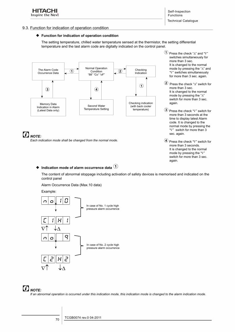
Self-Inspection Functions
Technical Catalogue
TCGB0074 rev.0 04-201170
9.3. Function for indication of operation condition
¡ Function for indication of operation condition
The setting temperature, chilled water temperature sensed at the thermistor, the setting differential temperature and the last alarm code are digitally indicated on the control panel.
The Alarm Code Occurrence Data
Normal Operation Condition
“88” “Co” “oF”
Checking Indication
Memory Data Indication in Alarm (Latest Data only)
Second Water Temperature Setting
Checking indication (with back cooler
temperature)
NOTE:Each indication mode shall be changed from the normal mode.
Press the check “∆” and “∇” switches simultaneously for more than 3 sec. It is changed to the normal mode by pressing the “∆” and “∇” switches simultaneously for more than 3 sec. again.
Press the check “∆” switch for more than 3 sec. It is changed to the normal mode by pressing the “∆” switch for more than 3 sec. again.
Press the check “∇” switch for more than 3 seconds at the time to display latest Alarm code. It is changed to the normal mode by pressing the “∇” switch for more than 3 sec. again.
Press the check “∇” switch for more than 3 seconds. It is changed to the normal mode by pressing the “∇” switch for more than 3 sec. again.
¡ Indication mode of alarm occurrence data The content of abnormal stoppage including activation of safety devices is memorised and indicated on the control panel
Alarm Occurrence Data (Max.10 data)
Example:
1 0
C 1 H 1
∇↑ ↓∆
9
C 2 H 2
∇↑− ↓∆
NOTE:If an abnormal operation is occurred under this indication mode, this indication mode is changed to the alarm indication mode.
In case of No. 1 cycle high pressure alarm occurrence
In case of No. 2 cycle high pressure alarm occurrence
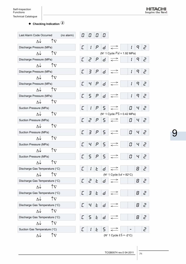
Self-Inspection FunctionsTechnical Catalogue
9
71TCGB0074 rev.0 04-2011
¡ Checking Indication
Last Alarm Code Occurred (no alarm) 0 0 0 0
∆↓ ↑∇Discharge Pressure (MPa) C 1 1 9 2
∆↓ ↑∇ (N° 1 Cycle = 1.92 MPa)
Discharge Pressure (MPa) C 2 1 9 2
∆↓ ↑∇Discharge Pressure (MPa) C 3 1 9 2
∆↓ ↑∇Discharge Pressure (MPa) C 4 1 9 2
∆↓ ↑∇Discharge Pressure (MPa) C 5 1 9 2
∆↓ ↑∇Suction Pressure (MPa) C 1 0 4 2
∆↓ ↑∇ (N° 1 Cycle = 0.42 MPa)
Suction Pressure (MPa) C 2 0 4 2
∆↓ ↑∇Suction Pressure (MPa) C 3 0 4 2
∆↓ ↑∇Suction Pressure (MPa) C 4 0 4 2
∆↓ ↑∇Suction Pressure (MPa) C 5 0 4 2
∆↓ ↑∇Discharge Gas Temperature (°C) C 1 8 2
∆↓ ↑∇ (N° 1 Cycle = 82°C)
Discharge Gas Temperature (°C) C 2 8 2
∆↓ ↑∇Discharge Gas Temperature (°C) C 3 8 2
∆↓ ↑∇Discharge Gas Temperature (°C) C 4 8 2
∆↓ ↑∇Discharge Gas Temperature (°C) C 5 8 2
∆↓ ↑∇Suction Gas Temperature (°C) C 1 2
∆↓ ↑∇ (N° 1 Cycle = -2°C)
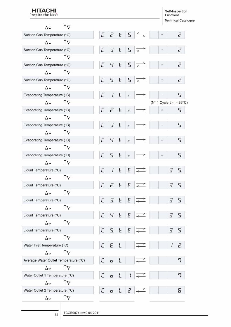
Self-Inspection Functions
Technical Catalogue
TCGB0074 rev.0 04-201172
∆↓ ↑∇Suction Gas Temperature (°C) C 2 2
∆↓ ↑∇Suction Gas Temperature (°C) C 3 2
∆↓ ↑∇Suction Gas Temperature (°C) C 4 2
∆↓ ↑∇Suction Gas Temperature (°C) C 5 2
∆↓ ↑∇Evaporating Temperature (°C) C 1 5
∆↓ ↑∇Evaporating Temperature (°C) C 2 5
∆↓ ↑∇Evaporating Temperature (°C) C 3 5
∆↓ ↑∇Evaporating Temperature (°C) C 4 5
∆↓ ↑∇Evaporating Temperature (°C) C 5 5
∆↓ ↑∇Liquid Temperature (°C) C 3 5
∆↓ ↑∇Liquid Temperature (°C) C 2 3 5
∆↓ ↑∇Liquid Temperature (°C) C 3 3 5
∆↓ ↑∇Liquid Temperature (°C) C 4 3 5
∆↓ ↑∇Liquid Temperature (°C) C 5 3 5
∆↓ ↑∇Water Inlet Temperature (°C) C L 1 2
∆↓ ↑∇Average Water Outlet Temperature (°C) C L 7
∆↓ ↑∇Water Outlet 1 Temperature (°C) C L 1 7
∆↓ ↑∇Water Outlet 2 Temperature (°C) C L 2 6
∆↓ ↑∇
(N° 1 Cycle 1 = 36°C)
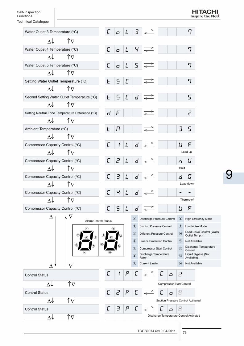
Self-Inspection FunctionsTechnical Catalogue
9
73TCGB0074 rev.0 04-2011
Water Outlet 3 Temperature (°C) C L 3 7
∆↓ ↑∇Water Outlet 4 Temperature (°C) C L 4 7
∆↓ ↑∇Water Outlet 5 Temperature (°C) C L 5 7
∆↓ ↑∇Setting Water Outlet Temperature (°C) C 7
∆↓ ↑∇Second Setting Water Outlet Temperature (°C) C 5
∆↓ ↑∇Setting Neutral Zone Temperature Difference (°C) 2
∆↓ ↑∇Ambient Temperature (°C) 3 5
∆↓ ↑∇Compressor Capacity Control (°C) C 1 L
∆↓ ↑∇Compressor Capacity Control (°C) C 2 L
∆↓ ↑∇Compressor Capacity Control (°C) C 3 L
∆↓ ↑∇Compressor Capacity Control (°C) C 4 L
∆↓ ↑∇Compressor Capacity Control (°C) C 5 L
∆ ∇
∆ ∇Control Status C C C
∆↓ ↑∇Control Status C 2 C C
∆↓ ↑∇Control Status C 3 C C
∆↓ ↑∇
Discharge Pressure Control High Efficiency Mode
Suction Pressure Control Low Noise Mode
Different Pressure Control Load Down Control (Water Outlet Temp.)
Freeze Protection Control Not Available
Compressor Start Control Discharge Temperature Control
Discharge Temperature Retry
Liquid Bypass (Not Available)
Current Limiter Not Available
8 8
Alarm Control Status
Load up
Hold
Load down
Thermo-off
Compressor Start Control
Suction Pressure Control Activated
Discharge Temperature Control Activated
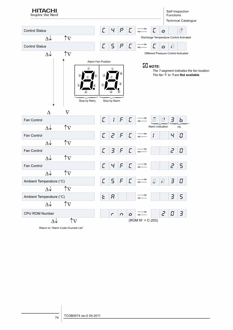
Self-Inspection Functions
Technical Catalogue
TCGB0074 rev.0 04-201174
Control Status C 4 C C
∆↓ ↑∇Control Status C 5 C C
∆↓ ↑∇
∆ ∇Fan Control C 1 C 3
∆↓ ↑∇Fan Control C 2 C 4 0
∆↓ ↑∇Fan Control C 3 C 2
∆↓ ↑∇Fan Control C 4 C 2 5
∆↓ ↑∇Ambient Temperature (°C) C 5 C 3
∆↓ ↑∇Ambient Temperature (°C) 3 5
∆↓ ↑∇CPU ROM Number 2 3
∆↓ ↑∇ (ROM N° = C-203)
NOTE:The 7-segment indicates the fan location.The fan to are Not available.
8 8
Alarm Fan Position
Return to “Alarm Code Ocurred List”
Discharge Temperature Control Activated
Different Pressure Control Activated
Stop by Retry Stop by Alarm
Alarm indication Hz
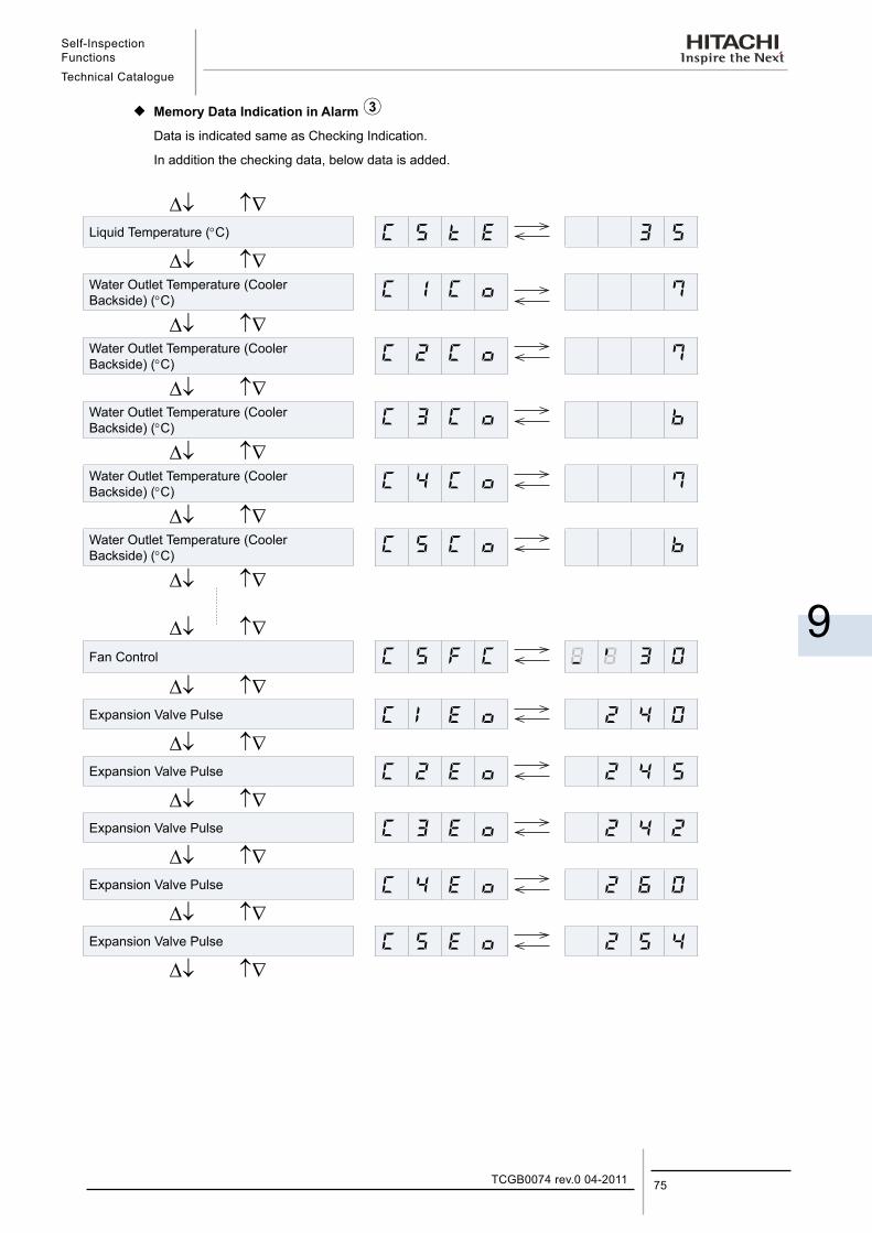
Self-Inspection FunctionsTechnical Catalogue
9
75TCGB0074 rev.0 04-2011
¡ Memory Data Indication in Alarm Data is indicated same as Checking Indication.
In addition the checking data, below data is added.
∆↓ ↑∇Liquid Temperature (°C) C 5 3 5
∆↓ ↑∇Water Outlet Temperature (Cooler Backside) (°C) C 1 C 7
∆↓ ↑∇Water Outlet Temperature (Cooler Backside) (°C) C 2 C 7
∆↓ ↑∇Water Outlet Temperature (Cooler Backside) (°C) C 3 C
∆↓ ↑∇Water Outlet Temperature (Cooler Backside) (°C) C 4 C 7
∆↓ ↑∇Water Outlet Temperature (Cooler Backside) (°C) C 5 C
∆↓ ↑∇
∆↓ ↑∇Fan Control C 5 F C 3
∆↓ ↑∇Expansion Valve Pulse C 2 4
∆↓ ↑∇Expansion Valve Pulse C 2 2 4 5
∆↓ ↑∇Expansion Valve Pulse C 3 2 4 2
∆↓ ↑∇Expansion Valve Pulse C 4 2 6
∆↓ ↑∇Expansion Valve Pulse C 5 2 5 4
∆↓ ↑∇
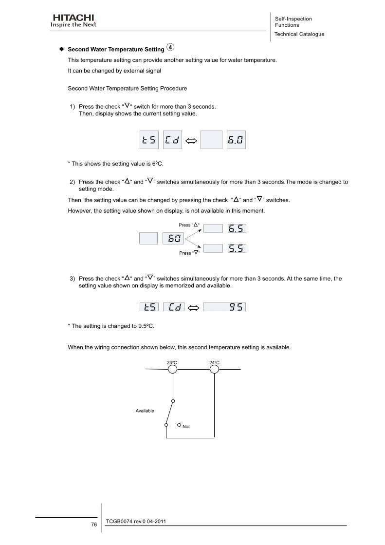
Self-Inspection Functions
Technical Catalogue
TCGB0074 rev.0 04-201176
¡ Second Water Temperature Setting This temperature setting can provide another setting value for water temperature.
It can be changed by external signal
Second Water Temperature Setting Procedure
1) Press the check “ “ switch for more than 3 seconds.Then, display shows the current setting value.
5 C ⇔ 6.
* This shows the setting value is 6ºC.
2) Press the check “
“ and “ ” switches simultaneously for more than 3 seconds.The mode is changed to setting mode.
Then, the setting value can be changed by pressing the check “
“ and “ ” switches.
However, the setting value shown on display, is not available in this moment.
6.56
5.5
3) Press the check “
“ and “ ” switches simultaneously for more than 3 seconds. At the same time, the setting value shown on display is memorized and available.
5 C ⇔ 5
* The setting is changed to 9.5ºC.
When the wiring connection shown below, this second temperature setting is available.
Press “ “
Press “
“
23ºC 24ºC
Available
Not
Control System
Technical Catalogue
10
10. C o n t r o l S y s t e m
77TCGB0074 rev.0 04-2011
Contents
10. Control System ..........................................................................................................7710.1. Standard operation sequence R(C/H)U2E40AG2, 50AG2, 60AG2, 70AG2, 80AG2 ............................ 78
10.2. Standard operation sequence R(C/H)U2E100AG2, 120AG2, 140AG2, 160AG2 ................................. 79
10.3.Standard operation sequence R(C/H)U2E180AG2, 210AG2, 240AG2 ................................................. 80
10.4. Standard Operation Sequence RCU2E280AG2, 320AG2 .................................................................... 81
10.5. Standard Operation Sequence RCU2E350AG2, 400AG2 .................................................................... 83
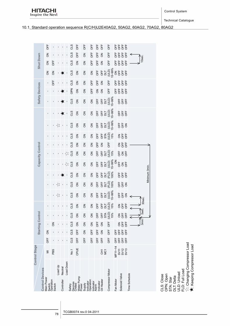
Control System
Technical Catalogue
TCGB0074 rev.0 04-201178
10.1. Standard operation sequence R(C/H)U2E40AG2, 50AG2, 60AG2, 70AG2, 80AG2
Con
trol
Sta
ge
Con
trol
Dev
ices
Star
ting
Con
trol
Cap
acity
Con
trol
Safe
ty D
evic
esSh
ut D
own
Mai
n P
ower
S
witc
hM
IO
FFO
N-
--
--
--
--
--
--
--
ON
ON
ON
OFF
Ope
ratio
n S
witc
hP
BS
--
ON
--
--
--
--
--
--
-O
FFO
NO
FF-
-
Con
trolle
rLo
ad U
p-
--
--
--
--
-
--
--
--
--
Neu
tral
--
--
--
-
--
--
-
-
--
-Lo
ad D
own
--
--
--
--
--
--
--
--
--
-S
afet
y D
evic
esN
o.1
CLS
CLS
CLS
CLS
CLS
CLS
CLS
CLS
CLS
CLS
CLS
CLS
CLS
CLS
CLS
OP
NC
LSC
LSC
LSC
LSC
LSC
hille
d W
ater
Pum
pC
PU
EO
FFO
FFO
NO
NO
NO
NO
NO
NO
NO
NO
NO
NO
NO
NO
NO
NO
NO
NO
NO
FFO
FFP
ower
S
uppl
y In
dica
tor
OFF
ON
ON
ON
ON
ON
ON
ON
ON
ON
ON
ON
ON
ON
ON
ON
ON
ON
ON
ON
OFF
Ope
ratio
n In
dica
tor
OFF
OFF
ON
ON
ON
ON
ON
ON
ON
ON
ON
ON
ON
ON
ON
OFF
OFF
ON
OFF
OFF
OFF
Ala
rm
Indi
cato
rO
FFO
FFO
FFO
FFO
FFO
FFO
FFO
FFO
FFO
FFO
FFO
FFO
FFO
FFO
FFO
NO
FFO
FFO
FFO
FFO
FF
Oil
Hea
ter
CH
1O
FFO
NO
NO
FFO
FFO
FFO
FFO
FFO
FFO
FFO
NO
FFO
FFO
FFO
FFO
NO
NO
FFO
NO
NO
FF
Com
pres
sor M
otor
MC
1S
TAD
LTD
LTD
LTD
LTD
LTD
LTS
TAD
LTD
LTD
LTD
LTO
FFO
FFO
FF(U
LD)
(ULD
)(U
LD)
(FLD
)(F
LD)
(ULD
)(U
LD)
OFF
(ULD
)(U
LD)
(ULD
)(U
LD)
OFF
OFF
(ULD
)O
FFO
FFO
FF15
%15
%15
~99%
100%
100%
15~9
9%15
%15
%15
~99%
15~9
9%15
~99%
15~9
9%Fa
n M
otor
MF1
1~14
OFF
OFF
ON
O
FFO
FFO
NO
FFO
FFO
FF
Sol
enoi
d Va
lve
SV
11O
FFO
FFO
NO
NO
NO
FFO
FFO
FFO
FFO
FFO
NO
NO
FFO
FFO
FFO
FFO
FFO
FFO
FFO
FFO
FFS
V12
OFF
OFF
OFF
OFF
OFF
OFF
OFF
OFF
ON
ON
OFF
OFF
OFF
OFF
OFF
OFF
OFF
OFF
OFF
OFF
OFF
SV
13O
FFO
FFO
FFO
FFO
FFO
NO
NO
FFO
FFO
FFO
FFO
FFO
NO
FFO
FFO
FFO
FFO
FFO
FFO
FFO
FFTi
me
Sch
edul
e
CLS
: Clo
seO
PN
: Ope
nS
TA: S
tar
DLT
: Del
taU
LD: U
nloa
dFL
D: F
ull L
oad
: C
hang
ing
Com
pres
sor L
oad
: K
eepi
ng C
ompr
esso
r Loa
d
5sec
.3m
in.
30se
c.
Min
imum
3m
in.
10se
c.
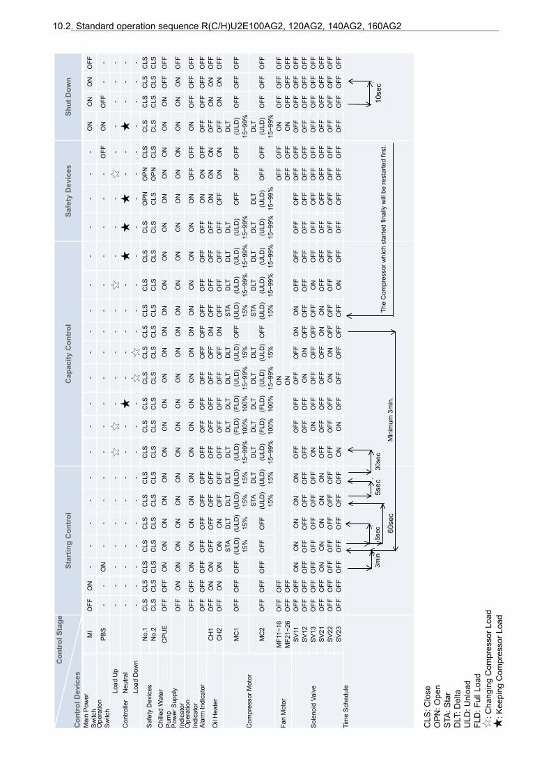
10.2. Standard operation sequence R(C/H)U2E100AG2, 120AG2, 140AG2, 160AG2
Con
trol
Sta
ge
Con
trol
Dev
ices
Star
ting
Con
trol
Cap
acity
Con
trol
Safe
ty D
evic
esSh
ut D
own
Mai
n P
ower
S
witc
hM
IO
FFO
N-
--
--
--
--
--
--
--
--
-O
NO
NO
NO
FFO
pera
tion
Sw
itch
PB
S-
-O
N-
--
--
--
--
--
--
--
-O
FFO
NO
FF-
-
Con
trolle
rLo
ad U
p-
--
--
--
--
--
-
--
-
--
--
-N
eutra
l-
--
--
--
--
-
--
--
-
-
--
-Lo
ad D
own
--
--
--
--
--
--
--
--
--
--
--
Saf
ety
Dev
ices
No.
1C
LSC
LSC
LSC
LSC
LSC
LSC
LSC
LSC
LSC
LSC
LSC
LSC
LSC
LSC
LSC
LSC
LSO
PN
OP
NC
LSC
LSC
LSC
LSC
LSN
o.2
CLS
CLS
CLS
CLS
CLS
CLS
CLS
CLS
CLS
CLS
CLS
CLS
CLS
CLS
CLS
CLS
CLS
CLS
OP
NC
LSC
LSC
LSC
LSC
LSC
hille
d W
ater
P
ump
CP
UE
OFF
OFF
ON
ON
ON
ON
ON
ON
ON
ON
ON
ON
ON
ON
ON
ON
ON
ON
ON
ON
ON
ON
OFF
OFF
Pow
er S
uppl
y In
dica
tor
OFF
ON
ON
ON
ON
ON
ON
ON
ON
ON
ON
ON
ON
ON
ON
ON
ON
ON
ON
ON
ON
ON
ON
OFF
Ope
ratio
n In
dica
tor
OFF
OFF
ON
ON
ON
ON
ON
ON
ON
ON
ON
ON
ON
ON
ON
ON
ON
ON
OFF
OFF
ON
OFF
OFF
OFF
Ala
rm In
dica
tor
OFF
OFF
OFF
OFF
OFF
OFF
OFF
OFF
OFF
OFF
OFF
OFF
OFF
OFF
OFF
OFF
OFF
ON
ON
OFF
OFF
OFF
OFF
OFF
Oil
Hea
ter
CH
1O
FFO
NO
NO
FFO
FFO
FFO
FFO
FFO
FFO
FFO
FFO
FFO
NO
FFO
FFO
FFO
FFO
NO
NO
NO
FFO
NO
NO
FFC
H2
OFF
ON
ON
ON
ON
OFF
OFF
OFF
OFF
OFF
OFF
OFF
ON
OFF
OFF
OFF
OFF
OFF
ON
ON
OFF
ON
ON
OFF
Com
pres
sor M
otor
MC
1O
FFO
FFO
FFS
TAD
LTD
LTD
LTD
LTD
LTD
LTD
LTD
LTO
FFS
TAD
LTD
LTD
LTO
FFO
FFO
FFD
LTO
FFO
FFO
FF(U
LD)
(ULD
)(U
LD)
(ULD
)(U
LD)
(FLD
)(F
LD)
(ULD
)(U
LD)
(ULD
)(U
LD)
(ULD
)(U
LD)
(ULD
)15
%15
%15
%15
%15
~99%
100%
100%
15~9
9%15
%15
%15
~99%
15~9
9%15
~99%
15~9
9%
MC
2O
FFO
FFO
FFO
FFO
FFS
TAD
LTD
LTD
LTD
LTD
LTD
LTO
FFS
TAD
LTD
LTD
LTD
LTO
FFO
FFD
LTO
FFO
FFO
FF(U
LD)
(ULD
)(U
LD)
(FLD
)(F
LD)
(ULD
)(U
LD)
(ULD
)(U
LD)
(ULD
)(U
LD)
(ULD
)(U
LD)
15%
15%
15~9
9%10
0%10
0%15
~99%
15%
15%
15~9
9%15
~99%
15~9
9%15
~99%
15~9
9%
Fan
Mot
orM
F11~
16O
FFO
FFO
N
OFF
OFF
ON
OFF
OFF
OFF
MF2
1~26
OFF
OFF
ON
O
FFO
FFO
NO
FFO
FFO
FF
Sol
enoi
d Va
lve
SV
11O
FFO
FFO
NO
NO
NO
NO
NO
FFO
FFO
FFO
FFO
FFO
NO
NO
FFO
FFO
FFO
FFO
FFO
FFO
FFO
FFO
FFO
FFS
V12
OFF
OFF
OFF
OFF
OFF
OFF
OFF
OFF
OFF
OFF
ON
ON
OFF
OFF
OFF
OFF
OFF
OFF
OFF
OFF
OFF
OFF
OFF
OFF
SV
13O
FFO
FFO
FFO
FFO
FFO
FFO
FFO
NO
NO
FFO
FFO
FFO
FFO
FFO
NO
FFO
FFO
FFO
FFO
FFO
FFO
FFO
FFO
FFS
V21
OFF
OFF
ON
ON
ON
ON
ON
OFF
OFF
OFF
OFF
OFF
ON
ON
OFF
OFF
OFF
OFF
OFF
OFF
OFF
OFF
OFF
OFF
SV
22O
FFO
FFO
FFO
FFO
FFO
FFO
FFO
FFO
FFO
FFO
NO
NO
FFO
FFO
FFO
FFO
FFO
FFO
FFO
FFO
FFO
FFO
FFO
FFS
V23
OFF
OFF
OFF
OFF
OFF
OFF
OFF
ON
ON
OFF
OFF
OFF
OFF
OFF
ON
OFF
OFF
OFF
OFF
OFF
OFF
OFF
OFF
OFF
Tim
e S
ched
ule
CLS
: Clo
seO
PN
: Ope
nS
TA: S
tar
DLT
: Del
taU
LD: U
nloa
dFL
D: F
ull L
oad
: C
hang
ing
Com
pres
sor L
oad
: K
eepi
ng C
ompr
esso
r Loa
d
..
..
.3m
in5s
ec5s
ec30
sec
Min
imum
3m
in.
10se
c60
sec
The
Com
pres
sor w
hich
sta
rted
final
ly w
ill b
e re
star
ted
first
.
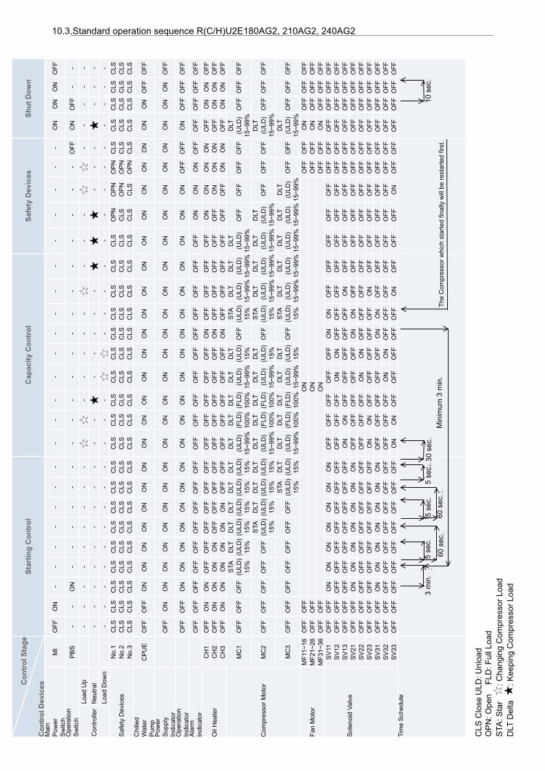
10.3.Standard operation sequence R(C/H)U2E180AG2, 210AG2, 240AG2
.
..
..
..
Con
trol
Sta
ge
Con
trol
Dev
ices
Star
ting
Con
trol
Cap
acity
Con
trol
Safe
ty D
evic
esSh
ut D
own
Mai
n P
ower
S
witc
hM
IO
FFO
N-
--
--
--
--
--
--
--
--
--
--
ON
ON
ON
OFF
Ope
ratio
n S
witc
hP
BS
--
ON
--
--
--
--
--
--
--
--
--
-O
FFO
NO
FF-
-
Con
trolle
rLo
ad U
p-
--
--
--
--
--
--
-
--
-
-
--
--
Neu
tral
--
--
--
--
--
-
--
--
-
--
-
--
-Lo
ad D
own
--
--
--
--
--
--
--
--
--
--
--
--
-
Saf
ety
Dev
ices
No.
1C
LSC
LSC
LSC
LSC
LSC
LSC
LSC
LSC
LSC
LSC
LSC
LSC
LSC
LSC
LSC
LSC
LSC
LSC
LSO
PN
OP
NO
PN
CLS
CLS
CLS
CLS
CLS
No.
2C
LSC
LSC
LSC
LSC
LSC
LSC
LSC
LSC
LSC
LSC
LSC
LSC
LSC
LSC
LSC
LSC
LSC
LSC
LSC
LSO
PN
OP
NC
LSC
LSC
LSC
LSC
LSN
o.3
CLS
CLS
CLS
CLS
CLS
CLS
CLS
CLS
CLS
CLS
CLS
CLS
CLS
CLS
CLS
CLS
CLS
CLS
CLS
CLS
CLS
OP
NC
LSC
LSC
LSC
LSC
LSC
hille
d W
ater
P
ump
CP
UE
OFF
OFF
ON
ON
ON
ON
ON
ON
ON
ON
ON
ON
ON
ON
ON
ON
ON
ON
ON
ON
ON
ON
ON
ON
ON
OFF
OFF
Pow
er
Sup
ply
Indi
cato
rO
FFO
NO
NO
NO
NO
NO
NO
NO
NO
NO
NO
NO
NO
NO
NO
NO
NO
NO
NO
NO
NO
NO
NO
NO
NO
NO
FF
Ope
ratio
n In
dica
tor
OFF
OFF
ON
ON
ON
ON
ON
ON
ON
ON
ON
ON
ON
ON
ON
ON
ON
ON
ON
ON
ON
OFF
OFF
ON
OFF
OFF
OFF
Ala
rm
Indi
cato
rO
FFO
FFO
FFO
FFO
FFO
FFO
FFO
FFO
FFO
FFO
FFO
FFO
FFO
FFO
FFO
FFO
FFO
FFO
FFO
NO
NO
NO
FFO
FFO
FFO
FFO
FF
Oil
Hea
ter
CH
1O
FFO
NO
NO
FFO
FFO
FFO
FFO
FFO
FFO
FFO
FFO
FFO
FFO
FFO
NO
FFO
FFO
FFO
FFO
NO
NO
NO
NO
FFO
NO
NO
FFC
H2
OFF
ON
ON
ON
ON
OFF
OFF
OFF
OFF
OFF
OFF
OFF
OFF
OFF
ON
OFF
OFF
OFF
OFF
OFF
ON
ON
ON
OFF
ON
ON
OFF
CH
3O
FFO
NO
NO
NO
NO
NO
NO
FFO
FFO
FFO
FFO
FFO
FFO
FFO
NO
FFO
FFO
FFO
FFO
FFO
FFO
NO
NO
FFO
NO
NO
FF
Com
pres
sor M
otor
MC
1S
TAD
LTD
LTD
LTD
LTD
LTD
LTD
LTD
LTD
LTD
LTS
TAD
LTD
LTD
LTD
LTO
FFO
FFO
FF(U
LD)
(ULD
)(U
LD)
(ULD
)(U
LD)
(ULD
)(U
LD)
(FLD
)(F
LD)
(ULD
)(U
LD)
OFF
(ULD
)(U
LD)
(ULD
)(U
LD)
OFF
OFF
OFF
OFF
(ULD
)O
FFO
FFO
FF15
%15
%15
%15
%15
%15
%15
~99%
100%
100%
15~9
9%15
%15
%15
~99%
15~9
9%15
~99%
15~9
9%
MC
2S
TAD
LTD
LTD
LTD
LTD
LTD
LTD
LTD
LTS
TAD
LTD
LTD
LTD
LTD
LTO
FFO
FFO
FFO
FFO
FF(U
LD)
(ULD
)(U
LD)
(ULD
)(U
LD)
(FLD
)(F
LD)
(ULD
)(U
LD)
OFF
(ULD
)(U
LD)
(ULD
)(U
LD)
(ULD
)O
FFO
FFO
FF(U
LD)
OFF
OFF
OFF
15%
15%
15%
15%
15~9
9%10
0%10
0%15
~99%
15%
15%
15~9
9%15
~99%
15~9
9%15
~99%
15~9
9%
MC
3S
TAD
LTD
LTD
LTD
LTD
LTD
LTS
TAD
LTD
LTD
LTD
LTD
LTD
LTO
FFO
FFO
FFO
FFO
FFO
FFO
FF(U
LD)
(ULD
)(U
LD)
(FLD
)(F
LD)
(ULD
)(U
LD)
OFF
(ULD
)(U
LD)
(ULD
)(U
LD)
(ULD
)(U
LD)
OFF
OFF
(ULD
)O
FFO
FFO
FF15
%15
%15
~99%
100%
100%
15~9
9%15
%15
%15
~99%
15~9
9%15
~99%
15~9
9%15
~99%
15~9
9%
Fan
Mot
orM
F11~
16O
FFO
FFO
N
OFF
OFF
ON
OFF
OFF
OFF
MF2
1~26
OFF
OFF
ON
O
FFO
FFO
NO
FFO
FFO
FFM
F31~
36O
FFO
FFO
N
OFF
OFF
ON
OFF
OFF
OFF
Sol
enoi
d Va
lve
SV
11O
FFO
FFO
NO
NO
NO
NO
NO
NO
NO
FFO
FFO
FFO
FFO
FFO
NO
NO
FFO
FFO
FFO
FFO
FFO
FFO
FFO
FFO
FFO
FFO
FFS
V12
OFF
OFF
OFF
OFF
OFF
OFF
OFF
OFF
OFF
OFF
OFF
OFF
ON
ON
OFF
OFF
OFF
OFF
OFF
OFF
OFF
OFF
OFF
OFF
OFF
OFF
OFF
SV
13O
FFO
FFO
FFO
FFO
FFO
FFO
FFO
FFO
FFO
NO
NO
FFO
FFO
FFO
FFO
FFO
NO
FFO
FFO
FFO
FFO
FFO
FFO
FFO
FFO
FFO
FFS
V21
OFF
OFF
ON
ON
ON
ON
ON
ON
ON
OFF
OFF
OFF
OFF
OFF
ON
ON
OFF
OFF
OFF
OFF
OFF
OFF
OFF
OFF
OFF
OFF
OFF
SV
22O
FFO
FFO
FFO
FFO
FFO
FFO
FFO
FFO
FFO
FFO
FFO
FFO
NO
NO
FFO
FFO
FFO
FFO
FFO
FFO
FFO
FFO
FFO
FFO
FFO
FFO
FFS
V23
OFF
OFF
OFF
OFF
OFF
OFF
OFF
OFF
OFF
ON
ON
OFF
OFF
OFF
OFF
OFF
ON
OFF
OFF
OFF
OFF
OFF
OFF
OFF
OFF
OFF
OFF
SV
31O
FFO
FFO
NO
NO
NO
NO
NO
NO
NO
FFO
FFO
FFO
FFO
FFO
NO
NO
FFO
FFO
FFO
FFO
FFO
FFO
FFO
FFO
FFO
FFO
FFS
V32
OFF
OFF
OFF
OFF
OFF
OFF
OFF
OFF
OFF
OFF
OFF
OFF
ON
ON
OFF
OFF
OFF
OFF
OFF
OFF
OFF
OFF
OFF
OFF
OFF
OFF
OFF
SV
33O
FFO
FFO
FFO
FFO
FFO
FFO
FFO
FFO
FFO
NO
NO
FFO
FFO
FFO
FFO
FFO
NO
FFO
FFO
FFO
NO
FFO
FFO
FFO
FFO
FFO
FFTi
me
Sch
edul
e
CLS
Clo
se U
LD: U
nloa
dO
PN
: Ope
n FL
D: F
ull L
oad
STA
: Sta
r
: Cha
ngin
g C
ompr
esso
r Loa
dD
LT D
elta
: K
eepi
ng C
ompr
esso
r Loa
d
60se
c
3min
5sec
5sec
30se
c
Min
imum
3m
in.
10se
c5s
ec 60se
c.60
sec.
3min
.5s
ec.
5sec
.30
sec.
Min
imum
3m
in.
10se
c.5s
ec.
60se
c.Th
e C
ompr
esso
r whi
ch s
tarte
d fin
ally
will
be re
star
ted
first
.
10 s
ec.
Min
imum
3 m
in.
30 s
ec.
5 se
c.3
min
.
60 s
ec.
60 s
ec.
5 se
c.5
sec.
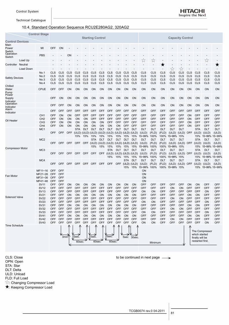
Control System
Technical Catalogue
81TCGB0074 rev.0 04-2011
10.4. Standard Operation Sequence RCU2E280AG2, 320AG2
Control Stage
Control DevicesStarting Control Capacity Control
Main Power Switch
MI OFF ON - - - - - - - - - - - - - - - - - -
Operation Switch PBS - - ON - - - - - - - - - - - - - - - - -
ControllerLoad Up - - - - - - - - - - - - - - - - -Neutral - - - - - - - - - - - - - - - - - - Load Down - - - - - - - - - - - - - - - - - -
Safety Devices
No.1 CLS CLS CLS CLS CLS CLS CLS CLS CLS CLS CLS CLS CLS CLS CLS CLS CLS CLS CLS CLSNo.2 CLS CLS CLS CLS CLS CLS CLS CLS CLS CLS CLS CLS CLS CLS CLS CLS CLS CLS CLS CLSNo.3 CLS CLS CLS CLS CLS CLS CLS CLS CLS CLS CLS CLS CLS CLS CLS CLS CLS CLS CLS CLSNo.4 CLS CLS CLS CLS CLS CLS CLS CLS CLS CLS CLS CLS CLS CLS CLS CLS CLS CLS CLS CLS
Chilled Water Pump
CPUE OFF OFF ON ON ON ON ON ON ON ON ON ON ON ON ON ON ON ON ON ON
Power Supply Indicator
OFF ON ON ON ON ON ON ON ON ON ON ON ON ON ON ON ON ON ON ON
Operation Indicator OFF OFF ON ON ON ON ON ON ON ON ON ON ON ON ON ON ON ON ON ONAlarm Indicator OFF OFF OFF OFF OFF OFF OFF OFF OFF OFF OFF OFF OFF OFF OFF OFF OFF OFF OFF OFF
Oil Heater
CH1 OFF ON ON OFF OFF OFF OFF OFF OFF OFF OFF OFF OFF OFF OFF OFF ON OFF OFF OFFCH2 OFF ON ON ON ON OFF OFF OFF OFF OFF OFF OFF OFF OFF OFF OFF ON OFF OFF OFFCH3 OFF ON ON ON ON ON ON OFF OFF OFF OFF OFF OFF OFF OFF OFF ON OFF OFF OFFCH4 OFF ON ON ON ON ON ON ON ON OFF OFF OFF OFF OFF OFF OFF ON OFF OFF OFF
Compressor Motor
MC1 STA DLT DLT DLT DLT DLT DLT DLT DLT DLT DLT DLT DLT STA DLT DLTOFF OFF OFF (ULD) (ULD) (ULD) (ULD) (ULD) (ULD) (ULD) (ULD) (ULD) (FLD) (FLD) (ULD) (ULD) OFF (ULD) (ULD) (ULD)
15% 15% 15% 15% 15% 15% 15% 15% 15~99% 100% 100% 15~99% 15% 15% 15~99% 15~99%MC2 STA DLT DLT DLT DLT DLT DLT DLT DLT DLT DLT STA DLT DLT
OFF OFF OFF OFF OFF (ULD) (ULD) (ULD) (ULD) (ULD) (ULD) (ULD) (FLD) (FLD) (ULD) (ULD) OFF (ULD) (ULD) (ULD)15% 15% 15% 15% 15% 15% 15~99% 100% 100% 15~99% 15% 15% 15~99% 15~99%
MC3 STA DLT DLT DLT DLT DLT DLT DLT DLT STA DLT DLTOFF OFF OFF OFF OFF OFF OFF (ULD) (ULD) (ULD) (ULD) (ULD) (FLD) (FLD) (ULD) (ULD) OFF (ULD) (ULD) (ULD)
15% 15% 15% 15% 15~99% 100% 100% 15~99% 15% 15% 15~99% 15~99%MC4 STA DLT DLT DLT DLT DLT DLT STA DLT DLT
OFF OFF OFF OFF OFF OFF OFF OFF OFF (ULD) (ULD) (ULD) (FLD) (FLD) (ULD) (ULD) OFF (ULD) (ULD) (ULD)15% 15% 15~99% 100% 100% 15~99% 15% 15% 15~99% 15~99%
Fan Motor
MF11~16 OFF OFF ON MF21~26 OFF OFF ON MF31~36 OFF OFF ON MF41~46 OFF OFF ON
Solenoid Valve
SV11 OFF OFF ON ON ON ON ON ON ON ON ON OFF OFF OFF OFF OFF ON ON OFF OFFSV12 OFF OFF OFF OFF OFF OFF OFF OFF OFF OFF OFF OFF OFF OFF ON ON OFF OFF OFF OFFSV13 OFF OFF OFF OFF OFF OFF OFF OFF OFF OFF OFF ON ON OFF OFF OFF OFF OFF ON OFFSV21 OFF OFF ON ON ON ON ON ON ON ON ON OFF OFF OFF OFF OFF ON ON OFF OFFSV22 OFF OFF OFF OFF OFF OFF OFF OFF OFF OFF OFF OFF OFF OFF ON ON OFF OFF OFF OFFSV23 OFF OFF OFF OFF OFF OFF OFF OFF OFF OFF OFF ON ON OFF OFF OFF OFF OFF ON OFFSV31 OFF OFF ON ON ON ON ON ON ON ON ON OFF OFF OFF OFF OFF ON ON OFF OFFSV32 OFF OFF OFF OFF OFF OFF OFF OFF OFF OFF OFF OFF OFF OFF ON ON OFF OFF OFF OFFSV33 OFF OFF OFF OFF OFF OFF OFF OFF OFF OFF OFF ON ON OFF OFF OFF OFF OFF ON OFFSV41 OFF OFF ON ON ON ON ON ON ON ON ON OFF OFF OFF OFF OFF ON ON OFF OFFSV42 OFF OFF OFF OFF OFF OFF OFF OFF OFF OFF OFF OFF OFF OFF ON ON OFF OFF OFF OFFSV43 OFF OFF OFF OFF OFF OFF OFF OFF OFF OFF OFF ON ON OFF OFF OFF OFF OFF ON OFF
Time Schedule
CLS: Close to be continued in next pageOPN: OpenSTA: StarDLT: DeltaULD: UnloadFLD: Full Load : Changing Compressor Load : Keeping Compressor Load
.
. . .
3 i
.
.
.
60sec
3min 5sec 5sec 30sec
Minimum
5sec
60sec
5sec
60sec. .
The Compressor which started finally will be restarted first.
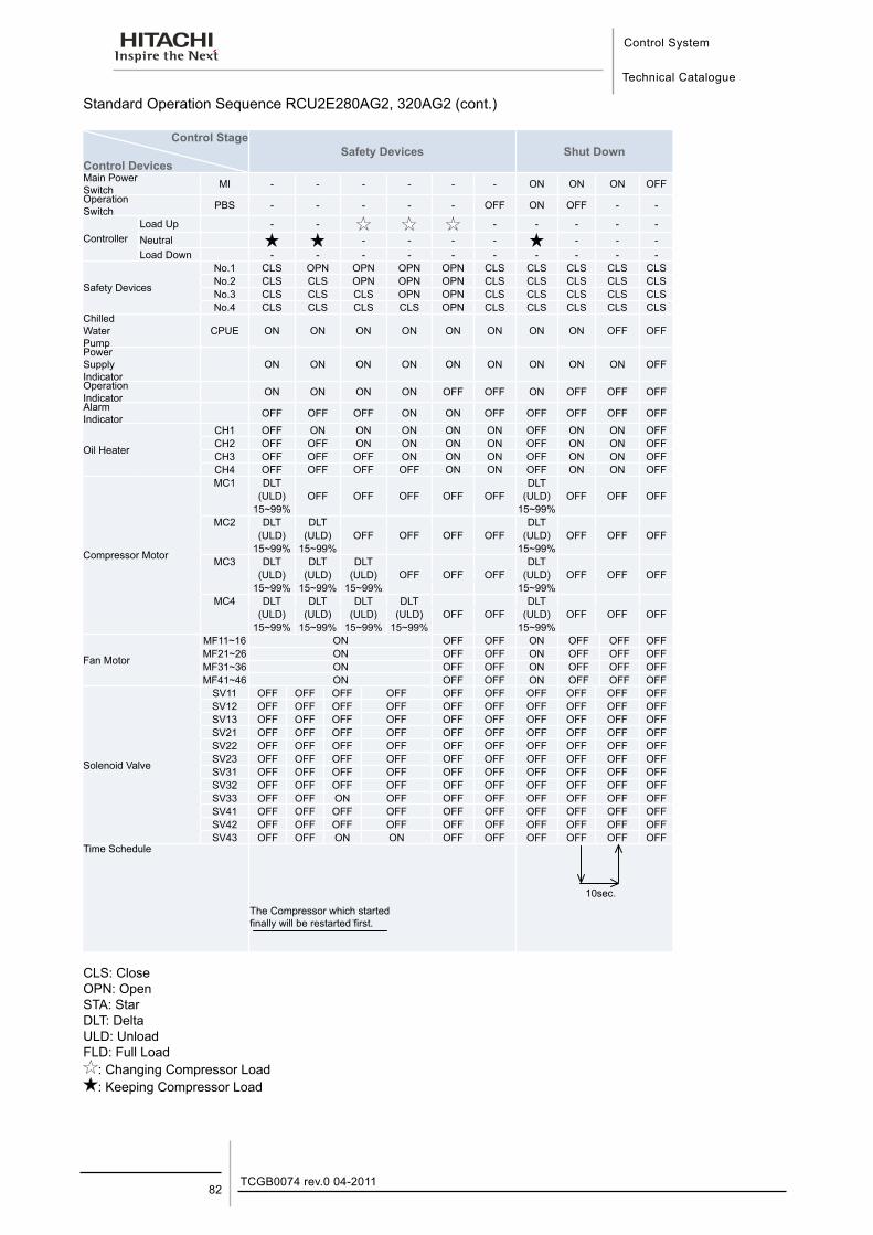
Control System
Technical Catalogue
TCGB0074 rev.0 04-201182
Standard Operation Sequence RCU2E280AG2, 320AG2 (cont.)
Control Stage
Control DevicesSafety Devices Shut Down
Main Power Switch MI - - - - - - ON ON ON OFFOperation Switch PBS - - - - - OFF ON OFF - -
ControllerLoad Up - - - - - - -Neutral - - - - - - -Load Down - - - - - - - - - -
Safety Devices
No.1 CLS OPN OPN OPN OPN CLS CLS CLS CLS CLSNo.2 CLS CLS OPN OPN OPN CLS CLS CLS CLS CLSNo.3 CLS CLS CLS OPN OPN CLS CLS CLS CLS CLSNo.4 CLS CLS CLS CLS OPN CLS CLS CLS CLS CLS
Chilled Water Pump
CPUE ON ON ON ON ON ON ON ON OFF OFF
Power Supply Indicator
ON ON ON ON ON ON ON ON ON OFF
Operation Indicator ON ON ON ON OFF OFF ON OFF OFF OFFAlarm Indicator OFF OFF OFF ON ON OFF OFF OFF OFF OFF
Oil Heater
CH1 OFF ON ON ON ON ON OFF ON ON OFFCH2 OFF OFF ON ON ON ON OFF ON ON OFFCH3 OFF OFF OFF ON ON ON OFF ON ON OFFCH4 OFF OFF OFF OFF ON ON OFF ON ON OFF
Compressor Motor
MC1 DLT DLT(ULD) OFF OFF OFF OFF OFF (ULD) OFF OFF OFF
15~99% 15~99%MC2 DLT DLT DLT
(ULD) (ULD) OFF OFF OFF OFF (ULD) OFF OFF OFF15~99% 15~99% 15~99%
MC3 DLT DLT DLT DLT(ULD) (ULD) (ULD) OFF OFF OFF (ULD) OFF OFF OFF
15~99% 15~99% 15~99% 15~99%MC4 DLT DLT DLT DLT DLT
(ULD) (ULD) (ULD) (ULD) OFF OFF (ULD) OFF OFF OFF15~99% 15~99% 15~99% 15~99% 15~99%
Fan Motor
MF11~16 ON OFF OFF ON OFF OFF OFFMF21~26 ON OFF OFF ON OFF OFF OFFMF31~36 ON OFF OFF ON OFF OFF OFFMF41~46 ON OFF OFF ON OFF OFF OFF
Solenoid Valve
SV11 OFF OFF OFF OFF OFF OFF OFF OFF OFF OFFSV12 OFF OFF OFF OFF OFF OFF OFF OFF OFF OFFSV13 OFF OFF OFF OFF OFF OFF OFF OFF OFF OFFSV21 OFF OFF OFF OFF OFF OFF OFF OFF OFF OFFSV22 OFF OFF OFF OFF OFF OFF OFF OFF OFF OFFSV23 OFF OFF OFF OFF OFF OFF OFF OFF OFF OFFSV31 OFF OFF OFF OFF OFF OFF OFF OFF OFF OFFSV32 OFF OFF OFF OFF OFF OFF OFF OFF OFF OFFSV33 OFF OFF ON OFF OFF OFF OFF OFF OFF OFFSV41 OFF OFF OFF OFF OFF OFF OFF OFF OFF OFFSV42 OFF OFF OFF OFF OFF OFF OFF OFF OFF OFFSV43 OFF OFF ON ON OFF OFF OFF OFF OFF OFF
Time Schedule
The Compressor which started finally will be restarted first.
CLS: CloseOPN: OpenSTA: StarDLT: DeltaULD: UnloadFLD: Full Load : Changing Compressor Load : Keeping Compressor Load
10sec.
.
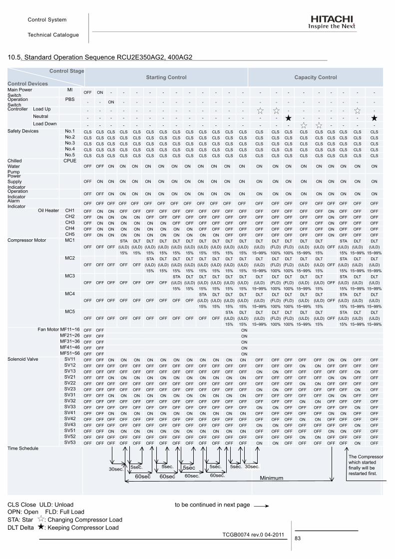
Control System
Technical Catalogue
83TCGB0074 rev.0 04-2011
10.5. Standard Operation Sequence RCU2E350AG2, 400AG2
Control Stage
Control DevicesStarting Control Capacity Control
Main Power Switch
MI OFF ON - - - - - - - - - - - - - - - - - - - -
Operation Switch
PBS - - ON - - - - - - - - - - - - - - - - - - -
Controller Load Up - - - - - - - - - - - - - - - - - - -Neutral - - - - - - - - - - - - - - - - - - - - Load Down - - - - - - - - - - - - - - - - - - - -
Safety Devices No.1 CLS CLS CLS CLS CLS CLS CLS CLS CLS CLS CLS CLS CLS CLS CLS CLS CLS CLS CLS CLS CLS CLSNo.2 CLS CLS CLS CLS CLS CLS CLS CLS CLS CLS CLS CLS CLS CLS CLS CLS CLS CLS CLS CLS CLS CLSNo.3 CLS CLS CLS CLS CLS CLS CLS CLS CLS CLS CLS CLS CLS CLS CLS CLS CLS CLS CLS CLS CLS CLSNo.4 CLS CLS CLS CLS CLS CLS CLS CLS CLS CLS CLS CLS CLS CLS CLS CLS CLS CLS CLS CLS CLS CLSNo.5 CLS CLS CLS CLS CLS CLS CLS CLS CLS CLS CLS CLS CLS CLS CLS CLS CLS CLS CLS CLS CLS CLS
Chilled Water Pump
CPUEOFF OFF ON ON ON ON ON ON ON ON ON ON ON ON ON ON ON ON ON ON ON ON
Power Supply Indicator
OFF ON ON ON ON ON ON ON ON ON ON ON ON ON ON ON ON ON ON ON ON ON
Operation Indicator OFF OFF ON ON ON ON ON ON ON ON ON ON ON ON ON ON ON ON ON ON ON ON
Alarm Indicator OFF OFF OFF OFF OFF OFF OFF OFF OFF OFF OFF OFF OFF OFF OFF OFF OFF OFF OFF OFF OFF OFF
Oil Heater CH1 OFF ON ON OFF OFF OFF OFF OFF OFF OFF OFF OFF OFF OFF OFF OFF OFF OFF ON OFF OFF OFFCH2 OFF ON ON ON ON OFF OFF OFF OFF OFF OFF OFF OFF OFF OFF OFF OFF OFF ON OFF OFF OFFCH3 OFF ON ON ON ON ON ON OFF OFF OFF OFF OFF OFF OFF OFF OFF OFF OFF ON OFF OFF OFFCH4 OFF ON ON ON ON ON ON ON ON OFF OFF OFF OFF OFF OFF OFF OFF OFF ON OFF OFF OFFCH5 OFF ON ON ON ON ON ON ON ON ON ON OFF OFF OFF OFF OFF OFF OFF ON OFF OFF OFF
Compressor Motor MC1 STA DLT DLT DLT DLT DLT DLT DLT DLT DLT DLT DLT DLT DLT DLT STA DLT DLTOFF OFF OFF (ULD) (ULD) (ULD) (ULD) (ULD) (ULD) (ULD) (ULD) (ULD) (ULD) (ULD) (FLD) (FLD) (ULD) (ULD) OFF (ULD) (ULD) (ULD)
15% 15% 15% 15% 15% 15% 15% 15% 15% 15% 15~99% 100% 100% 15~99% 15% 15% 15~99% 15~99%MC2 STA DLT DLT DLT DLT DLT DLT DLT DLT DLT DLT DLT DLT STA DLT DLT
OFF OFF OFF OFF OFF (ULD) (ULD) (ULD) (ULD) (ULD) (ULD) (ULD) (ULD) (ULD) (FLD) (FLD) (ULD) (ULD) OFF (ULD) (ULD) (ULD)15% 15% 15% 15% 15% 15% 15% 15% 15~99% 100% 100% 15~99% 15% 15% 15~99% 15~99%
MC3 STA DLT DLT DLT DLT DLT DLT DLT DLT DLT DLT STA DLT DLTOFF OFF OFF OFF OFF OFF OFF (ULD) (ULD) (ULD) (ULD) (ULD) (ULD) (ULD) (FLD) (FLD) (ULD) (ULD) OFF (ULD) (ULD) (ULD)
15% 15% 15% 15% 15% 15% 15~99% 100% 100% 15~99% 15% 15% 15~99% 15~99%MC4 STA DLT DLT DLT DLT DLT DLT DLT DLT STA DLT DLT
OFF OFF OFF OFF OFF OFF OFF OFF OFF (ULD) (ULD) (ULD) (ULD) (ULD) (FLD) (FLD) (ULD) (ULD) OFF (ULD) (ULD) (ULD)15% 15% 15% 15% 15~99% 100% 100% 15~99% 15% 15% 15~99% 15~99%
MC5 STA DLT DLT DLT DLT DLT DLT STA DLT DLTOFF OFF OFF OFF OFF OFF OFF OFF OFF OFF OFF (ULD) (ULD) (ULD) (FLD) (FLD) (ULD) (ULD) OFF (ULD) (ULD) (ULD)
15% 15% 15~99% 100% 100% 15~99% 15% 15% 15~99% 15~99%Fan Motor MF11~16 OFF OFF ON
MF21~26 OFF OFF ONMF31~36 OFF OFF ONMF41~46 OFF OFF ONMF51~56 OFF OFF ON
Solenoid Valve SV11 OFF OFF ON ON ON ON ON ON ON ON ON ON ON OFF OFF OFF OFF OFF ON ON OFF OFFSV12 OFF OFF OFF OFF OFF OFF OFF OFF OFF OFF OFF OFF OFF OFF OFF OFF ON ON OFF OFF OFF OFFSV13 OFF OFF OFF OFF OFF OFF OFF OFF OFF OFF OFF OFF OFF ON ON OFF OFF OFF OFF OFF ON OFFSV21 OFF OFF ON ON ON ON ON ON ON ON ON ON ON OFF OFF OFF OFF OFF ON ON OFF OFFSV22 OFF OFF OFF OFF OFF OFF OFF OFF OFF OFF OFF OFF OFF OFF OFF OFF ON ON OFF OFF OFF OFFSV23 OFF OFF OFF OFF OFF OFF OFF OFF OFF OFF OFF OFF OFF ON ON OFF OFF OFF OFF OFF ON OFFSV31 OFF OFF ON ON ON ON ON ON ON ON ON ON ON OFF OFF OFF OFF OFF ON ON OFF OFFSV32 OFF OFF OFF OFF OFF OFF OFF OFF OFF OFF OFF OFF OFF OFF OFF OFF ON ON OFF OFF OFF OFFSV33 OFF OFF OFF OFF OFF OFF OFF OFF OFF OFF OFF OFF OFF ON ON OFF OFF OFF OFF OFF ON OFFSV41 OFF OFF ON ON ON ON ON ON ON ON ON ON ON OFF OFF OFF OFF OFF ON ON OFF OFFSV42 OFF OFF OFF OFF OFF OFF OFF OFF OFF OFF OFF OFF OFF OFF OFF OFF ON ON OFF OFF OFF OFFSV43 OFF OFF OFF OFF OFF OFF OFF OFF OFF OFF OFF OFF OFF ON ON OFF OFF OFF OFF OFF ON OFFSV51 OFF OFF ON ON ON ON ON ON ON ON ON ON ON OFF OFF OFF OFF OFF ON ON OFF OFFSV52 OFF OFF OFF OFF OFF OFF OFF OFF OFF OFF OFF OFF OFF OFF OFF OFF ON ON OFF OFF OFF OFFSV53 OFF OFF OFF OFF OFF OFF OFF OFF OFF OFF OFF OFF OFF ON ON OFF OFF OFF OFF OFF ON OFF
Time Schedule
CLS Close ULD: Unload to be continued in next pageOPN: Open FLD: Full LoadSTA: Star : Changing Compressor LoadDLT Delta : Keeping Compressor Load
60sec.60sec60sec
5sec. 5sec.
Minimum
5sec5sec. 5sec.
60sec.
30sec.30sec.
The Compressor which started finally will be restarted first.
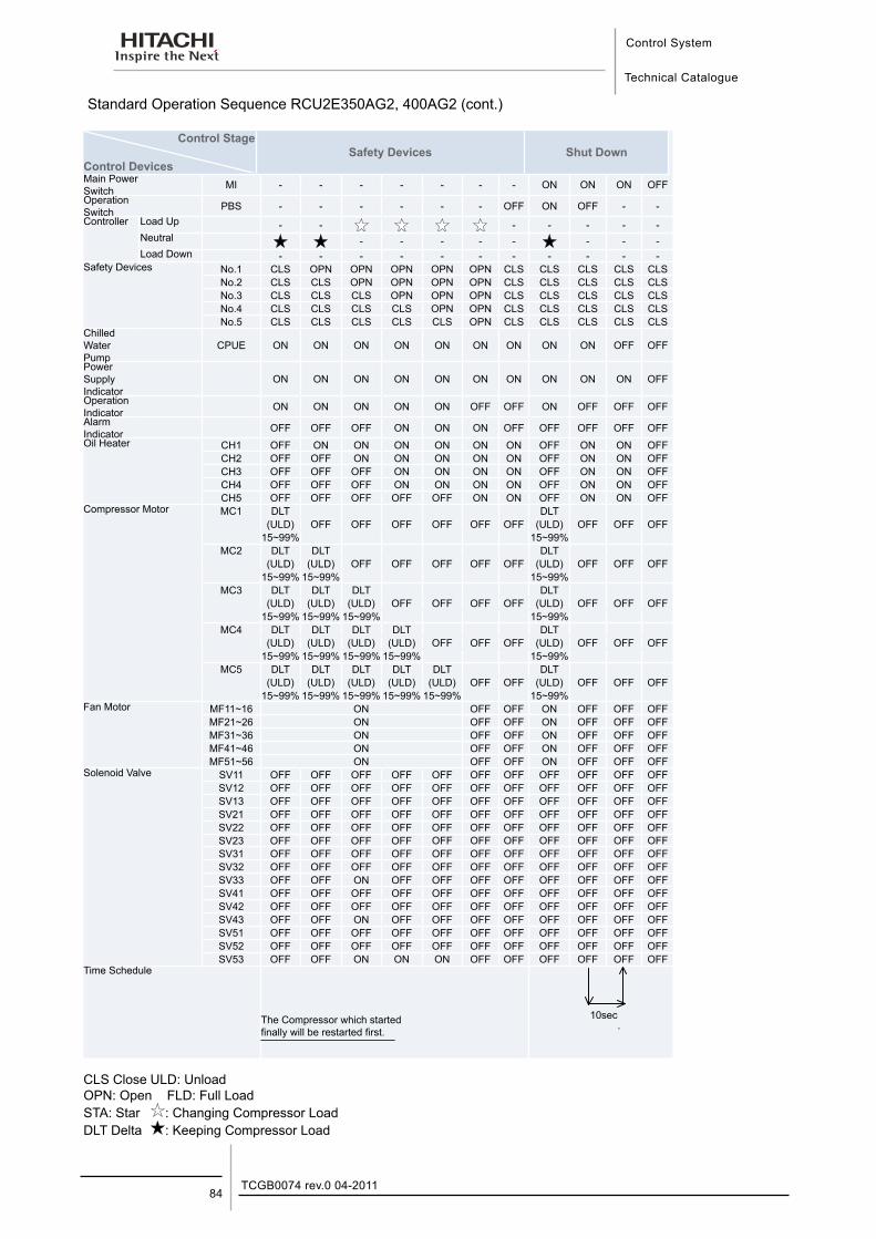
Control System
Technical Catalogue
TCGB0074 rev.0 04-201184
Standard Operation Sequence RCU2E350AG2, 400AG2 (cont.)
Control Stage
Control DevicesSafety Devices Shut Down
Main Power Switch MI - - - - - - - ON ON ON OFFOperation Switch PBS - - - - - - OFF ON OFF - -Controller Load Up - - - - - - -
Neutral - - - - - - - -Load Down - - - - - - - - - - -
Safety Devices No.1 CLS OPN OPN OPN OPN OPN CLS CLS CLS CLS CLSNo.2 CLS CLS OPN OPN OPN OPN CLS CLS CLS CLS CLSNo.3 CLS CLS CLS OPN OPN OPN CLS CLS CLS CLS CLSNo.4 CLS CLS CLS CLS OPN OPN CLS CLS CLS CLS CLSNo.5 CLS CLS CLS CLS CLS OPN CLS CLS CLS CLS CLS
Chilled Water Pump
CPUE ON ON ON ON ON ON ON ON ON OFF OFF
Power Supply Indicator
ON ON ON ON ON ON ON ON ON ON OFF
Operation Indicator ON ON ON ON ON OFF OFF ON OFF OFF OFFAlarm Indicator OFF OFF OFF ON ON ON OFF OFF OFF OFF OFFOil Heater CH1 OFF ON ON ON ON ON ON OFF ON ON OFF
CH2 OFF OFF ON ON ON ON ON OFF ON ON OFFCH3 OFF OFF OFF ON ON ON ON OFF ON ON OFFCH4 OFF OFF OFF ON ON ON ON OFF ON ON OFFCH5 OFF OFF OFF OFF OFF ON ON OFF ON ON OFF
Compressor Motor MC1 DLT DLT(ULD) OFF OFF OFF OFF OFF OFF (ULD) OFF OFF OFF
15~99% 15~99%MC2 DLT DLT DLT
(ULD) (ULD) OFF OFF OFF OFF OFF (ULD) OFF OFF OFF15~99% 15~99% 15~99%
MC3 DLT DLT DLT DLT(ULD) (ULD) (ULD) OFF OFF OFF OFF (ULD) OFF OFF OFF
15~99% 15~99% 15~99% 15~99%MC4 DLT DLT DLT DLT DLT
(ULD) (ULD) (ULD) (ULD) OFF OFF OFF (ULD) OFF OFF OFF15~99% 15~99% 15~99% 15~99% 15~99%
MC5 DLT DLT DLT DLT DLT DLT(ULD) (ULD) (ULD) (ULD) (ULD) OFF OFF (ULD) OFF OFF OFF
15~99% 15~99% 15~99% 15~99% 15~99% 15~99%Fan Motor MF11~16 ON OFF OFF ON OFF OFF OFF
MF21~26 ON OFF OFF ON OFF OFF OFFMF31~36 ON OFF OFF ON OFF OFF OFFMF41~46 ON OFF OFF ON OFF OFF OFFMF51~56 ON OFF OFF ON OFF OFF OFF
Solenoid Valve SV11 OFF OFF OFF OFF OFF OFF OFF OFF OFF OFF OFFSV12 OFF OFF OFF OFF OFF OFF OFF OFF OFF OFF OFFSV13 OFF OFF OFF OFF OFF OFF OFF OFF OFF OFF OFFSV21 OFF OFF OFF OFF OFF OFF OFF OFF OFF OFF OFFSV22 OFF OFF OFF OFF OFF OFF OFF OFF OFF OFF OFFSV23 OFF OFF OFF OFF OFF OFF OFF OFF OFF OFF OFFSV31 OFF OFF OFF OFF OFF OFF OFF OFF OFF OFF OFFSV32 OFF OFF OFF OFF OFF OFF OFF OFF OFF OFF OFFSV33 OFF OFF ON OFF OFF OFF OFF OFF OFF OFF OFFSV41 OFF OFF OFF OFF OFF OFF OFF OFF OFF OFF OFFSV42 OFF OFF OFF OFF OFF OFF OFF OFF OFF OFF OFFSV43 OFF OFF ON OFF OFF OFF OFF OFF OFF OFF OFFSV51 OFF OFF OFF OFF OFF OFF OFF OFF OFF OFF OFFSV52 OFF OFF OFF OFF OFF OFF OFF OFF OFF OFF OFFSV53 OFF OFF ON ON ON OFF OFF OFF OFF OFF OFF
Time Schedule
The Compressor which started finally will be restarted first.
CLS Close ULD: UnloadOPN: Open FLD: Full LoadSTA: Star : Changing Compressor LoadDLT Delta : Keeping Compressor Load
10sec.
Maintenance
Technical Catalogue
11
11. M a i n t e n a n c e
85TCGB0074 rev.0 04-2011
Contents
11. Maintenance ..............................................................................................................8511.1. Components .......................................................................................................................................... 86
11.2. Lubrication ............................................................................................................................................. 86
11.3. Deposit ................................................................................................................................................... 86
11.4. Cleaning Method .................................................................................................................................... 87
11.5. Winter Shutdown ................................................................................................................................... 89
11.6. Spring Start-Up ...................................................................................................................................... 89
11.7. Part Replacement .................................................................................................................................. 89
11.8. Refrigeration Cycle ................................................................................................................................ 89
11.9. Refrigerant cycle diagram of Hitachi Air-Cooled Water Chiller (RCU2E40, 50, 60, 70, 100, 120, 140, 180, 210, 280, 350AG2) ......................................................... 90
11.10. Refrigerant cycle diagram of Hitachi Air-Cooled Water Chiller (RCU2E80, 160, 240, 320, 400AG2) with economiser. ........................................................................ 91
11.11. Refrigerant cycle diagram of Hitachi Air-to-Water Heat Pump Water Chiller (RHU2E40, 50, 60, 70, 100, 120, 140, 180, 210AG2) ......................................................................... 92
11.12. Refrigerant cycle diagram of Hitachi Air-to-Water Heat Pump Water Chiller (RHU2E80, 160, 240AG2) with economiser. ........................................................................................ 93
11.13. Compressor Removal .......................................................................................................................... 94
11.14. Safety and protection control ............................................................................................................... 95
11.15. Normal operating pressure .................................................................................................................. 96
11.16. Test Running And Maintenance Record .............................................................................................. 98
11.17. Daily Operating Records ...................................................................................................................... 99
11.18. Servicing for R407C Refrigerant System ........................................................................................... 100
Maintenance
Technical Catalogue
TCGB0074 rev.0 04-201186
The unit should be periodically inspected according to the same items as those described in the paragraph titled“Test Running”. In order to ensure dependable performance and long life operation, the following additional items should be given for particular attention.
11.1. Components ¡ Compressor
The semi-hermetic screw compressor requires periodic maintenance, including replacement of parts. See the HITACHI Service Handbook for Screw Compressors, for details.
¡ Air-cooled Condenser
Inspect the condenser and remove any accumulated dirt from the coil, at regular intervals. Other obstacles such as growing grass and pieces of paper, which might restrict Air flow, should also be removed.
¡ Electrical Equipment
Always pay careful attention to working voltage, amperage and phase balance. Check for faulty contact caused by loosened terminal connections, oxidised contacts, foreign matter, and others.
¡ Control and Protective Devices
Do not readjust the settings in the field unless the setting is maintained at the point other than the point listed in the table on chapter 8.
11.2. Lubrication ¡ Compressor
The compressors are charged at the factory with the correct oil listed on the compressor nameplate. It is not necessary to add oil, if the refrigerant cycle remains sealed.
¡ Fan Motor
Bearing of all fan motors are pre-lubricated. Lubrication is not required.
11.3. DepositLime and other minerals in the chilled water tend to deposit on surfaces of plates over a long period of operation. As deposits of these minerals increase, excessive lower operation pressure is detected, indicating evidence of deposits on the water cooler.
CAUTION:Cleaning of Plate type Heat Exchangers shall be performed by specialists. Please contact your contractor o dealer of HITACHI.Clean the Water Strainer periodically according to its clogging degree.It is strongly recommended to clean the Plate Heat Exchanger at the same time the Water Strainer is cleaned.
WARNING:This product is equipped with Plate type Heat Exchangers, which are very sensitive of clogging and therefore they could get frozen unless special care is taken.For that reason it is recommended to follow accurately the next caution about normal cleaning method. For further details, please contact your HITACHI installer.
WARNING:If a fire accidentally occurs, turn OFF the main switch and use an extinguisher for an oil fire and an electric fire.Do not operate the unit near flammable gases such aslacquer, paint oil, etc. to avoid a fire or an explosion.Turn OFF the main switch when electrical box covers are removed for setting the temperature. Do not operate the unit without fixing panels.
DANGER:Switch OFF main interruptor (MI) for any work inside electrical box.Keep electrical box cover closed 2 min. after switching power off (to discharge the capacitors)
CAUTION:Perform periodical maintenance according to the “INSTRUCTIONS” to maintain the unit in a good condition.Do not touch the parts at the discharge gas side by hand, since the pipes at the discharge side are heated by refrigerant and the temperature becomes higher than 100 °C.Do not utilise this unit for cooling or heating of drinking water or food. Comply with local codes and regulations.Turn OFF all the main switches if refrigerant leakage or chilled water leakage occurs. Also, if the unit can not be stopped by the control switch, turn OFF all the switches for power source.
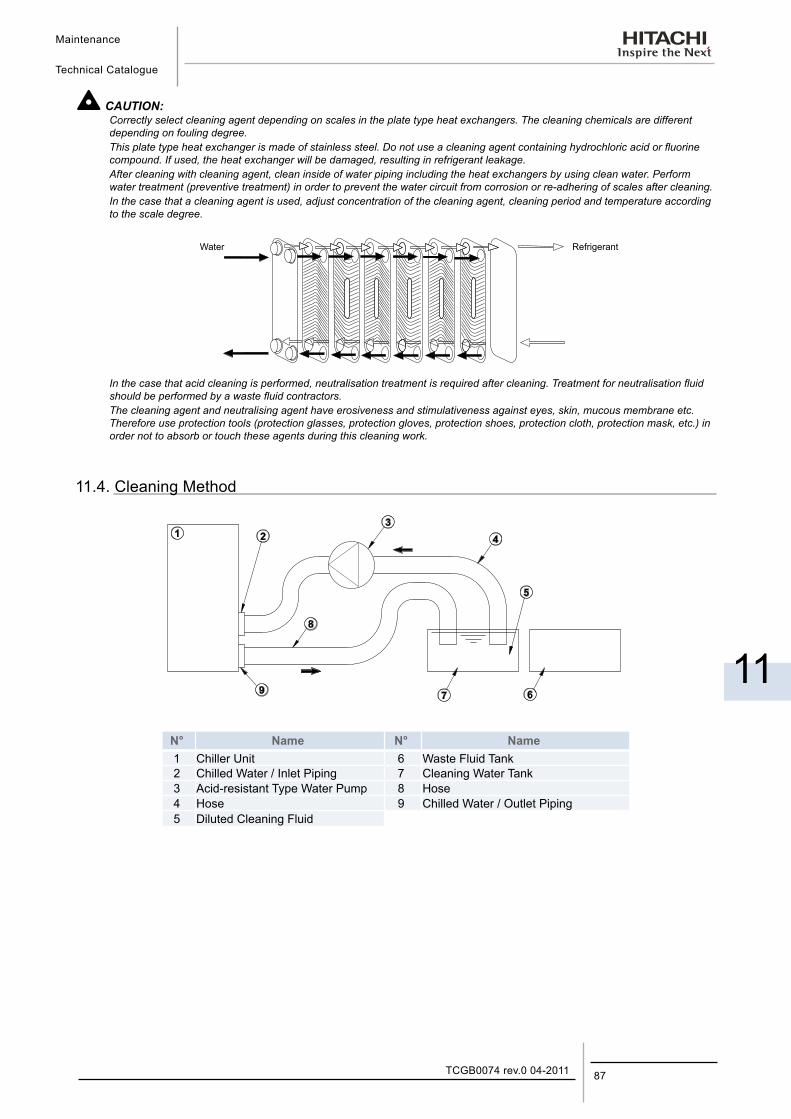
Maintenance
Technical Catalogue
11
87TCGB0074 rev.0 04-2011
CAUTION:Correctly select cleaning agent depending on scales in the plate type heat exchangers. The cleaning chemicals are different depending on fouling degree.This plate type heat exchanger is made of stainless steel. Do not use a cleaning agent containing hydrochloric acid or fluorine compound. If used, the heat exchanger will be damaged, resulting in refrigerant leakage.After cleaning with cleaning agent, clean inside of water piping including the heat exchangers by using clean water. Perform water treatment (preventive treatment) in order to prevent the water circuit from corrosion or re-adhering of scales after cleaning.In the case that a cleaning agent is used, adjust concentration of the cleaning agent, cleaning period and temperature according to the scale degree.
In the case that acid cleaning is performed, neutralisation treatment is required after cleaning. Treatment for neutralisation fluid should be performed by a waste fluid contractors.The cleaning agent and neutralising agent have erosiveness and stimulativeness against eyes, skin, mucous membrane etc. Therefore use protection tools (protection glasses, protection gloves, protection shoes, protection cloth, protection mask, etc.) in order not to absorb or touch these agents during this cleaning work.
11.4. Cleaning Method
N° Name N° Name1 Chiller Unit 6 Waste Fluid Tank2 Chilled Water / Inlet Piping 7 Cleaning Water Tank3 Acid-resistant Type Water Pump 8 Hose4 Hose 9 Chilled Water / Outlet Piping5 Diluted Cleaning Fluid
Water Refrigerant
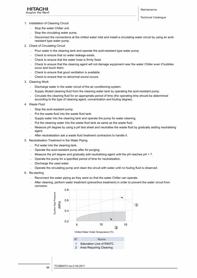
Maintenance
Technical Catalogue
TCGB0074 rev.0 04-201188
1. Installation of Cleaning Circuit
− Stop the water Chiller unit. − Stop the circulating water pump. − Disconnect the connections at the chilled water inlet and install a circulating water circuit by using an acid-
resistant type water pump.
2. Check of Circulating Circuit
− Pour water in the cleaning tank and operate the acid-resistant type water pump. − Check to ensure that no water leakage exists. − Check to ensure that the water hose is firmly fixed. − Check to ensure that the cleaning agent will not damage equipment near the water Chiller even if bubbles
occur and touch them. − Check to ensure that good ventilation is available. − Check to ensure that no abnormal sound occurs.
3. Cleaning Work
− Discharge water in the water circuit of the air conditioning system. − Supply diluted cleaning fluid from the cleaning water tank by operating the acid-resistant pump. − Circulate the cleaning fluid for an appropriate period of time (the operating time should be determined
according to the type of cleaning agent, concentration and fouling degree).
4. Waste Fluid
− Stop the acid-resistant pump. − Put the waste fluid into the waste fluid tank. − Supply water into the cleaning tank and operate the pump for water cleaning. − Put the cleaning water into the waste fluid tank as same as the waste fluid. − Measure pH degree by using a pH test sheet and neutralise the waste fluid by gradually adding neutralising
agent. − After neutralisation ask a waste fluid treatment contractors to handle it.
5. Neutralisation Treatment in the Water Piping
− Put water into the cleaning tank. − Operate the acid-resistant pump after Air-purging. − Measure the pH degree and gradually add neutralising agent until the pH reaches pH = 7. − Operate the pump for a specified period of time for neutralisation. − Discharge the used water. − Operate the circulating pump and clean the circuit with water until no fouling fluid is observed.
6. Re-starting
− Reconnect the water piping as they were so that the water Chiller can operate. − After cleaning, perform water treatment (preventive treatment) in order to prevent the water circuit from
corrosion.
N° Name1 Saturation Line of R407C2 Area Requiring Cleaning
Suc
tion
Gas
Pre
ssur
e
Chilled Water Outlet Temperature (ºC)
Maintenance
Technical Catalogue
11
89TCGB0074 rev.0 04-2011
11.5. Winter ShutdownWhen shutting down the unit for winter, clean the inside and outside of the cabinet, and dry the unit. Pump down the refrigerant to the condenser and close the liquid outlet stop valves. This unit should be covered during shutdown, in order to protect it from dust and environmental conditions. Be sure to tighten the packing glands and the cap nuts of the valves.
Remove the drain plug and drain all residual water from the water cooler piping systems, as such water may freeze during the cold season. It is very helpful to supply brine (anti-freezer) to the piping systems.
11.6. Spring Start-UpAfter any extended shutdown period, prepare the unit for operation as follows.
1. Thoroughly inspect and clean the unit.
2. Clean the water piping lines and the strainer.
Inspect the pump and other auxiliary equipment in the piping line.
3. Tighten all wiring connections and access panel.
CAUTION:When the main switch for this unit has been at the OFF position for an extended period of time, it should be switched ON at least 12 hours before start-up, so that oil in the compressor discharge casing may be warmed enough, to prevent oil foaming by the oil heater during start-up.
11.7. Part Replacement
Replacement of parts should be undertaken by ordering from the HITACHI Spare Parts List.
CAUTION:Do not replace with spare parts which are not the equivalent.
11.8. Refrigeration Cycle ¡ Strainer
Check for clogging each time when the refrigeration cycle is opened.
¡ Refrigerant Charge
Inspect the refrigerant charge of the system by checking the discharge and suction pressures. Perform a leakage test, if any leakage is suspected, and always perform such a test after a refrigeration cycle component is replaced. When refrigerant charge is required, follow the following instructions given for two cases:
1. When Refrigerant Gas Completely Leaked. Before charging the entire cycle must be completely evacuated and dehydrated. A gauge manifold or equivalent piping preparation shown in the next page is recommended as a convenient procedure regarding both charging and evacuation.
Fully open all the stop valves.
Connect the evacuation line to the check joints of the high and the low pressure sides.
Completely evacuate the entire cycle with a vacuum pump.
Charge refrigerant to the refrigeration cycle by weighing the charging cylinder. The proper refrigerant charge is listed on the nameplate.
When charging by weight is stopped due to high ambient temperature, close the valve and operate the unit after circulating the chilled water through the water cooler and installing a jumper on the low pressure switch, if required.
2. When Only Additional Refrigerant is Required. Connect a gauge manifold to check joint of low pressure side, and connect a charge cylinder to gauge manifold. Operate the unit after circulating the chilled water and install a jumper on the low pressure switch, if required. Repeat the following procedure until pressure becomes proper (refer to page 58).
Charge the gas refrigerant a little slowly into refrigeration cycle from check joint for low pressure.
Check the pressure after refrigeration cycle becomes stable.
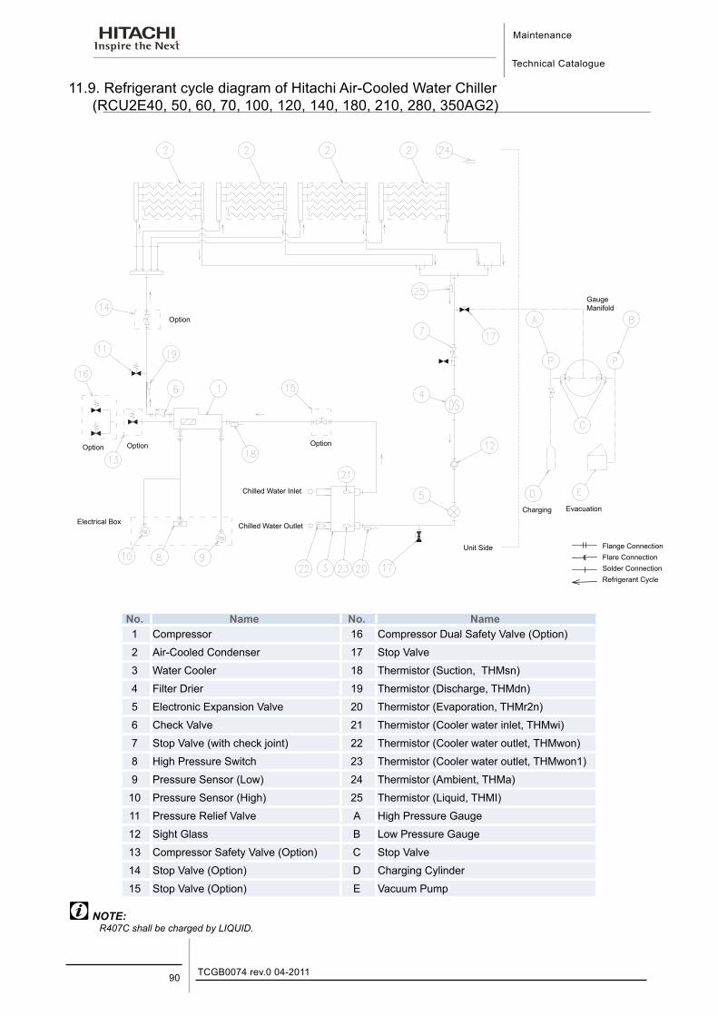
Maintenance
Technical Catalogue
TCGB0074 rev.0 04-201190
11.9. Refrigerant cycle diagram of Hitachi Air-Cooled Water Chiller (RCU2E40, 50, 60, 70, 100, 120, 140, 180, 210, 280, 350AG2)
Option
Option Option Option
Unit Side
Charging
Gauge Manifold
Flange ConnectionFlare ConnectionSolder ConnectionRefrigerant Cycle
Chilled Water Inlet
Chilled Water Outlet
Evacuation
Electrical Box
No. Name No. Name1 Compressor 16 Compressor Dual Safety Valve (Option)
2 Air-Cooled Condenser 17 Stop Valve
3 Water Cooler 18 Thermistor (Suction, THMsn)
4 Filter Drier 19 Thermistor (Discharge, THMdn)
5 Electronic Expansion Valve 20 Thermistor (Evaporation, THMr2n)
6 Check Valve 21 Thermistor (Cooler water inlet, THMwi)
7 Stop Valve (with check joint) 22 Thermistor (Cooler water outlet, THMwon)
8 High Pressure Switch 23 Thermistor (Cooler water outlet, THMwon1)
9 Pressure Sensor (Low) 24 Thermistor (Ambient, THMa)
10 Pressure Sensor (High) 25 Thermistor (Liquid, THMI)
11 Pressure Relief Valve A High Pressure Gauge
12 Sight Glass B Low Pressure Gauge
13 Compressor Safety Valve (Option) C Stop Valve
14 Stop Valve (Option) D Charging Cylinder
15 Stop Valve (Option) E Vacuum Pump
NOTE:R407C shall be charged by LIQUID.
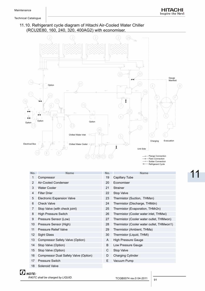
Maintenance
Technical Catalogue
11
91TCGB0074 rev.0 04-2011
11.10. Refrigerant cycle diagram of Hitachi Air-Cooled Water Chiller (RCU2E80, 160, 240, 320, 400AG2) with economiser.
Electrical Box
Option
OptionOption Option
Chilled Water Inlet
Chilled Water Outlet
Unit Side
Charging
Gauge Manifold
Evacuation
Flange ConnectionFlare ConnectionSolder ConnectionRefrigerant Cycle
No. Name No. Name1 Compressor 19 Capillary Tube
2 Air-Cooled Condenser 20 Economiser
3 Water Cooler 21 Strainer
4 Filter Drier 22 Stop Valve
5 Electronic Expansion Valve 23 Thermistor (Suction, THMsn)
6 Check Valve 24 Thermistor (Discharge, THMdn)
7 Stop Valve (with check joint) 25 Thermistor (Evaporation, THMr2n)
8 High Pressure Switch 26 Thermistor (Cooler water inlet, THMwi)
9 Pressure Sensor (Low) 27 Thermistor (Cooler water outlet, THMwon)
10 Pressure Sensor (High) 28 Thermistor (Cooler water outlet, THMwon1)
11 Pressure Relief Valve 29 Thermistor (Ambient, THMa)
12 Sight Glass 30 Thermistor (Liquid, THMI)
13 Compressor Safety Valve (Option) A High Pressure Gauge
14 Stop Valve (Option) B Low Pressure Gauge
15 Stop Valve (Option) C Stop Valve
16 Compressor Dual Safety Valve (Option) D Charging Cylinder
17 Pressure Switch E Vacuum Pump
18 Solenoid Valve
NOTE:R407C shall be charged by LIQUID.
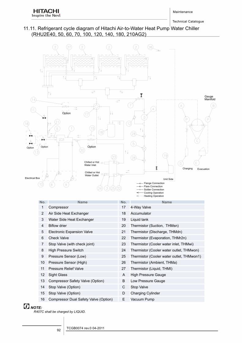
Maintenance
Technical Catalogue
TCGB0074 rev.0 04-201192
11.11. Refrigerant cycle diagram of Hitachi Air-to-Water Heat Pump Water Chiller (RHU2E40, 50, 60, 70, 100, 120, 140, 180, 210AG2)
OptionOption Option
Chilled or Hot Water Inlet
Chilled or Hot Water Outlet
Unit Side
Charging Evacuation
Electrical Box
Gauge Manifold
Flange ConnectionFlare ConnectionSolder ConnectionCooling OperationHeating Operation
Option
No. Name No. Name1 Compressor 17 4-Way Valve
2 Air Side Heat Exchanger 18 Accumulator
3 Water Side Heat Exchanger 19 Liquid tank
4 Biflow drier 20 Thermistor (Suction, THMsn)
5 Electronic Expansion Valve 21 Thermistor (Discharge, THMdn)
6 Check Valve 22 Thermistor (Evaporation, THMr2n)
7 Stop Valve (with check joint) 23 Thermistor (Cooler water inlet, THMwi)
8 High Pressure Switch 24 Thermistor (Cooler water outlet, THMwon)
9 Pressure Sensor (Low) 25 Thermistor (Cooler water outlet, THMwon1)
10 Pressure Sensor (High) 26 Thermistor (Ambient, THMa)
11 Pressure Relief Valve 27 Thermistor (Liquid, THMI)
12 Sight Glass A High Pressure Gauge
13 Compressor Safety Valve (Option) B Low Pressure Gauge
14 Stop Valve (Option) C Stop Valve
15 Stop Valve (Option) D Charging Cylinder
16 Compressor Dual Safety Valve (Option) E Vacuum Pump
NOTE:R407C shall be charged by LIQUID.
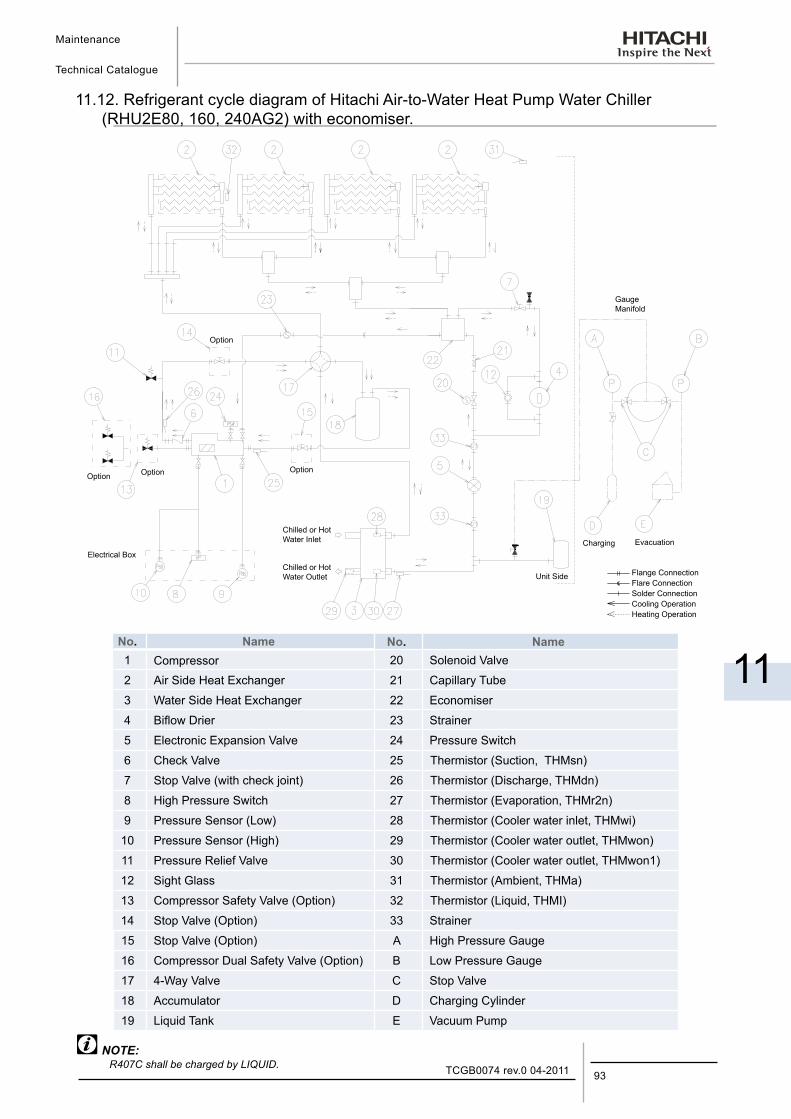
Maintenance
Technical Catalogue
11
93TCGB0074 rev.0 04-2011
11.12. Refrigerant cycle diagram of Hitachi Air-to-Water Heat Pump Water Chiller (RHU2E80, 160, 240AG2) with economiser.
OptionOption
Option
Chilled or Hot Water Inlet
Chilled or Hot Water Outlet
Option
Unit Side
Charging
Gauge Manifold
EvacuationElectrical Box
Flange ConnectionFlare ConnectionSolder ConnectionCooling OperationHeating Operation
No. Name No. Name1 Compressor 20 Solenoid Valve
2 Air Side Heat Exchanger 21 Capillary Tube
3 Water Side Heat Exchanger 22 Economiser
4 Biflow Drier 23 Strainer
5 Electronic Expansion Valve 24 Pressure Switch
6 Check Valve 25 Thermistor (Suction, THMsn)
7 Stop Valve (with check joint) 26 Thermistor (Discharge, THMdn)
8 High Pressure Switch 27 Thermistor (Evaporation, THMr2n)
9 Pressure Sensor (Low) 28 Thermistor (Cooler water inlet, THMwi)
10 Pressure Sensor (High) 29 Thermistor (Cooler water outlet, THMwon)
11 Pressure Relief Valve 30 Thermistor (Cooler water outlet, THMwon1)
12 Sight Glass 31 Thermistor (Ambient, THMa)
13 Compressor Safety Valve (Option) 32 Thermistor (Liquid, THMI)
14 Stop Valve (Option) 33 Strainer
15 Stop Valve (Option) A High Pressure Gauge
16 Compressor Dual Safety Valve (Option) B Low Pressure Gauge
17 4-Way Valve C Stop Valve
18 Accumulator D Charging Cylinder
19 Liquid Tank E Vacuum Pump
NOTE:R407C shall be charged by LIQUID.
Maintenance
Technical Catalogue
TCGB0074 rev.0 04-201194
CAUTION:Do not charge OXYGEN, ACETYLENE or other flammable and poisonous gases into the refrigeration cycle when performing a leakage test or an airtight test. These types of gases are extremely dangerous, because explosion can occur. It is recommended that compressed air or nitrogen is charged for these types of tests.Mineral deposits on water cooler plates act as thermal insulators, and also act as resistance against water flow, causing a decrease of the water flow running through them, and resulting in a decreasing of the cooling capacity. Deposits on the plates should be inspected at regular intervals. Experience with the water Chiller will dictate accurate inspection intervals. These deposits should be removed by circulating diluted acid through the water passes after the water has been drained. As water in different localities contains different minerals, different acids are required, depending upon the thickness of the deposits.This unit is equipped with an operation hour meter. In the case that the total operation time reaches 24,000 hours or 3 years pass after installation, exchange the bearings of the compressor. For details, refer to the Service Handbook for HITACHI Screw Compressors.For R407C refrigerant system, charge the refrigerant with liquid condition to avoid its composition change.
11.13. Compressor Removal
¡ When Removing the Compressor
Remove the compressor while completing the following procedures.
1. Collect all refrigerant into a condenser before this work.
2. Turn off the switch DSW3 of the PCB in the magnetic switch box in order not to operate the compressor except for the cycle.
3. Circulate the chilled water sufficiently through the water cooler, and operate the water Chiller for 10 minutes, and check to ensure that the oil level is maintained at a stable condition.
4. Stop the water Chiller and completely close the liquid stop valve.
5. Operate the water Chiller after circulating water through the water cooler.
6. Stop the water Chiller when the low pressure reaches at approximately 0.05 MPa. Do not operate at a pressure lower than 0.05 MPa. If operated, it will cause a damage to the compressor.
7. Wait for several minutes. If the low pressure increases up to 0.45 to 0.5 MPa, repeat the above procedures 5 and 6 four or five times.
8. Turn OFF the power supply to the unit.
9. After these works above, almost all refrigerant can be collected in the condenser.
10. Recover the rest of refrigerant from the water cooler and the compressor.
11. Remove the bolts on the discharge and suction flanges of the compressor.
12. Remove all the wiring of the compressor.
13. Remove the bolts fixing the compressor.
14. Remove the compressor.
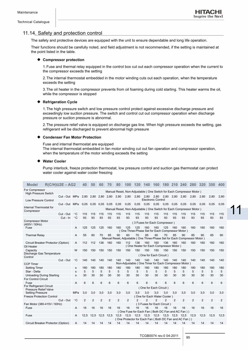
Maintenance
Technical Catalogue
11
95TCGB0074 rev.0 04-2011
11.14. Safety and protection controlThe safety and protective devices are equipped with the unit to ensure dependable and long life operation.
Their functions should be carefully noted, and field adjustment is not recommended, if the setting is maintained at the point listed in the table.
¡ Compressor protection
1. Fuse and thermal relay equipped in the control box cut out each compressor operation when the current to the compressor exceeds the setting
2. The internal thermostat embedded in the motor winding cuts out each operation, when the temperature exceeds the setting
3. The oil heater in the compressor prevents from oil foaming during cold starting. This heater warms the oil, while the compressor is stopped
¡ Refrigeration Cycle
1. The high pressure switch and low pressure control protect against excessive discharge pressure and exceedingly low suction pressure. The switch and control cut out compressor operation when discharge pressure or suction pressure is abnormal.
2. The pressure relief valve is equipped on discharge gas line. When high pressure exceeds the setting, gas refrigerant will be discharged to prevent abnormal high pressure
¡ Condenser Fan Motor Protection
Fuse and internal thermostat are equipped The internal thermostat embedded in fan motor winding cut out fan operation and compressor operation, when the temperature of the motor winding exceeds the setting
¡ Water Cooler
Pump interlock, freeze protection thermostat, low pressure control and suction gas thermostat can protect water cooler against water cooler freezing
Model R(C/H)U2E – AG2 40 50 60 70 80 100 120 140 160 180 210 240 280 320 350 400For Compressor High Pressure Switch Manual Reset, Non-Adjustable ( One Switch for Each Compressor Motor )
Cut - Out MPa 2,80 2,80 2,80 2,80 2,80 2,80 2,80 2,80 2,80 2,80 2,80 2,80 2,80 2,80 2,80 2,80 Low Pressure Control Electronic Control
Cut - Out MPa 0,05 0,05 0,05 0,05 0,05 0,05 0,05 0,05 0,05 0,05 0,05 0,05 0,05 0,05 0,05 0,05Internal Thermostat for Compressor Manual Reset, Non-Adjustable ( One Switch for Each Compressor Motor )
Cut - Out °C 115 115 115 115 115 115 115 115 115 115 115 115 115 115 115 115Cut - In °C 93 93 93 93 93 93 93 93 93 93 93 93 93 93 93 93
Compressor Motor(400V / 50Hz) ( 3 Fuses for Each Compressor )
Fuse A 125 125 125 160 160 125 125 160 160 125 160 160 160 160 160 160( One Three-Phase Set for Each Compressor Motor )
Thermal Relay A 55 60 70 85 90 60 70 85 90 70 85 90 85 90 85 90Manual Reset, Adjustable ( One Three-Phase Set for Each Compressor Motor )
Circuit Breaker Protector (Option) A 112 112 136 160 160 112 136 160 160 136 160 160 160 160 160 160Oil Heater ( One Heater for Each Compressor Motor ) Capacity W 150 150 150 150 150 150 150 150 150 150 150 150 150 150 150 150Discharge Gas TemperatureControl ( One for Each Circuit )
Cut - Out °C 140 140 140 140 140 140 140 140 140 140 140 140 140 140 140 140CCP Timer Non-Adjustable ( One Timer for Each Compressor Motor ) Setting Timer s 180 180 180 180 180 180 180 180 180 180 180 180 180 180 180 180 Star - Delta s 5 5 5 5 5 5 5 5 5 5 5 5 5 5 5 5 Unloading During Starting s 30 30 30 30 30 30 30 30 30 30 30 30 30 30 30 30For Control Circuit Fuse A 6 6 6 6 6 6 6 6 6 6 6 6 6 6 6 6For Refrigerant Circuit Pressure Relief Valve ( One for Each Circuit )
Setting Pressure MPa 3,0 3,0 3,0 3,0 3,0 3,0 3,0 3,0 3,0 3,0 3,0 3,0 3,0 3,0 3,0 3,0Freeze Protection Control ( One for Each Water Cooler )
Cut - Out °C 2 2 2 2 2 2 2 2 2 2 2 2 2 2 2 2Fan Motor (380-415V / 50Hz) ( 3 Fuses for Each Circuit ) Fuse A 16 16 16 16 16 16 16 16 16 16 16 16 16 16 16 16
( One Fuse for Each Fan ( Both DC Fan and AC Fan ) ) Fuse A 12,5 12,5 12,5 12,5 12,5 12,5 12,5 12,5 12,5 12,5 12,5 12,5 12,5 12,5 12,5 12,5
( One Protector for Each Fan ( Both DC Fan and AC Fan ) ) Circuit Breaker Protector (Option) A 14 14 14 14 14 14 14 14 14 14 14 14 14 14 14 14
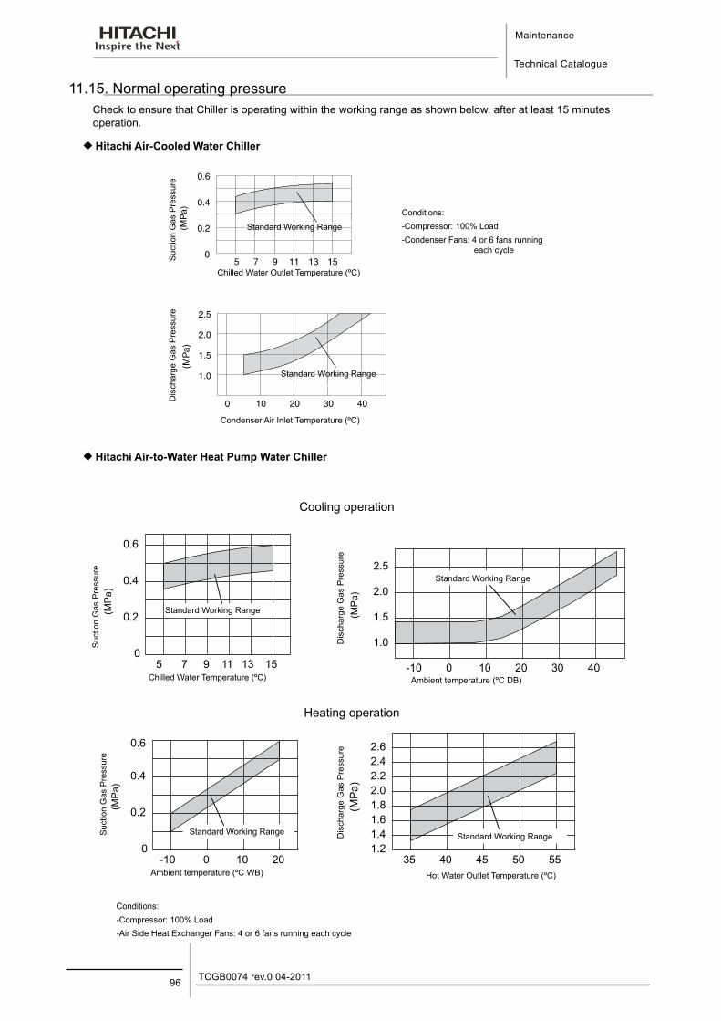
Maintenance
Technical Catalogue
TCGB0074 rev.0 04-201196
11.15. Normal operating pressureCheck to ensure that Chiller is operating within the working range as shown below, after at least 15 minutes operation.
¡Hitachi Air-Cooled Water Chiller
Standard Working Range
Chilled Water Outlet Temperature (ºC)
Condenser Air Inlet Temperature (ºC)
Suc
tion
Gas
Pre
ssur
e D
isch
arge
Gas
Pre
ssur
e
Standard Working Range
Conditions:-Compressor: 100% Load-Condenser Fans: 4 or 6 fans running
each cycle
¡Hitachi Air-to-Water Heat Pump Water Chiller
Standard Working Range
Chilled Water Temperature (ºC)
Suc
tion
Gas
Pre
ssur
e
Dis
char
ge G
as P
ress
ure
Standard Working Range
Conditions:-Compressor: 100% Load-Air Side Heat Exchanger Fans: 4 or 6 fans running each cycle
Dis
char
ge G
as P
ress
ure
Suc
tion
Gas
Pre
ssur
e
Standard Working Range Standard Working Range
Ambient temperature (ºC WB)
Ambient temperature (ºC DB)
Cooling operation
Heating operation
Hot Water Outlet Temperature (ºC)
Maintenance
Technical Catalogue
11
97TCGB0074 rev.0 04-2011
CAUTION:Periodical MaintenancePerform periodical maintenance according to the “INSTRUCTIONS” to maintain the unit in a good condition.FireIf a fire accidentally occurs, turn OFF the main switch and use an extinguisher for an oil fire and electric fire.Flammable GasesDo not operate the unit near the flammable gases such as lacquer, paint, oil, etc. to avoid a fire or an explosion.Service Panels and Electrical Box CoverTurn OFF the main switch when service panels or electrical box covers are removed for setting the temperature. Do not operate the unit without fixing panels.Heated PipeDo not touch the parts at discharge gas side by hand, since the pipes at the discharge side are heated by refrigerant and temperature becomes higher than 100ºC.UseDo not utilise this unit for cooling of drinking water or food. Comply with local codes and regulations.FailureTurn OFF all the main switches if refrigerant leakage or chilled water leakage occurs. Also, if the unit can not be stopped by the control switch, turn OFF all the switches for power source.Activation of Safety DeviceIn the case that one of safety devices is activated and unit is stopped, remove the cause of the stoppage and restart the unit. The protection devices are utilised to protect the unit from an abnormal operation. Therefore, if one of safety devices is activated, remove the cause by referring the “Troubleshooting” in the “INSTRUCTION” or call the local agency.FuseUtilise a fuse with specified capacity. Do not use a steel wire or a copper wire instead of a fuse. If an incorrect wire is utilised, a serious accident such as a fire will occur.Safety DevicesDo not make a short-circuit at the protection line. If a short-circuit is made, a serious accident will occur.Setting of Safety devicesDo not change the setting of safety devices, if changed, a serious accident will occur. Do not touch any electrical parts except for the operation switches during the operation. Do not press the button on the magnetic switch. If pressed, a serious accident will occur.
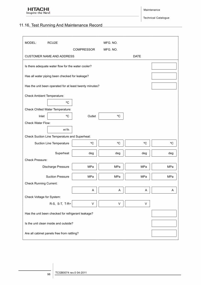
Maintenance
Technical Catalogue
TCGB0074 rev.0 04-201198
11.16. Test Running And Maintenance Record
MODEL: RCU2E MFG. NO.
COMPRESSOR MFG. NO.
CUSTOMER NAME AND ADDRESS DATE
Is there adequate water flow for the water cooler?
Has all water piping been checked for leakage?
Has the unit been operated for at least twenty minutes?
Check Ambient Temperature:
ºC
Check Chilled Water Temperature:
Inlet ºC Outlet ºC
Check Water Flow:
m3/h
Check Suction Line Temperature and Superheat:
Suction Line Temperature ºC ºC ºC ºC
Superheat deg deg deg deg
Check Pressure:
Discharge Pressure MPa MPa MPa MPa
Suction Pressure MPa MPa MPa MPa
Check Running Current:
A A A A
Check Voltage for System:
R-S, S-T, T-R= V V V
Has the unit been checked for refrigerant leakage?
Is the unit clean inside and outside?
Are all cabinet panels free from rattling?
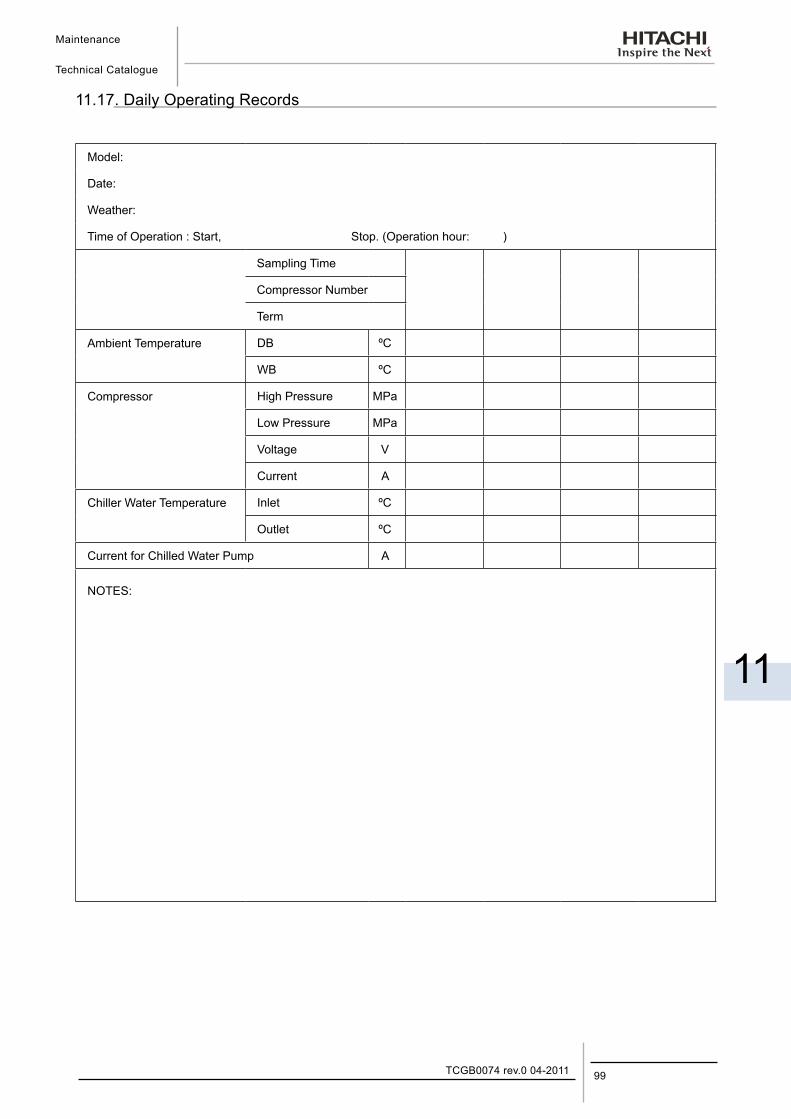
Maintenance
Technical Catalogue
11
99TCGB0074 rev.0 04-2011
11.17. Daily Operating Records
Model:
Date:
Weather:
Time of Operation : Start, Stop. (Operation hour: )
Sampling Time
Compressor Number
Term
Ambient Temperature DB ºC
WB ºC
Compressor High Pressure MPa
Low Pressure MPa
Voltage V
Current A
Chiller Water Temperature Inlet ºC
Outlet ºC
Current for Chilled Water Pump A
NOTES:
Maintenance
Technical Catalogue
TCGB0074 rev.0 04-2011100
11.18. Servicing for R407C Refrigerant System ¡ Refrigerant
This R407C refrigerant is HFC type so that it has a feature of no ozone depletion. If it is mixed with another refrigerant, the serious changing would occur on its character. Therefore notice the following point when handling this refrigerant.
1. Charge the refrigerant in LIQUID condition and NOT in GAS. As “R407C” is geotropic mixed refrigerant, if gas charging is performed, only the easy vaporising refrigerant would be charged into the system and the difficult vaporising one would be remained in the charge cylinder.
The cylinder, gauge equipped manifold and charge hose are only used for R407C refrigerant.
Adjust the cylinder setting to charge in liquid.
¡ Refrigerant Oil
UX300, which R407C refrigerant is easy to blend into it, is used for this system. The other oil is prohibited to use, so that not to be mixed with another kind of oil at the maintenance and service work. This oil is very hygroscopic.
Therefore minimum humidity handling is necessary.
¡ Servicing Equipment
When servicing R407C system, servicing equipment such as Charging Cylinder, Charging Hose, Vacuum Pump and so on, shall not be mixed with R22 equipment to avoid R407C composition change.
Troubleshooting
Technical Catalogue
12
12. Tr o u b l e s h o o t i n g
101TCGB0074 rev.0 04-2011
Contents
12. Troubleshooting .......................................................................................................10112.1.Procedures for trouble .......................................................................................................................... 102
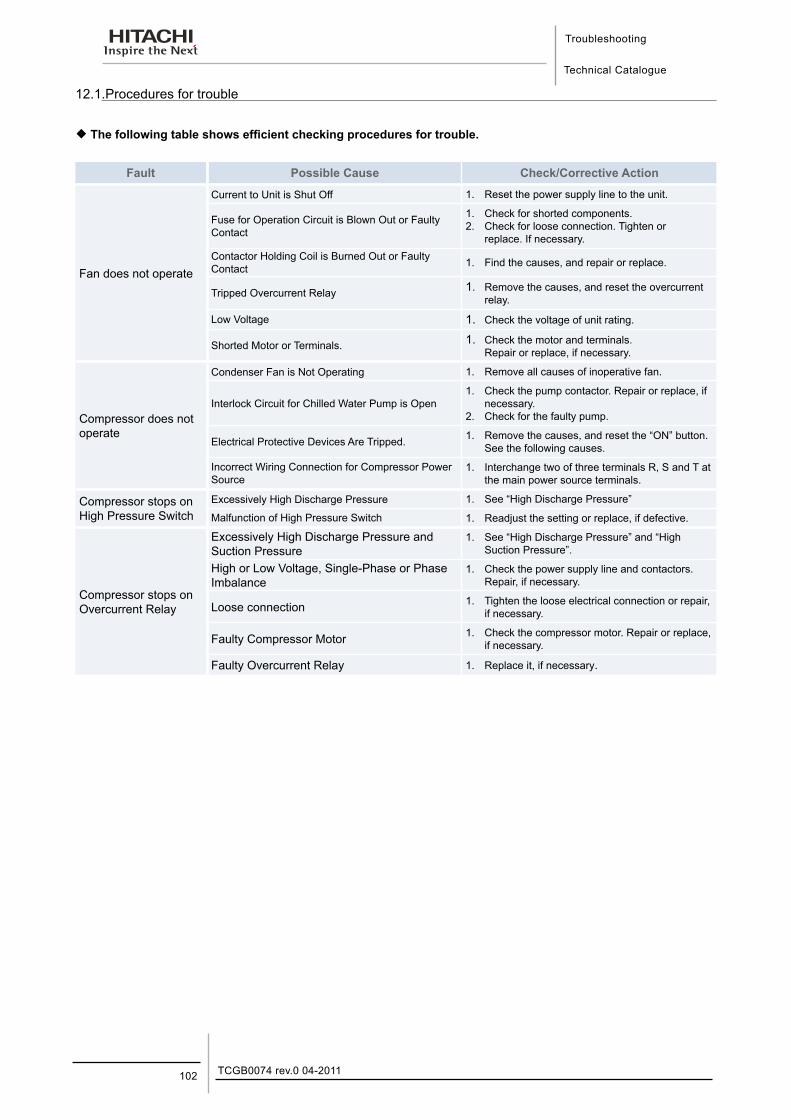
Troubleshooting
Technical Catalogue
TCGB0074 rev.0 04-2011102
12.1.Procedures for trouble
¡ The following table shows efficient checking procedures for trouble.
Fault Possible Cause Check/Corrective Action
Fan does not operate
Current to Unit is Shut Off 1. Reset the power supply line to the unit.
Fuse for Operation Circuit is Blown Out or Faulty Contact
1. Check for shorted components.2. Check for loose connection. Tighten or
replace. If necessary.Contactor Holding Coil is Burned Out or Faulty Contact 1. Find the causes, and repair or replace.
Tripped Overcurrent Relay 1. Remove the causes, and reset the overcurrent relay.
Low Voltage 1. Check the voltage of unit rating.
Shorted Motor or Terminals. 1. Check the motor and terminals.Repair or replace, if necessary.
Compressor does not operate
Condenser Fan is Not Operating 1. Remove all causes of inoperative fan.
Interlock Circuit for Chilled Water Pump is Open1. Check the pump contactor. Repair or replace, if
necessary.2. Check for the faulty pump.
Electrical Protective Devices Are Tripped. 1. Remove the causes, and reset the “ON” button. See the following causes.
Incorrect Wiring Connection for Compressor Power Source
1. Interchange two of three terminals R, S and T at the main power source terminals.
Compressor stops on High Pressure Switch
Excessively High Discharge Pressure 1. See “High Discharge Pressure”
Malfunction of High Pressure Switch 1. Readjust the setting or replace, if defective.
Compressor stops on Overcurrent Relay
Excessively High Discharge Pressure and Suction Pressure
1. See “High Discharge Pressure” and “High Suction Pressure”.
High or Low Voltage, Single-Phase or Phase Imbalance
1. Check the power supply line and contactors. Repair, if necessary.
Loose connection 1. Tighten the loose electrical connection or repair, if necessary.
Faulty Compressor Motor 1. Check the compressor motor. Repair or replace, if necessary.
Faulty Overcurrent Relay 1. Replace it, if necessary.
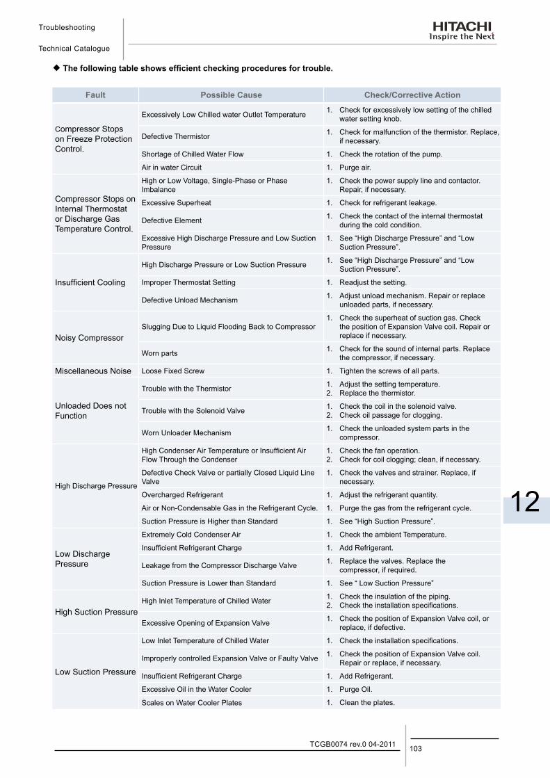
Troubleshooting
Technical Catalogue
12
103TCGB0074 rev.0 04-2011
¡ The following table shows efficient checking procedures for trouble.
Fault Possible Cause Check/Corrective Action
Compressor Stops on Freeze Protection Control.
Excessively Low Chilled water Outlet Temperature 1. Check for excessively low setting of the chilled water setting knob.
Defective Thermistor 1. Check for malfunction of the thermistor. Replace, if necessary.
Shortage of Chilled Water Flow 1. Check the rotation of the pump.
Air in water Circuit 1. Purge air.
Compressor Stops on Internal Thermostat or Discharge Gas Temperature Control.
High or Low Voltage, Single-Phase or Phase Imbalance
1. Check the power supply line and contactor. Repair, if necessary.
Excessive Superheat 1. Check for refrigerant leakage.
Defective Element 1. Check the contact of the internal thermostat during the cold condition.
Excessive High Discharge Pressure and Low Suction Pressure
1. See “High Discharge Pressure” and “Low Suction Pressure”.
Insufficient Cooling
High Discharge Pressure or Low Suction Pressure 1. See “High Discharge Pressure” and “Low Suction Pressure”.
Improper Thermostat Setting 1. Readjust the setting.
Defective Unload Mechanism 1. Adjust unload mechanism. Repair or replace unloaded parts, if necessary.
Noisy CompressorSlugging Due to Liquid Flooding Back to Compressor
1. Check the superheat of suction gas. Check the position of Expansion Valve coil. Repair or replace if necessary.
Worn parts 1. Check for the sound of internal parts. Replace the compressor, if necessary.
Miscellaneous Noise Loose Fixed Screw 1. Tighten the screws of all parts.
Unloaded Does not Function
Trouble with the Thermistor 1. Adjust the setting temperature.2. Replace the thermistor.
Trouble with the Solenoid Valve 1. Check the coil in the solenoid valve.2. Check oil passage for clogging.
Worn Unloader Mechanism 1. Check the unloaded system parts in the compressor.
High Discharge Pressure
High Condenser Air Temperature or Insufficient Air Flow Through the Condenser
1. Check the fan operation.2. Check for coil clogging; clean, if necessary.
Defective Check Valve or partially Closed Liquid Line Valve
1. Check the valves and strainer. Replace, if necessary.
Overcharged Refrigerant 1. Adjust the refrigerant quantity.
Air or Non-Condensable Gas in the Refrigerant Cycle. 1. Purge the gas from the refrigerant cycle.
Suction Pressure is Higher than Standard 1. See “High Suction Pressure”.
Low Discharge Pressure
Extremely Cold Condenser Air 1. Check the ambient Temperature.
Insufficient Refrigerant Charge 1. Add Refrigerant.
Leakage from the Compressor Discharge Valve 1. Replace the valves. Replace the compressor, if required.
Suction Pressure is Lower than Standard 1. See “ Low Suction Pressure”
High Suction PressureHigh Inlet Temperature of Chilled Water 1. Check the insulation of the piping.
2. Check the installation specifications.
Excessive Opening of Expansion Valve 1. Check the position of Expansion Valve coil, or replace, if defective.
Low Suction Pressure
Low Inlet Temperature of Chilled Water 1. Check the installation specifications.
Improperly controlled Expansion Valve or Faulty Valve 1. Check the position of Expansion Valve coil. Repair or replace, if necessary.
Insufficient Refrigerant Charge 1. Add Refrigerant.
Excessive Oil in the Water Cooler 1. Purge Oil.
Scales on Water Cooler Plates 1. Clean the plates.

General SpecificationsTechnical Catalogue
13
13. G e n e r a l S p e c i f i c a t i o n s
105TCGB0074 rev.0 04-2011
Contents
13. General specifications .............................................................................................10513.1. General Data ....................................................................................................................................... 106
13.2. Options line up......................................................................................................................................113
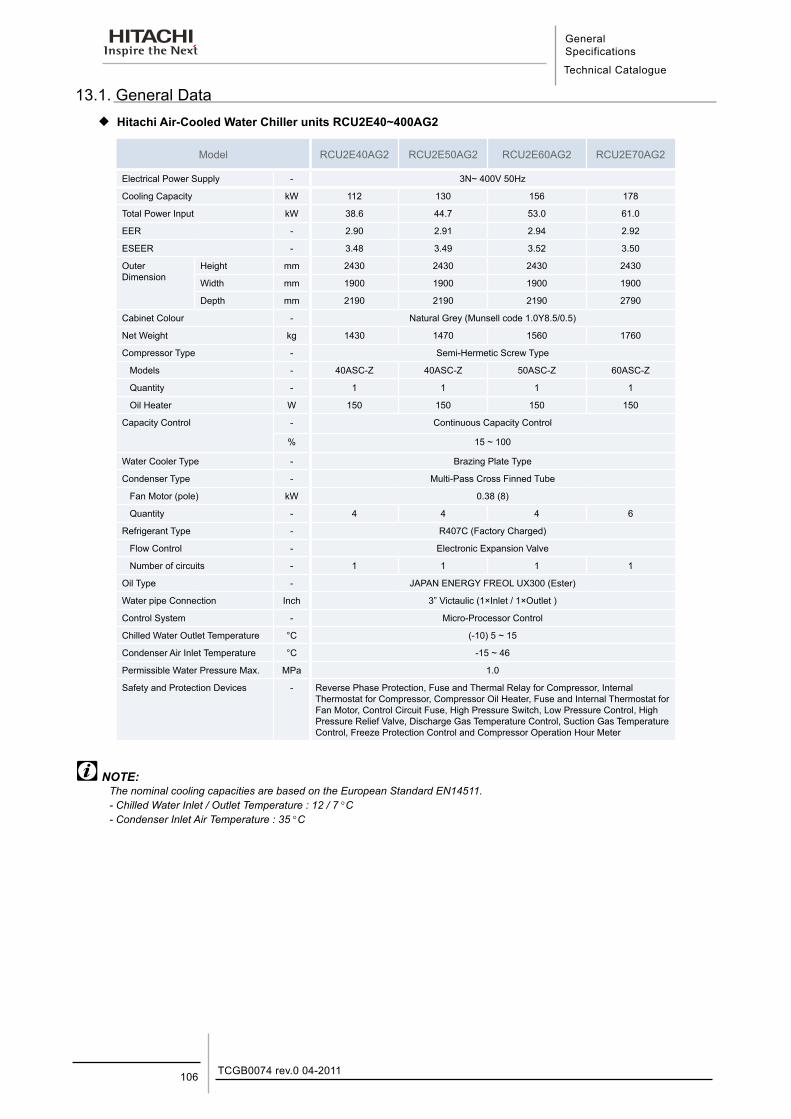
General Specifications
Technical Catalogue
TCGB0074 rev.0 04-2011106
13.1. General Data ¡ Hitachi Air-Cooled Water Chiller units RCU2E40~400AG2
Model RCU2E40AG2 RCU2E50AG2 RCU2E60AG2 RCU2E70AG2
Electrical Power Supply - 3N~ 400V 50Hz
Cooling Capacity kW 112 130 156 178
Total Power Input kW 38.6 44.7 53.0 61.0
EER - 2.90 2.91 2.94 2.92
ESEER - 3.48 3.49 3.52 3.50
Outer Dimension
Height mm 2430 2430 2430 2430
Width mm 1900 1900 1900 1900
Depth mm 2190 2190 2190 2790
Cabinet Colour - Natural Grey (Munsell code 1.0Y8.5/0.5)
Net Weight kg 1430 1470 1560 1760
Compressor Type - Semi-Hermetic Screw Type
Models - 40ASC-Z 40ASC-Z 50ASC-Z 60ASC-Z
Quantity - 1 1 1 1
Oil Heater W 150 150 150 150
Capacity Control - Continuous Capacity Control
% 15 ~ 100
Water Cooler Type - Brazing Plate Type
Condenser Type - Multi-Pass Cross Finned Tube
Fan Motor (pole) kW 0.38 (8)
Quantity - 4 4 4 6
Refrigerant Type - R407C (Factory Charged)
Flow Control - Electronic Expansion Valve
Number of circuits - 1 1 1 1
Oil Type - JAPAN ENERGY FREOL UX300 (Ester)
Water pipe Connection Inch 3” Victaulic (1×Inlet / 1×Outlet )
Control System - Micro-Processor Control
Chilled Water Outlet Temperature °C (-10) 5 ~ 15
Condenser Air Inlet Temperature °C -15 ~ 46
Permissible Water Pressure Max. MPa 1.0
Safety and Protection Devices - Reverse Phase Protection, Fuse and Thermal Relay for Compressor, Internal Thermostat for Compressor, Compressor Oil Heater, Fuse and Internal Thermostat for Fan Motor, Control Circuit Fuse, High Pressure Switch, Low Pressure Control, High Pressure Relief Valve, Discharge Gas Temperature Control, Suction Gas Temperature Control, Freeze Protection Control and Compressor Operation Hour Meter
NOTE:The nominal cooling capacities are based on the European Standard EN14511.- Chilled Water Inlet / Outlet Temperature : 12 / 7 °C- Condenser Inlet Air Temperature : 35 °C
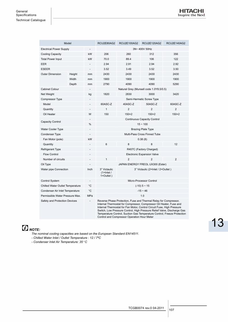
General SpecificationsTechnical Catalogue
13
107TCGB0074 rev.0 04-2011
Model RCU2E80AG2 RCU2E100AG2 RCU2E120AG2 RCU2E140AG2
Electrical Power Supply - 3N~ 400V 50Hz
Cooling Capacity kW 206 260 312 356
Total Power Input kW 70.0 89.4 106 122
EER - 2.94 2.91 2.94 2.92
ESEER - 3.52 3.49 3.52 3.50
Outer Dimension Height mm 2430 2430 2430 2430
Width mm 1900 1900 1900 1900
Depth mm 2790 4090 4090 5290
Cabinet Colour - Natural Grey (Munsell code 1.0Y8.5/0.5)
Net Weight kg 1820 2830 3000 3420
Compressor Type - Semi-Hermetic Screw Type
Model - 60ASC-Z 40ASC-Z 50ASC-Z 60ASC-Z
Quantity - 1 2 2 2
Oil Heater W 150 150×2 150×2 150×2
Capacity Control- Continuous Capacity Control
% 15 ~ 100
Water Cooler Type - Brazing Plate Type
Condenser Type - Multi-Pass Cross Finned Tube
Fan Motor (pole) kW 0.38 (8)
Quantity - 6 8 8 12
Refrigerant Type - R407C (Factory Charged)
Flow Control - Electronic Expansion Valve
Number of circuits - 1 2 2 2
Oil Type - JAPAN ENERGY FREOL UX300 (Ester)
Water pipe Connection Inch 3” Victaulic (1×Inlet / 1×Outlet )
3” Victaulic (2×Inlet / 2×Outlet )
Control System - Micro-Processor Control
Chilled Water Outlet Temperature °C (-10) 5 ~ 15
Condenser Air Inlet Temperature °C -15 ~ 46
Permissible Water Pressure Max. MPa 1.0
Safety and Protection Devices - Reverse Phase Protection, Fuse and Thermal Relay for Compressor, Internal Thermostat for Compressor, Compressor Oil Heater, Fuse and Internal Thermostat for Fan Motor, Control Circuit Fuse, High Pressure Switch, Low Pressure Control, High Pressure Relief Valve, Discharge Gas Temperature Control, Suction Gas Temperature Control, Freeze Protection Control and Compressor Operation Hour Meter
NOTE:The nominal cooling capacities are based on the European Standard EN14511.- Chilled Water Inlet / Outlet Temperature : 12 / 7ºC - Condenser Inlet Air Temperature: 35 °C
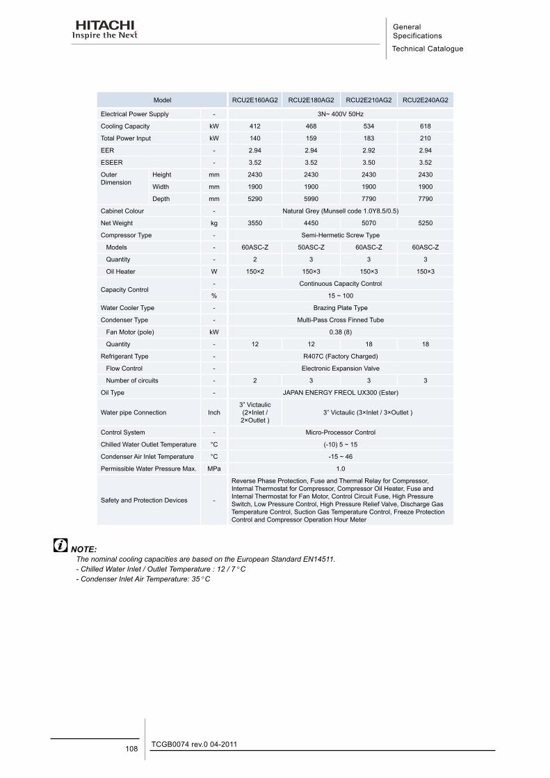
General Specifications
Technical Catalogue
TCGB0074 rev.0 04-2011108
Model RCU2E160AG2 RCU2E180AG2 RCU2E210AG2 RCU2E240AG2
Electrical Power Supply - 3N~ 400V 50Hz
Cooling Capacity kW 412 468 534 618
Total Power Input kW 140 159 183 210
EER - 2.94 2.94 2.92 2.94
ESEER - 3.52 3.52 3.50 3.52
Outer Dimension
Height mm 2430 2430 2430 2430
Width mm 1900 1900 1900 1900
Depth mm 5290 5990 7790 7790
Cabinet Colour - Natural Grey (Munsell code 1.0Y8.5/0.5)
Net Weight kg 3550 4450 5070 5250
Compressor Type - Semi-Hermetic Screw Type
Models - 60ASC-Z 50ASC-Z 60ASC-Z 60ASC-Z
Quantity - 2 3 3 3
Oil Heater W 150×2 150×3 150×3 150×3
Capacity Control- Continuous Capacity Control
% 15 ~ 100
Water Cooler Type - Brazing Plate Type
Condenser Type - Multi-Pass Cross Finned Tube
Fan Motor (pole) kW 0.38 (8)
Quantity - 12 12 18 18
Refrigerant Type - R407C (Factory Charged)
Flow Control - Electronic Expansion Valve
Number of circuits - 2 3 3 3
Oil Type - JAPAN ENERGY FREOL UX300 (Ester)
Water pipe Connection Inch3” Victaulic (2×Inlet / 2×Outlet )
3” Victaulic (3×Inlet / 3×Outlet )
Control System - Micro-Processor Control
Chilled Water Outlet Temperature °C (-10) 5 ~ 15
Condenser Air Inlet Temperature °C -15 ~ 46
Permissible Water Pressure Max. MPa 1.0
Safety and Protection Devices -
Reverse Phase Protection, Fuse and Thermal Relay for Compressor, Internal Thermostat for Compressor, Compressor Oil Heater, Fuse and Internal Thermostat for Fan Motor, Control Circuit Fuse, High Pressure Switch, Low Pressure Control, High Pressure Relief Valve, Discharge Gas Temperature Control, Suction Gas Temperature Control, Freeze Protection Control and Compressor Operation Hour Meter
NOTE:The nominal cooling capacities are based on the European Standard EN14511.- Chilled Water Inlet / Outlet Temperature : 12 / 7 °C- Condenser Inlet Air Temperature: 35 °C
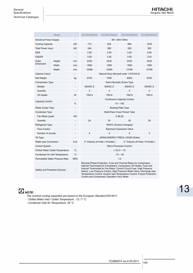
General SpecificationsTechnical Catalogue
13
109TCGB0074 rev.0 04-2011
Model RCU2E280AG2 RCU2E320AG2 RCU2E350AG2 RCU2E400AG2
Electrical Power Supply - 3N~ 400V 50Hz
Cooling Capacity kW 712 824 890 1030
Total Power Input kW 244 280 305 350
EER - 2.92 2.94 2.92 2.94
ESEER - 3.50 3.52 3.50 3.52
Outer Dimension
Height mm 2430 2430 2430 2430
Width mm 1900 1900 1900 1900
Depth mm 10290 10290 12790 12790
Cabinet Colour - Natural Grey (Munsell code 1.0Y8.5/0.5)
Net Weight kg 6750 7000 8450 8750
Compressor Type - Semi-Hermetic Screw Type
Models - 60ASC-Z 60ASC-Z 60ASC-Z 60ASC-Z
Quantity - 4 4 5 5
Oil Heater W 150×4 150×4 150×5 150×5
Capacity Control- Continuous Capacity Control
% 15 ~ 100
Water Cooler Type - Brazing Plate Type
Condenser Type - Multi-Pass Cross Finned Tube
Fan Motor (pole) kW 0.38 (8)
Quantity - 24 24 30 30
Refrigerant Type - R407C (Factory Charged)
Flow Control - Electronic Expansion Valve
Number of circuits - 4 4 5 5
Oil Type - JAPAN ENERGY FREOL UX300 (Ester)
Water pipe Connection Inch 3” Victaulic (4×Inlet / 4×Outlet ) 3” Victaulic (5×Inlet / 5×Outlet )
Control System - Micro-Processor Control
Chilled Water Outlet Temperature °C (-10) 5 ~ 15
Condenser Air Inlet Temperature °C -15 ~ 46
Permissible Water Pressure Max. MPa 1.0
Safety and Protection Devices -
Reverse Phase Protection, Fuse and Thermal Relay for Compressor, Internal Thermostat for Compressor, Compressor Oil Heater, Fuse and Internal Thermostat for Fan Motor, Control Circuit Fuse, High Pressure Switch, Low Pressure Control, High Pressure Relief Valve, Discharge Gas Temperature Control, Suction Gas Temperature Control, Freeze Protection Control and Compressor Operation Hour Meter
NOTE:The nominal cooling capacities are based on the European Standard EN14511.- Chilled Water Inlet / Outlet Temperature : 12 / 7 °C - Condenser Inlet Air Temperature: 35 °C
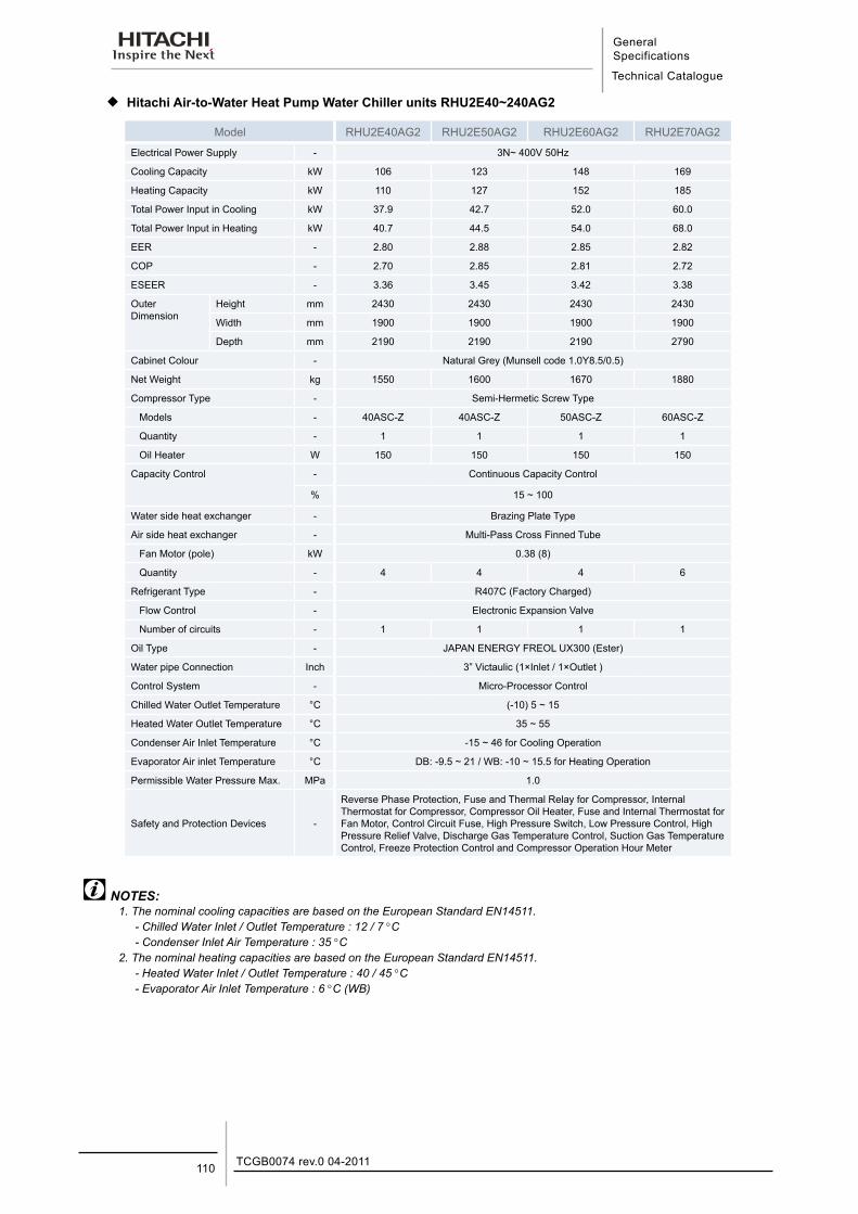
General Specifications
Technical Catalogue
TCGB0074 rev.0 04-2011110
¡ Hitachi Air-to-Water Heat Pump Water Chiller units RHU2E40~240AG2
Model RHU2E40AG2 RHU2E50AG2 RHU2E60AG2 RHU2E70AG2
Electrical Power Supply - 3N~ 400V 50Hz
Cooling Capacity kW 106 123 148 169
Heating Capacity kW 110 127 152 185
Total Power Input in Cooling kW 37.9 42.7 52.0 60.0
Total Power Input in Heating kW 40.7 44.5 54.0 68.0
EER - 2.80 2.88 2.85 2.82
COP - 2.70 2.85 2.81 2.72
ESEER - 3.36 3.45 3.42 3.38
Outer Dimension
Height mm 2430 2430 2430 2430
Width mm 1900 1900 1900 1900
Depth mm 2190 2190 2190 2790
Cabinet Colour - Natural Grey (Munsell code 1.0Y8.5/0.5)
Net Weight kg 1550 1600 1670 1880
Compressor Type - Semi-Hermetic Screw Type
Models - 40ASC-Z 40ASC-Z 50ASC-Z 60ASC-Z
Quantity - 1 1 1 1
Oil Heater W 150 150 150 150
Capacity Control - Continuous Capacity Control
% 15 ~ 100
Water side heat exchanger - Brazing Plate Type
Air side heat exchanger - Multi-Pass Cross Finned Tube
Fan Motor (pole) kW 0.38 (8)
Quantity - 4 4 4 6
Refrigerant Type - R407C (Factory Charged)
Flow Control - Electronic Expansion Valve
Number of circuits - 1 1 1 1
Oil Type - JAPAN ENERGY FREOL UX300 (Ester)
Water pipe Connection Inch 3” Victaulic (1×Inlet / 1×Outlet )
Control System - Micro-Processor Control
Chilled Water Outlet Temperature °C (-10) 5 ~ 15
Heated Water Outlet Temperature °C 35 ~ 55
Condenser Air Inlet Temperature °C -15 ~ 46 for Cooling Operation
Evaporator Air inlet Temperature °C DB: -9.5 ~ 21 / WB: -10 ~ 15.5 for Heating Operation
Permissible Water Pressure Max. MPa 1.0
Safety and Protection Devices -
Reverse Phase Protection, Fuse and Thermal Relay for Compressor, Internal Thermostat for Compressor, Compressor Oil Heater, Fuse and Internal Thermostat for Fan Motor, Control Circuit Fuse, High Pressure Switch, Low Pressure Control, High Pressure Relief Valve, Discharge Gas Temperature Control, Suction Gas Temperature Control, Freeze Protection Control and Compressor Operation Hour Meter
NOTES:1. The nominal cooling capacities are based on the European Standard EN14511.
- Chilled Water Inlet / Outlet Temperature : 12 / 7 °C- Condenser Inlet Air Temperature : 35 °C
2. The nominal heating capacities are based on the European Standard EN14511.- Heated Water Inlet / Outlet Temperature : 40 / 45 °C- Evaporator Air Inlet Temperature : 6 °C (WB)
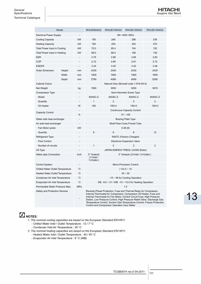
General SpecificationsTechnical Catalogue
13
111TCGB0074 rev.0 04-2011
Model RHU2E80AG2 RHU2E100AG2 RHU2E120AG2 RHU2E140AG2
Electrical Power Supply - 3N~ 400V 50Hz
Cooling Capacity kW 195 246 296 338
Heating Capacity kW 185 254 304 370
Total Power Input in Cooling kW 70.0 85.4 104 120
Total Power Input in Heating kW 68.0 89.0 108 136
EER - 2.79 2.88 2.85 2.82
COP - 2.72 2.85 2.81 2.72
ESEER - 3.34 3.45 3.42 3.38
Outer Dimension Height mm 2430 2430 2430 2430
Width mm 1900 1900 1900 1900
Depth mm 2790 4090 4090 5290
Cabinet Colour - Natural Grey (Munsell code 1.0Y8.5/0.5)
Net Weight kg 1950 3050 3250 3670
Compressor Type - Semi-Hermetic Screw Type
Model - 60ASC-Z 40ASC-Z 50ASC-Z 60ASC-Z
Quantity - 1 2 2 2
Oil Heater W 150 150×2 150×2 150×2
Capacity Control- Continuous Capacity Control
% 15 ~ 100
Water side heat exchanger - Brazing Plate Type
Air side heat exchanger - Multi-Pass Cross Finned Tube
Fan Motor (pole) kW 0.38 (8)
Quantity - 6 8 8 12
Refrigerant Type - R407C (Factory Charged)
Flow Control - Electronic Expansion Valve
Number of circuits - 1 2 2 2
Oil Type - JAPAN ENERGY FREOL UX300 (Ester)
Water pipe Connection Inch 3” Victaulic (1×Inlet / 1×Outlet )
3” Victaulic (2×Inlet / 2×Outlet )
Control System - Micro-Processor Control
Chilled Water Outlet Temperature °C (-10) 5 ~ 15
Heated Water Outlet Temperature °C 35 ~ 55
Condenser Air Inlet Temperature °C -15 ~ 46 for Cooling Operation
Evaporator Air inlet Temperature °C DB: -9.5 ~ 21 / WB: -10 ~ 15.5 for Heating Operation
Permissible Water Pressure Max. MPa 1.0
Safety and Protection Devices
-
Reverse Phase Protection, Fuse and Thermal Relay for Compressor, Internal Thermostat for Compressor, Compressor Oil Heater, Fuse and Internal Thermostat for Fan Motor, Control Circuit Fuse, High Pressure Switch, Low Pressure Control, High Pressure Relief Valve, Discharge Gas Temperature Control, Suction Gas Temperature Control, Freeze Protection Control and Compressor Operation Hour Meter
NOTES:1. The nominal cooling capacities are based on the European Standard EN14511.
- Chilled Water Inlet / Outlet Temperature : 12 / 7 °C- Condenser Inlet Air Temperature : 35 °C
2. The nominal heating capacities are based on the European Standard EN14511.- Heated Water Inlet / Outlet Temperature : 40 / 45 °C- Evaporator Air Inlet Temperature : 6 °C (WB)
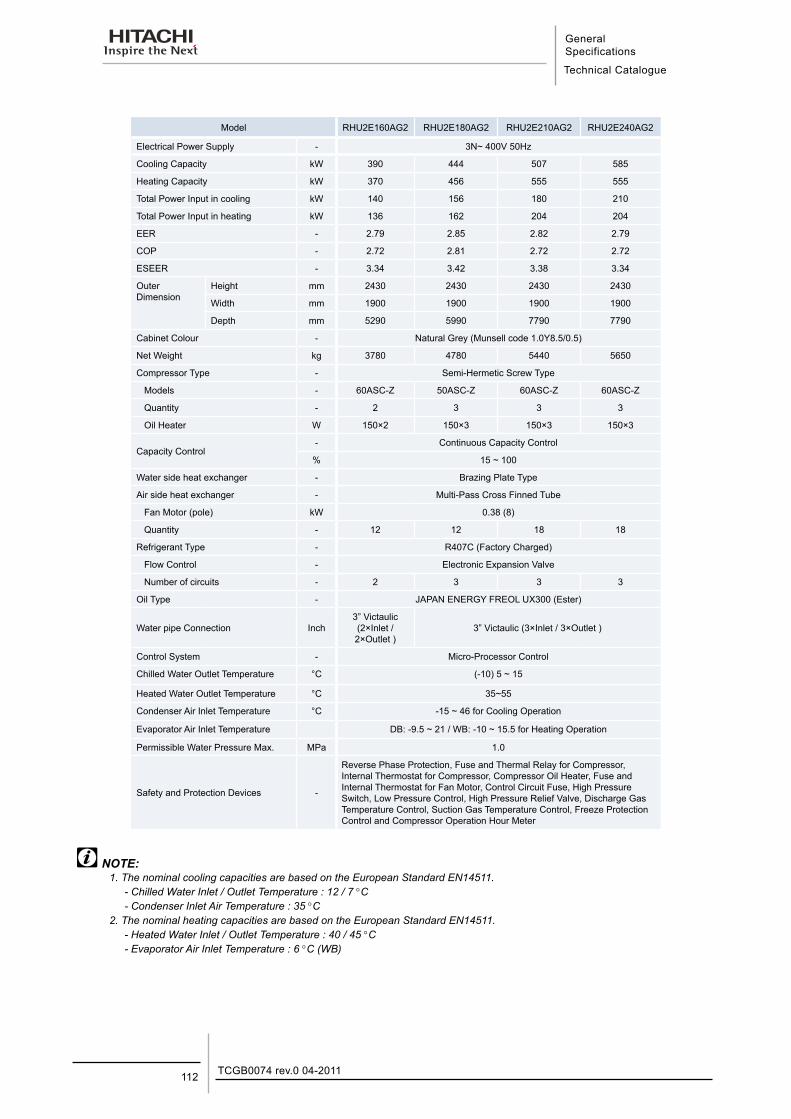
General Specifications
Technical Catalogue
TCGB0074 rev.0 04-2011112
Model RHU2E160AG2 RHU2E180AG2 RHU2E210AG2 RHU2E240AG2
Electrical Power Supply - 3N~ 400V 50Hz
Cooling Capacity kW 390 444 507 585
Heating Capacity kW 370 456 555 555
Total Power Input in cooling kW 140 156 180 210
Total Power Input in heating kW 136 162 204 204
EER - 2.79 2.85 2.82 2.79
COP - 2.72 2.81 2.72 2.72
ESEER - 3.34 3.42 3.38 3.34
Outer Dimension
Height mm 2430 2430 2430 2430
Width mm 1900 1900 1900 1900
Depth mm 5290 5990 7790 7790
Cabinet Colour - Natural Grey (Munsell code 1.0Y8.5/0.5)
Net Weight kg 3780 4780 5440 5650
Compressor Type - Semi-Hermetic Screw Type
Models - 60ASC-Z 50ASC-Z 60ASC-Z 60ASC-Z
Quantity - 2 3 3 3
Oil Heater W 150×2 150×3 150×3 150×3
Capacity Control- Continuous Capacity Control
% 15 ~ 100
Water side heat exchanger - Brazing Plate Type
Air side heat exchanger - Multi-Pass Cross Finned Tube
Fan Motor (pole) kW 0.38 (8)
Quantity - 12 12 18 18
Refrigerant Type - R407C (Factory Charged)
Flow Control - Electronic Expansion Valve
Number of circuits - 2 3 3 3
Oil Type - JAPAN ENERGY FREOL UX300 (Ester)
Water pipe Connection Inch3” Victaulic (2×Inlet / 2×Outlet )
3” Victaulic (3×Inlet / 3×Outlet )
Control System - Micro-Processor Control
Chilled Water Outlet Temperature °C (-10) 5 ~ 15
Heated Water Outlet Temperature °C 35~55
Condenser Air Inlet Temperature °C -15 ~ 46 for Cooling Operation
Evaporator Air Inlet Temperature DB: -9.5 ~ 21 / WB: -10 ~ 15.5 for Heating Operation
Permissible Water Pressure Max. MPa 1.0
Safety and Protection Devices -
Reverse Phase Protection, Fuse and Thermal Relay for Compressor, Internal Thermostat for Compressor, Compressor Oil Heater, Fuse and Internal Thermostat for Fan Motor, Control Circuit Fuse, High Pressure Switch, Low Pressure Control, High Pressure Relief Valve, Discharge Gas Temperature Control, Suction Gas Temperature Control, Freeze Protection Control and Compressor Operation Hour Meter
NOTE:1. The nominal cooling capacities are based on the European Standard EN14511.
- Chilled Water Inlet / Outlet Temperature : 12 / 7 °C- Condenser Inlet Air Temperature : 35 °C
2. The nominal heating capacities are based on the European Standard EN14511.- Heated Water Inlet / Outlet Temperature : 40 / 45 °C- Evaporator Air Inlet Temperature : 6 °C (WB)
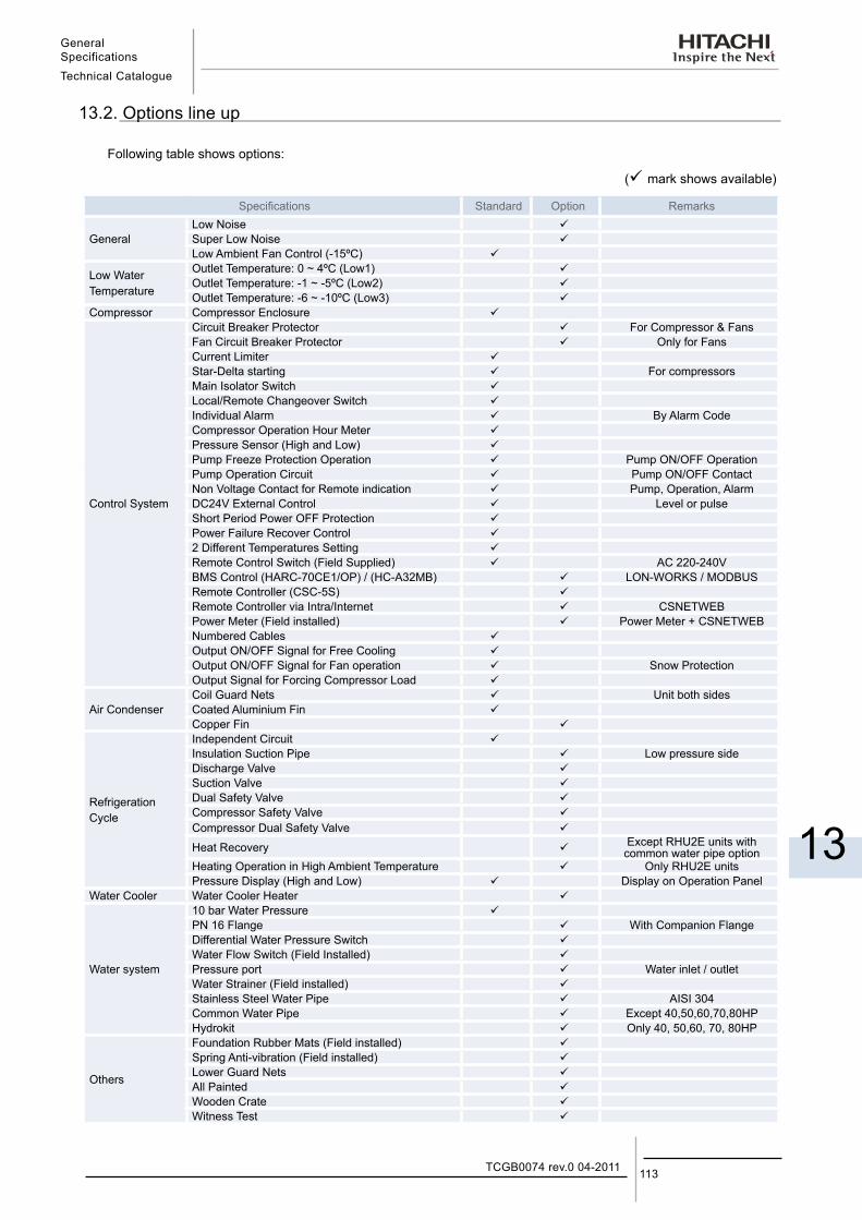
General SpecificationsTechnical Catalogue
13
113TCGB0074 rev.0 04-2011
13.2. Options line up
Following table shows options:
( mark shows available)
Specifications Standard Option Remarks
GeneralLow Noise Super Low Noise Low Ambient Fan Control (-15ºC)
Low WaterTemperature
Outlet Temperature: 0 ~ 4ºC (Low1) Outlet Temperature: -1 ~ -5ºC (Low2) Outlet Temperature: -6 ~ -10ºC (Low3)
Compressor Compressor Enclosure
Control System
Circuit Breaker Protector For Compressor & FansFan Circuit Breaker Protector Only for FansCurrent Limiter Star-Delta starting For compressorsMain Isolator Switch Local/Remote Changeover Switch Individual Alarm By Alarm CodeCompressor Operation Hour Meter Pressure Sensor (High and Low) Pump Freeze Protection Operation Pump ON/OFF OperationPump Operation Circuit Pump ON/OFF ContactNon Voltage Contact for Remote indication Pump, Operation, AlarmDC24V External Control Level or pulseShort Period Power OFF Protection Power Failure Recover Control 2 Different Temperatures Setting Remote Control Switch (Field Supplied) AC 220-240VBMS Control (HARC-70CE1/OP) / (HC-A32MB) LON-WORKS / MODBUSRemote Controller (CSC-5S) Remote Controller via Intra/Internet CSNETWEBPower Meter (Field installed) Power Meter + CSNETWEBNumbered Cables Output ON/OFF Signal for Free Cooling Output ON/OFF Signal for Fan operation Snow ProtectionOutput Signal for Forcing Compressor Load
Air CondenserCoil Guard Nets Unit both sidesCoated Aluminium Fin Copper Fin
Refrigeration Cycle
Independent Circuit Insulation Suction Pipe Low pressure sideDischarge Valve Suction Valve Dual Safety Valve Compressor Safety Valve Compressor Dual Safety Valve
Heat Recovery Except RHU2E units with common water pipe option
Heating Operation in High Ambient Temperature Only RHU2E unitsPressure Display (High and Low) Display on Operation Panel
Water Cooler Water Cooler Heater
Water system
10 bar Water Pressure PN 16 Flange With Companion FlangeDifferential Water Pressure Switch Water Flow Switch (Field Installed) Pressure port Water inlet / outletWater Strainer (Field installed) Stainless Steel Water Pipe AISI 304Common Water Pipe Except 40,50,60,70,80HPHydrokit Only 40, 50,60, 70, 80HP
Others
Foundation Rubber Mats (Field installed) Spring Anti-vibration (Field installed) Lower Guard Nets All Painted Wooden Crate Witness Test

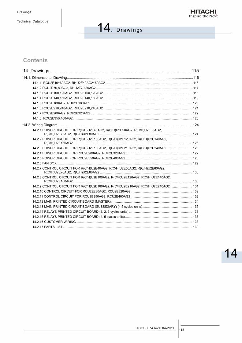
Drawings
Technical Catalogue
14
14. D r a w i n g s
115TCGB0074 rev.0 04-2011
Contents
14. Drawings.................................................................................................................. 11514.1. Dimensional Drawing............................................................................................................................116
14.1.1. RCU2E40~60AG2, RHU2E40AG2~60AG2 .................................................................................................11614.1.2 RCU2E70,80AG2, RHU2E70,80AG2 ...........................................................................................................11714.1.3 RCU2E100,120AG2, RHU2E100,120AG2 ...................................................................................................11814.1.4 RCU2E140,160AG2, RHU2E140,160AG2 ...................................................................................................11914.1.5 RCU2E180AG2, RHU2E180AG2 ................................................................................................................ 12014.1.6 RCU2E210,240AG2, RHU2E210,240AG2 .................................................................................................. 12114.1.7 RCU2E280AG2, RCU2E320AG2 ................................................................................................................ 12214.1.8. RCU2E350,400AG2 .................................................................................................................................... 123
14.2. Wiring Diagram .................................................................................................................................... 12414.2.1 POWER CIRCUIT FOR R(C/H)U2E40AG2, R(C/H)U2E50AG2, R(C/H)U2E60AG2,
R(C/H)U2E70AG2, R(C/H)U2E80AG2 ...................................................................................................... 12414.2.2 POWER CIRCUIT FOR R(C/H)U2E100AG2, R(C/H)U2E120AG2, R(C/H)U2E140AG2,
R(C/H)U2E160AG2 ................................................................................................................................... 12514.2.3 POWER CIRCUIT FOR R(C/H)U2E180AG2, R(C/H)U2E210AG2, R(C/H)U2E240AG2 ............................ 12614.2.4 POWER CIRCUIT FOR RCU2E280AG2, RCU2E320AG2 .......................................................................... 12714.2.5 POWER CIRCUIT FOR RCU2E350AG2, RCU2E400AG2 .......................................................................... 12814.2.6 FAN BOX ...................................................................................................................................................... 12914.2.7 CONTROL CIRCUIT FOR R(C/H)U2E40AG2, R(C/H)U2E50AG2, R(C/H)U2E60AG2,
R(C/H)U2E70AG2, R(C/H)U2E80AG2 ...................................................................................................... 13014.2.8 CONTROL CIRCUIT FOR R(C/H)U2E100AG2, R(C/H)U2E120AG2, R(C/H)U2E140AG2,
R(C/H)U2E160AG2 .................................................................................................................................... 13014.2.9 CONTROL CIRCUIT FOR R(C/H)U2E180AG2, R(C/H)U2E210AG2, R(C/H)U2E240AG2 ........................ 13114.2.10 CONTROL CIRCUIT FOR RCU2E280AG2, RCU2E320AG2 .................................................................... 13214.2.11 CONTROL CIRCUIT FOR RCU2E350AG2, RCU2E400AG2 .................................................................... 13314.2.12 MAIN PRINTED CIRCUIT BOARD (MASTER) .......................................................................................... 13414.2.13 MAIN PRINTED CIRCUIT BOARD (SUBSIDIARY) (4,5 cycles units) ....................................................... 13514.2.14 RELAYS PRINTED CIRCUIT BOARD (1, 2, 3 cycles units) ...................................................................... 13614.2.15 RELAYS PRINTED CIRCUIT BOARD (4, 5 cycles units) .......................................................................... 13714.2.16 CUSTOMER WIRING ................................................................................................................................ 13814.2.17 PARTS LIST ............................................................................................................................................... 139
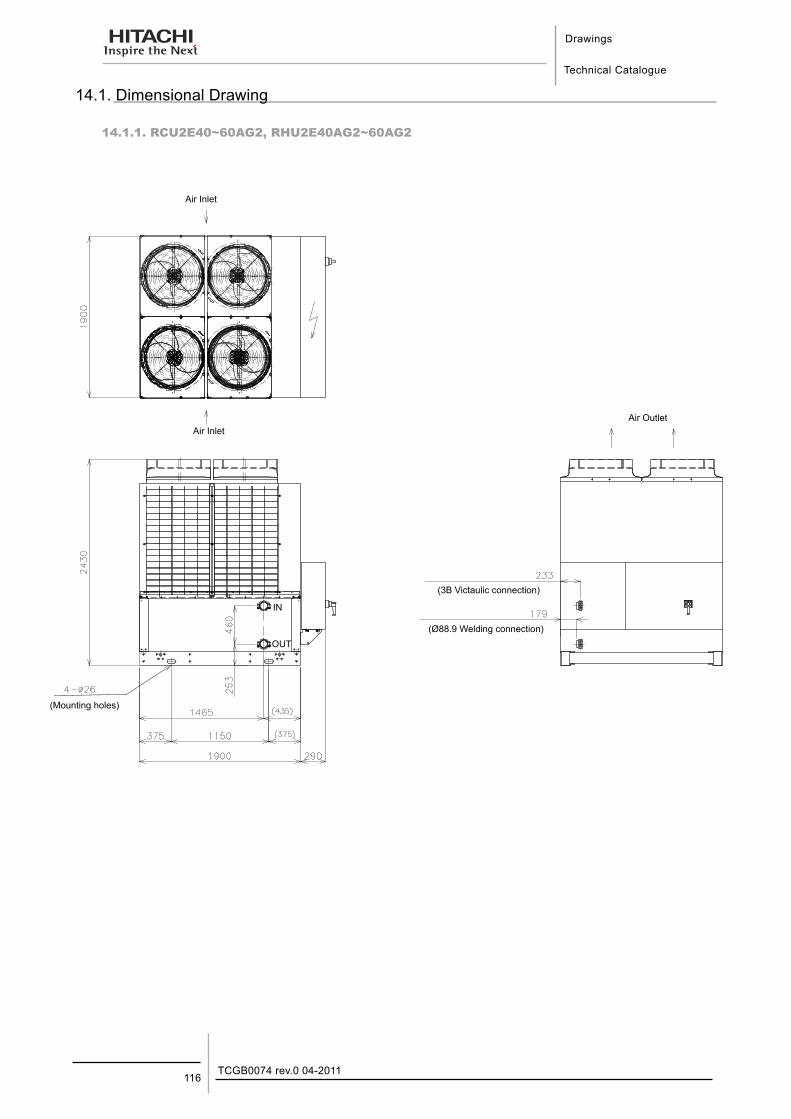
Drawings
Technical Catalogue
TCGB0074 rev.0 04-2011116
14.1. Dimensional Drawing
14.1.1. RCU2E40~60AG2, RHU2E40AG2~60AG2
Air Inlet
(Mounting holes)
(Ø88.9 Welding connection)
(3B Victaulic connection)
Air InletAir Outlet
IN
OUT
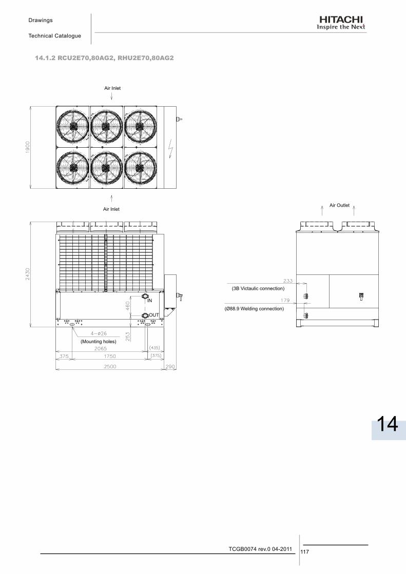
Drawings
Technical Catalogue
14
117TCGB0074 rev.0 04-2011
14.1.2 RCU2E70,80AG2, RHU2E70,80AG2
Air Inlet
Air InletAir Outlet
(Mounting holes)
(Ø88.9 Welding connection)
(3B Victaulic connection)
IN
OUT
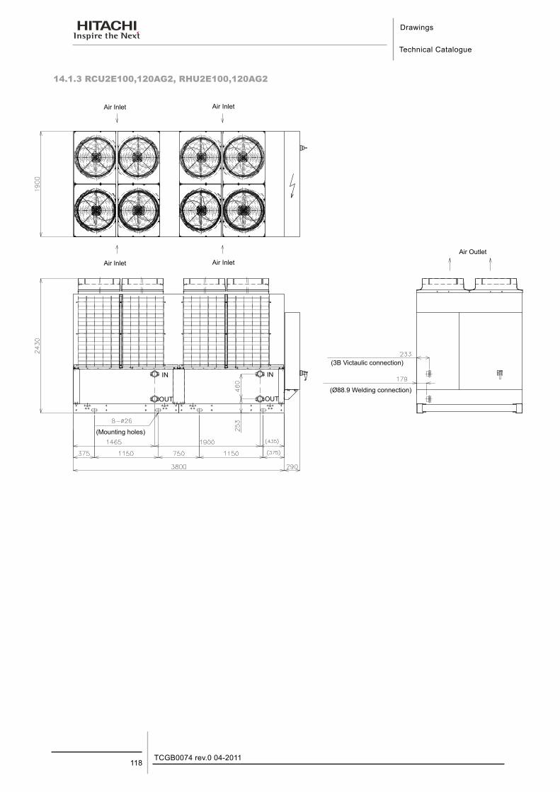
Drawings
Technical Catalogue
TCGB0074 rev.0 04-2011118
14.1.3 RCU2E100,120AG2, RHU2E100,120AG2
Air Inlet
Air Inlet
Air Inlet
Air InletAir Outlet
(Mounting holes)
(Ø88.9 Welding connection)
(3B Victaulic connection)
IN
OUT
IN
OUT
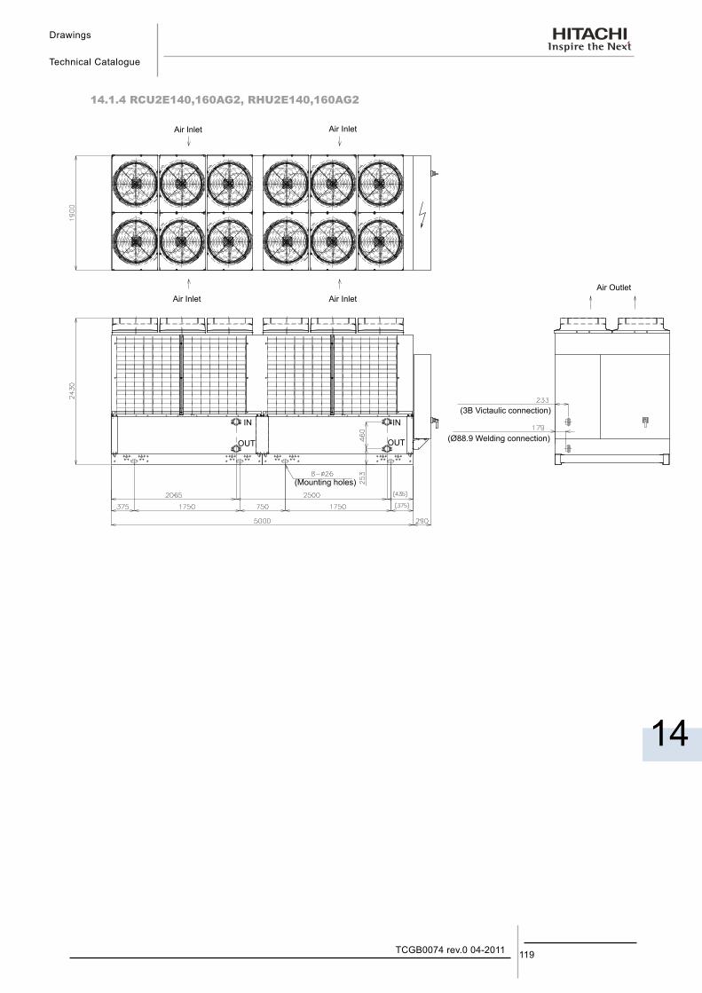
Drawings
Technical Catalogue
14
119TCGB0074 rev.0 04-2011
14.1.4 RCU2E140,160AG2, RHU2E140,160AG2
Air Inlet Air Inlet
Air InletAir InletAir Outlet
(Mounting holes)
(Ø88.9 Welding connection)
(3B Victaulic connection)IN
OUT
IN
OUT
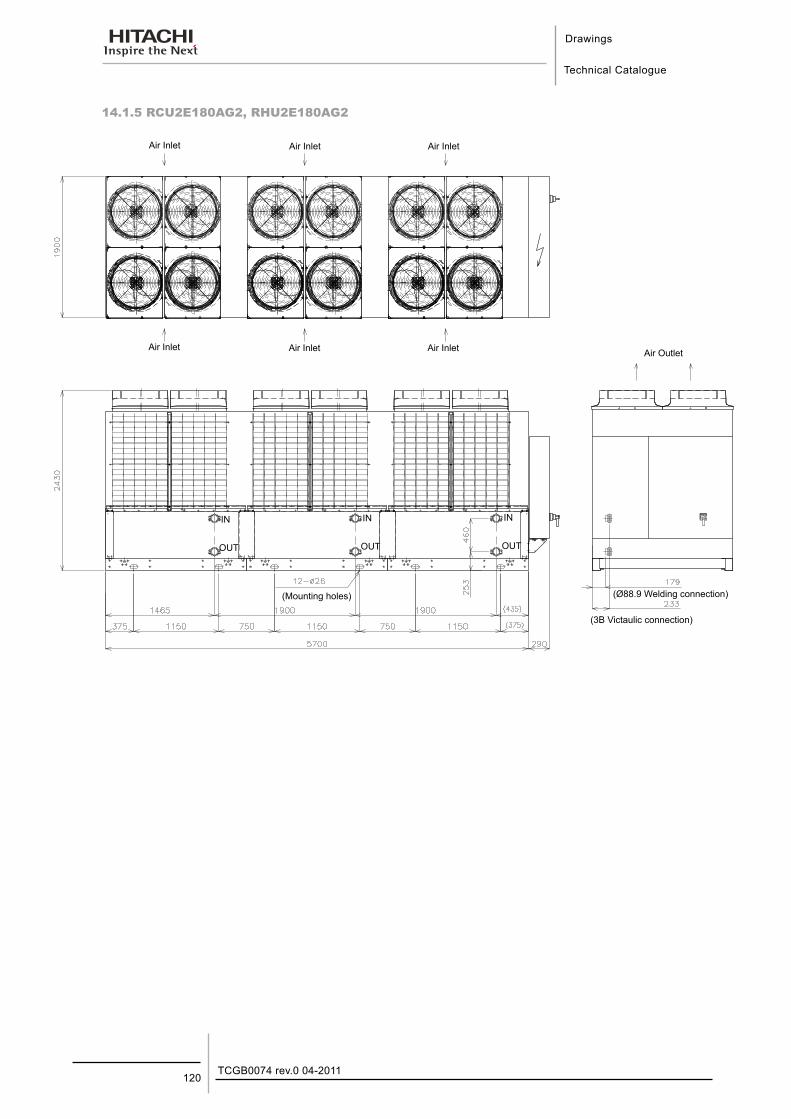
Drawings
Technical Catalogue
TCGB0074 rev.0 04-2011120
14.1.5 RCU2E180AG2, RHU2E180AG2
Air Inlet
Air Inlet
Air Inlet
Air Inlet
Air Inlet
Air Inlet Air Outlet
(Mounting holes) (Ø88.9 Welding connection)
(3B Victaulic connection)
IN
OUT
IN
OUT
IN
OUT
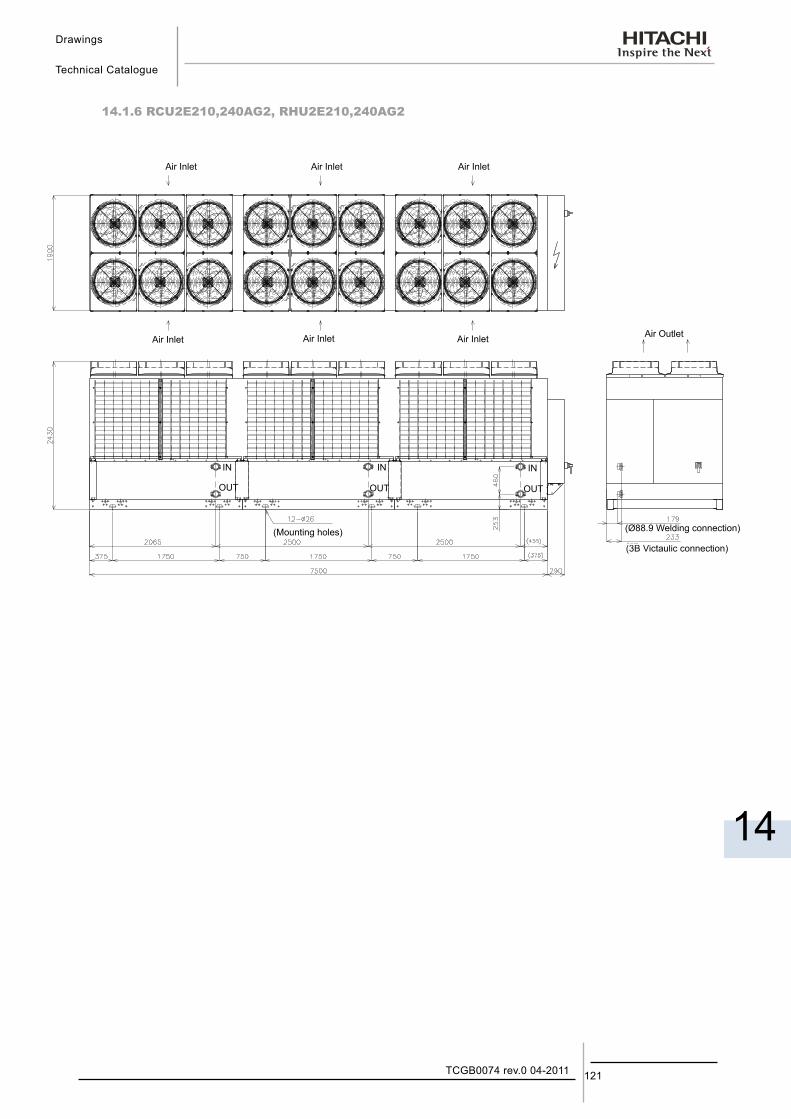
Drawings
Technical Catalogue
14
121TCGB0074 rev.0 04-2011
14.1.6 RCU2E210,240AG2, RHU2E210,240AG2
Air Inlet Air Inlet
Air Inlet
Air Inlet
Air Inlet Air Outlet
(Mounting holes)
IN IN IN
OUT OUT OUT
(Ø88.9 Welding connection)
(3B Victaulic connection)
Air Inlet
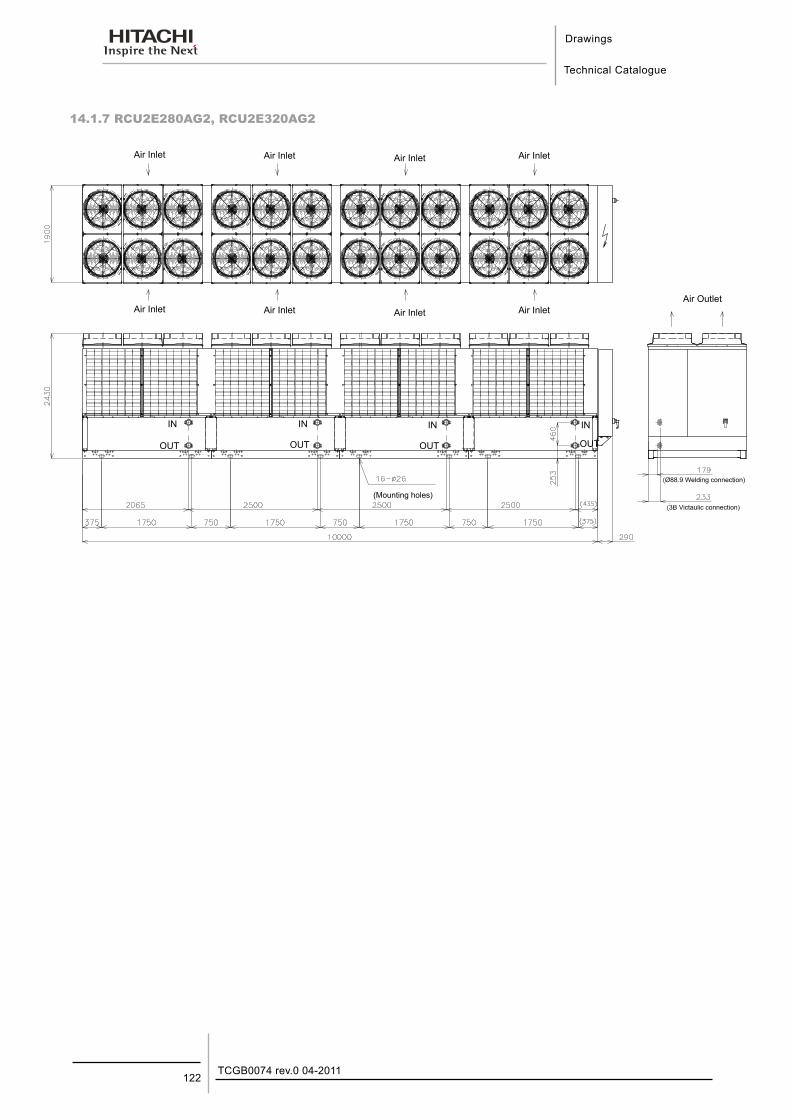
Drawings
Technical Catalogue
TCGB0074 rev.0 04-2011122
14.1.7 RCU2E280AG2, RCU2E320AG2
Air Inlet Air Inlet Air Inlet Air Inlet
IN
OUT
Air Outlet
(Mounting holes)
(Ø88.9 Welding connection)
Air Inlet Air Inlet Air Inlet Air Inlet
IN
OUT
IN
OUT
(3B Victaulic connection)
IN
OUT
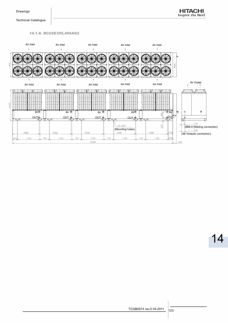
Drawings
Technical Catalogue
14
123TCGB0074 rev.0 04-2011
14.1.8. RCU2E350,400AG2
Air Inlet Air Inlet Air Inlet Air Inlet
IN IN IN IN
OUT OUT OUT OUT
Air Outlet
(Mounting holes)(Ø88.9 Welding connection)
(3B Victaulic connection)
Air Inlet
IN
OUT
Air Inlet Air Inlet Air Inlet Air Inlet Air Inlet
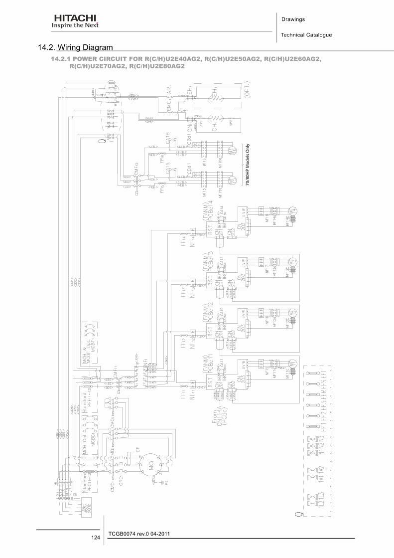
Drawings
Technical Catalogue
TCGB0074 rev.0 04-2011124
14.2. Wiring Diagram14.2.1 POWER CIRCUIT FOR R(C/H)U2E40AG2, R(C/H)U2E50AG2, R(C/H)U2E60AG2,
R(C/H)U2E70AG2, R(C/H)U2E80AG2
70/8
0HP
Mod
els
Onl
y
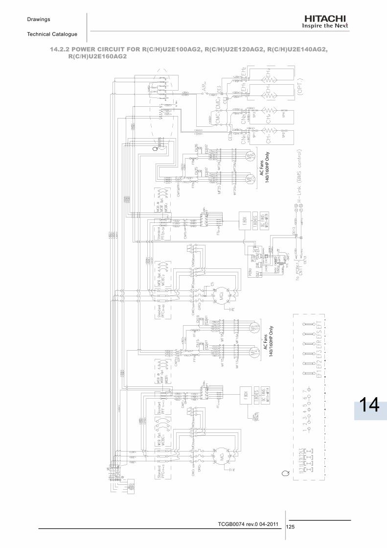
Drawings
Technical Catalogue
14
125TCGB0074 rev.0 04-2011
14.2.2 POWER CIRCUIT FOR R(C/H)U2E100AG2, R(C/H)U2E120AG2, R(C/H)U2E140AG2, R(C/H)U2E160AG2
AC F
ans
140/
160H
P O
nly
AC F
ans
140/
160H
P O
nly
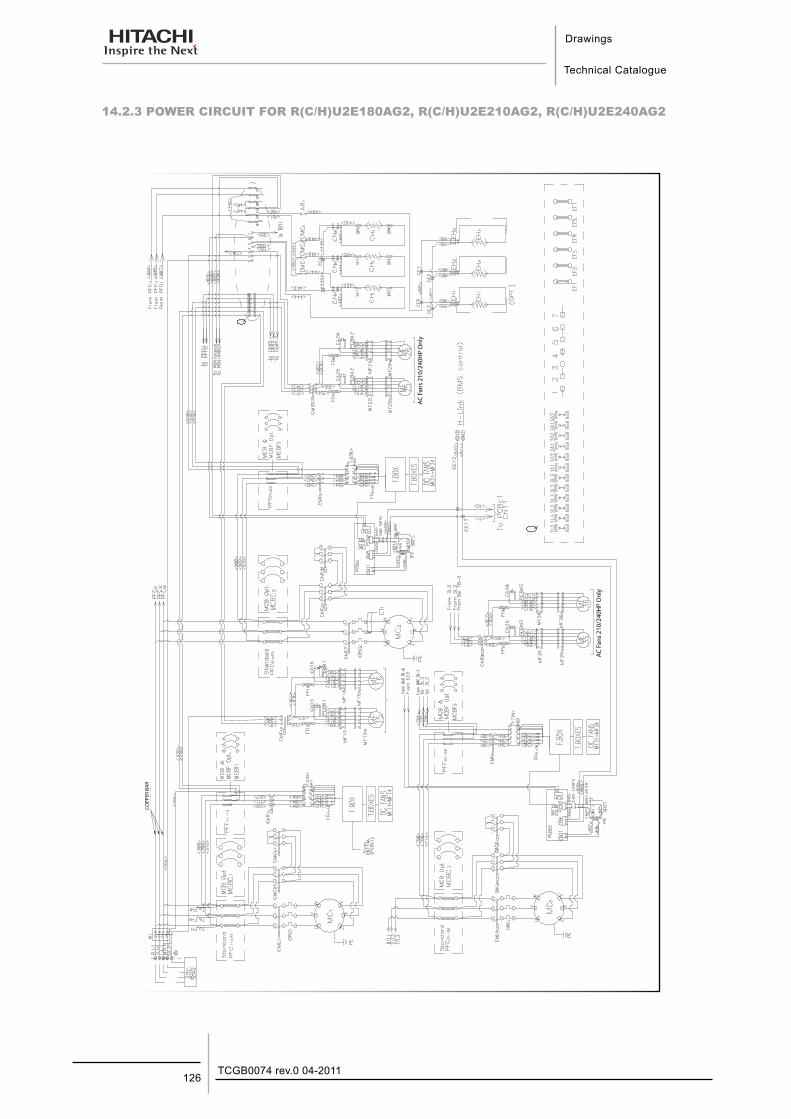
Drawings
Technical Catalogue
TCGB0074 rev.0 04-2011126
14.2.3 POWER CIRCUIT FOR R(C/H)U2E180AG2, R(C/H)U2E210AG2, R(C/H)U2E240AG2
AC
Fan
s 21
0/24
0HP
On
ly
AC
Fan
s 21
0/24
0HP
On
ly
CO
PPER
BA
RCO
PPER
BA
R
AC F
ans
210/
240H
P O
nly
AC F
ans
210/
240H
P O
nly
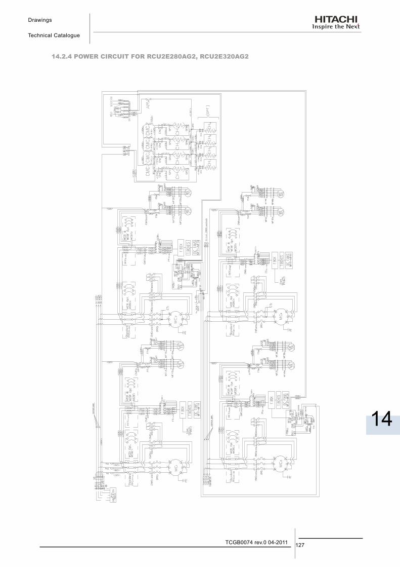
Drawings
Technical Catalogue
14
127TCGB0074 rev.0 04-2011
14.2.4 POWER CIRCUIT FOR RCU2E280AG2, RCU2E320AG2
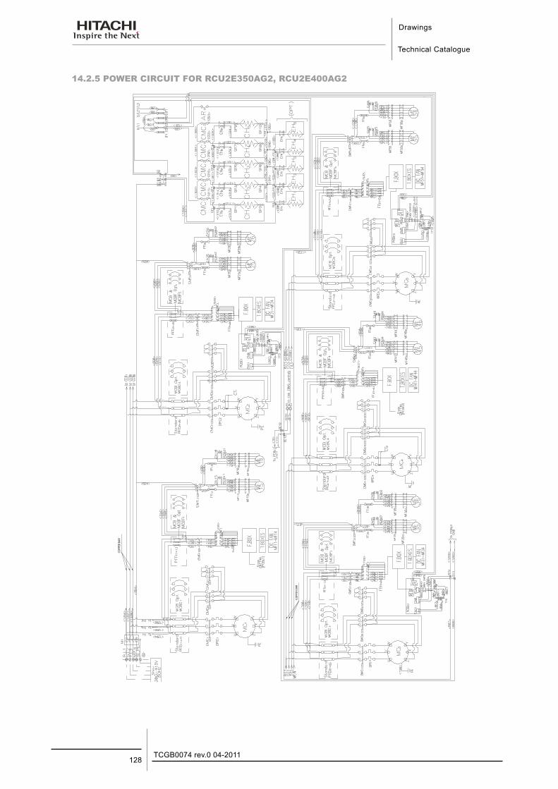
Drawings
Technical Catalogue
TCGB0074 rev.0 04-2011128
14.2.5 POWER CIRCUIT FOR RCU2E350AG2, RCU2E400AG2
CO
PPER
BA
R
CO
PPER
BA
RCO
PPER
BA
R
COPP
ER B
AR
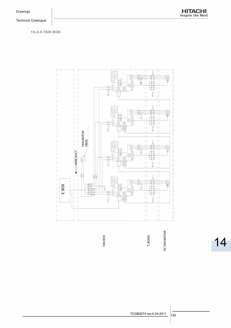
Drawings
Technical Catalogue
14
129TCGB0074 rev.0 04-2011
14.2.6 FAN BOX
WIR
E D
UC
T
FAN
BO
X
T. B
OXE
S
DC
FAN
MO
TOR
E. B
OX
FAN
MO
TOR
FBO
X
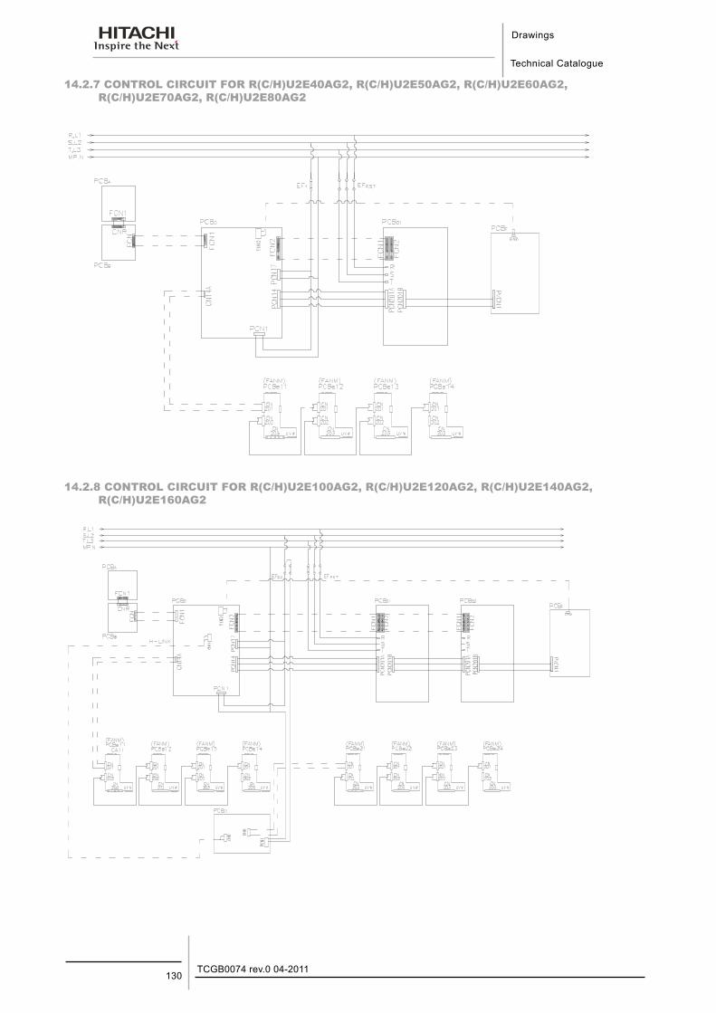
Drawings
Technical Catalogue
TCGB0074 rev.0 04-2011130
14.2.7 CONTROL CIRCUIT FOR R(C/H)U2E40AG2, R(C/H)U2E50AG2, R(C/H)U2E60AG2, R(C/H)U2E70AG2, R(C/H)U2E80AG2
14.2.8 CONTROL CIRCUIT FOR R(C/H)U2E100AG2, R(C/H)U2E120AG2, R(C/H)U2E140AG2, R(C/H)U2E160AG2
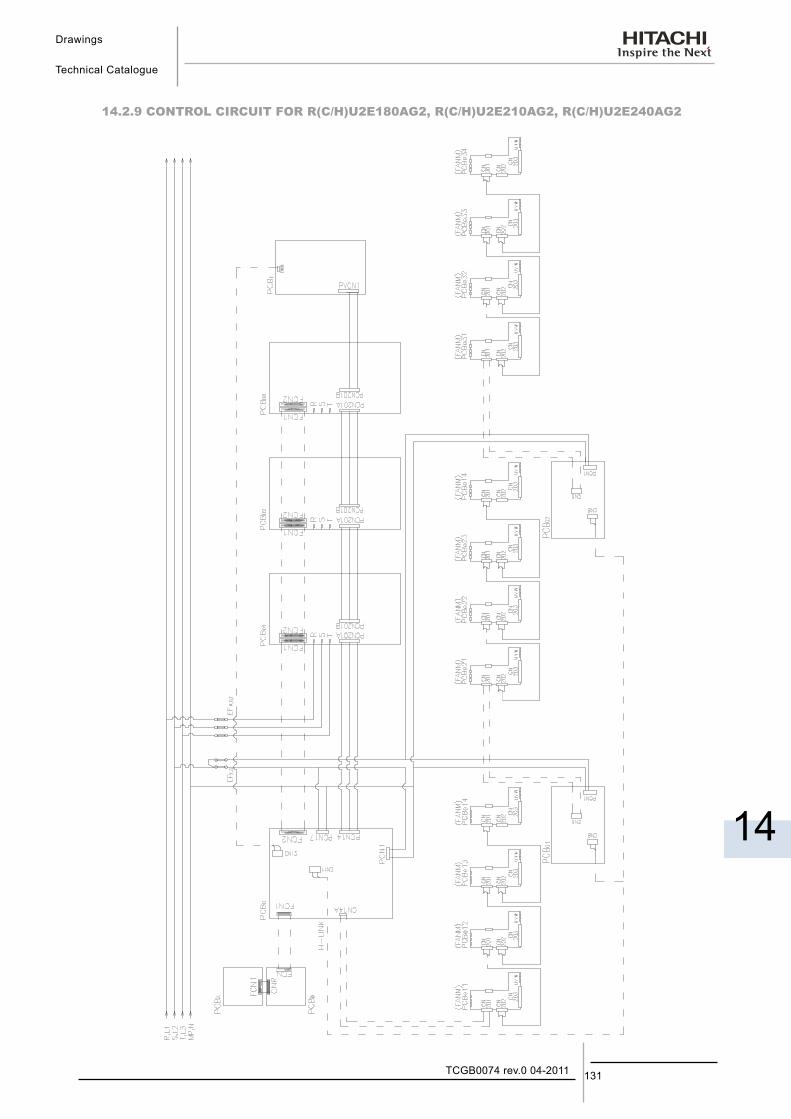
Drawings
Technical Catalogue
14
131TCGB0074 rev.0 04-2011
14.2.9 CONTROL CIRCUIT FOR R(C/H)U2E180AG2, R(C/H)U2E210AG2, R(C/H)U2E240AG2
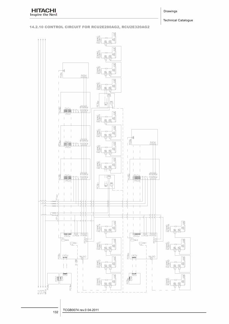
Drawings
Technical Catalogue
TCGB0074 rev.0 04-2011132
14.2.10 CONTROL CIRCUIT FOR RCU2E280AG2, RCU2E320AG2
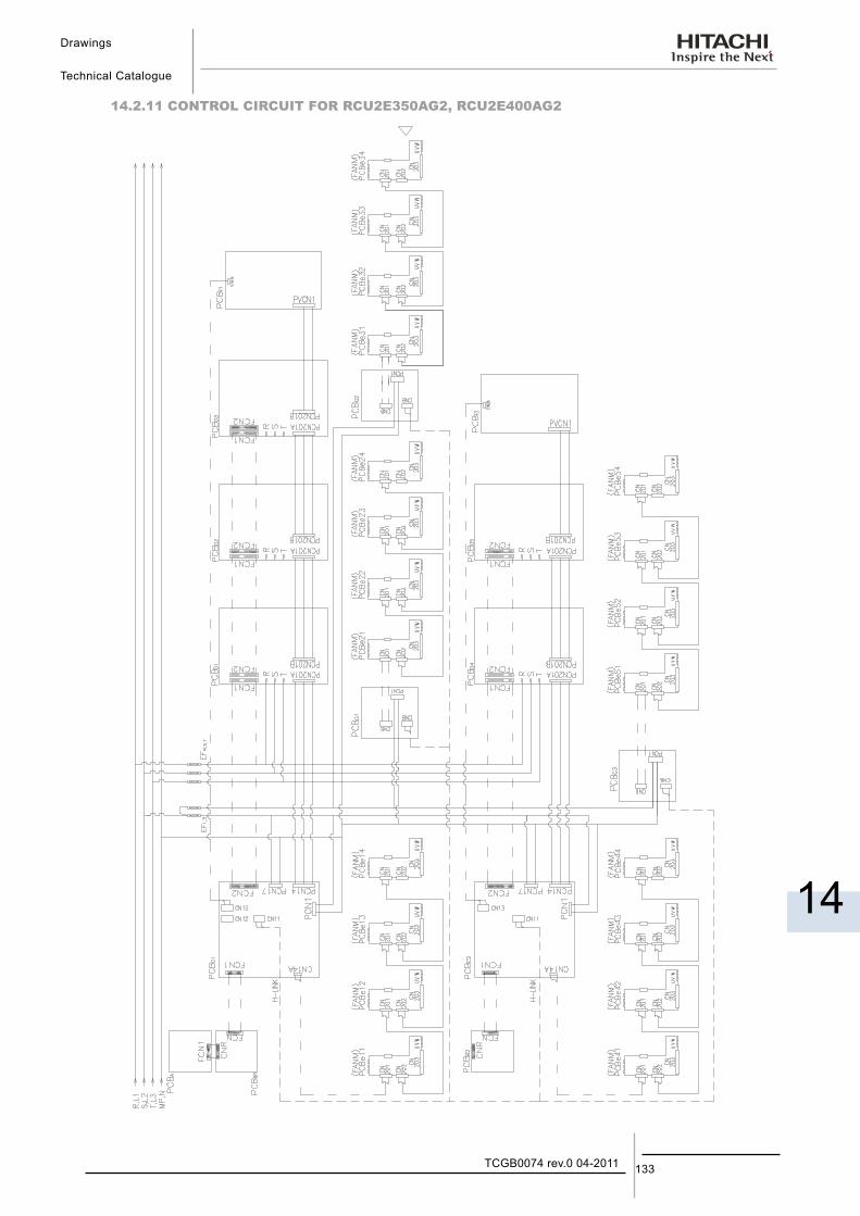
Drawings
Technical Catalogue
14
133TCGB0074 rev.0 04-2011
14.2.11 CONTROL CIRCUIT FOR RCU2E350AG2, RCU2E400AG2
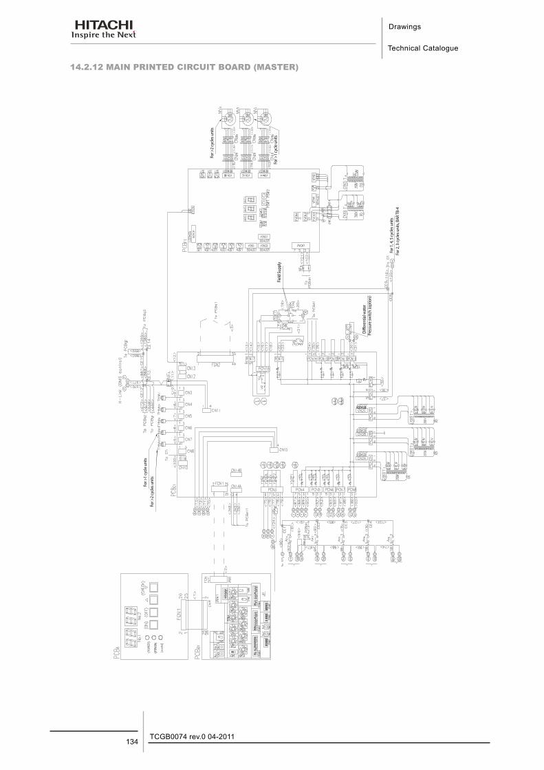
Drawings
Technical Catalogue
TCGB0074 rev.0 04-2011134
14.2.12 MAIN PRINTED CIRCUIT BOARD (MASTER)
For >
2 cy
cles u
nits
For >
1 cy
cle u
nits
Field
Sup
ply
For 1
, 4, 5
cycle
s uni
tsFo
r 2, 3
cycle
s uni
ts, B
AR TB
-4
Diffe
rent
ial w
ater
Pres
sure
switc
h (o
ptio
n)
For >
2 cy
cles u
nits
For >
1 cy
cle u
nits
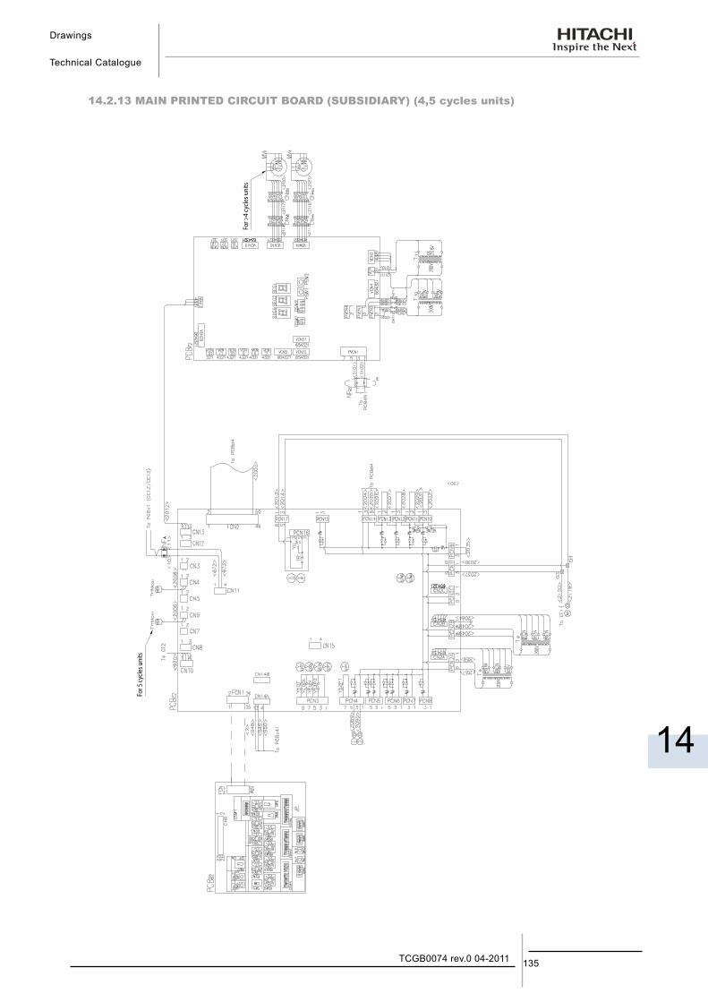
Drawings
Technical Catalogue
14
135TCGB0074 rev.0 04-2011
14.2.13 MAIN PRINTED CIRCUIT BOARD (SUBSIDIARY) (4,5 cycles units)
For
5 cy
cles
un
its
For
>4
cycl
es u
nit
s
For 5
cycle
s uni
ts
For >
4 cy
cles u
nits
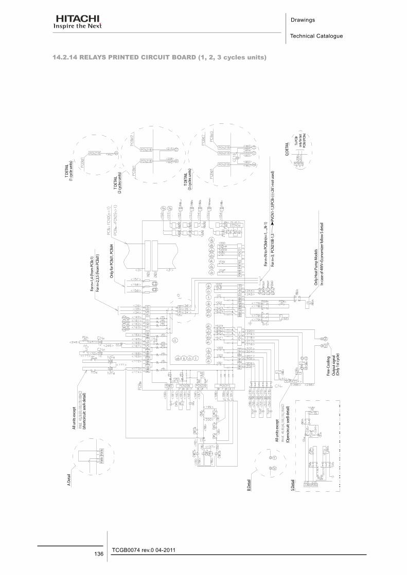
Drawings
Technical Catalogue
TCGB0074 rev.0 04-2011136
14.2.14 RELAYS PRINTED CIRCUIT BOARD (1, 2, 3 cycles units)
All u
nits
exc
ept
(sho
rtci
rcui
t: se
e A
deta
il)
Onl
y fo
r PCB
d1, P
CBd4
Onl
y HP
Mod
els
In ca
se o
f 4W
V+Ec
onom
izer f
ollo
w S
det
ail
All u
nits
exc
ept
(Ope
n ci
rcui
t: Se
e B
deta
il)
Free
-Coo
ling
Out
put s
igna
l(O
nly
1st c
ycle
)
T DE
TAIL
(1 cy
cle u
nits
)
T DE
TAIL
(2 cy
cles u
nits
)
T DE
TAIL
(3 cy
cles u
nits
)
Q D
ETAI
L To PC
BF
only
for la
stPC
Bd (P
CBN)
Onl
y Hea
t Pum
p M
odel
sIn
case
of 4
WV+
Econ
omize
r fol
low
S d
etai
l
For n
<N to
PCB
dn(n
=1, ..
.,N-1
)
For n
=3; P
CN21
0B-1
,3
PVCN
1-1,
3(PC
BF1)
(<26
’>no
t use
d)
Onl
y for
PCB
d1, P
CBd4
For n
=1,4
(Fro
m P
CBc1
)Fo
r n=2
,3,5
(Fro
m P
CBd1
)
All u
nits
exc
ept
(shor
tcirc
uit:
seeA
det
ail)
All u
nits
exc
ept
(Ope
ncirc
uit:
seeB
det
ail)
Free
-Coo
ling
Out
put s
igna
l(O
nly 1
st cy
cle)
S De
tail
B De
tail
A De
tail
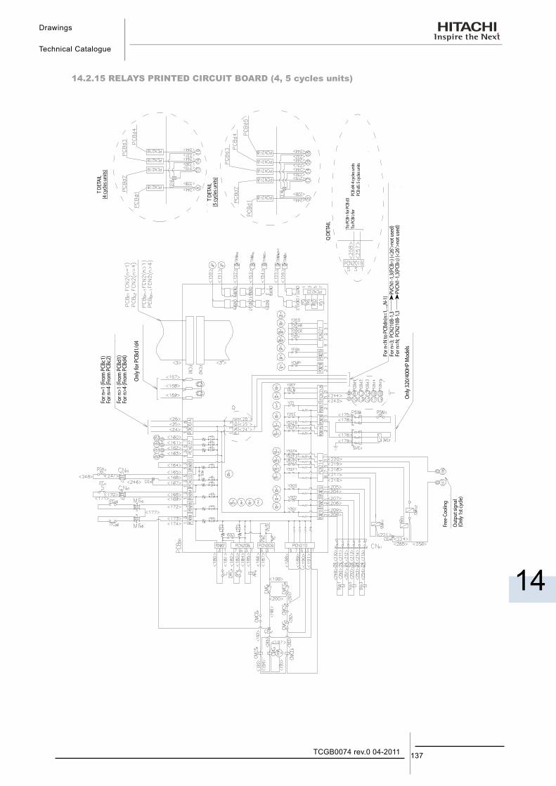
Drawings
Technical Catalogue
14
137TCGB0074 rev.0 04-2011
14.2.15 RELAYS PRINTED CIRCUIT BOARD (4, 5 cycles units)
Free
-Coo
ling
Out
put s
igna
l(O
nly
1st c
ycle
)
Onl
y 32
0/40
0HP
Mod
els
T DE
TAIL
(4 cy
cles u
nits
)
T DE
TAIL
(5 cy
cles u
nits
)
Q D
ETAI
L
To PC
BF1 f
or PC
B d3
To PC
BF2 f
or
P
CB d
4: 4 c
ycles
uni
ts
P
CB d
5: 5 c
ycles
uni
ts
For n
=3; P
CN21
0B-1
,3
PVCN
1-1,
3(PC
BF1)
(<26
’>no
t use
d)Fo
r n<N
to P
CBdn
(n=1
, ...,N
-1)
For n
=N; P
CN21
0B-1
,3
PVCN
1-1,
3(PC
BF2)
(<26
’>no
t use
d)
Onl
y 320
/400
HP M
odel
s
Onl
y for
PCB
d1/d
4
For n
=1 (F
rom
PCB
c1)
For n
=4 (F
rom
PCB
c2)
For n
>1 (F
rom
PCB
d1)
For n
>4 (F
rom
PCB
d4)
Out
put s
igna
l(O
nly 1
st cy
cle)
Free
-Coo
ling
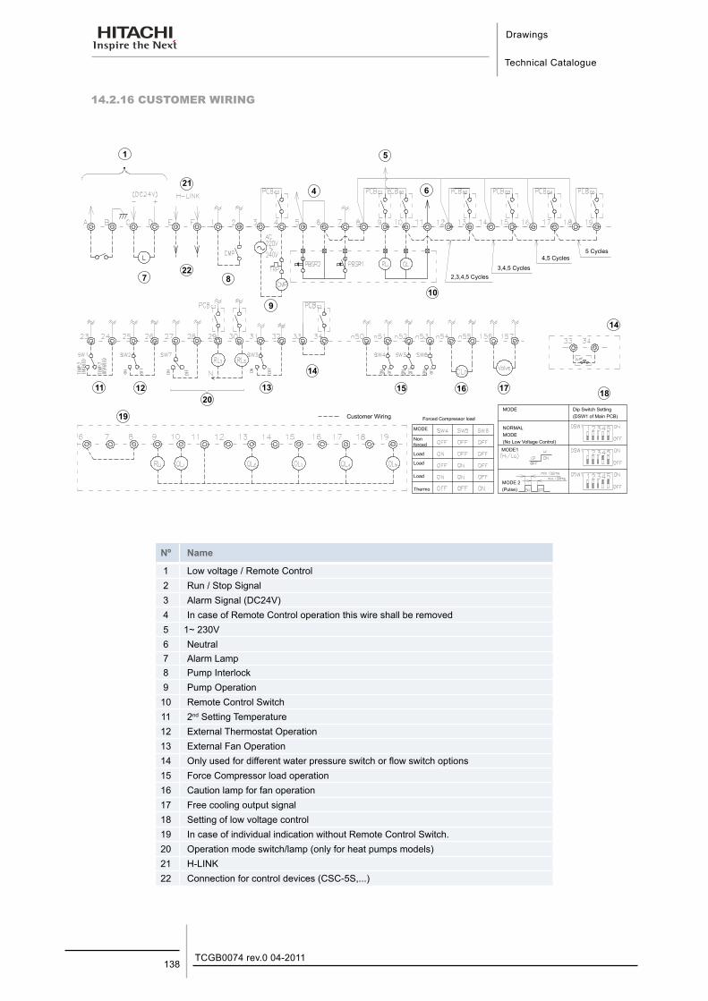
Drawings
Technical Catalogue
TCGB0074 rev.0 04-2011138
14.2.16 CUSTOMER WIRING
1
21
4
5
6
722
9
8
10
11 12
20
13
14
15 16 17
14
18
19
Nº Name
1 Low voltage / Remote Control2 Run / Stop Signal3 Alarm Signal (DC24V)4 In case of Remote Control operation this wire shall be removed5 1~ 230V6 Neutral 7 Alarm Lamp8 Pump Interlock9 Pump Operation10 Remote Control Switch11 2nd Setting Temperature12 External Thermostat Operation13 External Fan Operation14 Only used for different water pressure switch or flow switch options15 Force Compressor load operation16 Caution lamp for fan operation17 Free cooling output signal18 Setting of low voltage control19 In case of individual indication without Remote Control Switch.20 Operation mode switch/lamp (only for heat pumps models)21 H-LINK22 Connection for control devices (CSC-5S,...)
Customer WiringMODE Dip Switch Setting
(DSW1 of Main PCB)
NORMALMODE(No Low Voltage Control)MODE1
MODE 2(Pulse)
2,3,4,5 Cycles
5 Cycles4,5 Cycles
3,4,5 Cycles
MODE
Non forced
Load
Load
Load
Thermo
Forced Compressor load
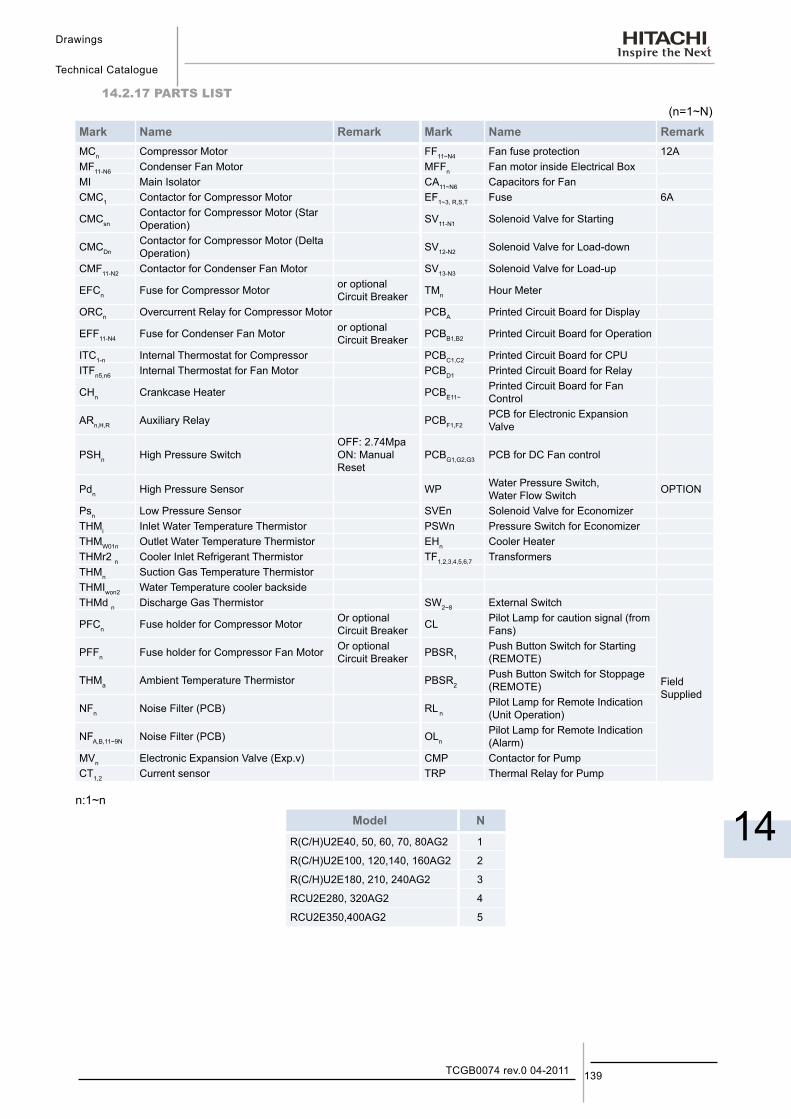
Drawings
Technical Catalogue
14
139TCGB0074 rev.0 04-2011
14.2.17 PARTS LIST(n=1~N)
Mark Name Remark Mark Name RemarkMCn Compressor Motor FF11~N4 Fan fuse protection 12AMF11-N6 Condenser Fan Motor MFFn Fan motor inside Electrical BoxMI Main Isolator CA11~N6 Capacitors for FanCMC1 Contactor for Compressor Motor EF1~3, R,S,T Fuse 6A
CMCsnContactor for Compressor Motor (Star Operation) SV11-N1 Solenoid Valve for Starting
CMCDnContactor for Compressor Motor (Delta Operation) SV12-N2 Solenoid Valve for Load-down
CMF11-N2 Contactor for Condenser Fan Motor SV13-N3 Solenoid Valve for Load-up
EFCn Fuse for Compressor Motor or optional Circuit Breaker TMn Hour Meter
ORCn Overcurrent Relay for Compressor Motor PCBA Printed Circuit Board for Display
EFF11-N4 Fuse for Condenser Fan Motor or optional Circuit Breaker PCBB1,B2 Printed Circuit Board for Operation
ITC1-n Internal Thermostat for Compressor PCBC1,C2 Printed Circuit Board for CPUITFn5,n6 Internal Thermostat for Fan Motor PCBD1 Printed Circuit Board for Relay
CHn Crankcase Heater PCBE11~Printed Circuit Board for Fan Control
ARn,H,R Auxiliary Relay PCBF1,F2PCB for Electronic Expansion Valve
PSHn High Pressure SwitchOFF: 2.74Mpa ON: Manual Reset
PCBG1,G2,G3 PCB for DC Fan control
Pdn High Pressure Sensor WP Water Pressure Switch, Water Flow Switch OPTION
Psn Low Pressure Sensor SVEn Solenoid Valve for EconomizerTHMi Inlet Water Temperature Thermistor PSWn Pressure Switch for EconomizerTHMW01n Outlet Water Temperature Thermistor EHn Cooler HeaterTHMr2 n Cooler Inlet Refrigerant Thermistor TF1,2,3,4,5,6,7 TransformersTHMn Suction Gas Temperature ThermistorTHMIwon2 Water Temperature cooler backsideTHMd n Discharge Gas Thermistor SW2~8 External Switch
Field Supplied
PFCn Fuse holder for Compressor Motor Or optional Circuit Breaker CL Pilot Lamp for caution signal (from
Fans)
PFFn Fuse holder for Compressor Fan Motor Or optional Circuit Breaker PBSR1
Push Button Switch for Starting (REMOTE)
THMa Ambient Temperature Thermistor PBSR2Push Button Switch for Stoppage (REMOTE)
NFn Noise Filter (PCB) RL nPilot Lamp for Remote Indication (Unit Operation)
NFA,B,11~9N Noise Filter (PCB) OLnPilot Lamp for Remote Indication (Alarm)
MVn Electronic Expansion Valve (Exp.v) CMP Contactor for PumpCT1,2 Current sensor TRP Thermal Relay for Pump
n:1~n
Model N
R(C/H)U2E40, 50, 60, 70, 80AG2 1
R(C/H)U2E100, 120,140, 160AG2 2
R(C/H)U2E180, 210, 240AG2 3
RCU2E280, 320AG2 4
RCU2E350,400AG2 5

Model Selection
Technical Catalogue
15
15. M o d e l S e l e c t i o n
141TCGB0074 rev.0 04-2011
Contents
15. Model Selection .......................................................................................................14115.1. Selection Example ............................................................................................................................... 142
15.2. Performance Table (RCU2E-AG2) ...................................................................................................... 143Performance Table (cont.) ....................................................................................................................................... 144Performance Table (cont.) ....................................................................................................................................... 145Performance Table (cont.) ....................................................................................................................................... 146
15.3. Performance Table (RHU2E-AG2) (Cooling Operation) ...................................................................... 147Performance Table (cont.) ....................................................................................................................................... 148Performance Table (cont.) ....................................................................................................................................... 149
15.4. Performance Table (RHU2E-AG2) (Heating Operation) ...................................................................... 150Performance Table (cont.) ....................................................................................................................................... 151Performance Table (cont.) ....................................................................................................................................... 152
15.5. Electrical Data .................................................................................................................................... 153
15.6. Sound Data.......................................................................................................................................... 155
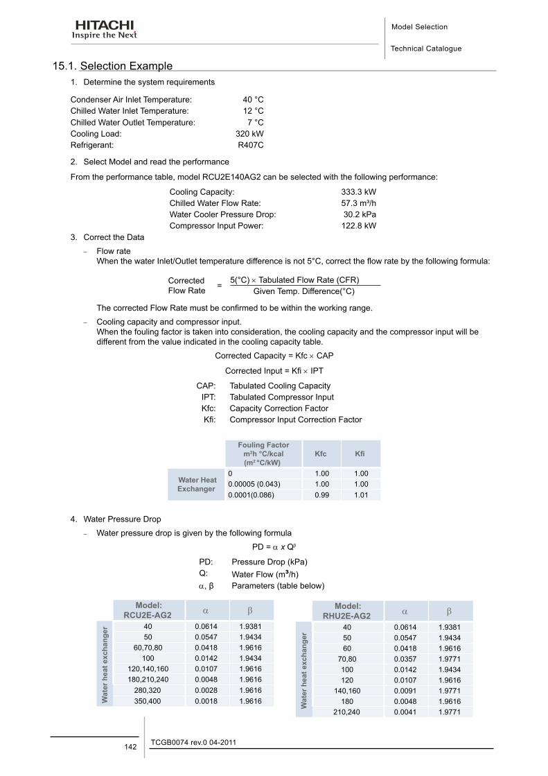
Model Selection
Technical Catalogue
TCGB0074 rev.0 04-2011142
15.1. Selection Example1. Determine the system requirements
Condenser Air Inlet Temperature: 40 °CChilled Water Inlet Temperature: 12 °CChilled Water Outlet Temperature: 7 °CCooling Load: 320 kWRefrigerant: R407C
2. Select Model and read the performance
From the performance table, model RCU2E140AG2 can be selected with the following performance:
Cooling Capacity: 333.3 kWChilled Water Flow Rate: 57.3 m³/hWater Cooler Pressure Drop: 30.2 kPaCompressor Input Power: 122.8 kW
3. Correct the Data
− Flow rate When the water Inlet/Outlet temperature difference is not 5°C, correct the flow rate by the following formula:
Corrected Flow Rate =
5(°C) × Tabulated Flow Rate (CFR)Given Temp. Difference(°C)
The corrected Flow Rate must be confirmed to be within the working range.
− Cooling capacity and compressor input. When the fouling factor is taken into consideration, the cooling capacity and the compressor input will be different from the value indicated in the cooling capacity table.
Corrected Capacity = Kfc × CAP
Corrected Input = Kfi × IPT
CAP: Tabulated Cooling CapacityIPT: Tabulated Compressor InputKfc: Capacity Correction FactorKfi: Compressor Input Correction Factor
Fouling Factor m2h °C/kcal(m2 °C/kW)
Kfc Kfi
Water Heat Exchanger
0 1.00 1.000.00005 (0.043) 1.00 1.000.0001(0.086) 0.99 1.01
4. Water Pressure Drop
− Water pressure drop is given by the following formula
PD = α x Qβ
PD: Pressure Drop (kPa)Q: Water Flow (m³/h)α, β Parameters (table below)
Model: RCU2E-AG2 α β
Wat
er h
eat e
xcha
nger 40 0.0614 1.938150 0.0547 1.9434
60,70,80 0.0418 1.9616100 0.0142 1.9434
120,140,160 0.0107 1.9616180,210,240 0.0048 1.9616
280,320 0.0028 1.9616350,400 0.0018 1.9616
Model: RHU2E-AG2 α β
Wat
er h
eat e
xcha
nger
40 0.0614 1.938150 0.0547 1.943460 0.0418 1.9616
70,80 0.0357 1.9771100 0.0142 1.9434120 0.0107 1.9616
140,160 0.0091 1.9771180 0.0048 1.9616
210,240 0.0041 1.9771
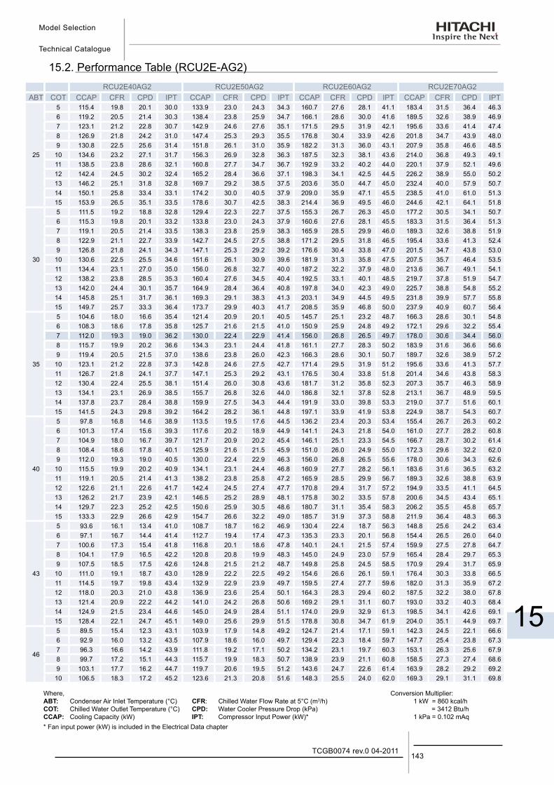
Model Selection
Technical Catalogue
15
143TCGB0074 rev.0 04-2011
15.2. Performance Table (RCU2E-AG2)RCU2E40AG2 RCU2E50AG2 RCU2E60AG2 RCU2E70AG2
ABT COT CCAP CFR CPD IPT CCAP CFR CPD IPT CCAP CFR CPD IPT CCAP CFR CPD IPT
25
5 115.4 19.8 20.1 30.0 133.9 23.0 24.3 34.3 160.7 27.6 28.1 41.1 183.4 31.5 36.4 46.3 6 119.2 20.5 21.4 30.3 138.4 23.8 25.9 34.7 166.1 28.6 30.0 41.6 189.5 32.6 38.9 46.9 7 123.1 21.2 22.8 30.7 142.9 24.6 27.6 35.1 171.5 29.5 31.9 42.1 195.6 33.6 41.4 47.4 8 126.9 21.8 24.2 31.0 147.4 25.3 29.3 35.5 176.8 30.4 33.9 42.6 201.8 34.7 43.9 48.0 9 130.8 22.5 25.6 31.4 151.8 26.1 31.0 35.9 182.2 31.3 36.0 43.1 207.9 35.8 46.6 48.5
10 134.6 23.2 27.1 31.7 156.3 26.9 32.8 36.3 187.5 32.3 38.1 43.6 214.0 36.8 49.3 49.1 11 138.5 23.8 28.6 32.1 160.8 27.7 34.7 36.7 192.9 33.2 40.2 44.0 220.1 37.9 52.1 49.6 12 142.4 24.5 30.2 32.4 165.2 28.4 36.6 37.1 198.3 34.1 42.5 44.5 226.2 38.9 55.0 50.2 13 146.2 25.1 31.8 32.8 169.7 29.2 38.5 37.5 203.6 35.0 44.7 45.0 232.4 40.0 57.9 50.7 14 150.1 25.8 33.4 33.1 174.2 30.0 40.5 37.9 209.0 35.9 47.1 45.5 238.5 41.0 61.0 51.3 15 153.9 26.5 35.1 33.5 178.6 30.7 42.5 38.3 214.4 36.9 49.5 46.0 244.6 42.1 64.1 51.8
30
5 111.5 19.2 18.8 32.8 129.4 22.3 22.7 37.5 155.3 26.7 26.3 45.0 177.2 30.5 34.1 50.7 6 115.3 19.8 20.1 33.2 133.8 23.0 24.3 37.9 160.6 27.6 28.1 45.5 183.3 31.5 36.4 51.3 7 119.1 20.5 21.4 33.5 138.3 23.8 25.9 38.3 165.9 28.5 29.9 46.0 189.3 32.6 38.8 51.9 8 122.9 21.1 22.7 33.9 142.7 24.5 27.5 38.8 171.2 29.5 31.8 46.5 195.4 33.6 41.3 52.4 9 126.8 21.8 24.1 34.3 147.1 25.3 29.2 39.2 176.6 30.4 33.8 47.0 201.5 34.7 43.8 53.0
10 130.6 22.5 25.5 34.6 151.6 26.1 30.9 39.6 181.9 31.3 35.8 47.5 207.5 35.7 46.4 53.5 11 134.4 23.1 27.0 35.0 156.0 26.8 32.7 40.0 187.2 32.2 37.9 48.0 213.6 36.7 49.1 54.1 12 138.2 23.8 28.5 35.3 160.4 27.6 34.5 40.4 192.5 33.1 40.1 48.5 219.7 37.8 51.9 54.7 13 142.0 24.4 30.1 35.7 164.9 28.4 36.4 40.8 197.8 34.0 42.3 49.0 225.7 38.8 54.8 55.2 14 145.8 25.1 31.7 36.1 169.3 29.1 38.3 41.3 203.1 34.9 44.5 49.5 231.8 39.9 57.7 55.8 15 149.7 25.7 33.3 36.4 173.7 29.9 40.3 41.7 208.5 35.9 46.8 50.0 237.9 40.9 60.7 56.4
35
5 104.6 18.0 16.6 35.4 121.4 20.9 20.1 40.5 145.7 25.1 23.2 48.7 166.3 28.6 30.1 54.8 6 108.3 18.6 17.8 35.8 125.7 21.6 21.5 41.0 150.9 25.9 24.8 49.2 172.1 29.6 32.2 55.4 7 112.0 19.3 19.0 36.2 130.0 22.4 22.9 41.4 156.0 26.8 26.5 49.7 178.0 30.6 34.4 56.0 8 115.7 19.9 20.2 36.6 134.3 23.1 24.4 41.8 161.1 27.7 28.3 50.2 183.9 31.6 36.6 56.6 9 119.4 20.5 21.5 37.0 138.6 23.8 26.0 42.3 166.3 28.6 30.1 50.7 189.7 32.6 38.9 57.2
10 123.1 21.2 22.8 37.3 142.8 24.6 27.5 42.7 171.4 29.5 31.9 51.2 195.6 33.6 41.3 57.7 11 126.7 21.8 24.1 37.7 147.1 25.3 29.2 43.1 176.5 30.4 33.8 51.8 201.4 34.6 43.8 58.3 12 130.4 22.4 25.5 38.1 151.4 26.0 30.8 43.6 181.7 31.2 35.8 52.3 207.3 35.7 46.3 58.9 13 134.1 23.1 26.9 38.5 155.7 26.8 32.6 44.0 186.8 32.1 37.8 52.8 213.1 36.7 48.9 59.5 14 137.8 23.7 28.4 38.8 159.9 27.5 34.3 44.4 191.9 33.0 39.8 53.3 219.0 37.7 51.6 60.1 15 141.5 24.3 29.8 39.2 164.2 28.2 36.1 44.8 197.1 33.9 41.9 53.8 224.9 38.7 54.3 60.7
40
5 97.8 16.8 14.6 38.9 113.5 19.5 17.6 44.5 136.2 23.4 20.3 53.4 155.4 26.7 26.3 60.2 6 101.3 17.4 15.6 39.3 117.6 20.2 18.9 44.9 141.1 24.3 21.8 54.0 161.0 27.7 28.2 60.8 7 104.9 18.0 16.7 39.7 121.7 20.9 20.2 45.4 146.1 25.1 23.3 54.5 166.7 28.7 30.2 61.4 8 108.4 18.6 17.8 40.1 125.9 21.6 21.5 45.9 151.0 26.0 24.9 55.0 172.3 29.6 32.2 62.0 9 112.0 19.3 19.0 40.5 130.0 22.4 22.9 46.3 156.0 26.8 26.5 55.6 178.0 30.6 34.3 62.6
10 115.5 19.9 20.2 40.9 134.1 23.1 24.4 46.8 160.9 27.7 28.2 56.1 183.6 31.6 36.5 63.2 11 119.1 20.5 21.4 41.3 138.2 23.8 25.8 47.2 165.9 28.5 29.9 56.7 189.3 32.6 38.8 63.9 12 122.6 21.1 22.6 41.7 142.4 24.5 27.4 47.7 170.8 29.4 31.7 57.2 194.9 33.5 41.1 64.5 13 126.2 21.7 23.9 42.1 146.5 25.2 28.9 48.1 175.8 30.2 33.5 57.8 200.6 34.5 43.4 65.1 14 129.7 22.3 25.2 42.5 150.6 25.9 30.5 48.6 180.7 31.1 35.4 58.3 206.2 35.5 45.8 65.7 15 133.3 22.9 26.6 42.9 154.7 26.6 32.2 49.0 185.7 31.9 37.3 58.8 211.9 36.4 48.3 66.3
43
5 93.6 16.1 13.4 41.0 108.7 18.7 16.2 46.9 130.4 22.4 18.7 56.3 148.8 25.6 24.2 63.4 6 97.1 16.7 14.4 41.4 112.7 19.4 17.4 47.3 135.3 23.3 20.1 56.8 154.4 26.5 26.0 64.0 7 100.6 17.3 15.4 41.8 116.8 20.1 18.6 47.8 140.1 24.1 21.5 57.4 159.9 27.5 27.8 64.7 8 104.1 17.9 16.5 42.2 120.8 20.8 19.9 48.3 145.0 24.9 23.0 57.9 165.4 28.4 29.7 65.3 9 107.5 18.5 17.5 42.6 124.8 21.5 21.2 48.7 149.8 25.8 24.5 58.5 170.9 29.4 31.7 65.9
10 111.0 19.1 18.7 43.0 128.9 22.2 22.5 49.2 154.6 26.6 26.1 59.1 176.4 30.3 33.8 66.5 11 114.5 19.7 19.8 43.4 132.9 22.9 23.9 49.7 159.5 27.4 27.7 59.6 182.0 31.3 35.9 67.2 12 118.0 20.3 21.0 43.8 136.9 23.6 25.4 50.1 164.3 28.3 29.4 60.2 187.5 32.2 38.0 67.8 13 121.4 20.9 22.2 44.2 141.0 24.2 26.8 50.6 169.2 29.1 31.1 60.7 193.0 33.2 40.3 68.4 14 124.9 21.5 23.4 44.6 145.0 24.9 28.4 51.1 174.0 29.9 32.9 61.3 198.5 34.1 42.6 69.1 15 128.4 22.1 24.7 45.1 149.0 25.6 29.9 51.5 178.8 30.8 34.7 61.9 204.0 35.1 44.9 69.7
46
5 89.5 15.4 12.3 43.1 103.9 17.9 14.8 49.2 124.7 21.4 17.1 59.1 142.3 24.5 22.1 66.6 6 92.9 16.0 13.2 43.5 107.9 18.6 16.0 49.7 129.4 22.3 18.4 59.7 147.7 25.4 23.8 67.3 7 96.3 16.6 14.2 43.9 111.8 19.2 17.1 50.2 134.2 23.1 19.7 60.3 153.1 26.3 25.6 67.9 8 99.7 17.2 15.1 44.3 115.7 19.9 18.3 50.7 138.9 23.9 21.1 60.8 158.5 27.3 27.4 68.6 9 103.1 17.7 16.2 44.7 119.7 20.6 19.5 51.2 143.6 24.7 22.6 61.4 163.9 28.2 29.2 69.2 10 106.5 18.3 17.2 45.2 123.6 21.3 20.8 51.6 148.3 25.5 24.0 62.0 169.3 29.1 31.1 69.8
Where,ABT: Condenser Air Inlet Temperature (°C)COT: Chilled Water Outlet Temperature (°C)CCAP: Cooling Capacity (kW)
CFR: Chilled Water Flow Rate at 5°C (m3/h)CPD: Water Cooler Pressure Drop (kPa)IPT: Compressor Input Power (kW)*
Conversion Multiplier:1 kW = 860 kcal/h = 3412 Btu/h1 kPa = 0.102 mAq
* Fan input power (kW) is included in the Electrical Data chapter
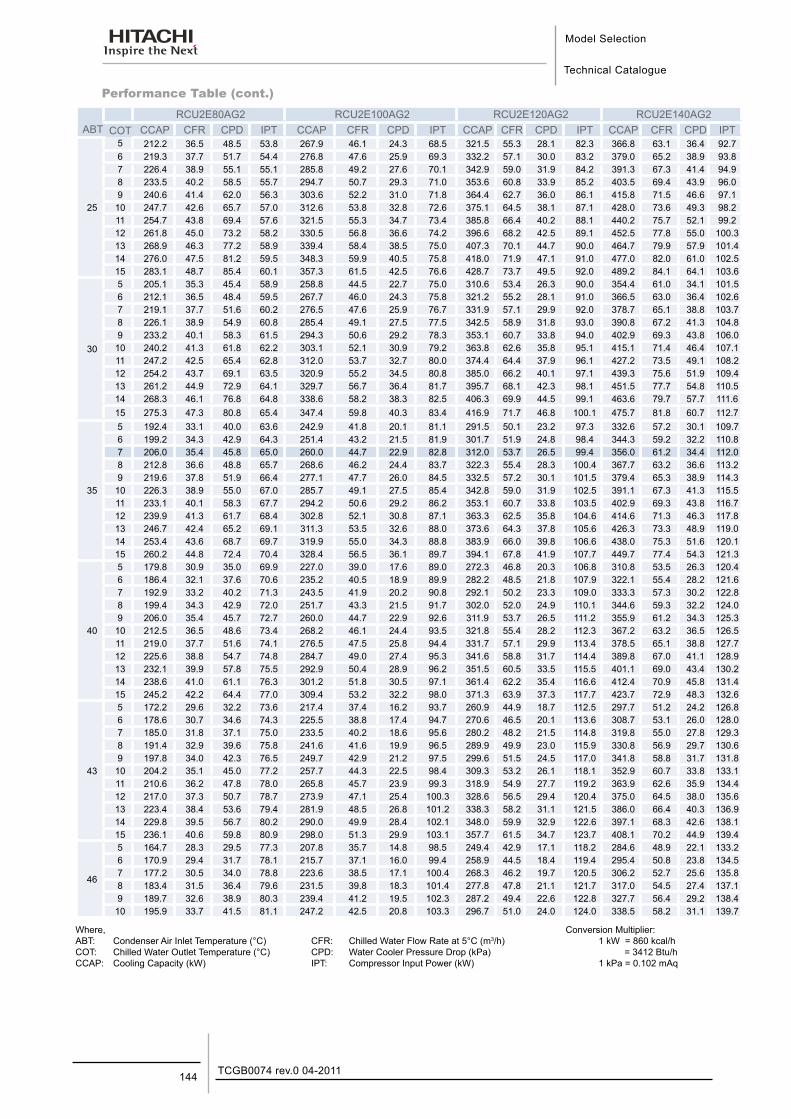
Model Selection
Technical Catalogue
TCGB0074 rev.0 04-2011144
Performance Table (cont.)
Where,ABT: Condenser Air Inlet Temperature (°C)COT: Chilled Water Outlet Temperature (°C)CCAP: Cooling Capacity (kW)
CFR: Chilled Water Flow Rate at 5°C (m3/h)CPD: Water Cooler Pressure Drop (kPa)IPT: Compressor Input Power (kW)
Conversion Multiplier:1 kW = 860 kcal/h = 3412 Btu/h1 kPa = 0.102 mAq
RCU2E80AG2 RCU2E100AG2 RCU2E120AG2 RCU2E140AG2ABT COT CCAP CFR CPD IPT CCAP CFR CPD IPT CCAP CFR CPD IPT CCAP CFR CPD IPT
25
5 212.2 36.5 48.5 53.8 267.9 46.1 24.3 68.5 321.5 55.3 28.1 82.3 366.8 63.1 36.4 92.7 6 219.3 37.7 51.7 54.4 276.8 47.6 25.9 69.3 332.2 57.1 30.0 83.2 379.0 65.2 38.9 93.8 7 226.4 38.9 55.1 55.1 285.8 49.2 27.6 70.1 342.9 59.0 31.9 84.2 391.3 67.3 41.4 94.9 8 233.5 40.2 58.5 55.7 294.7 50.7 29.3 71.0 353.6 60.8 33.9 85.2 403.5 69.4 43.9 96.0 9 240.6 41.4 62.0 56.3 303.6 52.2 31.0 71.8 364.4 62.7 36.0 86.1 415.8 71.5 46.6 97.1
10 247.7 42.6 65.7 57.0 312.6 53.8 32.8 72.6 375.1 64.5 38.1 87.1 428.0 73.6 49.3 98.2 11 254.7 43.8 69.4 57.6 321.5 55.3 34.7 73.4 385.8 66.4 40.2 88.1 440.2 75.7 52.1 99.2 12 261.8 45.0 73.2 58.2 330.5 56.8 36.6 74.2 396.6 68.2 42.5 89.1 452.5 77.8 55.0 100.3 13 268.9 46.3 77.2 58.9 339.4 58.4 38.5 75.0 407.3 70.1 44.7 90.0 464.7 79.9 57.9 101.4 14 276.0 47.5 81.2 59.5 348.3 59.9 40.5 75.8 418.0 71.9 47.1 91.0 477.0 82.0 61.0 102.5 15 283.1 48.7 85.4 60.1 357.3 61.5 42.5 76.6 428.7 73.7 49.5 92.0 489.2 84.1 64.1 103.6
30
5 205.1 35.3 45.4 58.9 258.8 44.5 22.7 75.0 310.6 53.4 26.3 90.0 354.4 61.0 34.1 101.5 6 212.1 36.5 48.4 59.5 267.7 46.0 24.3 75.8 321.2 55.2 28.1 91.0 366.5 63.0 36.4 102.6 7 219.1 37.7 51.6 60.2 276.5 47.6 25.9 76.7 331.9 57.1 29.9 92.0 378.7 65.1 38.8 103.7 8 226.1 38.9 54.9 60.8 285.4 49.1 27.5 77.5 342.5 58.9 31.8 93.0 390.8 67.2 41.3 104.8 9 233.2 40.1 58.3 61.5 294.3 50.6 29.2 78.3 353.1 60.7 33.8 94.0 402.9 69.3 43.8 106.0 10 240.2 41.3 61.8 62.2 303.1 52.1 30.9 79.2 363.8 62.6 35.8 95.1 415.1 71.4 46.4 107.1 11 247.2 42.5 65.4 62.8 312.0 53.7 32.7 80.0 374.4 64.4 37.9 96.1 427.2 73.5 49.1 108.2 12 254.2 43.7 69.1 63.5 320.9 55.2 34.5 80.8 385.0 66.2 40.1 97.1 439.3 75.6 51.9 109.4 13 261.2 44.9 72.9 64.1 329.7 56.7 36.4 81.7 395.7 68.1 42.3 98.1 451.5 77.7 54.8 110.5 14 268.3 46.1 76.8 64.8 338.6 58.2 38.3 82.5 406.3 69.9 44.5 99.1 463.6 79.7 57.7 111.6 15 275.3 47.3 80.8 65.4 347.4 59.8 40.3 83.4 416.9 71.7 46.8 100.1 475.7 81.8 60.7 112.7
35
5 192.4 33.1 40.0 63.6 242.9 41.8 20.1 81.1 291.5 50.1 23.2 97.3 332.6 57.2 30.1 109.7 6 199.2 34.3 42.9 64.3 251.4 43.2 21.5 81.9 301.7 51.9 24.8 98.4 344.3 59.2 32.2 110.8 7 206.0 35.4 45.8 65.0 260.0 44.7 22.9 82.8 312.0 53.7 26.5 99.4 356.0 61.2 34.4 112.0 8 212.8 36.6 48.8 65.7 268.6 46.2 24.4 83.7 322.3 55.4 28.3 100.4 367.7 63.2 36.6 113.2 9 219.6 37.8 51.9 66.4 277.1 47.7 26.0 84.5 332.5 57.2 30.1 101.5 379.4 65.3 38.9 114.3 10 226.3 38.9 55.0 67.0 285.7 49.1 27.5 85.4 342.8 59.0 31.9 102.5 391.1 67.3 41.3 115.5 11 233.1 40.1 58.3 67.7 294.2 50.6 29.2 86.2 353.1 60.7 33.8 103.5 402.9 69.3 43.8 116.7 12 239.9 41.3 61.7 68.4 302.8 52.1 30.8 87.1 363.3 62.5 35.8 104.6 414.6 71.3 46.3 117.8 13 246.7 42.4 65.2 69.1 311.3 53.5 32.6 88.0 373.6 64.3 37.8 105.6 426.3 73.3 48.9 119.0 14 253.4 43.6 68.7 69.7 319.9 55.0 34.3 88.8 383.9 66.0 39.8 106.6 438.0 75.3 51.6 120.1 15 260.2 44.8 72.4 70.4 328.4 56.5 36.1 89.7 394.1 67.8 41.9 107.7 449.7 77.4 54.3 121.3
40
5 179.8 30.9 35.0 69.9 227.0 39.0 17.6 89.0 272.3 46.8 20.3 106.8 310.8 53.5 26.3 120.4 6 186.4 32.1 37.6 70.6 235.2 40.5 18.9 89.9 282.2 48.5 21.8 107.9 322.1 55.4 28.2 121.6 7 192.9 33.2 40.2 71.3 243.5 41.9 20.2 90.8 292.1 50.2 23.3 109.0 333.3 57.3 30.2 122.8 8 199.4 34.3 42.9 72.0 251.7 43.3 21.5 91.7 302.0 52.0 24.9 110.1 344.6 59.3 32.2 124.0 9 206.0 35.4 45.7 72.7 260.0 44.7 22.9 92.6 311.9 53.7 26.5 111.2 355.9 61.2 34.3 125.3
10 212.5 36.5 48.6 73.4 268.2 46.1 24.4 93.5 321.8 55.4 28.2 112.3 367.2 63.2 36.5 126.5 11 219.0 37.7 51.6 74.1 276.5 47.5 25.8 94.4 331.7 57.1 29.9 113.4 378.5 65.1 38.8 127.7 12 225.6 38.8 54.7 74.8 284.7 49.0 27.4 95.3 341.6 58.8 31.7 114.4 389.8 67.0 41.1 128.9 13 232.1 39.9 57.8 75.5 292.9 50.4 28.9 96.2 351.5 60.5 33.5 115.5 401.1 69.0 43.4 130.2 14 238.6 41.0 61.1 76.3 301.2 51.8 30.5 97.1 361.4 62.2 35.4 116.6 412.4 70.9 45.8 131.4 15 245.2 42.2 64.4 77.0 309.4 53.2 32.2 98.0 371.3 63.9 37.3 117.7 423.7 72.9 48.3 132.6
43
5 172.2 29.6 32.2 73.6 217.4 37.4 16.2 93.7 260.9 44.9 18.7 112.5 297.7 51.2 24.2 126.8 6 178.6 30.7 34.6 74.3 225.5 38.8 17.4 94.7 270.6 46.5 20.1 113.6 308.7 53.1 26.0 128.0 7 185.0 31.8 37.1 75.0 233.5 40.2 18.6 95.6 280.2 48.2 21.5 114.8 319.8 55.0 27.8 129.3 8 191.4 32.9 39.6 75.8 241.6 41.6 19.9 96.5 289.9 49.9 23.0 115.9 330.8 56.9 29.7 130.6 9 197.8 34.0 42.3 76.5 249.7 42.9 21.2 97.5 299.6 51.5 24.5 117.0 341.8 58.8 31.7 131.8
10 204.2 35.1 45.0 77.2 257.7 44.3 22.5 98.4 309.3 53.2 26.1 118.1 352.9 60.7 33.8 133.1 11 210.6 36.2 47.8 78.0 265.8 45.7 23.9 99.3 318.9 54.9 27.7 119.2 363.9 62.6 35.9 134.4 12 217.0 37.3 50.7 78.7 273.9 47.1 25.4 100.3 328.6 56.5 29.4 120.4 375.0 64.5 38.0 135.6 13 223.4 38.4 53.6 79.4 281.9 48.5 26.8 101.2 338.3 58.2 31.1 121.5 386.0 66.4 40.3 136.9 14 229.8 39.5 56.7 80.2 290.0 49.9 28.4 102.1 348.0 59.9 32.9 122.6 397.1 68.3 42.6 138.1 15 236.1 40.6 59.8 80.9 298.0 51.3 29.9 103.1 357.7 61.5 34.7 123.7 408.1 70.2 44.9 139.4
46
5 164.7 28.3 29.5 77.3 207.8 35.7 14.8 98.5 249.4 42.9 17.1 118.2 284.6 48.9 22.1 133.2 6 170.9 29.4 31.7 78.1 215.7 37.1 16.0 99.4 258.9 44.5 18.4 119.4 295.4 50.8 23.8 134.5 7 177.2 30.5 34.0 78.8 223.6 38.5 17.1 100.4 268.3 46.2 19.7 120.5 306.2 52.7 25.6 135.8 8 183.4 31.5 36.4 79.6 231.5 39.8 18.3 101.4 277.8 47.8 21.1 121.7 317.0 54.5 27.4 137.1 9 189.7 32.6 38.9 80.3 239.4 41.2 19.5 102.3 287.2 49.4 22.6 122.8 327.7 56.4 29.2 138.4
10 195.9 33.7 41.5 81.1 247.2 42.5 20.8 103.3 296.7 51.0 24.0 124.0 338.5 58.2 31.1 139.7
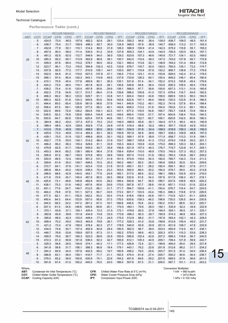
Model Selection
Technical Catalogue
15
145TCGB0074 rev.0 04-2011
Performance Table (cont.)
Where,ABT: Condenser Air Inlet Temperature (°C)COT: Chilled Water Outlet Temperature (°C)CCAP: Cooling Capacity (kW)
CFR: Chilled Water Flow Rate at 5°C (m3/h)CPD: Water Cooler Pressure Drop (kPa)IPT: Compressor Input Power (kW)
Conversion Multiplier:1 kW = 860 kcal/h = 3412 Btu/h1 kPa = 0.102 mAq
RCU2E160AG2 RCU2E180AG2 RCU2E210AG2 RCU2E240AG2ABT COT CCAP CFR CPD IPT CCAP CFR CPD IPT CCAP CFR CPD IPT CCAP CFR CPD IPT
25
5 424.5 73.0 48.5 107.6 482.2 82.9 28.1 123.4 550.2 94.6 36.4 139.0 636.7 109.5 48.5 161.4 6 438.7 75.4 51.7 108.9 498.3 85.7 30.0 124.9 568.5 97.8 38.9 140.7 658.0 113.2 51.7 163.3 7 452.8 77.9 55.1 110.1 514.4 88.5 31.9 126.3 586.9 100.9 41.4 142.3 679.2 116.8 55.1 165.2 8 467.0 80.3 58.5 111.4 530.5 91.2 33.9 127.8 605.3 104.1 43.9 144.0 700.5 120.5 58.5 167.1 9 481.2 82.8 62.0 112.7 546.6 94.0 36.0 129.2 623.6 107.3 46.6 145.6 721.7 124.1 62.0 169.0
10 495.3 85.2 65.7 113.9 562.6 96.8 38.1 130.7 642.0 110.4 49.3 147.2 743.0 127.8 65.7 170.9 11 509.5 87.6 69.4 115.2 578.7 99.5 40.2 132.1 660.4 113.6 52.1 148.9 764.2 131.4 69.4 172.8 12 523.7 90.1 73.2 116.5 594.8 102.3 42.5 133.6 678.7 116.7 55.0 150.5 785.5 135.1 73.2 174.7 13 537.8 92.5 77.2 117.7 610.9 105.1 44.7 135.0 697.1 119.9 57.9 152.2 806.7 138.8 77.2 176.6 14 552.0 94.9 81.2 119.0 627.0 107.8 47.1 136.5 715.4 123.1 61.0 153.8 828.0 142.4 81.2 178.5 15 566.1 97.4 85.4 120.3 643.1 110.6 49.5 137.9 733.8 126.2 64.1 155.4 849.2 146.1 85.4 180.4
30
5 410.1 70.5 45.4 117.8 465.9 80.1 26.3 135.1 531.6 91.4 34.1 152.2 615.2 105.8 45.4 176.6 6 424.2 73.0 48.4 119.1 481.8 82.9 28.1 136.6 549.8 94.6 36.4 153.9 636.3 109.4 48.4 178.6 7 438.2 75.4 51.6 120.4 497.8 85.6 29.9 138.1 568.0 97.7 38.8 155.6 657.3 113.1 51.6 180.6 8 452.3 77.8 54.9 121.7 513.7 88.4 31.8 139.6 586.2 100.8 41.3 157.3 678.4 116.7 54.9 182.5 9 466.3 80.2 58.3 123.0 529.7 91.1 33.8 141.1 604.4 104.0 43.8 159.0 699.5 120.3 58.3 184.5
10 480.3 82.6 61.8 124.3 545.6 93.8 35.8 142.6 622.6 107.1 46.4 160.6 720.5 123.9 61.8 186.5 11 494.4 85.0 65.4 125.6 561.6 96.6 37.9 144.1 640.8 110.2 49.1 162.3 741.6 127.6 65.4 188.4 12 508.4 87.5 69.1 126.9 577.5 99.3 40.1 145.6 659.0 113.3 51.9 164.0 762.6 131.2 69.1 190.4 13 522.5 89.9 72.9 128.2 593.5 102.1 42.3 147.1 677.2 116.5 54.8 165.7 783.7 134.8 72.9 192.4 14 536.5 92.3 76.8 129.6 609.4 104.8 44.5 148.6 695.4 119.6 57.7 167.4 804.8 138.4 76.8 194.3 15 550.6 94.7 80.8 130.9 625.4 107.6 46.8 150.1 713.6 122.7 60.7 169.1 825.8 142.0 80.8 196.3
35
5 384.9 66.2 40.0 127.3 437.2 75.2 23.2 146.0 498.9 85.8 30.1 164.5 577.3 99.3 40.0 190.9 6 398.4 68.5 42.9 128.6 452.6 77.8 24.8 147.6 516.4 88.8 32.2 166.3 597.7 102.8 42.9 193.0 7 412.0 70.9 45.8 130.0 468.0 80.5 26.5 149.1 534.0 91.8 34.4 168.0 618.0 106.3 45.8 195.0 8 425.6 73.2 48.8 131.4 483.4 83.1 28.3 150.6 551.6 94.9 36.6 169.7 638.3 109.8 48.8 197.0 9 439.1 75.5 51.9 132.7 498.8 85.8 30.1 152.2 569.1 97.9 38.9 171.5 658.7 113.3 51.9 199.1
10 452.7 77.9 55.0 134.1 514.2 88.4 31.9 153.7 586.7 100.9 41.3 173.2 679.0 116.8 55.0 201.1 11 466.2 80.2 58.3 135.4 529.6 91.1 33.8 155.3 604.3 103.9 43.8 175.0 699.3 120.3 58.3 203.1 12 479.8 82.5 61.7 136.8 545.0 93.7 35.8 156.8 621.9 107.0 46.3 176.7 719.7 123.8 61.7 205.1 13 493.3 84.9 65.2 138.1 560.4 96.4 37.8 158.4 639.4 110.0 48.9 178.5 740.0 127.3 65.2 207.2 14 506.9 87.2 68.7 139.5 575.8 99.0 39.8 159.9 657.0 113.0 51.6 180.2 760.3 130.8 68.7 209.2 15 520.5 89.5 72.4 140.8 591.2 101.7 41.9 161.5 674.6 116.0 54.3 182.0 780.7 134.3 72.4 211.2
40
5 359.6 61.9 35.0 139.7 408.5 70.3 20.3 160.2 466.1 80.2 26.3 180.6 539.5 92.8 35.0 209.6 6 372.7 64.1 37.6 141.1 423.4 72.8 21.8 161.9 483.1 83.1 28.2 182.4 559.1 96.2 37.6 211.7 7 385.8 66.4 40.2 142.6 438.2 75.4 23.3 163.5 500.0 86.0 30.2 184.2 578.7 99.5 40.2 213.8 8 398.9 68.6 42.9 144.0 453.1 77.9 24.9 165.1 517.0 88.9 32.2 186.1 598.3 102.9 42.9 216.0 9 411.9 70.9 45.7 145.4 467.9 80.5 26.5 166.8 533.9 91.8 34.3 187.9 617.9 106.3 45.7 218.1
10 425.0 73.1 48.6 146.8 482.8 83.0 28.2 168.4 550.8 94.7 36.5 189.7 637.5 109.6 48.6 220.2 11 438.1 75.3 51.6 148.2 497.6 85.6 29.9 170.0 567.8 97.7 38.8 191.6 657.1 113.0 51.6 222.4 12 451.1 77.6 54.7 149.7 512.5 88.1 31.7 171.7 584.7 100.6 41.1 193.4 676.7 116.4 54.7 224.5 13 464.2 79.8 57.8 151.1 527.3 90.7 33.5 173.3 601.7 103.5 43.4 195.3 696.3 119.8 57.8 226.6 14 477.3 82.1 61.1 152.5 542.2 93.3 35.4 174.9 618.6 106.4 45.8 197.1 715.9 123.1 61.1 228.8 15 490.4 84.3 64.4 153.9 557.0 95.8 37.3 176.5 635.6 109.3 48.3 198.9 735.5 126.5 64.4 230.9
43
5 344.5 59.3 32.2 147.2 391.3 67.3 18.7 168.8 446.5 76.8 24.2 190.2 516.7 88.9 32.2 220.7 6 357.3 61.5 34.6 148.6 405.8 69.8 20.1 170.5 463.1 79.6 26.0 192.1 535.9 92.2 34.6 222.9 7 370.1 63.6 37.1 150.1 420.4 72.3 21.5 172.1 479.6 82.5 27.8 194.0 555.1 95.5 37.1 225.1 8 382.8 65.8 39.6 151.6 434.9 74.8 23.0 173.8 496.2 85.3 29.7 195.9 574.3 98.8 39.6 227.3 9 395.6 68.0 42.3 153.0 449.4 77.3 24.5 175.5 512.8 88.2 31.7 197.8 593.4 102.1 42.3 229.5
10 408.4 70.2 45.0 154.5 463.9 79.8 26.1 177.2 529.3 91.0 33.8 199.6 612.6 105.4 45.0 231.7 11 421.2 72.4 47.8 156.0 478.4 82.3 27.7 178.9 545.9 93.9 35.9 201.5 631.8 108.7 47.8 233.9 12 434.0 74.6 50.7 157.4 492.9 84.8 29.4 180.5 562.5 96.7 38.0 203.4 650.9 112.0 50.7 236.1 13 446.7 76.8 53.6 158.9 507.5 87.3 31.1 182.2 579.0 99.6 40.3 205.3 670.1 115.3 53.6 238.3 14 459.5 79.0 56.7 160.3 522.0 89.8 32.9 183.9 595.6 102.4 42.6 207.2 689.3 118.6 56.7 240.5 15 472.3 81.2 59.8 161.8 536.5 92.3 34.7 185.6 612.1 105.3 44.9 209.1 708.4 121.9 59.8 242.7
46
5 329.3 56.6 29.5 154.6 374.1 64.3 17.1 177.3 426.9 73.4 22.1 199.8 494.0 85.0 29.5 231.9 6 341.8 58.8 31.7 156.1 388.3 66.8 18.4 179.1 443.1 76.2 23.8 201.8 512.8 88.2 31.7 234.2 7 354.3 60.9 34.0 157.6 402.5 69.2 19.7 180.8 459.2 79.0 25.6 203.7 531.5 91.4 34.0 236.4 8 366.8 63.1 36.4 159.1 416.7 71.7 21.1 182.5 475.4 81.8 27.4 205.7 550.2 94.6 36.4 238.7 9 379.3 65.2 38.9 160.6 430.9 74.1 22.6 184.2 491.6 84.6 29.2 207.6 569.0 97.9 38.9 241.0
10 391.8 67.4 41.5 162.2 445.0 76.5 24.0 186.0 507.8 87.3 31.1 209.5 587.7 101.1 41.5 243.2
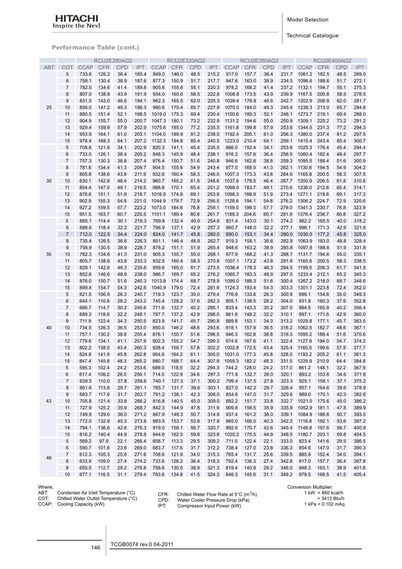
Model Selection
Technical Catalogue
TCGB0074 rev.0 04-2011146
Performance Table (cont.)
RCU2E280AG2 RCU2E320AG2 RCU2E350AG2 RCU2E400AG2ABT COT CCAP CFR CPD IPT CCAP CFR CPD IPT CCAP CFR CPD IPT CCAP CFR CPD IPT
25
5 733.6 126.2 36.4 185.4 849.0 146.0 48.5 215.2 917.0 157.7 36.4 231.7 1061.2 182.5 48.5 269.0 6 758.1 130.4 38.9 187.6 877.3 150.9 51.7 217.7 947.6 163.0 38.9 234.5 1096.6 188.6 51.7 272.1 7 782.5 134.6 41.4 189.8 905.6 155.8 55.1 220.3 978.2 168.2 41.4 237.2 1132.1 194.7 55.1 275.3 8 807.0 138.8 43.9 191.9 934.0 160.6 58.5 222.8 1008.8 173.5 43.9 239.9 1167.5 200.8 58.5 278.5 9 831.5 143.0 46.6 194.1 962.3 165.5 62.0 225.3 1039.4 178.8 46.6 242.7 1202.9 206.9 62.0 281.7
10 856.0 147.2 49.3 196.3 990.6 170.4 65.7 227.9 1070.0 184.0 49.3 245.4 1238.3 213.0 65.7 284.8 11 880.5 151.4 52.1 198.5 1019.0 175.3 69.4 230.4 1100.6 189.3 52.1 248.1 1273.7 219.1 69.4 288.0 12 904.9 155.7 55.0 200.7 1047.3 180.1 73.2 232.9 1131.2 194.6 55.0 250.9 1309.1 225.2 73.2 291.2 13 929.4 159.9 57.9 202.9 1075.6 185.0 77.2 235.5 1161.8 199.8 57.9 253.6 1344.5 231.3 77.2 294.3 14 953.9 164.1 61.0 205.1 1104.0 189.9 81.2 238.0 1192.4 205.1 61.0 256.3 1380.0 237.4 81.2 297.5 15 978.4 168.3 64.1 207.2 1132.3 194.8 85.4 240.5 1223.0 210.4 64.1 259.1 1415.4 243.4 85.4 300.7
30
5 708.8 121.9 34.1 202.9 820.3 141.1 45.4 235.5 886.0 152.4 34.1 253.6 1025.3 176.4 45.4 294.4 6 733.0 126.1 36.4 205.2 848.3 145.9 48.4 238.1 916.3 157.6 36.4 256.5 1060.4 182.4 48.4 297.7 7 757.3 130.3 38.8 207.4 876.4 150.7 51.6 240.8 946.6 162.8 38.8 259.3 1095.5 188.4 51.6 300.9 8 781.6 134.4 41.3 209.7 904.5 155.6 54.9 243.4 977.0 168.0 41.3 262.1 1130.6 194.5 54.9 304.2 9 805.8 138.6 43.8 211.9 932.6 160.4 58.3 246.0 1007.3 173.3 43.8 264.9 1165.8 200.5 58.3 307.5
10 830.1 142.8 46.4 214.2 960.7 165.2 61.8 248.6 1037.6 178.5 46.4 267.7 1200.9 206.5 61.8 310.8 11 854.4 147.0 49.1 216.5 988.8 170.1 65.4 251.2 1068.0 183.7 49.1 270.6 1236.0 212.6 65.4 314.1 12 878.6 151.1 51.9 218.7 1016.9 174.9 69.1 253.9 1098.3 188.9 51.9 273.4 1271.1 218.6 69.1 317.3 13 902.9 155.3 54.8 221.0 1044.9 179.7 72.9 256.5 1128.6 194.1 54.8 276.2 1306.2 224.7 72.9 320.6 14 927.2 159.5 57.7 223.2 1073.0 184.6 76.8 259.1 1159.0 199.3 57.7 279.0 1341.3 230.7 76.8 323.9 15 951.5 163.7 60.7 225.5 1101.1 189.4 80.8 261.7 1189.3 204.6 60.7 281.9 1376.4 236.7 80.8 327.2
35
5 665.1 114.4 30.1 219.3 769.8 132.4 40.0 254.6 831.4 143.0 30.1 274.2 962.2 165.5 40.0 318.2 6 688.6 118.4 32.2 221.7 796.9 137.1 42.9 257.3 860.7 148.0 32.2 277.1 996.1 171.3 42.9 321.6 7 712.0 122.5 34.4 224.0 824.0 141.7 45.8 260.0 890.0 153.1 34.4 280.0 1030.0 177.2 45.8 325.0 8 735.4 126.5 36.6 226.3 851.1 146.4 48.8 262.7 919.3 158.1 36.6 282.9 1063.9 183.0 48.8 328.4 9 758.9 130.5 38.9 228.7 878.2 151.1 51.9 265.4 948.6 163.2 38.9 285.8 1097.8 188.8 51.9 331.8
10 782.3 134.6 41.3 231.0 905.3 155.7 55.0 268.1 977.9 168.2 41.3 288.7 1131.7 194.6 55.0 335.1 11 805.7 138.6 43.8 233.3 932.5 160.4 58.3 270.8 1007.1 173.2 43.8 291.6 1165.6 200.5 58.3 338.5 12 829.1 142.6 46.3 235.6 959.6 165.0 61.7 273.5 1036.4 178.3 46.3 294.5 1199.5 206.3 61.7 341.9 13 852.6 146.6 48.9 238.0 986.7 169.7 65.2 276.2 1065.7 183.3 48.9 297.5 1233.4 212.1 65.2 345.3 14 876.0 150.7 51.6 240.3 1013.8 174.4 68.7 278.9 1095.0 188.3 51.6 300.4 1267.2 218.0 68.7 348.6 15 899.4 154.7 54.3 242.6 1040.9 179.0 72.4 281.6 1124.3 193.4 54.3 303.3 1301.1 223.8 72.4 352.0
40
5 621.5 106.9 26.3 240.7 719.3 123.7 35.0 279.4 776.9 133.6 26.3 300.9 899.1 154.6 35.0 349.3 6 644.1 110.8 28.2 243.2 745.4 128.2 37.6 282.3 805.1 138.5 28.2 304.0 931.8 160.3 37.6 352.8 7 666.7 114.7 30.2 245.6 771.6 132.7 40.2 285.1 833.4 143.3 30.2 307.0 964.5 165.9 40.2 356.4 8 689.3 118.6 32.2 248.1 797.7 137.2 42.9 288.0 861.6 148.2 32.2 310.1 997.1 171.5 42.9 360.0 9 711.9 122.4 34.3 250.5 823.9 141.7 45.7 290.8 889.8 153.1 34.3 313.2 1029.8 177.1 45.7 363.5
10 734.5 126.3 36.5 253.0 850.0 146.2 48.6 293.6 918.1 157.9 36.5 316.2 1062.5 182.7 48.6 367.1 11 757.1 130.2 38.8 255.4 876.1 150.7 51.6 296.5 946.3 162.8 38.8 319.3 1095.2 188.4 51.6 370.6 12 779.6 134.1 41.1 257.9 902.3 155.2 54.7 299.3 974.6 167.6 41.1 322.4 1127.9 194.0 54.7 374.2 13 802.2 138.0 43.4 260.3 928.4 159.7 57.8 302.2 1002.8 172.5 43.4 325.4 1160.5 199.6 57.8 377.7 14 824.8 141.9 45.8 262.8 954.6 164.2 61.1 305.0 1031.0 177.3 45.8 328.5 1193.2 205.2 61.1 381.3 15 847.4 145.8 48.3 265.2 980.7 168.7 64.4 307.9 1059.3 182.2 48.3 331.5 1225.9 210.9 64.4 384.8
43
5 595.3 102.4 24.2 253.6 689.0 118.5 32.2 294.3 744.2 128.0 24.2 317.0 861.2 148.1 32.2 367.9 6 617.4 106.2 26.0 256.1 714.5 122.9 34.6 297.3 771.8 132.7 26.0 320.1 893.2 153.6 34.6 371.6 7 639.5 110.0 27.8 258.6 740.1 127.3 37.1 300.2 799.4 137.5 27.8 323.3 925.1 159.1 37.1 375.2 8 661.6 113.8 29.7 261.1 765.7 131.7 39.6 303.1 827.0 142.2 29.7 326.4 957.1 164.6 39.6 378.9 9 683.7 117.6 31.7 263.7 791.2 136.1 42.3 306.0 854.6 147.0 31.7 329.6 989.0 170.1 42.3 382.6
10 705.8 121.4 33.8 266.2 816.8 140.5 45.0 309.0 882.2 151.7 33.8 332.7 1021.0 175.6 45.0 386.2 11 727.9 125.2 35.9 268.7 842.3 144.9 47.8 311.9 909.8 156.5 35.9 335.9 1052.9 181.1 47.8 389.9 12 749.9 129.0 38.0 271.2 867.9 149.3 50.7 314.8 937.4 161.2 38.0 339.1 1084.9 186.6 50.7 393.5 13 772.0 132.8 40.3 273.8 893.5 153.7 53.6 317.8 965.0 166.0 40.3 342.2 1116.8 192.1 53.6 397.2 14 794.1 136.6 42.6 276.3 919.0 158.1 56.7 320.7 992.6 170.7 42.6 345.4 1148.8 197.6 56.7 400.9 15 816.2 140.4 44.9 278.8 944.6 162.5 59.8 323.6 1020.2 175.5 44.9 348.5 1180.7 203.1 59.8 404.5
46
5 569.2 97.9 22.1 266.4 658.7 113.3 29.5 309.2 711.5 122.4 22.1 333.0 823.4 141.6 29.5 386.5 6 590.7 101.6 23.8 269.0 683.7 117.6 31.7 312.2 738.4 127.0 23.8 336.3 854.6 147.0 31.7 390.3 7 612.3 105.3 25.6 271.6 708.6 121.9 34.0 315.3 765.4 131.7 25.6 339.5 885.8 152.4 34.0 394.1 8 633.9 109.0 27.4 274.2 733.6 126.2 36.4 318.3 792.4 136.3 27.4 342.8 917.0 157.7 36.4 397.8 9 655.5 112.7 29.2 276.8 758.6 130.5 38.9 321.3 819.4 140.9 29.2 346.0 948.3 163.1 38.9 401.6
10 677.1 116.5 31.1 279.4 783.6 134.8 41.5 324.3 846.3 145.6 31.1 349.2 979.5 168.5 41.5 405.4
Where,ABT: Condenser Air Inlet Temperature (°C)COT: Chilled Water Outlet Temperature (°C)CCAP: Cooling Capacity (kW)
CFR: Chilled Water Flow Rate at 5°C (m3/h)CPD: Water Cooler Pressure Drop (kPa)IPT: Compressor Input Power (kW)
Conversion Multiplier:1 kW = 860 kcal/h = 3412 Btu/h1 kPa = 0.102 mAq
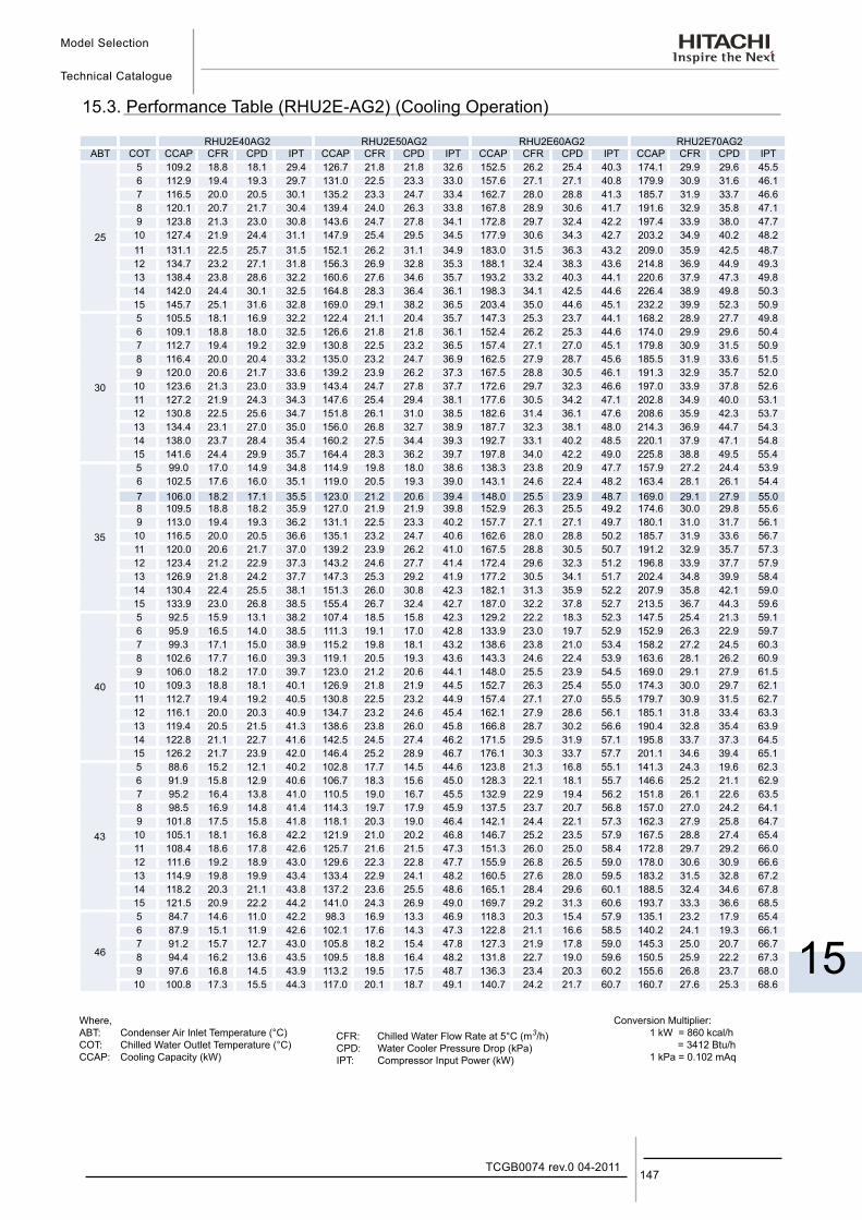
Model Selection
Technical Catalogue
15
147TCGB0074 rev.0 04-2011
15.3. Performance Table (RHU2E-AG2) (Cooling Operation)
RHU2E40AG2 RHU2E50AG2 RHU2E60AG2 RHU2E70AG2ABT COT CCAP CFR CPD IPT CCAP CFR CPD IPT CCAP CFR CPD IPT CCAP CFR CPD IPT
25
5 109.2 18.8 18.1 29.4 126.7 21.8 21.8 32.6 152.5 26.2 25.4 40.3 174.1 29.9 29.6 45.5 6 112.9 19.4 19.3 29.7 131.0 22.5 23.3 33.0 157.6 27.1 27.1 40.8 179.9 30.9 31.6 46.1 7 116.5 20.0 20.5 30.1 135.2 23.3 24.7 33.4 162.7 28.0 28.8 41.3 185.7 31.9 33.7 46.6 8 120.1 20.7 21.7 30.4 139.4 24.0 26.3 33.8 167.8 28.9 30.6 41.7 191.6 32.9 35.8 47.1 9 123.8 21.3 23.0 30.8 143.6 24.7 27.8 34.1 172.8 29.7 32.4 42.2 197.4 33.9 38.0 47.7
10 127.4 21.9 24.4 31.1 147.9 25.4 29.5 34.5 177.9 30.6 34.3 42.7 203.2 34.9 40.2 48.2 11 131.1 22.5 25.7 31.5 152.1 26.2 31.1 34.9 183.0 31.5 36.3 43.2 209.0 35.9 42.5 48.7 12 134.7 23.2 27.1 31.8 156.3 26.9 32.8 35.3 188.1 32.4 38.3 43.6 214.8 36.9 44.9 49.3 13 138.4 23.8 28.6 32.2 160.6 27.6 34.6 35.7 193.2 33.2 40.3 44.1 220.6 37.9 47.3 49.8 14 142.0 24.4 30.1 32.5 164.8 28.3 36.4 36.1 198.3 34.1 42.5 44.6 226.4 38.9 49.8 50.3 15 145.7 25.1 31.6 32.8 169.0 29.1 38.2 36.5 203.4 35.0 44.6 45.1 232.2 39.9 52.3 50.9
30
5 105.5 18.1 16.9 32.2 122.4 21.1 20.4 35.7 147.3 25.3 23.7 44.1 168.2 28.9 27.7 49.8 6 109.1 18.8 18.0 32.5 126.6 21.8 21.8 36.1 152.4 26.2 25.3 44.6 174.0 29.9 29.6 50.4 7 112.7 19.4 19.2 32.9 130.8 22.5 23.2 36.5 157.4 27.1 27.0 45.1 179.8 30.9 31.5 50.9 8 116.4 20.0 20.4 33.2 135.0 23.2 24.7 36.9 162.5 27.9 28.7 45.6 185.5 31.9 33.6 51.5 9 120.0 20.6 21.7 33.6 139.2 23.9 26.2 37.3 167.5 28.8 30.5 46.1 191.3 32.9 35.7 52.0
10 123.6 21.3 23.0 33.9 143.4 24.7 27.8 37.7 172.6 29.7 32.3 46.6 197.0 33.9 37.8 52.6 11 127.2 21.9 24.3 34.3 147.6 25.4 29.4 38.1 177.6 30.5 34.2 47.1 202.8 34.9 40.0 53.1 12 130.8 22.5 25.6 34.7 151.8 26.1 31.0 38.5 182.6 31.4 36.1 47.6 208.6 35.9 42.3 53.7 13 134.4 23.1 27.0 35.0 156.0 26.8 32.7 38.9 187.7 32.3 38.1 48.0 214.3 36.9 44.7 54.3 14 138.0 23.7 28.4 35.4 160.2 27.5 34.4 39.3 192.7 33.1 40.2 48.5 220.1 37.9 47.1 54.8 15 141.6 24.4 29.9 35.7 164.4 28.3 36.2 39.7 197.8 34.0 42.2 49.0 225.8 38.8 49.5 55.4
35
5 99.0 17.0 14.9 34.8 114.9 19.8 18.0 38.6 138.3 23.8 20.9 47.7 157.9 27.2 24.4 53.9 6 102.5 17.6 16.0 35.1 119.0 20.5 19.3 39.0 143.1 24.6 22.4 48.2 163.4 28.1 26.1 54.4 7 106.0 18.2 17.1 35.5 123.0 21.2 20.6 39.4 148.0 25.5 23.9 48.7 169.0 29.1 27.9 55.0 8 109.5 18.8 18.2 35.9 127.0 21.9 21.9 39.8 152.9 26.3 25.5 49.2 174.6 30.0 29.8 55.6 9 113.0 19.4 19.3 36.2 131.1 22.5 23.3 40.2 157.7 27.1 27.1 49.7 180.1 31.0 31.7 56.1
10 116.5 20.0 20.5 36.6 135.1 23.2 24.7 40.6 162.6 28.0 28.8 50.2 185.7 31.9 33.6 56.7 11 120.0 20.6 21.7 37.0 139.2 23.9 26.2 41.0 167.5 28.8 30.5 50.7 191.2 32.9 35.7 57.3 12 123.4 21.2 22.9 37.3 143.2 24.6 27.7 41.4 172.4 29.6 32.3 51.2 196.8 33.9 37.7 57.9 13 126.9 21.8 24.2 37.7 147.3 25.3 29.2 41.9 177.2 30.5 34.1 51.7 202.4 34.8 39.9 58.4 14 130.4 22.4 25.5 38.1 151.3 26.0 30.8 42.3 182.1 31.3 35.9 52.2 207.9 35.8 42.1 59.0 15 133.9 23.0 26.8 38.5 155.4 26.7 32.4 42.7 187.0 32.2 37.8 52.7 213.5 36.7 44.3 59.6
40
5 92.5 15.9 13.1 38.2 107.4 18.5 15.8 42.3 129.2 22.2 18.3 52.3 147.5 25.4 21.3 59.1 6 95.9 16.5 14.0 38.5 111.3 19.1 17.0 42.8 133.9 23.0 19.7 52.9 152.9 26.3 22.9 59.7 7 99.3 17.1 15.0 38.9 115.2 19.8 18.1 43.2 138.6 23.8 21.0 53.4 158.2 27.2 24.5 60.3 8 102.6 17.7 16.0 39.3 119.1 20.5 19.3 43.6 143.3 24.6 22.4 53.9 163.6 28.1 26.2 60.9 9 106.0 18.2 17.0 39.7 123.0 21.2 20.6 44.1 148.0 25.5 23.9 54.5 169.0 29.1 27.9 61.5
10 109.3 18.8 18.1 40.1 126.9 21.8 21.9 44.5 152.7 26.3 25.4 55.0 174.3 30.0 29.7 62.1 11 112.7 19.4 19.2 40.5 130.8 22.5 23.2 44.9 157.4 27.1 27.0 55.5 179.7 30.9 31.5 62.7 12 116.1 20.0 20.3 40.9 134.7 23.2 24.6 45.4 162.1 27.9 28.6 56.1 185.1 31.8 33.4 63.3 13 119.4 20.5 21.5 41.3 138.6 23.8 26.0 45.8 166.8 28.7 30.2 56.6 190.4 32.8 35.4 63.9 14 122.8 21.1 22.7 41.6 142.5 24.5 27.4 46.2 171.5 29.5 31.9 57.1 195.8 33.7 37.3 64.5 15 126.2 21.7 23.9 42.0 146.4 25.2 28.9 46.7 176.1 30.3 33.7 57.7 201.1 34.6 39.4 65.1
43
5 88.6 15.2 12.1 40.2 102.8 17.7 14.5 44.6 123.8 21.3 16.8 55.1 141.3 24.3 19.6 62.3 6 91.9 15.8 12.9 40.6 106.7 18.3 15.6 45.0 128.3 22.1 18.1 55.7 146.6 25.2 21.1 62.9 7 95.2 16.4 13.8 41.0 110.5 19.0 16.7 45.5 132.9 22.9 19.4 56.2 151.8 26.1 22.6 63.5 8 98.5 16.9 14.8 41.4 114.3 19.7 17.9 45.9 137.5 23.7 20.7 56.8 157.0 27.0 24.2 64.1 9 101.8 17.5 15.8 41.8 118.1 20.3 19.0 46.4 142.1 24.4 22.1 57.3 162.3 27.9 25.8 64.7
10 105.1 18.1 16.8 42.2 121.9 21.0 20.2 46.8 146.7 25.2 23.5 57.9 167.5 28.8 27.4 65.4 11 108.4 18.6 17.8 42.6 125.7 21.6 21.5 47.3 151.3 26.0 25.0 58.4 172.8 29.7 29.2 66.0 12 111.6 19.2 18.9 43.0 129.6 22.3 22.8 47.7 155.9 26.8 26.5 59.0 178.0 30.6 30.9 66.6 13 114.9 19.8 19.9 43.4 133.4 22.9 24.1 48.2 160.5 27.6 28.0 59.5 183.2 31.5 32.8 67.2 14 118.2 20.3 21.1 43.8 137.2 23.6 25.5 48.6 165.1 28.4 29.6 60.1 188.5 32.4 34.6 67.8 15 121.5 20.9 22.2 44.2 141.0 24.3 26.9 49.0 169.7 29.2 31.3 60.6 193.7 33.3 36.6 68.5
46
5 84.7 14.6 11.0 42.2 98.3 16.9 13.3 46.9 118.3 20.3 15.4 57.9 135.1 23.2 17.9 65.4 6 87.9 15.1 11.9 42.6 102.1 17.6 14.3 47.3 122.8 21.1 16.6 58.5 140.2 24.1 19.3 66.1 7 91.2 15.7 12.7 43.0 105.8 18.2 15.4 47.8 127.3 21.9 17.8 59.0 145.3 25.0 20.7 66.7 8 94.4 16.2 13.6 43.5 109.5 18.8 16.4 48.2 131.8 22.7 19.0 59.6 150.5 25.9 22.2 67.3 9 97.6 16.8 14.5 43.9 113.2 19.5 17.5 48.7 136.3 23.4 20.3 60.2 155.6 26.8 23.7 68.0
10 100.8 17.3 15.5 44.3 117.0 20.1 18.7 49.1 140.7 24.2 21.7 60.7 160.7 27.6 25.3 68.6
Where,ABT: Condenser Air Inlet Temperature (°C)COT: Chilled Water Outlet Temperature (°C)CCAP: Cooling Capacity (kW)
CFR: Chilled Water Flow Rate at 5°C (m3/h)CPD: Water Cooler Pressure Drop (kPa)IPT: Compressor Input Power (kW)
Conversion Multiplier:1 kW = 860 kcal/h = 3412 Btu/h1 kPa = 0.102 mAq
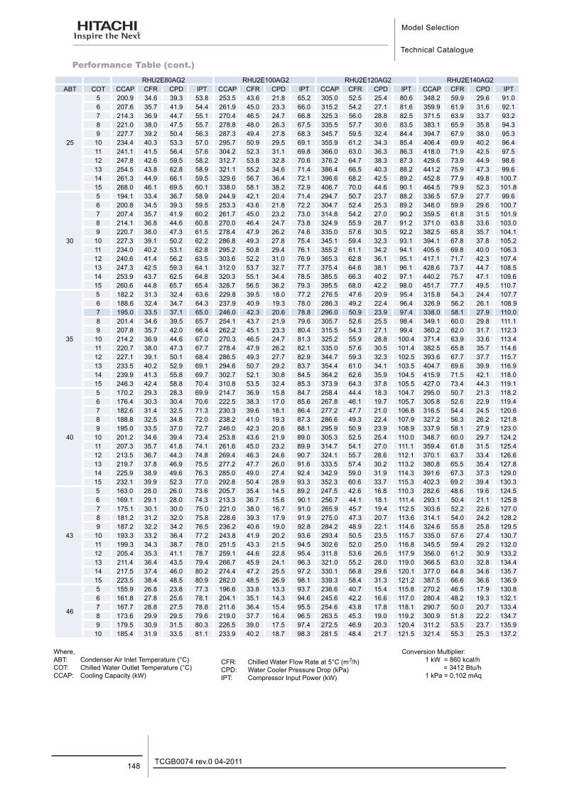
Model Selection
Technical Catalogue
TCGB0074 rev.0 04-2011148
Performance Table (cont.)
Where,ABT: Condenser Air Inlet Temperature (°C)COT: Chilled Water Outlet Temperature (°C)CCAP: Cooling Capacity (kW)
CFR: Chilled Water Flow Rate at 5°C (m3/h)CPD: Water Cooler Pressure Drop (kPa)IPT: Compressor Input Power (kW)
Conversion Multiplier:1 kW = 860 kcal/h = 3412 Btu/h1 kPa = 0.102 mAq
RHU2E80AG2 RHU2E100AG2 RHU2E120AG2 RHU2E140AG2ABT COT CCAP CFR CPD IPT CCAP CFR CPD IPT CCAP CFR CPD IPT CCAP CFR CPD IPT
25
5 200.9 34.6 39.3 53.8 253.5 43.6 21.8 65.2 305.0 52.5 25.4 80.6 348.2 59.9 29.6 91.0 6 207.6 35.7 41.9 54.4 261.9 45.0 23.3 66.0 315.2 54.2 27.1 81.6 359.9 61.9 31.6 92.1 7 214.3 36.9 44.7 55.1 270.4 46.5 24.7 66.8 325.3 56.0 28.8 82.5 371.5 63.9 33.7 93.2 8 221.0 38.0 47.5 55.7 278.8 48.0 26.3 67.5 335.5 57.7 30.6 83.5 383.1 65.9 35.8 94.3 9 227.7 39.2 50.4 56.3 287.3 49.4 27.8 68.3 345.7 59.5 32.4 84.4 394.7 67.9 38.0 95.3
10 234.4 40.3 53.3 57.0 295.7 50.9 29.5 69.1 355.9 61.2 34.3 85.4 406.4 69.9 40.2 96.4 11 241.1 41.5 56.4 57.6 304.2 52.3 31.1 69.8 366.0 63.0 36.3 86.3 418.0 71.9 42.5 97.5 12 247.8 42.6 59.5 58.2 312.7 53.8 32.8 70.6 376.2 64.7 38.3 87.3 429.6 73.9 44.9 98.6 13 254.5 43.8 62.8 58.9 321.1 55.2 34.6 71.4 386.4 66.5 40.3 88.2 441.2 75.9 47.3 99.6 14 261.3 44.9 66.1 59.5 329.6 56.7 36.4 72.1 396.6 68.2 42.5 89.2 452.8 77.9 49.8 100.7 15 268.0 46.1 69.5 60.1 338.0 58.1 38.2 72.9 406.7 70.0 44.6 90.1 464.5 79.9 52.3 101.8
30
5 194.1 33.4 36.7 58.9 244.9 42.1 20.4 71.4 294.7 50.7 23.7 88.2 336.5 57.9 27.7 99.6 6 200.8 34.5 39.3 59.5 253.3 43.6 21.8 72.2 304.7 52.4 25.3 89.2 348.0 59.9 29.6 100.7 7 207.4 35.7 41.9 60.2 261.7 45.0 23.2 73.0 314.8 54.2 27.0 90.2 359.5 61.8 31.5 101.9 8 214.1 36.8 44.6 60.8 270.0 46.4 24.7 73.8 324.9 55.9 28.7 91.2 371.0 63.8 33.6 103.0 9 220.7 38.0 47.3 61.5 278.4 47.9 26.2 74.6 335.0 57.6 30.5 92.2 382.5 65.8 35.7 104.1
10 227.3 39.1 50.2 62.2 286.8 49.3 27.8 75.4 345.1 59.4 32.3 93.1 394.1 67.8 37.8 105.2 11 234.0 40.2 53.1 62.8 295.2 50.8 29.4 76.1 355.2 61.1 34.2 94.1 405.6 69.8 40.0 106.3 12 240.6 41.4 56.2 63.5 303.6 52.2 31.0 76.9 365.3 62.8 36.1 95.1 417.1 71.7 42.3 107.4 13 247.3 42.5 59.3 64.1 312.0 53.7 32.7 77.7 375.4 64.6 38.1 96.1 428.6 73.7 44.7 108.5 14 253.9 43.7 62.5 64.8 320.3 55.1 34.4 78.5 385.5 66.3 40.2 97.1 440.2 75.7 47.1 109.6 15 260.6 44.8 65.7 65.4 328.7 56.5 36.2 79.3 395.5 68.0 42.2 98.0 451.7 77.7 49.5 110.7
35
5 182.2 31.3 32.4 63.6 229.8 39.5 18.0 77.2 276.5 47.6 20.9 95.4 315.8 54.3 24.4 107.7 6 188.6 32.4 34.7 64.3 237.9 40.9 19.3 78.0 286.3 49.2 22.4 96.4 326.9 56.2 26.1 108.9 7 195.0 33.5 37.1 65.0 246.0 42.3 20.6 78.8 296.0 50.9 23.9 97.4 338.0 58.1 27.9 110.0 8 201.4 34.6 39.5 65.7 254.1 43.7 21.9 79.6 305.7 52.6 25.5 98.4 349.1 60.0 29.8 111.1 9 207.8 35.7 42.0 66.4 262.2 45.1 23.3 80.4 315.5 54.3 27.1 99.4 360.2 62.0 31.7 112.3
10 214.2 36.9 44.6 67.0 270.3 46.5 24.7 81.3 325.2 55.9 28.8 100.4 371.4 63.9 33.6 113.4 11 220.7 38.0 47.3 67.7 278.4 47.9 26.2 82.1 335.0 57.6 30.5 101.4 382.5 65.8 35.7 114.6 12 227.1 39.1 50.1 68.4 286.5 49.3 27.7 82.9 344.7 59.3 32.3 102.5 393.6 67.7 37.7 115.7 13 233.5 40.2 52.9 69.1 294.6 50.7 29.2 83.7 354.4 61.0 34.1 103.5 404.7 69.6 39.9 116.9 14 239.9 41.3 55.8 69.7 302.7 52.1 30.8 84.5 364.2 62.6 35.9 104.5 415.9 71.5 42.1 118.0 15 246.3 42.4 58.8 70.4 310.8 53.5 32.4 85.3 373.9 64.3 37.8 105.5 427.0 73.4 44.3 119.1
40
5 170.2 29.3 28.3 69.9 214.7 36.9 15.8 84.7 258.4 44.4 18.3 104.7 295.0 50.7 21.3 118.2 6 176.4 30.3 30.4 70.6 222.5 38.3 17.0 85.6 267.8 46.1 19.7 105.7 305.8 52.6 22.9 119.4 7 182.6 31.4 32.5 71.3 230.3 39.6 18.1 86.4 277.2 47.7 21.0 106.8 316.5 54.4 24.5 120.6 8 188.8 32.5 34.8 72.0 238.2 41.0 19.3 87.3 286.6 49.3 22.4 107.9 327.2 56.3 26.2 121.8 9 195.0 33.5 37.0 72.7 246.0 42.3 20.6 88.1 295.9 50.9 23.9 108.9 337.9 58.1 27.9 123.0
10 201.2 34.6 39.4 73.4 253.8 43.6 21.9 89.0 305.3 52.5 25.4 110.0 348.7 60.0 29.7 124.2 11 207.3 35.7 41.8 74.1 261.6 45.0 23.2 89.9 314.7 54.1 27.0 111.1 359.4 61.8 31.5 125.4 12 213.5 36.7 44.3 74.8 269.4 46.3 24.6 90.7 324.1 55.7 28.6 112.1 370.1 63.7 33.4 126.6 13 219.7 37.8 46.9 75.5 277.2 47.7 26.0 91.6 333.5 57.4 30.2 113.2 380.8 65.5 35.4 127.8 14 225.9 38.9 49.6 76.3 285.0 49.0 27.4 92.4 342.9 59.0 31.9 114.3 391.6 67.3 37.3 129.0 15 232.1 39.9 52.3 77.0 292.8 50.4 28.9 93.3 352.3 60.6 33.7 115.3 402.3 69.2 39.4 130.3
43
5 163.0 28.0 26.0 73.6 205.7 35.4 14.5 89.2 247.5 42.6 16.8 110.3 282.6 48.6 19.6 124.5 6 169.1 29.1 28.0 74.3 213.3 36.7 15.6 90.1 256.7 44.1 18.1 111.4 293.1 50.4 21.1 125.8 7 175.1 30.1 30.0 75.0 221.0 38.0 16.7 91.0 265.9 45.7 19.4 112.5 303.6 52.2 22.6 127.0 8 181.2 31.2 32.0 75.8 228.6 39.3 17.9 91.9 275.0 47.3 20.7 113.6 314.1 54.0 24.2 128.2 9 187.2 32.2 34.2 76.5 236.2 40.6 19.0 92.8 284.2 48.9 22.1 114.6 324.6 55.8 25.8 129.5
10 193.3 33.2 36.4 77.2 243.8 41.9 20.2 93.6 293.4 50.5 23.5 115.7 335.0 57.6 27.4 130.7 11 199.3 34.3 38.7 78.0 251.5 43.3 21.5 94.5 302.6 52.0 25.0 116.8 345.5 59.4 29.2 132.0 12 205.4 35.3 41.1 78.7 259.1 44.6 22.8 95.4 311.8 53.6 26.5 117.9 356.0 61.2 30.9 133.2 13 211.4 36.4 43.5 79.4 266.7 45.9 24.1 96.3 321.0 55.2 28.0 119.0 366.5 63.0 32.8 134.4 14 217.5 37.4 46.0 80.2 274.4 47.2 25.5 97.2 330.1 56.8 29.6 120.1 377.0 64.8 34.6 135.7 15 223.5 38.4 48.5 80.9 282.0 48.5 26.9 98.1 339.3 58.4 31.3 121.2 387.5 66.6 36.6 136.9
46
5 155.9 26.8 23.8 77.3 196.6 33.8 13.3 93.7 236.6 40.7 15.4 115.8 270.2 46.5 17.9 130.8 6 161.8 27.8 25.6 78.1 204.1 35.1 14.3 94.6 245.6 42.2 16.6 117.0 280.4 48.2 19.3 132.1 7 167.7 28.8 27.5 78.8 211.6 36.4 15.4 95.5 254.6 43.8 17.8 118.1 290.7 50.0 20.7 133.4 8 173.6 29.9 29.5 79.6 219.0 37.7 16.4 96.5 263.5 45.3 19.0 119.2 300.9 51.8 22.2 134.7 9 179.5 30.9 31.5 80.3 226.5 39.0 17.5 97.4 272.5 46.9 20.3 120.4 311.2 53.5 23.7 135.9
10 185.4 31.9 33.5 81.1 233.9 40.2 18.7 98.3 281.5 48.4 21.7 121.5 321.4 55.3 25.3 137.2
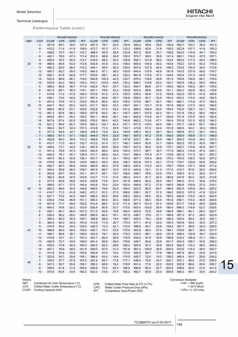
Model Selection
Technical Catalogue
15
149TCGB0074 rev.0 04-2011
Performance Table (cont.)
RHU2E160AG2 RHU2E180AG2 RHU2E210AG2 RHU2E240AG2ABT COT CCAP CFR CPD IPT CCAP CFR CPD IPT CCAP CFR CPD IPT CCAP CFR CPD IPT
25
5 401.8 69.1 39.3 107.6 457.5 78.7 25.4 120.9 522.4 89.8 29.6 136.6 602.7 103.7 39.3 161.4 6 415.2 71.4 41.9 108.9 472.7 81.3 27.1 122.3 539.8 92.8 31.6 138.2 622.8 107.1 41.9 163.3 7 428.6 73.7 44.7 110.1 488.0 83.9 28.8 123.8 557.2 95.8 33.7 139.8 643.0 110.6 44.7 165.2 8 442.1 76.0 47.5 111.4 503.3 86.6 30.6 125.2 574.7 98.8 35.8 141.4 663.1 114.0 47.5 167.1 9 455.5 78.3 50.4 112.7 518.5 89.2 32.4 126.6 592.1 101.8 38.0 143.0 683.2 117.5 50.4 169.0
10 468.9 80.6 53.3 113.9 533.8 91.8 34.3 128.0 609.5 104.8 40.2 144.6 703.3 121.0 53.3 170.9 11 482.3 83.0 56.4 115.2 549.1 94.4 36.3 129.5 627.0 107.8 42.5 146.2 723.4 124.4 56.4 172.8 12 495.7 85.3 59.5 116.5 564.3 97.1 38.3 130.9 644.4 110.8 44.9 147.8 743.5 127.9 59.5 174.7 13 509.1 87.6 62.8 117.7 579.6 99.7 40.3 132.3 661.8 113.8 47.3 149.4 763.6 131.3 62.8 176.6 14 522.5 89.9 66.1 119.0 594.9 102.3 42.5 133.7 679.3 116.8 49.8 151.0 783.8 134.8 66.1 178.5 15 535.9 92.2 69.5 120.3 610.1 104.9 44.6 135.2 696.7 119.8 52.3 152.7 803.9 138.3 69.5 180.4
30
5 388.2 66.8 36.7 117.8 442.0 76.0 23.7 132.3 504.7 86.8 27.7 149.5 582.3 100.2 36.7 176.6 6 401.5 69.1 39.3 119.1 457.1 78.6 25.3 133.8 522.0 89.8 29.6 151.1 602.3 103.6 39.3 178.6 7 414.8 71.3 41.9 120.4 472.3 81.2 27.0 135.3 539.3 92.8 31.5 152.8 622.2 107.0 41.9 180.6 8 428.1 73.6 44.6 121.7 487.4 83.8 28.7 136.8 556.5 95.7 33.6 154.5 642.2 110.5 44.6 182.5 9 441.4 75.9 47.3 123.0 502.5 86.4 30.5 138.2 573.8 98.7 35.7 156.1 662.1 113.9 47.3 184.5
10 454.7 78.2 50.2 124.3 517.7 89.0 32.3 139.7 591.1 101.7 37.8 157.8 682.0 117.3 50.2 186.5 11 468.0 80.5 53.1 125.6 532.8 91.6 34.2 141.2 608.4 104.6 40.0 159.4 702.0 120.7 53.1 188.4 12 481.3 82.8 56.2 126.9 547.9 94.2 36.1 142.7 625.7 107.6 42.3 161.1 721.9 124.2 56.2 190.4 13 494.6 85.1 59.3 128.2 563.1 96.8 38.1 144.1 642.9 110.6 44.7 162.8 741.9 127.6 59.3 192.4 14 507.9 87.4 62.5 129.6 578.2 99.4 40.2 145.6 660.2 113.6 47.1 164.4 761.8 131.0 62.5 194.3 15 521.2 89.6 65.7 130.9 593.3 102.1 42.2 147.1 677.5 116.5 49.5 166.1 781.7 134.5 65.7 196.3
35
5 364.3 62.7 32.4 127.3 414.8 71.3 20.9 143.1 473.6 81.5 24.4 161.6 546.5 94.0 32.4 190.9 6 377.2 64.9 34.7 128.6 429.4 73.9 22.4 144.6 490.3 84.3 26.1 163.3 565.8 97.3 34.7 193.0 7 390.0 67.1 37.1 130.0 444.0 76.4 23.9 146.1 507.0 87.2 27.9 165.0 585.0 100.6 37.1 195.0 8 402.8 69.3 39.5 131.4 458.6 78.9 25.5 147.6 523.7 90.1 29.8 166.7 604.2 103.9 39.5 197.0 9 415.7 71.5 42.0 132.7 473.2 81.4 27.1 149.1 540.4 92.9 31.7 168.4 623.5 107.2 42.0 199.1
10 428.5 73.7 44.6 134.1 487.8 83.9 28.8 150.7 557.0 95.8 33.6 170.1 642.7 110.6 44.6 201.1 11 441.3 75.9 47.3 135.4 502.4 86.4 30.5 152.2 573.7 98.7 35.7 171.9 662.0 113.9 47.3 203.1 12 454.2 78.1 50.1 136.8 517.1 88.9 32.3 153.7 590.4 101.6 37.7 173.6 681.2 117.2 50.1 205.1 13 467.0 80.3 52.9 138.1 531.7 91.4 34.1 155.2 607.1 104.4 39.9 175.3 700.5 120.5 52.9 207.2 14 479.8 82.5 55.8 139.5 546.3 94.0 35.9 156.7 623.8 107.3 42.1 177.0 719.7 123.8 55.8 209.2 15 492.7 84.7 58.8 140.8 560.9 96.5 37.8 158.2 640.5 110.2 44.3 178.7 739.0 127.1 58.8 211.2
40
5 340.4 58.6 28.3 139.7 387.6 66.7 18.3 157.0 442.6 76.1 21.3 177.3 510.7 87.8 28.3 209.6 6 352.8 60.7 30.4 141.1 401.7 69.1 19.7 158.6 458.7 78.9 22.9 179.1 529.2 91.0 30.4 211.7 7 365.2 62.8 32.5 142.6 415.7 71.5 21.0 160.2 474.7 81.7 24.5 180.9 547.8 94.2 32.5 213.8 8 377.6 64.9 34.8 144.0 429.8 73.9 22.4 161.8 490.8 84.4 26.2 182.7 566.3 97.4 34.8 216.0 9 389.9 67.1 37.0 145.4 443.9 76.4 23.9 163.4 506.9 87.2 27.9 184.5 584.9 100.6 37.0 218.1
10 402.3 69.2 39.4 146.8 458.0 78.8 25.4 165.0 523.0 90.0 29.7 186.4 603.5 103.8 39.4 220.2 11 414.7 71.3 41.8 148.2 472.1 81.2 27.0 166.6 539.1 92.7 31.5 188.2 622.0 107.0 41.8 222.4 12 427.1 73.5 44.3 149.7 486.2 83.6 28.6 168.2 555.2 95.5 33.4 190.0 640.6 110.2 44.3 224.5 13 439.4 75.6 46.9 151.1 500.3 86.0 30.2 169.8 571.3 98.3 35.4 191.8 659.1 113.4 46.9 226.6 14 451.8 77.7 49.6 152.5 514.4 88.5 31.9 171.4 587.3 101.0 37.3 193.6 677.7 116.6 49.6 228.8 15 464.2 79.8 52.3 153.9 528.4 90.9 33.7 173.0 603.4 103.8 39.4 195.4 696.3 119.8 52.3 230.9
43
5 326.1 56.1 26.0 147.2 371.3 63.9 16.8 165.4 423.9 72.9 19.6 186.8 489.1 84.1 26.0 220.7 6 338.2 58.2 28.0 148.6 385.0 66.2 18.1 167.0 439.7 75.6 21.1 188.6 507.3 87.3 28.0 222.9 7 350.3 60.3 30.0 150.1 398.8 68.6 19.4 168.7 455.4 78.3 22.6 190.5 525.4 90.4 30.0 225.1 8 362.4 62.3 32.0 151.6 412.6 71.0 20.7 170.3 471.1 81.0 24.2 192.4 543.6 93.5 32.0 227.3 9 374.5 64.4 34.2 153.0 426.3 73.3 22.1 172.0 486.8 83.7 25.8 194.2 561.7 96.6 34.2 229.5
10 386.6 66.5 36.4 154.5 440.1 75.7 23.5 173.6 502.6 86.4 27.4 196.1 579.9 99.7 36.4 231.7 11 398.7 68.6 38.7 156.0 453.9 78.1 25.0 175.3 518.3 89.1 29.2 197.9 598.0 102.9 38.7 233.9 12 410.8 70.7 41.1 157.4 467.7 80.4 26.5 176.9 534.0 91.9 30.9 199.8 616.2 106.0 41.1 236.1 13 422.9 72.7 43.5 158.9 481.4 82.8 28.0 178.6 549.7 94.6 32.8 201.7 634.3 109.1 43.5 238.3 14 435.0 74.8 46.0 160.3 495.2 85.2 29.6 180.2 565.5 97.3 34.6 203.5 652.5 112.2 46.0 240.5 15 447.1 76.9 48.5 161.8 509.0 87.5 31.3 181.8 581.2 100.0 36.6 205.4 670.6 115.3 48.5 242.7
46
5 311.8 53.6 23.8 154.6 354.9 61.0 15.4 173.8 405.3 69.7 17.9 196.2 467.6 80.4 23.8 231.9 6 323.6 55.7 25.6 156.1 368.4 63.4 16.6 175.5 420.7 72.4 19.3 198.2 485.4 83.5 25.6 234.2 7 335.4 57.7 27.5 157.6 381.8 65.7 17.8 177.1 436.0 75.0 20.7 200.1 503.1 86.5 27.5 236.4 8 347.2 59.7 29.5 159.1 395.3 68.0 19.0 178.8 451.4 77.6 22.2 202.0 520.8 89.6 29.5 238.7 9 359.0 61.8 31.5 160.6 408.8 70.3 20.3 180.5 466.8 80.3 23.7 203.9 538.6 92.6 31.5 241.0
10 370.9 63.8 33.5 162.2 422.2 72.6 21.7 182.2 482.1 82.9 25.3 205.8 556.3 95.7 33.5 243.2
Where,ABT: Condenser Air Inlet Temperature (°C)COT: Chilled Water Outlet Temperature (°C)CCAP: Cooling Capacity (kW)
CFR: Chilled Water Flow Rate at 5°C (m3/h)CPD: Water Cooler Pressure Drop (kPa)IPT: Compressor Input Power (kW)
Conversion Multiplier:1 kW = 860 kcal/h = 3412 Btu/h1 kPa = 0.102 mAq
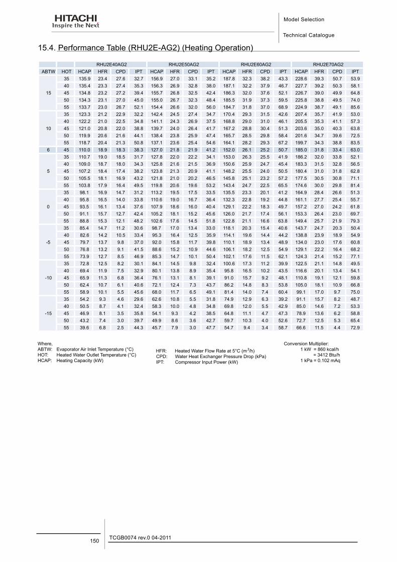
Model Selection
Technical Catalogue
TCGB0074 rev.0 04-2011150
15.4. Performance Table (RHU2E-AG2) (Heating Operation)
RHU2E40AG2 RHU2E50AG2 RHU2E60AG2 RHU2E70AG2ABTW HOT HCAP HFR CPD IPT HCAP HFR CPD IPT HCAP HFR CPD IPT HCAP HFR CPD IPT
15
35 135.9 23.4 27.6 32.7 156.9 27.0 33.1 35.2 187.8 32.3 38.2 43.3 228.6 39.3 50.7 53.9 40 135.4 23.3 27.4 35.3 156.3 26.9 32.8 38.0 187.1 32.2 37.9 46.7 227.7 39.2 50.3 58.1 45 134.8 23.2 27.2 39.4 155.7 26.8 32.5 42.4 186.3 32.0 37.6 52.1 226.7 39.0 49.9 64.8 50 134.3 23.1 27.0 45.0 155.0 26.7 32.3 48.4 185.5 31.9 37.3 59.5 225.8 38.8 49.5 74.0 55 133.7 23.0 26.7 52.1 154.4 26.6 32.0 56.0 184.7 31.8 37.0 68.9 224.9 38.7 49.1 85.6
10
35 123.3 21.2 22.9 32.2 142.4 24.5 27.4 34.7 170.4 29.3 31.5 42.6 207.4 35.7 41.9 53.0 40 122.2 21.0 22.5 34.8 141.1 24.3 26.9 37.5 168.8 29.0 31.0 46.1 205.5 35.3 41.1 57.3 45 121.0 20.8 22.0 38.8 139.7 24.0 26.4 41.7 167.2 28.8 30.4 51.3 203.6 35.0 40.3 63.8 50 119.9 20.6 21.6 44.1 138.4 23.8 25.9 47.4 165.7 28.5 29.8 58.4 201.6 34.7 39.6 72.5 55 118.7 20.4 21.3 50.8 137.1 23.6 25.4 54.6 164.1 28.2 29.3 67.2 199.7 34.3 38.8 83.5
6 45 110.0 18.9 18.3 38.3 127.0 21.8 21.9 41.2 152.0 26.1 25.2 50.7 185.0 31.8 33.4 63.0
5
35 110.7 19.0 18.5 31.7 127.8 22.0 22.2 34.1 153.0 26.3 25.5 41.9 186.2 32.0 33.8 52.1 40 109.0 18.7 18.0 34.3 125.8 21.6 21.5 36.9 150.6 25.9 24.7 45.4 183.3 31.5 32.8 56.5 45 107.2 18.4 17.4 38.2 123.8 21.3 20.9 41.1 148.2 25.5 24.0 50.5 180.4 31.0 31.8 62.8 50 105.5 18.1 16.9 43.2 121.8 21.0 20.2 46.5 145.8 25.1 23.2 57.2 177.5 30.5 30.8 71.1 55 103.8 17.9 16.4 49.5 119.8 20.6 19.6 53.2 143.4 24.7 22.5 65.5 174.6 30.0 29.8 81.4
0
35 98.1 16.9 14.7 31.2 113.2 19.5 17.5 33.5 135.5 23.3 20.1 41.2 164.9 28.4 26.6 51.3 40 95.8 16.5 14.0 33.8 110.6 19.0 16.7 36.4 132.3 22.8 19.2 44.8 161.1 27.7 25.4 55.7 45 93.5 16.1 13.4 37.6 107.9 18.6 16.0 40.4 129.1 22.2 18.3 49.7 157.2 27.0 24.2 61.8 50 91.1 15.7 12.7 42.4 105.2 18.1 15.2 45.6 126.0 21.7 17.4 56.1 153.3 26.4 23.0 69.7 55 88.8 15.3 12.1 48.2 102.6 17.6 14.5 51.8 122.8 21.1 16.6 63.8 149.4 25.7 21.9 79.3
-5
35 85.4 14.7 11.2 30.6 98.7 17.0 13.4 33.0 118.1 20.3 15.4 40.6 143.7 24.7 20.3 50.4 40 82.6 14.2 10.5 33.4 95.3 16.4 12.5 35.9 114.1 19.6 14.4 44.2 138.8 23.9 18.9 54.9 45 79.7 13.7 9.8 37.0 92.0 15.8 11.7 39.8 110.1 18.9 13.4 48.9 134.0 23.0 17.6 60.8 50 76.8 13.2 9.1 41.5 88.6 15.2 10.9 44.6 106.1 18.2 12.5 54.9 129.1 22.2 16.4 68.2 55 73.9 12.7 8.5 46.9 85.3 14.7 10.1 50.4 102.1 17.6 11.5 62.1 124.3 21.4 15.2 77.1
-10
35 72.8 12.5 8.2 30.1 84.1 14.5 9.8 32.4 100.6 17.3 11.2 39.9 122.5 21.1 14.8 49.5 40 69.4 11.9 7.5 32.9 80.1 13.8 8.9 35.4 95.8 16.5 10.2 43.5 116.6 20.1 13.4 54.1 45 65.9 11.3 6.8 36.4 76.1 13.1 8.1 39.1 91.0 15.7 9.2 48.1 110.8 19.1 12.1 59.8 50 62.4 10.7 6.1 40.6 72.1 12.4 7.3 43.7 86.2 14.8 8.3 53.8 105.0 18.1 10.9 66.8 55 58.9 10.1 5.5 45.6 68.0 11.7 6.5 49.1 81.4 14.0 7.4 60.4 99.1 17.0 9.7 75.0
-15
35 54.2 9.3 4.6 29.6 62.6 10.8 5.5 31.8 74.9 12.9 6.3 39.2 91.1 15.7 8.2 48.7 40 50.5 8.7 4.1 32.4 58.3 10.0 4.8 34.8 69.8 12.0 5.5 42.9 85.0 14.6 7.2 53.3 45 46.9 8.1 3.5 35.8 54.1 9.3 4.2 38.5 64.8 11.1 4.7 47.3 78.9 13.6 6.2 58.8 50 43.2 7.4 3.0 39.7 49.9 8.6 3.6 42.7 59.7 10.3 4.0 52.6 72.7 12.5 5.3 65.4 55 39.6 6.8 2.5 44.3 45.7 7.9 3.0 47.7 54.7 9.4 3.4 58.7 66.6 11.5 4.4 72.9
Where,ABTW: Evaporator Air Inlet Temperature (°C)HOT: Heated Water Outlet Temperature (°C)HCAP: Heating Capacity (kW)
HFR: Heated Water Flow Rate at 5°C (m3/h)CPD: Water Heat Exchanger Pressure Drop (kPa)IPT: Compressor Input Power (kW)
Conversion Multiplier:1 kW = 860 kcal/h = 3412 Btu/h1 kPa = 0.102 mAq
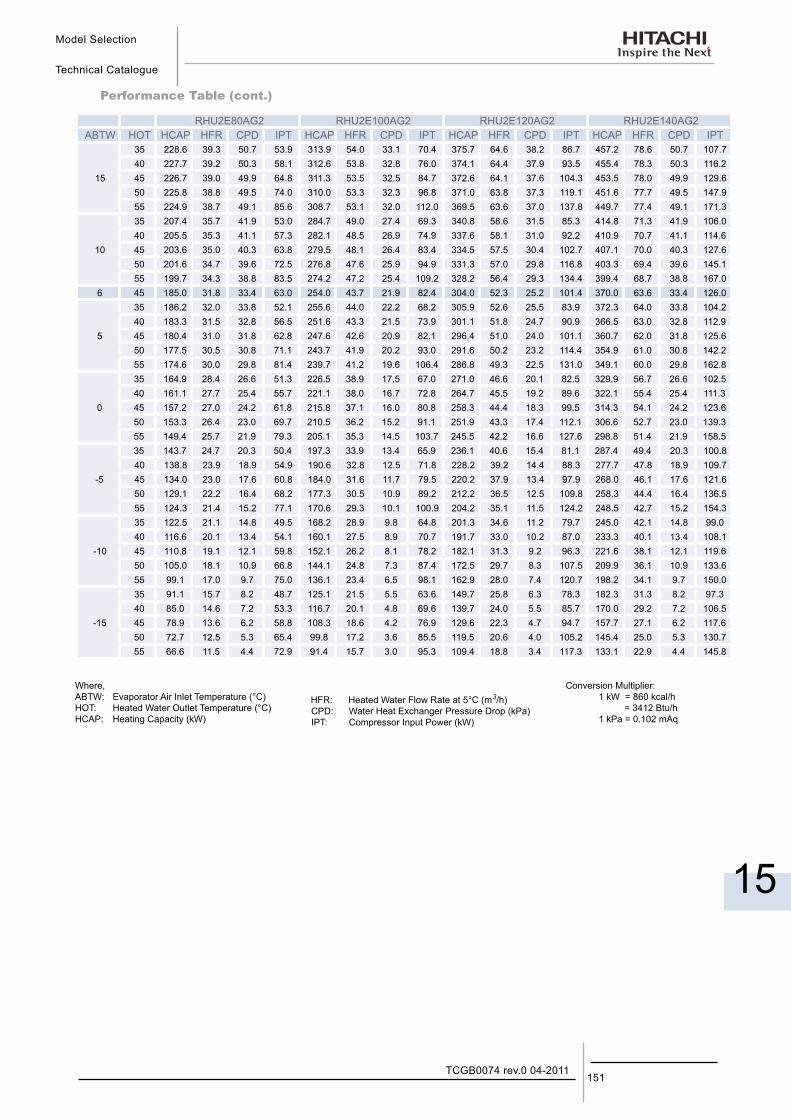
Model Selection
Technical Catalogue
15
151TCGB0074 rev.0 04-2011
Performance Table (cont.)
RHU2E80AG2 RHU2E100AG2 RHU2E120AG2 RHU2E140AG2ABTW HOT HCAP HFR CPD IPT HCAP HFR CPD IPT HCAP HFR CPD IPT HCAP HFR CPD IPT
15
35 228.6 39.3 50.7 53.9 313.9 54.0 33.1 70.4 375.7 64.6 38.2 86.7 457.2 78.6 50.7 107.7 40 227.7 39.2 50.3 58.1 312.6 53.8 32.8 76.0 374.1 64.4 37.9 93.5 455.4 78.3 50.3 116.2 45 226.7 39.0 49.9 64.8 311.3 53.5 32.5 84.7 372.6 64.1 37.6 104.3 453.5 78.0 49.9 129.6 50 225.8 38.8 49.5 74.0 310.0 53.3 32.3 96.8 371.0 63.8 37.3 119.1 451.6 77.7 49.5 147.9 55 224.9 38.7 49.1 85.6 308.7 53.1 32.0 112.0 369.5 63.6 37.0 137.8 449.7 77.4 49.1 171.3
10
35 207.4 35.7 41.9 53.0 284.7 49.0 27.4 69.3 340.8 58.6 31.5 85.3 414.8 71.3 41.9 106.0 40 205.5 35.3 41.1 57.3 282.1 48.5 26.9 74.9 337.6 58.1 31.0 92.2 410.9 70.7 41.1 114.6 45 203.6 35.0 40.3 63.8 279.5 48.1 26.4 83.4 334.5 57.5 30.4 102.7 407.1 70.0 40.3 127.6 50 201.6 34.7 39.6 72.5 276.8 47.6 25.9 94.9 331.3 57.0 29.8 116.8 403.3 69.4 39.6 145.1 55 199.7 34.3 38.8 83.5 274.2 47.2 25.4 109.2 328.2 56.4 29.3 134.4 399.4 68.7 38.8 167.0
6 45 185.0 31.8 33.4 63.0 254.0 43.7 21.9 82.4 304.0 52.3 25.2 101.4 370.0 63.6 33.4 126.0
5
35 186.2 32.0 33.8 52.1 255.6 44.0 22.2 68.2 305.9 52.6 25.5 83.9 372.3 64.0 33.8 104.2 40 183.3 31.5 32.8 56.5 251.6 43.3 21.5 73.9 301.1 51.8 24.7 90.9 366.5 63.0 32.8 112.9 45 180.4 31.0 31.8 62.8 247.6 42.6 20.9 82.1 296.4 51.0 24.0 101.1 360.7 62.0 31.8 125.6 50 177.5 30.5 30.8 71.1 243.7 41.9 20.2 93.0 291.6 50.2 23.2 114.4 354.9 61.0 30.8 142.2 55 174.6 30.0 29.8 81.4 239.7 41.2 19.6 106.4 286.8 49.3 22.5 131.0 349.1 60.0 29.8 162.8
0
35 164.9 28.4 26.6 51.3 226.5 38.9 17.5 67.0 271.0 46.6 20.1 82.5 329.9 56.7 26.6 102.5 40 161.1 27.7 25.4 55.7 221.1 38.0 16.7 72.8 264.7 45.5 19.2 89.6 322.1 55.4 25.4 111.3 45 157.2 27.0 24.2 61.8 215.8 37.1 16.0 80.8 258.3 44.4 18.3 99.5 314.3 54.1 24.2 123.6 50 153.3 26.4 23.0 69.7 210.5 36.2 15.2 91.1 251.9 43.3 17.4 112.1 306.6 52.7 23.0 139.3 55 149.4 25.7 21.9 79.3 205.1 35.3 14.5 103.7 245.5 42.2 16.6 127.6 298.8 51.4 21.9 158.5
-5
35 143.7 24.7 20.3 50.4 197.3 33.9 13.4 65.9 236.1 40.6 15.4 81.1 287.4 49.4 20.3 100.8 40 138.8 23.9 18.9 54.9 190.6 32.8 12.5 71.8 228.2 39.2 14.4 88.3 277.7 47.8 18.9 109.7 45 134.0 23.0 17.6 60.8 184.0 31.6 11.7 79.5 220.2 37.9 13.4 97.9 268.0 46.1 17.6 121.6 50 129.1 22.2 16.4 68.2 177.3 30.5 10.9 89.2 212.2 36.5 12.5 109.8 258.3 44.4 16.4 136.5 55 124.3 21.4 15.2 77.1 170.6 29.3 10.1 100.9 204.2 35.1 11.5 124.2 248.5 42.7 15.2 154.3
-10
35 122.5 21.1 14.8 49.5 168.2 28.9 9.8 64.8 201.3 34.6 11.2 79.7 245.0 42.1 14.8 99.0 40 116.6 20.1 13.4 54.1 160.1 27.5 8.9 70.7 191.7 33.0 10.2 87.0 233.3 40.1 13.4 108.1 45 110.8 19.1 12.1 59.8 152.1 26.2 8.1 78.2 182.1 31.3 9.2 96.3 221.6 38.1 12.1 119.6 50 105.0 18.1 10.9 66.8 144.1 24.8 7.3 87.4 172.5 29.7 8.3 107.5 209.9 36.1 10.9 133.6 55 99.1 17.0 9.7 75.0 136.1 23.4 6.5 98.1 162.9 28.0 7.4 120.7 198.2 34.1 9.7 150.0
-15
35 91.1 15.7 8.2 48.7 125.1 21.5 5.5 63.6 149.7 25.8 6.3 78.3 182.3 31.3 8.2 97.3 40 85.0 14.6 7.2 53.3 116.7 20.1 4.8 69.6 139.7 24.0 5.5 85.7 170.0 29.2 7.2 106.5 45 78.9 13.6 6.2 58.8 108.3 18.6 4.2 76.9 129.6 22.3 4.7 94.7 157.7 27.1 6.2 117.6 50 72.7 12.5 5.3 65.4 99.8 17.2 3.6 85.5 119.5 20.6 4.0 105.2 145.4 25.0 5.3 130.7 55 66.6 11.5 4.4 72.9 91.4 15.7 3.0 95.3 109.4 18.8 3.4 117.3 133.1 22.9 4.4 145.8
Where,ABTW: Evaporator Air Inlet Temperature (°C)HOT: Heated Water Outlet Temperature (°C)HCAP: Heating Capacity (kW)
HFR: Heated Water Flow Rate at 5°C (m3/h)CPD: Water Heat Exchanger Pressure Drop (kPa)IPT: Compressor Input Power (kW)
Conversion Multiplier:1 kW = 860 kcal/h = 3412 Btu/h1 kPa = 0.102 mAq
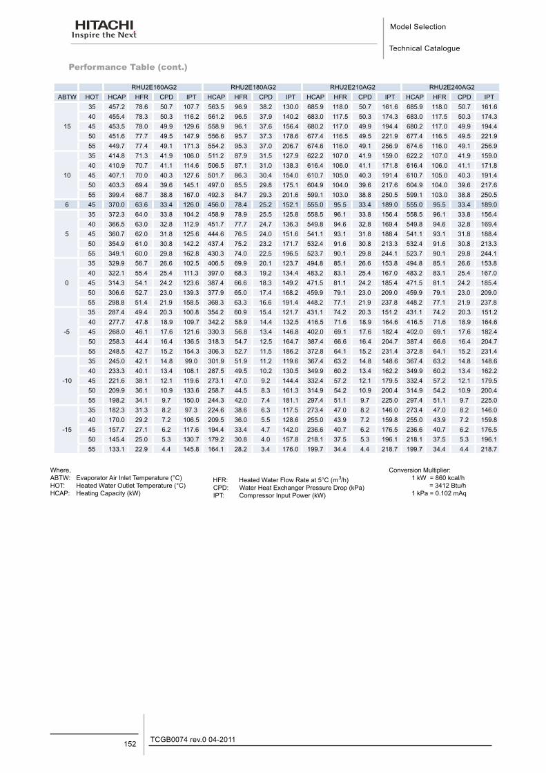
Model Selection
Technical Catalogue
TCGB0074 rev.0 04-2011152
Performance Table (cont.)
RHU2E160AG2 RHU2E180AG2 RHU2E210AG2 RHU2E240AG2ABTW HOT HCAP HFR CPD IPT HCAP HFR CPD IPT HCAP HFR CPD IPT HCAP HFR CPD IPT
15
35 457.2 78.6 50.7 107.7 563.5 96.9 38.2 130.0 685.9 118.0 50.7 161.6 685.9 118.0 50.7 161.6 40 455.4 78.3 50.3 116.2 561.2 96.5 37.9 140.2 683.0 117.5 50.3 174.3 683.0 117.5 50.3 174.3 45 453.5 78.0 49.9 129.6 558.9 96.1 37.6 156.4 680.2 117.0 49.9 194.4 680.2 117.0 49.9 194.4 50 451.6 77.7 49.5 147.9 556.6 95.7 37.3 178.6 677.4 116.5 49.5 221.9 677.4 116.5 49.5 221.9 55 449.7 77.4 49.1 171.3 554.2 95.3 37.0 206.7 674.6 116.0 49.1 256.9 674.6 116.0 49.1 256.9
10
35 414.8 71.3 41.9 106.0 511.2 87.9 31.5 127.9 622.2 107.0 41.9 159.0 622.2 107.0 41.9 159.0 40 410.9 70.7 41.1 114.6 506.5 87.1 31.0 138.3 616.4 106.0 41.1 171.8 616.4 106.0 41.1 171.8 45 407.1 70.0 40.3 127.6 501.7 86.3 30.4 154.0 610.7 105.0 40.3 191.4 610.7 105.0 40.3 191.4 50 403.3 69.4 39.6 145.1 497.0 85.5 29.8 175.1 604.9 104.0 39.6 217.6 604.9 104.0 39.6 217.6 55 399.4 68.7 38.8 167.0 492.3 84.7 29.3 201.6 599.1 103.0 38.8 250.5 599.1 103.0 38.8 250.5
6 45 370.0 63.6 33.4 126.0 456.0 78.4 25.2 152.1 555.0 95.5 33.4 189.0 555.0 95.5 33.4 189.0
5
35 372.3 64.0 33.8 104.2 458.9 78.9 25.5 125.8 558.5 96.1 33.8 156.4 558.5 96.1 33.8 156.4 40 366.5 63.0 32.8 112.9 451.7 77.7 24.7 136.3 549.8 94.6 32.8 169.4 549.8 94.6 32.8 169.4 45 360.7 62.0 31.8 125.6 444.6 76.5 24.0 151.6 541.1 93.1 31.8 188.4 541.1 93.1 31.8 188.4 50 354.9 61.0 30.8 142.2 437.4 75.2 23.2 171.7 532.4 91.6 30.8 213.3 532.4 91.6 30.8 213.3 55 349.1 60.0 29.8 162.8 430.3 74.0 22.5 196.5 523.7 90.1 29.8 244.1 523.7 90.1 29.8 244.1
0
35 329.9 56.7 26.6 102.5 406.5 69.9 20.1 123.7 494.8 85.1 26.6 153.8 494.8 85.1 26.6 153.8 40 322.1 55.4 25.4 111.3 397.0 68.3 19.2 134.4 483.2 83.1 25.4 167.0 483.2 83.1 25.4 167.0 45 314.3 54.1 24.2 123.6 387.4 66.6 18.3 149.2 471.5 81.1 24.2 185.4 471.5 81.1 24.2 185.4 50 306.6 52.7 23.0 139.3 377.9 65.0 17.4 168.2 459.9 79.1 23.0 209.0 459.9 79.1 23.0 209.0 55 298.8 51.4 21.9 158.5 368.3 63.3 16.6 191.4 448.2 77.1 21.9 237.8 448.2 77.1 21.9 237.8
-5
35 287.4 49.4 20.3 100.8 354.2 60.9 15.4 121.7 431.1 74.2 20.3 151.2 431.1 74.2 20.3 151.2 40 277.7 47.8 18.9 109.7 342.2 58.9 14.4 132.5 416.5 71.6 18.9 164.6 416.5 71.6 18.9 164.6 45 268.0 46.1 17.6 121.6 330.3 56.8 13.4 146.8 402.0 69.1 17.6 182.4 402.0 69.1 17.6 182.4 50 258.3 44.4 16.4 136.5 318.3 54.7 12.5 164.7 387.4 66.6 16.4 204.7 387.4 66.6 16.4 204.7 55 248.5 42.7 15.2 154.3 306.3 52.7 11.5 186.2 372.8 64.1 15.2 231.4 372.8 64.1 15.2 231.4
-10
35 245.0 42.1 14.8 99.0 301.9 51.9 11.2 119.6 367.4 63.2 14.8 148.6 367.4 63.2 14.8 148.6 40 233.3 40.1 13.4 108.1 287.5 49.5 10.2 130.5 349.9 60.2 13.4 162.2 349.9 60.2 13.4 162.2 45 221.6 38.1 12.1 119.6 273.1 47.0 9.2 144.4 332.4 57.2 12.1 179.5 332.4 57.2 12.1 179.5 50 209.9 36.1 10.9 133.6 258.7 44.5 8.3 161.3 314.9 54.2 10.9 200.4 314.9 54.2 10.9 200.4 55 198.2 34.1 9.7 150.0 244.3 42.0 7.4 181.1 297.4 51.1 9.7 225.0 297.4 51.1 9.7 225.0
-15
35 182.3 31.3 8.2 97.3 224.6 38.6 6.3 117.5 273.4 47.0 8.2 146.0 273.4 47.0 8.2 146.0 40 170.0 29.2 7.2 106.5 209.5 36.0 5.5 128.6 255.0 43.9 7.2 159.8 255.0 43.9 7.2 159.8 45 157.7 27.1 6.2 117.6 194.4 33.4 4.7 142.0 236.6 40.7 6.2 176.5 236.6 40.7 6.2 176.5 50 145.4 25.0 5.3 130.7 179.2 30.8 4.0 157.8 218.1 37.5 5.3 196.1 218.1 37.5 5.3 196.1 55 133.1 22.9 4.4 145.8 164.1 28.2 3.4 176.0 199.7 34.4 4.4 218.7 199.7 34.4 4.4 218.7
Where,ABTW: Evaporator Air Inlet Temperature (°C)HOT: Heated Water Outlet Temperature (°C)HCAP: Heating Capacity (kW)
HFR: Heated Water Flow Rate at 5°C (m3/h)CPD: Water Heat Exchanger Pressure Drop (kPa)IPT: Compressor Input Power (kW)
Conversion Multiplier:1 kW = 860 kcal/h = 3412 Btu/h1 kPa = 0.102 mAq
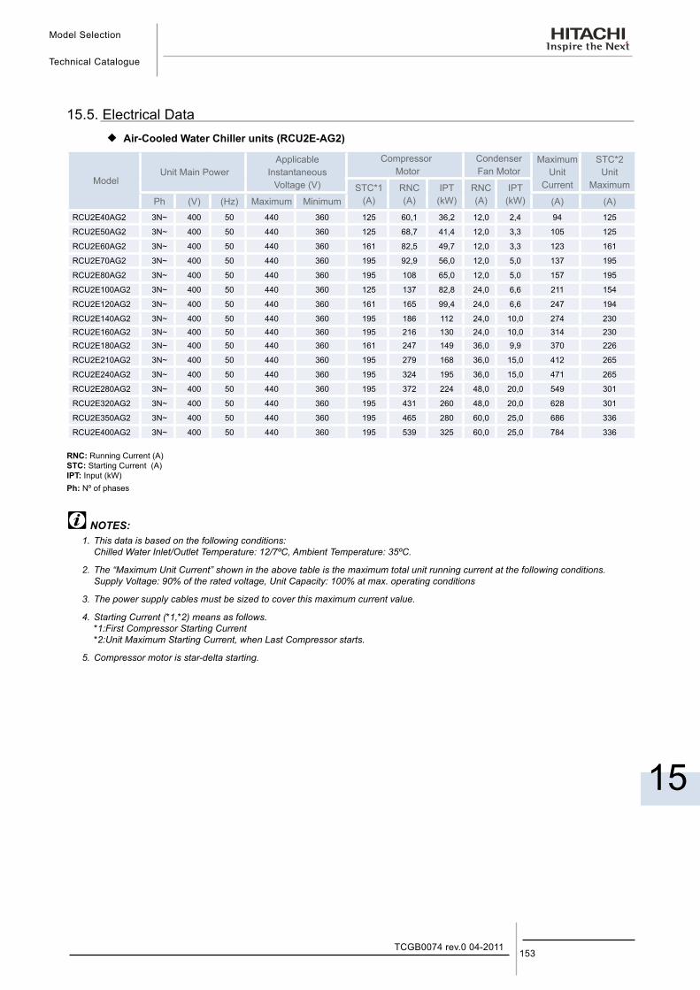
Model Selection
Technical Catalogue
15
153TCGB0074 rev.0 04-2011
15.5. Electrical Data ¡ Air-Cooled Water Chiller units (RCU2E-AG2)
ModelUnit Main Power
ApplicableInstantaneous
Voltage (V)
Compressor Motor
CondenserFan Motor
MaximumUnit
Current
STC*2Unit
MaximumSTC*1(A)
RNC(A)
IPT(kW)
RNC(A)
IPT(kW)Ph (V) (Hz) Maximum Minimum (A) (A)
RCU2E40AG2 3N~ 400 50 440 360 125 60,1 36,2 12,0 2,4 94 125
RCU2E50AG2 3N~ 400 50 440 360 125 68,7 41,4 12,0 3,3 105 125
RCU2E60AG2 3N~ 400 50 440 360 161 82,5 49,7 12,0 3,3 123 161
RCU2E70AG2 3N~ 400 50 440 360 195 92,9 56,0 12,0 5,0 137 195
RCU2E80AG2 3N~ 400 50 440 360 195 108 65,0 12,0 5,0 157 195
RCU2E100AG2 3N~ 400 50 440 360 125 137 82,8 24,0 6,6 211 154
RCU2E120AG2 3N~ 400 50 440 360 161 165 99,4 24,0 6,6 247 194
RCU2E140AG2 3N~ 400 50 440 360 195 186 112 24,0 10,0 274 230 RCU2E160AG2 3N~ 400 50 440 360 195 216 130 24,0 10,0 314 230 RCU2E180AG2 3N~ 400 50 440 360 161 247 149 36,0 9,9 370 226
RCU2E210AG2 3N~ 400 50 440 360 195 279 168 36,0 15,0 412 265
RCU2E240AG2 3N~ 400 50 440 360 195 324 195 36,0 15,0 471 265
RCU2E280AG2 3N~ 400 50 440 360 195 372 224 48,0 20,0 549 301
RCU2E320AG2 3N~ 400 50 440 360 195 431 260 48,0 20,0 628 301
RCU2E350AG2 3N~ 400 50 440 360 195 465 280 60,0 25,0 686 336
RCU2E400AG2 3N~ 400 50 440 360 195 539 325 60,0 25,0 784 336
RNC: Running Current (A)STC: Starting Current (A) IPT: Input (kW)Ph: Nº of phases
NOTES:1. This data is based on the following conditions:
Chilled Water Inlet/Outlet Temperature: 12/7ºC, Ambient Temperature: 35ºC.
2. The “Maximum Unit Current” shown in the above table is the maximum total unit running current at the following conditions. Supply Voltage: 90% of the rated voltage, Unit Capacity: 100% at max. operating conditions
3. The power supply cables must be sized to cover this maximum current value.
4. Starting Current (*1,*2) means as follows. *1:First Compressor Starting Current *2:Unit Maximum Starting Current, when Last Compressor starts.
5. Compressor motor is star-delta starting.
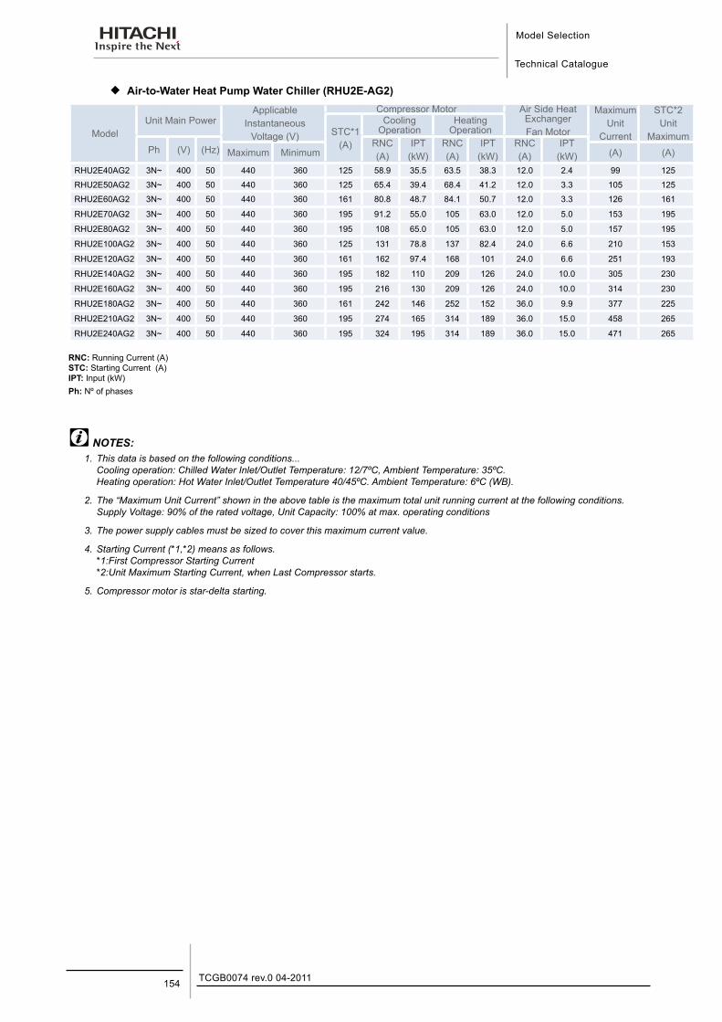
Model Selection
Technical Catalogue
TCGB0074 rev.0 04-2011154
¡ Air-to-Water Heat Pump Water Chiller (RHU2E-AG2)
ModelUnit Main Power
Applicable Instantaneous
Voltage (V)
Compressor Motor Air Side Heat ExchangerFan Motor
MaximumUnit
Current
STC*2Unit
MaximumSTC*1(A)
Cooling Operation
Heating Operation
Ph (V) (Hz)RNC(A)
IPT(kW)
RNC(A)
IPT(kW)
RNC(A)
IPT(kW)Maximum Minimum (A) (A)
RHU2E40AG2 3N~ 400 50 440 360 125 58.9 35.5 63.5 38.3 12.0 2.4 99 125
RHU2E50AG2 3N~ 400 50 440 360 125 65.4 39.4 68.4 41.2 12.0 3.3 105 125
RHU2E60AG2 3N~ 400 50 440 360 161 80.8 48.7 84.1 50.7 12.0 3.3 126 161
RHU2E70AG2 3N~ 400 50 440 360 195 91.2 55.0 105 63.0 12.0 5.0 153 195
RHU2E80AG2 3N~ 400 50 440 360 195 108 65.0 105 63.0 12.0 5.0 157 195
RHU2E100AG2 3N~ 400 50 440 360 125 131 78.8 137 82.4 24.0 6.6 210 153
RHU2E120AG2 3N~ 400 50 440 360 161 162 97.4 168 101 24.0 6.6 251 193
RHU2E140AG2 3N~ 400 50 440 360 195 182 110 209 126 24.0 10.0 305 230
RHU2E160AG2 3N~ 400 50 440 360 195 216 130 209 126 24.0 10.0 314 230
RHU2E180AG2 3N~ 400 50 440 360 161 242 146 252 152 36.0 9.9 377 225
RHU2E210AG2 3N~ 400 50 440 360 195 274 165 314 189 36.0 15.0 458 265
RHU2E240AG2 3N~ 400 50 440 360 195 324 195 314 189 36.0 15.0 471 265
RNC: Running Current (A)STC: Starting Current (A) IPT: Input (kW)Ph: Nº of phases
NOTES:1. This data is based on the following conditions...
Cooling operation: Chilled Water Inlet/Outlet Temperature: 12/7ºC, Ambient Temperature: 35ºC. Heating operation: Hot Water Inlet/Outlet Temperature 40/45ºC. Ambient Temperature: 6ºC (WB).
2. The “Maximum Unit Current” shown in the above table is the maximum total unit running current at the following conditions. Supply Voltage: 90% of the rated voltage, Unit Capacity: 100% at max. operating conditions
3. The power supply cables must be sized to cover this maximum current value.
4. Starting Current (*1,*2) means as follows. *1:First Compressor Starting Current *2:Unit Maximum Starting Current, when Last Compressor starts.
5. Compressor motor is star-delta starting.
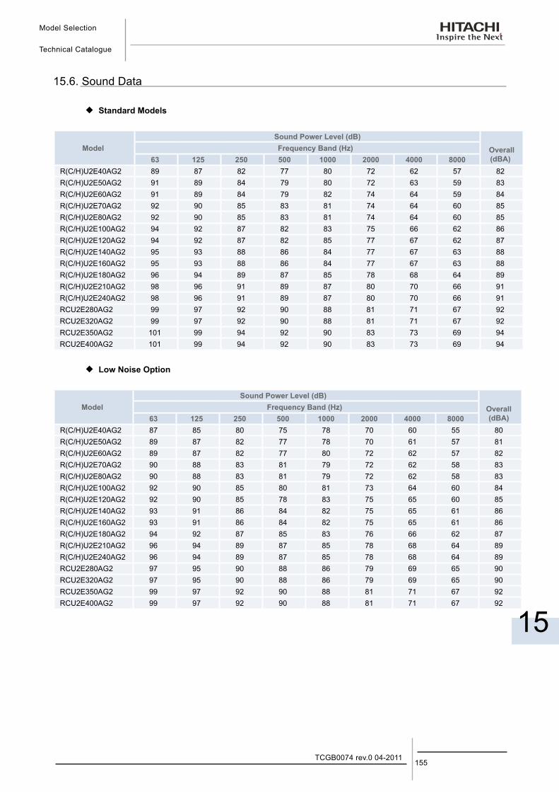
Model Selection
Technical Catalogue
15
155TCGB0074 rev.0 04-2011
15.6. Sound Data
¡ Standard Models
ModelSound Power Level (dB)
Overall (dBA)
Frequency Band (Hz)63 125 250 500 1000 2000 4000 8000
R(C/H)U2E40AG2 89 87 82 77 80 72 62 57 82R(C/H)U2E50AG2 91 89 84 79 80 72 63 59 83R(C/H)U2E60AG2 91 89 84 79 82 74 64 59 84R(C/H)U2E70AG2 92 90 85 83 81 74 64 60 85R(C/H)U2E80AG2 92 90 85 83 81 74 64 60 85R(C/H)U2E100AG2 94 92 87 82 83 75 66 62 86R(C/H)U2E120AG2 94 92 87 82 85 77 67 62 87R(C/H)U2E140AG2 95 93 88 86 84 77 67 63 88R(C/H)U2E160AG2 95 93 88 86 84 77 67 63 88R(C/H)U2E180AG2 96 94 89 87 85 78 68 64 89R(C/H)U2E210AG2 98 96 91 89 87 80 70 66 91R(C/H)U2E240AG2 98 96 91 89 87 80 70 66 91RCU2E280AG2 99 97 92 90 88 81 71 67 92RCU2E320AG2 99 97 92 90 88 81 71 67 92RCU2E350AG2 101 99 94 92 90 83 73 69 94RCU2E400AG2 101 99 94 92 90 83 73 69 94
¡ Low Noise Option
ModelSound Power Level (dB)
Overall(dBA)
Frequency Band (Hz)63 125 250 500 1000 2000 4000 8000
R(C/H)U2E40AG2 87 85 80 75 78 70 60 55 80R(C/H)U2E50AG2 89 87 82 77 78 70 61 57 81R(C/H)U2E60AG2 89 87 82 77 80 72 62 57 82R(C/H)U2E70AG2 90 88 83 81 79 72 62 58 83R(C/H)U2E80AG2 90 88 83 81 79 72 62 58 83R(C/H)U2E100AG2 92 90 85 80 81 73 64 60 84R(C/H)U2E120AG2 92 90 85 78 83 75 65 60 85R(C/H)U2E140AG2 93 91 86 84 82 75 65 61 86R(C/H)U2E160AG2 93 91 86 84 82 75 65 61 86R(C/H)U2E180AG2 94 92 87 85 83 76 66 62 87R(C/H)U2E210AG2 96 94 89 87 85 78 68 64 89R(C/H)U2E240AG2 96 94 89 87 85 78 68 64 89RCU2E280AG2 97 95 90 88 86 79 69 65 90RCU2E320AG2 97 95 90 88 86 79 69 65 90RCU2E350AG2 99 97 92 90 88 81 71 67 92RCU2E400AG2 99 97 92 90 88 81 71 67 92
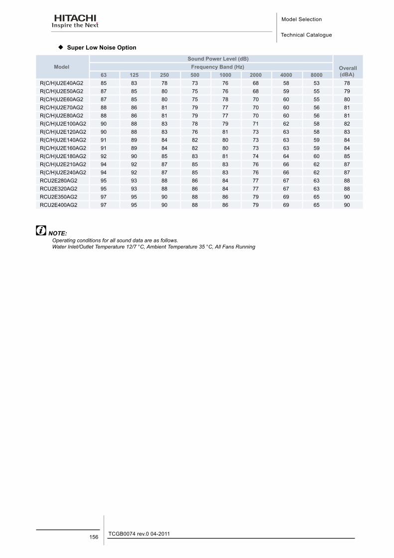
Model Selection
Technical Catalogue
TCGB0074 rev.0 04-2011156
¡ Super Low Noise Option
ModelSound Power Level (dB)
Overall (dBA)
Frequency Band (Hz)63 125 250 500 1000 2000 4000 8000
R(C/H)U2E40AG2 85 83 78 73 76 68 58 53 78R(C/H)U2E50AG2 87 85 80 75 76 68 59 55 79R(C/H)U2E60AG2 87 85 80 75 78 70 60 55 80R(C/H)U2E70AG2 88 86 81 79 77 70 60 56 81R(C/H)U2E80AG2 88 86 81 79 77 70 60 56 81R(C/H)U2E100AG2 90 88 83 78 79 71 62 58 82R(C/H)U2E120AG2 90 88 83 76 81 73 63 58 83R(C/H)U2E140AG2 91 89 84 82 80 73 63 59 84R(C/H)U2E160AG2 91 89 84 82 80 73 63 59 84R(C/H)U2E180AG2 92 90 85 83 81 74 64 60 85R(C/H)U2E210AG2 94 92 87 85 83 76 66 62 87R(C/H)U2E240AG2 94 92 87 85 83 76 66 62 87RCU2E280AG2 95 93 88 86 84 77 67 63 88RCU2E320AG2 95 93 88 86 84 77 67 63 88RCU2E350AG2 97 95 90 88 86 79 69 65 90RCU2E400AG2 97 95 90 88 86 79 69 65 90
NOTE:Operating conditions for all sound data are as follows. Water Inlet/Outlet Temperature 12/7 °C, Ambient Temperature 35 °C, All Fans Running
Application Data
Technical Catalogue
16
16. A p p l i c a t i o n D a t a
157TCGB0074 rev.0 04-2011
Contents
16. Application Data.......................................................................................................15716.1. Working Range .................................................................................................................................... 158
16.2. Part Load Performance ....................................................................................................................... 159Model: RCU2E40AG2 ~ RCU2E400AG2 & RHU2E40AG2 ~ RHU2E240AG2 ...................................................... 159
16.3. Ethylene Glycol Application ................................................................................................................. 160
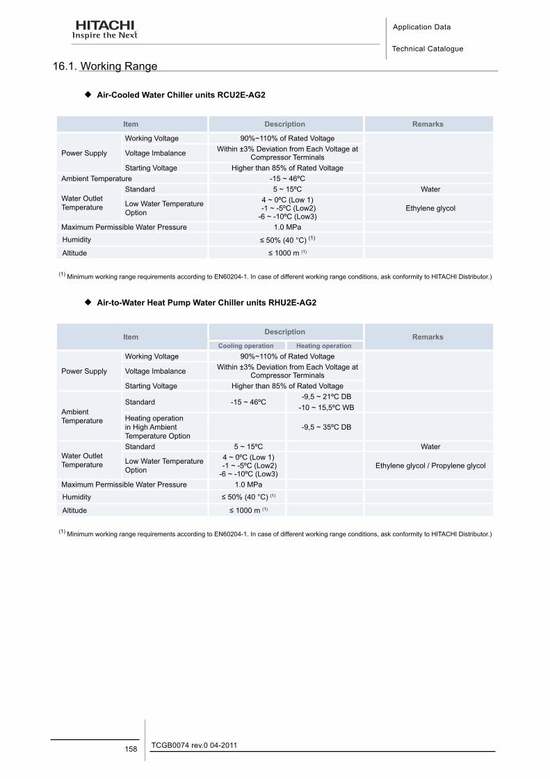
Application Data
Technical Catalogue
TCGB0074 rev.0 04-2011158
16.1. Working Range
¡ Air-Cooled Water Chiller units RCU2E-AG2
Item Description Remarks
Power Supply
Working Voltage 90%~110% of Rated Voltage
Voltage Imbalance Within ±3% Deviation from Each Voltage at Compressor Terminals
Starting Voltage Higher than 85% of Rated VoltageAmbient Temperature -15 ~ 46ºC
Water Outlet Temperature
Standard 5 ~ 15ºC Water
Low Water Temperature Option
4 ~ 0ºC (Low 1) -1 ~ -5ºC (Low2) -6 ~ -10ºC (Low3)
Ethylene glycol
Maximum Permissible Water Pressure 1.0 MPa
Humidity ≤ 50% (40 °C) (1)
Altitude ≤ 1000 m (1)
(1) Minimum working range requirements according to EN60204-1. In case of different working range conditions, ask conformity to HITACHI Distributor.)
¡ Air-to-Water Heat Pump Water Chiller units RHU2E-AG2
ItemDescription
RemarksCooling operation Heating operation
Power Supply
Working Voltage 90%~110% of Rated Voltage
Voltage Imbalance Within ±3% Deviation from Each Voltage at Compressor Terminals
Starting Voltage Higher than 85% of Rated Voltage
Ambient Temperature
Standard -15 ~ 46ºC-9,5 ~ 21ºC DB
-10 ~ 15,5ºC WBHeating operation in High Ambient Temperature Option
-9,5 ~ 35ºC DB
Water Outlet Temperature
Standard 5 ~ 15ºC Water
Low Water Temperature Option
4 ~ 0ºC (Low 1) -1 ~ -5ºC (Low2) -6 ~ -10ºC (Low3)
Ethylene glycol / Propylene glycol
Maximum Permissible Water Pressure 1.0 MPa
Humidity ≤ 50% (40 °C) (1)
Altitude ≤ 1000 m (1)
(1) Minimum working range requirements according to EN60204-1. In case of different working range conditions, ask conformity to HITACHI Distributor.)
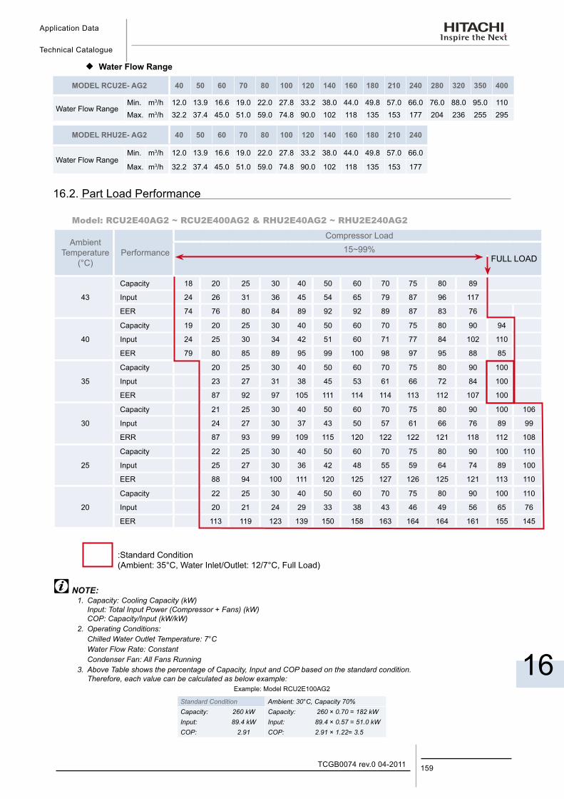
Application Data
Technical Catalogue
16
159TCGB0074 rev.0 04-2011
¡ Water Flow Range
MODEL RCU2E- AG2 40 50 60 70 80 100 120 140 160 180 210 240 280 320 350 400
Water Flow RangeMin. m3/h 12.0 13.9 16.6 19.0 22.0 27.8 33.2 38.0 44.0 49.8 57.0 66.0 76.0 88.0 95.0 110Max. m3/h 32.2 37.4 45.0 51.0 59.0 74.8 90.0 102 118 135 153 177 204 236 255 295
MODEL RHU2E- AG2 40 50 60 70 80 100 120 140 160 180 210 240
Water Flow RangeMin. m3/h 12.0 13.9 16.6 19.0 22.0 27.8 33.2 38.0 44.0 49.8 57.0 66.0
Max. m3/h 32.2 37.4 45.0 51.0 59.0 74.8 90.0 102 118 135 153 177
16.2. Part Load Performance
Model: RCU2E40AG2 ~ RCU2E400AG2 & RHU2E40AG2 ~ RHU2E240AG2
AmbientTemperature
(°C)Performance
Compressor Load15~99%
FULL LOAD
43
Capacity 18 20 25 30 40 50 60 70 75 80 89
Input 24 26 31 36 45 54 65 79 87 96 117
EER 74 76 80 84 89 92 92 89 87 83 76
40
Capacity 19 20 25 30 40 50 60 70 75 80 90 94
Input 24 25 30 34 42 51 60 71 77 84 102 110
EER 79 80 85 89 95 99 100 98 97 95 88 85
35
Capacity 20 25 30 40 50 60 70 75 80 90 100
Input 23 27 31 38 45 53 61 66 72 84 100
EER 87 92 97 105 111 114 114 113 112 107 100
30
Capacity 21 25 30 40 50 60 70 75 80 90 100 106
Input 24 27 30 37 43 50 57 61 66 76 89 99
ERR 87 93 99 109 115 120 122 122 121 118 112 108
25
Capacity 22 25 30 40 50 60 70 75 80 90 100 110
Input 25 27 30 36 42 48 55 59 64 74 89 100
EER 88 94 100 111 120 125 127 126 125 121 113 110
20
Capacity 22 25 30 40 50 60 70 75 80 90 100 110
Input 20 21 24 29 33 38 43 46 49 56 65 76
EER 113 119 123 139 150 158 163 164 164 161 155 145
:Standard Condition (Ambient: 35°C, Water Inlet/Outlet: 12/7°C, Full Load)
NOTE:1. Capacity: Cooling Capacity (kW) Input: Total Input Power (Compressor + Fans) (kW) COP: Capacity/Input (kW/kW)2. Operating Conditions: Chilled Water Outlet Temperature: 7°C Water Flow Rate: Constant Condenser Fan: All Fans Running3. Above Table shows the percentage of Capacity, Input and COP based on the standard condition. Therefore, each value can be calculated as below example:
Example: Model RCU2E100AG2
Standard Condition Ambient: 30°C, Capacity 70%Capacity: 260 kW Capacity: 260 × 0.70 = 182 kWInput: 89.4 kW Input: 89.4 × 0.57 = 51.0 kWCOP: 2.91 COP: 2.91 × 1.22= 3.5
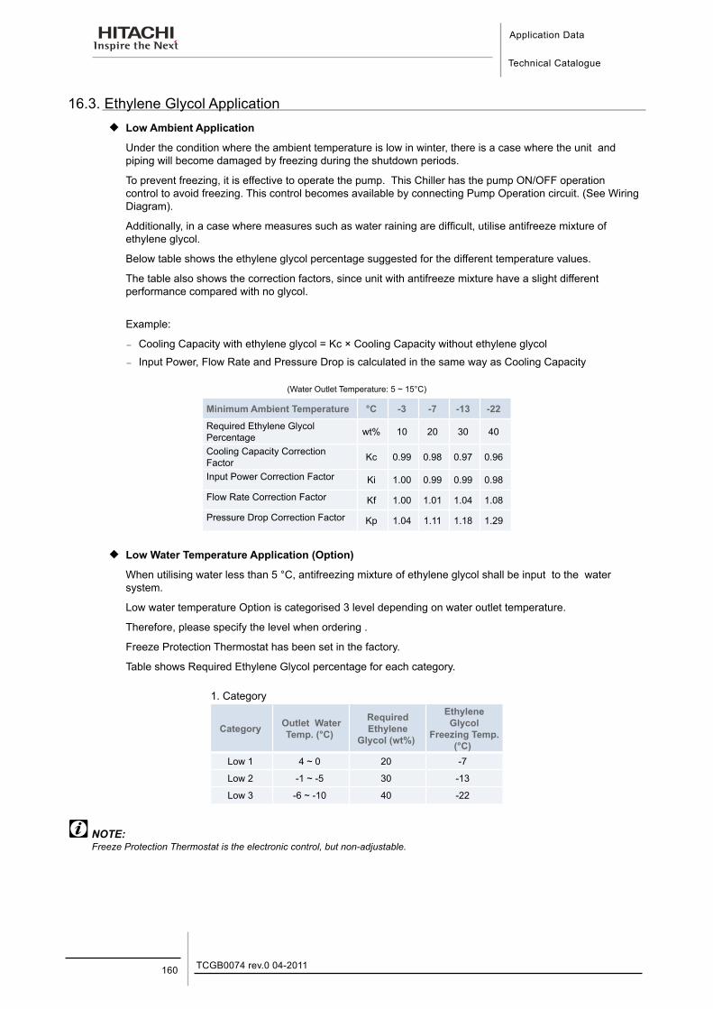
Application Data
Technical Catalogue
TCGB0074 rev.0 04-2011160
16.3. Ethylene Glycol Application ¡ Low Ambient Application
Under the condition where the ambient temperature is low in winter, there is a case where the unit and piping will become damaged by freezing during the shutdown periods.
To prevent freezing, it is effective to operate the pump. This Chiller has the pump ON/OFF operation control to avoid freezing. This control becomes available by connecting Pump Operation circuit. (See Wiring Diagram).
Additionally, in a case where measures such as water raining are difficult, utilise antifreeze mixture of ethylene glycol.
Below table shows the ethylene glycol percentage suggested for the different temperature values.
The table also shows the correction factors, since unit with antifreeze mixture have a slight different performance compared with no glycol.
Example:
− Cooling Capacity with ethylene glycol = Kc × Cooling Capacity without ethylene glycol
− Input Power, Flow Rate and Pressure Drop is calculated in the same way as Cooling Capacity
(Water Outlet Temperature: 5 ~ 15°C)
Minimum Ambient Temperature °C -3 -7 -13 -22
Required Ethylene Glycol Percentage wt% 10 20 30 40
Cooling Capacity Correction Factor Kc 0.99 0.98 0.97 0.96
Input Power Correction Factor Ki 1.00 0.99 0.99 0.98
Flow Rate Correction Factor Kf 1.00 1.01 1.04 1.08
Pressure Drop Correction Factor Kp 1.04 1.11 1.18 1.29
¡ Low Water Temperature Application (Option)
When utilising water less than 5 °C, antifreezing mixture of ethylene glycol shall be input to the water system.
Low water temperature Option is categorised 3 level depending on water outlet temperature.
Therefore, please specify the level when ordering .
Freeze Protection Thermostat has been set in the factory.
Table shows Required Ethylene Glycol percentage for each category.
1. Category
Category Outlet Water Temp. (°C)
Required Ethylene
Glycol (wt%)
Ethylene Glycol
Freezing Temp. (°C)
Low 1 4 ~ 0 20 -7
Low 2 -1 ~ -5 30 -13
Low 3 -6 ~ -10 40 -22
NOTE:Freeze Protection Thermostat is the electronic control, but non-adjustable.
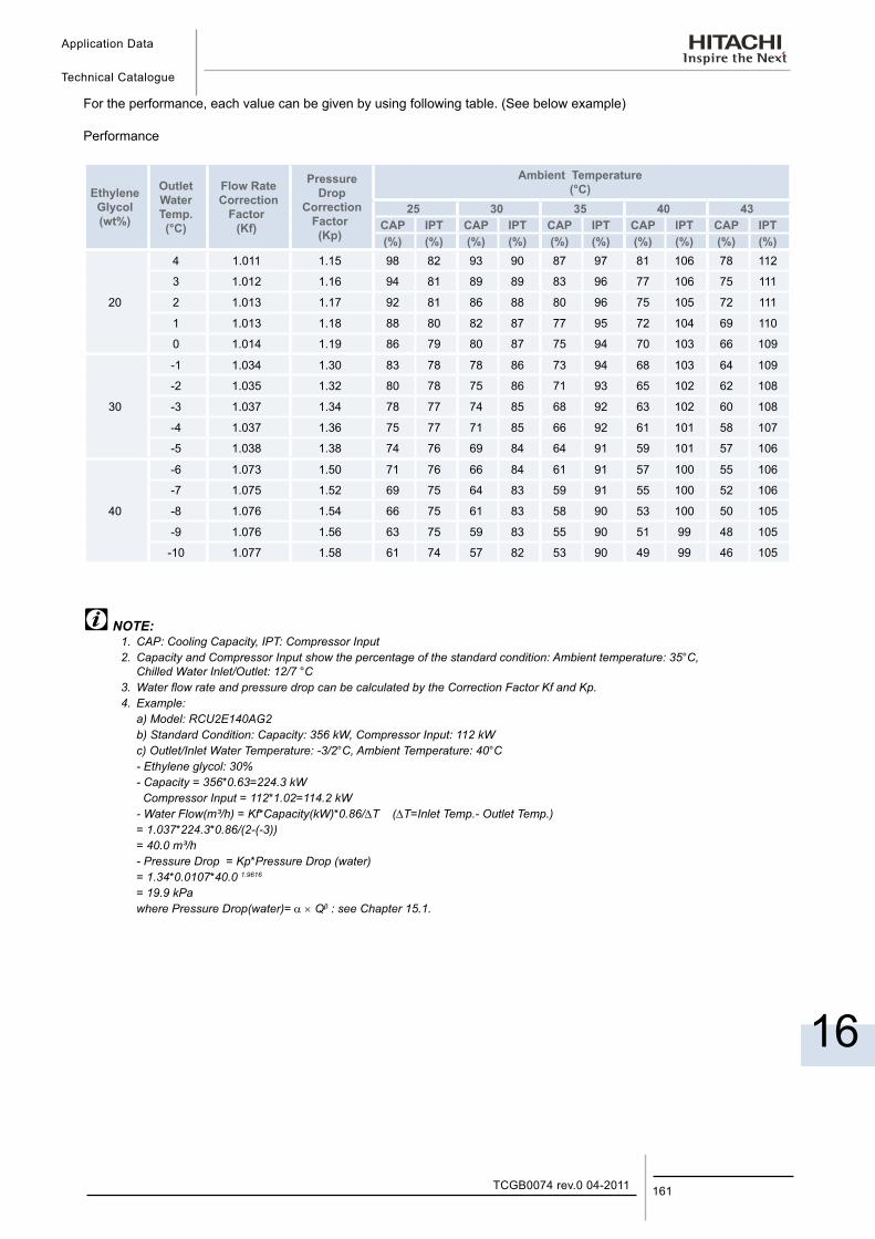
Application Data
Technical Catalogue
16
161TCGB0074 rev.0 04-2011
For the performance, each value can be given by using following table. (See below example)
Performance
EthyleneGlycol(wt%)
OutletWaterTemp.(°C)
Flow Rate Correction
Factor(Kf)
Pressure Drop
Correction Factor(Kp)
Ambient Temperature(°C)
25 30 35 40 43CAP IPT CAP IPT CAP IPT CAP IPT CAP IPT(%) (%) (%) (%) (%) (%) (%) (%) (%) (%)
20
4 1.011 1.15 98 82 93 90 87 97 81 106 78 112
3 1.012 1.16 94 81 89 89 83 96 77 106 75 111
2 1.013 1.17 92 81 86 88 80 96 75 105 72 111
1 1.013 1.18 88 80 82 87 77 95 72 104 69 110
0 1.014 1.19 86 79 80 87 75 94 70 103 66 109
30
-1 1.034 1.30 83 78 78 86 73 94 68 103 64 109
-2 1.035 1.32 80 78 75 86 71 93 65 102 62 108
-3 1.037 1.34 78 77 74 85 68 92 63 102 60 108
-4 1.037 1.36 75 77 71 85 66 92 61 101 58 107
-5 1.038 1.38 74 76 69 84 64 91 59 101 57 106
40
-6 1.073 1.50 71 76 66 84 61 91 57 100 55 106
-7 1.075 1.52 69 75 64 83 59 91 55 100 52 106
-8 1.076 1.54 66 75 61 83 58 90 53 100 50 105
-9 1.076 1.56 63 75 59 83 55 90 51 99 48 105
-10 1.077 1.58 61 74 57 82 53 90 49 99 46 105
NOTE:1. CAP: Cooling Capacity, IPT: Compressor Input2. Capacity and Compressor Input show the percentage of the standard condition: Ambient temperature: 35°C, Chilled Water Inlet/Outlet: 12/7 °C3. Water flow rate and pressure drop can be calculated by the Correction Factor Kf and Kp.4. Example: a) Model: RCU2E140AG2 b) Standard Condition: Capacity: 356 kW, Compressor Input: 112 kW c) Outlet/Inlet Water Temperature: -3/2°C, Ambient Temperature: 40°C - Ethylene glycol: 30% - Capacity = 356*0.63=224.3 kW Compressor Input = 112*1.02=114.2 kW - Water Flow(m³/h) = Kf*Capacity(kW)*0.86/∆T (∆T=Inlet Temp.- Outlet Temp.) = 1.037*224.3*0.86/(2-(-3)) = 40.0 m³/h - Pressure Drop = Kp*Pressure Drop (water) = 1.34*0.0107*40.0 1.9616
= 19.9 kPa where Pressure Drop(water)= α × Qβ : see Chapter 15.1.

Components Data
Technical Catalogue
17
17. C o m p o n e n t s D a t a
163TCGB0074 rev.0 04-2011
Contents
17. Components Data....................................................................................................16317.1. Compressor ......................................................................................................................................... 164
17.2. Air Heat Exchanger and fan................................................................................................................. 164
17.3. Water Heat Exchanger ........................................................................................................................ 165
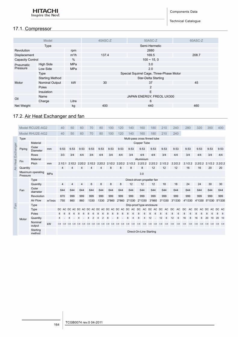
Components Data
Technical Catalogue
TCGB0074 rev.0 04-2011164
17.1. Compressor
Model 40ASC-Z 50ASC-Z 60ASC-ZType Semi-Hermetic
Revolution rpm 2880Displacement m3/h 137.4 169.5 208.7Capacity Control % 100 ~ 15, 0Pneumatic Pressure
High Side MPa 3.0Low Side MPa 2.0
Motor
Type Special Squirrel Cage, Three-Phase MotorStarting Method Star-Delta StartingNominal Output kW 30 37 45Poles 2Insulation E
OilName JAPAN ENERGY, FREOL UX300Charge Litre 6
Net Weight kg 400 440 460
17.2. Air Heat Exchanger and fan
Model RCU2E-AG2 40 50 60 70 80 100 120 140 160 180 210 240 280 320 350 400
Model RHU2E-AG2 40 50 60 70 80 100 120 140 160 180 210 240
Air
Hea
t Exc
hang
er
Type Multi-pass cross finned tube
Piping
Material Copper TubeOuter Diameter mm 9.53 9.53 9.53 9.53 9.53 9.53 9.53 9.53 9.53 9.53 9.53 9.53 9.53 9.53 9.53 9.53
Rows 3/3 3/4 4/4 3/4 4/4 3/4 4/4 3/4 4/4 4/4 3/4 4/4 3/4 4/4 3/4 4/4
FinMaterial AluminiumPitch mm 2.1/2.1 2.1/2.2 2.2/2.2 2.1/2.2 2.2/2.2 2.1/2.2 2.2/2.2 2.1/2.2 2.2/2.2 2.2/2.2 2.1/2.2 2.2/2.2 2.1/2.2 2.2/2.2 2.1/2.2 2.2/2.2
Quantity 4 4 4 4 4 8 8 8 8 12 12 12 16 16 20 20Maximum operating Pressure MPa 3.0
Fan
Fan
Type Direct-driven propeller fanQuantity 4 4 4 6 6 8 8 12 12 12 18 18 24 24 30 30Outer diameter 644 644 644 644 644 644 644 644 644 644 644 644 644 644 644 644
Revolution 870 999 999 999 999 999 999 999 999 999 999 999 999 999 999 999Air Flow m3/min 750 860 860 1330 1330 2*860 2*860 2*1330 2*1330 3*860 3*1330 3*1330 4*1330 4*1330 5*1330 5*1330
Motor
Type Drip-proof type enclosureType DC AC DC AC DC AC DC AC DC AC DC AC DC AC DC AC DC AC DC AC DC AC DC AC DC AC DC AC DC AC DC AC
Poles 8 6 8 6 8 6 8 6 8 6 8 6 8 6 8 6 8 6 8 6 8 6 8 6 8 6 8 6 8 6 8 6
Quantity 4 - 4 - 4 - 4 2 4 2 8 - 8 - 8 4 8 4 12 - 12 6 12 6 16 8 16 8 20 10 20 10
Nominal output kW 0.38 0.28 0.38 0.28 0.38 0.28 0.38 0.28 0.38 0.28 0.38 0.28 0.38 0.28 0.38 0.28 0.38 0.28 0.38 0.28 0.38 0.28 0.38 0.28 0.38 0.28 0.38 0.28 0.38 0.28 0.38 0.28
Starting method Direct-On-Line Starting
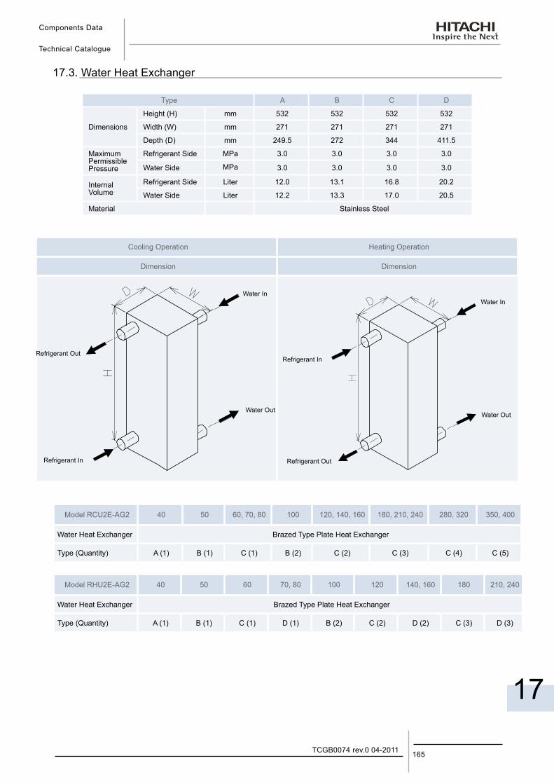
Components Data
Technical Catalogue
17
165TCGB0074 rev.0 04-2011
17.3. Water Heat Exchanger
Type A B C D
Dimensions
Height (H) mm 532 532 532 532
Width (W) mm 271 271 271 271
Depth (D) mm 249.5 272 344 411.5
Maximum Permissible Pressure
Refrigerant Side MPa 3.0 3.0 3.0 3.0
Water Side MPa 3.0 3.0 3.0 3.0
Internal Volume
Refrigerant Side Liter 12.0 13.1 16.8 20.2
Water Side Liter 12.2 13.3 17.0 20.5
Material Stainless Steel
Cooling Operation Heating Operation
Dimension Dimension
Water In
Refrigerant Out
Refrigerant In
Water Out
Water In
Refrigerant In
Refrigerant Out
Water Out
Model RCU2E-AG2 40 50 60, 70, 80 100 120, 140, 160 180, 210, 240 280, 320 350, 400
Water Heat Exchanger Brazed Type Plate Heat Exchanger
Type (Quantity) A (1) B (1) C (1) B (2) C (2) C (3) C (4) C (5)
Model RHU2E-AG2 40 50 60 70, 80 100 120 140, 160 180 210, 240
Water Heat Exchanger Brazed Type Plate Heat Exchanger
Type (Quantity) A (1) B (1) C (1) D (1) B (2) C (2) D (2) C (3) D (3)


Printed in SpainTCGB0074 rev.0 - 04/2011
HITACHI participates in the Eurovent Certification Programme; thecertified data of certified models are listed in the Eurovent CertificationOnline Directory (www.eurovent-certification.com).
Hitachi Air Conditioning Products Europe, S.A. is certified with:ISO 9001 of AENOR, Spain for its Quality Management accordancewith the standardISO 14001 of AENOR Spain for its Environmental Managementsystems accordance with the standard.
Hitachi certifies that our products have met EU consumer safety,health and environmental requirements.
Hitachi Air Conditioning Products Europe, S.A.Ronda Shimizu, 1 - Políg. Ind. Can Torrella08233 Vacarisses (Barcelona) España
TCG
B00
74 re
v.0
- 04/
2011
RCU2E(40-400)AG2RHU2E(40-240)AG2
Technical Catalogue
SAMURAI SERIESAIR COOLED AND AIR TO WATER HEAT PUMPWATER CHILLERS-SCREW TYPE-
SA
MU
RA
I SE
RIE
S A
IR C
OO
LED
AN
D A
IR T
O W
AT
ER
HE
AT
PU
MP
WA
TE
R C
HIL
LER
S -
SC
RE
W T
YP
E-