Embed Size (px)
Citation preview
Air-condensed water chillers andheat pumps YLCA / YLHA
Technical Information
Ref.: N-27697_EN 1110
Index
1 Technical Information...............................................................................................................1
1.1 General Information.................................................................................................................21.1.1 Nomenclature...........................................................................................................................21.1.2 General description of the unit.................................................................................................21.1.3 Models available and capacities...............................................................................................31.1.4 Features and advantages.........................................................................................................31.1.5 Technical specifications...........................................................................................................41.2 Safety instructions....................................................................................................................81.3 Icons used in this document.....................................................................................................81.4 Instructions for storage, transport, loading and unloading of the unit......................................91.4.1 Inspection.................................................................................................................................91.4.2 Disposal of packaging..............................................................................................................91.4.3 Disposal of the unit.................................................................................................................101.4.4 Handling.................................................................................................................................101.5 Selection guide (YLCA/YLHA)...............................................................................................101.5.1 Selection guide with glycol (cooling only units)......................................................................131.6 Technical data........................................................................................................................151.6.1 Limits of use...........................................................................................................................151.6.2 Correction Factors..................................................................................................................151.6.3 Physical data..........................................................................................................................231.6.4 Electrical specifications..........................................................................................................261.7 Measurements, clearances and accesses.............................................................................271.7.1 Clearances.............................................................................................................................271.7.2 Dimensions and hydraulic connections (models YLCA/YLHA 40).........................................291.7.3 Dimensions and hydraulic connections (models YLCA/YLHA 50 and 60).............................301.7.4 Dimensions and hydraulic connections (models YLCA/YLHA 80).........................................311.7.5 Dimensions and hydraulic connections (models YLCA/YLHA 100, 120 and 150).................321.8 Capacities YLHA....................................................................................................................331.8.1 Cooling capacities YLHA 40 ÷ 150.........................................................................................331.8.2 Cooling capacities YLHA 40 ÷ 150 (35% ethylene glycol).....................................................341.8.3 Heating capacities YLHA 40 ÷ 150.........................................................................................351.9 Capacites YLCA.....................................................................................................................361.9.1 Cooling capacities YLCA 40 ÷ 150.........................................................................................361.9.2 Cooling capacities YLCA 40 ÷ 150 (35% ethylene glycol).....................................................371.10 Cooling operation and hydraulic diagrams.............................................................................381.10.1 YLCA models: cooling only....................................................................................................381.10.2 YLHA models: heat pump......................................................................................................421.11 Instructions for installation and connection of the unit...........................................................461.11.1 Characteristics of the location................................................................................................461.11.2 Specifications for the foundation or anchoring of the unit......................................................461.11.3 Hydraulic connections............................................................................................................461.11.4 Rotational direction of Scroll compressors.............................................................................47
Index
i
1.11.5 Preparation and connecting to the various utilities.................................................................471.12 Unit sound power spectrum data........................................................................................... 511.13 Operating instructions............................................................................................................ 521.13.1 Operating instructions µC2 (YLCA/YLHA 40).........................................................................521.13.2 Operating instructions µC2 (YLCA 50, 60 and 80).................................................................681.13.3 Operating instructions µC2 (YLHA 50, 60 and 80).................................................................841.13.4 Operating instructions µC3 (YLCA / YLHA 100, 120 and 150).............................................1021.14 Wiring diagrams ..................................................................................................................1211.14.1 Unit wiring diagrams.............................................................................................................121
Index
ii

1
Technical Information

1.1 General Information1.1.1 Nomenclature Air-water chiller with axial fans / Air-water heat pump with axial fans Nominal cooling capacity in kW Voltage M: Single-phase voltage (230.1.50) T: Three-phase (400.3.50) -: Without hydro kit (pack) P: With hydro kit (pack) M - YLCA / YLHA 60 T P
1.1.2 General description of the unitThe YLCA/YLHA units are high-performance air-water chillers and heat pumps using R-410A ecologicalrefrigerant.
These units are designed for air conditioning or industrial applications that require cold or hot water.
They are silent and compact units, equipped with vertical air discharge axial fans, that can be installeddirectly outdoors.
They are available in two versions: with and without a hydro kit, which includes a buffer tank and a highhead pressure pump.
The control system of these units is a specially programmed electronic controller to be used on air-waterchillers and heat pumps equipped with tandem compressors. Easy to use and safe, these units precisioncontrol the water return temperature of the installation, carry out defrost cycles, modulate fan speedsand control compressor, pump and electric heater start-up. By reading the control sensors and safetyelements, the controller protects the entire equipment against malfunctions. The system allows con‐necting the unit to a standard RS485 monitoring network.
For further information, please see Operating Instructions.
The YLCA/YLHA units are made of proven quality components and manufactured in compliance withstandards in force (ISO 9001 certification).
1 Technical Information1.1 General Information
2
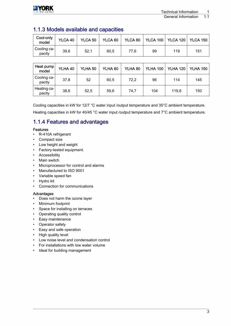
1.1.3 Models available and capacitiesCool-only
model YLCA 40 YLCA 50 YLCA 60 YLCA 80 YLCA 100 YLCA 120 YLCA 150
Cooling ca‐pacity 39,6 52,1 60,5 77,6 99 119 151
Heat pumpmodel YLHA 40 YLHA 50 YLHA 60 YLHA 80 YLHA 100 YLHA 120 YLHA 150
Cooling ca‐pacity 37,8 52 60,5 72,2 96 114 145
Heating ca‐pacity 38,6 52,5 59,6 74,7 104 119,6 150
Cooling capacities in kW for 12/7 °C water input /output temperature and 35°C ambient temperature.
Heating capacities in kW for 40/45 °C water input /output temperature and 7°C ambient temperature.
1.1.4 Features and advantagesFeatures• R-410A refrigerant• Compact size• Low height and weight• Factory-tested equipment.• Accessibility• Main switch• Microprocessor for control and alarms• Manufactured to ISO 9001• Variable speed fan• Hydro kit• Connection for communications
Advantages• Does not harm the ozone layer• Minimum footprint• Space for installing on terraces• Operating quality control• Easy maintenance• Operator safety• Easy and safe operation• High quality level• Low noise level and condensation control• For installations with low water volume• Ideal for building management
Technical Information 1General Information 1.1
3
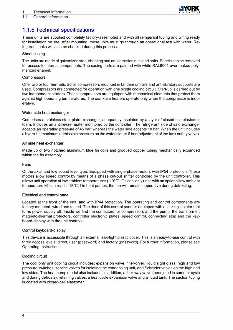
1.1.5 Technical specificationsThese units are supplied completely factory-assembled and with all refrigerant tubing and wiring readyfor installation on site. After mounting, these units must go through an operational test with water. Re‐frigerant leaks will also be checked during this process.
Sheet casing
The units are made of galvanized steel sheeting and anticorrosion nuts and bolts. Panels can be removedfor access to internal components. The casing parts are painted with white RAL9001 oven-baked poly‐merized enamel.
Compressors
One, two or four hermetic Scroll compressors mounted in tandem on rails and antivibratory supports areused. Compressors are connected for operation with one single cooling circuit. Start-up is carried out bytwo independent starters. These compressors are equipped with mechanical elements that protect themagainst high operating temperatures. The crankase heaters operate only when the compressor is inop‐erative.
Water side heat exchanger
Comprises a stainless steel plate exchanger, adequately insulated by a layer of closed-cell elastomerfoam. Includes an antifreeze heater monitored by the controller. The refrigerant side of said exchangeraccepts an operating pressure of 45 bar, whereas the water side accepts 10 bar. When the unit includesa hydro kit, maximum admissible pressure on the water side is 6 bar (adjustment of the tank safety valve).
Air side heat exchanger
Made up of two notched aluminium blue fin coils and grooved copper tubing mechanically expandedwithin the fin assembly.
Fans
Of the axial and low sound level type. Equipped with single-phase motors with IP54 protection. Thesemotors allow speed control by means of a phase cut-out shifter controlled by the unit controller. Thisallows unit operation at low ambient temperatures (-10°C). On cool only units with an optional low ambienttemperature kit can reach ‑18°C. On heat pumps, the fan will remain inoperative during defrosting.
Electrical and control panel
Located at the front of the unit, and with IP44 protection. The operating and control components arefactory mounted, wired and tested. The door of this control panel is equipped with a locking isolator thatturns power supply off. Inside we find the contactors for compressors and the pump, the transformer,magneto-thermal protectors, controller electronic plates, speed control, connecting strip and the key‐board-display with the unit controls.
Control keyboard-display
This device is accessible through an external leak-tight plastic cover. This is an easy-to-use control withthree access levels: direct, user (password) and factory (password). For further information, please seeOperating Instructions.
Cooling circuit
The cool only unit cooling circuit includes: expansion valve, filter-dryer, liquid sight glass, high and lowpressure switches, service valves for isolating the condensing unit, and Schrader valves on the high andlow sides. The heat pump model also includes, in addition, a four-way valve (energized in summer cycleand during defrosts), retaining valves, a heat cycle expansion valve and a liquid tank. The suction tubingis coated with closed-cell elastomer.
1 Technical Information1.1 General Information
4
Hydro kit (pack)
These units include a pack assembled with the components of a hydro kit. This assembly is located withinthe unit frame and does not increase the footprint of same. It includes the following components: Linedbuffer tank and with an antifreeze heater, centrifugal pump, expansion vessel charged with nitrogen at1.5 bar, safety valve set to 6 bar, water circuit, pressure gauge, two air bleed valves, filling valve anddrain valve. Also includes a mesh filter for the water circuit. This filter is supplied loose for installation atthe most convenient point.
Flow switch
Assures sufficient water flow when the unit is in operation.
Technical Information 1General Information 1.1
5
Options and accessoriesUnits without hydro kit
This includes the elements described in the previously mentioned specifications, less the hydro kit (pack).The water circuit includes an air bleed valve. Connections are ready for on-site installation.
Two pumps
Accessory available with models 50 to 150 with hydro kit. The second pump becomes operative whenthe magnetothermal protector of the first pump is activated (models 50, 60 and 80), or through the con‐troller program (models 100, 120 and 150).
Water filter
Supplied as a standard element on units including the hydro kit. Stainless steel mesh with 1 mm. diameterperforations. Optional on units not including the hydro kit. The warranty of the unit will not be valid if awater filter has not been installed.
Remote control
Wall-mounted remote control unit with keyboard for cool /heat and ON /OFF functions. Includes powersupply, alarm and cool /heat LEDs. Maximum cable length: 50 m.
Remote terminal
For total access and control of the system by means of the display and buttons. It allows for selection ofcool, heat and off functions. Operating parameters can also be modified and the system can also besupervised. Can be installed at a maximum distance of 1040 m.
BMS connections
By means of a serial board, it is possible to connect the system to a standard RS485 monitoring network.
Low noise level units (LN)
Include anti-noise covers mounted on the compressors and sound isolating plates, covering the com‐pressor chamber.
Soft starter
For the soft motor start. Specially designed for Scroll compressors. (Maximum outdoor temperature:50℃).
Protecting grids
To protect the coils from possible impacts. Made of steel rods and painted with oven baked polymerizedwhite enamel (RAL9001).
1 Technical Information1.1 General Information
6
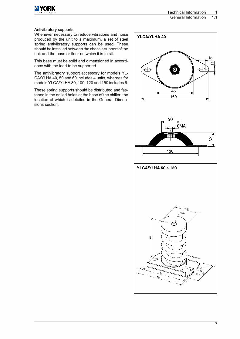
Antivibratory supportsWhenever necessary to reduce vibrations and noiseproduced by the unit to a maximum, a set of steelspring antivibratory supports can be used. Theseshould be installed between the chassis support of theunit and the base or floor on which it is to sit.
This base must be solid and dimensioned in accord‐ance with the load to be supported.
The antivibratory support accessory for models YL‐CA/YLHA 40, 50 and 60 includes 4 units, whereas formodels YLCA/YLHA 80, 100, 120 and 150 includes 6.
These spring supports should be distributed and fas‐tened in the drilled holes at the base of the chiller, thelocation of which is detailed in the General Dimen‐sions section.
Technical Information 1General Information 1.1
7
1.2 Safety instructionsThis document contains the necessary information for the safe and efficient transportation, assemblyand installation of the air conditioning unit. This guarantees the condition of the unit and its operatingsafety.
Only an authorised company may assemble the air conditioning unit.
A T T E N T I O NOnly authorised companies with the appropriate technical resources and suitably trained personnel mayinstall the air conditioning unit.
C A U T I O NThe specialists responsible for installing the air conditioning unit must make sure they have all of theinformation and knowledge required to correctly install, test and deliver the unit. Johnson Controls Inc.shall not be considered responsible for any damage caused by installation of the unit that is no consistentwith that described in this document or others specifically provided with the unit.
During regular equipment installation, the fitter must pay special attention to certain situations in orderto prevent injuries or damage to the unit.
Situations that could jeopardise the safety of the fitter or that of others nearby or that could put the unititself at risk are clearly indicated in this manual.
A series of special symbols are used to clearly identify these situations.
Pay careful attention to these symbols and to the messages following them, as your safety and the safetyof others depends on it.
1.3 Icons used in this document
D A N G E R• The text following this symbol contains information and instructions relating directly to your safety
and physical wellbeing.• Not taking these instructions into account could lead to serious, very serious or even fatal injuries to
you and others in the proximities of the unit.
Information can also be found on safe procedures during unit handling. This will help reduce the risk ofaccidents.
C A U T I O N• The text following this symbol contains information and instructions relating directly to your safety
and physical wellbeing.• Not taking these instructions into account could lead to minor injuries to you and others in the prox‐
imities of the unit.• Not taking these instructions into account could lead to unit damage.
Information can also be found on safe procedures during unit handling. This will help reduce the risk ofaccidents.
N O T E• The text following this symbol contains information or instructions that may be of use or that is worthy
of a more thorough explanation.• Instructions regarding inspections to be made on unit parts or systems may also be included.
1 Technical Information1.2 Safety instructions
8

1.4 Instructions for storage, transport, loading and unloading ofthe unit
C A U T I O NOutdoor units must be moved and stored vertically to prevent oil from leaking from the compressor.
Delivery inspection
The unit should be carefully inspected for visible damage or abnormalities as soon as it is received.
Any abnormalities or damage to the unit should be communicated to both the transportation and insur‐ance company in writing.
Storage instructions
The unit should be stored in a place suitable to the purpose (warehouse or similar), protected from theweather, water, humidity and dust.
Cover the unit with a canvas of a suitable size.
The unit should be appropriately protected from knocks and dust, ensuring the protective parts it wassupplied with remain in place. Where these are not in place, establish the necessary protection andbarriers to keep vehicles or fork-lift trucks away.
Transport, loading and unloading of the unit
The units should only be handled by personnel from the company responsible for their installation.
Transport of the unit should be in such a manner that no damage is caused by faulty or inadequatemooring to the bed or body of the vehicle.
Where necessary, protect all of the edges of the unit against knocks and scratches and moor it to thebed or body of the vehicle using suitable textile belts or slings to keep it perfectly still.
Loading and unloading the unit from a truck or trailer should be on flat, solid ground using an appropriatecrane with sufficient capacity.
1.4.1 InspectionUpon reception, inspect the goods and notify the carrier and the insurance company, in writing, of anypossible damage during transportation.
1.4.2 Disposal of packagingThe packaging is recyclable. Dispose of it in the appropriate place or take it to an appropriate collectioncentre. Respect the regulations in force for this type of waste in the country where the unit is beinginstalled.
Packaging remains must be correctly disposed of. Improper disposal of packaging generates environ‐mental problems that affect human life.
Technical Information 1Instructions for storage, transport, loading and unloading of the unit 1.4
9

1.4.3 Disposal of the unitWhen removing the unit, the components must be ecologically recovered. The refrigeration circuit is fullof refrigerant that must be extracted and delivered to the gas manufacturer for recycling.
A T T E N T I O NThe refrigerant gas contains greenhouse-effect fluorinated gas covered by the Kyoto protocol.Please see the specifications plate for type of gas and quantity per system.GWP (Global Warning Potential): 2088
There will be oil left in the hermetic compressor, therefore it must be delivered with the circuit sealed.
The air conditioner shall be deposited in the area established by local authorities, to facilitate its selectiverecovery.
1.4.4 HandlingThe unit must be moved using the metal rails provided for its installation and transport
1.5 Selection guide (YLCA/YLHA)Necessary informationThe following information is needed to select a YLCA/YLHA water chiller:1 Cooling capacity needed2 Design cold water input and output temperatures.3 Design water flow, if one of the temperatures of Point 2 above is unknown.4 Design input temperature of air to condensing unit. Normally, this will be the design ambient temper‐
ature of summer air, unless influenced by the situation or other factors.5 Altitude above sea level.6 Design fouling factor of the evaporating unit.
N O T EPoints 1, 2 and 3 should be related by means of the following formulae:
Cooling capacity kW =l/h cold water x differential °C
860
1 Technical Information1.5 Selection guide (YLCA/YLHA)
10
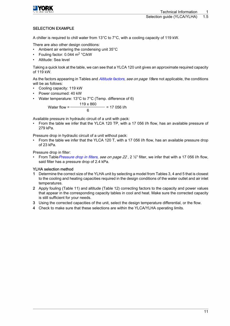
SELECTION EXAMPLE
A chiller is required to chill water from 13°C to 7°C, with a cooling capacity of 119 kW.
There are also other design conditions:• Ambient air entering the condensing unit 35°C• Fouling factor: 0.044 m2 °C/kW• Altitude: Sea level
Taking a quick look at the table, we can see that a YLCA 120 unit gives an approximate required capacityof 119 kW.
As the factors appearing in Tables and Altitude factors, see on page 18are not applicable, the conditionswill be as follows:• Cooling capacity: 119 kW• Power consumed: 40 kW• Water temperature: 13°C to 7°C (Temp. difference of 6)
Water flow =119 x 860
= 17 056 l/h6
Available pressure in hydraulic circuit of a unit with pack:• From the table we infer that the YLCA 120 TP, with a 17 056 l/h flow, has an available pressure of
279 kPa.
Pressure drop in hydraulic circuit of a unit without pack:• From the table we infer that the YLCA 120 T, with a 17 056 l/h flow, has an available pressure drop
of 23 kPa.
Pressure drop in filter:• From TablePressure drop in filters, see on page 22 , 2 ½" filter, we infer that with a 17 056 l/h flow,
said filter has a pressure drop of 2.4 kPa.
YLHA selection method1 Determine the correct size of the YLHA unit by selecting a model from Tables 3, 4 and 5 that is closest
to the cooling and heating capacities required in the design conditions of the water outlet and air inlettemperatures.
2 Apply fouling (Table 11) and altitude (Table 12) correcting factors to the capacity and power valuesthat appear in the corresponding capacity tables in cool and heat. Make sure the corrected capacityis still sufficient for your needs.
3 Using the corrected capacities of the unit, select the design temperature differential, or the flow.4 Check to make sure that these selections are within the YLCA/YLHA operating limits.
Technical Information 1Selection guide (YLCA/YLHA) 1.5
11
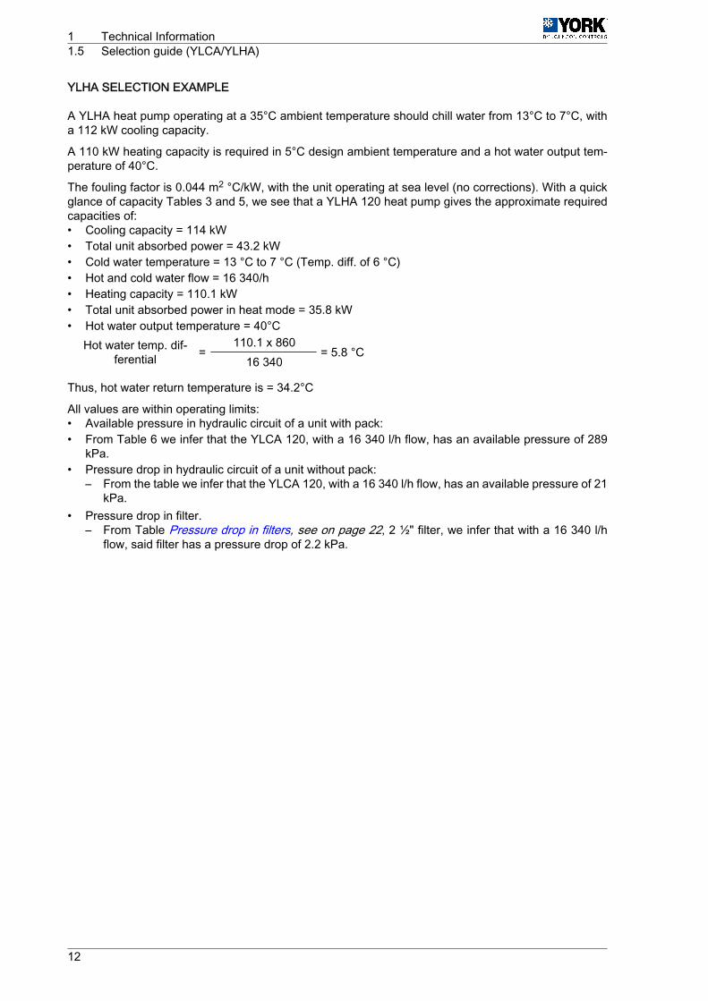
YLHA SELECTION EXAMPLE
A YLHA heat pump operating at a 35°C ambient temperature should chill water from 13°C to 7°C, witha 112 kW cooling capacity.
A 110 kW heating capacity is required in 5°C design ambient temperature and a hot water output tem‐perature of 40°C.
The fouling factor is 0.044 m2 °C/kW, with the unit operating at sea level (no corrections). With a quickglance of capacity Tables 3 and 5, we see that a YLHA 120 heat pump gives the approximate requiredcapacities of:• Cooling capacity = 114 kW• Total unit absorbed power = 43.2 kW• Cold water temperature = 13 °C to 7 °C (Temp. diff. of 6 °C)• Hot and cold water flow = 16 340/h• Heating capacity = 110.1 kW• Total unit absorbed power in heat mode = 35.8 kW• Hot water output temperature = 40°C
Hot water temp. dif‐ferential =
110.1 x 860= 5.8 °C
16 340
Thus, hot water return temperature is = 34.2°C
All values are within operating limits:• Available pressure in hydraulic circuit of a unit with pack:• From Table 6 we infer that the YLCA 120, with a 16 340 l/h flow, has an available pressure of 289
kPa.• Pressure drop in hydraulic circuit of a unit without pack:
– From the table we infer that the YLCA 120, with a 16 340 l/h flow, has an available pressure of 21kPa.
• Pressure drop in filter.– From Table Pressure drop in filters, see on page 22, 2 ½" filter, we infer that with a 16 340 l/h
flow, said filter has a pressure drop of 2.2 kPa.
1 Technical Information1.5 Selection guide (YLCA/YLHA)
12

1.5.1 Selection guide with glycol (cooling only units)Necessary informationThe following information is needed to select a YLCA water chiller:1 Cooling capacity needed2 Design cold water/glycol input and output temperatures.3 Design water/glycol flow.4 Design input temperature of air to condensing unit. Normally, this will be the design ambient temper‐
ature of summer air, unless influenced by the situation or other factors.5 Altitude above sea level.6 Design fouling factor of the evaporating unit.
N O T EPoints 1, 2 and 3 should be related by means of the following formulae:
Capacity (kW) =Temp. diff. (°C) x Flow (litres/sec.)
Glycol factor
Temp. diff. (°C) = Liquid inlet Temp. ‑ Liquid output Temp.
To determine the glycol factor, please see Glycol concentration and correcting tables, see on page16 (Recommended ethylene glycol concentrations) for ethylene glycol or (Recommended propyleneglycol concentrations) for propylene glycol. For design output temperature, please see the recommendedglycol concentration and the glycol factor in this concentration. This is the minimum concentration to beused for design output temperature. If a greater concentration is required, the glycol factor can be de‐termined by means of Glycol concentration and correcting tables, see on page 16 (Ethylene glycol inother concentrations) or (Propylene glycol in other concentrations).
Selection method1 Determine the correct chiller model by selecting the one that is closest to the capacities required by
the design conditions of the glycol outlet and air inlet temperatures.2 Apply the fouling correcting factors that correspond to the fouling, altitude and glycol concentration
factor, to the capacity and power values in the capacity tables. Make sure the corrected capacity isstill sufficient for your needs.
3 Using the corrected capacities of the chiller, set the design temperature range, or the flow, to balancethe formulae appearing in Selection guide (YLCA/YLHA), see on page 10.
4 Always recheck to make sure these selections are within the specified design limits.
Selection example
A chiller is required to chill ethylene glycol from 1 a to ‑4°, with a capacity of 75 kW.
The following design conditions are applicable:• Fouling factor: 0.088m °C/kW• Altitude: 1,200m• Ambient air: 25°C• Glycol concentration: 30% w/w
For a ‑4°C ethylene glycol output, the concentration recommended in Figure 1 is 30%. Therefore, thespecified concentration is appropriate.
From Table Cooling capacities YLCA 40 ÷ 150 (35% ethylene glycol), see on page 37, we infer that aYLCA-120 unit, at the established design conditions, gives a capacity of 76.8 kW and a consumption of28.8 kW.
With the design fouling factor, use the capacity correcting factors x 0.987 and power x 0.995 (see Foulingfactors, see on page 15).
On design altitude, apply the capacity correcting factors x 9.973 and power x 1.020 (see Altitude fac‐tors, see on page 18).
Technical Information 1Selection guide (YLCA/YLHA) 1.5
13
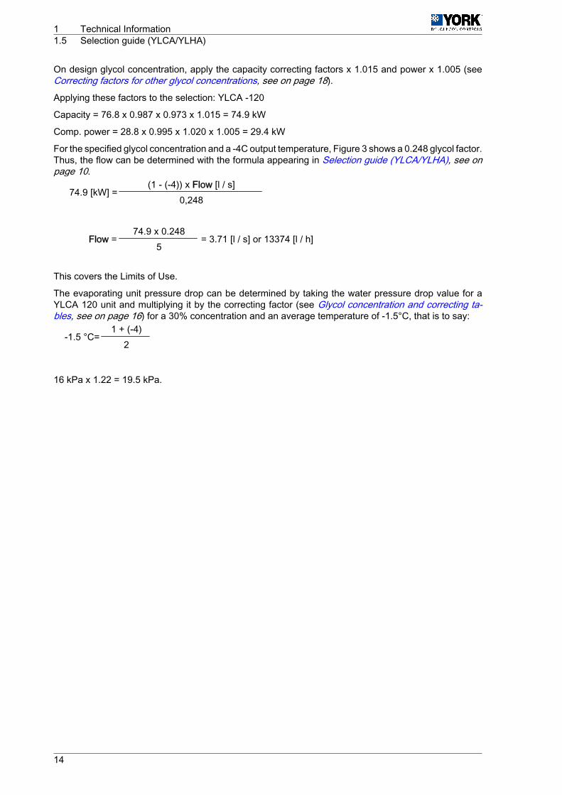
On design glycol concentration, apply the capacity correcting factors x 1.015 and power x 1.005 (seeCorrecting factors for other glycol concentrations, see on page 18).
Applying these factors to the selection: YLCA ‑120
Capacity = 76.8 x 0.987 x 0.973 x 1.015 = 74.9 kW
Comp. power = 28.8 x 0.995 x 1.020 x 1.005 = 29.4 kW
For the specified glycol concentration and a ‑4C output temperature, Figure 3 shows a 0.248 glycol factor.Thus, the flow can be determined with the formula appearing in Selection guide (YLCA/YLHA), see onpage 10.
74.9 [kW] =(1 ‑ (-4)) x Flow [l / s]
0,248
Flow =74.9 x 0.248
= 3.71 [l / s] or 13374 [l / h]5
This covers the Limits of Use.
The evaporating unit pressure drop can be determined by taking the water pressure drop value for aYLCA 120 unit and multiplying it by the correcting factor (see Glycol concentration and correcting ta‐bles, see on page 16) for a 30% concentration and an average temperature of ‑1.5°C, that is to say:
-1.5 °C=1 + (-4)
2
16 kPa x 1.22 = 19.5 kPa.
1 Technical Information1.5 Selection guide (YLCA/YLHA)
14
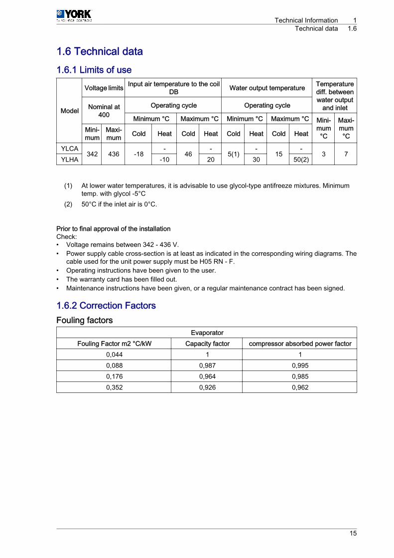
1.6 Technical data1.6.1 Limits of use
Model
Voltage limits Input air temperature to the coilDB Water output temperature Temperature
diff. betweenwater output
and inletNominal at400
Operating cycle Operating cycle
Minimum °C Maximum °C Minimum °C Maximum °C Mini‐mum°C
Maxi‐mum°C
Mini‐mum
Maxi‐mum Cold Heat Cold Heat Cold Heat Cold Heat
YLCA342 436 -18
-46
-5(1)
-15
-3 7
YLHA -10 20 30 50(2)
(1) At lower water temperatures, it is advisable to use glycol-type antifreeze mixtures. Minimumtemp. with glycol ‑5°C
(2) 50°C if the inlet air is 0°C.
Prior to final approval of the installationCheck:• Voltage remains between 342 ‑ 436 V.• Power supply cable cross-section is at least as indicated in the corresponding wiring diagrams. The
cable used for the unit power supply must be H05 RN ‑ F.• Operating instructions have been given to the user.• The warranty card has been filled out.• Maintenance instructions have been given, or a regular maintenance contract has been signed.
1.6.2 Correction FactorsFouling factors
EvaporatorFouling Factor m2 °C/kW Capacity factor compressor absorbed power factor
0,044 1 10,088 0,987 0,9950,176 0,964 0,9850,352 0,926 0,962
Technical Information 1Technical data 1.6
15
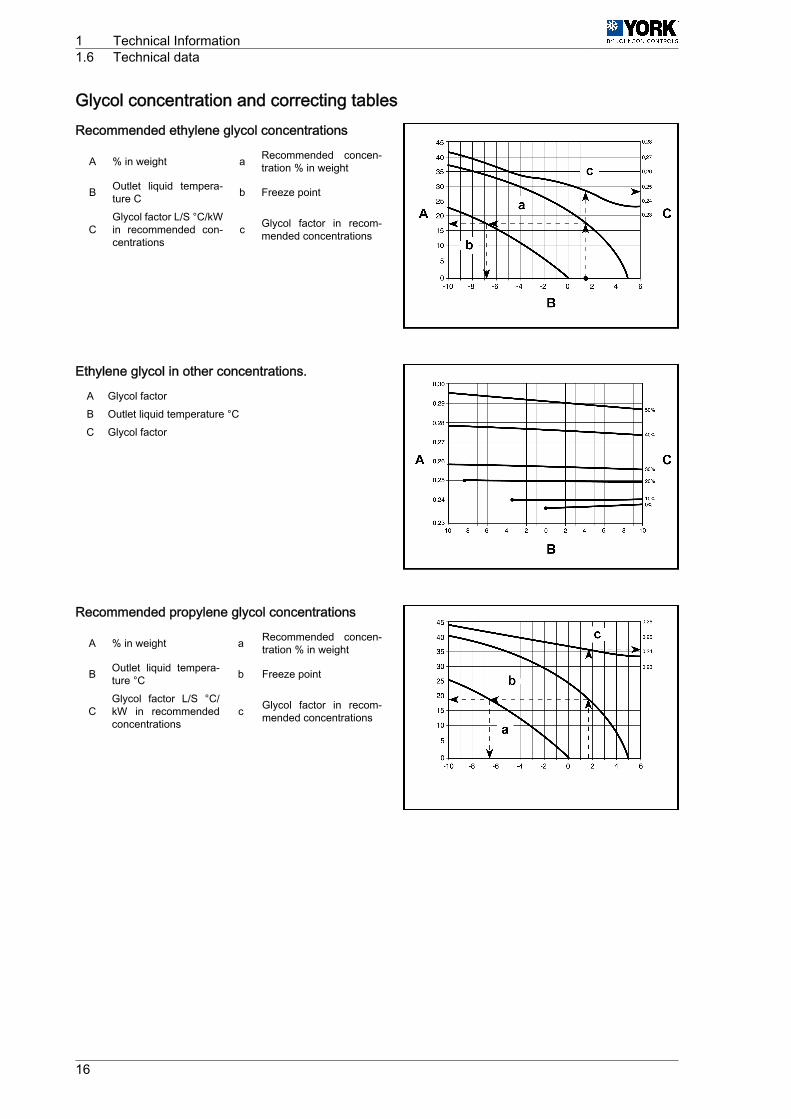
Glycol concentration and correcting tablesRecommended ethylene glycol concentrations
A % in weight a Recommended concen‐tration % in weight
B Outlet liquid tempera‐ture C b Freeze point
CGlycol factor L/S °C/kWin recommended con‐centrations
c Glycol factor in recom‐mended concentrations
Ethylene glycol in other concentrations.
A Glycol factorB Outlet liquid temperature °CC Glycol factor
Recommended propylene glycol concentrations
A % in weight a Recommended concen‐tration % in weight
B Outlet liquid tempera‐ture °C b Freeze point
CGlycol factor L/S °C/kW in recommendedconcentrations
c Glycol factor in recom‐mended concentrations
1 Technical Information1.6 Technical data
16
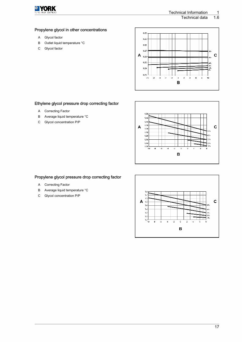
Propylene glycol in other concentrations
A Glycol factorB Outlet liquid temperature °CC Glycol factor
Ethylene glycol pressure drop correcting factor
A Correcting FactorB Average liquid temperature °CC Glycol concentration P/P
Propylene glycol pressure drop correcting factor
A Correcting FactorB Average liquid temperature °CC Glycol concentration P/P
Technical Information 1Technical data 1.6
17
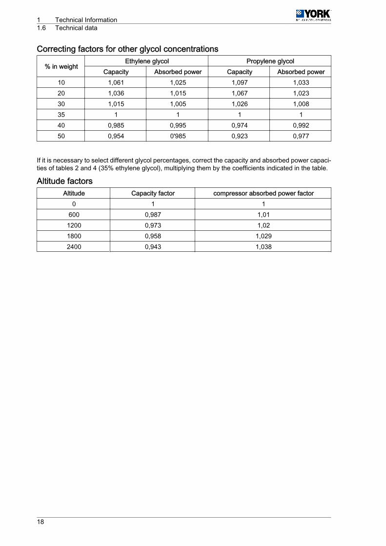
Correcting factors for other glycol concentrations
% in weightEthylene glycol Propylene glycol
Capacity Absorbed power Capacity Absorbed power10 1,061 1,025 1,097 1,03320 1,036 1,015 1,067 1,02330 1,015 1,005 1,026 1,00835 1 1 1 140 0,985 0,995 0,974 0,99250 0,954 0'985 0,923 0,977
If it is necessary to select different glycol percentages, correct the capacity and absorbed power capaci‐ties of tables 2 and 4 (35% ethylene glycol), multiplying them by the coefficients indicated in the table.
Altitude factorsAltitude Capacity factor compressor absorbed power factor
0 1 1600 0,987 1,01
1200 0,973 1,021800 0,958 1,0292400 0,943 1,038
1 Technical Information1.6 Technical data
18
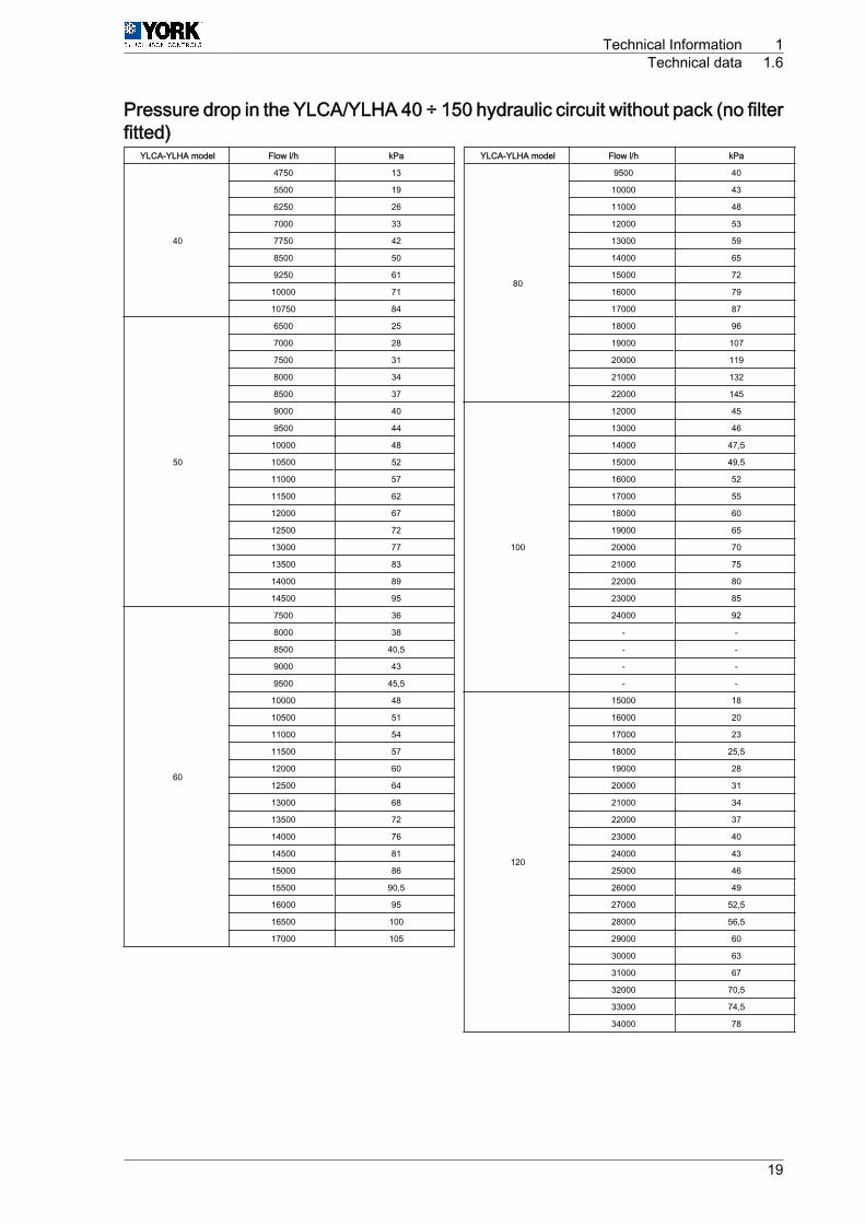
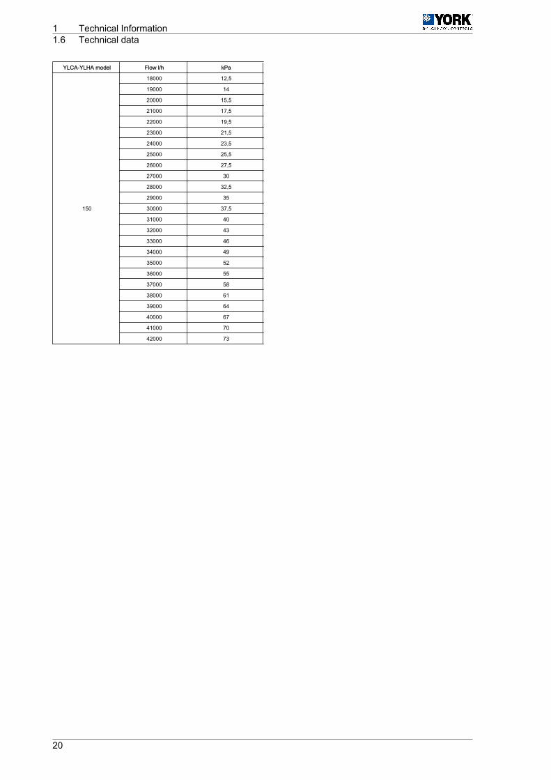
Pressure drop in the YLCA/YLHA 40 ÷ 150 hydraulic circuit without pack (no filterfitted)
YLCA-YLHA model Flow l/h kPa
40
4750 13
5500 19
6250 26
7000 33
7750 42
8500 50
9250 61
10000 71
10750 84
50
6500 25
7000 28
7500 31
8000 34
8500 37
9000 40
9500 44
10000 48
10500 52
11000 57
11500 62
12000 67
12500 72
13000 77
13500 83
14000 89
14500 95
60
7500 36
8000 38
8500 40,5
9000 43
9500 45,5
10000 48
10500 51
11000 54
11500 57
12000 60
12500 64
13000 68
13500 72
14000 76
14500 81
15000 86
15500 90,5
16000 95
16500 100
17000 105
YLCA-YLHA model Flow l/h kPa
80
9500 40
10000 43
11000 48
12000 53
13000 59
14000 65
15000 72
16000 79
17000 87
18000 96
19000 107
20000 119
21000 132
22000 145
100
12000 45
13000 46
14000 47,5
15000 49,5
16000 52
17000 55
18000 60
19000 65
20000 70
21000 75
22000 80
23000 85
24000 92
- -
- -
- -
- -
120
15000 18
16000 20
17000 23
18000 25,5
19000 28
20000 31
21000 34
22000 37
23000 40
24000 43
25000 46
26000 49
27000 52,5
28000 56,5
29000 60
30000 63
31000 67
32000 70,5
33000 74,5
34000 78
Technical Information 1Technical data 1.6
19
YLCA-YLHA model Flow l/h kPa
150
18000 12,5
19000 14
20000 15,5
21000 17,5
22000 19,5
23000 21,5
24000 23,5
25000 25,5
26000 27,5
27000 30
28000 32,5
29000 35
30000 37,5
31000 40
32000 43
33000 46
34000 49
35000 52
36000 55
37000 58
38000 61
39000 64
40000 67
41000 70
42000 73
1 Technical Information1.6 Technical data
20
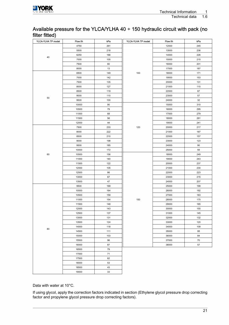
Available pressure for the YLCA/YLHA 40 ÷ 150 hydraulic circuit with pack (nofilter fitted)
YLCA-YLHA TP model Flow l/h kPa
40
4750 261
5500 218
6250 166
7000 105
7500 60
8000 13
50
6500 149
7000 142
7500 135
8000 127
8500 119
9000 110
9500 100
10000 90
10500 79
11000 68
11500 56
12000 44
60
7500 233
8000 222
8500 210
9000 198
9500 185
10000 172
10500 156
11000 140
11500 122
12000 105
12500 86
13000 67
13500 47
80
9500 169
10000 164
10500 159
11000 154
11500 148
12000 143
12500 137
13000 131
13500 124
14000 118
14500 111
15000 103
15500 96
16000 87
16500 79
17000 71
17500 62
18000 53
18500 43
19000 33
YLCA-YLHA TP model Flow l/h kPa
100
12000 245
13000 236
14000 226
15000 215
16000 201
17000 187
18000 171
19000 153
20000 131
21000 110
22000 87
23000 57
24000 32
120
15000 310
16000 295
17000 279
18000 261
19000 241
20000 217
21000 187
22000 157
23000 123
24000 90
25000 55
150
18000 249
19000 243
20000 237
21000 230
22000 223
23000 215
24000 207
25000 199
26000 192
27000 183
28000 175
29000 165
30000 155
31000 145
32000 132
33000 120
34000 109
35000 95
36000 84
37000 70
38000 57
Data with water at 10°C.
If using glycol, apply the correction factors indicated in section (Ethylene glycol pressure drop correctingfactor and propylene glycol pressure drop correcting factors).
Technical Information 1Technical data 1.6
21
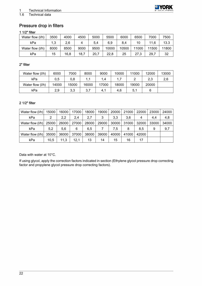
Pressure drop in filters1 1/2" filter
Water flow (l/h) 3500 4000 4500 5000 5500 6000 6500 7000 7500kPa 1,3 2,6 4 5,4 6,9 8,4 10 11,6 13.3
Water flow (l/h) 8000 8500 9000 9500 10000 10500 11000 11500 11800kPa 15 16,8 18,7 20,7 22,8 25 27,3 29,7 32
2" filter
Water flow (l/h) 6000 7000 8000 9000 10000 11000 12000 13000kPa 0,5 0,8 1,1 1,4 1,7 2 2,3 2,6
Water flow (l/h) 14000 15000 16000 17000 18000 19000 20000 kPa 2,9 3,3 3,7 4,1 4,6 5,1 6
2 1/2" filter
Water flow (l/h) 15000 16000 17000 18000 19000 20000 21000 22000 23000 24000kPa 2 2,2 2,4 2,7 3 3,3 3,6 4 4,4 4,8
Water flow (l/h) 25000 26000 27000 28000 29000 30000 31000 32000 33000 34000kPa 5,2 5,6 6 6,5 7 7,5 8 8,5 9 9,7
Water flow (l/h) 35000 36000 37000 38000 39000 40000 41000 42000 kPa 10,5 11,3 12,1 13 14 15 16 17
Data with water at 10°C.
If using glycol, apply the correction factors indicated in section (Ethylene glycol pressure drop correctingfactor and propylene glycol pressure drop correcting factors).
1 Technical Information1.6 Technical data
22

1.6.3 Physical dataPhysical data, YLCA unitsPhysical data
YLCA (T and TP)
Characteristics 40 50 60 80 100 120 150
Cooling capacity kW 39,6 52,1 60,5 72,6 101 119 151
Capacity control % 100 50-100 25-50-75-100
Power supply V/ph 400.3.50
EER/OOP 3 2,9 3,1 2,9 2,9 2,9 2,8
Compressor
Compressor consumption kW 12,46 2 x 8.5 2 x 9.2 2 x 12.4 4 x 7.8 4 x 9.4 4 x 12.5
Compressor amperage A 23,5 2 x 15.5 2 x 16.7 2 x 24.6 4 x 16 4 x 17.7 4 x 23.5
No. of compressors 1 2 (1 Tandem) 4 (2 tandem)
Compressor type SCROLL
Oil charge l 3,25 2 x 3.25 4 x 3.25
Oil type POLYOL ESTER OIL
Evaporating unit type PLATES
Fan
No. of fans 2 3 4
Fan diameter mm 560 630 710
Fan consumption W 2 x 400 2 x 600 3 x 600 4 x 600 4 x 860
Fan amperage A 2 x 1.9 2 x 2.8 3 x 2.8 4 x 2.8 4 x 3.9
Total air flow m³/h 12300 18600 27500 36000 48000
Sound power (standard / Lownoise) dB(A) 81 / 76 83 / 78 85 / 80 86 / 82 86 / 82 86 / 82 87 / 83
Sound pressure at 5 m(standard / Low noise) dB(A) 60 / 54 62 / 56 63 / 57 66 / 60 63 / 60 64 / 60 65 / 61
Sound pressure at 10 m(standard / Low noise) dB(A) 54 / 48 56 / 50 57 / 51 60 / 54 57 / 54 58 / 54 59 / 55
Refrigerant
Refrigerant type R-410A
Refrigerant charge kg 11 13 16 25 2 x 16.5 2 x 16.2 2 x 21
No. of refrigerant circuits 1 2
Water circuit
Nominal water flow l/h 6820 8960 10400 13350 17600 20470 25970
Water connection, female 1 1/4" 2" 2 1/2”
water filter, female 1 1/2" 2" 2 1/2"
Dimensions
Length mm 1500 2104 2944 3416 3770
Width mm 822 1011 1118 1101
Height mm 1573 1600 2190 2263
Units with hydro kit (version P)
YLCA (Version P)
Characteristics 40 50 60 80 100 120 150
No. of pumps 1
Available static pressure at nominal flow(without filter)(2) kPa 115 110 160 126 190 205 192
Available static pressure at nominal flow(without filter)(3) kPa 105 108 158 123 187 202 186
Pump consumption W 1035 990 1515 1620 2395 3180 3400
Pump amperage A 1,9 1,8 2,9 3,3 4,4 5,5 6,1
Unit water content l 131 188 194 285 193 195 214
Expansion vessel volume l 12 18 25 35
Tank capacity l 115 170 260 152
Safety valve setting MPa(bar)
0,6(6)
Max. unit power supply consumption kW 18,23 24,6 26,3 35,2 52,4 56,2 70,7
Max. unit current amperage A 33 46,2 49,2 70,5 95,4 108 124
Start-up current (compressor) A 174 118 118 174 118 118 174
Weight (1) kg 380 580 611 785 1220 1286 1503
Technical Information 1Technical data 1.6
23
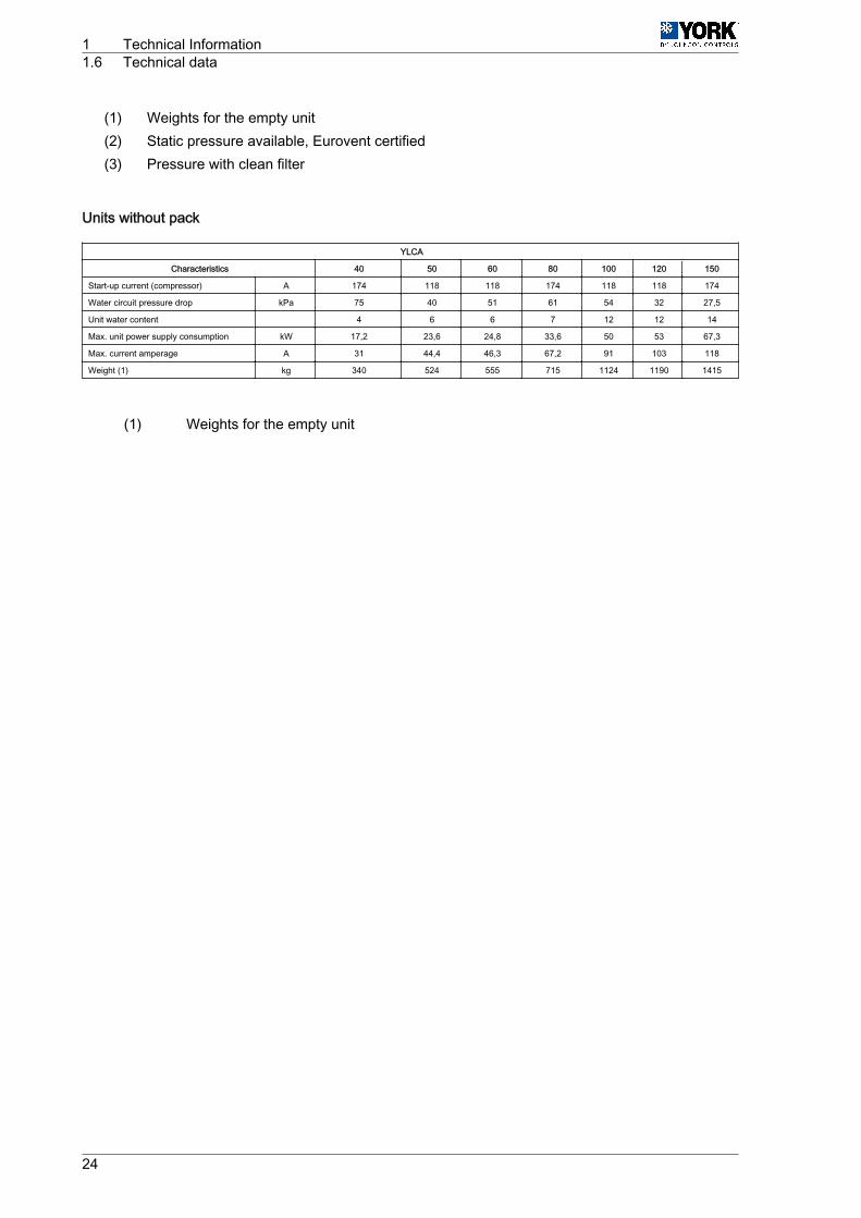
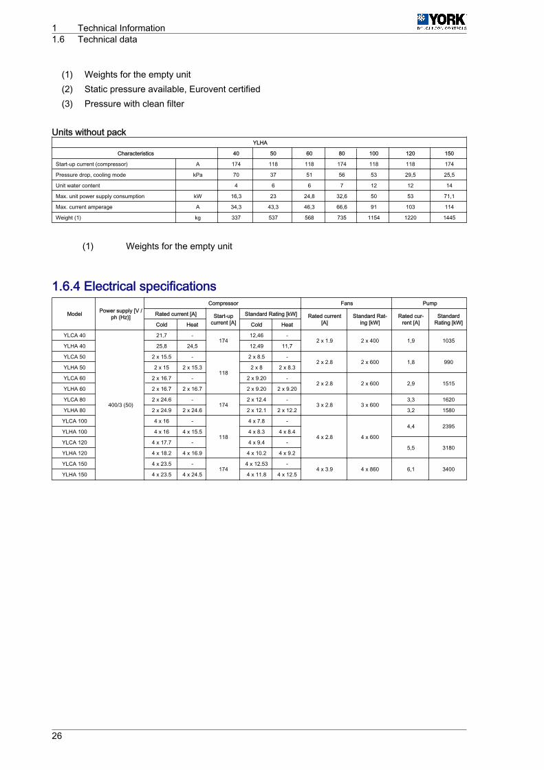
(1) Weights for the empty unit(2) Static pressure available, Eurovent certified(3) Pressure with clean filter
Units without pack
YLCA
Characteristics 40 50 60 80 100 120 150
Start-up current (compressor) A 174 118 118 174 118 118 174
Water circuit pressure drop kPa 75 40 51 61 54 32 27,5
Unit water content 4 6 6 7 12 12 14
Max. unit power supply consumption kW 17,2 23,6 24,8 33,6 50 53 67,3
Max. current amperage A 31 44,4 46,3 67,2 91 103 118
Weight (1) kg 340 524 555 715 1124 1190 1415
(1) Weights for the empty unit
1 Technical Information1.6 Technical data
24
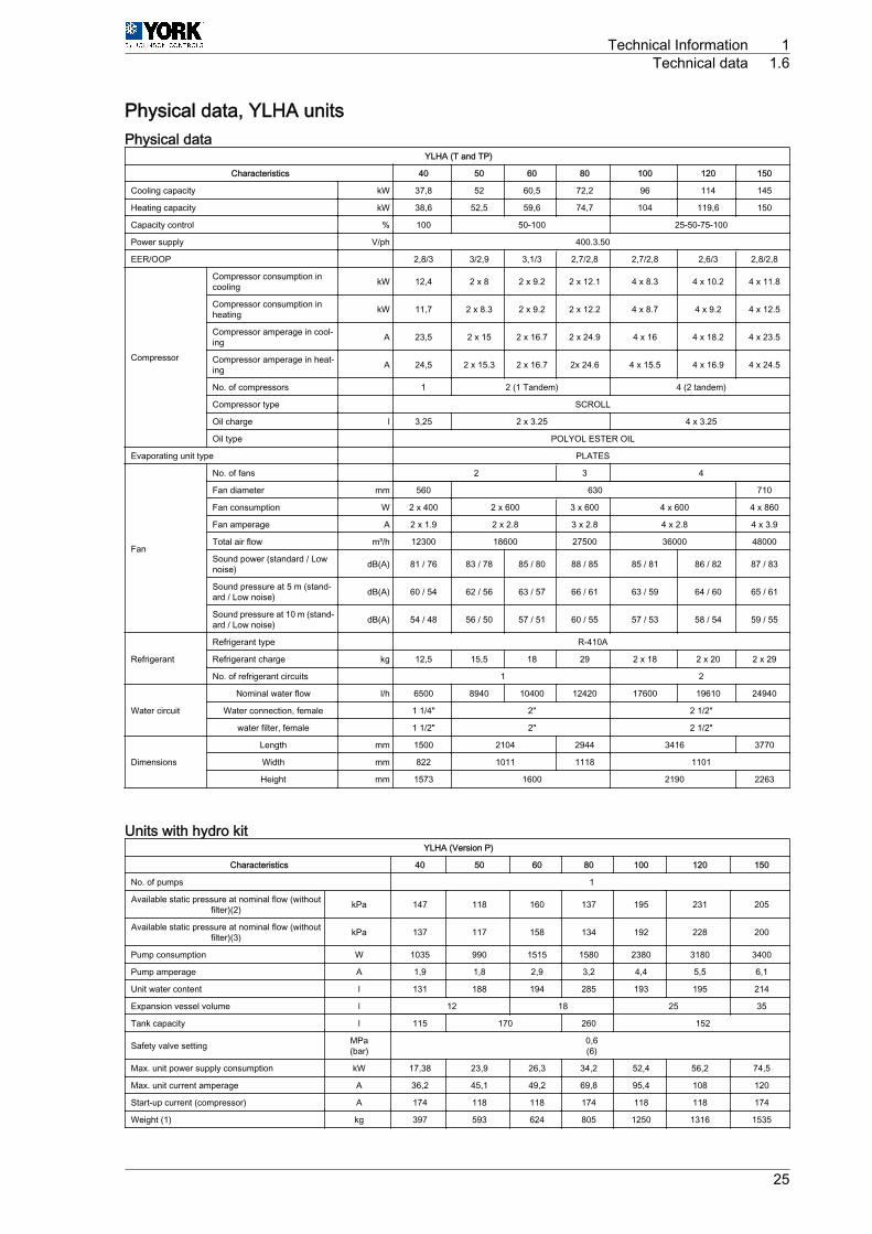
Physical data, YLHA unitsPhysical data
YLHA (T and TP)
Characteristics 40 50 60 80 100 120 150
Cooling capacity kW 37,8 52 60,5 72,2 96 114 145
Heating capacity kW 38,6 52,5 59,6 74,7 104 119,6 150
Capacity control % 100 50-100 25-50-75-100
Power supply V/ph 400.3.50
EER/OOP 2,8/3 3/2,9 3,1/3 2,7/2,8 2,7/2,8 2,6/3 2,8/2,8
Compressor
Compressor consumption incooling kW 12,4 2 x 8 2 x 9.2 2 x 12.1 4 x 8.3 4 x 10.2 4 x 11.8
Compressor consumption inheating kW 11,7 2 x 8.3 2 x 9.2 2 x 12.2 4 x 8.7 4 x 9.2 4 x 12.5
Compressor amperage in cool‐ing A 23,5 2 x 15 2 x 16.7 2 x 24.9 4 x 16 4 x 18.2 4 x 23.5
Compressor amperage in heat‐ing A 24,5 2 x 15.3 2 x 16.7 2x 24.6 4 x 15.5 4 x 16.9 4 x 24.5
No. of compressors 1 2 (1 Tandem) 4 (2 tandem)
Compressor type SCROLL
Oil charge l 3,25 2 x 3.25 4 x 3.25
Oil type POLYOL ESTER OIL
Evaporating unit type PLATES
Fan
No. of fans 2 3 4
Fan diameter mm 560 630 710
Fan consumption W 2 x 400 2 x 600 3 x 600 4 x 600 4 x 860
Fan amperage A 2 x 1.9 2 x 2.8 3 x 2.8 4 x 2.8 4 x 3.9
Total air flow m³/h 12300 18600 27500 36000 48000
Sound power (standard / Lownoise) dB(A) 81 / 76 83 / 78 85 / 80 88 / 85 85 / 81 86 / 82 87 / 83
Sound pressure at 5 m (stand‐ard / Low noise) dB(A) 60 / 54 62 / 56 63 / 57 66 / 61 63 / 59 64 / 60 65 / 61
Sound pressure at 10 m (stand‐ard / Low noise) dB(A) 54 / 48 56 / 50 57 / 51 60 / 55 57 / 53 58 / 54 59 / 55
Refrigerant
Refrigerant type R-410A
Refrigerant charge kg 12,5 15,5 18 29 2 x 18 2 x 20 2 x 29
No. of refrigerant circuits 1 2
Water circuit
Nominal water flow l/h 6500 8940 10400 12420 17600 19610 24940
Water connection, female 1 1/4" 2" 2 1/2"
water filter, female 1 1/2" 2" 2 1/2"
Dimensions
Length mm 1500 2104 2944 3416 3770
Width mm 822 1011 1118 1101
Height mm 1573 1600 2190 2263
Units with hydro kitYLHA (Version P)
Characteristics 40 50 60 80 100 120 150
No. of pumps 1
Available static pressure at nominal flow (withoutfilter)(2) kPa 147 118 160 137 195 231 205
Available static pressure at nominal flow (withoutfilter)(3) kPa 137 117 158 134 192 228 200
Pump consumption W 1035 990 1515 1580 2380 3180 3400
Pump amperage A 1,9 1,8 2,9 3,2 4,4 5,5 6,1
Unit water content l 131 188 194 285 193 195 214
Expansion vessel volume l 12 18 25 35
Tank capacity l 115 170 260 152
Safety valve setting MPa(bar)
0,6(6)
Max. unit power supply consumption kW 17,38 23,9 26,3 34,2 52,4 56,2 74,5
Max. unit current amperage A 36,2 45,1 49,2 69,8 95,4 108 120
Start-up current (compressor) A 174 118 118 174 118 118 174
Weight (1) kg 397 593 624 805 1250 1316 1535
Technical Information 1Technical data 1.6
25
(1) Weights for the empty unit(2) Static pressure available, Eurovent certified(3) Pressure with clean filter
Units without packYLHA
Characteristics 40 50 60 80 100 120 150
Start-up current (compressor) A 174 118 118 174 118 118 174
Pressure drop, cooling mode kPa 70 37 51 56 53 29,5 25,5
Unit water content 4 6 6 7 12 12 14
Max. unit power supply consumption kW 16,3 23 24,8 32,6 50 53 71,1
Max. current amperage A 34,3 43,3 46,3 66,6 91 103 114
Weight (1) kg 337 537 568 735 1154 1220 1445
(1) Weights for the empty unit
1.6.4 Electrical specifications
Model Power supply [V /ph (Hz)]
Compressor Fans Pump
Rated current [A] Start-upcurrent [A]
Standard Rating [kW] Rated current[A]
Standard Rat‐ing [kW]
Rated cur‐rent [A]
StandardRating [kW]Cold Heat Cold Heat
YLCA 40
400/3 (50)
21,7 -174
12,46 -2 x 1.9 2 x 400 1,9 1035
YLHA 40 25,8 24,5 12,49 11,7
YLCA 50 2 x 15.5 -
118
2 x 8.5 -2 x 2.8 2 x 600 1,8 990
YLHA 50 2 x 15 2 x 15.3 2 x 8 2 x 8.3
YLCA 60 2 x 16.7 - 2 x 9.20 -2 x 2.8 2 x 600 2,9 1515
YLHA 60 2 x 16.7 2 x 16.7 2 x 9.20 2 x 9.20
YLCA 80 2 x 24.6 -174
2 x 12.4 -3 x 2.8 3 x 600
3,3 1620
YLHA 80 2 x 24.9 2 x 24.6 2 x 12.1 2 x 12.2 3,2 1580
YLCA 100 4 x 16 -
118
4 x 7.8 -
4 x 2.8 4 x 600
4,4 2395YLHA 100 4 x 16 4 x 15.5 4 x 8.3 4 x 8.4
YLCA 120 4 x 17.7 - 4 x 9.4 -5,5 3180
YLHA 120 4 x 18.2 4 x 16.9 4 x 10.2 4 x 9.2
YLCA 150 4 x 23.5 -174
4 x 12.53 -4 x 3.9 4 x 860 6,1 3400
YLHA 150 4 x 23.5 4 x 24.5 4 x 11.8 4 x 12.5
1 Technical Information1.6 Technical data
26
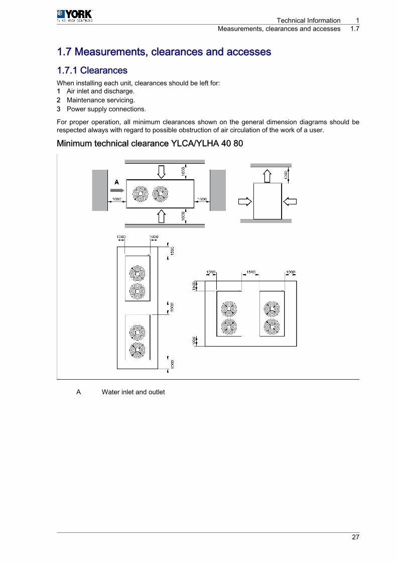
1.7 Measurements, clearances and accesses1.7.1 ClearancesWhen installing each unit, clearances should be left for:1 Air inlet and discharge.2 Maintenance servicing.3 Power supply connections.
For proper operation, all minimum clearances shown on the general dimension diagrams should berespected always with regard to possible obstruction of air circulation of the work of a user.
Minimum technical clearance YLCA/YLHA 40 80
A Water inlet and outlet
Technical Information 1Measurements, clearances and accesses 1.7
27
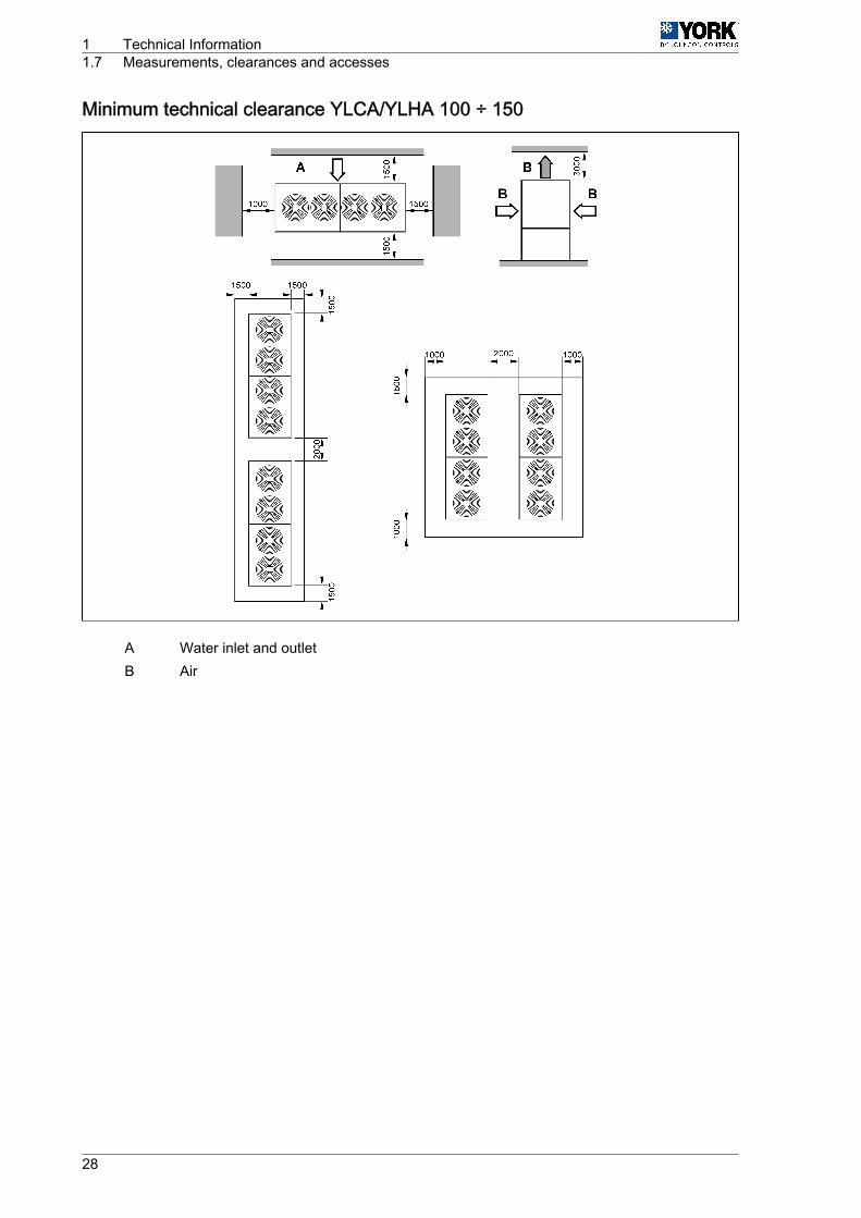
Minimum technical clearance YLCA/YLHA 100 ÷ 150
A Water inlet and outletB Air
1 Technical Information1.7 Measurements, clearances and accesses
28
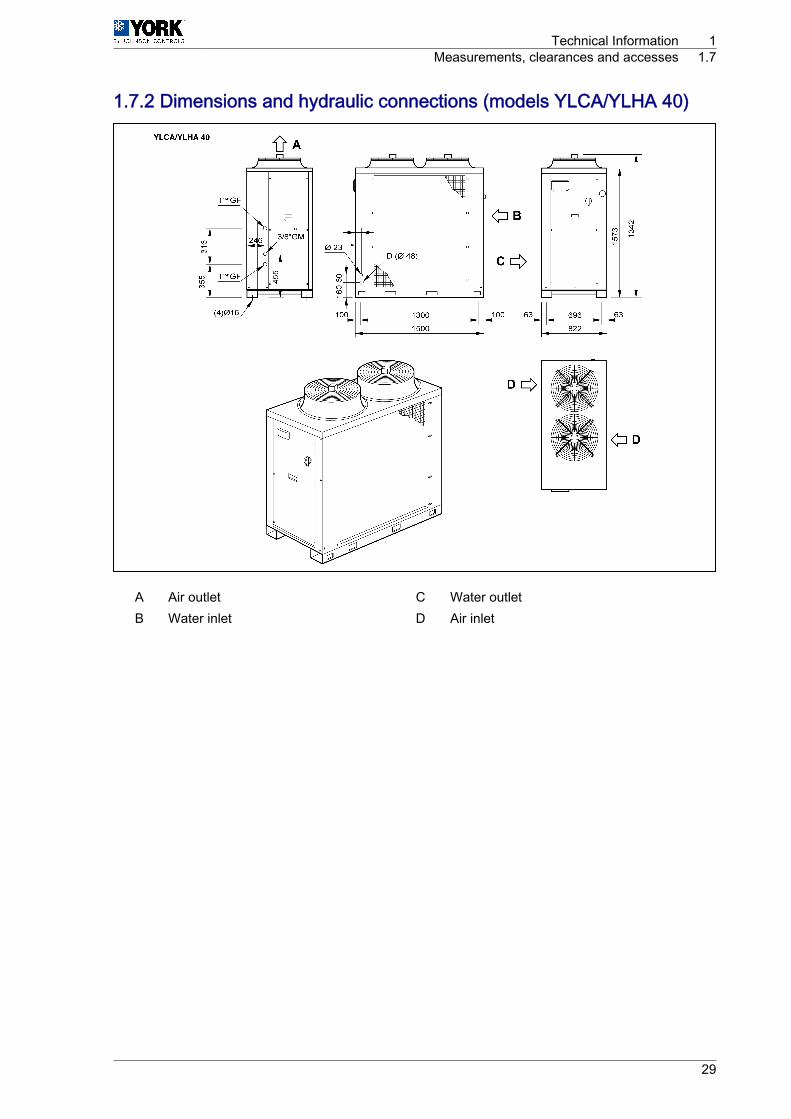
1.7.2 Dimensions and hydraulic connections (models YLCA/YLHA 40)
A Air outlet C Water outletB Water inlet D Air inlet
Technical Information 1Measurements, clearances and accesses 1.7
29
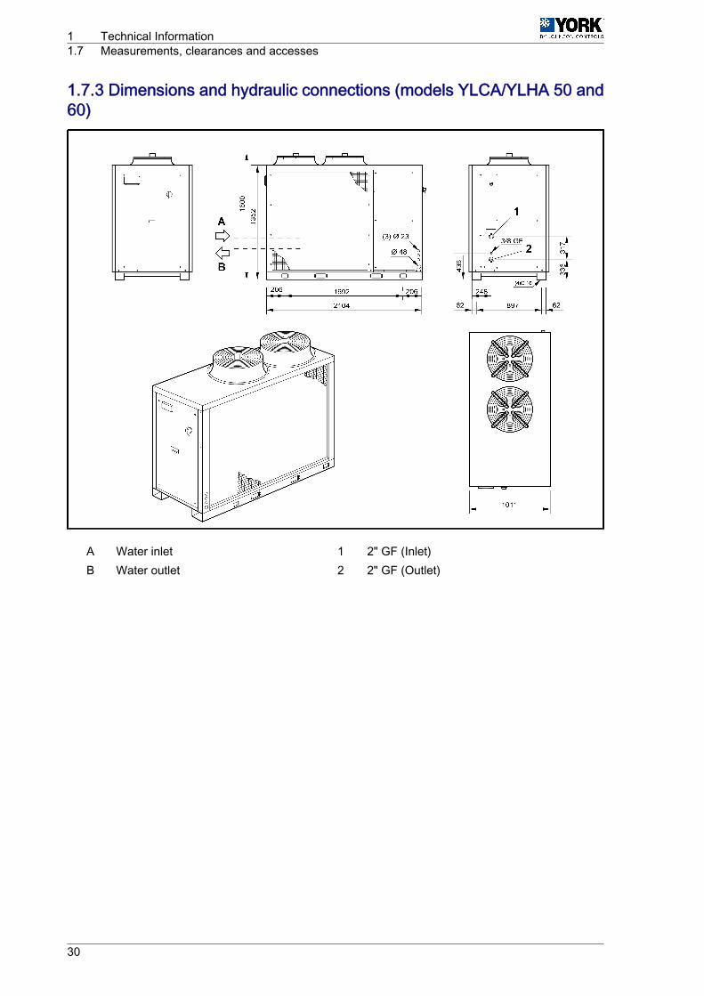
1.7.3 Dimensions and hydraulic connections (models YLCA/YLHA 50 and60)
A Water inlet 1 2" GF (Inlet)B Water outlet 2 2" GF (Outlet)
1 Technical Information1.7 Measurements, clearances and accesses
30
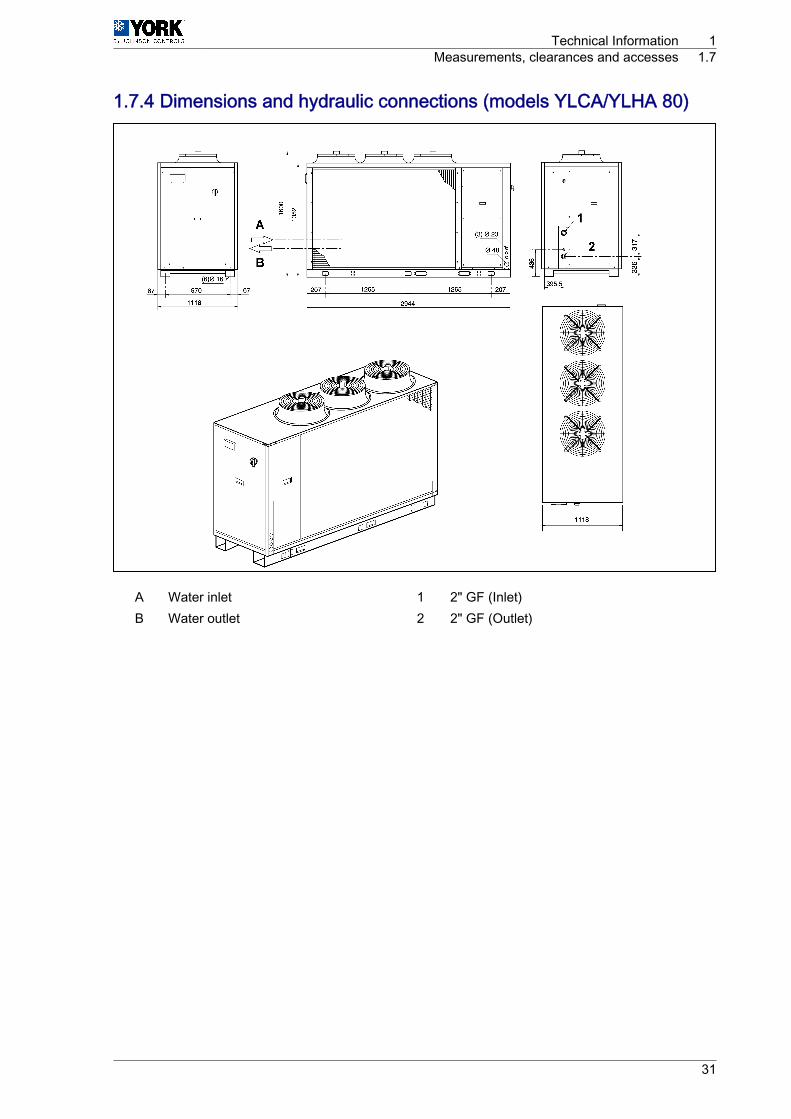
1.7.4 Dimensions and hydraulic connections (models YLCA/YLHA 80)
A Water inlet 1 2" GF (Inlet)B Water outlet 2 2" GF (Outlet)
Technical Information 1Measurements, clearances and accesses 1.7
31
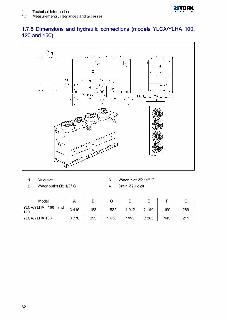
1.7.5 Dimensions and hydraulic connections (models YLCA/YLHA 100,120 and 150)
1 Air outlet 3 Water inlet Ø2 1/2" G2 Water outlet Ø2 1/2" G 4 Drain Ø20 x 20
Model A B C D E F GYLCA/YLHA 100 and120 3 416 183 1 525 1 942 2 190 199 289
YLCA/YLHA 150 3 770 255 1 630 1993 2 263 145 211
1 Technical Information1.7 Measurements, clearances and accesses
32
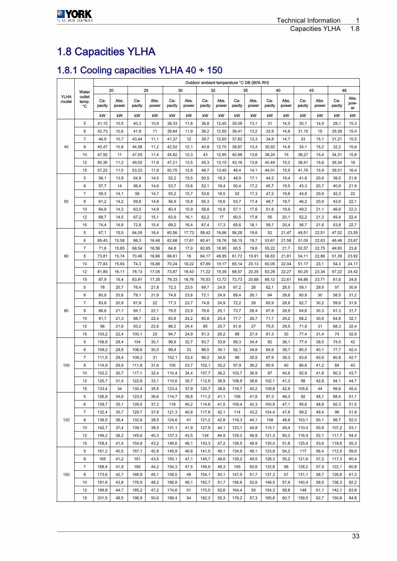
1.8 Capacities YLHA1.8.1 Cooling capacities YLHA 40 ÷ 150
YLHAmodel
Wateroutlettemp.
°C
Outdoor ambient temperature °C DB (80% RH)
20 25 30 32 35 40 43 46
Ca‐pacity
Abs.power
Ca‐pacity
Abs.power
Ca‐pacity
Abs.power
Ca‐pacity
Abs.power
Ca‐pacity
Abs.power
Ca‐pacity
Abs.power
Ca‐pacity
Abs.power
Ca‐pacity
Abs.pow‐
er
kW kW kW kW kW kW kW kW kW kW kW kW kW kW kW kW
40
5 41,15 10,5 40,3 10,9 38,33 11,8 36,8 12,45 35,08 13,1 31 14,5 30,1 14,9 29,1 15,3
6 42,73 10,6 41,8 11 39,84 11,9 38,2 12,55 36,41 13,2 32,9 14,6 31,15 15 29,38 15,4
7 44,9 10,7 43,44 11,1 41,37 12 39,7 12,65 37,82 13,3 34,8 14,7 33 15,1 31,21 15,5
8 45,47 10,8 44,58 11,2 42,52 12,1 40,8 12,75 38,87 13,4 35,92 14,8 34,1 15,2 32,2 15,6
10 47,92 11 47,05 11,4 44,82 12,3 43 12,95 40,98 13,6 38,24 15 36,27 15,4 34,31 15,8
12 50,36 11,2 49,52 11,6 47,21 12,5 45,3 13,15 43,16 13,8 40,49 15,2 38,41 15,6 36,34 16
15 57,22 11,5 53,23 11,9 50,75 12,8 48,7 13,45 46,4 14,1 44,01 15,5 41,76 15,9 39,51 16,4
50
5 56,1 13,9 54,9 14,5 52,2 15,5 50,5 16,3 48,9 17,1 44,2 19,4 41,8 20,6 39,5 21,8
6 57,7 14 56,4 14,6 53,7 15,6 52,1 16,4 50,4 17,2 45,7 19,5 43,3 20,7 40,9 21,9
7 59,3 14,1 58 14,7 55,2 15,7 53,6 16,5 52 17,3 47,2 19,6 44,8 20,8 42,3 22
8 61,2 14,2 59,8 14,8 56,9 15,8 55,3 16,6 53,7 17,4 48,7 19,7 46,2 20,9 43,8 22,1
10 64,9 14,3 63,5 14,9 60,4 15,9 58,8 16,8 57,1 17,6 51,8 19,9 49,2 21,1 46,6 22,3
12 68,7 14,5 67,2 15,1 63,9 16,1 62,2 17 60,5 17,8 55 20,1 52,2 21,3 49,4 22,4
15 74,4 14,8 72,8 15,4 69,2 16,4 67,4 17,3 65,6 18,1 59,7 20,4 56,7 21,6 53,8 22,7
60
5 67,1 15,5 64,05 16,4 60,56 17,73 58,42 18,66 56,28 19,6 52 21,47 49,51 22,51 47,02 23,55
6 69,45 15,58 66,3 16,48 62,68 17,81 60,41 18,76 58,15 19,7 53,61 21,58 51,05 22,63 48,48 23,67
7 71,8 15,65 68,54 16,56 64,8 17,9 62,65 18,95 60,5 19,6 55,22 21,7 52,57 22,75 49,93 23,8
8 73,81 15,74 70,46 16,66 66,61 18 64,17 48,95 61,72 19,91 56,83 21,81 54,11 22,86 51,39 23,92
10 77,83 15,93 74,3 16,86 70,24 18,22 67,69 19,17 65,14 20,13 60,05 22,04 51,17 23,1 54,3 24,17
12 81,85 16,11 78,13 17,05 73,87 18,43 71,22 19,39 68,57 20,35 63,28 22,27 60,25 23,34 57,22 24,42
15 87,9 16,4 83,91 17,35 79,33 18,76 76,53 12,72 73,73 20,68 68,12 22,61 64,86 23,71 61,6 24,8
80
5 78 20,7 76,4 21,8 72,3 23,5 69,7 24,8 67,2 26 62,1 28,5 59,1 29,9 57 30,9
6 80,9 20,8 79,1 21,9 74,8 23,6 72,1 24,9 69,4 26,1 64 28,6 60,9 30 58,5 31,2
7 83,8 20,9 81,8 22 77,3 23,7 74,8 24,9 72,2 26 65,9 28,8 62,7 30,2 59,6 31,6
8 86,6 21,1 84,1 22,1 79,5 23,9 76,6 25,1 73,7 26,4 67,8 28,9 64,6 30,3 61,3 31,7
10 91,7 21,3 88,7 22,4 83,8 24,2 80,8 25,4 77,7 26,7 71,7 29,2 68,2 30,6 64,8 32,1
12 96 21,6 93,2 22,6 88,2 24,4 85 25,7 81,8 27 75,5 29,5 71,9 31 68,3 32,4
15 103,2 22,4 100,1 23 94,7 24,9 91,3 26,2 88 27,4 81,3 30 77,4 31,4 74 32,9
100
5 106,8 28,4 104 30,1 96,6 32,7 93,7 33,8 89,3 34,4 82 38,1 77,4 39,5 74,5 42
6 109,2 28,9 106,6 30,5 99,4 33 96,5 34,1 92,1 34,8 84,9 38,7 80,5 40,1 77,7 42,4
7 111,5 29,4 109,2 31 102,1 33,4 99,2 34,6 96 35,5 87,9 39,3 83,6 40,6 80,8 42,7
8 114,9 29,9 111,8 31,6 105 33,7 102,1 35,2 97,9 36,2 90,9 40 86,8 41,2 84 43
10 102,2 30,7 117,1 32,4 110,4 34,4 107,7 36,2 103,7 36,9 97 40,6 92,9 41,8 90,3 43,7
12 125,7 31,4 122,6 33,1 115,6 35,7 112,9 36,9 108,8 38,6 102,1 41,3 98 42,8 94,1 44,7
15 133,4 34 130,4 35,5 123,4 37,9 120,7 38,8 116,7 40,2 109,8 42,6 105,6 44 99,8 45,4
120
5 126,8 34,6 123,5 36,6 114,7 39,8 111,2 41,1 106 41,9 97,3 46,3 92 48,1 88,4 51,1
6 129,7 35,1 126,5 37,2 118 40,2 114,6 41,5 109,4 42,3 100,9 47,1 95,6 48,8 92,3 51,5
7 132,4 35,7 129,7 37,8 121,3 40,6 117,8 42,1 114 43,2 104,4 47,8 99,2 49,4 96 51,9
8 136,5 36,4 132,8 38,5 124,6 41 121,2 42,8 116,3 44,1 108 48,6 103,1 50,1 99,7 52,3
10 142,7 37,4 139,1 39,5 131,1 41,9 127,9 44,1 123,1 44,9 115,1 49,4 110,4 50,8 107,2 53,1
12 149,2 38,2 145,6 40,3 137,3 43,5 134 44,9 129,2 46,9 121,3 50,2 116,4 52,1 111,7 54,4
15 158,4 41,4 154,8 43,2 146,6 46,1 143,3 47,2 138,5 48,9 130,4 51,8 125,4 53,6 118,6 55,3
150
5 161,2 40,5 157,1 42,8 145,9 46,6 141,5 48,1 134,9 49,1 123,8 54,2 117 56,4 112,5 59,9
6 165 41,2 161 43,5 150,1 47,1 145,7 48,6 139,2 49,5 128,3 55,2 121,6 57,2 117,3 60,4
7 168,4 41,9 165 44,2 154,3 47,5 149,9 49,3 145 50,6 132,8 56 126,2 57,9 122,1 60,8
8 173,6 42,7 168,9 45,1 158,5 48 154,1 50,1 147,9 51,7 137,3 57 131,1 58,7 126,8 61,3
10 181,6 43,8 176,9 46,2 166,8 49,1 162,7 51,7 156,6 52,6 146,5 57,9 140,4 59,5 136,3 62,2
12 189,8 44,7 185,2 47,2 174,6 51 170,5 52,6 164,4 55 154,3 58,8 148 61,1 142,1 63,8
15 201,5 48,5 196,9 50,6 186,4 54 182,3 55,3 176,2 57,3 165,8 60,7 159,5 62,7 150,8 64,8
Technical Information 1Capacities YLHA 1.8
33

1.8.2 Cooling capacities YLHA 40 ÷ 150 (35% ethylene glycol)
YLHAmodel
Wateroutlettemp.
°C
Outdoor ambient temperature °C DB (80% RH)
20 25 30 32 35 40 43 46
Ca‐pacity
Abs.power
Ca‐pacity
Abs.power
Ca‐pacity
Abs.power
Ca‐pacity
Abs.power
Ca‐pacity
Abs.power
Ca‐pacity
Abs.power
Ca‐pacity
Abs.power
Ca‐pacity
Abs.power
kW kW kW kW kW kW kW kW kW kW kW kW kW kW kW kW
40
-5 26,35 7,39 25,27 8,04 24,18 8,8 23,73 9,13 22,9 10,21 21,18 10,6 20,18 11,2 19,11 11,88
-4 27,86 7,61 26,69 8,26 25,34 9,04 24,82 9,37 22,73 10,45 22,03 10,89 20,89 11,5 19,64 12,29
-2 30,58 8,03 29,42 8,67 27,82 9,5 27,18 9,85 26,09 10,94 23,98 11,42 22,65 12,08 21,14 12,84
0 33,32 8,44 32,27 9,11 30,61 9,97 29,63 10,34 28,38 11,43 25,99 11,99 24,47 12,67 22,59 13,4
2 37,19 8,85 35,28 9,58 33,33 10,46 32,27 10,85 30,85 11,94 28,14 12,57 26,43 13,27 24,76 13,96
4 40,1 9,3 38,32 10,07 36,06 10,98 34,89 11,38 33,3 12,45 30,25 13,18 28,33 13,89 26,47 14,78
50
-5 34,8 10,4 33,3 11,3 31,7 12,2 31 12,6 29,8 13,3 27,3 14,5 25,9 15,3 24,4 16,1
-4 36,7 10,6 35 11,5 33,2 12,5 32,4 12,9 31,2 13,6 28,7 14,9 27,1 15,6 25,5 16,6
-2 40 11,2 38,5 12 36,4 13,1 35,6 13,5 34,3 14,2 31,5 15,6 29,7 16,4 27,8 17,3
0 43,4 11,7 42,1 12,6 40 13,7 38,9 14,2 37,5 14,9 34,4 16,3 32,5 17,1 30,2 18
2 48,1 12,2 45,9 13,2 43,6 14,3 42,5 14,8 40,9 15,6 37,6 17 35,5 17,9 33,5 18,7
4 51,5 12,7 49,7 13,7 47,2 14,9 46,1 15,4 44,4 16,2 40,7 17,7 38,5 18,6 36,4 19,7
60
-5 40,54 11,76 38,72 12,75 36,87 13,87 36,01 14,33 34,69 15,07 31,82 16,47 30,11 17,31 28,44 18,23
-4 42,65 12,05 40,78 13,04 38,64 14,2 37,74 14,66 36,36 15,42 33,34 16,87 31,55 17,72 29,65 18,82
-2 46,59 12,64 44,83 13,64 42,38 14,86 41,41 15,35 39,9 16,14 36,6 17,62 34,61 18,55 32,37 19,6
0 50,52 13,23 49,02 14,26 46,59 15,52 45,27 16,04 43,6 16,87 40,02 18,45 37,82 19,4 35,09 20,38
2 55,96 13,82 53,4 14,91 50,73 16,21 49,45 16,75 47,63 17,62 43,71 19,27 41,32 20,26 39,02 21,17
4 59,9 14,41 57,78 15,55 54,88 16,9 53,62 17,46 51,67 18,38 47,39 20,09 44,83 21,12 42,35 22,34
80
-5 48,4 15,6 46,2 16,9 44 18,4 43 19 41,4 20 38 21,8 35,9 23 33,9 24,2
-4 50,9 16 48,7 17,3 46,1 18,8 45 19,4 43,4 20,5 39,8 22,4 37,7 23,5 35,4 25
-2 55,6 16,8 53,5 18,1 50,6 19,7 49,4 20,4 47,6 21,4 43,7 23,4 41,3 24,6 38,6 26
0 60,3 17,6 58,5 18,9 55,6 20,6 54 21,3 52 22,4 47,8 24,5 45,1 25,7 41,9 27
2 66,8 18,3 63,7 19,8 60,5 21,5 59 22,2 56,8 23,4 52,2 25,6 49,3 26,9 46,6 28,1
4 71,5 19,1 69 20,6 65,5 22,4 64 23,2 61,7 24,4 56,6 26,7 53,5 28 50,5 29,6
100
-5 64,3 21,3 61,4 23,1 58,5 25,1 57,1 26 55 27,3 50,5 29,8 47,8 31,4 45,1 33
-4 67,7 21,8 64,7 23,6 61,3 25,7 59,9 26,6 57,7 27,9 52,9 30,5 50,1 32,1 47 34,1
-2 73,9 22,9 71,1 24,7 67,3 26,9 65,7 27,8 63,3 29,2 58,1 31,9 54,9 33,6 51,4 35,5
0 80,2 24 77,8 25,8 73,9 28,1 71,8 29,1 69,2 30,5 63,5 33,4 60 35,1 55,7 36,9
2 88,8 25 84,7 27 80,5 29,4 78,5 30,3 75,6 31,9 69,4 34,9 65,6 36,7 61,9 38,3
4 95 26,1 91,7 28,2 87,1 30,6 85,1 31,6 82 33,3 75,2 36,4 71,1 38,2 67,2 40,5
120
-5 76,4 25,9 73 28,1 69,5 30,6 67,9 31,6 65,4 33,2 60 36,3 56,7 38,2 53,6 40,2
-4 80,4 26,6 76,8 28,8 72,8 31,3 71,1 32,3 68,5 34 62,8 37,2 59,5 39,1 55,9 41,5
-2 87,8 27,9 84,5 30,1 79,9 32,7 78 33,8 75,2 35,6 69 38,8 65,2 40,9 61 43,2
0 95,2 29,2 92,4 31,4 87,8 34,2 85,3 35,4 82,2 37,2 75,4 40,7 71,3 42,8 66,1 44,9
2 105,5 30,5 100,6 32,9 95,6 35,7 93,2 36,9 89,8 38,8 82,4 42,5 77,9 44,7 73,5 46,7
4 112,9 31,8 108,9 34,3 103,4 37,2 101 38,5 97,4 40,5 89,3 44,3 84,5 46,5 79,8 48,9
150
-5 97,2 30,4 92,8 32,9 88,4 35,8 86,3 37 83,1 38,9 76,3 42,5 72,2 44,7 68,2 47,1
-4 102,2 31,1 97,7 33,7 92,6 36,7 90,5 37,8 87,1 39,8 79,9 43,5 75,6 45,8 71,1 48,6
-2 111,7 32,6 107,4 35,2 101,6 38,4 99,2 39,6 95,6 41,7 87,7 45,5 82,9 47,9 77,6 50,6
0 121,1 34,2 117,5 36,8 111,7 40,1 108,5 41,4 104,5 43,5 95,9 47,6 90,6 50,1 84,1 52,6
2 134,1 35,7 128 38,5 121,6 41,8 118,5 43,2 114,2 45,5 104,7 49,7 99 52,3 93,5 54,6
4 143,6 37,2 138,5 40,1 131,5 43,6 128,5 45,1 123,8 47,5 113,6 51,9 107,4 54,5 101,5 57,7
Abs. power = Includes compressor and fan consumption.
1 Technical Information1.8 Capacities YLHA
34
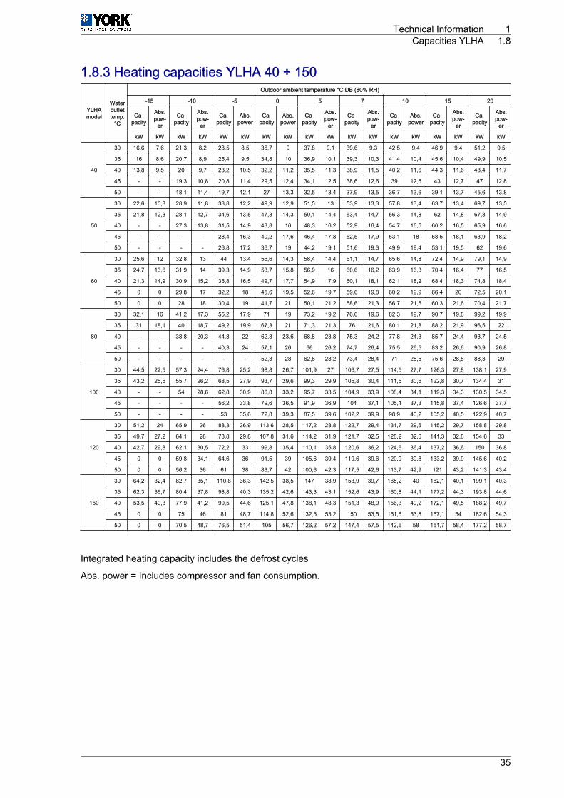
1.8.3 Heating capacities YLHA 40 ÷ 150
YLHAmodel
Wateroutlettemp.
°C
Outdoor ambient temperature °C DB (80% RH)
-15 -10 -5 0 5 7 10 15 20
Ca‐pacity
Abs.pow‐
er
Ca‐pacity
Abs.pow‐
er
Ca‐pacity
Abs.power
Ca‐pacity
Abs.power
Ca‐pacity
Abs.pow‐
er
Ca‐pacity
Abs.pow‐
er
Ca‐pacity
Abs.power
Ca‐pacity
Abs.pow‐
er
Ca‐pacity
Abs.pow‐
er
kW kW kW kW kW kW kW kW kW kW kW kW kW kW kW kW kW kW
40
30 16,6 7,6 21,3 8,2 28,5 8,5 36,7 9 37,8 9,1 39,6 9,3 42,5 9,4 46,9 9,4 51,2 9,5
35 16 8,6 20,7 8,9 25,4 9,5 34,8 10 36,9 10,1 39,3 10,3 41,4 10,4 45,6 10,4 49,9 10,5
40 13,8 9,5 20 9,7 23,2 10,5 32,2 11,2 35,5 11,3 38,9 11,5 40,2 11,6 44,3 11,6 48,4 11,7
45 - - 19,3 10,8 20,8 11,4 29,5 12,4 34,1 12,5 38,6 12,6 39 12,6 43 12,7 47 12,8
50 - - 18,1 11,4 19,7 12,1 27 13,3 32,5 13,4 37,9 13,5 36,7 13,6 39,1 13,7 45,6 13,8
50
30 22,6 10,8 28,9 11,8 38,8 12,2 49,9 12,9 51,5 13 53,9 13,3 57,8 13,4 63,7 13,4 69,7 13,5
35 21,8 12,3 28,1 12,7 34,6 13,5 47,3 14,3 50,1 14,4 53,4 14,7 56,3 14,8 62 14,8 67,8 14,9
40 - - 27,3 13,8 31,5 14,9 43,8 16 48,3 16,2 52,9 16,4 54,7 16,5 60,2 16,5 65,9 16,6
45 - - - - 28,4 16,3 40,2 17,6 46,4 17,8 52,5 17,9 53,1 18 58,5 18,1 63,9 18,2
50 - - - - 26,8 17,2 36,7 19 44,2 19,1 51,6 19,3 49,9 19,4 53,1 19,5 62 19,6
60
30 25,6 12 32,8 13 44 13,4 56,6 14,3 58,4 14,4 61,1 14,7 65,6 14,8 72,4 14,9 79,1 14,9
35 24,7 13,6 31,9 14 39,3 14,9 53,7 15,8 56,9 16 60,6 16,2 63,9 16,3 70,4 16,4 77 16,5
40 21,3 14,9 30,9 15,2 35,8 16,5 49,7 17,7 54,9 17,9 60,1 18,1 62,1 18,2 68,4 18,3 74,8 18,4
45 0 0 29,8 17 32,2 18 45,6 19,5 52,6 19,7 59,6 19,8 60,2 19,9 66,4 20 72,5 20,1
50 0 0 28 18 30,4 19 41,7 21 50,1 21,2 58,6 21,3 56,7 21,5 60,3 21,6 70,4 21,7
80
30 32,1 16 41,2 17,3 55,2 17,9 71 19 73,2 19,2 76,6 19,6 82,3 19,7 90,7 19,8 99,2 19,9
35 31 18,1 40 18,7 49,2 19,9 67,3 21 71,3 21,3 76 21,6 80,1 21,8 88,2 21,9 96,5 22
40 - - 38,8 20,3 44,8 22 62,3 23,6 68,8 23,8 75,3 24,2 77,8 24,3 85,7 24,4 93,7 24,5
45 - - - - 40,3 24 57,1 26 66 26,2 74,7 26,4 75,5 26,5 83,2 26,6 90,9 26,8
50 - - - - - - 52,3 28 62,8 28,2 73,4 28,4 71 28,6 75,6 28,8 88,3 29
100
30 44,5 22,5 57,3 24,4 76,8 25,2 98,8 26,7 101,9 27 106,7 27,5 114,5 27,7 126,3 27,8 138,1 27,9
35 43,2 25,5 55,7 26,2 68,5 27,9 93,7 29,6 99,3 29,9 105,8 30,4 111,5 30,6 122,8 30,7 134,4 31
40 - - 54 28,6 62,8 30,9 86,8 33,2 95,7 33,5 104,9 33,9 108,4 34,1 119,3 34,3 130,5 34,5
45 - - - - 56,2 33,8 79,6 36,5 91,9 36,9 104 37,1 105,1 37,3 115,8 37,4 126,6 37,7
50 - - - - 53 35,6 72,8 39,3 87,5 39,6 102,2 39,9 98,9 40,2 105,2 40,5 122,9 40,7
120
30 51,2 24 65,9 26 88,3 26,9 113,6 28,5 117,2 28,8 122,7 29,4 131,7 29,6 145,2 29,7 158,8 29,8
35 49,7 27,2 64,1 28 78,8 29,8 107,8 31,6 114,2 31,9 121,7 32,5 128,2 32,6 141,3 32,8 154,6 33
40 42,7 29,8 62,1 30,5 72,2 33 99,8 35,4 110,1 35,8 120,6 36,2 124,6 36,4 137,2 36,6 150 36,8
45 0 0 59,8 34,1 64,6 36 91,5 39 105,6 39,4 119,6 39,6 120,9 39,8 133,2 39,9 145,6 40,2
50 0 0 56,2 36 61 38 83,7 42 100,6 42,3 117,5 42,6 113,7 42,9 121 43,2 141,3 43,4
150
30 64,2 32,4 82,7 35,1 110,8 36,3 142,5 38,5 147 38,9 153,9 39,7 165,2 40 182,1 40,1 199,1 40,3
35 62,3 36,7 80,4 37,8 98,8 40,3 135,2 42,6 143,3 43,1 152,6 43,9 160,8 44,1 177,2 44,3 193,8 44,6
40 53,5 40,3 77,9 41,2 90,5 44,6 125,1 47,8 138,1 48,3 151,3 48,9 156,3 49,2 172,1 49,5 188,2 49,7
45 0 0 75 46 81 48,7 114,8 52,6 132,5 53,2 150 53,5 151,6 53,8 167,1 54 182,6 54,3
50 0 0 70,5 48,7 76,5 51,4 105 56,7 126,2 57,2 147,4 57,5 142,6 58 151,7 58,4 177,2 58,7
Integrated heating capacity includes the defrost cycles
Abs. power = Includes compressor and fan consumption.
Technical Information 1Capacities YLHA 1.8
35
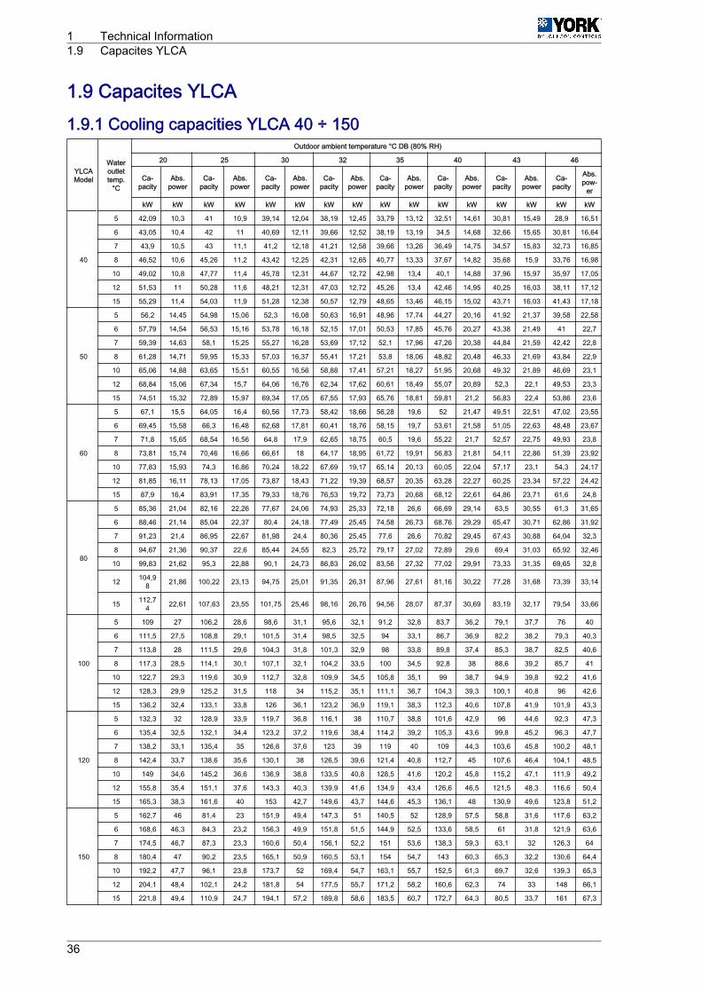
1.9 Capacites YLCA1.9.1 Cooling capacities YLCA 40 ÷ 150
YLCAModel
Wateroutlettemp.
°C
Outdoor ambient temperature °C DB (80% RH)
20 25 30 32 35 40 43 46
Ca‐pacity
Abs.power
Ca‐pacity
Abs.power
Ca‐pacity
Abs.power
Ca‐pacity
Abs.power
Ca‐pacity
Abs.power
Ca‐pacity
Abs.power
Ca‐pacity
Abs.power
Ca‐pacity
Abs.pow‐
er
kW kW kW kW kW kW kW kW kW kW kW kW kW kW kW kW
40
5 42,09 10,3 41 10,9 39,14 12,04 38,19 12,45 33,79 13,12 32,51 14,61 30,81 15,49 28,9 16,51
6 43,05 10,4 42 11 40,69 12,11 39,66 12,52 38,19 13,19 34,5 14,68 32,66 15,65 30,81 16,64
7 43,9 10,5 43 11,1 41,2 12,18 41,21 12,58 39,66 13,26 36,49 14,75 34,57 15,83 32,73 16,85
8 46,52 10,6 45,26 11,2 43,42 12,25 42,31 12,65 40,77 13,33 37,67 14,82 35,68 15,9 33,76 16,98
10 49,02 10,8 47,77 11,4 45,78 12,31 44,67 12,72 42,98 13,4 40,1 14,88 37,96 15,97 35,97 17,05
12 51,53 11 50,28 11,6 48,21 12,31 47,03 12,72 45,26 13,4 42,46 14,95 40,25 16,03 38,11 17,12
15 55,29 11,4 54,03 11,9 51,28 12,38 50,57 12,79 48,65 13,46 46,15 15,02 43,71 16,03 41,43 17,18
50
5 56,2 14,45 54,98 15,06 52,3 16,08 50,63 16,91 48,96 17,74 44,27 20,16 41,92 21,37 39,58 22,58
6 57,79 14,54 56,53 15,16 53,78 16,18 52,15 17,01 50,53 17,85 45,76 20,27 43,38 21,49 41 22,7
7 59,39 14,63 58,1 15,25 55,27 16,28 53,69 17,12 52,1 17,96 47,26 20,38 44,84 21,59 42,42 22,8
8 61,28 14,71 59,95 15,33 57,03 16,37 55,41 17,21 53,8 18,06 48,82 20,48 46,33 21,69 43,84 22,9
10 65,06 14,88 63,65 15,51 60,55 16,56 58,88 17,41 57,21 18,27 51,95 20,68 49,32 21,89 46,69 23,1
12 68,84 15,06 67,34 15,7 64,06 16,76 62,34 17,62 60,61 18,49 55,07 20,89 52,3 22,1 49,53 23,3
15 74,51 15,32 72,89 15,97 69,34 17,05 67,55 17,93 65,76 18,81 59,81 21,2 56,83 22,4 53,86 23,6
60
5 67,1 15,5 64,05 16,4 60,56 17,73 58,42 18,66 56,28 19,6 52 21,47 49,51 22,51 47,02 23,55
6 69,45 15,58 66,3 16,48 62,68 17,81 60,41 18,76 58,15 19,7 53,61 21,58 51,05 22,63 48,48 23,67
7 71,8 15,65 68,54 16,56 64,8 17,9 62,65 18,75 60,5 19,6 55,22 21,7 52,57 22,75 49,93 23,8
8 73,81 15,74 70,46 16,66 66,61 18 64,17 18,95 61,72 19,91 56,83 21,81 54,11 22,86 51,39 23,92
10 77,83 15,93 74,3 16,86 70,24 18,22 67,69 19,17 65,14 20,13 60,05 22,04 57,17 23,1 54,3 24,17
12 81,85 16,11 78,13 17,05 73,87 18,43 71,22 19,39 68,57 20,35 63,28 22,27 60,25 23,34 57,22 24,42
15 87,9 16,4 83,91 17,35 79,33 18,76 76,53 19,72 73,73 20,68 68,12 22,61 64,86 23,71 61,6 24,8
80
5 85,36 21,04 82,16 22,26 77,67 24,06 74,93 25,33 72,18 26,6 66,69 29,14 63,5 30,55 61,3 31,65
6 88,46 21,14 85,04 22,37 80,4 24,18 77,49 25,45 74,58 26,73 68,76 29,29 65,47 30,71 62,86 31,92
7 91,23 21,4 86,95 22,67 81,98 24,4 80,36 25,45 77,6 26,6 70,82 29,45 67,43 30,88 64,04 32,3
8 94,67 21,36 90,37 22,6 85,44 24,55 82,3 25,72 79,17 27,02 72,89 29,6 69,4 31,03 65,92 32,46
10 99,83 21,62 95,3 22,88 90,1 24,73 86,83 26,02 83,56 27,32 77,02 29,91 73,33 31,35 69,65 32,8
12 104,98 21,86 100,22 23,13 94,75 25,01 91,35 26,31 87,96 27,61 81,16 30,22 77,28 31,68 73,39 33,14
15 112,74 22,61 107,63 23,55 101,75 25,46 98,16 26,76 94,56 28,07 87,37 30,69 83,19 32,17 79,54 33,66
100
5 109 27 106,2 28,6 98,6 31,1 95,6 32,1 91,2 32,8 83,7 36,2 79,1 37,7 76 40
6 111,5 27,5 108,8 29,1 101,5 31,4 98,5 32,5 94 33,1 86,7 36,9 82,2 38,2 79,3 40,3
7 113,8 28 111,5 29,6 104,3 31,8 101,3 32,9 98 33,8 89,8 37,4 85,3 38,7 82,5 40,6
8 117,3 28,5 114,1 30,1 107,1 32,1 104,2 33,5 100 34,5 92,8 38 88,6 39,2 85,7 41
10 122,7 29,3 119,6 30,9 112,7 32,8 109,9 34,5 105,8 35,1 99 38,7 94,9 39,8 92,2 41,6
12 128,3 29,9 125,2 31,5 118 34 115,2 35,1 111,1 36,7 104,3 39,3 100,1 40,8 96 42,6
15 136,2 32,4 133,1 33,8 126 36,1 123,2 36,9 119,1 38,3 112,3 40,6 107,8 41,9 101,9 43,3
120
5 132,3 32 128,9 33,9 119,7 36,8 116,1 38 110,7 38,8 101,6 42,9 96 44,6 92,3 47,3
6 135,4 32,5 132,1 34,4 123,2 37,2 119,6 38,4 114,2 39,2 105,3 43,6 99,8 45,2 96,3 47,7
7 138,2 33,1 135,4 35 126,6 37,6 123 39 119 40 109 44,3 103,6 45,8 100,2 48,1
8 142,4 33,7 138,6 35,6 130,1 38 126,5 39,6 121,4 40,8 112,7 45 107,6 46,4 104,1 48,5
10 149 34,6 145,2 36,6 136,9 38,8 133,5 40,8 128,5 41,6 120,2 45,8 115,2 47,1 111,9 49,2
12 155,8 35,4 151,1 37,6 143,3 40,3 139,9 41,6 134,9 43,4 126,6 46,5 121,5 48,3 116,6 50,4
15 165,3 38,3 161,6 40 153 42,7 149,6 43,7 144,6 45,3 136,1 48 130,9 49,6 123,8 51,2
150
5 162,7 46 81,4 23 151,9 49,4 147,3 51 140,5 52 128,9 57,5 58,8 31,6 117,6 63,2
6 168,6 46,3 84,3 23,2 156,3 49,9 151,8 51,5 144,9 52,5 133,6 58,5 61 31,8 121,9 63,6
7 174,5 46,7 87,3 23,3 160,6 50,4 156,1 52,2 151 53,6 138,3 59,3 63,1 32 126,3 64
8 180,4 47 90,2 23,5 165,1 50,9 160,5 53,1 154 54,7 143 60,3 65,3 32,2 130,6 64,4
10 192,2 47,7 96,1 23,8 173,7 52 169,4 54,7 163,1 55,7 152,5 61,3 69,7 32,6 139,3 65,3
12 204,1 48,4 102,1 24,2 181,8 54 177,5 55,7 171,2 58,2 160,6 62,3 74 33 148 66,1
15 221,8 49,4 110,9 24,7 194,1 57,2 189,8 58,6 183,5 60,7 172,7 64,3 80,5 33,7 161 67,3
1 Technical Information1.9 Capacites YLCA
36
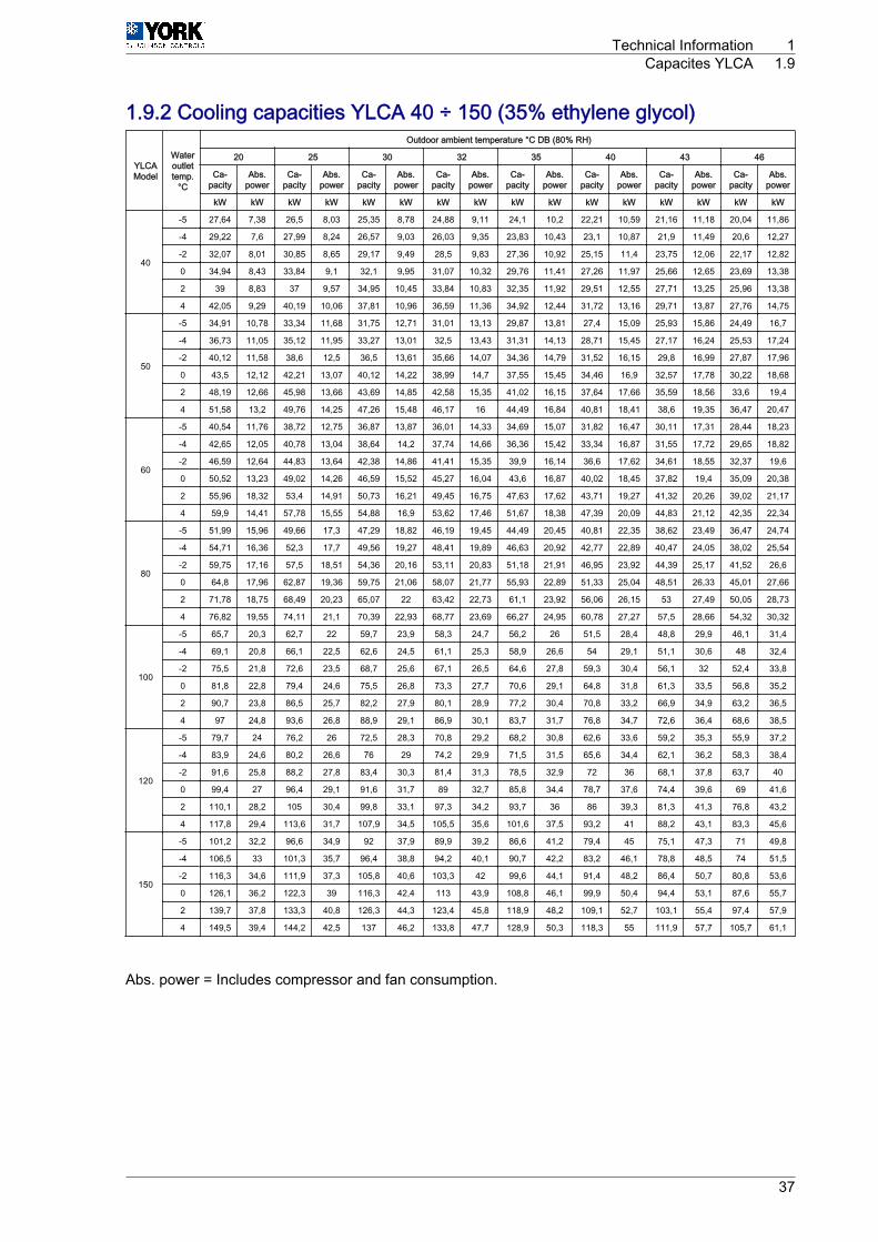
1.9.2 Cooling capacities YLCA 40 ÷ 150 (35% ethylene glycol)
YLCAModel
Wateroutlettemp.
°C
Outdoor ambient temperature °C DB (80% RH)
20 25 30 32 35 40 43 46
Ca‐pacity
Abs.power
Ca‐pacity
Abs.power
Ca‐pacity
Abs.power
Ca‐pacity
Abs.power
Ca‐pacity
Abs.power
Ca‐pacity
Abs.power
Ca‐pacity
Abs.power
Ca‐pacity
Abs.power
kW kW kW kW kW kW kW kW kW kW kW kW kW kW kW kW
40
-5 27,64 7,38 26,5 8,03 25,35 8,78 24,88 9,11 24,1 10,2 22,21 10,59 21,16 11,18 20,04 11,86
-4 29,22 7,6 27,99 8,24 26,57 9,03 26,03 9,35 23,83 10,43 23,1 10,87 21,9 11,49 20,6 12,27
-2 32,07 8,01 30,85 8,65 29,17 9,49 28,5 9,83 27,36 10,92 25,15 11,4 23,75 12,06 22,17 12,82
0 34,94 8,43 33,84 9,1 32,1 9,95 31,07 10,32 29,76 11,41 27,26 11,97 25,66 12,65 23,69 13,38
2 39 8,83 37 9,57 34,95 10,45 33,84 10,83 32,35 11,92 29,51 12,55 27,71 13,25 25,96 13,38
4 42,05 9,29 40,19 10,06 37,81 10,96 36,59 11,36 34,92 12,44 31,72 13,16 29,71 13,87 27,76 14,75
50
-5 34,91 10,78 33,34 11,68 31,75 12,71 31,01 13,13 29,87 13,81 27,4 15,09 25,93 15,86 24,49 16,7
-4 36,73 11,05 35,12 11,95 33,27 13,01 32,5 13,43 31,31 14,13 28,71 15,45 27,17 16,24 25,53 17,24
-2 40,12 11,58 38,6 12,5 36,5 13,61 35,66 14,07 34,36 14,79 31,52 16,15 29,8 16,99 27,87 17,96
0 43,5 12,12 42,21 13,07 40,12 14,22 38,99 14,7 37,55 15,45 34,46 16,9 32,57 17,78 30,22 18,68
2 48,19 12,66 45,98 13,66 43,69 14,85 42,58 15,35 41,02 16,15 37,64 17,66 35,59 18,56 33,6 19,4
4 51,58 13,2 49,76 14,25 47,26 15,48 46,17 16 44,49 16,84 40,81 18,41 38,6 19,35 36,47 20,47
60
-5 40,54 11,76 38,72 12,75 36,87 13,87 36,01 14,33 34,69 15,07 31,82 16,47 30,11 17,31 28,44 18,23
-4 42,65 12,05 40,78 13,04 38,64 14,2 37,74 14,66 36,36 15,42 33,34 16,87 31,55 17,72 29,65 18,82
-2 46,59 12,64 44,83 13,64 42,38 14,86 41,41 15,35 39,9 16,14 36,6 17,62 34,61 18,55 32,37 19,6
0 50,52 13,23 49,02 14,26 46,59 15,52 45,27 16,04 43,6 16,87 40,02 18,45 37,82 19,4 35,09 20,38
2 55,96 18,32 53,4 14,91 50,73 16,21 49,45 16,75 47,63 17,62 43,71 19,27 41,32 20,26 39,02 21,17
4 59,9 14,41 57,78 15,55 54,88 16,9 53,62 17,46 51,67 18,38 47,39 20,09 44,83 21,12 42,35 22,34
80
-5 51,99 15,96 49,66 17,3 47,29 18,82 46,19 19,45 44,49 20,45 40,81 22,35 38,62 23,49 36,47 24,74
-4 54,71 16,36 52,3 17,7 49,56 19,27 48,41 19,89 46,63 20,92 42,77 22,89 40,47 24,05 38,02 25,54
-2 59,75 17,16 57,5 18,51 54,36 20,16 53,11 20,83 51,18 21,91 46,95 23,92 44,39 25,17 41,52 26,6
0 64,8 17,96 62,87 19,36 59,75 21,06 58,07 21,77 55,93 22,89 51,33 25,04 48,51 26,33 45,01 27,66
2 71,78 18,75 68,49 20,23 65,07 22 63,42 22,73 61,1 23,92 56,06 26,15 53 27,49 50,05 28,73
4 76,82 19,55 74,11 21,1 70,39 22,93 68,77 23,69 66,27 24,95 60,78 27,27 57,5 28,66 54,32 30,32
100
-5 65,7 20,3 62,7 22 59,7 23,9 58,3 24,7 56,2 26 51,5 28,4 48,8 29,9 46,1 31,4
-4 69,1 20,8 66,1 22,5 62,6 24,5 61,1 25,3 58,9 26,6 54 29,1 51,1 30,6 48 32,4
-2 75,5 21,8 72,6 23,5 68,7 25,6 67,1 26,5 64,6 27,8 59,3 30,4 56,1 32 52,4 33,8
0 81,8 22,8 79,4 24,6 75,5 26,8 73,3 27,7 70,6 29,1 64,8 31,8 61,3 33,5 56,8 35,2
2 90,7 23,8 86,5 25,7 82,2 27,9 80,1 28,9 77,2 30,4 70,8 33,2 66,9 34,9 63,2 36,5
4 97 24,8 93,6 26,8 88,9 29,1 86,9 30,1 83,7 31,7 76,8 34,7 72,6 36,4 68,6 38,5
120
-5 79,7 24 76,2 26 72,5 28,3 70,8 29,2 68,2 30,8 62,6 33,6 59,2 35,3 55,9 37,2
-4 83,9 24,6 80,2 26,6 76 29 74,2 29,9 71,5 31,5 65,6 34,4 62,1 36,2 58,3 38,4
-2 91,6 25,8 88,2 27,8 83,4 30,3 81,4 31,3 78,5 32,9 72 36 68,1 37,8 63,7 40
0 99,4 27 96,4 29,1 91,6 31,7 89 32,7 85,8 34,4 78,7 37,6 74,4 39,6 69 41,6
2 110,1 28,2 105 30,4 99,8 33,1 97,3 34,2 93,7 36 86 39,3 81,3 41,3 76,8 43,2
4 117,8 29,4 113,6 31,7 107,9 34,5 105,5 35,6 101,6 37,5 93,2 41 88,2 43,1 83,3 45,6
150
-5 101,2 32,2 96,6 34,9 92 37,9 89,9 39,2 86,6 41,2 79,4 45 75,1 47,3 71 49,8
-4 106,5 33 101,3 35,7 96,4 38,8 94,2 40,1 90,7 42,2 83,2 46,1 78,8 48,5 74 51,5
-2 116,3 34,6 111,9 37,3 105,8 40,6 103,3 42 99,6 44,1 91,4 48,2 86,4 50,7 80,8 53,6
0 126,1 36,2 122,3 39 116,3 42,4 113 43,9 108,8 46,1 99,9 50,4 94,4 53,1 87,6 55,7
2 139,7 37,8 133,3 40,8 126,3 44,3 123,4 45,8 118,9 48,2 109,1 52,7 103,1 55,4 97,4 57,9
4 149,5 39,4 144,2 42,5 137 46,2 133,8 47,7 128,9 50,3 118,3 55 111,9 57,7 105,7 61,1
Abs. power = Includes compressor and fan consumption.
Technical Information 1Capacites YLCA 1.9
37
1.10 Cooling operation and hydraulic diagrams1.10.1 YLCA models: cooling only1 Heat exchange takes place between the heat transfer liquid (water or glycol water) and the refrigerant
in the plate heat exchanger.2 Water is cooled, and refrigerant is evaporated and reheated.3 Then the Scroll compressor condenses the refrigerant (gas) until the condensing pressure is reached,
and the refrigerant goes to the air cooled condensing unit.4 In the air cooled condensing unit, heat is exchanged between the air and the refrigerant.5 The air is heated and evacuated from the chiller (heat rejection).6 The refrigerant is condensed and sub-cooled.7 Then the refrigerant (liquid) goes on to the expansion element (expansion valve in YLCA 50 to 150
models) where it is expanded until the evaporating pressure is reached, at which time it goes to theplate heat exchanger to start a new cooling cycle.
1 Technical Information1.10 Cooling operation and hydraulic diagrams
38
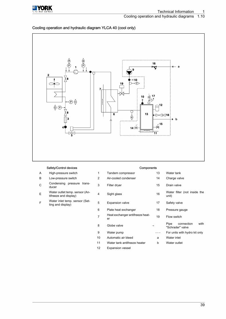
Cooling operation and hydraulic diagram YLCA 40 (cool only)
Safety/Control devices ComponentsA High-pressure switch 1 Tandem compressor 13 Water tankB Low-pressure switch 2 Air-cooled condenser 14 Charge valve
C Condensing pressure trans‐ducer 3 Filter dryer 15 Drain valve
E Water outlet temp. sensor (An‐tifreeze and display) 4 Sight glass 16 Water filter (not inside the
unit)
F Water inlet temp. sensor (Set‐ting and display) 5 Expansion valve 17 Safety valve
6 Plate heat exchanger 18 Pressure gauge
7 Heat exchanger antifreeze heat‐er 19 Flow switch
8 Globe valve → Pipe connection with"Schrader" valve
9 Water pump - ‑ ‑ For units with hydro kit only 10 Automatic air bleed a Water inlet 11 Water tank antifreeze heater b Water outlet 12 Expansion vessel
Technical Information 1Cooling operation and hydraulic diagrams 1.10
39
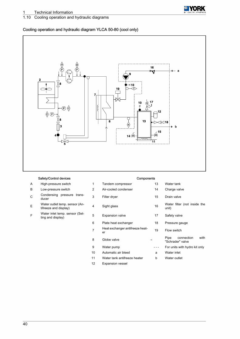
Cooling operation and hydraulic diagram YLCA 50-80 (cool only)
Safety/Control devices ComponentsA High-pressure switch 1 Tandem compressor 13 Water tankB Low-pressure switch 2 Air-cooled condenser 14 Charge valve
C Condensing pressure trans‐ducer 3 Filter dryer 15 Drain valve
E Water outlet temp. sensor (An‐tifreeze and display) 4 Sight glass 16 Water filter (not inside the
unit)
F Water inlet temp. sensor (Set‐ting and display) 5 Expansion valve 17 Safety valve
6 Plate heat exchanger 18 Pressure gauge
7 Heat exchanger antifreeze heat‐er 19 Flow switch
8 Globe valve → Pipe connection with"Schrader" valve
9 Water pump - ‑ ‑ For units with hydro kit only 10 Automatic air bleed a Water inlet 11 Water tank antifreeze heater b Water outlet 12 Expansion vessel
1 Technical Information1.10 Cooling operation and hydraulic diagrams
40
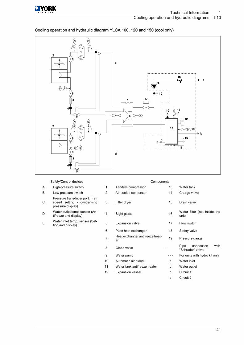
Cooling operation and hydraulic diagram YLCA 100, 120 and 150 (cool only)
Safety/Control devices ComponentsA High-pressure switch 1 Tandem compressor 13 Water tankB Low-pressure switch 2 Air-cooled condenser 14 Charge valve
CPressure transducer port. (Fanspeed setting ‑ condensingpressure display)
3 Filter dryer 15 Drain valve
D Water outlet temp. sensor (An‐tifreeze and display) 4 Sight glass 16 Water filter (not inside the
unit)
E Water inlet temp. sensor (Set‐ting and display) 5 Expansion valve 17 Flow switch
6 Plate heat exchanger 18 Safety valve
7 Heat exchanger antifreeze heat‐er 19 Pressure gauge
8 Globe valve → Pipe connection with"Schrader" valve
9 Water pump - ‑ ‑ For units with hydro kit only 10 Automatic air bleed a Water inlet 11 Water tank antifreeze heater b Water outlet 12 Expansion vessel c Circuit 1 d Circuit 2
Technical Information 1Cooling operation and hydraulic diagrams 1.10
41

1.10.2 YLHA models: heat pumpCooling cycle1 The 4-way valve is activated.2 Heat exchange takes place between the heat transfer liquid (water or glycol water) and the refrigerant
in the plate heat exchanger. Water is cooled, and refrigerant is evaporated and reheated.3 Then the Scroll-type compressor condenses the refrigerant (gas) until the condensing pressure is
reached, and the refrigerant goes to the air cooled condensing unit.4 In the air cooled condensing unit, heat is exchanged between the air and the refrigerant. The air is
heated and evacuated from the chiller (heat rejection).5 The refrigerant is condensed and sub-cooled.6 Then the refrigerant (liquid) goes on to the expansion element where it is expanded until the evapo‐
rating pressure is reached, at which time it goes to the plate heat exchanger to start a new coolingcycle.
Heating cycle
The cycle is reversed to heating mode. The 4-way valve is not activated. The condensing unit becomesthe evaporating unit and the evaporating unit becomes the condensing unit. The water in the plate heatexchanger is heated.
1 Technical Information1.10 Cooling operation and hydraulic diagrams
42
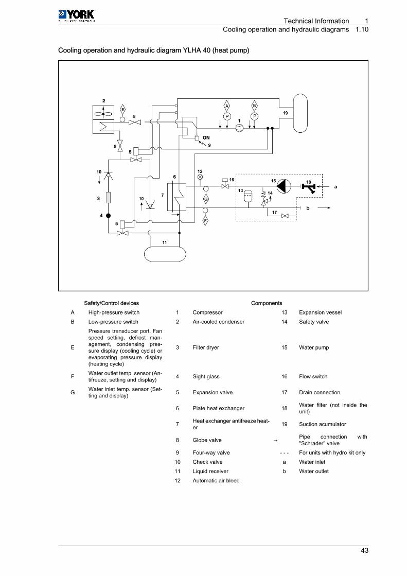
Cooling operation and hydraulic diagram YLHA 40 (heat pump)
Safety/Control devices ComponentsA High-pressure switch 1 Compressor 13 Expansion vesselB Low-pressure switch 2 Air-cooled condenser 14 Safety valve
E
Pressure transducer port. Fanspeed setting, defrost man‐agement, condensing pres‐sure display (cooling cycle) orevaporating pressure display(heating cycle)
3 Filter dryer 15 Water pump
F Water outlet temp. sensor (An‐tifreeze, setting and display) 4 Sight glass 16 Flow switch
G Water inlet temp. sensor (Set‐ting and display) 5 Expansion valve 17 Drain connection
6 Plate heat exchanger 18 Water filter (not inside theunit)
7 Heat exchanger antifreeze heat‐er 19 Suction acumulator
8 Globe valve → Pipe connection with"Schrader" valve
9 Four-way valve - ‑ ‑ For units with hydro kit only 10 Check valve a Water inlet 11 Liquid receiver b Water outlet 12 Automatic air bleed
Technical Information 1Cooling operation and hydraulic diagrams 1.10
43
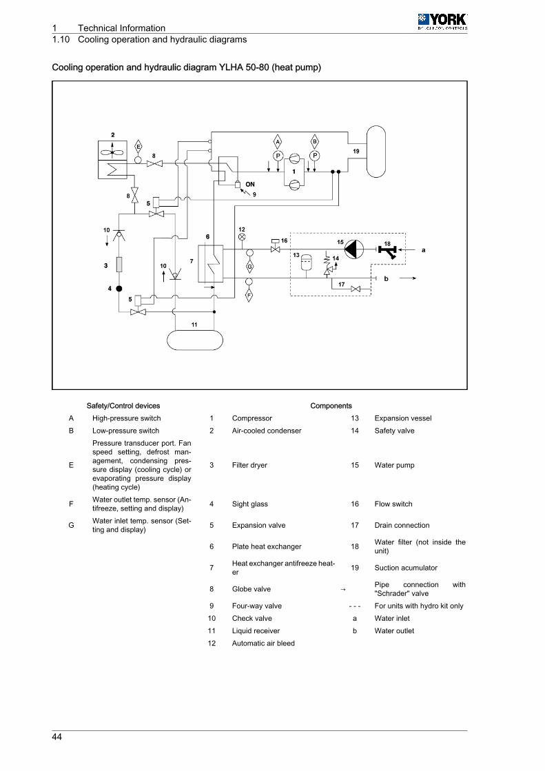
Cooling operation and hydraulic diagram YLHA 50-80 (heat pump)
Safety/Control devices ComponentsA High-pressure switch 1 Compressor 13 Expansion vesselB Low-pressure switch 2 Air-cooled condenser 14 Safety valve
E
Pressure transducer port. Fanspeed setting, defrost man‐agement, condensing pres‐sure display (cooling cycle) orevaporating pressure display(heating cycle)
3 Filter dryer 15 Water pump
F Water outlet temp. sensor (An‐tifreeze, setting and display) 4 Sight glass 16 Flow switch
G Water inlet temp. sensor (Set‐ting and display) 5 Expansion valve 17 Drain connection
6 Plate heat exchanger 18 Water filter (not inside theunit)
7 Heat exchanger antifreeze heat‐er 19 Suction acumulator
8 Globe valve → Pipe connection with"Schrader" valve
9 Four-way valve - ‑ ‑ For units with hydro kit only 10 Check valve a Water inlet 11 Liquid receiver b Water outlet 12 Automatic air bleed
1 Technical Information1.10 Cooling operation and hydraulic diagrams
44
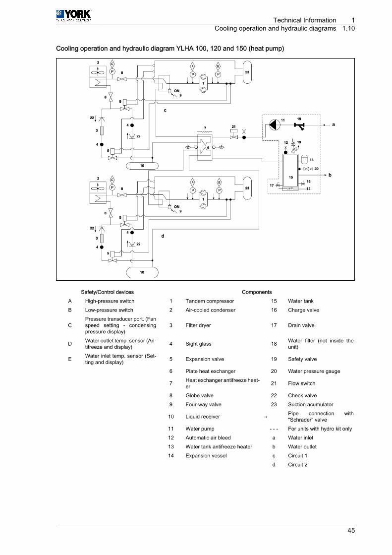
Cooling operation and hydraulic diagram YLHA 100, 120 and 150 (heat pump)
Safety/Control devices ComponentsA High-pressure switch 1 Tandem compressor 15 Water tankB Low-pressure switch 2 Air-cooled condenser 16 Charge valve
CPressure transducer port. (Fanspeed setting ‑ condensingpressure display)
3 Filter dryer 17 Drain valve
D Water outlet temp. sensor (An‐tifreeze and display) 4 Sight glass 18 Water filter (not inside the
unit)
E Water inlet temp. sensor (Set‐ting and display) 5 Expansion valve 19 Safety valve
6 Plate heat exchanger 20 Water pressure gauge
7 Heat exchanger antifreeze heat‐er 21 Flow switch
8 Globe valve 22 Check valve 9 Four-way valve 23 Suction acumulator
10 Liquid receiver → Pipe connection with"Schrader" valve
11 Water pump - ‑ ‑ For units with hydro kit only 12 Automatic air bleed a Water inlet 13 Water tank antifreeze heater b Water outlet 14 Expansion vessel c Circuit 1 d Circuit 2
Technical Information 1Cooling operation and hydraulic diagrams 1.10
45
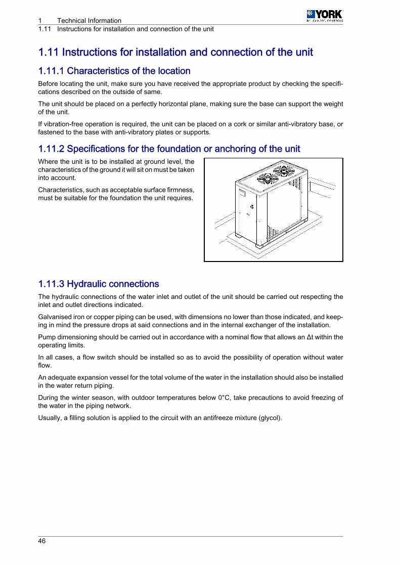
1.11 Instructions for installation and connection of the unit1.11.1 Characteristics of the locationBefore locating the unit, make sure you have received the appropriate product by checking the specifi‐cations described on the outside of same.
The unit should be placed on a perfectly horizontal plane, making sure the base can support the weightof the unit.
If vibration-free operation is required, the unit can be placed on a cork or similar anti-vibratory base, orfastened to the base with anti-vibratory plates or supports.
1.11.2 Specifications for the foundation or anchoring of the unitWhere the unit is to be installed at ground level, thecharacteristics of the ground it will sit on must be takeninto account.
Characteristics, such as acceptable surface firmness,must be suitable for the foundation the unit requires.
1.11.3 Hydraulic connectionsThe hydraulic connections of the water inlet and outlet of the unit should be carried out respecting theinlet and outlet directions indicated.
Galvanised iron or copper piping can be used, with dimensions no lower than those indicated, and keep‐ing in mind the pressure drops at said connections and in the internal exchanger of the installation.
Pump dimensioning should be carried out in accordance with a nominal flow that allows an Δt within theoperating limits.
In all cases, a flow switch should be installed so as to avoid the possibility of operation without waterflow.
An adequate expansion vessel for the total volume of the water in the installation should also be installedin the water return piping.
During the winter season, with outdoor temperatures below 0°C, take precautions to avoid freezing ofthe water in the piping network.
Usually, a filling solution is applied to the circuit with an antifreeze mixture (glycol).
1 Technical Information1.11 Instructions for installation and connection of the unit
46
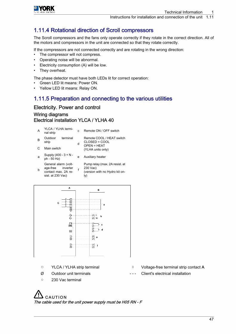
1.11.4 Rotational direction of Scroll compressorsThe Scroll compressors and the fans only operate correctly if they rotate in the correct direction. All ofthe motors and compressors in the unit are connected so that they rotate correctly.
If the compressors are not connected correctly and are rotating in the wrong direction:• The compressor will not compress.• Operating noise will be abnormal.• Electricity consumption (A) will be low.• They overheat.
The phase detector must have both LEDs lit for correct operation:• Green LED lit means: Power ON.• Yellow LED lit means: Relay ON.
1.11.5 Preparation and connecting to the various utilitiesElectricity. Power and controlWiring diagramsElectrical installation YLCA / YLHA 40
A YLCA / YLHA termi‐nal strip c Remote ON / OFF switch
B Outdoor terminalstrip d
Remote COOL / HEAT switchCLOSED = COOLOPEN = HEAT(YLHA units only)C Main switch
a Supply (400 ‑ 3 + N ‑ph ‑ 50 Hz) e Auxiliary heater
b
General alarm (volt‐age-free invertercontact max. 2A re‐sist. at 230 Vac)
f
Pump relay (max. 2A resist. at230 Vac)(version with no Hydro kit on‐ly)
□ YLCA / YLHA strip terminal ◊ Voltage-free terminal strip contact AØ Outdoor unit terminals - ‑ ‑ Client's electrical installation○ 230 Vac terminal
C A U T I O NThe cable used for the unit power supply must be H05 RN ‑ F
Technical Information 1Instructions for installation and connection of the unit 1.11
47

Electrical installation, YLCA 50, 60 and 80
A YLCA terminal strip bGeneral alarm (voltage-freeinverter contact max. 2A re‐sist. at 230 Vac)
B Outdoor terminalstrip c Remote ON / OFF switch
C Main switch dPump heat protectorsAuxiliary contactsPump contacts
a Supply (400 ‑ 3 + N ‑ph ‑ 50 Hz) e
Pump relay (max. 2A resist. at230 Vac)(Hydro kit version only)
□ Strip terminals ◊ Voltage-free terminal strip contactØ Outdoor unit terminals - ‑ ‑ Client's electrical installation○ 230 Vac terminal
C A U T I O NThe cable used for the unit power supply must be H05 RN ‑ F
1 Technical Information1.11 Instructions for installation and connection of the unit
48
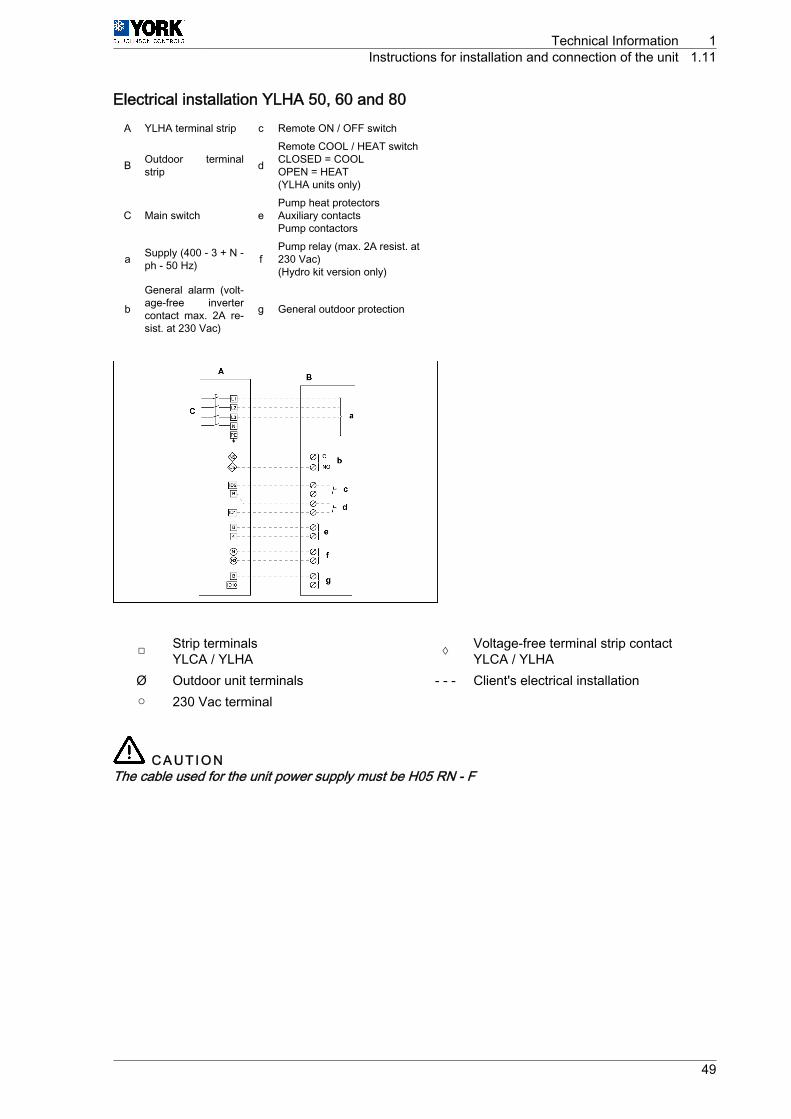
Electrical installation YLHA 50, 60 and 80A YLHA terminal strip c Remote ON / OFF switch
B Outdoor terminalstrip d
Remote COOL / HEAT switchCLOSED = COOLOPEN = HEAT(YLHA units only)
C Main switch ePump heat protectorsAuxiliary contactsPump contactors
a Supply (400 ‑ 3 + N ‑ph ‑ 50 Hz) f
Pump relay (max. 2A resist. at230 Vac)(Hydro kit version only)
b
General alarm (volt‐age-free invertercontact max. 2A re‐sist. at 230 Vac)
g General outdoor protection
□ Strip terminalsYLCA / YLHA ◊ Voltage-free terminal strip contact
YLCA / YLHAØ Outdoor unit terminals - ‑ ‑ Client's electrical installation○ 230 Vac terminal
C A U T I O NThe cable used for the unit power supply must be H05 RN ‑ F
Technical Information 1Instructions for installation and connection of the unit 1.11
49
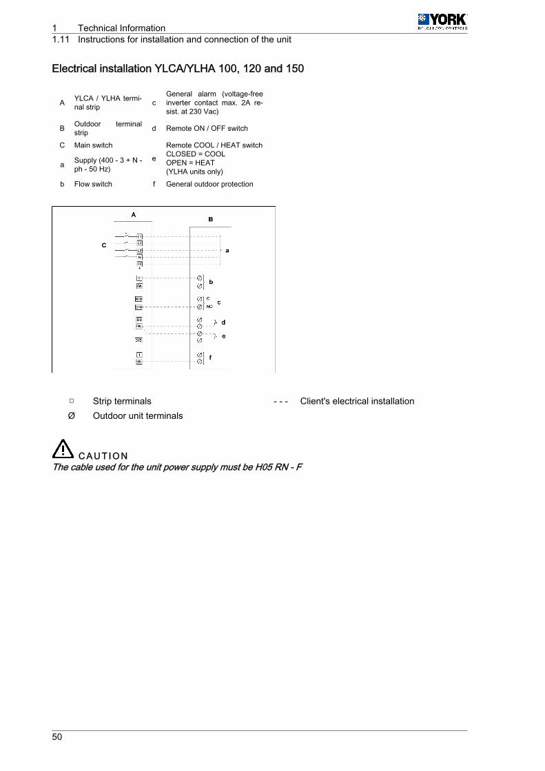
Electrical installation YLCA/YLHA 100, 120 and 150
A YLCA / YLHA termi‐nal strip c
General alarm (voltage-freeinverter contact max. 2A re‐sist. at 230 Vac)
B Outdoor terminalstrip d Remote ON / OFF switch
C Main switch
e
Remote COOL / HEAT switchCLOSED = COOLOPEN = HEAT(YLHA units only)
a Supply (400 ‑ 3 + N ‑ph ‑ 50 Hz)
b Flow switch f General outdoor protection
□ Strip terminals - ‑ ‑ Client's electrical installationØ Outdoor unit terminals
C A U T I O NThe cable used for the unit power supply must be H05 RN ‑ F
1 Technical Information1.11 Instructions for installation and connection of the unit
50
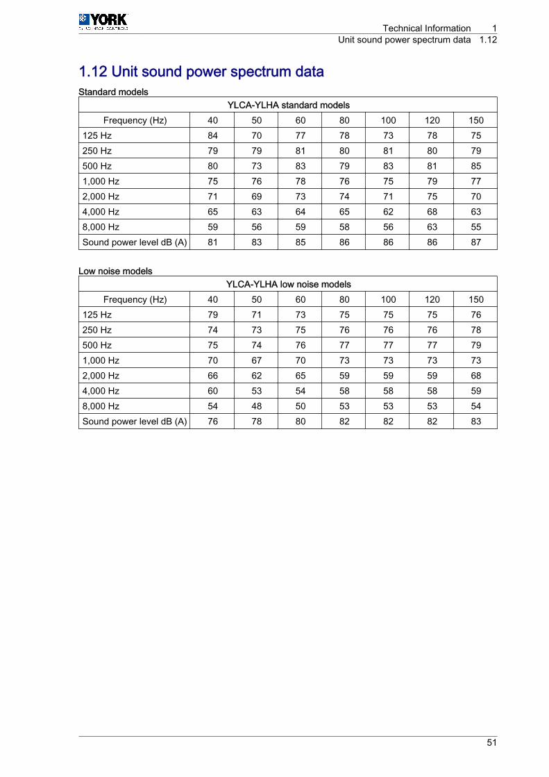
1.12 Unit sound power spectrum dataStandard models
YLCA-YLHA standard modelsFrequency (Hz) 40 50 60 80 100 120 150
125 Hz 84 70 77 78 73 78 75250 Hz 79 79 81 80 81 80 79500 Hz 80 73 83 79 83 81 851,000 Hz 75 76 78 76 75 79 772,000 Hz 71 69 73 74 71 75 704,000 Hz 65 63 64 65 62 68 638,000 Hz 59 56 59 58 56 63 55Sound power level dB (A) 81 83 85 86 86 86 87
Low noise modelsYLCA-YLHA low noise models
Frequency (Hz) 40 50 60 80 100 120 150125 Hz 79 71 73 75 75 75 76250 Hz 74 73 75 76 76 76 78500 Hz 75 74 76 77 77 77 791,000 Hz 70 67 70 73 73 73 732,000 Hz 66 62 65 59 59 59 684,000 Hz 60 53 54 58 58 58 598,000 Hz 54 48 50 53 53 53 54Sound power level dB (A) 76 78 80 82 82 82 83
Technical Information 1Unit sound power spectrum data 1.12
51
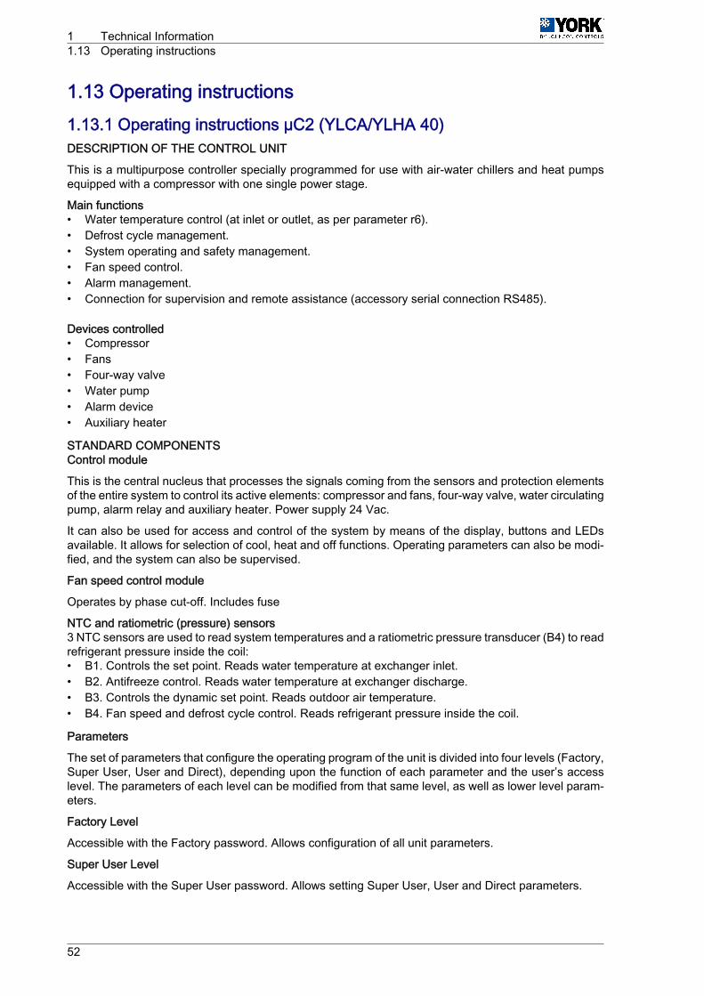
1.13 Operating instructions1.13.1 Operating instructions µC2 (YLCA/YLHA 40)DESCRIPTION OF THE CONTROL UNIT
This is a multipurpose controller specially programmed for use with air-water chillers and heat pumpsequipped with a compressor with one single power stage.
Main functions• Water temperature control (at inlet or outlet, as per parameter r6).• Defrost cycle management.• System operating and safety management.• Fan speed control.• Alarm management.• Connection for supervision and remote assistance (accessory serial connection RS485).
Devices controlled• Compressor• Fans• Four-way valve• Water pump• Alarm device• Auxiliary heater
STANDARD COMPONENTSControl module
This is the central nucleus that processes the signals coming from the sensors and protection elementsof the entire system to control its active elements: compressor and fans, four-way valve, water circulatingpump, alarm relay and auxiliary heater. Power supply 24 Vac.
It can also be used for access and control of the system by means of the display, buttons and LEDsavailable. It allows for selection of cool, heat and off functions. Operating parameters can also be modi‐fied, and the system can also be supervised.
Fan speed control module
Operates by phase cut-off. Includes fuse
NTC and ratiometric (pressure) sensors3 NTC sensors are used to read system temperatures and a ratiometric pressure transducer (B4) to readrefrigerant pressure inside the coil:• B1. Controls the set point. Reads water temperature at exchanger inlet.• B2. Antifreeze control. Reads water temperature at exchanger discharge.• B3. Controls the dynamic set point. Reads outdoor air temperature.• B4. Fan speed and defrost cycle control. Reads refrigerant pressure inside the coil.
Parameters
The set of parameters that configure the operating program of the unit is divided into four levels (Factory,Super User, User and Direct), depending upon the function of each parameter and the user’s accesslevel. The parameters of each level can be modified from that same level, as well as lower level param‐eters.
Factory Level
Accessible with the Factory password. Allows configuration of all unit parameters.
Super User Level
Accessible with the Super User password. Allows setting Super User, User and Direct parameters.
1 Technical Information1.13 Operating instructions
52
User Level
Accessible with password 22. Allows access to all parameters the user normally sets.
Direct Level
Accessible without a password. Allows for reading of the values detected by the sensors, as well as othersystem values. Can be used by the user without affecting unit operation.
General
Modification of the parameters that affect basic unit configuration should be made with the controller inStandby position.
Technical Information 1Operating instructions 1.13
53
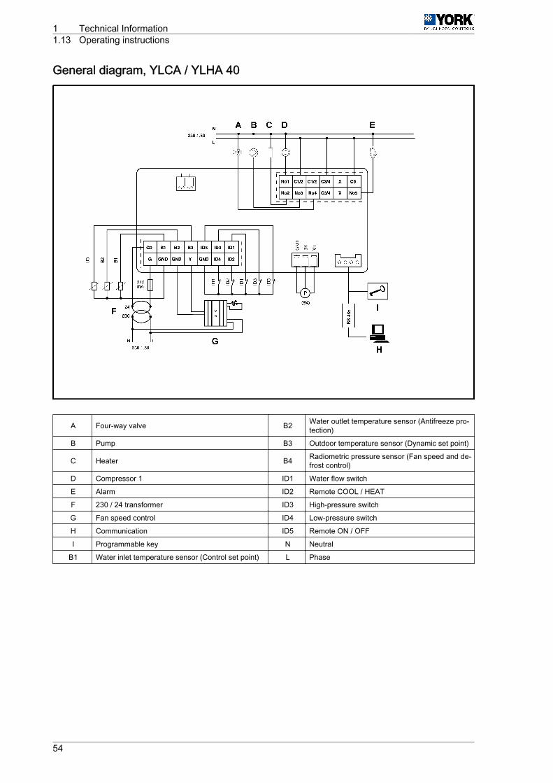
General diagram, YLCA / YLHA 40
A Four-way valve B2 Water outlet temperature sensor (Antifreeze pro‐tection)
B Pump B3 Outdoor temperature sensor (Dynamic set point)
C Heater B4 Radiometric pressure sensor (Fan speed and de‐frost control)
D Compressor 1 ID1 Water flow switch
E Alarm ID2 Remote COOL / HEAT
F 230 / 24 transformer ID3 High-pressure switch
G Fan speed control ID4 Low-pressure switch
H Communication ID5 Remote ON / OFF
I Programmable key N Neutral
B1 Water inlet temperature sensor (Control set point) L Phase
1 Technical Information1.13 Operating instructions
54

Symbols on the displayThe display has three figures in green, plus the signand one decimal. It also shows the symbols of thefunctions selected in orange (the alarm symbol is red).
Button ColourMeaning
LED permanently lit LED flashing
-2-
Orange
Compressor operating * Timing start-up
-7- Compressor on call -
-8- Water pump operating -
-9- Fans operating -
-10- Defrost active -
-12- Red Alarm activated -
-13-Orange
Cool cycle -
-1- Heat cycle -
(*) Operational compressor number
Button Unit status Pressing
-3-Loads default values Applies voltage when pressed
Returns to superior sub-group within programming area until output of same (ex‐cept changes in E2PROM) Press once
-6-Access to Direct parameters Press for 5 seconds
Selects a Direct parameter and shows its value / Confirms parameter changes Press once
-3- + ‑6- Parameter programming with password Press for 5 seconds
-4-
Selection of higher parameter within the programming area Press once or keep pressed down
Increase value Press once or keep pressed down
Selection of heat function from standby position and vice versa (P6=1) Press for 5 seconds
-5-
Selection of lower parameter within the programming area Press once or keep pressed down
Reduce value Press once or keep pressed down
Selection of cool function from standby position and vice versa (P6=1) Press for 5 seconds
-4- + ‑5-Manual alarm reset Press for 5 seconds
Clears hour counters (within programming area) Press for 5 seconds
-6- + ‑1- Forced manual defrost Press for 5 seconds
Technical Information 1Operating instructions 1.13
55
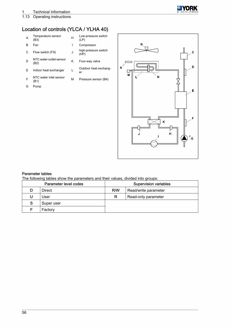
Location of controls (YLCA / YLHA 40)A Temperature sensor
(B3) H Low-pressure switch(LP)
B Fan I Compressor
C Flow switch (FS) J high-pressure switch(HP)
D NTC water outlet sensor(B2) K Four-way valve
E Indoor heat exchanger L Outdoor heat exchang‐er
F NTC water inlet sensor(B1) M Pressure sensor (B4)
G Pump
Parameter tablesThe following tables show the parameters and their values, divided into groups:
Parameter level codes Supervision variablesD Direct R/W Read/write parameterU User R Read-only parameterS Super user
F Factory
1 Technical Information1.13 Operating instructions
56
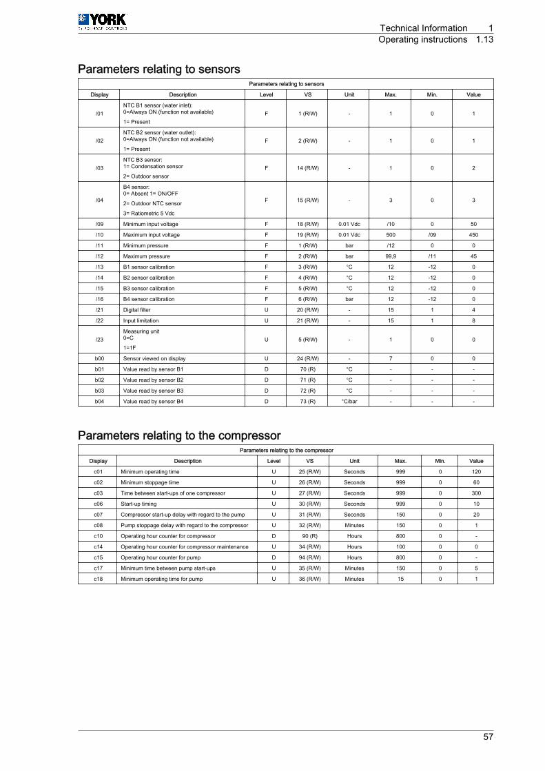
Parameters relating to sensorsParameters relating to sensors
Display Description Level VS Unit Max. Min. Value
/01NTC B1 sensor (water inlet):0=Always ON (function not available)
1= PresentF 1 (R/W) - 1 0 1
/02NTC B2 sensor (water outlet):0=Always ON (function not available)
1= PresentF 2 (R/W) - 1 0 1
/03NTC B3 sensor:1= Condensation sensor
2= Outdoor sensorF 14 (R/W) - 1 0 2
/04
B4 sensor:0= Absent 1= ON/OFF
2= Outdoor NTC sensor
3= Ratiometric 5 Vdc
F 15 (R/W) - 3 0 3
/09 Minimum input voltage F 18 (R/W) 0.01 Vdc /10 0 50
/10 Maximum input voltage F 19 (R/W) 0.01 Vdc 500 /09 450
/11 Minimum pressure F 1 (R/W) bar /12 0 0
/12 Maximum pressure F 2 (R/W) bar 99,9 /11 45
/13 B1 sensor calibration F 3 (R/W) °C 12 -12 0
/14 B2 sensor calibration F 4 (R/W) °C 12 -12 0
/15 B3 sensor calibration F 5 (R/W) °C 12 -12 0
/16 B4 sensor calibration F 6 (R/W) bar 12 -12 0
/21 Digital filter U 20 (R/W) - 15 1 4
/22 Input limitation U 21 (R/W) - 15 1 8
/23Measuring unit0=C
1=1FU 5 (R/W) - 1 0 0
b00 Sensor viewed on display U 24 (R/W) - 7 0 0
b01 Value read by sensor B1 D 70 (R) °C - - -
b02 Value read by sensor B2 D 71 (R) °C - - -
b03 Value read by sensor B3 D 72 (R) °C - - -
b04 Value read by sensor B4 D 73 (R) °C/bar - - -
Parameters relating to the compressorParameters relating to the compressor
Display Description Level VS Unit Max. Min. Value
c01 Minimum operating time U 25 (R/W) Seconds 999 0 120
c02 Minimum stoppage time U 26 (R/W) Seconds 999 0 60
c03 Time between start-ups of one compressor U 27 (R/W) Seconds 999 0 300
c06 Start-up timing U 30 (R/W) Seconds 999 0 10
c07 Compressor start-up delay with regard to the pump U 31 (R/W) Seconds 150 0 20
c08 Pump stoppage delay with regard to the compressor U 32 (R/W) Minutes 150 0 1
c10 Operating hour counter for compressor D 90 (R) Hours 800 0 -
c14 Operating hour counter for compressor maintenance U 34 (R/W) Hours 100 0 0
c15 Operating hour counter for pump D 94 (R/W) Hours 800 0 -
c17 Minimum time between pump start-ups U 35 (R/W) Minutes 150 0 5
c18 Minimum operating time for pump U 36 (R/W) Minutes 15 0 1
Technical Information 1Operating instructions 1.13
57

Operating graphicsMin. operating time of a compressor
A SignalB Compressor
Min. stoppage time of a compressorA SignalB Compressor
Min. time between compressor start-upsA SignalB Compressor
1 Technical Information1.13 Operating instructions
58
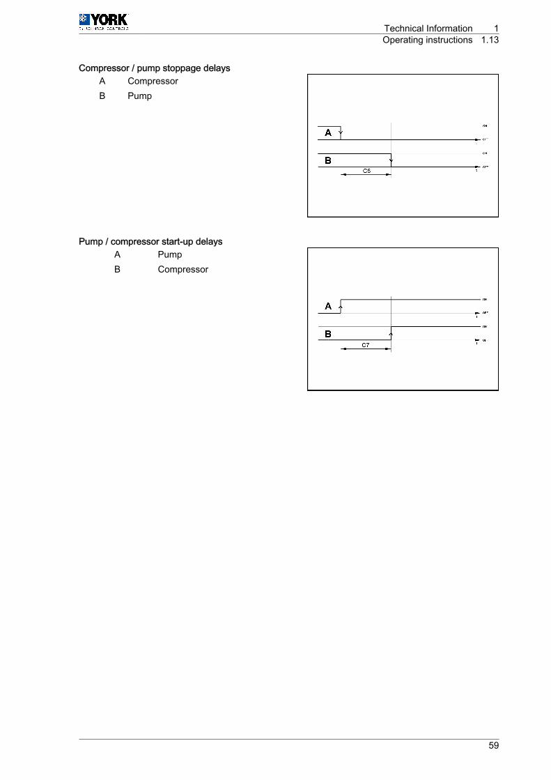
Compressor / pump stoppage delaysA CompressorB Pump
Pump / compressor start-up delaysA PumpB Compressor
Technical Information 1Operating instructions 1.13
59
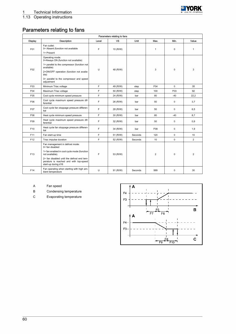
Parameters relating to fansParameters relating to fans
Display Description Level VS Unit Max. Min. Value
F01Fan outlet:0= Absent (function not available
1= PresentF 10 (R/W) 1 0 1
F02
Operating mode:0=Always ON (function not available)
1= parallel to the compressor (function notavailable)
2=ON/OFF operation (function not availa‐ble)
3= parallel to the compressor and speedadjustment
U 48 (R/W) 3 0 3
F03 Minimum Triac voltage F 49 (R/W) step F04 0 35
F04 Maximum Triac voltage F 50 (R/W) step 100 F03 92
F05 Cool cycle minimum speed pressure F 24 (R/W) bar 80 -40 22,2
F06 Cool cycle maximum speed pressure dif‐ferential F 26 (R/W) bar 50 0 3,7
F07 Cool cycle fan stoppage pressure differen‐tial F 28 (R/W) bar 50 0 6,5
F08 Heat cycle minimum speed pressure F 30 (R/W) bar 80 -40 8,7
F09 Heat cycle maximum speed pressure dif‐ferential F 32 (R/W) bar 50 0 0,9
F10 Heat cycle fan stoppage pressure differen‐tial F 34 (R/W) bar F08 0 1,9
F11 Fan start-up time F 51 (R/W) Seconds 120 0 10
F12 Triac impulse duration F 52 (R/W) Seconds 10 0 2
F13
Fan management in defrost mode:0= fan disabled
1= fan enabled in cool cycle mode (functionnot available).
2= fan disabled until the defrost end tem‐perature is reached and with top-speedstart-up during d16
F 53 (R/W) 2 0 2
F14 Fan operating when starting with high am‐bient temperature U 91 (R/W) Seconds 999 0 30
A Fan speedB Condensing temperatureC Evaporating temperature
1 Technical Information1.13 Operating instructions
60
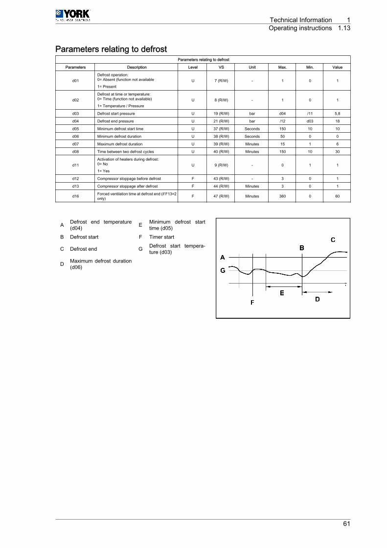
Parameters relating to defrostParameters relating to defrost
Parameters Description Level VS Unit Max. Min. Value
d01Defrost operation:0= Absent (function not available
1= PresentU 7 (R/W) - 1 0 1
d02Defrost at time or temperature:0= Time (function not available)
1= Temperature / PressureU 8 (R/W) - 1 0 1
d03 Defrost start pressure U 19 (R/W) bar d04 /11 5,8
d04 Defrost end pressure U 21 (R/W) bar /12 d03 18
d05 Minimum defrost start time U 37 (R/W) Seconds 150 10 10
d06 Minimum defrost duration U 38 (R/W) Seconds 50 0 0
d07 Maximum defrost duration U 39 (R/W) Minutes 15 1 6
d08 Time between two defrost cycles U 40 (R/W) Minutes 150 10 30
d11Activation of heaters during defrost:0= No
1= YesU 9 (R/W) - 0 1 1
d12 Compressor stoppage before defrost F 43 (R/W) - 3 0 1
d13 Compressor stoppage after defrost F 44 (R/W) Minutes 3 0 1
d16 Forced ventilation time at defrost end (if F13=2only) F 47 (R/W) Minutes 360 0 60
A Defrost end temperature(d04) E Minimum defrost start
time (d05)B Defrost start F Timer start
C Defrost end G Defrost start tempera‐ture (d03)
D Maximum defrost duration(d06)
Technical Information 1Operating instructions 1.13
61
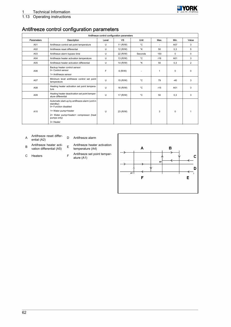
Antifreeze control configuration parametersAntifreeze control configuration parameters
Parameters Description Level VS Unit Max. Min. Value
A01 Antifreeze control set point temperature U 11 (R/W) °C - A07 3
A02 Antifreeze reset differential U 12 (R/W) °K 50 0,3 5
A03 Antifreeze alarm bypass time U 22 (R/W) Seconds 150 0 0
A04 Antifreeze heater activation temperature U 13 (R/W) °C r16 A01 3
A05 Antifreeze heater activation differential U 14 (R/W) °K 50 0,3 2
A06Backup heater control sensor:0= Control sensor
1= Antifreeze sensorF 6 (R/W) - 1 0 0
A07 Minimum level antifreeze control set pointtemperature U 15 (R/W) °C 79 -40 3
A08 Heating heater activation set point tempera‐ture U 16 (R/W) °C r15 A01 3
A09 Heating heater deactivation set point temper‐ature differential U 17 (R/W) °C 50 0,3 3
A10
Automatic start-up by antifreeze alarm (unit instandby):0= Function disabled
1= Water pump+heater
2= Water pump+heater+ compressor (heatpumps only)
3= Heater
U 23 (R/W) 3 0 1
A Antifreeze reset differ‐ential (A2) D Antifreeze alarm
B Antifreeze heater acti‐vation differential (A5) E Antifreeze heater activation
temperature (A4)
C Heaters F Antifreeze set point temper‐ature (A1)
1 Technical Information1.13 Operating instructions
62
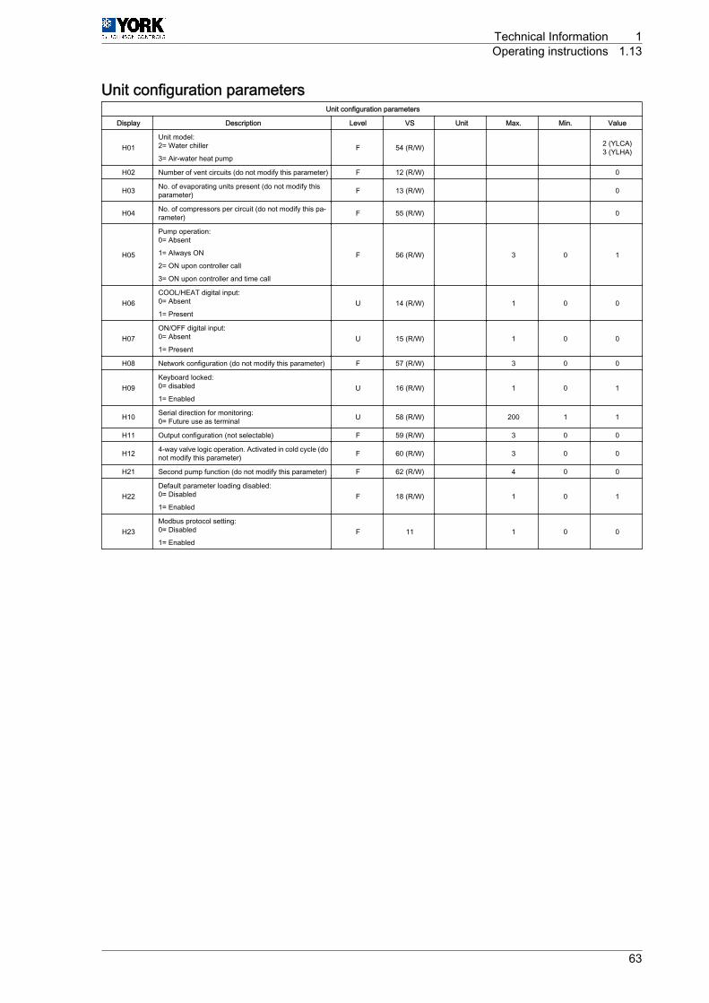
Unit configuration parametersUnit configuration parameters
Display Description Level VS Unit Max. Min. Value
H01Unit model:2= Water chiller
3= Air-water heat pumpF 54 (R/W) 2 (YLCA)
3 (YLHA)
H02 Number of vent circuits (do not modify this parameter) F 12 (R/W) 0
H03 No. of evaporating units present (do not modify thisparameter) F 13 (R/W) 0
H04 No. of compressors per circuit (do not modify this pa‐rameter) F 55 (R/W) 0
H05
Pump operation:0= Absent
1= Always ON
2= ON upon controller call
3= ON upon controller and time call
F 56 (R/W) 3 0 1
H06COOL/HEAT digital input:0= Absent
1= PresentU 14 (R/W) 1 0 0
H07ON/OFF digital input:0= Absent
1= PresentU 15 (R/W) 1 0 0
H08 Network configuration (do not modify this parameter) F 57 (R/W) 3 0 0
H09Keyboard locked:0= disabled
1= EnabledU 16 (R/W) 1 0 1
H10 Serial direction for monitoring:0= Future use as terminal U 58 (R/W) 200 1 1
H11 Output configuration (not selectable) F 59 (R/W) 3 0 0
H12 4-way valve logic operation. Activated in cold cycle (donot modify this parameter) F 60 (R/W) 3 0 0
H21 Second pump function (do not modify this parameter) F 62 (R/W) 4 0 0
H22Default parameter loading disabled:0= Disabled
1= EnabledF 18 (R/W) 1 0 1
H23Modbus protocol setting:0= Disabled
1= EnabledF 11 1 0 0
Technical Information 1Operating instructions 1.13
63
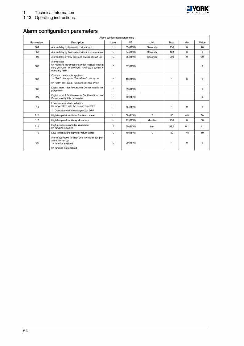
Alarm configuration parametersAlarm configuration parameters
Parameters Description Level VS Unit Max. Min. Value
P01 Alarm delay by flow switch at start-up. U 63 (R/W) Seconds 150 0 20
P02 Alarm delay by flow switch with unit in operation. U 64 (R/W) Seconds 120 0 5
P03 Alarm delay by low-pressure switch at start-up. U 65 (R/W) Seconds 200 0 60
P05
Alarm reset6= High and low-pressure switch manual reset atthird activation in one hour. Antifreeze control ismanually reset
F 67 (R/W) 6
P06Cool and heat cycle symbols.1= "Sun" heat cycle, "Snowflake" cool cycle
0= "Sun" cool cycle, "Snowflake" heat cycleF 19 (R/W) 1 0 1
P08 Digital input 1 for flow switch Do not modify thisparameter F 69 (R/W) 1
P09 Digital input 2 for the remote Cool/Heat function.Do not modify this parameter F 70 (R/W) 9
P15Low-pressure alarm selection.0= Inoperative with the compressor OFF
1= Operative with the compressor OFFF 76 (R/W) 1 0 1
P16 High-temperature alarm for return water U 38 (R/W) °C 80 -40 30
P17 High-temperature delay at start-up U 77 (R/W) Minutes 250 0 30
P18 High-pressure alarm by transducer0= function disabled F 39 (R/W) bar 99,9 0,1 41
P19 Low-temperature alarm for return water U 40 (R/W) °C 80 -40 10
P20
Alarm activation for high and low water temper‐ature at start-up.1= function enabled
0= function not enabled
U 20 (R/W) 1 0 0
1 Technical Information1.13 Operating instructions
64
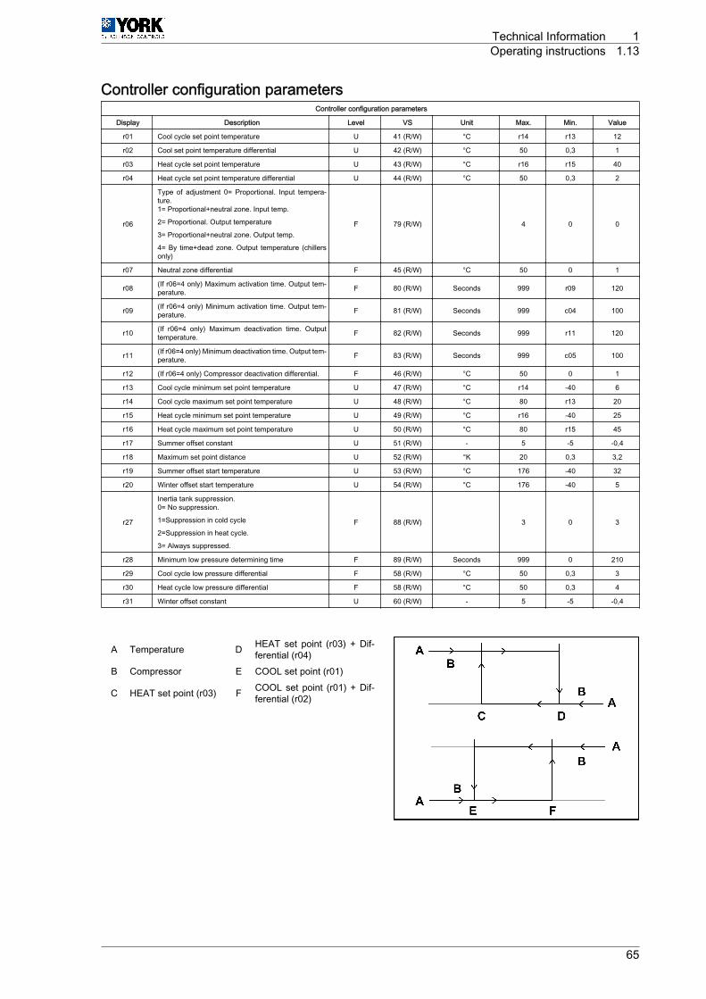
Controller configuration parametersController configuration parameters
Display Description Level VS Unit Max. Min. Value
r01 Cool cycle set point temperature U 41 (R/W) °C r14 r13 12
r02 Cool set point temperature differential U 42 (R/W) °C 50 0,3 1
r03 Heat cycle set point temperature U 43 (R/W) °C r16 r15 40
r04 Heat cycle set point temperature differential U 44 (R/W) °C 50 0,3 2
r06
Type of adjustment 0= Proportional. Input tempera‐ture.1= Proportional+neutral zone. Input temp.
2= Proportional. Output temperature
3= Proportional+neutral zone. Output temp.
4= By time+dead zone. Output temperature (chillersonly)
F 79 (R/W) 4 0 0
r07 Neutral zone differential F 45 (R/W) °C 50 0 1
r08 (If r06=4 only) Maximum activation time. Output tem‐perature. F 80 (R/W) Seconds 999 r09 120
r09 (If r06=4 only) Minimum activation time. Output tem‐perature. F 81 (R/W) Seconds 999 c04 100
r10 (If r06=4 only) Maximum deactivation time. Outputtemperature. F 82 (R/W) Seconds 999 r11 120
r11 (If r06=4 only) Minimum deactivation time. Output tem‐perature. F 83 (R/W) Seconds 999 c05 100
r12 (If r06=4 only) Compressor deactivation differential. F 46 (R/W) °C 50 0 1
r13 Cool cycle minimum set point temperature U 47 (R/W) °C r14 -40 6
r14 Cool cycle maximum set point temperature U 48 (R/W) °C 80 r13 20
r15 Heat cycle minimum set point temperature U 49 (R/W) °C r16 -40 25
r16 Heat cycle maximum set point temperature U 50 (R/W) °C 80 r15 45
r17 Summer offset constant U 51 (R/W) - 5 -5 -0,4
r18 Maximum set point distance U 52 (R/W) °K 20 0,3 3,2
r19 Summer offset start temperature U 53 (R/W) °C 176 -40 32
r20 Winter offset start temperature U 54 (R/W) °C 176 -40 5
r27
Inertia tank suppression.0= No suppression.
1=Suppression in cold cycle
2=Suppression in heat cycle.
3= Always suppressed.
F 88 (R/W) 3 0 3
r28 Minimum low pressure determining time F 89 (R/W) Seconds 999 0 210
r29 Cool cycle low pressure differential F 58 (R/W) °C 50 0,3 3
r30 Heat cycle low pressure differential F 58 (R/W) °C 50 0,3 4
r31 Winter offset constant U 60 (R/W) - 5 -5 -0,4
A Temperature D HEAT set point (r03) + Dif‐ferential (r04)
B Compressor E COOL set point (r01)
C HEAT set point (r03) F COOL set point (r01) + Dif‐ferential (r02)
Technical Information 1Operating instructions 1.13
65
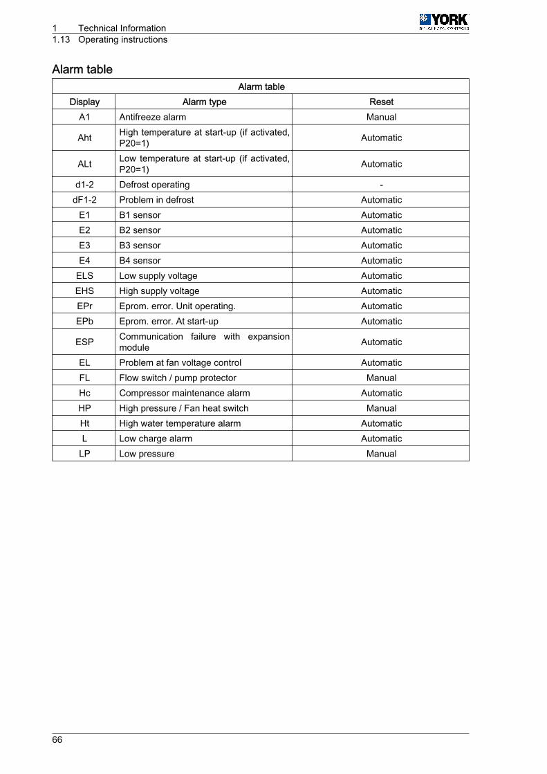
Alarm tableAlarm table
Display Alarm type ResetA1 Antifreeze alarm Manual
Aht High temperature at start-up (if activated,P20=1) Automatic
ALt Low temperature at start-up (if activated,P20=1) Automatic
d1-2 Defrost operating -dF1-2 Problem in defrost Automatic
E1 B1 sensor AutomaticE2 B2 sensor AutomaticE3 B3 sensor AutomaticE4 B4 sensor Automatic
ELS Low supply voltage AutomaticEHS High supply voltage AutomaticEPr Eprom. error. Unit operating. AutomaticEPb Eprom. error. At start-up Automatic
ESP Communication failure with expansionmodule Automatic
EL Problem at fan voltage control AutomaticFL Flow switch / pump protector ManualHc Compressor maintenance alarm AutomaticHP High pressure / Fan heat switch ManualHt High water temperature alarm AutomaticL Low charge alarm Automatic
LP Low pressure Manual
1 Technical Information1.13 Operating instructions
66
FunctionsAlarm reset
Pressing the UP and DOWN keys for 5 seconds cancels alarms present in the memory. At the sametime, the alarm message disappears from the display and the alarm relay is deactivated.
Forced defrost (heat pumps)
Pressing the SEL and UP keys simultaneously for 5 seconds activates forced defrost of the unit.
Clearing hour counters
While reading compressor or pump (c10 and c15) operating hours, said counters can be cleared bypressing the UP and DOWN keys simultaneously.
Pump operation
4 operating modes can be selected in accordance with the value given to parameter H5. H5=0 (pumpdisabled). H5=1 (pump permanently on), H5=2 (pump ON controlled by the regulator or in parallel withthe compressor), H5=3 (pump goes on and off at regular intervals, independent of compressor operation)(parameters c17 and c18).
Calibration of sensors
If necessary, sensors can be calibrated by using parameters /13, /14, /15 y /16. See Table Parametersrelating to sensors, see on page 57.
Remote ON/OFF
A remote ON/OFF inlet can be connected between terminals D5 and B on the connecting strip. To activatesaid inlet, a value of 1 should be given to parameter H07 (H07= 1). With this inlet open the unit is OFF;when closed, the unit is ON. This option does not disable the ON/OFF function of the keyboard.
Remote COOL/HEAT
A remote COOL/HEAT inlet can be connected between terminals D2 and B on the connecting strip. Toactivate said inlet, a value of 1 should be given to parameter H06 (H06= 1). With this inlet open the unitis in HEAT; when closed, the unit is in COOL. This function disables the COOL/HEAT function of thekeyboard.
Technical Information 1Operating instructions 1.13
67
1.13.2 Operating instructions µC2 (YLCA 50, 60 and 80)DESCRIPTION OF THE CONTROL UNIT
This is a multipurpose controller specially programmed for use with air-water chillers and heat pumpsequipped with a tandem compressor, two power stages and a single cooling circuit.
Main functions• Water temperature control (at inlet or outlet, as per parameter r6).• Defrost cycle management.• System operating and safety management.• Fan speed control.• Alarm management.• Connection for supervision and remote assistance (accessory serial connection RS485).
Devices controlled• Compressor• Fans• Four-way valve• Water pump• Alarm device• Heaters
STANDARD COMPONENTSBase control module for the system and the first compressor.
This is the central nucleus that processes the signals coming from the sensors and protection elementsof the entire system to control its active elements: compressors and fans, four-way valve, water circulatingpump, alarm relay and antifreeze heater. Power supply 24 Vac.
It can also be used for access and control of the system by means of the display, buttons and LEDsavailable. It allows for selection of cool, heat and off functions. Operating parameters can also be modi‐fied, and the system can also be supervised.
Fan speed control module
Operates by phase cut-off. Includes fuse
NTC and ratiometric (pressure) sensors3 NTC sensors are used to read system temperatures and a ratiometric pressure transducer (B4) to readrefrigerant pressure inside the coil:• B1. Controls the set point. Reads water temperature at exchanger inlet.• B2. Antifreeze control. Reads water temperature at exchanger discharge.• B3. Controls the dynamic set point. Reads outdoor air temperature.• B4. Fan speed and defrost cycle control. Reads refrigerant pressure inside the coil.
Parameters
The set of parameters that configure the operating program of the unit is divided into four levels (Factory,Super User, User and Direct), depending upon the function of each parameter and the user’s accesslevel. The parameters of each level can be modified from that same level, as well as lower level param‐eters.
Factory Level
Accessible with the Factory password. Allows configuration of all unit parameters.
Super User Level
Accessible with the Super User password. Allows setting Super User, User and Direct parameters.
User Level
Accessible with password 22. Allows access to all parameters the user normally sets.
1 Technical Information1.13 Operating instructions
68
Direct Level
Accessible without a password. Allows for reading of the values detected by the sensors, as well as othersystem values. Can be used by the user without affecting unit operation.
General
Modification of the parameters that affect basic unit configuration should be made with the controller inStandby position.
Technical Information 1Operating instructions 1.13
69

General diagram, YLCA 50, 60 and 80
A Compressor 2 B2 Water outlet temperature sensor (Antifreeze pro‐tection)
B Pump B3 Outdoor temperature sensor (Dynamic set point)
C Heater B4 Radiometric pressure sensor (Fan speed and de‐frost control)
D Compressor 1 ID1 Water flow switch
E Alarm ID2 Fan heat switches
F 230 / 24 transformer ID3 High-pressure switch
G Fan speed control ID4 Low-pressure switch
H Communication ID5 Remote ON / OFF
I Programmable key N Neutral
B1 Water inlet temperature sensor (Control set point) L Phase
1 Technical Information1.13 Operating instructions
70
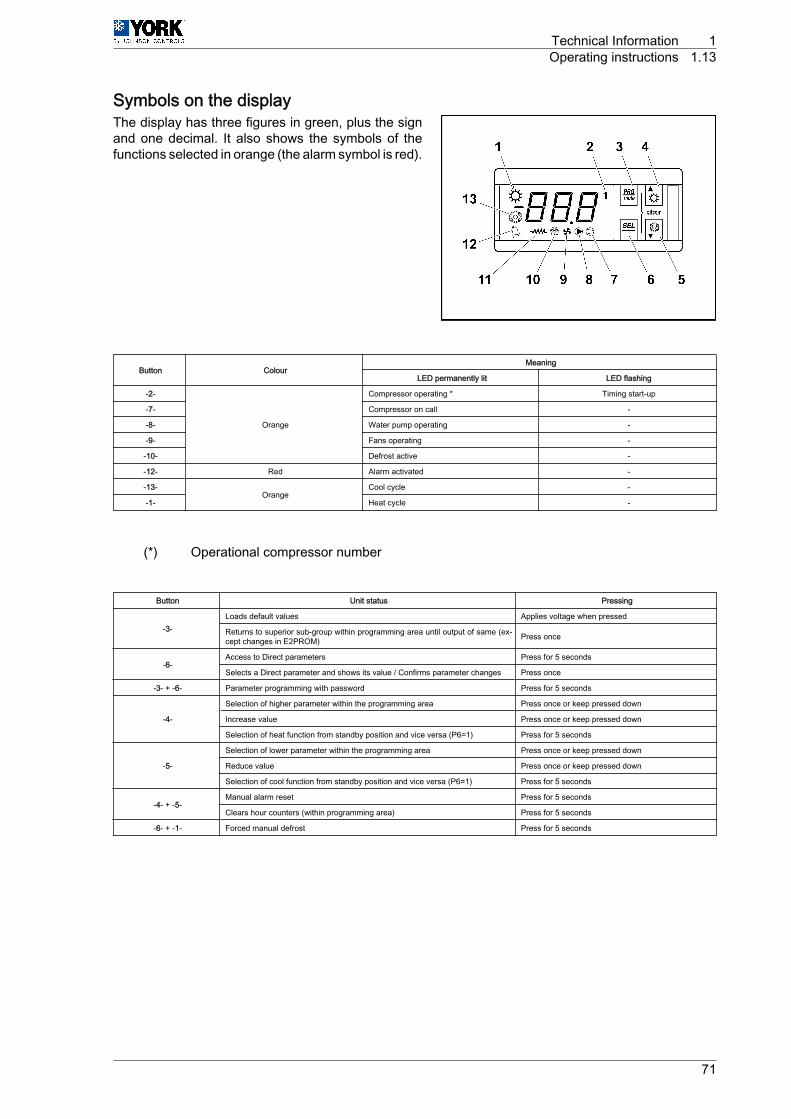
Symbols on the displayThe display has three figures in green, plus the signand one decimal. It also shows the symbols of thefunctions selected in orange (the alarm symbol is red).
Button ColourMeaning
LED permanently lit LED flashing
-2-
Orange
Compressor operating * Timing start-up
-7- Compressor on call -
-8- Water pump operating -
-9- Fans operating -
-10- Defrost active -
-12- Red Alarm activated -
-13-Orange
Cool cycle -
-1- Heat cycle -
(*) Operational compressor number
Button Unit status Pressing
-3-Loads default values Applies voltage when pressed
Returns to superior sub-group within programming area until output of same (ex‐cept changes in E2PROM) Press once
-6-Access to Direct parameters Press for 5 seconds
Selects a Direct parameter and shows its value / Confirms parameter changes Press once
-3- + ‑6- Parameter programming with password Press for 5 seconds
-4-
Selection of higher parameter within the programming area Press once or keep pressed down
Increase value Press once or keep pressed down
Selection of heat function from standby position and vice versa (P6=1) Press for 5 seconds
-5-
Selection of lower parameter within the programming area Press once or keep pressed down
Reduce value Press once or keep pressed down
Selection of cool function from standby position and vice versa (P6=1) Press for 5 seconds
-4- + ‑5-Manual alarm reset Press for 5 seconds
Clears hour counters (within programming area) Press for 5 seconds
-6- + ‑1- Forced manual defrost Press for 5 seconds
Technical Information 1Operating instructions 1.13
71
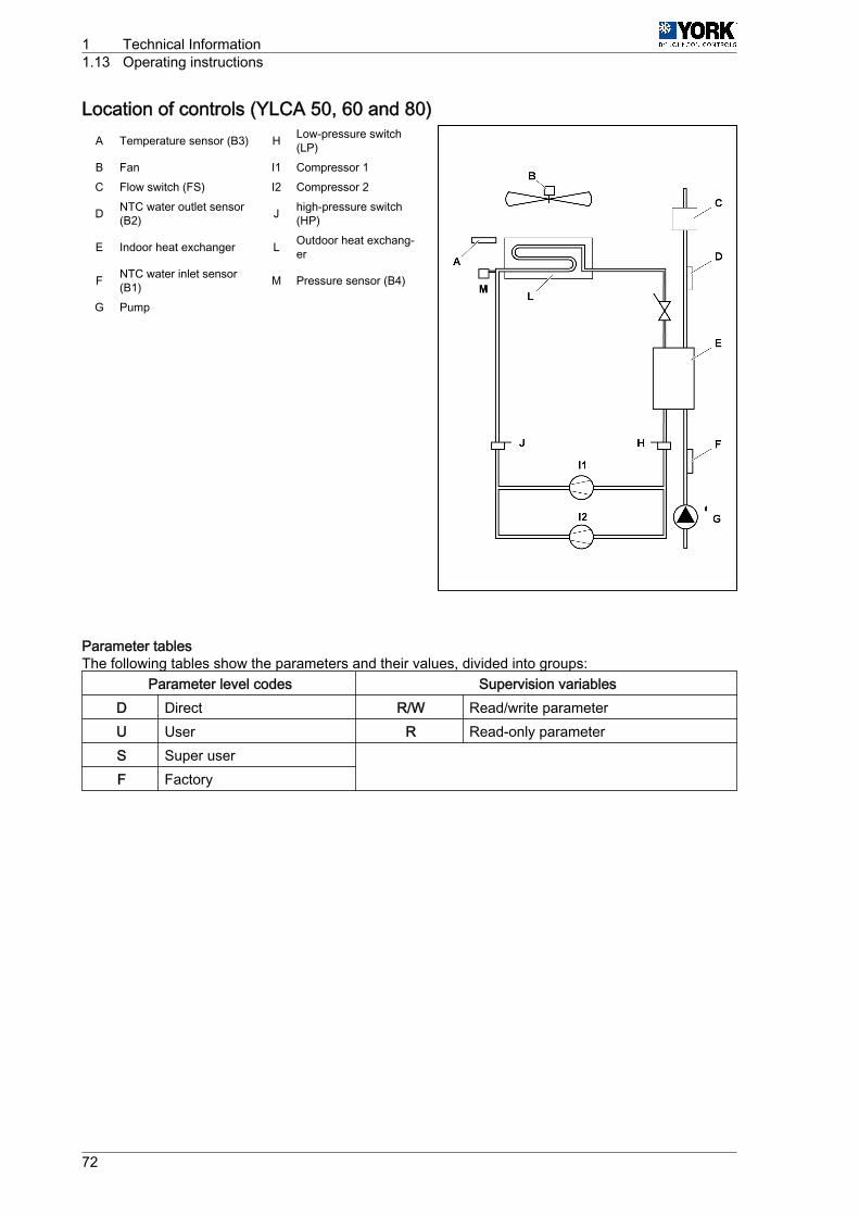
Location of controls (YLCA 50, 60 and 80)A Temperature sensor (B3) H Low-pressure switch
(LP)B Fan I1 Compressor 1C Flow switch (FS) I2 Compressor 2
D NTC water outlet sensor(B2) J high-pressure switch
(HP)
E Indoor heat exchanger L Outdoor heat exchang‐er
F NTC water inlet sensor(B1) M Pressure sensor (B4)
G Pump
Parameter tablesThe following tables show the parameters and their values, divided into groups:
Parameter level codes Supervision variablesD Direct R/W Read/write parameterU User R Read-only parameterS Super user
F Factory
1 Technical Information1.13 Operating instructions
72
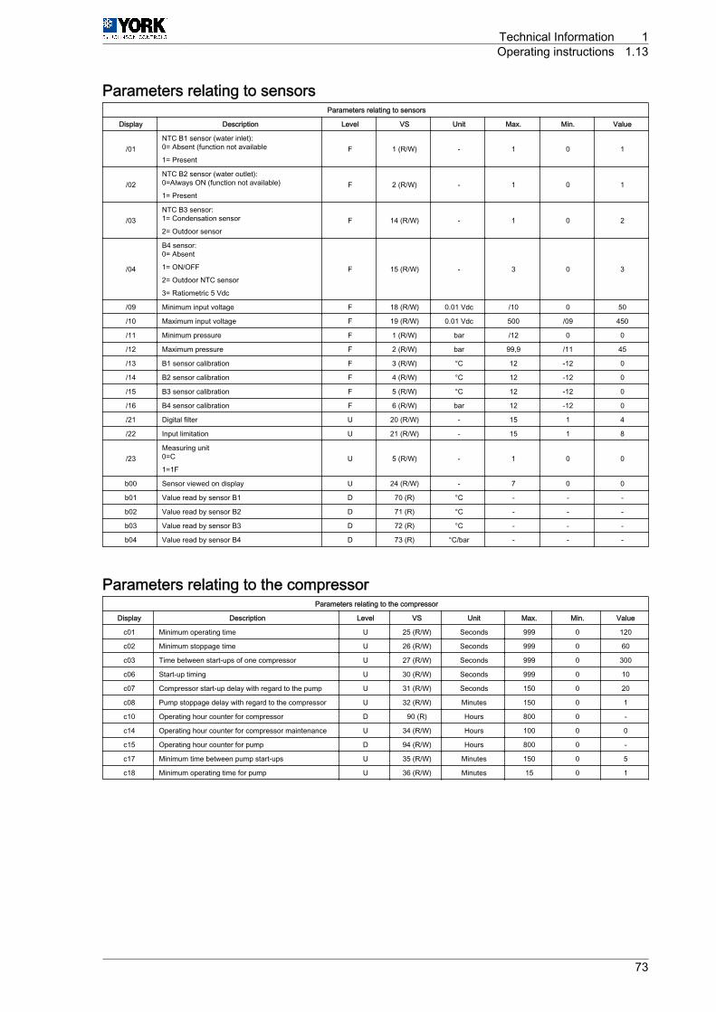
Parameters relating to sensorsParameters relating to sensors
Display Description Level VS Unit Max. Min. Value
/01NTC B1 sensor (water inlet):0= Absent (function not available
1= PresentF 1 (R/W) - 1 0 1
/02NTC B2 sensor (water outlet):0=Always ON (function not available)
1= PresentF 2 (R/W) - 1 0 1
/03NTC B3 sensor:1= Condensation sensor
2= Outdoor sensorF 14 (R/W) - 1 0 2
/04
B4 sensor:0= Absent
1= ON/OFF
2= Outdoor NTC sensor
3= Ratiometric 5 Vdc
F 15 (R/W) - 3 0 3
/09 Minimum input voltage F 18 (R/W) 0.01 Vdc /10 0 50
/10 Maximum input voltage F 19 (R/W) 0.01 Vdc 500 /09 450
/11 Minimum pressure F 1 (R/W) bar /12 0 0
/12 Maximum pressure F 2 (R/W) bar 99,9 /11 45
/13 B1 sensor calibration F 3 (R/W) °C 12 -12 0
/14 B2 sensor calibration F 4 (R/W) °C 12 -12 0
/15 B3 sensor calibration F 5 (R/W) °C 12 -12 0
/16 B4 sensor calibration F 6 (R/W) bar 12 -12 0
/21 Digital filter U 20 (R/W) - 15 1 4
/22 Input limitation U 21 (R/W) - 15 1 8
/23Measuring unit0=C
1=1FU 5 (R/W) - 1 0 0
b00 Sensor viewed on display U 24 (R/W) - 7 0 0
b01 Value read by sensor B1 D 70 (R) °C - - -
b02 Value read by sensor B2 D 71 (R) °C - - -
b03 Value read by sensor B3 D 72 (R) °C - - -
b04 Value read by sensor B4 D 73 (R) °C/bar - - -
Parameters relating to the compressorParameters relating to the compressor
Display Description Level VS Unit Max. Min. Value
c01 Minimum operating time U 25 (R/W) Seconds 999 0 120
c02 Minimum stoppage time U 26 (R/W) Seconds 999 0 60
c03 Time between start-ups of one compressor U 27 (R/W) Seconds 999 0 300
c06 Start-up timing U 30 (R/W) Seconds 999 0 10
c07 Compressor start-up delay with regard to the pump U 31 (R/W) Seconds 150 0 20
c08 Pump stoppage delay with regard to the compressor U 32 (R/W) Minutes 150 0 1
c10 Operating hour counter for compressor D 90 (R) Hours 800 0 -
c14 Operating hour counter for compressor maintenance U 34 (R/W) Hours 100 0 0
c15 Operating hour counter for pump D 94 (R/W) Hours 800 0 -
c17 Minimum time between pump start-ups U 35 (R/W) Minutes 150 0 5
c18 Minimum operating time for pump U 36 (R/W) Minutes 15 0 1
Technical Information 1Operating instructions 1.13
73
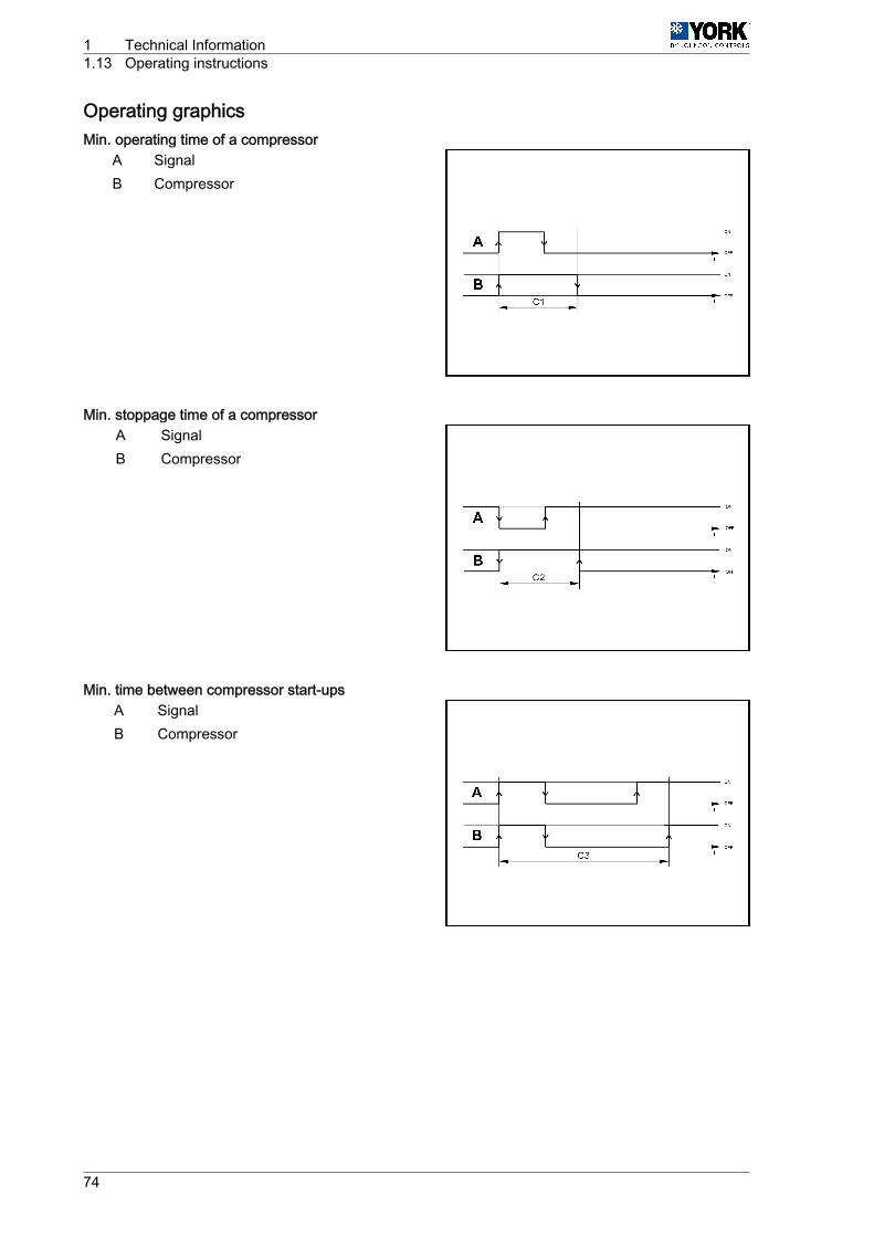
Operating graphicsMin. operating time of a compressor
A SignalB Compressor
Min. stoppage time of a compressorA SignalB Compressor
Min. time between compressor start-upsA SignalB Compressor
1 Technical Information1.13 Operating instructions
74
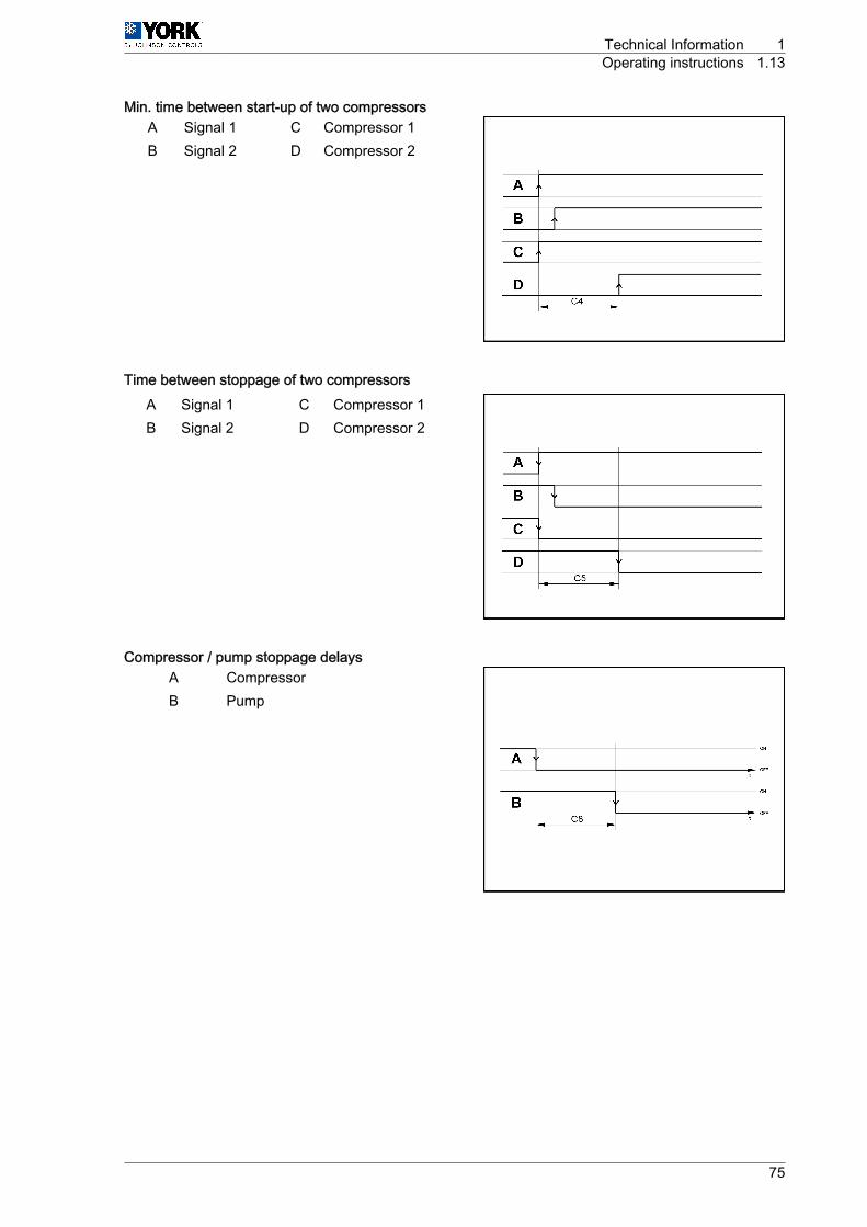
Min. time between start-up of two compressorsA Signal 1 C Compressor 1B Signal 2 D Compressor 2
Time between stoppage of two compressorsA Signal 1 C Compressor 1B Signal 2 D Compressor 2
Compressor / pump stoppage delaysA CompressorB Pump
Technical Information 1Operating instructions 1.13
75
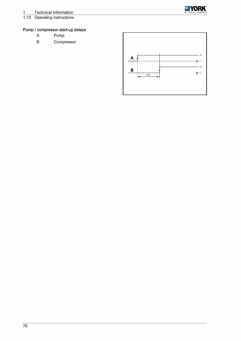
Pump / compressor start-up delaysA PumpB Compressor
1 Technical Information1.13 Operating instructions
76
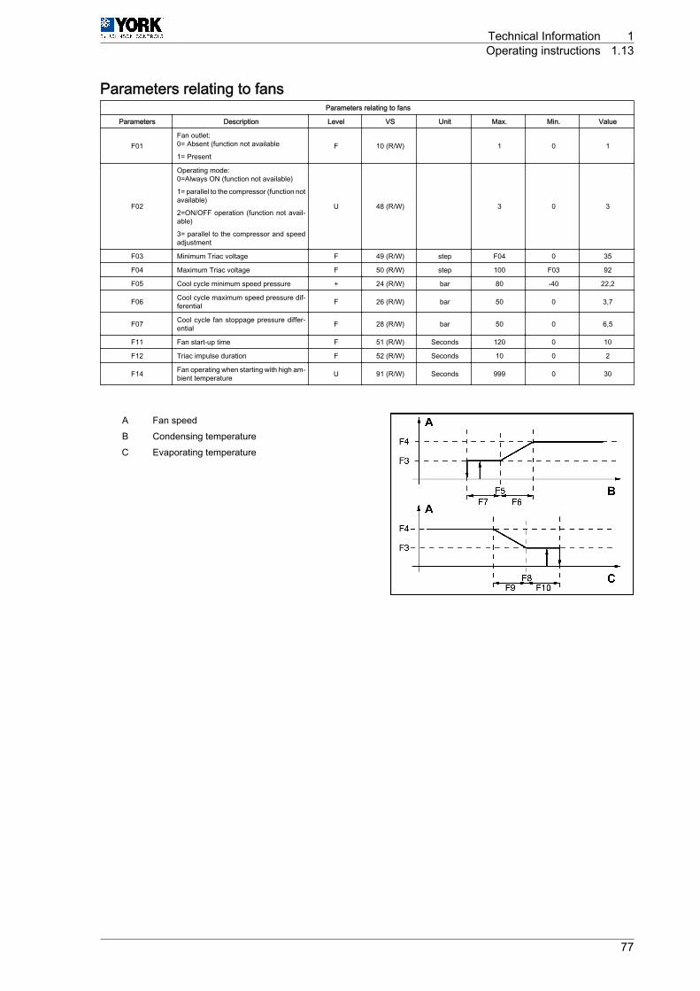
Parameters relating to fansParameters relating to fans
Parameters Description Level VS Unit Max. Min. Value
F01Fan outlet:0= Absent (function not available
1= PresentF 10 (R/W) 1 0 1
F02
Operating mode:0=Always ON (function not available)
1= parallel to the compressor (function notavailable)
2=ON/OFF operation (function not avail‐able)
3= parallel to the compressor and speedadjustment
U 48 (R/W) 3 0 3
F03 Minimum Triac voltage F 49 (R/W) step F04 0 35
F04 Maximum Triac voltage F 50 (R/W) step 100 F03 92
F05 Cool cycle minimum speed pressure + 24 (R/W) bar 80 -40 22,2
F06 Cool cycle maximum speed pressure dif‐ferential F 26 (R/W) bar 50 0 3,7
F07 Cool cycle fan stoppage pressure differ‐ential F 28 (R/W) bar 50 0 6,5
F11 Fan start-up time F 51 (R/W) Seconds 120 0 10
F12 Triac impulse duration F 52 (R/W) Seconds 10 0 2
F14 Fan operating when starting with high am‐bient temperature U 91 (R/W) Seconds 999 0 30
A Fan speedB Condensing temperatureC Evaporating temperature
Technical Information 1Operating instructions 1.13
77
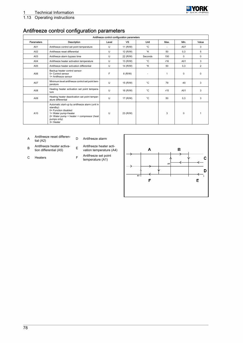
Antifreeze control configuration parametersAntifreeze control configuration parameters
Parameters Description Level VS Unit Max. Min. Value
A01 Antifreeze control set point temperature U 11 (R/W) °C - A07 3
A02 Antifreeze reset differential U 12 (R/W) °K 50 0,3 5
A03 Antifreeze alarm bypass time U 22 (R/W) Seconds 150 0 0
A04 Antifreeze heater activation temperature U 13 (R/W) °C r16 A01 3
A05 Antifreeze heater activation differential U 14 (R/W) °K 50 0,3 2
A06Backup heater control sensor:0= Control sensor1= Antifreeze sensor
F 6 (R/W) - 1 0 0
A07 Minimum level antifreeze control set point tem‐perature U 15 (R/W) °C 79 -40 3
A08 Heating heater activation set point tempera‐ture U 16 (R/W) °C r15 A01 3
A09 Heating heater deactivation set point temper‐ature differential U 17 (R/W) °C 50 0,3 3
A10
Automatic start-up by antifreeze alarm (unit instandby):0= Function disabled1= Water pump+heater2= Water pump + heater + compressor (heatpumps only)3= Heater
U 23 (R/W) 3 0 1
A Antifreeze reset differen‐tial (A2) D Antifreeze alarm
B Antifreeze heater activa‐tion differential (A5) E Antifreeze heater acti‐
vation temperature (A4)
C Heaters F Antifreeze set pointtemperature (A1)
1 Technical Information1.13 Operating instructions
78
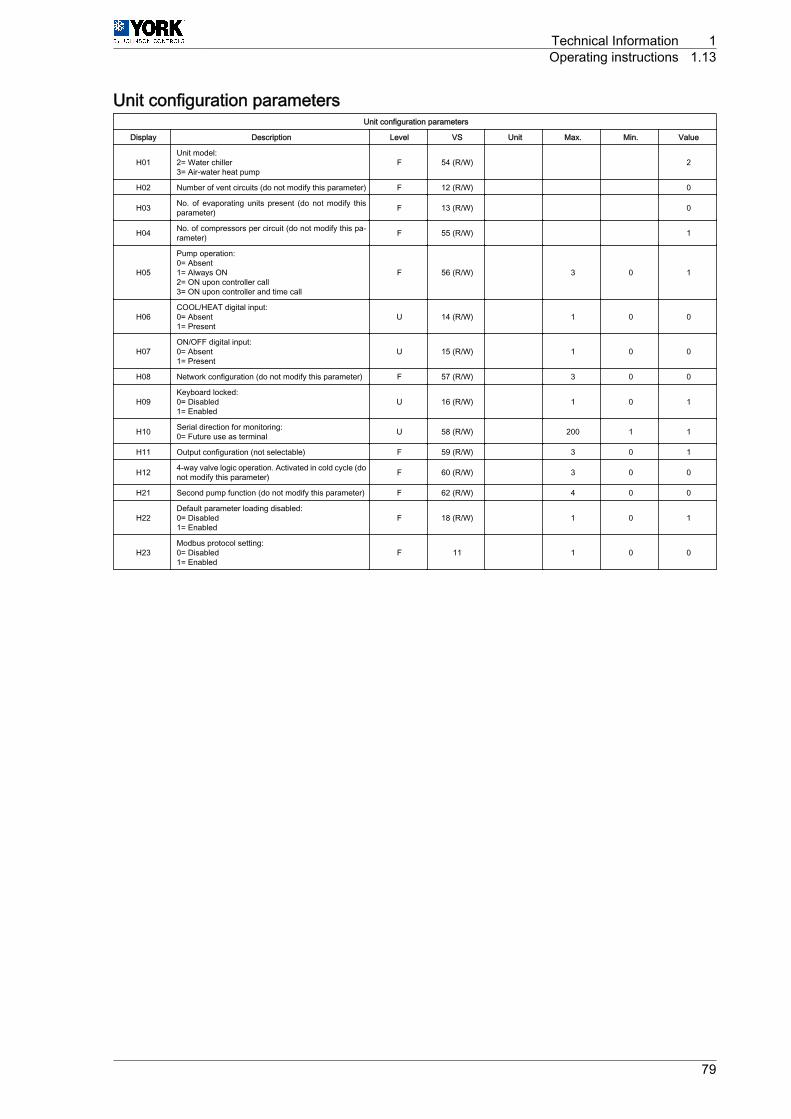
Unit configuration parametersUnit configuration parameters
Display Description Level VS Unit Max. Min. Value
H01Unit model:2= Water chiller3= Air-water heat pump
F 54 (R/W) 2
H02 Number of vent circuits (do not modify this parameter) F 12 (R/W) 0
H03 No. of evaporating units present (do not modify thisparameter) F 13 (R/W) 0
H04 No. of compressors per circuit (do not modify this pa‐rameter) F 55 (R/W) 1
H05
Pump operation:0= Absent1= Always ON2= ON upon controller call3= ON upon controller and time call
F 56 (R/W) 3 0 1
H06COOL/HEAT digital input:0= Absent1= Present
U 14 (R/W) 1 0 0
H07ON/OFF digital input:0= Absent1= Present
U 15 (R/W) 1 0 0
H08 Network configuration (do not modify this parameter) F 57 (R/W) 3 0 0
H09Keyboard locked:0= Disabled1= Enabled
U 16 (R/W) 1 0 1
H10 Serial direction for monitoring:0= Future use as terminal U 58 (R/W) 200 1 1
H11 Output configuration (not selectable) F 59 (R/W) 3 0 1
H12 4-way valve logic operation. Activated in cold cycle (donot modify this parameter) F 60 (R/W) 3 0 0
H21 Second pump function (do not modify this parameter) F 62 (R/W) 4 0 0
H22Default parameter loading disabled:0= Disabled1= Enabled
F 18 (R/W) 1 0 1
H23Modbus protocol setting:0= Disabled1= Enabled
F 11 1 0 0
Technical Information 1Operating instructions 1.13
79

Alarm configuration parametersAlarm configuration parameters
Parameters Description Level VS Unit Max. Min. Value
P01 Alarm delay by flow switch at start-up. U 63 (R/W) Seconds 150 0 20
P02 Alarm delay by flow switch with unit in operation. U 64 (R/W) Seconds 120 0 5
P03 Alarm delay by low-pressure switch at start-up. U 65 (R/W) Seconds 200 0 60
P05
Alarm reset6= High and low-pressure switch manual reset atthird activation in one hour. Antifreeze control ismanually reset
F 67 (R/W) 6
P06Cool and heat cycle symbols.1= "Sun" heat cycle, "Snowflake" cool cycle
0= "Sun" cool cycle, "Snowflake" heat cycleF 19 (R/W) 1 0 1
P08 Digital input 1 for flow switch Do not modify thisparameter F 69 (R/W) 1
P09 Digital input 2 for the remote Cool/Heat function.Do not modify this parameter F 70 (R/W) 9
P15Low-pressure alarm selection.0= Inoperative with the compressor OFF
1= Operative with the compressor OFFF 76 (R/W) 1 0 1
P16 High-temperature alarm for return water U 38 (R/W) °C 80 -40 30
P17 High-temperature delay at start-up U 77 (R/W) Minutes 250 0 30
P18 High-pressure alarm by transducer0= function disabled F 39 (R/W) bar 99,9 0,1 41
P19 Low-temperature alarm for return water U 40 (R/W) °C 80 -40 10
P20
Alarm activation for high and low water temper‐ature at start-up.1= function enabled
0= function not enabled
U 20 (R/W) 1 0 0
1 Technical Information1.13 Operating instructions
80
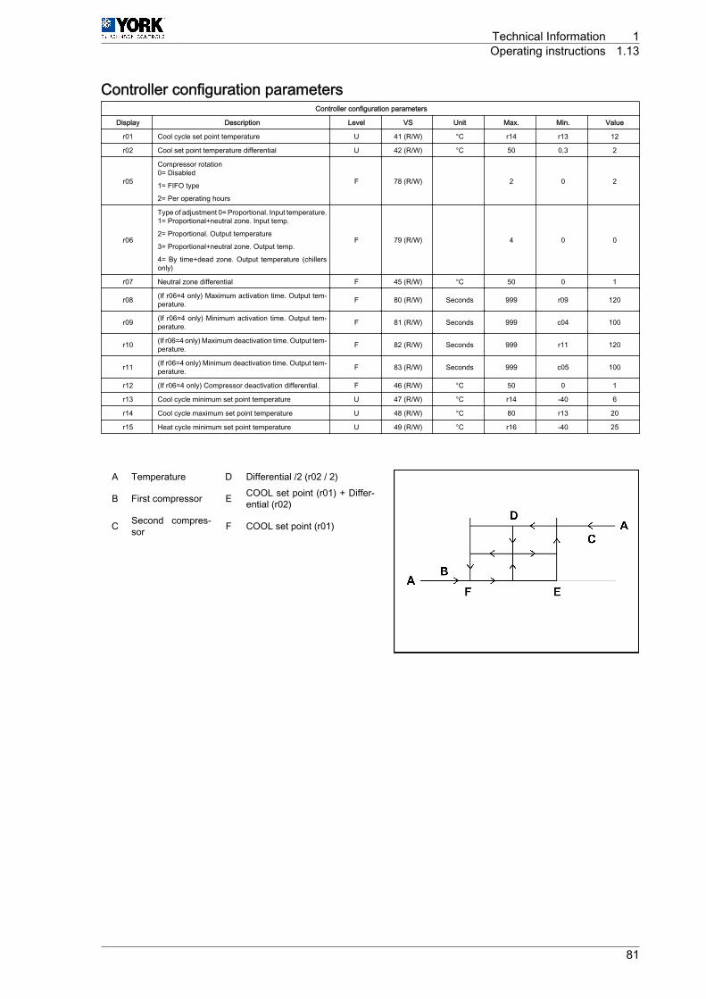
Controller configuration parametersController configuration parameters
Display Description Level VS Unit Max. Min. Value
r01 Cool cycle set point temperature U 41 (R/W) °C r14 r13 12
r02 Cool set point temperature differential U 42 (R/W) °C 50 0,3 2
r05
Compressor rotation0= Disabled
1= FIFO type
2= Per operating hours
F 78 (R/W) 2 0 2
r06
Type of adjustment 0= Proportional. Input temperature.1= Proportional+neutral zone. Input temp.
2= Proportional. Output temperature
3= Proportional+neutral zone. Output temp.
4= By time+dead zone. Output temperature (chillersonly)
F 79 (R/W) 4 0 0
r07 Neutral zone differential F 45 (R/W) °C 50 0 1
r08 (If r06=4 only) Maximum activation time. Output tem‐perature. F 80 (R/W) Seconds 999 r09 120
r09 (If r06=4 only) Minimum activation time. Output tem‐perature. F 81 (R/W) Seconds 999 c04 100
r10 (If r06=4 only) Maximum deactivation time. Output tem‐perature. F 82 (R/W) Seconds 999 r11 120
r11 (If r06=4 only) Minimum deactivation time. Output tem‐perature. F 83 (R/W) Seconds 999 c05 100
r12 (If r06=4 only) Compressor deactivation differential. F 46 (R/W) °C 50 0 1
r13 Cool cycle minimum set point temperature U 47 (R/W) °C r14 -40 6
r14 Cool cycle maximum set point temperature U 48 (R/W) °C 80 r13 20
r15 Heat cycle minimum set point temperature U 49 (R/W) °C r16 -40 25
A Temperature D Differential /2 (r02 / 2)
B First compressor E COOL set point (r01) + Differ‐ential (r02)
C Second compres‐sor F COOL set point (r01)
Technical Information 1Operating instructions 1.13
81
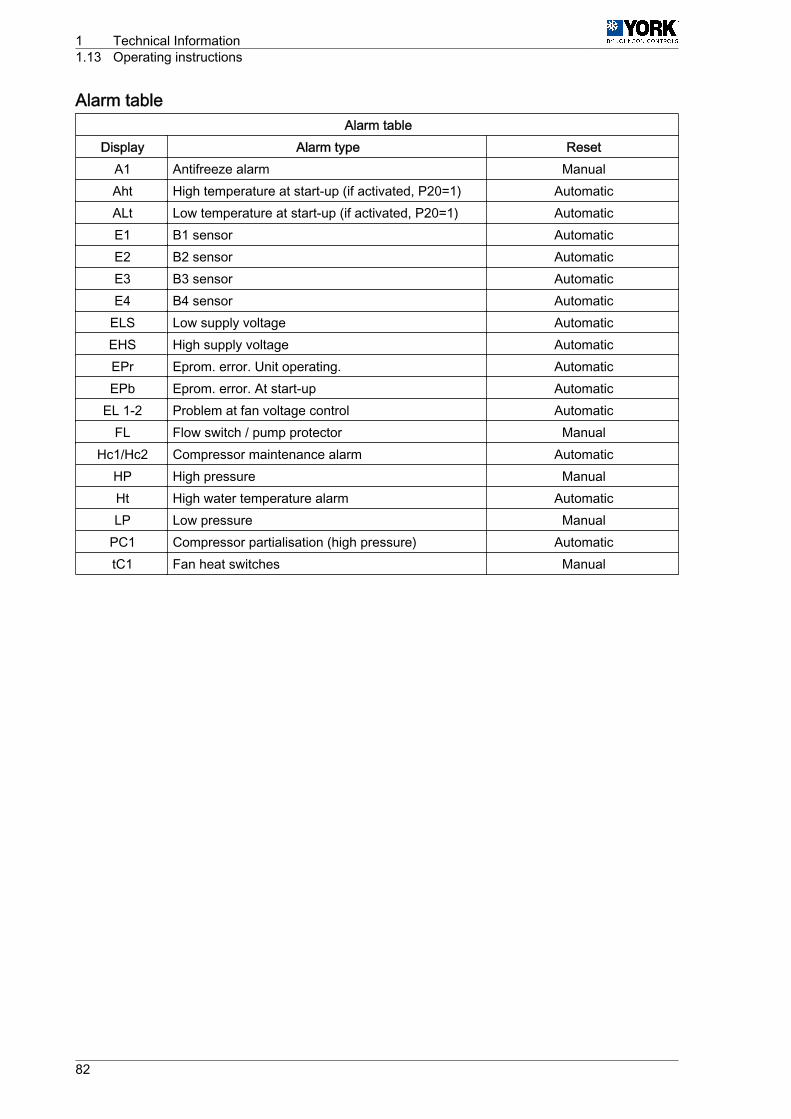
Alarm tableAlarm table
Display Alarm type ResetA1 Antifreeze alarm ManualAht High temperature at start-up (if activated, P20=1) AutomaticALt Low temperature at start-up (if activated, P20=1) AutomaticE1 B1 sensor AutomaticE2 B2 sensor AutomaticE3 B3 sensor AutomaticE4 B4 sensor Automatic
ELS Low supply voltage AutomaticEHS High supply voltage AutomaticEPr Eprom. error. Unit operating. AutomaticEPb Eprom. error. At start-up Automatic
EL 1-2 Problem at fan voltage control AutomaticFL Flow switch / pump protector Manual
Hc1/Hc2 Compressor maintenance alarm AutomaticHP High pressure ManualHt High water temperature alarm AutomaticLP Low pressure Manual
PC1 Compressor partialisation (high pressure) AutomatictC1 Fan heat switches Manual
1 Technical Information1.13 Operating instructions
82
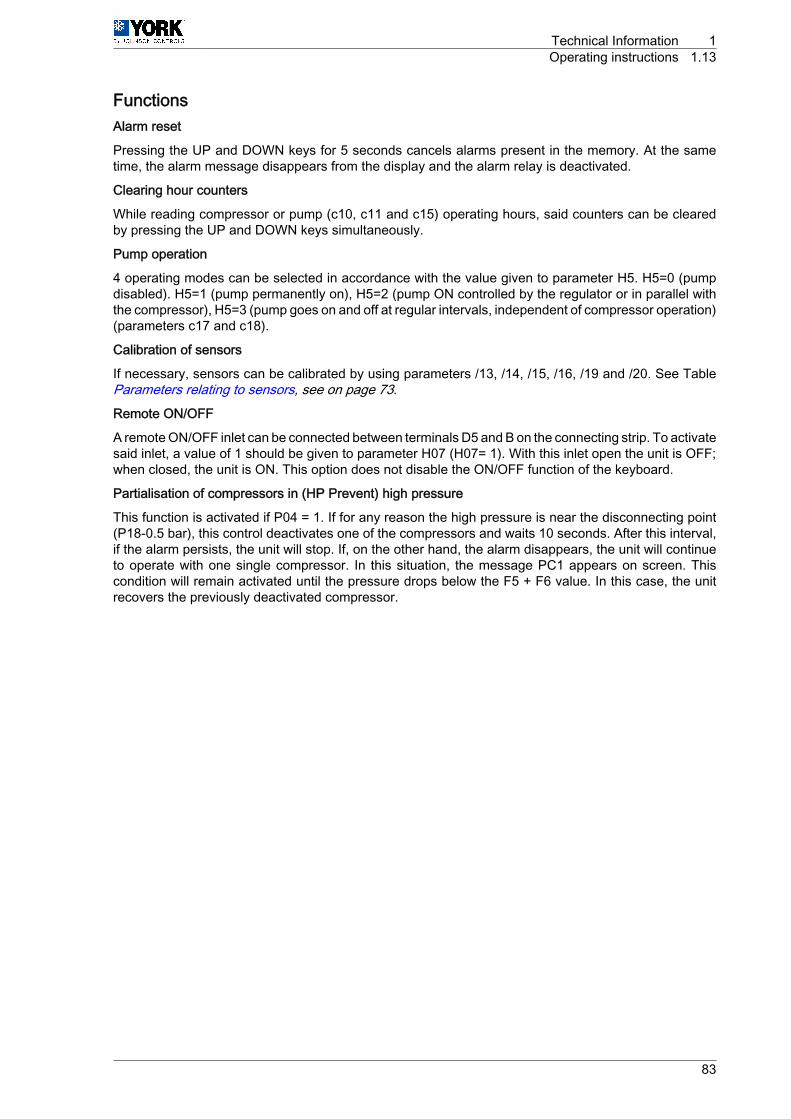
FunctionsAlarm reset
Pressing the UP and DOWN keys for 5 seconds cancels alarms present in the memory. At the sametime, the alarm message disappears from the display and the alarm relay is deactivated.
Clearing hour counters
While reading compressor or pump (c10, c11 and c15) operating hours, said counters can be clearedby pressing the UP and DOWN keys simultaneously.
Pump operation
4 operating modes can be selected in accordance with the value given to parameter H5. H5=0 (pumpdisabled). H5=1 (pump permanently on), H5=2 (pump ON controlled by the regulator or in parallel withthe compressor), H5=3 (pump goes on and off at regular intervals, independent of compressor operation)(parameters c17 and c18).
Calibration of sensors
If necessary, sensors can be calibrated by using parameters /13, /14, /15, /16, /19 and /20. See TableParameters relating to sensors, see on page 73.
Remote ON/OFF
A remote ON/OFF inlet can be connected between terminals D5 and B on the connecting strip. To activatesaid inlet, a value of 1 should be given to parameter H07 (H07= 1). With this inlet open the unit is OFF;when closed, the unit is ON. This option does not disable the ON/OFF function of the keyboard.
Partialisation of compressors in (HP Prevent) high pressure
This function is activated if P04 = 1. If for any reason the high pressure is near the disconnecting point(P18-0.5 bar), this control deactivates one of the compressors and waits 10 seconds. After this interval,if the alarm persists, the unit will stop. If, on the other hand, the alarm disappears, the unit will continueto operate with one single compressor. In this situation, the message PC1 appears on screen. Thiscondition will remain activated until the pressure drops below the F5 + F6 value. In this case, the unitrecovers the previously deactivated compressor.
Technical Information 1Operating instructions 1.13
83
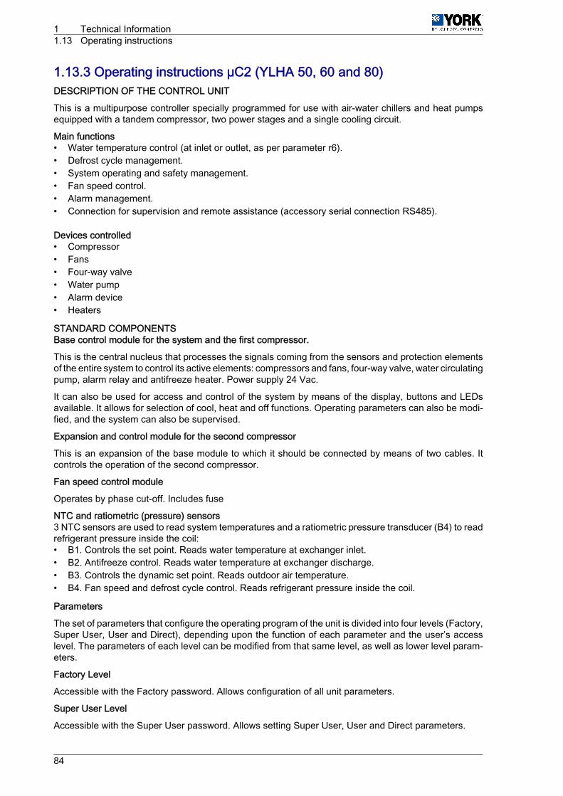
1.13.3 Operating instructions µC2 (YLHA 50, 60 and 80)DESCRIPTION OF THE CONTROL UNIT
This is a multipurpose controller specially programmed for use with air-water chillers and heat pumpsequipped with a tandem compressor, two power stages and a single cooling circuit.
Main functions• Water temperature control (at inlet or outlet, as per parameter r6).• Defrost cycle management.• System operating and safety management.• Fan speed control.• Alarm management.• Connection for supervision and remote assistance (accessory serial connection RS485).
Devices controlled• Compressor• Fans• Four-way valve• Water pump• Alarm device• Heaters
STANDARD COMPONENTSBase control module for the system and the first compressor.
This is the central nucleus that processes the signals coming from the sensors and protection elementsof the entire system to control its active elements: compressors and fans, four-way valve, water circulatingpump, alarm relay and antifreeze heater. Power supply 24 Vac.
It can also be used for access and control of the system by means of the display, buttons and LEDsavailable. It allows for selection of cool, heat and off functions. Operating parameters can also be modi‐fied, and the system can also be supervised.
Expansion and control module for the second compressor
This is an expansion of the base module to which it should be connected by means of two cables. Itcontrols the operation of the second compressor.
Fan speed control module
Operates by phase cut-off. Includes fuse
NTC and ratiometric (pressure) sensors3 NTC sensors are used to read system temperatures and a ratiometric pressure transducer (B4) to readrefrigerant pressure inside the coil:• B1. Controls the set point. Reads water temperature at exchanger inlet.• B2. Antifreeze control. Reads water temperature at exchanger discharge.• B3. Controls the dynamic set point. Reads outdoor air temperature.• B4. Fan speed and defrost cycle control. Reads refrigerant pressure inside the coil.
Parameters
The set of parameters that configure the operating program of the unit is divided into four levels (Factory,Super User, User and Direct), depending upon the function of each parameter and the user’s accesslevel. The parameters of each level can be modified from that same level, as well as lower level param‐eters.
Factory Level
Accessible with the Factory password. Allows configuration of all unit parameters.
Super User Level
Accessible with the Super User password. Allows setting Super User, User and Direct parameters.
1 Technical Information1.13 Operating instructions
84

User Level
Accessible with password 22. Allows access to all parameters the user normally sets.
Direct Level
Accessible without a password. Allows for reading of the values detected by the sensors, as well as othersystem values. Can be used by the user without affecting unit operation.
General
Modification of the parameters that affect basic unit configuration should be made with the controller inStandby position.
Technical Information 1Operating instructions 1.13
85
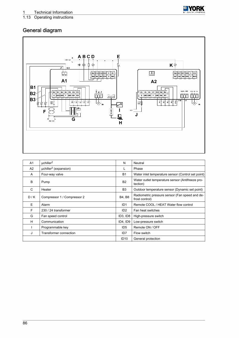
General diagram
A1 µchiller2 N Neutral
A2 µchiller2 (expansion) L Phase
A Four-way valve B1 Water inlet temperature sensor (Control set point)
B Pump B2 Water outlet temperature sensor (Antifreeze pro‐tection)
C Heater B3 Outdoor temperature sensor (Dynamic set point)
D / K Compressor 1 / Compressor 2 B4, B8 Radiometric pressure sensor (Fan speed and de‐frost control)
E Alarm ID1 Remote COOL / HEAT Water flow control
F 230 / 24 transformer ID2 Fan heat switches
G Fan speed control ID3, ID8 High-pressure switch
H Communication ID4, ID9 Low-pressure switch
I Programmable key ID5 Remote ON / OFF
J Transformer connection ID7 Flow switch
ID10 General protection
1 Technical Information1.13 Operating instructions
86
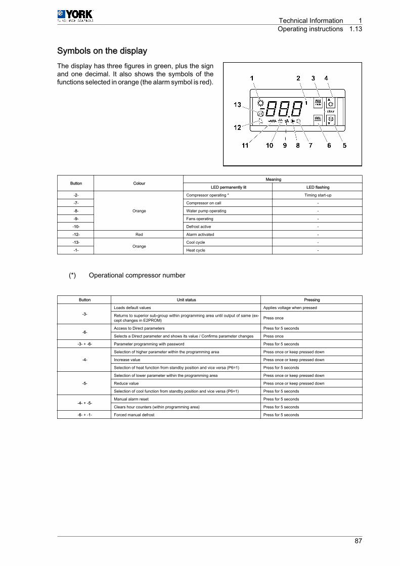
Symbols on the displayThe display has three figures in green, plus the signand one decimal. It also shows the symbols of thefunctions selected in orange (the alarm symbol is red).
Button ColourMeaning
LED permanently lit LED flashing
-2-
Orange
Compressor operating * Timing start-up
-7- Compressor on call -
-8- Water pump operating -
-9- Fans operating -
-10- Defrost active -
-12- Red Alarm activated -
-13-Orange
Cool cycle -
-1- Heat cycle -
(*) Operational compressor number
Button Unit status Pressing
-3-Loads default values Applies voltage when pressed
Returns to superior sub-group within programming area until output of same (ex‐cept changes in E2PROM) Press once
-6-Access to Direct parameters Press for 5 seconds
Selects a Direct parameter and shows its value / Confirms parameter changes Press once
-3- + ‑6- Parameter programming with password Press for 5 seconds
-4-
Selection of higher parameter within the programming area Press once or keep pressed down
Increase value Press once or keep pressed down
Selection of heat function from standby position and vice versa (P6=1) Press for 5 seconds
-5-
Selection of lower parameter within the programming area Press once or keep pressed down
Reduce value Press once or keep pressed down
Selection of cool function from standby position and vice versa (P6=1) Press for 5 seconds
-4- + ‑5-Manual alarm reset Press for 5 seconds
Clears hour counters (within programming area) Press for 5 seconds
-6- + ‑1- Forced manual defrost Press for 5 seconds
Technical Information 1Operating instructions 1.13
87
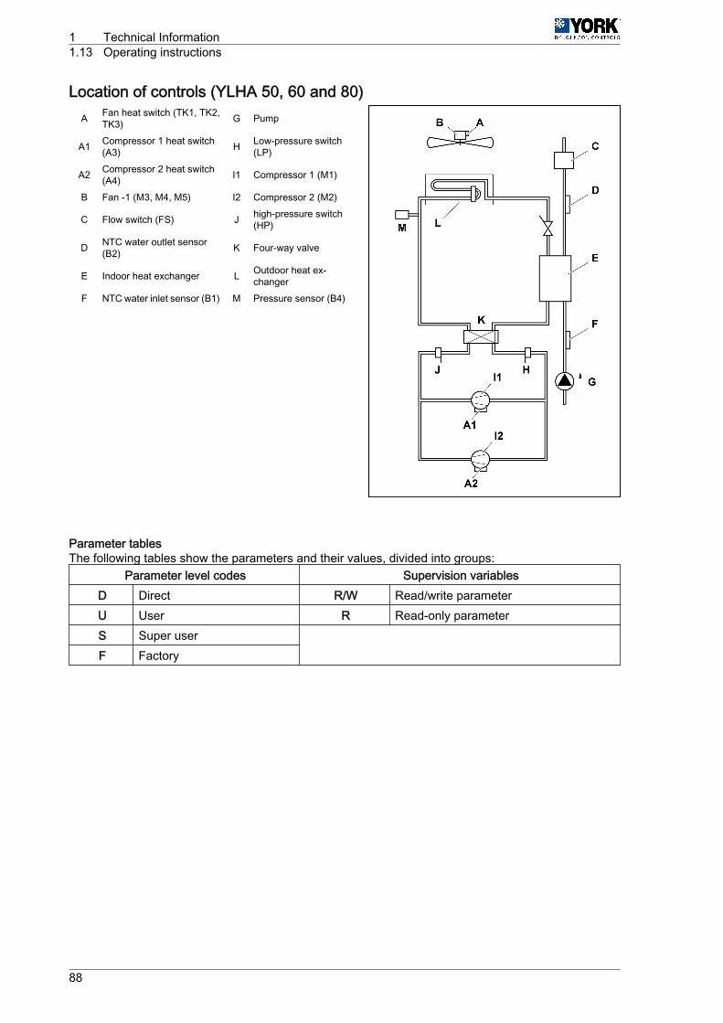
Location of controls (YLHA 50, 60 and 80)A Fan heat switch (TK1, TK2,
TK3) G Pump
A1 Compressor 1 heat switch(A3) H Low-pressure switch
(LP)
A2 Compressor 2 heat switch(A4) I1 Compressor 1 (M1)
B Fan ‑1 (M3, M4, M5) I2 Compressor 2 (M2)
C Flow switch (FS) J high-pressure switch(HP)
D NTC water outlet sensor(B2) K Four-way valve
E Indoor heat exchanger L Outdoor heat ex‐changer
F NTC water inlet sensor (B1) M Pressure sensor (B4)
Parameter tablesThe following tables show the parameters and their values, divided into groups:
Parameter level codes Supervision variablesD Direct R/W Read/write parameterU User R Read-only parameterS Super user
F Factory
1 Technical Information1.13 Operating instructions
88
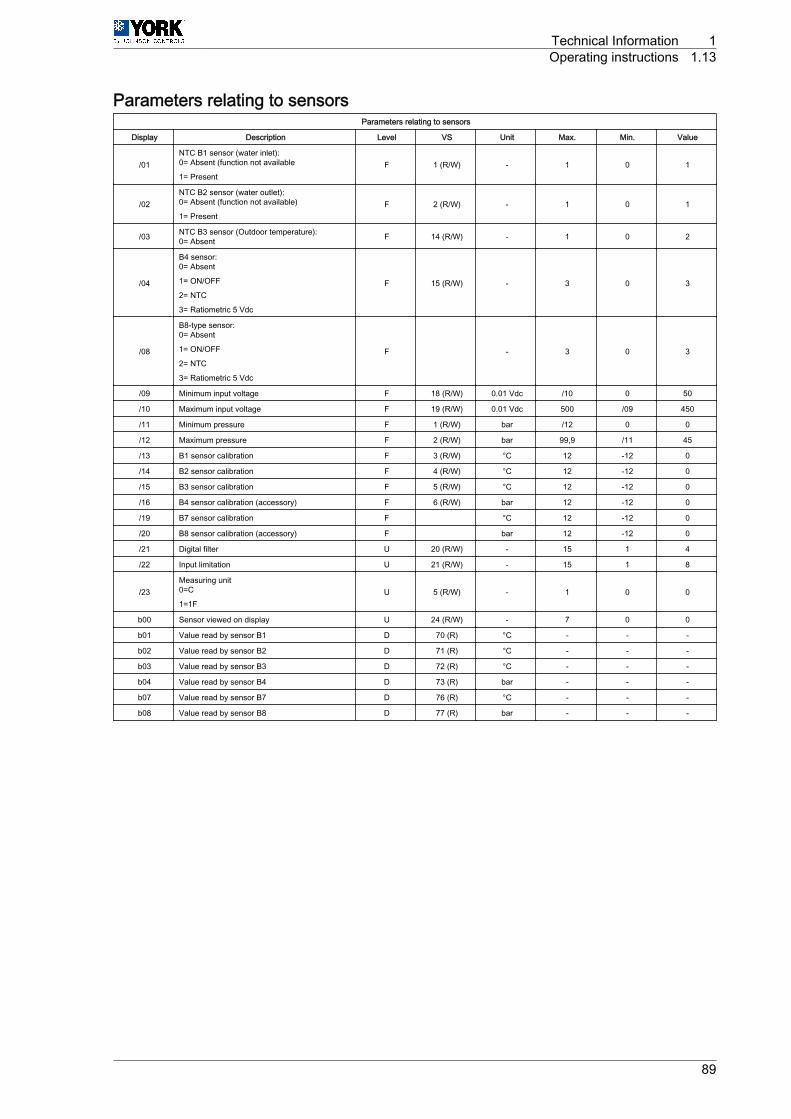
Parameters relating to sensorsParameters relating to sensors
Display Description Level VS Unit Max. Min. Value
/01NTC B1 sensor (water inlet):0= Absent (function not available
1= PresentF 1 (R/W) - 1 0 1
/02NTC B2 sensor (water outlet):0= Absent (function not available)
1= PresentF 2 (R/W) - 1 0 1
/03 NTC B3 sensor (Outdoor temperature):0= Absent F 14 (R/W) - 1 0 2
/04
B4 sensor:0= Absent
1= ON/OFF
2= NTC
3= Ratiometric 5 Vdc
F 15 (R/W) - 3 0 3
/08
B8-type sensor:0= Absent
1= ON/OFF
2= NTC
3= Ratiometric 5 Vdc
F - 3 0 3
/09 Minimum input voltage F 18 (R/W) 0.01 Vdc /10 0 50
/10 Maximum input voltage F 19 (R/W) 0.01 Vdc 500 /09 450
/11 Minimum pressure F 1 (R/W) bar /12 0 0
/12 Maximum pressure F 2 (R/W) bar 99,9 /11 45
/13 B1 sensor calibration F 3 (R/W) °C 12 -12 0
/14 B2 sensor calibration F 4 (R/W) °C 12 -12 0
/15 B3 sensor calibration F 5 (R/W) °C 12 -12 0
/16 B4 sensor calibration (accessory) F 6 (R/W) bar 12 -12 0
/19 B7 sensor calibration F °C 12 -12 0
/20 B8 sensor calibration (accessory) F bar 12 -12 0
/21 Digital filter U 20 (R/W) - 15 1 4
/22 Input limitation U 21 (R/W) - 15 1 8
/23Measuring unit0=C
1=1FU 5 (R/W) - 1 0 0
b00 Sensor viewed on display U 24 (R/W) - 7 0 0
b01 Value read by sensor B1 D 70 (R) °C - - -
b02 Value read by sensor B2 D 71 (R) °C - - -
b03 Value read by sensor B3 D 72 (R) °C - - -
b04 Value read by sensor B4 D 73 (R) bar - - -
b07 Value read by sensor B7 D 76 (R) °C - - -
b08 Value read by sensor B8 D 77 (R) bar - - -
Technical Information 1Operating instructions 1.13
89
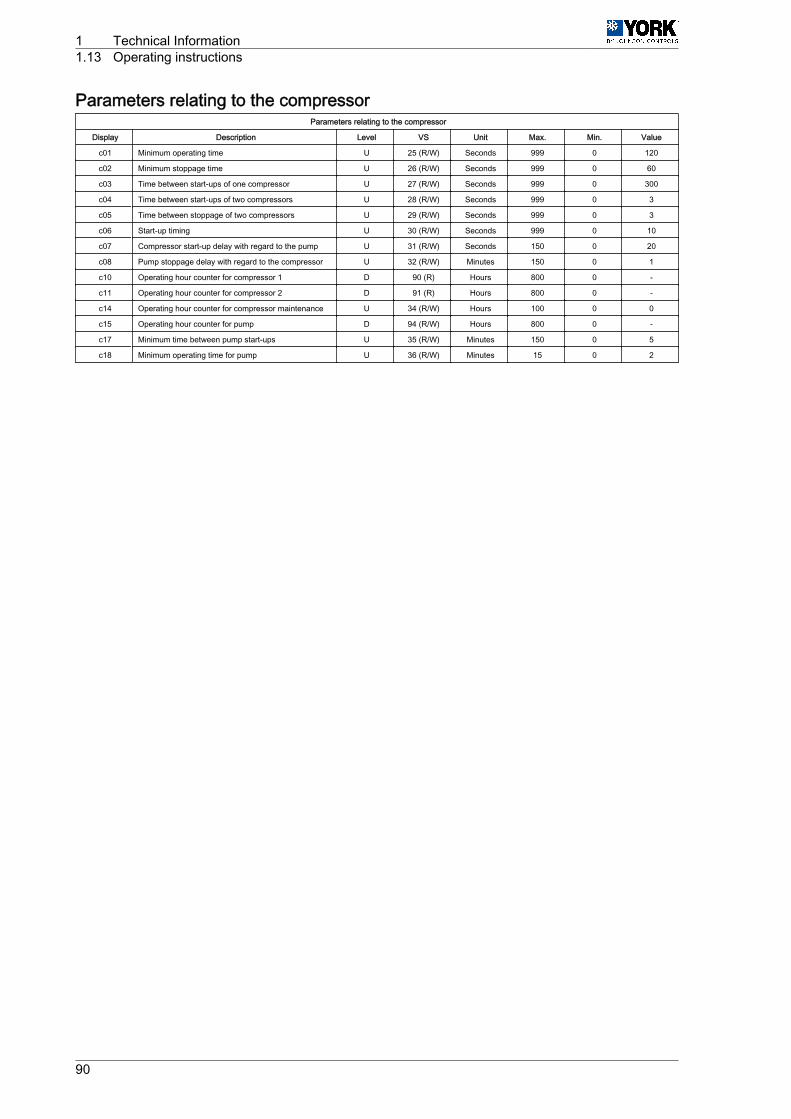
Parameters relating to the compressorParameters relating to the compressor
Display Description Level VS Unit Max. Min. Value
c01 Minimum operating time U 25 (R/W) Seconds 999 0 120
c02 Minimum stoppage time U 26 (R/W) Seconds 999 0 60
c03 Time between start-ups of one compressor U 27 (R/W) Seconds 999 0 300
c04 Time between start-ups of two compressors U 28 (R/W) Seconds 999 0 3
c05 Time between stoppage of two compressors U 29 (R/W) Seconds 999 0 3
c06 Start-up timing U 30 (R/W) Seconds 999 0 10
c07 Compressor start-up delay with regard to the pump U 31 (R/W) Seconds 150 0 20
c08 Pump stoppage delay with regard to the compressor U 32 (R/W) Minutes 150 0 1
c10 Operating hour counter for compressor 1 D 90 (R) Hours 800 0 -
c11 Operating hour counter for compressor 2 D 91 (R) Hours 800 0 -
c14 Operating hour counter for compressor maintenance U 34 (R/W) Hours 100 0 0
c15 Operating hour counter for pump D 94 (R/W) Hours 800 0 -
c17 Minimum time between pump start-ups U 35 (R/W) Minutes 150 0 5
c18 Minimum operating time for pump U 36 (R/W) Minutes 15 0 2
1 Technical Information1.13 Operating instructions
90
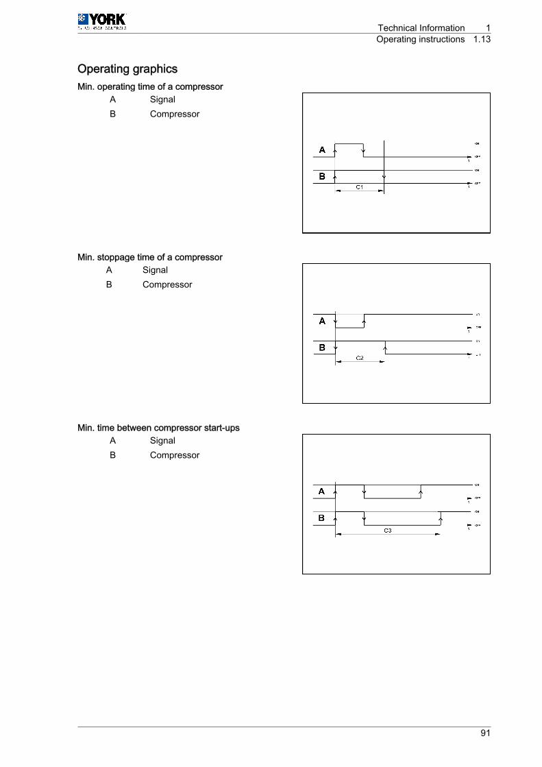
Operating graphicsMin. operating time of a compressor
A SignalB Compressor
Min. stoppage time of a compressorA SignalB Compressor
Min. time between compressor start-upsA SignalB Compressor
Technical Information 1Operating instructions 1.13
91

Min. time between start-up of two compressorsA Signal 1 C Compressor 1B Signal 2 D Compressor 2
Time between stoppage of two compressorsA Signal 1 C Compressor 1B Signal 2 D Compressor 2
Compressor / pump stoppage delaysA CompressorB Pump
1 Technical Information1.13 Operating instructions
92
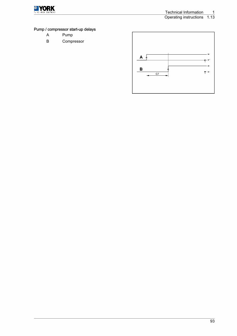
Pump / compressor start-up delaysA PumpB Compressor
Technical Information 1Operating instructions 1.13
93
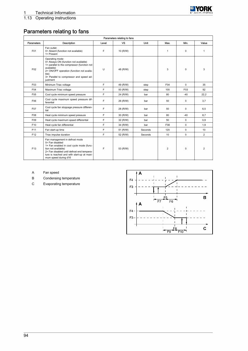
Parameters relating to fansParameters relating to fans
Parameters Description Level VS Unit Max. Min. Value
F01Fan outlet:0= Absent (function not available)1= Present
F 10 (R/W) 1 0 1
F02
Operating mode:0= Always ON (function not available)1= parallel to the compressor (function notavailable)2= ON/OFF operation (function not availa‐ble)3= Parallel to compressor and speed ad‐justment
U 48 (R/W) 3 0 3
F03 Minimum Triac voltage F 49 (R/W) step F04 0 35
F04 Maximum Triac voltage F 50 (R/W) step 100 F03 92
F05 Cool cycle minimum speed pressure F 24 (R/W) bar 80 -40 22,2
F06 Cool cycle maximum speed pressure dif‐ferential F 26 (R/W) bar 50 0 3,7
F07 Cool cycle fan stoppage pressure differen‐tial F 28 (R/W) bar 50 0 6,5
F08 Heat cycle minimum speed pressure F 30 (R/W) bar 80 -40 8,7
F09 Heat cycle maximum speed differential F 32 (R/W) bar 50 0 0,9
F10 Heat cycle fan differential F 34 (R/W) bar F08 0 1,9
F11 Fan start-up time F 51 (R/W) Seconds 120 0 10
F12 Triac impulse duration F 52 (R/W) Seconds 10 0 2
F13
Fan management in defrost mode0= Fan disabled1= Fan enabled in cool cycle mode (func‐tion not available)2= Fan disabled until defrost end tempera‐ture is reached and with start-up at maxi‐mum speed during d16
F 53 (R/W) 2 0 2
A Fan speedB Condensing temperatureC Evaporating temperature
1 Technical Information1.13 Operating instructions
94
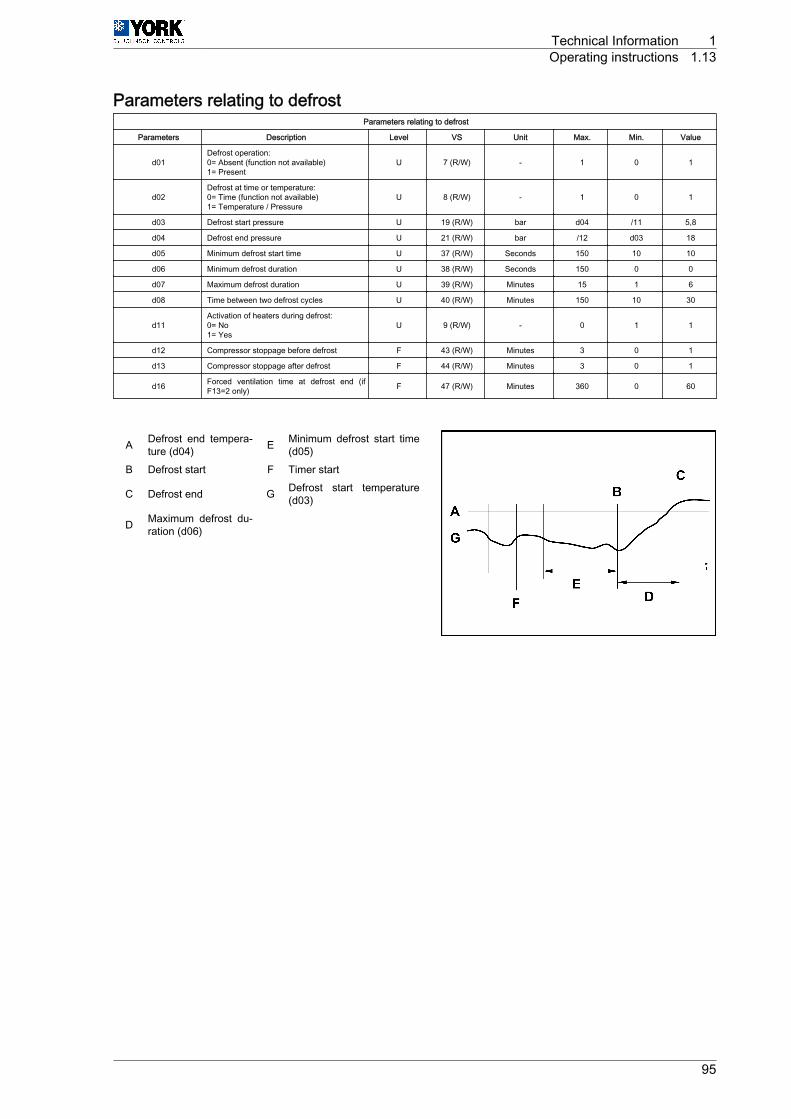
Parameters relating to defrostParameters relating to defrost
Parameters Description Level VS Unit Max. Min. Value
d01Defrost operation:0= Absent (function not available)1= Present
U 7 (R/W) - 1 0 1
d02Defrost at time or temperature:0= Time (function not available)1= Temperature / Pressure
U 8 (R/W) - 1 0 1
d03 Defrost start pressure U 19 (R/W) bar d04 /11 5,8
d04 Defrost end pressure U 21 (R/W) bar /12 d03 18
d05 Minimum defrost start time U 37 (R/W) Seconds 150 10 10
d06 Minimum defrost duration U 38 (R/W) Seconds 150 0 0
d07 Maximum defrost duration U 39 (R/W) Minutes 15 1 6
d08 Time between two defrost cycles U 40 (R/W) Minutes 150 10 30
d11Activation of heaters during defrost:0= No1= Yes
U 9 (R/W) - 0 1 1
d12 Compressor stoppage before defrost F 43 (R/W) Minutes 3 0 1
d13 Compressor stoppage after defrost F 44 (R/W) Minutes 3 0 1
d16 Forced ventilation time at defrost end (ifF13=2 only) F 47 (R/W) Minutes 360 0 60
A Defrost end tempera‐ture (d04) E Minimum defrost start time
(d05)B Defrost start F Timer start
C Defrost end G Defrost start temperature(d03)
D Maximum defrost du‐ration (d06)
Technical Information 1Operating instructions 1.13
95
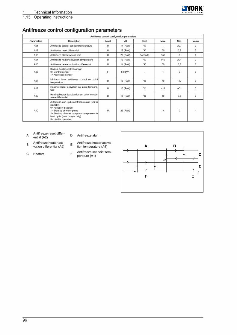
Antifreeze control configuration parametersAntifreeze control configuration parameters
Parameters Description Level VS Unit Max. Min. Value
A01 Antifreeze control set point temperature U 11 (R/W) °C - A07 3
A02 Antifreeze reset differential U 12 (R/W) °K 50 0,3 5
A03 Antifreeze alarm bypass time U 22 (R/W) Seconds 150 0 0
A04 Antifreeze heater activation temperature U 13 (R/W) °C r16 A01 3
A05 Antifreeze heater activation differential U 14 (R/W) °K 50 0,3 2
A06Backup heater control sensor:0= Control sensor1= Antifreeze sensor
F 6 (R/W) - 1 0 0
A07 Minimum level antifreeze control set pointtemperature U 15 (R/W) °C 79 -40 3
A08 Heating heater activation set point tempera‐ture U 16 (R/W) °C r15 A01 3
A09 Heating heater deactivation set point temper‐ature differential U 17 (R/W) °C 50 0,3 3
A10
Automatic start-up by antifreeze alarm (unit instandby):0= Function disabled1= Start-up of water pump2= Start-up of water pump and compressor inheat cycle (heat pumps only)3= Heater operative
U 23 (R/W) 3 0 1
A Antifreeze reset differ‐ential (A2) D Antifreeze alarm
B Antifreeze heater acti‐vation differential (A5) E Antifreeze heater activa‐
tion temperature (A4)
C Heaters F Antifreeze set point tem‐perature (A1)
1 Technical Information1.13 Operating instructions
96

Unit configuration parametersUnit configuration parameters
Display Description Level VS Unit Max. Min. Value
H01Unit model:2= Water chiller
3= Air-water heat pumpF 54 (R/W) 3
H02 Number of vent circuits (do not modify this parameter) F 12 (R/W) 0
H03 No. of evaporating units present (do not modify thisparameter) F 13 (R/W) 0
H04 No. of compressors per circuit (do not modify this pa‐rameter) F 55 (R/W) 2
H05
Pump operation:0= Absent
1= Always ON
2= ON upon controller call
3= ON upon controller and time call
F 56 (R/W) 3 0 1
H06COOL/HEAT digital input:0= Absent
1= PresentU 14 (R/W) 1 0 0
H07ON/OFF digital input:0= Absent
1= PresentU 15 (R/W) 1 0 0
H08 Network configuration (do not modify this parameter) F 57 (R/W) 3 0 2
H09Keyboard locked:0= Disabled
1= EnabledU 16 (R/W) 1 0 1
H10 Serial direction for monitoring:0= Future use as terminal U 58 (R/W) 200 1 1
H11 Output configuration (not selectable) F 59 (R/W) 3 0 0
H12 4-way valve logic operation. Activated in cold cycle (donot modify this parameter) F 60 (R/W) 3 0 0
H21 Second pump function (do not modify this parameter) F 62 (R/W) 4 0 0
H22Default parameter loading disabled:0= Disabled
1= EnabledF 18 (R/W) 1 0 1
H23Modbus protocol setting:0= Disabled
1= EnabledF 11 1 0 0
Technical Information 1Operating instructions 1.13
97
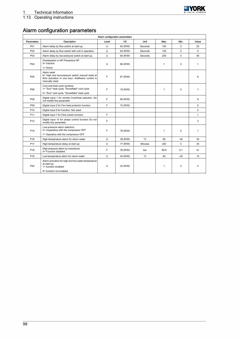
Alarm configuration parametersAlarm configuration parameters
Parameters Description Level VS Unit Max. Min. Value
P01 Alarm delay by flow switch at start-up. U 63 (R/W) Seconds 150 0 20
P02 Alarm delay by flow switch with unit in operation. U 64 (R/W) Seconds 120 0 5
P03 Alarm delay by low-pressure switch at start-up. U 65 (R/W) Seconds 200 0 60
P04Partialisation in HP Preventive HP0= Inactive
1= ActiveU 66 (R/W) 1 0 1
P05
Alarm reset6= High and low-pressure switch manual reset atthird activation in one hour. Antifreeze control ismanually reset
F 67 (R/W) 6
P06Cool and heat cycle symbols.1= "Sun" heat cycle, "Snowflake" cool cycle
0= "Sun" cool cycle, "Snowflake" heat cycleF 19 (R/W) 1 0 1
P08 Digital input 1 for remote Cool/Heat selection. Donot modify this parameter F 69 (R/W) 9
P09 Digital input 2 for Fan heat protector function F 70 (R/W) 6
P10 Digital input 6 for function. Not used. 0
P11 Digital input 7 for Flow switch function F 1
P12 Digital input 10 for phase control function Do notmodify this parameter F 3
P15Low-pressure alarm selection.0= Inoperative with the compressor OFF
1= Operative with the compressor OFFF 76 (R/W) 1 0 1
P16 High-temperature alarm for return water U 38 (R/W) °C 80 -40 30
P17 High-temperature delay at start-up U 77 (R/W) Minutes 250 0 30
P18 High-pressure alarm by transducer0= Function disabled F 39 (R/W) bar 99,9 0,1 41
P19 Low-temperature alarm for return water U 40 (R/W) °C 80 -40 10
P20
Alarm activation for high and low water temperatureat start-up.1= function enabled
0= function not enabled
U 20 (R/W) 1 0 0
1 Technical Information1.13 Operating instructions
98
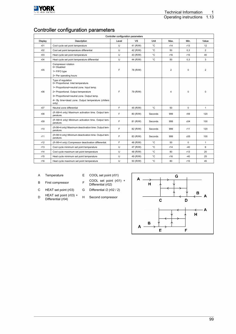
Controller configuration parametersController configuration parameters
Display Description Level VS Unit Max. Min. Value
r01 Cool cycle set point temperature U 41 (R/W) °C r14 r13 12
r02 Cool set point temperature differential U 42 (R/W) °C 50 0,3 2
r03 Heat cycle set point temperature U 43 (R/W) °C r16 r15 40
r04 Heat cycle set point temperature differential U 44 (R/W) °C 50 0,3 3
r05
Compressor rotation0= Disabled
1= FIFO type
2= Per operating hours
F 78 (R/W) 2 0 2
r06
Type of regulation0= Proportional. Inlet temperature.
1= Proportional+neutral zone. Input temp.
2= Proportional. Output temperature
3= Proportional+neutral zone. Output temp.
4= By time+dead zone. Output temperature (chillersonly)
F 79 (R/W) 4 0 0
r07 Neutral zone differential F 45 (R/W) °C 50 0 1
r08 (If r06=4 only) Maximum activation time. Output tem‐perature. F 80 (R/W) Seconds 999 r09 120
r09 (If r06=4 only) Minimum activation time. Output tem‐perature. F 81 (R/W) Seconds 999 c04 100
r10 (If r06=4 only) Maximum deactivation time. Output tem‐perature. F 82 (R/W) Seconds 999 r11 120
r11 (If r06=4 only) Minimum deactivation time. Output tem‐perature. F 83 (R/W) Seconds 999 c05 100
r12 (If r06=4 only) Compressor deactivation differential. F 46 (R/W) °C 50 0 1
r13 Cool cycle minimum set point temperature U 47 (R/W) °C r14 -40 6
r14 Cool cycle maximum set point temperature U 48 (R/W) °C 80 r13 20
r15 Heat cycle minimum set point temperature U 49 (R/W) °C r16 -40 25
r16 Heat cycle maximum set point temperature U 50 (R/W) °C 80 r15 45
A Temperature E COOL set point (r01)
B First compressor F COOL set point (r01) +Differential (r02)
C HEAT set point (r03) G Differential /2 (r02 / 2)
D HEAT set point (r03) +Differential (r04) H Second compressor
Technical Information 1Operating instructions 1.13
99

Alarm tableAlarm table
Display Alarm type ResetA1 Antifreeze alarm ManualAht High temperature at start-up (if activated, P20=1) AutomaticALt Low temperature at start-up (if activated, P20=1) Automaticd1-2 Defrost operating -
dF1-2 Problem in defrost AutomaticE1 B1 sensor AutomaticE2 B2 sensor AutomaticE3 B3 sensor AutomaticE4 B4 sensor AutomaticE8 B8 sensor Automatic
ELS Low supply voltage AutomaticEHS High supply voltage AutomaticEPr Eprom. error. Unit operating. AutomaticEPb Eprom. error. At start-up AutomaticESP Communication failure with expansion module Automatic
EL 1-2 Problem at fan voltage control AutomaticFL Flow switch Manual
Hc1/Hc2 Compressor maintenance alarm AutomaticHP1/HP2 High pressure Manual
Ht High water temperature alarm AutomaticLP1/LP2 Low pressure Manual
PC1 Compressor partialisation (high pressure) AutomatictC1 Fan heat switches AutomaticTP Phase order fault/phase fault Manual
1 Technical Information1.13 Operating instructions
100
FunctionsAlarm reset
Pressing the UP and DOWN keys for 5 seconds cancels alarms present in the memory. At the sametime, the alarm message disappears from the display and the alarm relay is deactivated.
Forced defrost (heat pumps)
Pressing the SEL and UP keys simultaneously for 5 seconds activates forced defrost of the unit.
Clearing hour counters
While reading compressor or pump (c10, c11 and c15) operating hours, said counters can be clearedby pressing the UP and DOWN keys simultaneously.
Pump operation
4 operating modes can be selected in accordance with the value given to parameter H5. H5=0 (pumpdisabled). H5=1 (pump permanently on), H5=2 (pump ON controlled by the regulator or in parallel withthe compressor), H5=3 (pump goes on and off at regular intervals, independent of compressor operation)(parameters c17 and c18).
Calibration of sensors
If necessary, sensors can be calibrated by using parameters /13, /14, /15, /16, /19 and /20. See TableParameters relating to sensors, see on page 89.
Remote ON/OFF
A remote ON/OFF inlet can be connected between terminals D5 and B on the connecting strip. To activatesaid inlet, a value of 1 should be given to parameter H07 (H07= 1). With this inlet open the unit is OFF;when closed, the unit is ON. This option does not disable the ON/OFF function of the keyboard.
Remote COOL/HEAT
A remote COOL/HEAT inlet can be connected between terminals D2 and B on the connecting strip. Toactivate said inlet, a value of 1 should be given to parameter H06 (H06= 1). With this inlet open the unitis in HEAT; when closed, the unit is in COOL. This function disables the COOL/HEAT function of thekeyboard.
Partialisation of compressors in (HP Prevent) high pressure
This function is activated if P04 = 1. If for any reason the high pressure is near the disconnecting point(P18-0.5 bar), this control deactivates one of the compressors and waits 10 seconds. After this interval,if the alarm persists, the unit will stop. If, on the other hand, the alarm disappears, the unit will continueto operate with one single compressor. In this situation, the message PC1 appears on screen. Thiscondition will remain activated until the pressure drops below the F5 + F6 value. In this case, the unitrecovers the previously deactivated compressor.
Technical Information 1Operating instructions 1.13
101
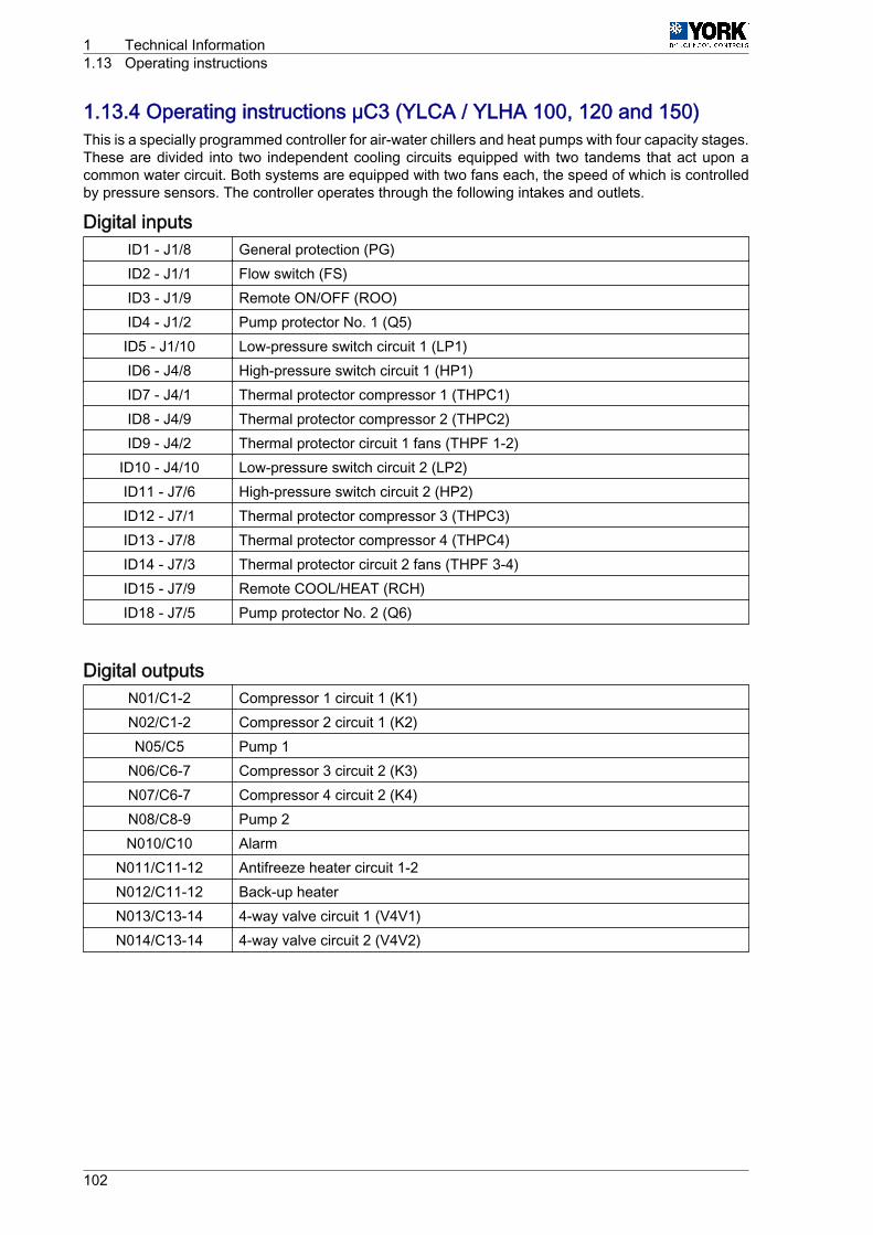
1.13.4 Operating instructions µC3 (YLCA / YLHA 100, 120 and 150)This is a specially programmed controller for air-water chillers and heat pumps with four capacity stages.These are divided into two independent cooling circuits equipped with two tandems that act upon acommon water circuit. Both systems are equipped with two fans each, the speed of which is controlledby pressure sensors. The controller operates through the following intakes and outlets.
Digital inputsID1 ‑ J1/8 General protection (PG)ID2 ‑ J1/1 Flow switch (FS)ID3 ‑ J1/9 Remote ON/OFF (ROO)ID4 ‑ J1/2 Pump protector No. 1 (Q5)
ID5 ‑ J1/10 Low-pressure switch circuit 1 (LP1)ID6 ‑ J4/8 High-pressure switch circuit 1 (HP1)ID7 ‑ J4/1 Thermal protector compressor 1 (THPC1)ID8 ‑ J4/9 Thermal protector compressor 2 (THPC2)ID9 ‑ J4/2 Thermal protector circuit 1 fans (THPF 1-2)
ID10 ‑ J4/10 Low-pressure switch circuit 2 (LP2)ID11 ‑ J7/6 High-pressure switch circuit 2 (HP2)ID12 ‑ J7/1 Thermal protector compressor 3 (THPC3)ID13 ‑ J7/8 Thermal protector compressor 4 (THPC4)ID14 ‑ J7/3 Thermal protector circuit 2 fans (THPF 3-4)ID15 ‑ J7/9 Remote COOL/HEAT (RCH)ID18 ‑ J7/5 Pump protector No. 2 (Q6)
Digital outputsN01/C1-2 Compressor 1 circuit 1 (K1)N02/C1-2 Compressor 2 circuit 1 (K2)N05/C5 Pump 1
N06/C6-7 Compressor 3 circuit 2 (K3)N07/C6-7 Compressor 4 circuit 2 (K4)N08/C8-9 Pump 2N010/C10 Alarm
N011/C11-12 Antifreeze heater circuit 1-2N012/C11-12 Back-up heaterN013/C13-14 4-way valve circuit 1 (V4V1)N014/C13-14 4-way valve circuit 2 (V4V2)
1 Technical Information1.13 Operating instructions
102

Analogue inputsB3 ‑ J2 Coil pressure circuit 1B4 ‑ J3 Coil pressure circuit 2
B5 ‑ J4/13 Water temperature at exchanger inletB6 ‑ J4/12 Water temperature at exchanger outlet
Analogue outputsY3 Circuit 1 fan speed control (PWM)Y4 Circuit 2 fan speed control (PWM)
Technical Information 1Operating instructions 1.13
103
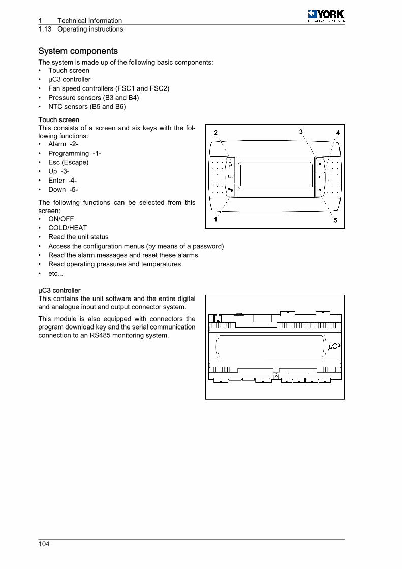
System componentsThe system is made up of the following basic components:• Touch screen• µC3 controller• Fan speed controllers (FSC1 and FSC2)• Pressure sensors (B3 and B4)• NTC sensors (B5 and B6)
Touch screenThis consists of a screen and six keys with the fol‐lowing functions:• Alarm ‑2-• Programming ‑1-• Esc (Escape)• Up ‑3-• Enter ‑4-• Down ‑5-
The following functions can be selected from thisscreen:• ON/OFF• COLD/HEAT• Read the unit status• Access the configuration menus (by means of a password)• Read the alarm messages and reset these alarms• Read operating pressures and temperatures• etc...
µC3 controllerThis contains the unit software and the entire digitaland analogue input and output connector system.
This module is also equipped with connectors theprogram download key and the serial communicationconnection to an RS485 monitoring system.
1 Technical Information1.13 Operating instructions
104

Sensors and probes
Pressure sensors (B3 and B4)
One for each cooling circuit and connector to the coil collectors. They provide information to the systemfor fan speed adjustment in the summer and winter cycles, management of defrosts in the heat pumps,prevent and lockout functions of the system by excessively high pressure.
NTC probes(B5 and B6)• B5- For the detection and control of water inlet temperature (cool only and heat pump units).• B6- For the detection of water outlet temperature. It provides information for antifreeze protection and
control of the antifreeze and backup heaters. If required, allows controlling water temperature at theheat exchanger discharge
Technical Information 1Operating instructions 1.13
105
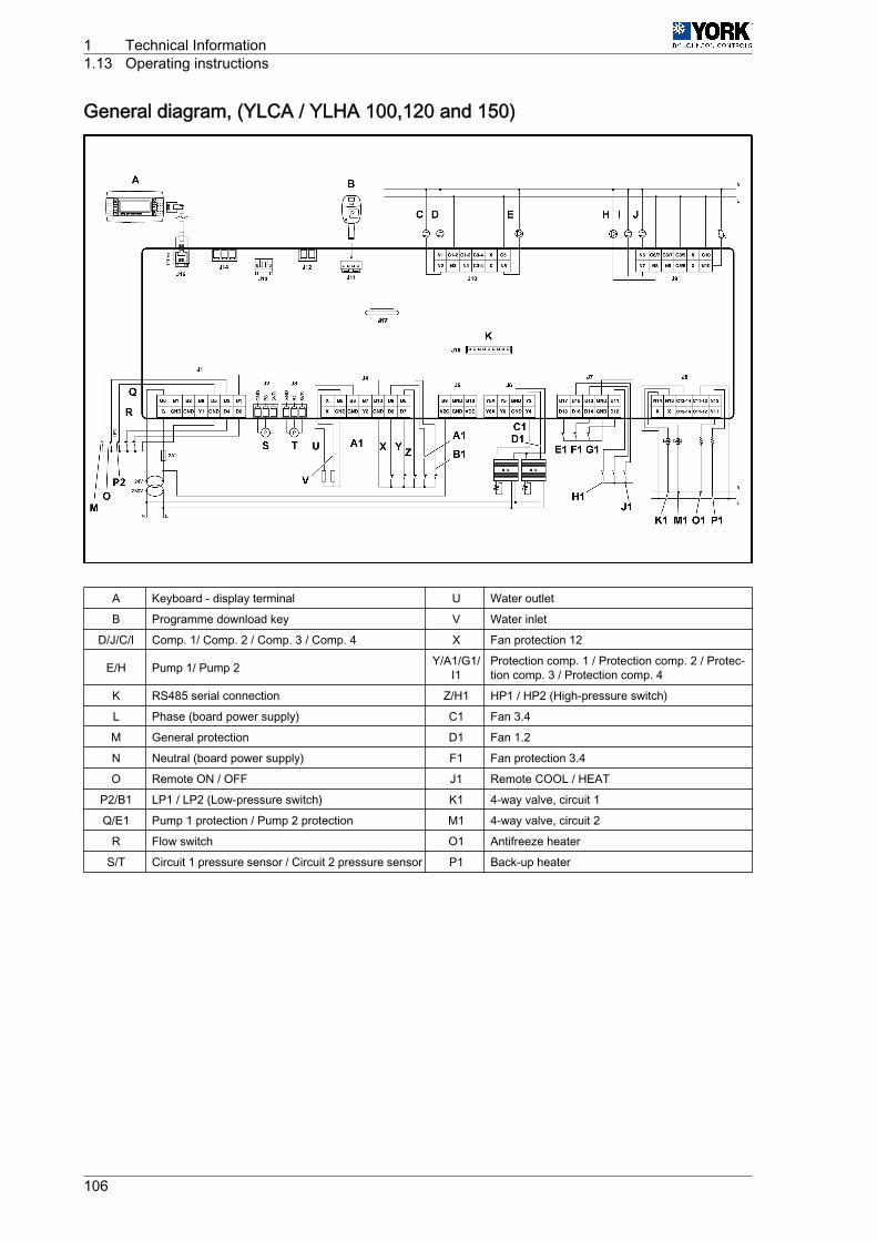
General diagram, (YLCA / YLHA 100,120 and 150)
A Keyboard ‑ display terminal U Water outlet
B Programme download key V Water inlet
D/J/C/I Comp. 1/ Comp. 2 / Comp. 3 / Comp. 4 X Fan protection 12
E/H Pump 1/ Pump 2 Y/A1/G1/I1
Protection comp. 1 / Protection comp. 2 / Protec‐tion comp. 3 / Protection comp. 4
K RS485 serial connection Z/H1 HP1 / HP2 (High-pressure switch)
L Phase (board power supply) C1 Fan 3.4
M General protection D1 Fan 1.2
N Neutral (board power supply) F1 Fan protection 3.4
O Remote ON / OFF J1 Remote COOL / HEAT
P2/B1 LP1 / LP2 (Low-pressure switch) K1 4-way valve, circuit 1
Q/E1 Pump 1 protection / Pump 2 protection M1 4-way valve, circuit 2
R Flow switch O1 Antifreeze heater
S/T Circuit 1 pressure sensor / Circuit 2 pressure sensor P1 Back-up heater
1 Technical Information1.13 Operating instructions
106
Start-upAbout 45 seconds after powering the unit, the start-up display is activated.
Default language: English.
1st Display. START-UP(information on water temperature/unit status)• Water inlet temperature• Water outlet temperature• Unit status (ON/OFF)
Press "down" to access the second display.
2nd Display. STATUS AND OPERATING MODE SELECTION
Status selection ON/OFF (with ENTER, Up and Down).
On the heat pump units, select the COOL/HEAT operating mode (with ENTER, Up and Down).
Press ESC to return to the 1st display.
SYSTEM CONFIGURATION
(For authorised servicing personnel only)
3rd Display. ENTER PASSWORDThe 3rd Enter password display is accessed by pressing Up from the 1st display (Start-up), or Downfrom the 2nd display (Status / operating mode selection)1 From the Enter password display, press ENTER.2 Enter the password using the Up key.3 Press ENTER to access the 4th Menu display.
4th Display. MENUFrom this display we can access a set of submenus that provide information on the unit or allow for itsoperating parameters to be configured. These submenus are as follows:
-/- Sensors Sensors config.-A- Antifreeze Antifreeze-B- Input/output Input/output-c- Compressors Comps. conf.-d- Defrost Defrost-F- Condensation (fans) Condensation-H- Unit configuration Unit config.-P- Alarms Alarm settings-r- Temperature control Control param.
-Fr- Software version / language selection Soft. version-t- Time (not available) Time config.
To enter a submenu:1 Select it using the Up or Down key and then activate it using the ENTER key2 Once the parameters are set with the ENTER, Up and Down keys, press Prg to confirm the modifi‐
cation and return to the MENU display.3 To exit the MENU display, press the Esc key.
Technical Information 1Operating instructions 1.13
107
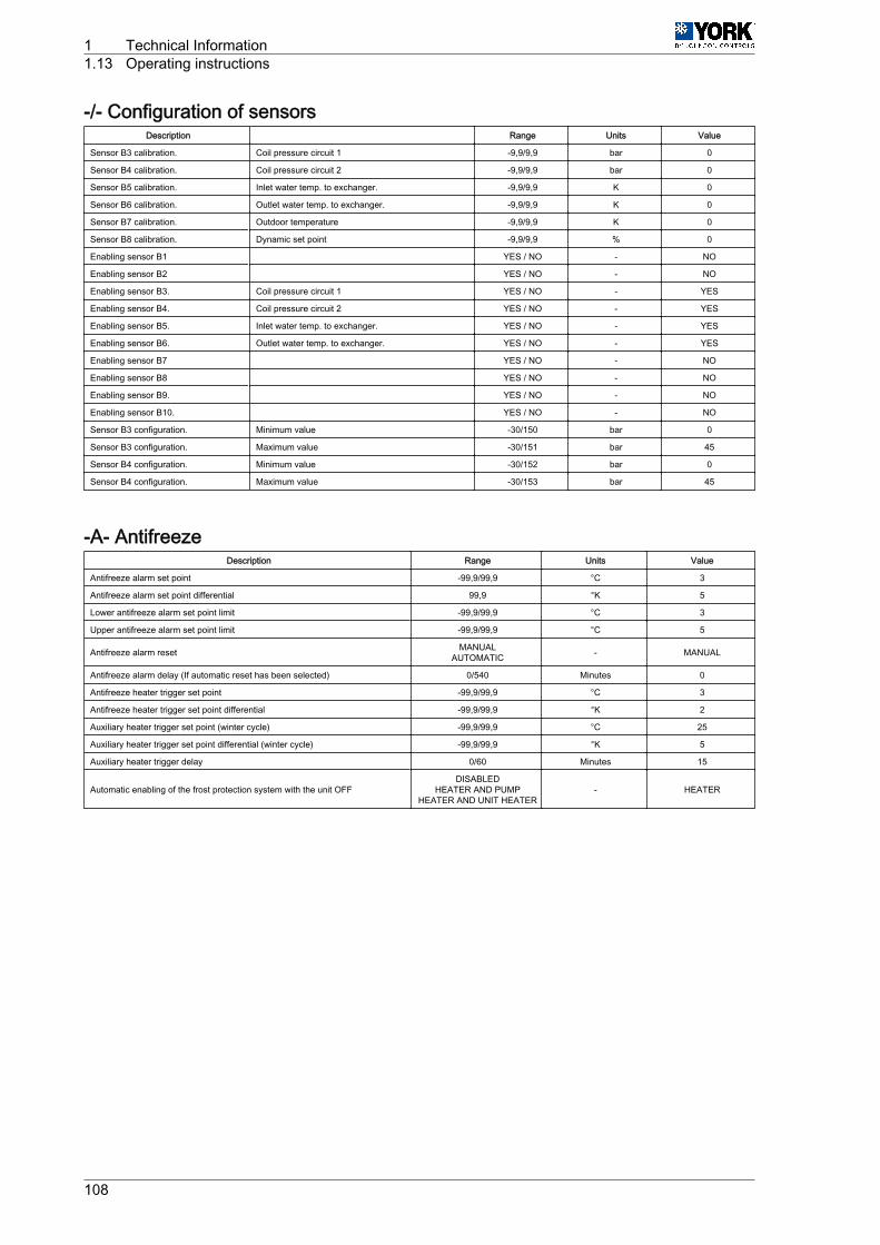
-/- Configuration of sensorsDescription Range Units Value
Sensor B3 calibration. Coil pressure circuit 1 -9,9/9,9 bar 0
Sensor B4 calibration. Coil pressure circuit 2 -9,9/9,9 bar 0
Sensor B5 calibration. Inlet water temp. to exchanger. -9,9/9,9 K 0
Sensor B6 calibration. Outlet water temp. to exchanger. -9,9/9,9 K 0
Sensor B7 calibration. Outdoor temperature -9,9/9,9 K 0
Sensor B8 calibration. Dynamic set point -9,9/9,9 % 0
Enabling sensor B1 YES / NO - NO
Enabling sensor B2 YES / NO - NO
Enabling sensor B3. Coil pressure circuit 1 YES / NO - YES
Enabling sensor B4. Coil pressure circuit 2 YES / NO - YES
Enabling sensor B5. Inlet water temp. to exchanger. YES / NO - YES
Enabling sensor B6. Outlet water temp. to exchanger. YES / NO - YES
Enabling sensor B7 YES / NO - NO
Enabling sensor B8 YES / NO - NO
Enabling sensor B9. YES / NO - NO
Enabling sensor B10. YES / NO - NO
Sensor B3 configuration. Minimum value -30/150 bar 0
Sensor B3 configuration. Maximum value -30/151 bar 45
Sensor B4 configuration. Minimum value -30/152 bar 0
Sensor B4 configuration. Maximum value -30/153 bar 45
-A- AntifreezeDescription Range Units Value
Antifreeze alarm set point -99,9/99,9 °C 3
Antifreeze alarm set point differential 99,9 °K 5
Lower antifreeze alarm set point limit -99,9/99,9 °C 3
Upper antifreeze alarm set point limit -99,9/99,9 °C 5
Antifreeze alarm reset MANUALAUTOMATIC - MANUAL
Antifreeze alarm delay (If automatic reset has been selected) 0/540 Minutes 0
Antifreeze heater trigger set point -99,9/99,9 °C 3
Antifreeze heater trigger set point differential -99,9/99,9 °K 2
Auxiliary heater trigger set point (winter cycle) -99,9/99,9 °C 25
Auxiliary heater trigger set point differential (winter cycle) -99,9/99,9 °K 5
Auxiliary heater trigger delay 0/60 Minutes 15
Automatic enabling of the frost protection system with the unit OFFDISABLED
HEATER AND PUMPHEATER AND UNIT HEATER
- HEATER
1 Technical Information1.13 Operating instructions
108
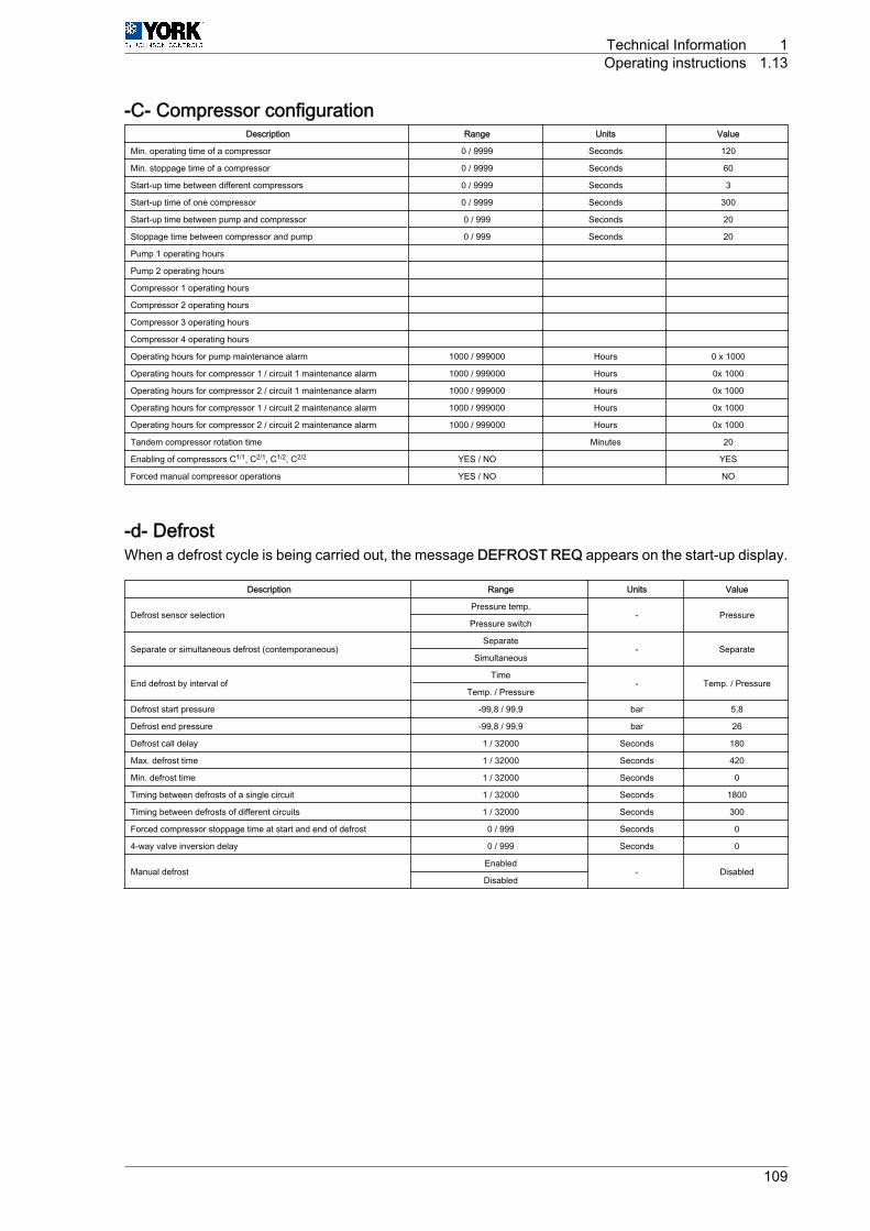
-C- Compressor configurationDescription Range Units Value
Min. operating time of a compressor 0 / 9999 Seconds 120
Min. stoppage time of a compressor 0 / 9999 Seconds 60
Start-up time between different compressors 0 / 9999 Seconds 3
Start-up time of one compressor 0 / 9999 Seconds 300
Start-up time between pump and compressor 0 / 999 Seconds 20
Stoppage time between compressor and pump 0 / 999 Seconds 20
Pump 1 operating hours
Pump 2 operating hours
Compressor 1 operating hours
Compressor 2 operating hours
Compressor 3 operating hours
Compressor 4 operating hours
Operating hours for pump maintenance alarm 1000 / 999000 Hours 0 x 1000
Operating hours for compressor 1 / circuit 1 maintenance alarm 1000 / 999000 Hours 0x 1000
Operating hours for compressor 2 / circuit 1 maintenance alarm 1000 / 999000 Hours 0x 1000
Operating hours for compressor 1 / circuit 2 maintenance alarm 1000 / 999000 Hours 0x 1000
Operating hours for compressor 2 / circuit 2 maintenance alarm 1000 / 999000 Hours 0x 1000
Tandem compressor rotation time Minutes 20
Enabling of compressors C1/1, C2/1, C1/2, C2/2 YES / NO YES
Forced manual compressor operations YES / NO NO
-d- DefrostWhen a defrost cycle is being carried out, the message DEFROST REQ appears on the start-up display.
Description Range Units Value
Defrost sensor selectionPressure temp.
- PressurePressure switch
Separate or simultaneous defrost (contemporaneous)Separate
- SeparateSimultaneous
End defrost by interval ofTime
- Temp. / PressureTemp. / Pressure
Defrost start pressure -99,8 / 99,9 bar 5,8
Defrost end pressure -99,8 / 99,9 bar 26
Defrost call delay 1 / 32000 Seconds 180
Max. defrost time 1 / 32000 Seconds 420
Min. defrost time 1 / 32000 Seconds 0
Timing between defrosts of a single circuit 1 / 32000 Seconds 1800
Timing between defrosts of different circuits 1 / 32000 Seconds 300
Forced compressor stoppage time at start and end of defrost 0 / 999 Seconds 0
4-way valve inversion delay 0 / 999 Seconds 0
Manual defrostEnabled
- DisabledDisabled
Technical Information 1Operating instructions 1.13
109
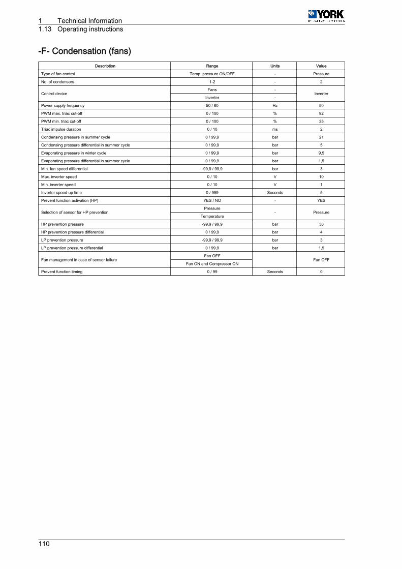
-F- Condensation (fans)Description Range Units Value
Type of fan control Temp. pressure ON/OFF - Pressure
No. of condensers 1-2 - 2
Control deviceFans -
InverterInverter -
Power supply frequency 50 / 60 Hz 50
PWM max. triac cut-off 0 / 100 % 92
PWM min. triac cut-off 0 / 100 % 35
Triac impulse duration 0 / 10 ms 2
Condensing pressure in summer cycle 0 / 99,9 bar 21
Condensing pressure differential in summer cycle 0 / 99,9 bar 5
Evaporating pressure in winter cycle 0 / 99,9 bar 9,5
Evaporating pressure differential in summer cycle 0 / 99,9 bar 1,5
Min. fan speed differential -99,9 / 99,9 bar 3
Max. inverter speed 0 / 10 V 10
Min. inverter speed 0 / 10 V 1
Inverter speed-up time 0 / 999 Seconds 5
Prevent function activation (HP) YES / NO - YES
Selection of sensor for HP preventionPressure
- PressureTemperature
HP prevention pressure -99,9 / 99,9 bar 38
HP prevention pressure differential 0 / 99,9 bar 4
LP prevention pressure -99,9 / 99,9 bar 3
LP prevention pressure differential 0 / 99,9 bar 1,5
Fan management in case of sensor failureFan OFF
Fan OFFFan ON and Compressor ON
Prevent function timing 0 / 99 Seconds 0
1 Technical Information1.13 Operating instructions
110
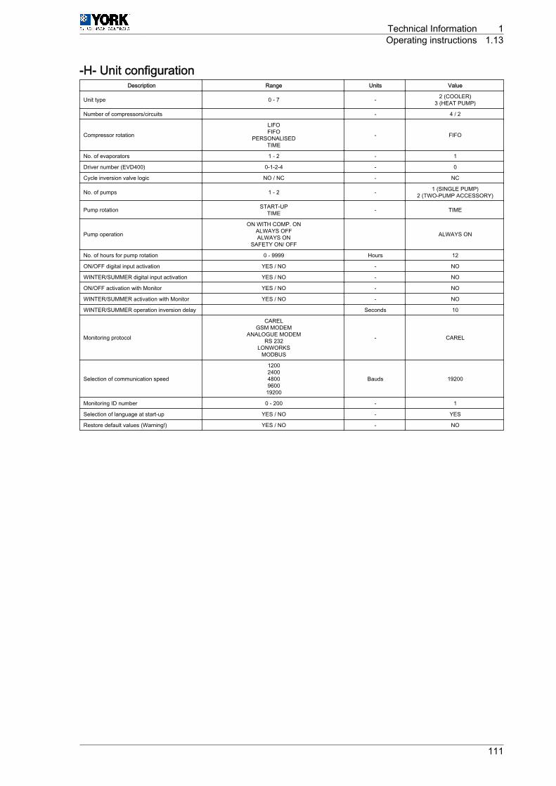
-H- Unit configurationDescription Range Units Value
Unit type 0 ‑ 7 - 2 (COOLER)3 (HEAT PUMP)
Number of compressors/circuits - 4 / 2
Compressor rotation
LIFOFIFO
PERSONALISEDTIME
- FIFO
No. of evaporators 1 ‑ 2 - 1
Driver number (EVD400) 0-1-2-4 - 0
Cycle inversion valve logic NO / NC - NC
No. of pumps 1 ‑ 2 - 1 (SINGLE PUMP)2 (TWO-PUMP ACCESSORY)
Pump rotation START-UPTIME - TIME
Pump operation
ON WITH COMP. ONALWAYS OFFALWAYS ON
SAFETY ON/ OFF
ALWAYS ON
No. of hours for pump rotation 0 ‑ 9999 Hours 12
ON/OFF digital input activation YES / NO - NO
WINTER/SUMMER digital input activation YES / NO - NO
ON/OFF activation with Monitor YES / NO - NO
WINTER/SUMMER activation with Monitor YES / NO - NO
WINTER/SUMMER operation inversion delay Seconds 10
Monitoring protocol
CARELGSM MODEM
ANALOGUE MODEMRS 232
LONWORKSMODBUS
- CAREL
Selection of communication speed
120024004800960019200
Bauds 19200
Monitoring ID number 0 ‑ 200 - 1
Selection of language at start-up YES / NO - YES
Restore default values (Warning!) YES / NO - NO
Technical Information 1Operating instructions 1.13
111
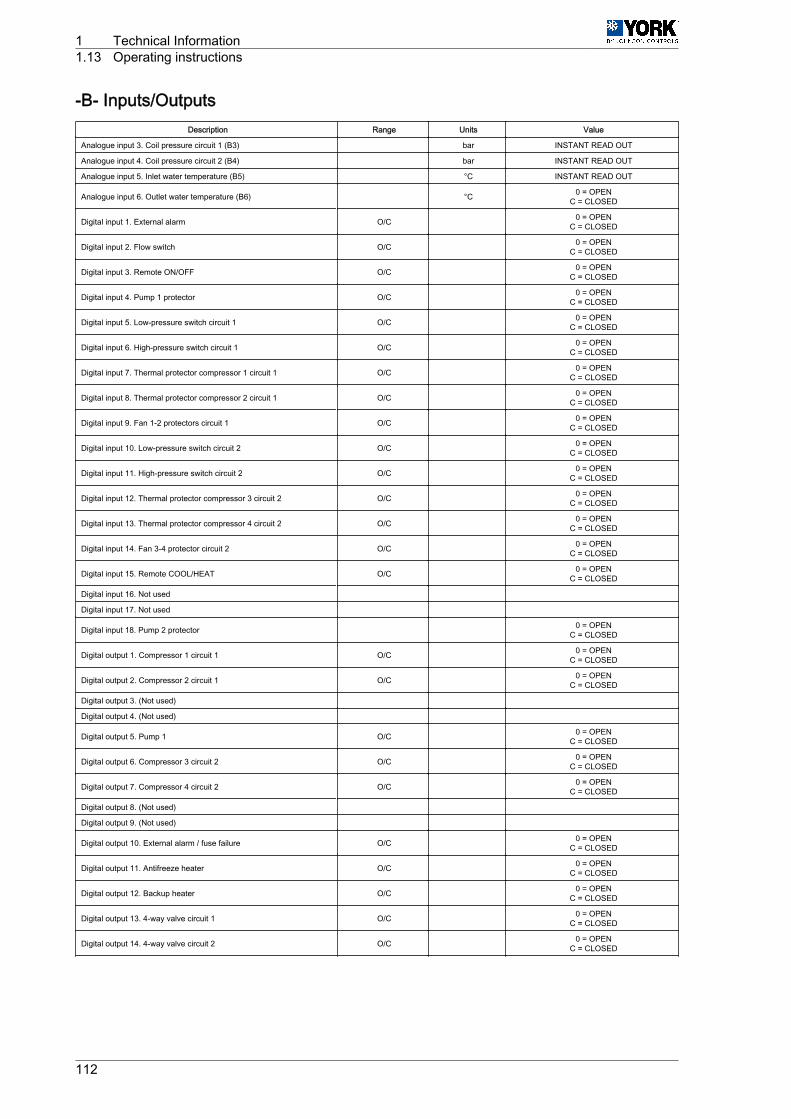
-B- Inputs/OutputsDescription Range Units Value
Analogue input 3. Coil pressure circuit 1 (B3) bar INSTANT READ OUT
Analogue input 4. Coil pressure circuit 2 (B4) bar INSTANT READ OUT
Analogue input 5. Inlet water temperature (B5) °C INSTANT READ OUT
Analogue input 6. Outlet water temperature (B6) °C 0 = OPENC = CLOSED
Digital input 1. External alarm O/C 0 = OPENC = CLOSED
Digital input 2. Flow switch O/C 0 = OPENC = CLOSED
Digital input 3. Remote ON/OFF O/C 0 = OPENC = CLOSED
Digital input 4. Pump 1 protector O/C 0 = OPENC = CLOSED
Digital input 5. Low-pressure switch circuit 1 O/C 0 = OPENC = CLOSED
Digital input 6. High-pressure switch circuit 1 O/C 0 = OPENC = CLOSED
Digital input 7. Thermal protector compressor 1 circuit 1 O/C 0 = OPENC = CLOSED
Digital input 8. Thermal protector compressor 2 circuit 1 O/C 0 = OPENC = CLOSED
Digital input 9. Fan 1-2 protectors circuit 1 O/C 0 = OPENC = CLOSED
Digital input 10. Low-pressure switch circuit 2 O/C 0 = OPENC = CLOSED
Digital input 11. High-pressure switch circuit 2 O/C 0 = OPENC = CLOSED
Digital input 12. Thermal protector compressor 3 circuit 2 O/C 0 = OPENC = CLOSED
Digital input 13. Thermal protector compressor 4 circuit 2 O/C 0 = OPENC = CLOSED
Digital input 14. Fan 3-4 protector circuit 2 O/C 0 = OPENC = CLOSED
Digital input 15. Remote COOL/HEAT O/C 0 = OPENC = CLOSED
Digital input 16. Not used
Digital input 17. Not used
Digital input 18. Pump 2 protector 0 = OPENC = CLOSED
Digital output 1. Compressor 1 circuit 1 O/C 0 = OPENC = CLOSED
Digital output 2. Compressor 2 circuit 1 O/C 0 = OPENC = CLOSED
Digital output 3. (Not used)
Digital output 4. (Not used)
Digital output 5. Pump 1 O/C 0 = OPENC = CLOSED
Digital output 6. Compressor 3 circuit 2 O/C 0 = OPENC = CLOSED
Digital output 7. Compressor 4 circuit 2 O/C 0 = OPENC = CLOSED
Digital output 8. (Not used)
Digital output 9. (Not used)
Digital output 10. External alarm / fuse failure O/C 0 = OPENC = CLOSED
Digital output 11. Antifreeze heater O/C 0 = OPENC = CLOSED
Digital output 12. Backup heater O/C 0 = OPENC = CLOSED
Digital output 13. 4-way valve circuit 1 O/C 0 = OPENC = CLOSED
Digital output 14. 4-way valve circuit 2 O/C 0 = OPENC = CLOSED
1 Technical Information1.13 Operating instructions
112

-P- AlarmsDescription Range Units Value
High-pressure alarm set point (transducer B3; B4) 0 / 99,9 bar 41
High-pressure alarm differential (transducer B3; B4) 0 / 99,9 bar 10
Summer low-pressure alarm 0 / 99,9 bar 3
Winter low-pressure alarm 0 / 99,9 bar 2
Defrost low-pressure alarm 0 / 99,9 bar 1
Low-pressure differential 0 / 99,9 bar 1
Low-pressure alarm delay on cold cycle start-up 0 ‑ 999 Seconds 60
Low-pressure alarm delay on heat cycle and defrost 0 ‑ 999 Seconds 0
Water flow control (flow switch) alarm delay on start-up 0 ‑ 999 Seconds 20
Water flow control (flow switch) alarm delay on operating 0 ‑ 9999 Seconds 5
Number of automatic reset alarm stoppages 0 ‑ 4 1
Maximum period for automatic reset alarms 0 ‑ 99 Minutes 60
Alarm selection with automatic reset: compressor thermal breaker AUTOMATIC/ MANUAL AUTOMATIC
Alarm selection with automatic reset: fan thermal breaker AUTOMATIC/ MANUAL AUTOMATIC
Alarm selection with automatic reset: low-pressure switch AUTOMATIC/ MANUAL AUTOMATIC
Alarm selection with automatic reset: high-pressure switch AUTOMATIC/ MANUAL AUTOMATIC
-r- ControlWhen this submenu is activated, the dynamic set point temperature appears (if this function is enabled).Press Down to access the configuration menu.
Description Range Units Value
Set point in COOL °C 12
Set point in HEAT °C 40
Temperature control adjustment range °K 3
COOL set point lower limit °C 6
COOL set point upper limit °C 20
HEAT set point lower limit °C 25
HEAT set point upper limit °C 45
Temperature setting type INPUT / OUTPUT - INPUT
Setting type with input sensor PROPORTIONAL / P+I PROPORTIONAL
Integration time in each adjustment P+I 0 / 9999 Seconds 600
Max. increase time of call (output adjustment) 0 / 9999 Seconds 20
Min. increase time of call (output adjustment) 0 / 9999 Seconds 20
Max. decrease time of call (output adjustment) 0 / 9999 Seconds 10
Min. decrease time of call (output adjustment) 0 / 9999 Seconds 10
Temp. differential in which increase and decrease times vary(output adjustment) -99,9 / 99,9 °C 2
Forced stoppage in COOL cycle (output adjustment) -99,9 / 99,9 °C 5
Forced stoppage in HEAT cycle (output adjustment) -99,9 / 99,9 °C 47
Technical Information 1Operating instructions 1.13
113
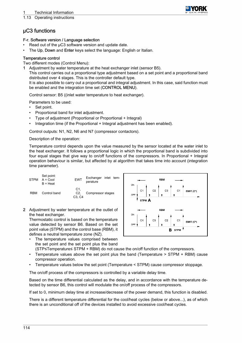
µC3 functionsF-r. Software version / Language selection• Read out of the µC3 software version and update date.• The Up, Down and Enter keys select the language: English or Italian.
Temperature controlTwo different modes (Control Menu):1 Adjustment by water temperature at the heat exchanger inlet (sensor B5).
This control carries out a proportional type adjustment based on a set point and a proportional banddistributed over 4 stages. This is the controller default type.It is also possible to carry out a proportional and integral adjustment. In this case, said function mustbe enabled and the integration time set (CONTROL MENU).
Control sensor: B5 ((inlet water temperature to heat exchanger).
Parameters to be used:• Set point.• Proportional band for inlet adjustment.• Type of adjustment (Proportional or Proportional + Integral)• Integration time (if the Proportional + Integral adjustment has been enabled).
Control outputs: N1, N2, N6 and N7 (compressor contactors).
Description of the operation:
Temperature control depends upon the value measured by the sensor located at the water inlet tothe heat exchanger. It follows a proportional logic in which the proportional band is subdivided intofour equal stages that give way to on/off functions of the compressors. In Proportional + Integraloperation behaviour is similar, but affected by al algorithm that takes time into account (integrationtime parameter).
STPMSet point:A = CoolB = Heat
EWT Exchanger inlet tem‐perature
RBM Control bandC1,C2,
C3, C4Compressor stages
2 Adjustment by water temperature at the outlet ofthe heat exchanger.Thermostatic control is based on the temperaturevalue detected by sensor B6. Based on the setpoint value (STPM) and the control base (RBM), itdefines a neutral temperature zone (NZ).• The temperature values comprised between
the set point and the set point plus the band(STP≤Temperature≤ STPM + RBM) do not cause the on/off function of the compressors.
• Temperature values above the set point plus the band (Temperature > STPM + RBM) causecompressor operation.
• Temperature values below the set point (Temperature < STPM) cause compressor stoppage.
The on/off process of the compressors is controlled by a variable delay time.
Based on the time differential calculated as the delay, and in accordance with the temperature de‐tected by sensor B6, this control will modulate the on/off process of the compressors.
If set to 0, minimum delay time at increase/decrease of the power demand, this function is disabled.
There is a different temperature differential for the cool/heat cycles (below or above...), as of whichthere is an unconditional off of the devices installed to avoid excessive cool/heat cycles.
1 Technical Information1.13 Operating instructions
114

STPM Set point TVD Phase input/output time
variation differential
RBM Control band HTON Stage activation maxi‐mum time delay
NZ Neutral zone LTON Stage activation mini‐mum time delay
EOWT
Water temperature atexchanger outlet
HTOFF
Stage deactivation max‐imum time delay
DonZ Compressor ONzone LT OFF Stage deactivation mini‐
mum time delayDoffZ Compressor off zone t Time
Compressor rotation
The controller provides a FIFO type rotation in which the first compressor to go on will also be the firstto go off.
Start-up sequence: C1, C2, C3, C4.
Stoppage sequence: C1, C2, C3, C4.
HP prevent
When this function is enabled, the controller attempts to avoid the blockage of the unit due to excessivelyhigh pressure. When said pressure reaches a preestablished value near the off pressure, the controllerspeeds up the fans to a maximum (if in cool cycle), or slows them down to a minimum (if in heat cycle).If the operating pressure continues getting close to the HP Prevent pressure, the controller turns off acompressor in the tandem of the affected circuit. The parameters of said function are accessed from theCONDENSATION menu.
Defrost cycle
If the evaporating pressure of one of the systems remains below the value set for starting defrost duringan accumulated period of time equal to the period established as the delay between defrosts, simulta‐neous defrost of all unit coils is started. The cycle ends once the pressure set as end defrost is reached,or at the end of the time period set as maximum duration of the cycle.
The defrost sequence is as follows:1 Compressor are turned off2 After 15 sec., the 4-way valves are inverted3 After 45 sec., the compressors start with the fans off4 Once defrost is completed, the compressors stop5 After 15 sec., the 4-way valves are inverted6 After 45 sec., the compressors and the fans start
Control sensors: Pressure transducers B3 and B4.
Parameters used:• Simultaneous defrost.• Defrost start pressure• Defrost end pressure• Defrost call delay• Max. defrost time• Min. defrost time• Forced compressor stoppage time due to cycle inversion• 4-way valve inversion delay
Affected outputs:• Compressors (N1, N2, N3 and N4)
Technical Information 1Operating instructions 1.13
115

• 4-way valves (N13 and N14)• Fans (Y3 and Y4)
DefrOff Defrost end pressure DefrAct Defrost activeDefrOn Defrost start pressure t Time
t 1...3Partial times remain‐ing in defrost startpressure zone
Antifreeze protection
If the B6 temperature sensor (water outlet) detects a temperature below the antifreeze set temperature,the unit is blocked and in a state of alarm (manual reset). Simultaneously, the protecting heaters of theplate heat exchanger (output N11) are connected. If the unit includes a hydro kit, the accumulator tankprotection heaters will also be activated.
Said heaters will turn off when the D6 sensor detects a temperature equal to the antifreeze temperature,plus a preestablished differential.
The antifreeze system will operate despite the status and mode of the unit.
Antifreeze protection can also include start-up of the pump and unit (see parameters in theANTI‐FREEZE menu).
Back-up heater
If following a preestablished time period after unit start-up in heat mode the water outlet temperaturedetected by B6 does not reach the minimum value, backup heater output (N12) is activated. Once thewater temperature has reached said value, plus a preestablished differential, said output will be deacti‐vated (see parameters in the ANTIFREEZE menu).
Remote ON/OFF
A digital ON/OFF remote input can be installed between terminals ID3-G0, and enabled with the corre‐sponding parameters of the H unit config menu.
If the contact is open, the unit will remain OFF. If the contact is closed, the unit will remain ON.
If the unit is OFF due to said digital input, a message appears on the display indicating as such.
The unit will remain OFF whenever any of its inputs: user keyboard, digital or monitoring input are OFF.
Remote COOL / HEAT
A digital COOL/HEAT remote input can be installed between terminals ID15-G0, and enabled with thecorresponding parameters of the H menu.
If the contact is open, the unit will remain in HEAT cycle. If the contact is closed, the unit will remain inCOOL cycle.
If the digital COOL/HEAT input is enabled, said selection cannot be made from the user's or supervisor'skeyboard.
To change the cycle, either from the digital input, the user's keyboard or the supervisor's keyboard, theunit must be OFF.
If the digital COOL/HEAT input is not enabled, said function can be carried out indifferently from theuser's or supervisor's keyboard.
1 Technical Information1.13 Operating instructions
116
Second pump
A second pump can be enabled by means of the -H-unit config menu. To do this, install the contactor(pump 230-1-50) between terminals N8-N, and the corresponding protector (contact NC) between ter‐minals Dl18-G0.
This second pump will operate alternately with the first pump, taking into account the number of operatinghours or start-up cycles. In the case of a protector failure of one of the two pumps, the available pumpwill activate immediately.
Download key
The central C3 module has a connector (J11) for connection of a download key (PSOPZKEYAO) withthe unit operational programme.
Serial connection for monitoring
Controller C3 allows connecting to a monitoring system using an RS485 serial board. It is possible toconfigure and enable this function from the -H- unit config menu. The system has two monitoring proto‐cols: Carel and Modbus.
AUTO-RESTART
When the unit is turned off by a power shortage, and once this has been restored, the unit retains thesame operating mode and status that was present before the shortage.
Alarm system
When an alarm is triggered, the red key on the upper left corner of the user's keyboard-display lights up.By pressing this key, the cause of the alarm appears on the display. Then press the Up or Down keysto check for further causes of the failure, which will appear on the display successively. When the alarmsare automatically reset, unit operations are restored once the causes of the alarm have disappeared. Ifthe failure is manually reset, and once its cause has disappeared, the Alarm key must be pressed torestore unit operations. The press the Esc button to return to the initial display.
Technical Information 1Operating instructions 1.13
117
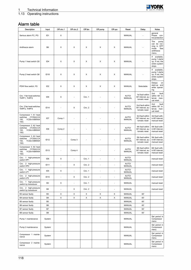
Alarm tableDescription Input Off circ.1 Off circ.2 Off fan Off pump Off sys Reset Delay Notes
Serious alarm FC, PG ID1 X MANUAL -generalPhase con‐trol protection
Antifreeze alarm B6 X X X X X MANUAL -
The pumpcan be run‐ning in OFFmode. Seeantifreezamenu.
Pump 1 heat switch Q5 ID4 X X X X X MANUAL -
If available,pump 1 startsup. If not, theentire systemstops.
Pump 2 heat switch Q6 ID18 X X X X X MANUAL -
If available,pump 1 startsup. If not, theentire systemstops.
PDW flow switch, FS ID2 X X X X X MANUAL Selectable
Delays onstart-up andwhile operat‐ing
Circ. 1 fan heat switchesTHPF1, THPF2 ID9 X - Circ. 1 - - AUTO/
MANUAL
1st fault within60' interval, au‐tomatic reset
2nd faultwithin 60' in‐terval, man‐ual reset
Circ. 2 fan heat switchesTHPF3, THPF4 ID14 - X Circ. 2 - - AUTO/
MANUAL
2nd fault within60' interval, au‐tomatic reset
2nd faultwithin 60' in‐terval, man‐ual reset
Compressor 1 A1 heatswitches (YCSA/LCA150, YCSA-H/BRAW150)
ID7 Comp 1 - - - - AUTO/MANUAL
3rd fault within60' interval, au‐tomatic reset
3rd fault with‐in 60' interval,manual reset
Compressor 2 A2 heatswitches (YCSA/LCA150, YCSA-H/BRAW150)
ID8 Comp 2 - - - - AUTO/MANUAL
4th fault within60' interval, au‐tomatic reset
4th fault with‐in 60' interval,manual reset
Compressor 3 A3 heatswitches (YCSA/LCA150, YCSA-H/BRAW150)
ID12 - Comp 3 - - - AUTO/MANUAL
5th fault within60' interval, au‐tomatic reset
5th fault with‐in 60' interval,manual reset
Compressor 4 A4 heatswitches (YCSA/LCA150, YCSA-H/BRAW150)
ID13 - Comp 4 - - - AUTO/MANUAL
6th fault within60' interval, au‐tomatic reset
6th fault with‐in 60' interval,manual reset
Circ. 1 high-pressureswitch HP1 ID6 X - Circ. 1 - - AUTO/
MANUAL manual reset
Circ. 2 high-pressureswitch HP2 ID11 - X Circ. 2 - - AUTO/
MANUAL manual reset
Circ. 1 high-pressureswitch LP1 ID5 X - Circ. 1 - - AUTO/
MANUAL manual reset
Circ. 2 high-pressureswitch LP2 ID10 - X Circ. 2 - - AUTO/
MANUAL manual reset
Circ. 1 high-pressureswitch by transducer B3 X - Circ. 1 - - MANUAL manual reset
Circ. 2 high-pressureswitch by transducer B4 - X Circ. 2 - - MANUAL manual reset
B3 sensor faulty B3 X X X X X MANUAL 60'
B4 sensor faulty B4 X X X X X MANUAL 60'
B5 sensor faulty B5 MANUAL 60'
B6 sensor faulty B6 MANUAL 60'
B7 sensor faulty B7 MANUAL 60'
B8 sensor faulty B8 MANUAL 60'
Pump 1 maintenance System MANUAL Set period inCompressormenu
Pump 2 maintenance System MANUAL Set period inCompressormenu
Compressor 1 mainte‐nance System MANUAL
Set period inCompressormenu
Compressor 2 mainte‐nance System MANUAL
Set period inCompressormenu
1 Technical Information1.13 Operating instructions
118

Description Input Off circ.1 Off circ.2 Off fan Off pump Off sys Reset Delay Notes
Compressor 3 mainte‐nance System MANUAL
Set period inCompressormenu
Compressor 4 mainte‐nance System MANUAL
Set period inCompressormenu
Technical Information 1Operating instructions 1.13
119

Temperature/resistance properties of NTC control sensors (10kOhms)Temperature
[°C]Resistance
[kOhms]Temperature
[°C]Resistance
[kOhms]Temperature
[°C]Resistance
[kOhms]Temperature
[°C]Resistance
[kOhms]Temperature
[°C]Resistance
[kOhms]
-50 329,2 -16 55,95 18 13,08 52 3,8 86 1,41
-49 310,7 -15 53,99 19 12,58 53 3,77 87 1,37
-48 293,3 -14 50,9 20 12,09 54 3,65 88 1,33
-47 277 -13 48,66 21 11,83 55 3,53 89 1,3
-46 261,8 -12 46,48 22 11,2 56 3,42 90 1,26
-45 247,5 -11 44,41 23 10,78 57 3,31 91 1,23
-44 234,1 -10 42,45 24 10,38 58 3,21 92 1,2
-43 221,8 -9 40,56 25 10 59 3,11 93 1,16
-42 209,8 -8 38,76 26 9,63 60 3,02 94 1,13
-41 198,7 -7 37,05 27 9,28 61 2,92 95 1,1
-40 188,4 -6 35,48 28 8,94 62 2,83 96 1,06
-39 178,3 -5 33,89 29 8,82 63 2,75 97 1,05
-38 168,9 -4 32,43 30 8,31 64 2,66 98 1,02
-37 160,1 -3 31,04 31 6,01 65 2,58 99 0,99
-36 151,8 -2 29,72 32 7,72 66 2,51 100 0,97
-35 144 -1 28,47 33 7,45 67 2,43 101 0,94
-34 136,6 0 27,28 34 7,19 68 2,36 102 0,92
-33 129,7 1 26,13 35 6,94 69 2,29 103 0,9
-32 123,2 2 25,03 36 6,69 70 2,22 104 0,87
-31 117,1 3 23,09 37 6,46 71 2,16 105 0,85
-30 111,3 4 22,09 38 6,24 72 2,1 106 0,83
-29 106,7 5 22,05 39 6,03 73 2,04 107 0,81
-28 100,4 6 21,15 40 5,82 74 1,98 108 0,79
-27 95,47 7 20,2 41 5,63 75 1,92 109 0,77
-26 90,8 8 19,48 42 5,43 76 1,87
-25 86,39 9 18,7 43 5,24 77 1,81
-24 82,22 10 17,98 44 5,08 78 1,76
-23 78,29 11 17,24 45 4,91 79 1,71
-22 74,58 12 16,55 46 4,74 80 1,66
-21 71,07 13 15,9 47 4,59 81 1,62
-20 67,74 14 15,28 48 4,44 82 1,57
-19 64,54 15 14,68 49 4,3 83 1,53
-18 61,62 16 14,12 50 4,16 84 1,49
-17 58,66 17 13,57 51 4,02 85 1,45
1 Technical Information1.13 Operating instructions
120
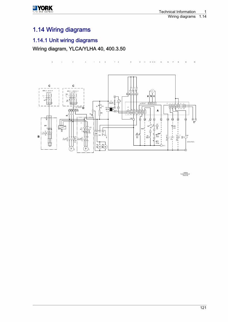
1.14 Wiring diagrams1.14.1 Unit wiring diagramsWiring diagram, YLCA/YLHA 40, 400.3.50
Technical Information 1Wiring diagrams 1.14
121
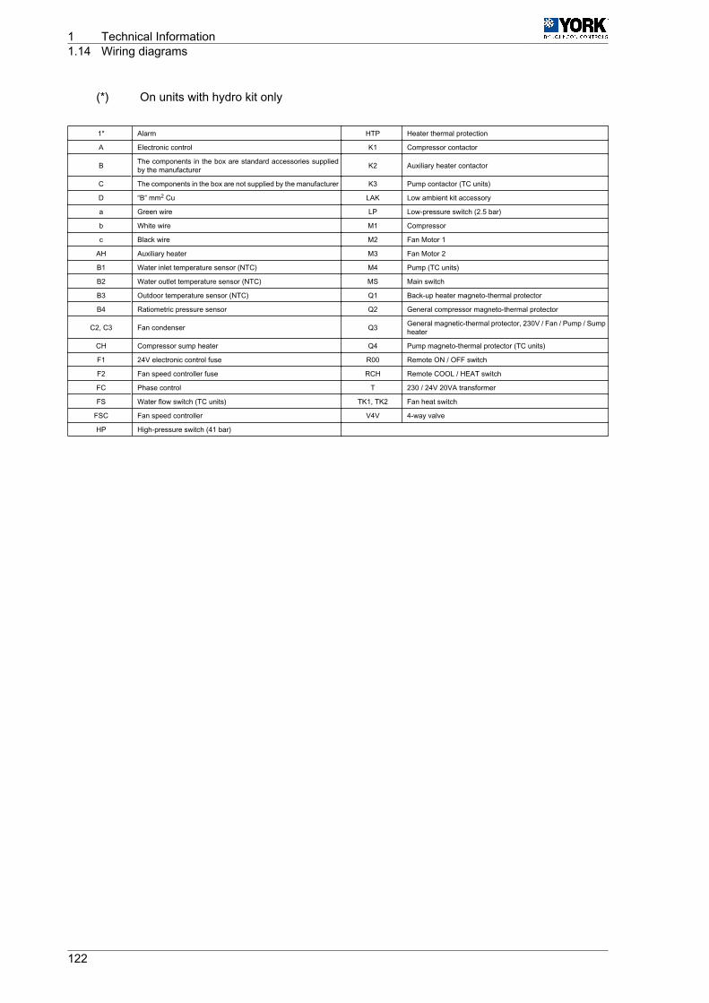
(*) On units with hydro kit only
1* Alarm HTP Heater thermal protection
A Electronic control K1 Compressor contactor
B The components in the box are standard accessories suppliedby the manufacturer K2 Auxiliary heater contactor
C The components in the box are not supplied by the manufacturer K3 Pump contactor (TC units)
D “B” mm2 Cu LAK Low ambient kit accessory
a Green wire LP Low-pressure switch (2.5 bar)
b White wire M1 Compressor
c Black wire M2 Fan Motor 1
AH Auxiliary heater M3 Fan Motor 2
B1 Water inlet temperature sensor (NTC) M4 Pump (TC units)
B2 Water outlet temperature sensor (NTC) MS Main switch
B3 Outdoor temperature sensor (NTC) Q1 Back-up heater magneto-thermal protector
B4 Ratiometric pressure sensor Q2 General compressor magneto-thermal protector
C2, C3 Fan condenser Q3 General magnetic-thermal protector, 230V / Fan / Pump / Sumpheater
CH Compressor sump heater Q4 Pump magneto-thermal protector (TC units)
F1 24V electronic control fuse R00 Remote ON / OFF switch
F2 Fan speed controller fuse RCH Remote COOL / HEAT switch
FC Phase control T 230 / 24V 20VA transformer
FS Water flow switch (TC units) TK1, TK2 Fan heat switch
FSC Fan speed controller V4V 4-way valve
HP High-pressure switch (41 bar)
1 Technical Information1.14 Wiring diagrams
122

Wiring diagrams YLCA 50, 60 and 80 (µC2), 400.3.50
YLCA Q5 D
50 63 3 x 25 + GND, N
60 80A 3 x 25 + GND, N
80 100A 3 x 35 + GND, N
Technical Information 1Wiring diagrams 1.14
123
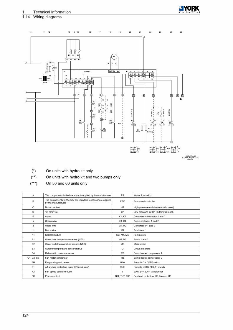
(*) On units with hydro kit only(**) On units with hydro kit and two pumps only(***) On 50 and 60 units only
A The components in the box are not supplied by the manufacturer FS Water flow switch
B The components in the box are standard accessories suppliedby the manufacturer FSC Fan speed controller
C Motor position HP High-pressure switch (automatic reset)
D “B” mm2 Cu LP Low-pressure switch (automatic reset)
E Alarm K1, K2 Compressor contactor 1 and 2
a Green wire K3, K4 Pump contactor 1 and 2
b White wire M1, M2 Compressor 1 and 2
c Black wire M2 Fan Motor 1
A1 Control module M3, M4, M5 Fan motors
B1 Water inlet temperature sensor (NTC) M6, M7 Pump 1 and 2
B2 Water outlet temperature sensor (NTC) MS Main switch
B3 Outdoor temperature sensor (NTC) Q Circuit breakers
B4 Ratiometric pressure sensor R7 Sump heater compressor 1
C1, C2, C3 Fan motor condenser R8 Sump heater compressor 2
EH Evaporating unit heater R00 Remote ON / OFF switch
F1 A1 and A2 protecting fuses (315 mA slow) RCH Remote COOL / HEAT switch
F2 Fan speed controller fuse T 230 / 24V 20VA transformer
FC Phase control TK1, TK2, TK3 Fan heat protectors M3, M4 and M5
1 Technical Information1.14 Wiring diagrams
124
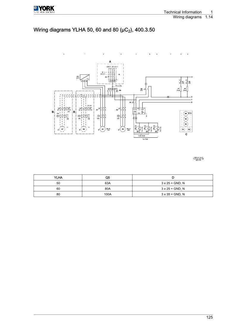
Wiring diagrams YLHA 50, 60 and 80 (µC2), 400.3.50
YLHA Q5 D
50 63A 3 x 25 + GND, N
60 80A 3 x 25 + GND, N
80 100A 3 x 35 + GND, N
Technical Information 1Wiring diagrams 1.14
125
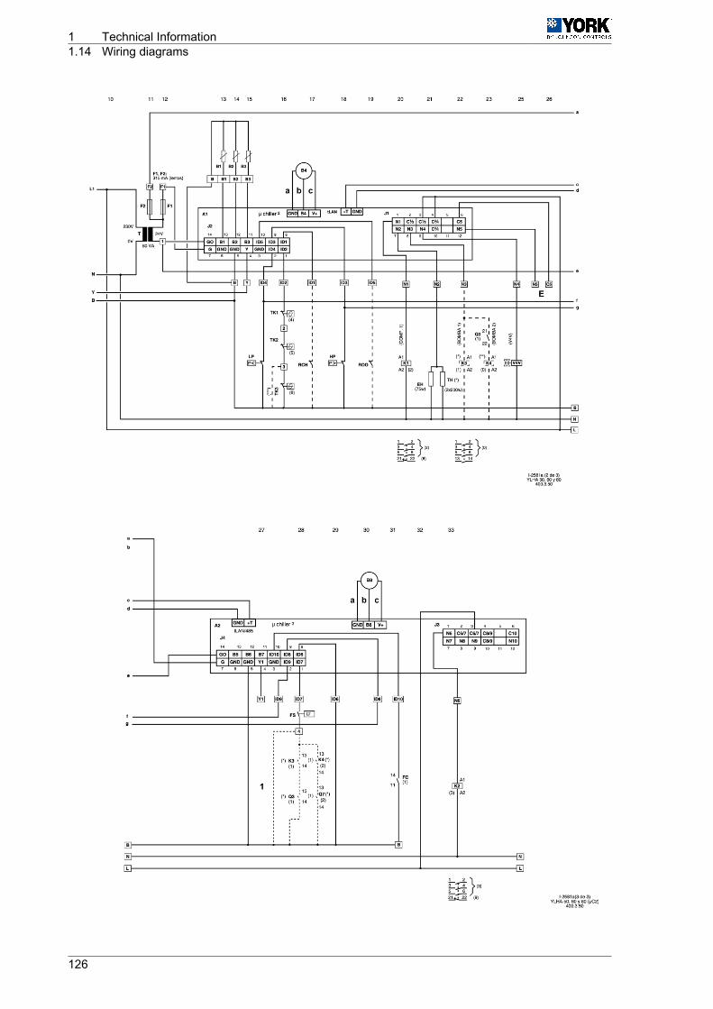
1 Technical Information1.14 Wiring diagrams
126
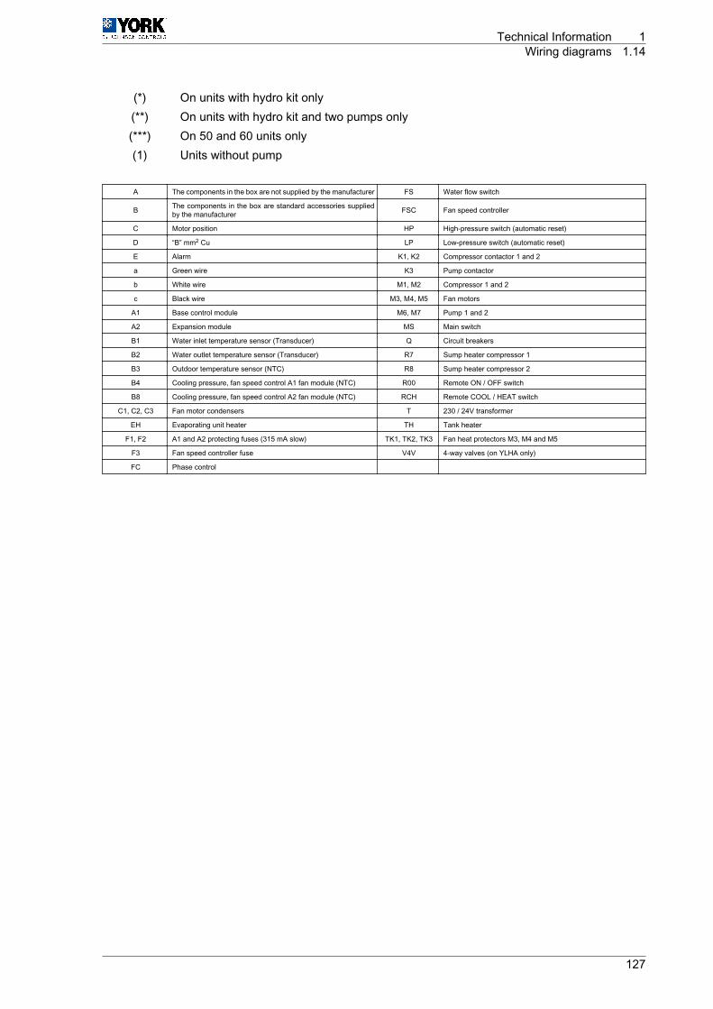
(*) On units with hydro kit only(**) On units with hydro kit and two pumps only(***) On 50 and 60 units only(1) Units without pump
A The components in the box are not supplied by the manufacturer FS Water flow switch
B The components in the box are standard accessories suppliedby the manufacturer FSC Fan speed controller
C Motor position HP High-pressure switch (automatic reset)
D “B” mm2 Cu LP Low-pressure switch (automatic reset)
E Alarm K1, K2 Compressor contactor 1 and 2
a Green wire K3 Pump contactor
b White wire M1, M2 Compressor 1 and 2
c Black wire M3, M4, M5 Fan motors
A1 Base control module M6, M7 Pump 1 and 2
A2 Expansion module MS Main switch
B1 Water inlet temperature sensor (Transducer) Q Circuit breakers
B2 Water outlet temperature sensor (Transducer) R7 Sump heater compressor 1
B3 Outdoor temperature sensor (NTC) R8 Sump heater compressor 2
B4 Cooling pressure, fan speed control A1 fan module (NTC) R00 Remote ON / OFF switch
B8 Cooling pressure, fan speed control A2 fan module (NTC) RCH Remote COOL / HEAT switch
C1, C2, C3 Fan motor condensers T 230 / 24V transformer
EH Evaporating unit heater TH Tank heater
F1, F2 A1 and A2 protecting fuses (315 mA slow) TK1, TK2, TK3 Fan heat protectors M3, M4 and M5
F3 Fan speed controller fuse V4V 4-way valves (on YLHA only)
FC Phase control
Technical Information 1Wiring diagrams 1.14
127
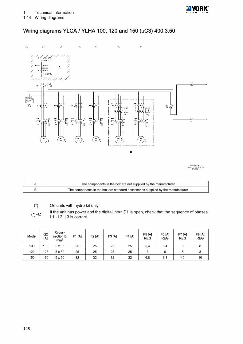
Wiring diagrams YLCA / YLHA 100, 120 and 150 (µC3) 400.3.50
A The components in the box are not supplied by the manufacturer
B The components in the box are standard accessories supplied by the manufacturer
(*) On units with hydro kit only
(*)FC If the unit has power and the digital input D1 is open, check that the sequence of phasesL1, L2, L3 is correct
Model Q2[A]
Cross-section B
mm2F1 [A] F2 [A] F3 [A] F4 [A] F5 [A]
REGF6 [A]REG
F7 [A]REG
F8 [A]REG
100 100 5 x 35 25 25 25 25 5,4 5,4 8 8
120 125 5 x 50 25 25 25 25 6 6 8 8
150 160 5 x 50 32 32 32 32 6,8 6,8 10 10
1 Technical Information1.14 Wiring diagrams
128
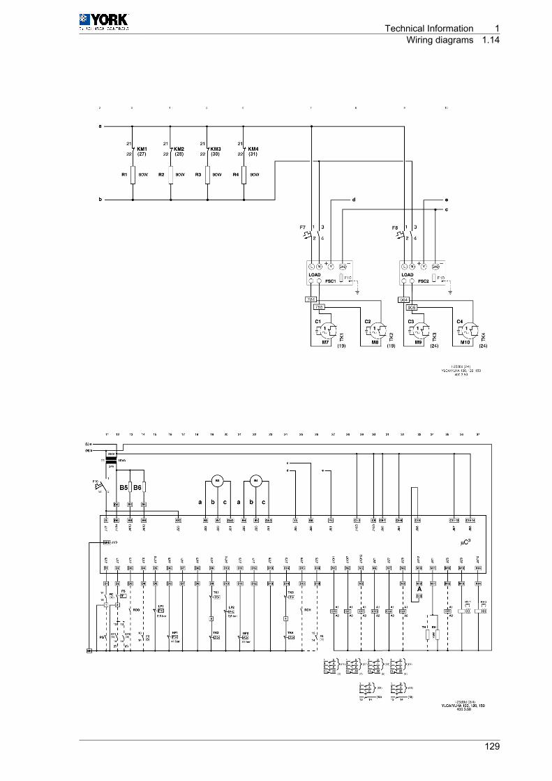
Technical Information 1Wiring diagrams 1.14
129
(**) Pm YLHAunits only N10 ‑ C10 = Voltage-free contact (-A- general protection alarm)
a White c Green
b Black
1 Technical Information1.14 Wiring diagrams
130
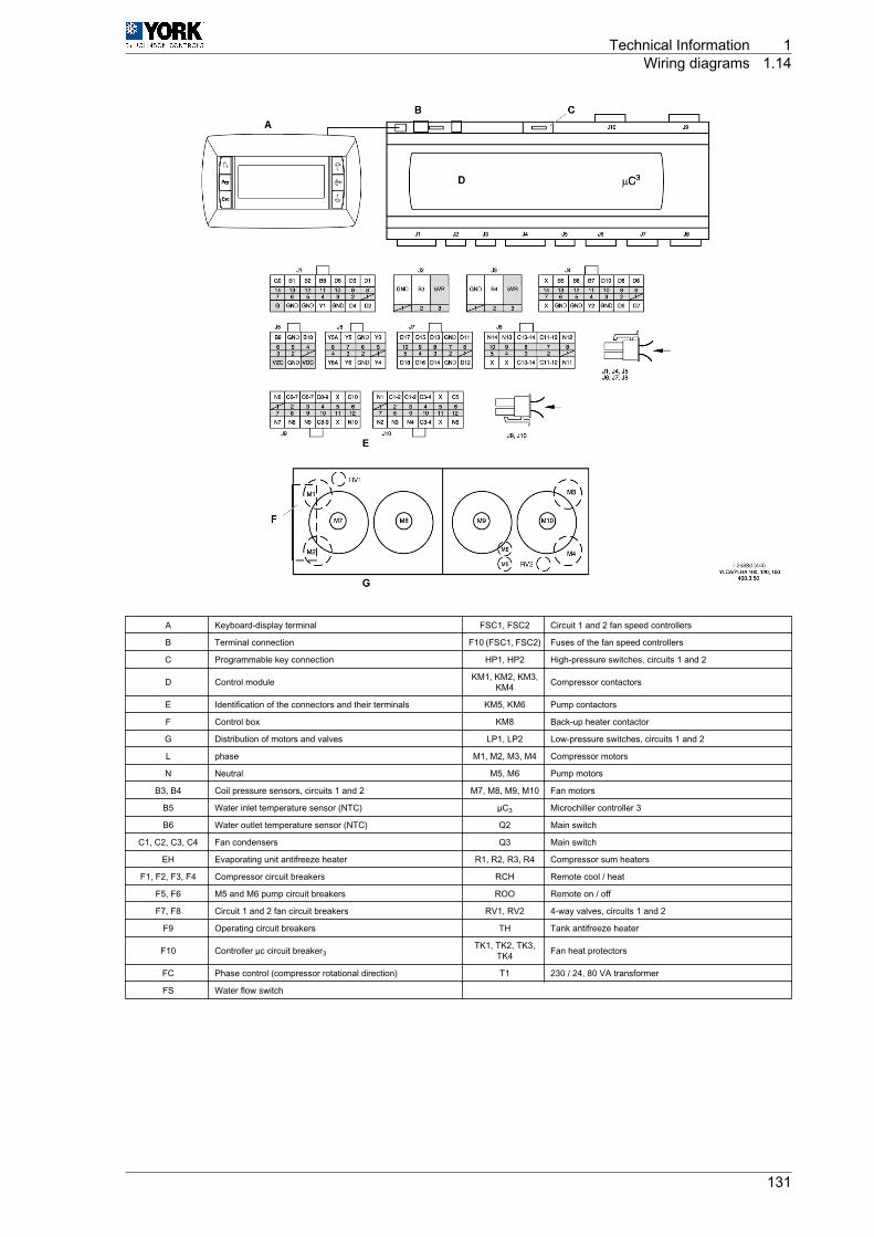
A Keyboard-display terminal FSC1, FSC2 Circuit 1 and 2 fan speed controllers
B Terminal connection F10 (FSC1, FSC2) Fuses of the fan speed controllers
C Programmable key connection HP1, HP2 High-pressure switches, circuits 1 and 2
D Control module KM1, KM2, KM3,KM4 Compressor contactors
E Identification of the connectors and their terminals KM5, KM6 Pump contactors
F Control box KM8 Back-up heater contactor
G Distribution of motors and valves LP1, LP2 Low-pressure switches, circuits 1 and 2
L phase M1, M2, M3, M4 Compressor motors
N Neutral M5, M6 Pump motors
B3, B4 Coil pressure sensors, circuits 1 and 2 M7, M8, M9, M10 Fan motors
B5 Water inlet temperature sensor (NTC) µC3 Microchiller controller 3
B6 Water outlet temperature sensor (NTC) Q2 Main switch
C1, C2, C3, C4 Fan condensers Q3 Main switch
EH Evaporating unit antifreeze heater R1, R2, R3, R4 Compressor sum heaters
F1, F2, F3, F4 Compressor circuit breakers RCH Remote cool / heat
F5, F6 M5 and M6 pump circuit breakers ROO Remote on / off
F7, F8 Circuit 1 and 2 fan circuit breakers RV1, RV2 4-way valves, circuits 1 and 2
F9 Operating circuit breakers TH Tank antifreeze heater
F10 Controller µc circuit breaker3TK1, TK2, TK3,
TK4 Fan heat protectors
FC Phase control (compressor rotational direction) T1 230 / 24, 80 VA transformer
FS Water flow switch
Technical Information 1Wiring diagrams 1.14
131