Embed Size (px)
Citation preview
AIRCRAFT ACCIDENT REPORT 1/2008
Air Accidents Investigation Branch
Department for Transport
Report on the serious incident toBombardier CL600-2B16 Challenger 604, VP-BJM
8 nm west of Midhurst VOR, West Sussex11 November 2005
This investigation was carried out in accordance withThe Civil Aviation (Investigation of Air Accidents and Incidents) Regulations 1996
ii
Printed in the United Kingdom for the Air Accidents Investigation Branch
© Crown Copyright 2008
Published with the permission of the Department for Transport (Air Accidents Investigation Branch).
This report contains facts which have been determined up to the time of publication. This information is published to inform the aviation industry and the public of the general circumstances of accidents and serious incidents.
Extracts can be published without specific permission providing that the source is duly acknowledged.
Published 10 January 2008
iii
RECENT FORMAL AIRCRAFT ACCIDENT AND INCIDENT REPORTSISSUED BY THE AIR ACCIDENTS INVESTIGATION BRANCH
THE FOLLOWING REPORTS ARE AVAILABLE ON THE INTERNET AThttp://www.aaib.gov.uk
2/2006 Pilatus Britten-Norman BN2B-26 Islander, G-BOMG November 2006 West-north-west of Campbeltown Airport, Scotland on 15 March 2005.
3/2006 Boeing 737-86N, G-XLAG December 2006 at Manchester Airport on 16 July 2003.
1/2007 British Aerospace ATP, G-JEMC January 2007 10 nm southeast of Isle of Man (Ronaldsway) Airport on 23 May 2005.
2/2007 Boeing 777-236, G-YMME March 2007 on departure from London Heathrow Airport on 10 June 2004.
3/2007 Piper PA-23-250 Aztec, N444DA May 2007 1 nm north of South Caicos Islands, Caribbean on 26 December 2005.
4/2007 Airbus A340-642, G-VATL September 2007 en-route from Hong Kong to London Heathrow on 8 February 2005.
5/2007 Airbus A321-231, G-MEDG December 2007 during an approach to Khartoum Airport, Sudan on 11 March 2005.
6/2007 Airbus A320-211, JY-JAR December 2007 at Leeds Bradford Airport on 18 May 2005.
7/2007 Airbus A310-304, F-OJHI December 2007 on approach to Birmingham International Airport on 23 February 2006.
iv
Department for TransportAir Accidents Investigation BranchFarnborough HouseBerkshire Copse RoadAldershotHampshire GU11 2HH
December 2007
The Right Honourable Ruth KellySecretary of State for Transport
Dear Secretary of State
I have the honour to submit the report by Mr R D G Carter, an Inspector of Air Accidents, on the circumstances of the serious incident to Bombardier CL600-2B16 Challenger 604, registration VP-BJM, 8 nm west of Midhurst VOR, West Sussex on 11 November 2005.
Yours sincerely
David KingChief Inspector of Air Accidents
v
Contents
Synopsis ............................................................................................................................ 1
1. Factual Information .............................................................................................. 3
1.1 History of the flight ....................................................................................... 3
1.2 Injuries to persons .......................................................................................... 5
1.3 Damage to aircraft .......................................................................................... 5
1.4 Other damage ................................................................................................. 5
1.5 Personnel information .................................................................................... 51.5.1 Commander ...................................................................................... 51.5.2 First Officer ...................................................................................... 5
1.6 Aircraft information ....................................................................................... 51.6.1 General information ......................................................................... 51.6.2 Aircraft description .......................................................................... 6
1.6.2.1 General .......................................................................... 61.6.3 Flight controls - pitch ...................................................................... 6
1.6.3.1 Flight controls - horizontal stabiliser pitch trim ........... 61.6.3.2 Flight controls - manual pitch trim ............................... 81.6.3.3 Flight controls - automatic pitch trim ........................... 91.6.3.4 Flight controls - Horizontal Stabiliser Trim Control Unit (HSTCU) ................................................. 9
1.6.4 Instrumentation .............................................................................. 10
1.7 Meteorological information ......................................................................... 11
1.8 Aids to navigation ........................................................................................ 11
1.9 Communications .......................................................................................... 11
1.10 Aerodrome information ................................................................................ 111.10.1 Airfields discussed with ATC ......................................................... 111.10.2 Other airfields in the South East of England .................................. 12
1.11 Flight Recorders .......................................................................................... 131.11.1 Cockpit Voice Recorder (CVR) ..................................................... 131.11.2 Flight Data Recorder (FDR) .......................................................... 13
1.11.2.1 Incident flight (11 November 2005) - FDR record ..... 131.11.2.2 Previous events on VP-BJM ...................................... 15
vi
1.12 Aircraft examination .................................................................................... 161.12.1 Initial examination (VP-BJM on 11 November 2005)................... 161.12.2 Detailed examination ..................................................................... 18
1.13 Medical and pathological information ......................................................... 20
1.14 Fire ............................................................................................................... 20
1.15 Survival aspects............................................................................................ 20
1.16 Tests and research ........................................................................................ 20
1.17 Organisational and management information .............................................. 20
1.18 Additional information ................................................................................. 211.18.1 Previous pitch trim events - VP-BJM ............................................ 211.18.2 Similar contamination findings ...................................................... 221.18.3 Previous actions taken ................................................................... 221.18.4 Certification regulations relating to pitch trim ............................... 221.18.5 Previous Recommendations ........................................................... 231.18.6 Aircraft landing performance with flap ......................................... 251.18.7 QRH procedures for STAB TRIM Msg ........................................... 261.18.8 Simulation of out-of-trim forces .................................................... 291.18.9 Safety action by manufacturer - AW604-27-0074 ......................... 29
2 Analysis ................................................................................................................. 31
2.1 Technical failures ......................................................................................... 312.1.1 Failure of the HSTCU .................................................................... 312.1.2 Cause of failure ............................................................................. 332.1.3 Action taken since Recommendation 2005-147 ............................ 342.1.4 Regulations and aircraft design ...................................................... 35
2.2 Crew actions ................................................................................................. 362.2.1 Flap selection following stabiliser trim failure .............................. 362.2.2 Simulation of out-of-trim forces .................................................... 372.2.3 Flight over densely populated areas by aircraft in an emergency .. 37
3. Conclusions .......................................................................................................... 40
(a) Findings ........................................................................................................ 40
(b) Causal factors ............................................................................................... 41
4 Safety Recommendations .................................................................................... 42
5 Safety actions taken ............................................................................................. 43
5.1 Safety action by manufacturer and regulators .............................................. 43
vii
GLOSSARY OF ABBREVIATIONS USED IN THIS REPORT
AAIB Air Accidents Investigation BranchAC Advisory CircularACJ Advisory Circular JointAD Airworthiness DirectiveAMC Acceptable Means of ComplianceAMJ Acceptable Means JointAP AutopilotATC Air Traffic ControlAW Advisory WireBITE Built In Test Equipment CAA Civil Aviation AuthorityCAP CAA PublicationCB Circuit BreakerCG Centre of GravityCH 1 Channel 1CH 2 Channel 2CS Certification SpecificationsCVR Cockpit Voice RecorderDC Direct CurrentDCU Display Control UnitEASA European Aviation Safety AgencyEFIS Electronic Flight Instrument
System EICAS Engine Indication and Crew
Alerting SystemFAA Federal Aviation AdministrationFAR Federal Aviation RegulationFCC Flight Control ComputerFDR Flight Data Recorder FL Flight Levelft feetGND Groundhrs hoursHSTA Horizontal Stabiliser Trim ActuatorHSTCU Horizontal Stabiliser Trim Control
UnitICAO International Civil Aviation
Organization ILS Instrument Landing SystemJAA Joint Aviation AuthoritiesJAR Joint Airworthiness Requirementkg kilogram(s)km kilometre(s)kt knot(s)
lb pound(s)lbf pounds forceLDA Landing Distance AvailableLDR Landing Distance RequiredLTCC London Terminal Control Centrem metresMATS Manual of Air Traffic ServicesMCQFS Manual of Criteria for the
Qualification of Flight SimulatorsMCU Motor Control UnitMsg Messagenm nautical mile(s)NTSB National Tranportation Safety
BoardNVM non-volatile memoryPCB Printed Circuit BoardPWR PowerQRH Quick Reference HandbookSIL Service Information LeafletUTC Coordinated Universal TimeVHF Very High FrequencyVOR VHF omnidirectional radio range°C degrees centigrade°M degrees magnetic

1
Air Accidents Investigation Branch
Aircraft Accident Report No: 1/2008 (EW/C2005/11/05)
Registered Owner and Operator Southern Air - Nigeria
Aircraft Type and Model Bombardier CL600-2B16 Challenger 604
Nationality Bermuda register
Registration VP-BJM
Location 8 nm west of Midhurst VOR, West Sussex
Date and Time 11 November 2005 at 1522 hrs Dates and times in this report are UTC unless otherwise stated
Synopsis
This serious incident was notified to the Air Accidents Investigation Branch (AAIB) by the London Terminal Control Centre (LTCC) on 11 November 2005, the day of the occurrence, and the investigation began that day. The following Inspectors participated in the investigation:
Mr R D G Carter Investigator-in-charge Mr P Sleight EngineeringMr J Firth OperationsMr J R James Flight Recorders
About four and half hours into a flight from Lagos, Nigeria, the autopilot pitch trim failed and subsequently the stabiliser trim system failed. Attempts were made to re-engage the stabiliser trim channels, resulting in channel 2 appearing to engage with no response to trim commands, and channel 1 engaging intermittently. During the flight the stabiliser occasionally trimmed nose down, despite applications of nose-up trim commands. The trim eventually reached almost full nose down. To counteract this, both flight crew members had to apply prolonged aft pressure on the control column. The aircraft diverted to London Heathrow for a landing with flap retracted, although the QRH required 20° flap following a stabiliser trim failure. The commander made the decision as the crew considered that applying flap would substantially increase the control column load required to maintain level flight.
2
Subsequent investigation found contamination, formed by electro-migration in the presence of moisture, within the Horizontal Stabiliser Trim Control Unit (HSTCU). The moisture was probably created by humid air condensing on the cooling motherboard during prolonged flight at altitude.
The investigation identified the following causal factors:
1. In the absence of a mechanical backup system or sufficient physical separation of the control channels, there was insufficient protection within the design of the HSTCU against the effects of environmental contamination.
2. The airworthiness requirements relating to the design and installation of electronic components did not sufficiently address the specific effects of fluid and moisture contamination as a source of common cause failures.
One Safety Recommendation is made in this report and one was made earlier in the investigation.
3
1. Factual Information
1.1 Historyoftheflight
The aircraft departed Lagos Airport, Nigeria at 0937 hrs to fly to Farnborough in the United Kingdom. The crew comprised the two pilots and a flight attendant. One of the two passengers, an off-duty employee of the operator, had previously held a type rating appropriate to the aircraft but did not form part of the required operating crew on this flight. The flight proceeded uneventfully until, at FL400, approximately four and a half hours after departure from Lagos, the pilots received an ‘AUTO PILOT PITCH TRIM’ caution. They consulted the ‘AP PITCH TRIM Msg’ procedure in the Quick Reference Handbook (QRH) but elected not to disengage the autopilot as advised because previous experience indicated that it might not be possible to re-engage it. Approximately 30 minutes later the ‘STAB TRIM’ and ‘MACH TRIM’ cautions illuminated and the appropriate QRH procedures were completed. The pilots elected to descend to a lower level, believing that ‘cold soaking’ of the aircraft in the very low temperatures at FL400 could be a cause of the trim system faults. Stabiliser and mach trim modes were temporarily restored by re-engaging stabiliser command trim channel 1 only but, shortly afterwards, while descending through FL360, the ‘STAB TRIM’ and ‘MACH TRIM’ cautions illuminated again.
Several further attempts at re-engagement resulted in disconnection of the autopilot and indications of intermittent engagement of stabiliser trim channel 2. Loss of both channels was also experienced. The stabiliser trim channel 1 then re-engaged and application of nose-up stabiliser trim commands, using the yoke-mounted switches, resulted in nose-down trimming of the horizontal stabiliser: the pilots elected not to attempt further stabiliser trim re-engagements. Stabiliser trim channel 1 thereafter disengaged. Stabiliser trim channel 2 was engaged but no trim resulted from manual trim command. At this point in the flight, almost full nose-down trim had been applied, which could not be corrected for the remainder of the flight. The autopilot was re-engaged but was not able to control the aircraft in pitch. Consequently, although the commander remained the handling pilot, it was necessary for the co-pilot to assist him by applying aft pressure to the control column. There is no indication that the crew attempted to disconnect the system through the stabiliser trim disconnect switches.
The aircraft continued towards Farnborough and was cleared by London Terminal Control Centre (LTCC) to descend to FL100. During the descent the pilots consulted the QRH ‘STAB TRIM Msg’ procedure (see Figure 5, page 26), which
4
included advice to use 20° of flap for landing if the flaps were in the retracted position at the time of failure. However, in order to avoid increasing the already considerable nose-down pitching moment, the commander elected to carry out the approach and landing with flap retracted (‘NO FLAP’) and calculated that the runway at Farnborough would not be long enough for a landing in this configuration. Accordingly, at 1521 hrs the co-pilot called LTCC to advise that the aircraft required a longer runway and asked “CAN WE PROCEED TO STANSTED
PLEASE?” LTCC instructed the aircraft to stop its descent at FL100. Shortly afterwards the commander called LTCC to say “WE’RE GOING TO GO AHEAD
AND DECLARE AN EMERGENCY, WE’VE GOT A FLIGHT CONTROL PROBLEM, ER
WE’RE GOING TO HAVE TO DO A NO FLAP OVER AT STANSTED”. The controller instructed the aircraft to maintain FL090 because it had descended below its cleared level, and said “UNDERSTAND YOU ARE DECLARING A PAN”. The commander replied “AFFIRMATIVE”, which the controller acknowledged.
The aircraft was then instructed to proceed north. The controller advised that London Gatwick Airport was 20 nm to the east, but the co-pilot replied that they would continue to Stansted. As the aircraft passed to the west of Heathrow, the commander slowed the aircraft to 180 kt in order to assess aircraft handling characteristics and control forces at a representative approach speed, having advised LTCC that he would do so. At 1527 hrs, following a further discussion of their circumstances, LTCC asked the commander to confirm that he was declaring an emergency, to which the commander replied that he was. LTCC acknowledged the MAYDAY and instructed the aircraft, which had descended further during the handling check, to maintain FL080, advising that it was now 65 nm from touchdown at Stansted but only 20 nm from Heathrow or 25 nm from Luton. Concerned about the physical effort required to fly the aircraft manually, the commander decided to divert to Heathrow and declared this intention to LTCC. The aircraft was given further vectors to fly north of Heathrow before making a wide right turn to position it onto final for Runway 27R, during which the aircraft flew over central London and descended as instructed to 3,500 ft to intercept the glide slope. The pilots attempted to fly a stabilised approach at a target indicated airspeed of approximately 160 kt and a successful landing was achieved by the co-ordinated efforts of the commander and co-pilot operating the primary flight controls. The off-duty employee, who had entered the cockpit in order to offer assistance to the operating crew, closed the thrust levers on touchdown. The commander then applied reverse thrust progressively to bring the aircraft to a safe taxiing speed. The aircraft was taxied normally to a parking position and shut down. There were no injuries and the occupants vacated the aircraft without assistance.
5
1.2 Injuries to persons
Injuries Crew Passengers OthersFatal - - -Serious - - -Minor/none 3 (none) 2 (none) -
1.3 Damage to aircraft
None.
1.4 Other damage
None.
1.5 Personnel information
1.5.1 Commander
Age: 40Licence: Airline Transport Pilot’s Licence (FAA)Medical certificate: First classFlying experience: 5,200 hours (of which 2,300 were on type) Last 90 days - 55 hours Last 28 days - 18 hours
1.5.2 First Officer
Age: 54Licence: Airline Transport Pilot’s Licence (FAA)Medical certificate: First classFlying experience: 6,713 hours (of which 2,000 were on type) Last 90 days - 75 hours Last 28 days - 25 hours
1.6 Aircraft information
1.6.1 General information
Manufacturer: Bombardier AerospaceType and Model: CL600-2B16 Challenger 604Aircraft Serial No: 5593Date of manufacture: September 2004
6
State of Registration: BermudaEngines: 2 General Electric CF34-3B turbofan
enginesTotal airframe hours: 202 hours and 129 landings at the time of
the incident
1.6.2 Aircraft description
1.6.2.1 General
The CL600-2B16 Challenger 604 is a swept-wing aircraft with a T-tail and is powered by two turbofan engines mounted one either side on the rear fuselage. The aircraft type is predominantly used for private business operations.
The Challenger 604 variant was certified to FAR1 Part 25 dated February 1, 1965, including amendments issued up to 29 March 1993, and the type certificate was issued by Transport Canada on 20 September 1995. The type certificate covers a range of this manufacturer’s products; however only the CL600-2B19 (CRJ100, CRJ200) and Challenger 605 have the same stabiliser trim system fitted as the CL600-2B16 Challenger 604.
The CRJ variants of the Challenger family are used for short regional passenger-carrying flights.
1.6.3 Flight controls - pitch
Control in pitch is provided by conventional elevators mounted on the horizontal stabiliser. Elevator control is commanded from the two flight deck control columns, using cables and pulleys, and is powered by two mechanically-controlled hydraulic actuators.
Each wing has two hinged trailing edge flaps, controlled by a four-position flap lever, giving 0° (flight/taxiing), 20° (takeoff), 30° (approach) and 45° (landing).
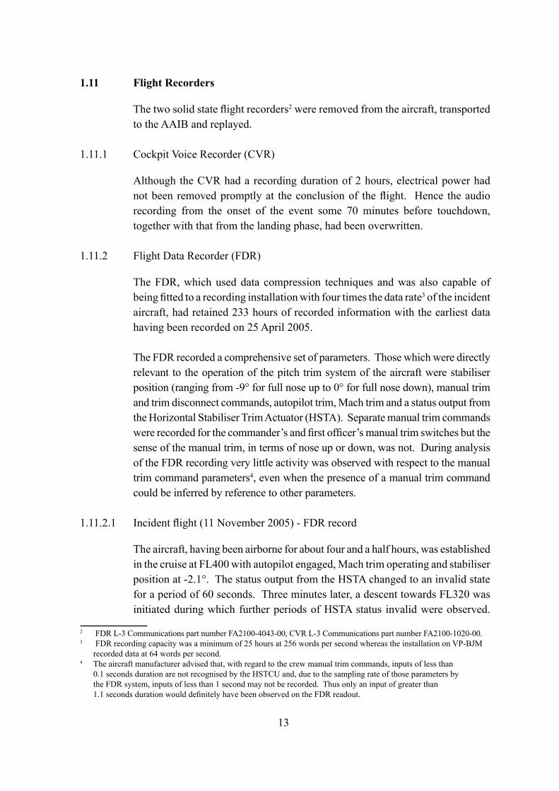
1.6.3.1 Flight controls - horizontal stabiliser pitch trim
Pitch trim is provided by movement of an all-moving horizontal stabiliser. The system control is totally fly-by-wire and can be operated automatically (autopilot pitch trim and mach trim) or manually by switches on each of the control columns. There is no backup mechanical stabiliser trim system.
1 United States Code of Federal Regulations Title 14 Aeronautics and Space Federal Aviation Regulations.
7
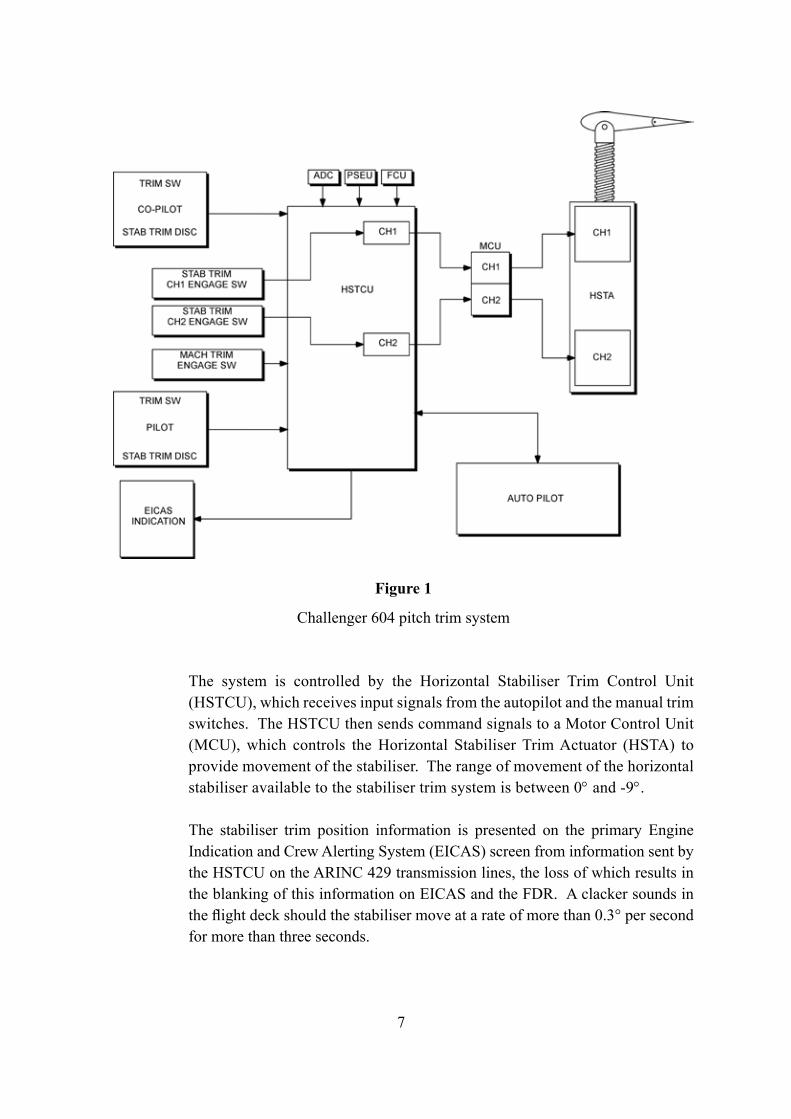
The system is controlled by the Horizontal Stabiliser Trim Control Unit (HSTCU), which receives input signals from the autopilot and the manual trim switches. The HSTCU then sends command signals to a Motor Control Unit (MCU), which controls the Horizontal Stabiliser Trim Actuator (HSTA) to provide movement of the stabiliser. The range of movement of the horizontal stabiliser available to the stabiliser trim system is between 0° and -9°.
The stabiliser trim position information is presented on the primary Engine Indication and Crew Alerting System (EICAS) screen from information sent by the HSTCU on the ARINC 429 transmission lines, the loss of which results in the blanking of this information on EICAS and the FDR. A clacker sounds in the flight deck should the stabiliser move at a rate of more than 0.3° per second for more than three seconds.
Figure 1
Challenger 604 pitch trim system
8
There are two channels, channel 1 (CH1) and channel 2 (CH2) within the HSTCU, MCU and HSTA; these channels are kept separate and can each control the stabiliser trim. The channels are engaged through the use of push-button switches on the centre pedestal, these switches allow the flight crew to engage or disengage each channel separately. In addition there is a switch on each of the control columns which allows the total disconnection of both channels simultaneously, thereby providing a means of preventing further stabiliser trim operation.
Normally both stabiliser trim channels are fully operational, with CH1 in control and CH2 in standby. The HSTCU continually monitors the status of the stabiliser trim system and, should a failure be detected, then the active channel is disengaged. Should CH1 fail or become disengaged then CH2 will automatically take control. Reinstating a disengaged stabiliser trim channel can only be accomplished by manual selection of the push-button switches.
When the flight crew select an HSTCU channel to engage, the HSTA becomes powered and the MCU health is verified. If there are no problems then the MCU sends an ‘HSTA VALID’ signal back to the HSTCU. The ‘HSTA VALID’ signals for each channel are logically compared through an OR gate and sent to the FDR to be recorded as ‘HSTA VALID’. Thus the ‘HSTA VALID’ discrete parameter on the FDR is an indication that at least one channel is engaged with no reported problems with the HSTA or MCU.
Upon channel engagement, the HSTCU commands the MCU to release the HSTA brake and also provides speed and direction commands. If the channel is disengaged, the MCU declares this to the HSTCU and the brake remains engaged, preventing any stabiliser movement by that channel.
1.6.3.2 Flight controls - manual pitch trim
Manual pitch trim is accomplished through switches mounted on the control columns when at least one stabiliser trim channel is engaged. Each control column has two double-throw momentary return-to-centre switches. Both switches on a single control column have to be operated concurrently to complete the wiring circuit and provide a trim command to the HSTCU. The manual trim command moves the stabiliser at a rate of 0.5° per second.
If the autopilot is engaged when manual trim is commanded, and the autopilot is not in its SYNC mode, the autopilot will disengage.
9
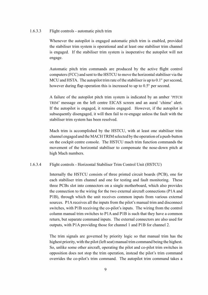
1.6.3.3 Flight controls - automatic pitch trim
Whenever the autopilot is engaged automatic pitch trim is enabled, provided the stabiliser trim system is operational and at least one stabiliser trim channel is engaged. If the stabiliser trim system is inoperative the autopilot will not engage.
Automatic pitch trim commands are produced by the active flight control computers (FCC) and sent to the HSTCU to move the horizontal stabiliser via the MCU and HSTA. The autopilot trim rate of the stabiliser is up to 0.1° per second, however during flap operation this is increased to up to 0.5° per second.
A failure of the autopilot pitch trim system is indicated by an amber ‘PITCH TRIM’ message on the left centre EICAS screen and an aural ‘chime’ alert. If the autopilot is engaged, it remains engaged. However, if the autopilot is subsequently disengaged, it will then fail to re-engage unless the fault with the stabiliser trim system has been resolved.
Mach trim is accomplished by the HSTCU, with at least one stabiliser trim channel engaged and the MACH TRIM selected by the operation of a push-button on the cockpit centre console. The HSTCU mach trim function commands the movement of the horizontal stabiliser to compensate the nose-down pitch at high Mach numbers.
1.6.3.4 Flight controls - Horizontal Stabiliser Trim Control Unit (HSTCU)
Internally the HSTCU consists of three printed circuit boards (PCB), one for each stabiliser trim channel and one for testing and fault monitoring. These three PCBs slot into connectors on a single motherboard, which also provides the connection to the wiring for the two external aircraft connections (P1A and P1B), through which the unit receives common inputs from various external sources. P1A receives all the inputs from the pilot’s manual trim and disconnect switches, with P1B receiving the co-pilot’s inputs. The wiring from the control column manual trim switches to P1A and P1B is such that they have a common return, but separate command inputs. The external connectors are also used for outputs, with P1A providing those for channel 1 and P1B for channel 2.
The trim signals are governed by priority logic so that manual trim has the highest priority, with the pilot (left seat) manual trim command being the highest. So, unlike some other aircraft, operating the pilot and co-pilot trim switches in opposition does not stop the trim operation, instead the pilot’s trim command overrides the co-pilot’s trim command. The autopilot trim command takes a
10
lower priority than the manual trim command, with the Mach trim command having the lowest priority.
Non-volatile memory (NVM) records stabiliser trim system malfunctions and failures, but these failures are only retained until completion of a successful ground test or a manual reset. A fault is only recorded once, into the memory, with no correlation capability to determine when or on which flight the fault occurred.
The HSTCU is located in the avionics compartment under the floor area of the entrance way into the aircraft and also in close proximity to the forward galley. Prevention of rain water, and other moisture and contaminants, finding their way into the avionics compartment is accomplished by the use of additional tape sealing of the floor joints and sealing between the floor and the aircraft structure.
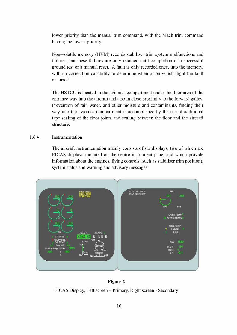
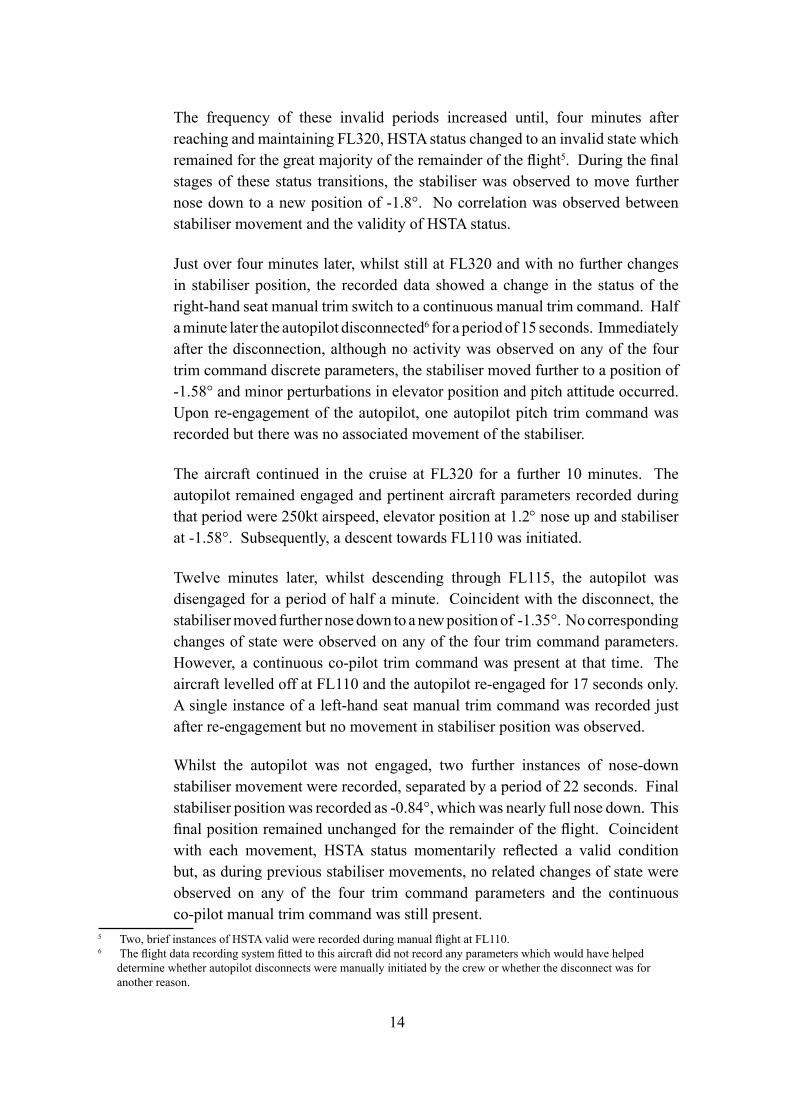
1.6.4 Instrumentation
The aircraft instrumentation mainly consists of six displays, two of which are EICAS displays mounted on the centre instrument panel and which provide information about the engines, flying controls (such as stabiliser trim position), system status and warning and advisory messages.
Figure 2
EICAS Display, Left screen – Primary, Right screen - Secondary
11
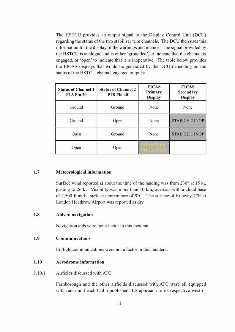
The HSTCU provides an output signal to the Display Control Unit (DCU) regarding the status of the two stabiliser trim channels. The DCU then uses this information for the display of the warnings and memos. The signal provided by the HSTCU is analogue and is either ‘grounded’, to indicate that the channel is engaged, or ‘open’ to indicate that it is inoperative. The table below provides the EICAS displays that would be generated by the DCU depending on the status of the HSTCU channel engaged outputs:
Status of Channel 1P1A Pin 20
Status of Channel 2P1B Pin 40
EICASPrimary Display
EICASSecondary
Display
Ground Ground None None
Ground Open None STAB CH 2 INOP
Open Ground None STAB CH 1 INOP
Open Open STAB TRIMMACH TRIM
1.7 Meteorological information
Surface wind reported at about the time of the landing was from 230° at 15 kt, gusting to 26 kt. Visibility was more than 10 km, overcast with a cloud base of 2,500 ft and a surface temperature of 9°C. The surface of Runway 27R at London Heathrow Airport was reported as dry.
1.8 Aids to navigation
Navigation aids were not a factor in this incident.
1.9 Communications
In-flight communications were not a factor in this incident.
1.10 Aerodrome information
1.10.1 Airfields discussed with ATC
Farnborough and the other airfields discussed with ATC were all equipped with radar and each had a published ILS approach to its respective west or
12
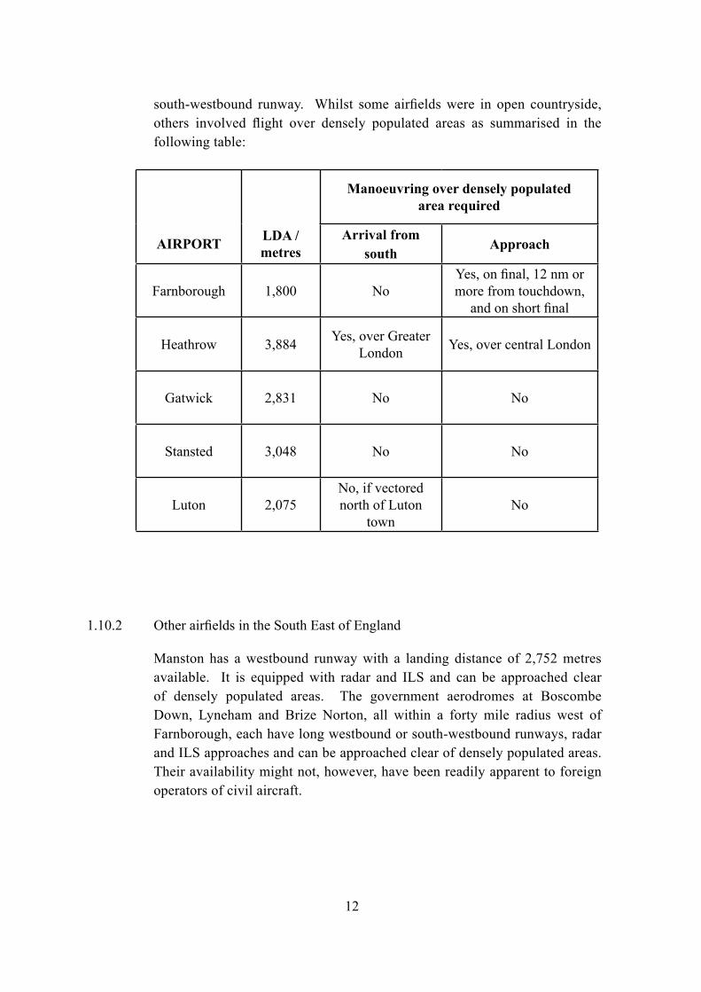
south-westbound runway. Whilst some airfields were in open countryside, others involved flight over densely populated areas as summarised in the following table:
1.10.2 Other airfields in the South East of England
Manston has a westbound runway with a landing distance of 2,752 metres available. It is equipped with radar and ILS and can be approached clear of densely populated areas. The government aerodromes at Boscombe Down, Lyneham and Brize Norton, all within a forty mile radius west of Farnborough, each have long westbound or south-westbound runways, radar and ILS approaches and can be approached clear of densely populated areas. Their availability might not, however, have been readily apparent to foreign operators of civil aircraft.
Manoeuvring over densely populated area required
AIRPORT LDA / metres
Arrival from south
Approach
Farnborough 1,800 NoYes, on final, 12 nm or more from touchdown,
and on short final
Heathrow 3,884 Yes, over Greater London Yes, over central London
Gatwick 2,831 No No
Stansted 3,048 No No
Luton 2,075No, if vectored north of Luton
townNo
13
1.11 Flight Recorders
The two solid state flight recorders2 were removed from the aircraft, transported to the AAIB and replayed.
1.11.1 Cockpit Voice Recorder (CVR)
Although the CVR had a recording duration of 2 hours, electrical power had not been removed promptly at the conclusion of the flight. Hence the audio recording from the onset of the event some 70 minutes before touchdown, together with that from the landing phase, had been overwritten.
1.11.2 Flight Data Recorder (FDR)
The FDR, which used data compression techniques and was also capable of being fitted to a recording installation with four times the data rate3 of the incident aircraft, had retained 233 hours of recorded information with the earliest data having been recorded on 25 April 2005.
The FDR recorded a comprehensive set of parameters. Those which were directly relevant to the operation of the pitch trim system of the aircraft were stabiliser position (ranging from -9° for full nose up to 0° for full nose down), manual trim and trim disconnect commands, autopilot trim, Mach trim and a status output from the Horizontal Stabiliser Trim Actuator (HSTA). Separate manual trim commands were recorded for the commander’s and first officer’s manual trim switches but the sense of the manual trim, in terms of nose up or down, was not. During analysis of the FDR recording very little activity was observed with respect to the manual trim command parameters4, even when the presence of a manual trim command could be inferred by reference to other parameters.
1.11.2.1 Incident flight (11 November 2005) - FDR record
The aircraft, having been airborne for about four and a half hours, was established in the cruise at FL400 with autopilot engaged, Mach trim operating and stabiliser position at -2.1°. The status output from the HSTA changed to an invalid state for a period of 60 seconds. Three minutes later, a descent towards FL320 was initiated during which further periods of HSTA status invalid were observed.
2 FDR L-3 Communications part number FA2100-4043-00, CVR L-3 Communications part number FA2100-1020-00.3 FDR recording capacity was a minimum of 25 hours at 256 words per second whereas the installation on VP-BJM
recorded data at 64 words per second.4 The aircraft manufacturer advised that, with regard to the crew manual trim commands, inputs of less than
0.1 seconds duration are not recognised by the HSTCU and, due to the sampling rate of those parameters by the FDR system, inputs of less than 1 second may not be recorded. Thus only an input of greater than 1.1 seconds duration would definitely have been observed on the FDR readout.
14
The frequency of these invalid periods increased until, four minutes after reaching and maintaining FL320, HSTA status changed to an invalid state which remained for the great majority of the remainder of the flight5. During the final stages of these status transitions, the stabiliser was observed to move further nose down to a new position of -1.8°. No correlation was observed between stabiliser movement and the validity of HSTA status.
Just over four minutes later, whilst still at FL320 and with no further changes in stabiliser position, the recorded data showed a change in the status of the right-hand seat manual trim switch to a continuous manual trim command. Half a minute later the autopilot disconnected6 for a period of 15 seconds. Immediately after the disconnection, although no activity was observed on any of the four trim command discrete parameters, the stabiliser moved further to a position of -1.58° and minor perturbations in elevator position and pitch attitude occurred. Upon re-engagement of the autopilot, one autopilot pitch trim command was recorded but there was no associated movement of the stabiliser.
The aircraft continued in the cruise at FL320 for a further 10 minutes. The autopilot remained engaged and pertinent aircraft parameters recorded during that period were 250kt airspeed, elevator position at 1.2° nose up and stabiliser at -1.58°. Subsequently, a descent towards FL110 was initiated.
Twelve minutes later, whilst descending through FL115, the autopilot was disengaged for a period of half a minute. Coincident with the disconnect, the stabiliser moved further nose down to a new position of -1.35°. No corresponding changes of state were observed on any of the four trim command parameters. However, a continuous co-pilot trim command was present at that time. The aircraft levelled off at FL110 and the autopilot re-engaged for 17 seconds only. A single instance of a left-hand seat manual trim command was recorded just after re-engagement but no movement in stabiliser position was observed.
Whilst the autopilot was not engaged, two further instances of nose-down stabiliser movement were recorded, separated by a period of 22 seconds. Final stabiliser position was recorded as -0.84°, which was nearly full nose down. This final position remained unchanged for the remainder of the flight. Coincident with each movement, HSTA status momentarily reflected a valid condition but, as during previous stabiliser movements, no related changes of state were observed on any of the four trim command parameters and the continuous co-pilot manual trim command was still present.
5 Two, brief instances of HSTA valid were recorded during manual flight at FL110.6 The flight data recording system fitted to this aircraft did not record any parameters which would have helped
determine whether autopilot disconnects were manually initiated by the crew or whether the disconnect was for another reason.
15
The autopilot was re-engaged and the aircraft descended to FL90 with airspeed increasing initially to 280 kt before reducing to 260 kt as the aircraft levelled off. Elevator position at that point was 2° (trailing edge up). From this point until the conclusion of the flight, the right seat manual trim command parameter exhibited sporadic changes in state, the predominant status reflecting a trim command request but progressively changing to reflect a ‘no trim command’ condition by the time that the aircraft landed.
Whilst level, the autopilot was disconnected again and engine speed was reduced from 65% N1 to 50% N1. As airspeed reduced from 260 kt to 180 kt, progressively more nose-up elevator (2° increasing to 6°) was applied to maintain altitude. Engine power was increased and, as airspeed increased to 250 kt, less nose-up elevator surface positions were recorded. During this increase in airspeed the autopilot was re-engaged and aircraft descended to, and levelled at, FL80.
The aircraft made a number of right turns and descended to 3,500ft in order to intercept the localiser for an ILS approach to Runway 27R at Heathrow. Airspeed was reduced to 200 kt by the time that the aircraft levelled off and, with the autopilot still engaged, elevator angles of 3.5° (trailing edge up) were recorded as the aircraft maintained height. From localiser intercept to when the autopilot was disconnected at 1,500 ft, airspeed gradually reduced to 175 kt and average elevator position increased to 4.2° (trailing edge up).
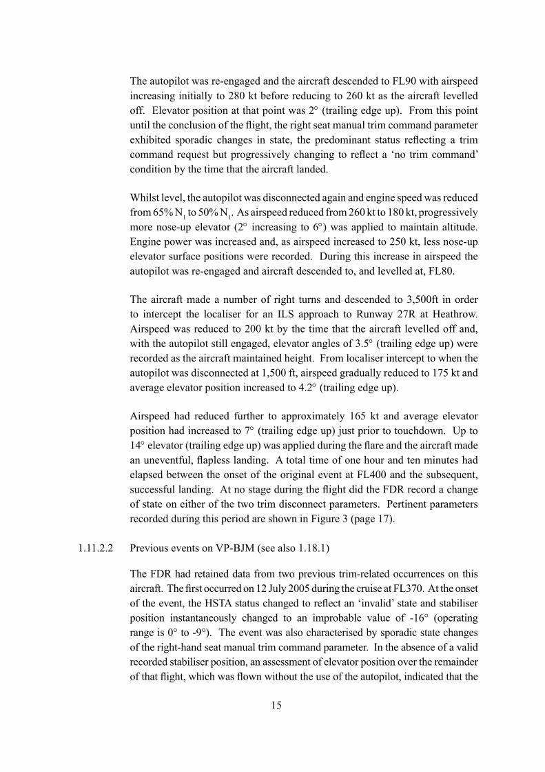
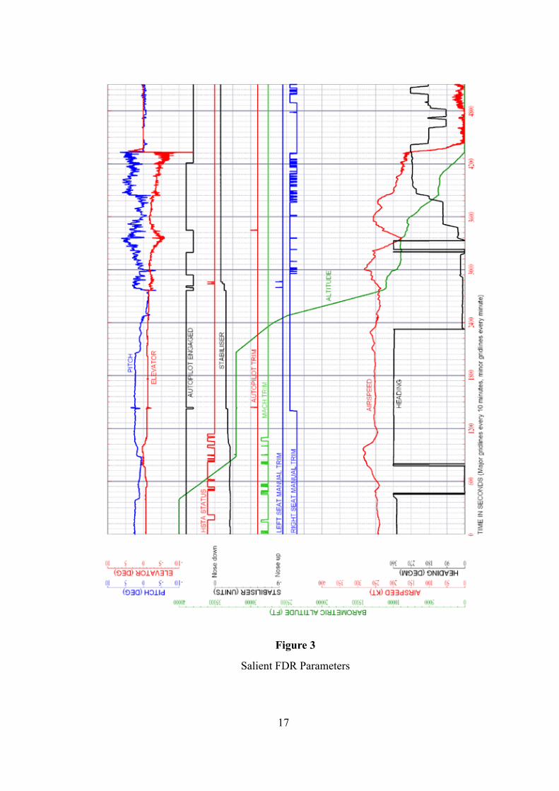
Airspeed had reduced further to approximately 165 kt and average elevator position had increased to 7° (trailing edge up) just prior to touchdown. Up to 14° elevator (trailing edge up) was applied during the flare and the aircraft made an uneventful, flapless landing. A total time of one hour and ten minutes had elapsed between the onset of the original event at FL400 and the subsequent, successful landing. At no stage during the flight did the FDR record a change of state on either of the two trim disconnect parameters. Pertinent parameters recorded during this period are shown in Figure 3 (page 17).
1.11.2.2 Previous events on VP-BJM (see also 1.18.1)
The FDR had retained data from two previous trim-related occurrences on this aircraft. The first occurred on 12 July 2005 during the cruise at FL370. At the onset of the event, the HSTA status changed to reflect an ‘invalid’ state and stabiliser position instantaneously changed to an improbable value of -16° (operating range is 0° to -9°). The event was also characterised by sporadic state changes of the right-hand seat manual trim command parameter. In the absence of a valid recorded stabiliser position, an assessment of elevator position over the remainder of that flight, which was flown without the use of the autopilot, indicated that the
16
stabiliser had moved at various times. This had had a generally nose-down effect during the initial stages of the incident, which changed to a marked nose-up effect prior to the landing. This general assessment was in agreement with the crew report of the event which stated that the stabiliser had been nearly full nose up at the time of the touchdown. 20° flap had been set for that particular landing.
The second event occurred on 14 September 2005 during the cruise at FL400. Again the onset of the event was characterised by a change in the condition of the HSTA status to reflect an ‘invalid’ state. On that occasion the stabiliser position remained unchanged at -2.4° for the remainder of the flight. The autopilot remained engaged until late on the approach and, during that period, changes in airspeed were reflected in changes in elevator angle required to maintain level flight. During the manually flown part of the approach, the selection of 20° flap required an application of 2.5° nose-up elevator (from neutral) to maintain level flight. During the landing phase, as airspeed reduced and the flare was initiated, larger elevator deflections averaging 9.5° nose-up were recorded.
On 18 August 2005 an entry had been made in the aircraft’s technical log with respect to a reported pitch ‘trim runaway on approach’ and, as a consequence, the HSTCU was replaced. No evidence was found within the recorded data to substantiate this tech log entry and all pitch trim related parameters appeared to have been operating normally during the flight in question.
1.12 Aircraft examination
1.12.1 Initial examination (VP-BJM on 11 November 2005)
On arrival at Heathrow, a series of functional checks, with reference to the maintenance manual, were carried out on the pitch trim system and autopilot in VP-BJM; all of the checks were passed with no signs of a problem.
A download of the NVM of the HSTCU revealed that no faults had been recorded and the system was operating normally. It is possible that a ground test may have already been carried out previously, which had cleared the memory.
More detailed checks were then carried out on the system, which included the removal of the HSTCU and the MCU and a full inspection of the wiring. This involved the removal of the carpet and floor boards in the forward galley and entrance way to access the wiring behind the HSTCU. It was noted that there was no evidence of tape sealing having been applied to the floor boards. However, it was also noted that there were no visible signs of moisture, or of staining, on the carpets or floor boards normally associated with moisture contamination, although a Customer Support report did mention traces of water on the insulation blanket
17
Figure 3
Salient FDR Parameters
18
under the passenger door area. The wiring to the rear of the HSTCU was clear of any signs of moisture contamination and also contained a loop to allow moisture to drip toward the floor rather than ‘seep’ into the unit.
All the inspections on the aircraft were satisfactory. The HSTCU and MCU were then sent to the component manufacturer.
1.12.2 Detailed examination
The removed HSTCU, part number 7060-9 serial number 568, was taken to the manufacturer for a detailed examination. The initial BITE check revealed the fault ‘AP high trim rate’, which is triggered if the HSTCU channels detect a difference in the ‘flap in motion’ signal received by the flap computer. A subsequent successful manual and automatic bench test was then carried out.
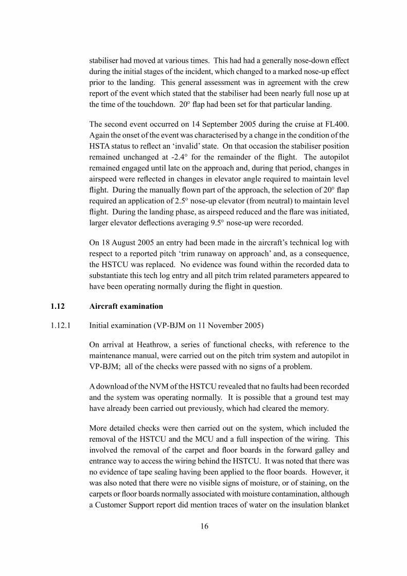
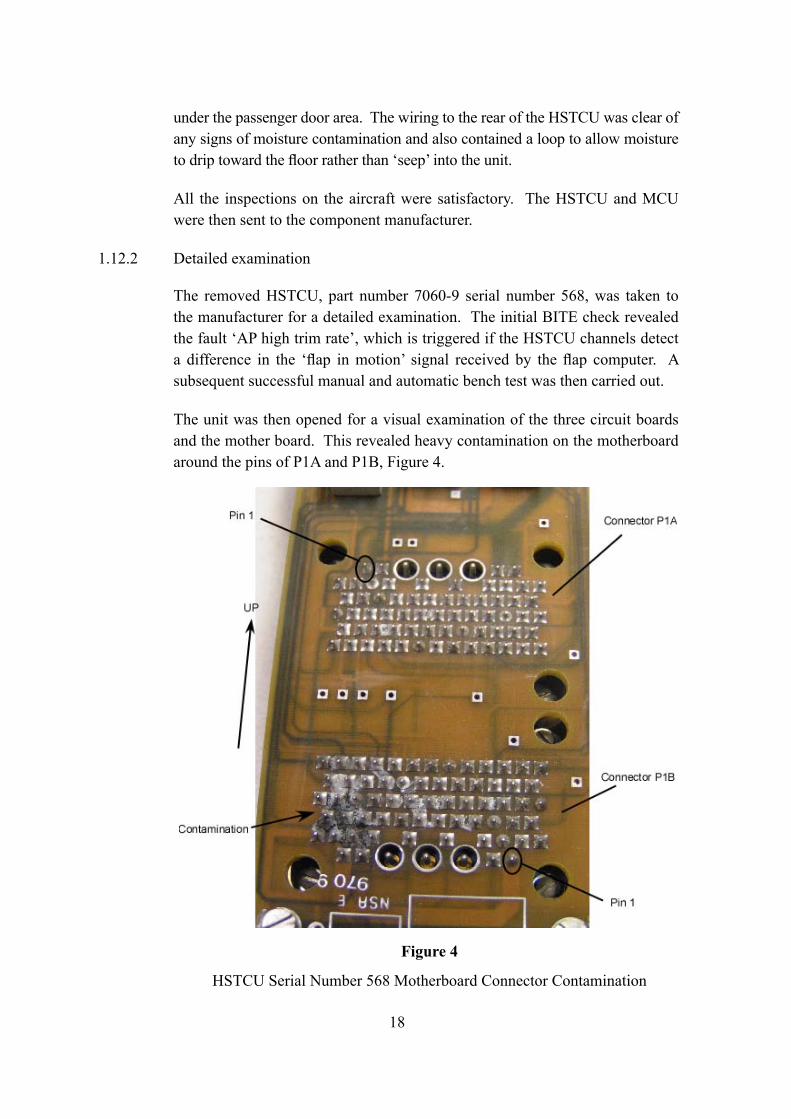
The unit was then opened for a visual examination of the three circuit boards and the mother board. This revealed heavy contamination on the motherboard around the pins of P1A and P1B, Figure 4.
Figure 4
HSTCU Serial Number 568 Motherboard Connector Contamination
19
The contamination was limited to the surface of the board and later analysis revealed it to contain lead, tin and copper oxides. These were the likely products of electro-migration7 in the presence of moisture.
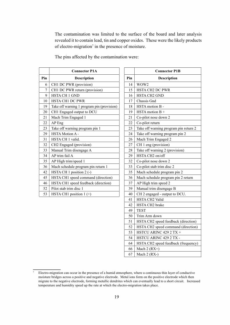
The pins affected by the contamination were:
7 Electro-migration can occur in the presence of a humid atmosphere, where a continuous thin layer of conductive moisture bridges across a positive and negative electrode. Metal ions form on the positive electrode which then migrate to the negative electrode, forming metallic dendrites which can eventually lead to a short circuit. Increased temperature and humidity speed up the rate at which the electro-migration takes place.
Connector P1A Connector P1B
Pin Description Pin Description
6 CH1 DC PWR (provision) 14 WOW27 CH1 DC PWR return (provision) 15 HSTA CH2 DC PWR9 HSTA CH 1 GND 16 HSTA CH2 GND
10 HSTA CH1 DC PWR 17 Chassis Gnd19 Take off warning 1 program pin (provision) 18 HSTA motion B -20 CH1 Engaged output to DCU 19 HSTA motion B +21 Mach Trim Engaged 1 21 Co-pilot nose down 222 AP Eng 22 Co-pilot return23 Take off warning program pin 1 23 Take off warning program pin return 229 HSTA Motion A - 24 Take off warning program pin 231 HSTA CH 1 valid. 26 Mach Trim Engaged 232 CH2 Engaged (provision) 27 CH 1 eng (provision)33 Manual Trim disengage A 28 Take off warning 2 (provision)34 AP trim fail A 29 HSTA CH2 on/off35 AP High trim/speed 1 32 Co-pilot nose down 236 Mach schedule program pin return 1 33 Co-pilot stab trim disc 242 HSTA CH 1 position 2 (-) 35 Mach schedule program pin 245 HSTA CH1 speed command (direction) 36 Mach schedule program pin 2 return46 HSTA CH1 speed feedback (direction) 37 AP High trim speed 252 Pilot stab trim disc 1 39 Manual trim disengage B53 HSTA CH1 position 1 (+) 40 CH 2 engaged - output to DCU.
41 HSTA CH2 Valid42 HSTA CH2 brake49 TEST50 Trim Arm down51 HSTA CH2 speed feedback (direction)52 HSTA CH2 speed command (direction)53 HSTCU ARINC 429 2 TX +54 HSTCU ARINC 429 2 TX -64 HSTA CH2 speed feedback (frequency)66 Mach 2 (RX+)67 Mach 2 (RX-)
20
Tests were later carried out at the manufacturer on the unit in an artificially humid atmosphere, created by water sprays, during which HSTCU channel 2 appeared to be engaged despite being selected as disengaged at the time. A similar test was then carried out to represent flight conditions. The external electrical harness which supplies the HSTCU was cooled to replicate the cooling it would experience at high altitude due to its close proximity to the fuselage. The HSTCU was then placed in a humid atmosphere, using damp towels around the unit. The cooling of the motherboard by the external wiring was thought likely to cause condensation, in a humid atmosphere, to build up on the connectors. After about five hours in this configuration the autopilot trim speed command failed. There was no repeat of the uncommanded trim experienced during the incident flight.
Tests of the MCU, serial number 311, were satisfactory and no fault was found with the unit.
1.13 Medical and pathological information
There were no injuries and no medical factors in this incident.
1.14 Fire
There was no fire.
1.15 Survival aspects
There were no survival aspects to this incident.
1.16 Tests and research
As noted in 1.12.2, there was extensive testing of the avionics units at their manufacturer’s facility in France. This work was conducted with the full participation of the AAIB and the airframe manufacturer, Bombardier.
1.17 Organisational and management information
The aircraft was Bermuda-registered and the operator in Nigeria was a very small organisation. However, there was no evidence that this was a factor in this incident.
21
1.18 Additional information
1.18.1 Previous pitch trim events - VP-BJM (see also 1.11.2.2)
VP-BJM, serial number 5593, was built in September 2004 and had completed 202 hours and 129 landings at the time of the incident. It had been with the operator, Southern Air, since May 2005. The following are details of rectification work carried out following reported defects with the pitch trim.
12 July 2005 event
During the flight the crew reported problems with stabiliser trim channel 1 which disengaged and would not re-engage; at the same time the stabiliser trim position indication on the primary EICAS disappeared from view. The crew also reported that they were unable to carry out any trim commands, even though it appeared that channel 2 had remained engaged. The aircraft was diverted to Toulouse, France, for a safe landing.
Following this event it was noticed that the HSTCU had not been properly located within the electrical rack. The HSTCU was re-racked and the MCU was replaced. The aircraft had completed 113 hours and 79 landings.
18 August 2005 event
The technical log for this day revealed a report of a stabiliser trim runaway during final approach. The corrective action was to remove HSTCU, serial number 1574. Later examination of the motherboard on the removed HSTCU did reveal some contamination which was then cleaned. The aircraft had now completed 144 hours and 95 landings.
14 September 2005 event
During cruise, and after about five hours into the flight, stabiliser trim channel 1 failed along with the autopilot pitch trim and mach trim. Channel 2 appeared to remain engaged, but did not respond to manual trim commands. The aircraft landed safely at Beirut, Lebanon.
Following this event the fault memory of the HSTCU revealed a problem associated with the co-pilot trim switch. The aircraft was flown from Beirut to Berlin, where the trim switch was replaced. In Berlin interrogation of the HSTCU fault memory then revealed a HSTCU and MCU fault; however these cleared after a ground test.
22
The aircraft then flew to Lagos and onward to South Africa, where it was decided to remove HSTCU serial number 314 as well as the MCU and HSTA. Examination of the motherboard on the removed HSTCU did reveal some contamination of the connectors, which was later cleaned off. The aircraft had at total of 167 hours and 106 landings.
1.18.2 Similar contamination findings
From the component manufacturer’s records, several HSTCUs from other aircraft had exhibited similar contamination to that found on the HSTCU removed from VP-BJM. Out of 1,967 units seen by the component manufacturer, 71 had shown signs of contamination, of which 50% had contaminated motherboards and had been fitted to both Challenger 604s and the CRJ 100, 200 series of aircraft.
This event to VP-BJM was the first recorded occurrence of an uncommanded trim movement in which contamination had been found on the HSTCU motherboard. Since this incident there has been at least one other similar incident.
1.18.3 Previous actions taken
In May 2003, the HSTCU manufacturer issued a Service Information Letter (SIL) due to some HSTCUs, removed from CRJ 100 and CRJ 200 aircraft types, being found, during workshop visits, with signs of moisture contamination on the three main PCB assemblies. The recommended ‘fix’ was to install a protective tape over the top, and one inch down each side, of the unit. The aircraft and component manufacturers assessed that the application of the tape would not have any affect on the unit’s internal operation. The modification was not mandated and it was not followed up with any aircraft manufacturer-issued documentation, although they did endorse the modification.
This tape had been applied to the HSTCU removed from VP-BJM following the incident.
1.18.4 Certification regulations relating to pitch trim
The Challenger 604 stabiliser trim system is fully fly-by-wire and does not have a mechanical backup, commonly found on other large passenger aircraft. The regulations to which the aircraft was certified do not require such a mechanical backup system, provided a failure within the designed system that would prevent safe flight can be demonstrated to be extremely improbable. This is defined in FAR 25.1309 which requires:
23
‘…(b) The airplane systems and associated components, considered separately and in relation to other systems, must be designed so that—
(1) The occurrence of any failure condition which would prevent the continued safe flight and landing of the airplane is extremely improbable, and
(2) The occurrence of any other failure conditions which would reduce the capability of the airplane or the ability of the crew to cope with adverse operating conditions is improbable….’
During the design of the pitch trim system the aircraft manufacturer determined that any failure of the system would be classified as ‘major’ as defined in FAA Advisory Circular 25.1309-1A, which states:
‘Major: Failure conditions which would reduce the capability of the airplane or the ability of the crew to cope with adverse operating conditions to the extent that there would be for example, —
A significant reduction in safety margins or functional capabilities, a significant increase in crew workload or in conditions impairing crew efficiency, or some discomfort to occupants; or
In more severe cases, a large reduction in safety margins or functional capabilities, higher workload or physical distress such that the crew could not be relied on to perform tasks accurately or completely, or adverse affects to occupants.’
The system was thus designed to have two independent control systems and it was demonstrated that no single failure would affect continued safe flight and landings. It was also demonstrated to the airworthiness regulator that any combination of failures that could affect the continued safe flight would be extremely improbable (those with a probability of 1 x 10⁻⁹ or less). Therefore the system complied with the regulations in force at the time.
1.18.5 Previous Recommendations
In 1997 the AAIB issued its report on the incident to Boeing 737-236 Advanced, G-BGJI 15 nm north-west of Bournemouth International Airport, which occurred on 22 October 1995 (AAIB report 1/98). It was discovered that the yaw damper coupler connector had become contaminated with fluid such that adjacent pins
24
altered signals into the coupler leading to a forced ‘dutch roll’. The location of the yaw damper coupler was in the electrical bay beneath the cabin floor in the area of the door entrance way, galley and toilets. Several recommendations were made including:
‘The CAA with the FAA review FARs and JARs with a view to requiring that the location of electronic equipment be arranged during the aircraft design so as to minimise the potential for contamination by fluid ingress, with the intention of ensuring that the equipment, connectors and wiring are provided with protection consistent with reliable operation less heavily dependant on maintenance practices. (Safety Recommendation 97-61)’
The CAA response was:
‘CAA Response
The Authority does not accept this Recommendation.
The type certification basis of the Boeing 737-200 did not contain specific requirements in respect of minimisation of fluid ingress, nor was there any guidance material available at the time of initial certification in July 1968. Guidance material which addressed the issue of fluid contamination was first published in FAA Advisory Circular (AC) 25.1309-1 in September 1982, and hence did not apply to this type.
The Authority is satisfied that current JARs contain adequate guidance to protect against contamination of electronic equipment by fluid ingress. In particular, ACJ No 2 to JAR 25.1309 and AMJ 25.1309 7e(3) contain specific guidance material. FAA Advisory Circular AC 25.1309-1A paragraph 7e(3) contains equivalent guidance material to that provided in AMJ 25.1309.
CAA Status – Closed’
25
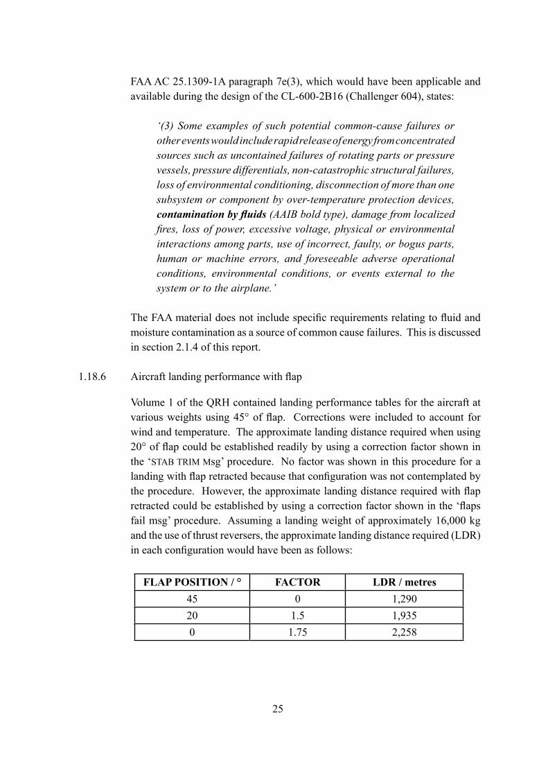
FAA AC 25.1309-1A paragraph 7e(3), which would have been applicable and available during the design of the CL-600-2B16 (Challenger 604), states:
‘(3) Some examples of such potential common-cause failures or other events would include rapid release of energy from concentrated sources such as uncontained failures of rotating parts or pressure vessels, pressure differentials, non-catastrophic structural failures, loss of environmental conditioning, disconnection of more than one subsystem or component by over-temperature protection devices, contamination by fluids (AAIB bold type), damage from localized fires, loss of power, excessive voltage, physical or environmental interactions among parts, use of incorrect, faulty, or bogus parts, human or machine errors, and foreseeable adverse operational conditions, environmental conditions, or events external to the system or to the airplane.’
The FAA material does not include specific requirements relating to fluid and moisture contamination as a source of common cause failures. This is discussed in section 2.1.4 of this report.
1.18.6 Aircraft landing performance with flap
Volume 1 of the QRH contained landing performance tables for the aircraft at various weights using 45° of flap. Corrections were included to account for wind and temperature. The approximate landing distance required when using 20° of flap could be established readily by using a correction factor shown in the ‘STAB TRIM Msg’ procedure. No factor was shown in this procedure for a landing with flap retracted because that configuration was not contemplated by the procedure. However, the approximate landing distance required with flap retracted could be established by using a correction factor shown in the ‘flaps fail msg’ procedure. Assuming a landing weight of approximately 16,000 kg and the use of thrust reversers, the approximate landing distance required (LDR) in each configuration would have been as follows:
FLAP POSITION / ° FACTOR LDR / metres45 0 1,29020 1.5 1,9350 1.75 2,258
26
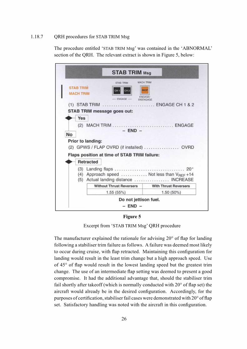
1.18.7 QRH procedures for STAB TRIM Msg
The procedure entitled ‘STAB TRIM Msg’ was contained in the ‘ABNORMAL’ section of the QRH. The relevant extract is shown in Figure 5, below:
Figure 5
Excerpt from ‘STAB TRIM Msg’ QRH procedure
The manufacturer explained the rationale for advising 20° of flap for landing following a stabiliser trim failure as follows. A failure was deemed most likely to occur during cruise, with flap retracted. Maintaining this configuration for landing would result in the least trim change but a high approach speed. Use of 45° of flap would result in the lowest landing speed but the greatest trim change. The use of an intermediate flap setting was deemed to present a good compromise. It had the additional advantage that, should the stabiliser trim fail shortly after takeoff (which is normally conducted with 20° of flap set) the aircraft would already be in the desired configuration. Accordingly, for the purposes of certification, stabiliser fail cases were demonstrated with 20° of flap set. Satisfactory handling was noted with the aircraft in this configuration.
27
The manufacturer’s flight test department estimated that with the stabiliser failed at the zero degrees position, and a forward CG, flight with flap retracted would require approximately 13º of nose-up elevator, 5 inches of aft column motion and approximately 50 lb aft column force. With 20° of flap set, the corresponding values would be approximately 14.5º of elevator, 5.5 inches of aft column travel and approximately 53 lb of aft column force. With more nose-down trim, the forces would increase but the difference between the flap retracted and 20° flap cases would remain less than 5lb. It concluded that, in terms of overall controllability, the advantage of a small decrease in aft force required, achieved by landing flapless, would be offset by the increased approach speed.
Certification standards for the category of aeroplane of which the Challenger 604 is a member have been harmonised in EASA certification specification CS-25 – Certification Specifications for Large Aeroplanes and FAR Part 25 – Airworthiness Standards: Transport Category Airplanes. In each document, section 25.143 describes the general requirements for controllability and manoeuvrability. Excerpts from CS 25.143 are quoted here and may be considered representative of both documents.
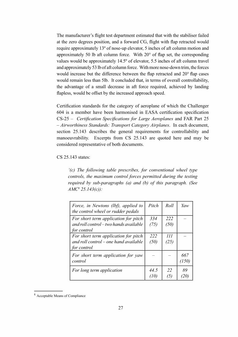
CS 25.143 states:
‘(c) The following table prescribes, for conventional wheel type controls, the maximum control forces permitted during the testing required by sub-paragraphs (a) and (b) of this paragraph. (See AMC8 25.143(c)):
8 Acceptable Means of Compliance
Force, in Newtons (lbf), applied to the control wheel or rudder pedals
Pitch Roll Yaw
For short term application for pitch and roll control – two hands available for control
334(75)
222(50)
–
For short term application for pitch and roll control – one hand available for control
222(50)
111(25)
–
For short term application for yaw control
– – 667(150)
For long term application 44.5(10)
22 (5)
89(20)
28
AMC 25.143(c) states:
‘1. The maximum forces given in the table in CS 25.143(c) for pitch and roll control for short term application are applicable to manoeuvres in which the control force is only needed for a short period. Where the manoeuvre is such that the pilot will need to use one hand to operate other controls (such as the landing flare or go-around, or during changes of configuration or power resulting in a change of control force that must be trimmed out) the single-handed maximum control forces will be applicable. In other cases (such as takeoff rotation, or manoeuvring during en-route flight) the two handed maximum forces will apply.
2. Short term and long term forces should be interpreted as follows:
Short term forces are the initial stabilised control forces that result from maintaining the intended flight path during configuration changes and normal transitions from one flight condition to another, or from regaining control following a failure. It is assumed that the pilot will take immediate action to reduce or eliminate such forces by re-trimming or changing configuration or flight conditions, and consequently short term forces are not considered to exist for any significant duration. They do not include transient force peaks that may occur during the configuration change, change of flight condition or recovery of control following a failure.
Long term forces are those control forces that result from normal or failure conditions that cannot readily be trimmed out or eliminated.’
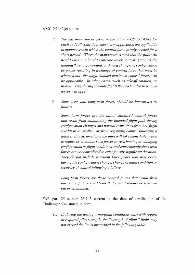
FAR part 25 section 25.143 current at the date of certification of the Challenger 604, stated, in part:
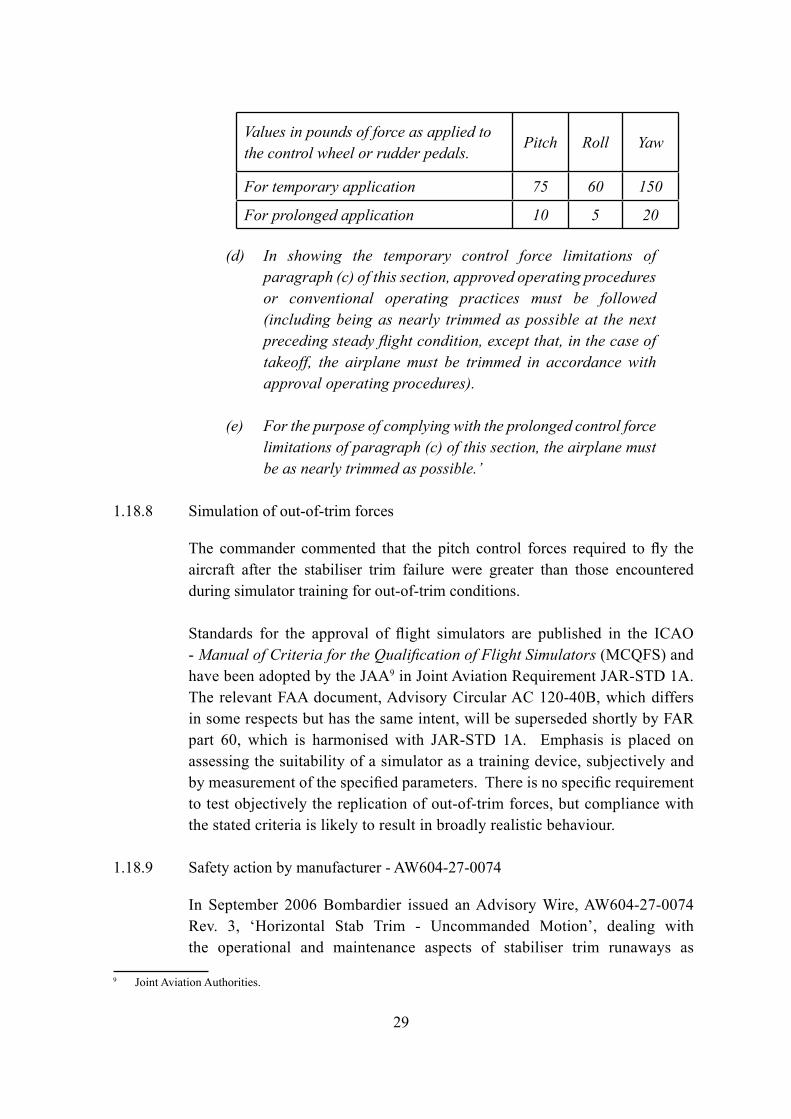
‘(c) If, during the testing… marginal conditions exist with regard to required pilot strength, the “strength of pilots” limits may not exceed the limits prescribed in the following table:
29
(d) In showing the temporary control force limitations of paragraph (c) of this section, approved operating procedures or conventional operating practices must be followed (including being as nearly trimmed as possible at the next preceding steady flight condition, except that, in the case of takeoff, the airplane must be trimmed in accordance with approval operating procedures).
(e) For the purpose of complying with the prolonged control force limitations of paragraph (c) of this section, the airplane must be as nearly trimmed as possible.’
1.18.8 Simulation of out-of-trim forces
The commander commented that the pitch control forces required to fly the aircraft after the stabiliser trim failure were greater than those encountered during simulator training for out-of-trim conditions.
Standards for the approval of flight simulators are published in the ICAO - Manual of Criteria for the Qualification of Flight Simulators (MCQFS) and have been adopted by the JAA9 in Joint Aviation Requirement JAR-STD 1A. The relevant FAA document, Advisory Circular AC 120-40B, which differs in some respects but has the same intent, will be superseded shortly by FAR part 60, which is harmonised with JAR-STD 1A. Emphasis is placed on assessing the suitability of a simulator as a training device, subjectively and by measurement of the specified parameters. There is no specific requirement to test objectively the replication of out-of-trim forces, but compliance with the stated criteria is likely to result in broadly realistic behaviour.
1.18.9 Safety action by manufacturer - AW604-27-0074
In September 2006 Bombardier issued an Advisory Wire, AW604-27-0074 Rev. 3, ‘Horizontal Stab Trim - Uncommanded Motion’, dealing with the operational and maintenance aspects of stabiliser trim runaways as
9 Joint Aviation Authorities.
Values in pounds of force as applied to the control wheel or rudder pedals.
Pitch Roll Yaw
For temporary application 75 60 150
For prolonged application 10 5 20
30
experienced by VP-BJM. The document informed operators of the FAA and Transport Canada Airworthiness Directives. Regarding crew procedure and flap selection, the document stated:
‘In the event of a stabiliser trim runaway, the AFM procedure recommends a flap selection of 20°. While this will increase the nose-down force slightly (approximately 5lbs) when the stabiliser is in the full nose-down position, having flaps at 20° provides more runway options for landing. This procedure has been flown by Bombardier flight test pilots to validate that the change in control forces is not significant.’
31
2 Analysis
In this serious incident, a severe out-of-trim condition occurred which this crew were able to manage but which, in a less favourable operational environment, could result in the loss of an aircraft. The following analysis deals with the technical issues underlying the out-of-trim condition, the crew’s actions and the question of flight over densely populated areas by aircraft in an emergency.
2.1 Technical failures
Following the incident, the initial testing of the aircraft did not reveal any pre-existing defects that could explain the reported problems. Indeed, the tests of each of the components within the system were all satisfactory. The NVM on the HSTCU was not useful as it showed no faults when it was interrogated. It is possible that a ground test was carried out prior to the NVM being read, leading to erasure of useful information.
2.1.1 Failure of the HSTCU
It was only after the HSTCU had been removed from the aircraft and sent to the component manufacturer that the probable cause of the incident was located. The contamination found on the motherboard of the HSTCU can be directly related to the problems experienced by the flight crew of VP-BJM during the incident flight.
During testing of the HSTCU in the laboratory, it was found that in dry conditions the unit would operate satisfactorily. However, when moisture was applied faults would start to occur. The most pertinent experiment was to simulate an in-flight condition by cooling the external wiring while exposing the HSTCU to an artificial hot and humid environment. Faults appeared after about five hours due to the cold external wiring cooling the motherboard and allowing condensate to build up, due to the humid air.
The first indication of a problem occurred about four and half hours into the flight with the indication of autopilot ‘PITCH TRIM’ fault. This was similar to the time it took for condensate to form during the laboratory tests (five hours). The fault could have occurred due to the moisture and its related contaminates causing a short between pins 18 and 19 (HSTA position feedback) of connector P1B.
About 30 minutes later the FDR showed the ‘HSTA valid’ signal change to ‘invalid’, at the same time the flight crew reported the messages ‘STAB TRIM’ and ‘MACH TRIM’, indicating that both channel 1 and channel 2 of the HSTCU
32
had failed. This was probably due to the contamination building up and starting to cause multiple and intermittent shorts, leading to the HSTCU failing the channels.
The intermittent nature of the shorts was indicated in the FDR data, with the ‘HSTA valid’ state changing frequently. The changes in state indicated that the flight crew were able to engage the HSTCU channels for short periods, but with the HSTCU continuing to detect faults and failing the channel again.
With the aircraft in cruise, the status of the co-pilot trim on the FDR changed to a continuous manual command and, although the direction was not recorded, it was likely to be in the nose-down sense. The manual trim command would only be applicable when a stabiliser trim channel was engaged. From the FDR, the ‘HSTA valid’ discrete indicated a channel was engaged on at least two occasions coincident with a nose-down trim movement. However, there were also points at which the stabiliser moved further nose down without the HSTA status being ‘valid’, indicating a trim movement with no channel engaged. This should not be possible and was probably due to the sampling rates on the FDR parameter missing the short duration of channel engagement.
The apparent manual trim command from the co-pilot can be related to the contamination of connector P1B. For the manual trim to occur the HSTCU needs a concurrent zero volts on pins 21 (co-pilot nose-down trim 1) and 32 (co-pilot nose-down trim 2). With the contamination, pin 21 could have shorted to pin 22 (co-pilot trim return) which is ‘ganged’ to zero volts within the unit. Similarly, pin 32 could have shorted to pin 33 (co-pilot stab trim disc 2) and then found a path to zero volts. This could have been through the aircraft wiring, by way of the normally-closed stabiliser trim disconnect switch to the uncontaminated pin 34 (co-pilot stab trim disconnect return) which was ‘ganged’ to zero volts within the unit.
The commander reported that he had tried to apply a nose-up command, but the aircraft responded with a nose-down trim. The expectation would be for any trim command from the pilot to override that of the co-pilot. From the FDR, the pilot applied his nose-up trim command just prior to the channel becoming engaged, with the expectation of a nose-up trim. However, as the commander released his trim switch the nose-down trim command from the contamination would have caused an uncommanded nose-down trim, giving the impression that the pilot’s trim command had reversed.
33
During the incident, the flight crew reported the engagement and disengagement of channel 2 of its own accord, indicated by the intermittent illumination of either ‘STAB TRIM’ to indicate the channel failure or ‘STAB CH1 INOP1’, indicating channel 2 was engaged and operational. The flight crew also reported that when channel 2 appeared to be engaged they were not able to initiate any trim commands. The anomaly with this report is that, although the HSTCU can disengage a channel, by design it cannot engage a channel automatically: this can only be accomplished by manual switch selection in the flight deck. Also, the expectation would be that, with a channel engaged, the manual trim would be operational.
The anomalies can also be explained by the contamination of P1B. With zero volts on pin 40 (channel 2 engaged), the DCU takes this analogue discrete to mean that channel 2 of the HSTCU is engaged and displays the appropriate warnings on the EICAS. Therefore, it is possible that the moisture contamination caused pin 40 to short to zero volts intermittently and indicate that channel 2 was engaged, when in fact it was disengaged.
2.1.2 Cause of failure
The contamination, when sampled, was limited to the surface of the PCB and contained corrosion products of lead, tin and copper. These were likely products as a result of electro-migration which had occurred due to the combination of three factors: circuit board surface contamination, presence of moisture and potential (voltage) difference between pins. At its worst, electro-migration can lead to metallic dendrites and the continuous shorting of pins. However, the HSTCU from VP-BJM passed the bench tests when it was dry and it is unlikely that the corrosion had reached that stage. The faults experienced seemed only occur when the board was contaminated with moisture, borne out later by the laboratory testing.
The source of the moisture was first thought to be external water ingress, as had been experienced in the past, leading to the issue by the manufacturer of a SIL to apply tape to the top of the unit. This was also thought to be the case due to the location of the HSTCU, directly below the floor of the aircraft entrance way and galley. However, inspection of the aircraft did not reveal any signs of water penetration either on the floor or through the floor boards into the electrical bay, nor were there any signs of external water contamination on the HSTCU.
This meant that the moisture must have been generated within the unit and was probably related to humidity. The aircraft operated predominately from a hot and humid climate. During cruise the stabiliser trim wiring loom can become
34
cooled, due to its close proximity to the fuselage skin, which in turn would cool the connectors and the motherboard at the rear of the HSTCU. The humid air would come into contact with the cooling motherboard and allow moisture to condense on the contacts. This would not occur immediately and would need to develop over a period of time in flight. During laboratory testing, faults occurred after about five hours, and on the incident flight it took four and half hours for the first faults to appear. Another factor that led to the moisture contamination causing the faults was the lack of environmental protection, either to the HSTCU itself or to the motherboard and its connectors.
As the aircraft has no mechanical backup, the two stabiliser trim channels are required to be fully independent and not affected by common failure modes, such as moisture contamination. The moisture that formed and contaminated both connectors P1A and P1B, affected the common inputs for the stabiliser trim system and led to the uncommanded trim nose-down command and other failures which affected both stabiliser trim channels. It also became apparent during the investigation that the contamination had been found on previous occasions, not only on the HSTCU removed previously from VP-BJM, but also on other units from Challenger 604 and CRJ100 and CJ200 aircraft. There is therefore a continuing risk that an uncommanded trim or loss of stabiliser trim, due to moisture contamination, could occur on any aircraft type fitted with this HSTCU. The AAIB therefore made the following recommendation in Special Bulletin S3/2005:
It is recommended that Transport Canada ensure that Bombardier Aerospace eliminate the risk of contamination affecting the operation of the horizontal stabiliser trim control system fitted in the Challenger 604 and other Bombardier aircraft with similar trim systems. (Safety Recommendation 2005-147)
2.1.3 Action taken since Recommendation 2005-147
In the USA, on 6 July 2006, there was a similar incident of stabiliser trim uncommanded movement to a Challenger 604, registration N724MF. The investigation soon discovered similar contamination of the HSTCU motherboard as that found on VP-BJM. As a result of the two incidents and recommendation 2005-147, Transport Canada issued mandating action via Airworthiness Directives (AD) CF-2006-20R1 and CF-2006-21R1, in addition the FAA issued AD 2006-18-04 that was shortly superseded by AD 2006-22-06. These ADs required the following:
35
1) Amend the AFM to incorporate additional procedures to halt an uncommanded pitch trim movement, should it occur in flight.
2) Place identifying collars on the STAB CH1 HSTCU CB and STAB CH2 HSTCU CB.
3) Brief crews prior to every flight on the location of the HSTCU CBs and to carry out a functional check of the stabiliser trim system.
4) Modify the HSTCU by protecting the circuit boards against the effects of moisture, by 16 October 2007 (Bombardier SB601R-27-147).
2.1.4 Regulations and aircraft design
The aircraft was certified to FAR 25, and part of this original certification was a requirement to comply with FAR 25.1309. According to the aircraft manufacturer, it was demonstrated that the stabiliser trim system did comply with this requirement.
However, this investigation has revealed that the stabiliser trim system can be affected by a single common cause failure, that of moisture ingress into the HSTCU and, in particular, the motherboard. According to the FAA AC 25.1309-1A paragraph 7e(3) (see 1.18.5), when carrying out the analysis for compliance, common cause failures have to be taken into account including contamination by fluids.
In 1997 the AAIB issued Safety Recommendation 97-61 following an investigation into a control upset to a Boeing 737 which was related to fluid contamination of the yaw damper coupler. The response to this recommendation was that, although FAA AC 25.1309-1A did not apply to the Boeing 737 at the time of design, the current guidance is adequate to protect against contamination of electronic equipment by fluid ingress. Clearly, for the Challenger 604, CRJ100 and CRJ200 stabiliser trim system, this was not the case.
The NTSB recently investigated incidents to Bombardier CRJ200 aircraft, in which there was a temporary loss of all the electronic flight instrument displays (EFIS). This was due to overheating of a contactor, located in the avionics compartment, resulting in a fire. It was found that the contactor had become contaminated with water which had seeped though the floor boards in the main
36
cabin entrance way. This was another example where water contamination was a common failure mode for which adequate protection was not provided.
It is clear, therefore, both from this incident and others, that the regulation and guidance material relating to fluid contamination as a common cause failure of electrical components, such as those in the electronics bay, is not adequate. The following recommendation is made:
It is recommended that the EASA, in collaboration with other airworthiness authorities, including the FAA and Transport Canada, amend their requirements relating to the design and installation of electronic components in aircraft, so that fluid and moisture contamination, as a source of common cause failures, is specifically taken into account and adequate measures take place to minimise the risk. (Safety Recommendation 2007-061)
2.2 Crew actions
2.2.1 Flap selection following stabiliser trim failure
Although the commander was aware of the QRH procedure to be followed in the event of a ‘STAB TRIM’ message, he elected to land with the flaps retracted because he believed that selecting 20° of flap, as recommended, would increase the forces required to maintain control of the aircraft in pitch. Information provided by the manufacturer suggested that, although he was correct in this assumption, the additional aft column force required to fly the aircraft with 20° of flap would not have been significant, whereas a flapless approach would require a higher approach speed and greater landing distance.
The manufacturer established the QRH ‘STAB TRIM Msg’ procedure on the assumption that a stabiliser trim failure would occur during cruising flight and result in minimal out-of-trim forces. In practice, the commander stated that great physical effort was required to fly the aircraft and commented that any increase in this effort, occasioned for example by the addition of flap, might have rendered control of the aircraft beyond the combined capability of the crew. Inspection of the table of LDRs in each configuration (1.18.6) shows that, even with 20° of flap selected, the runway at Farnborough would have been too short. Given that a diversion to a longer runway was inevitable, the commander’s decision to land with flap did not further reduce his choice of runway.
In determining the appropriate flap setting for an approach with full nose-down trim, the pitch control forces experienced by the crew of VP-BJM
37
should be assessed in relation to the ‘prolonged’ or ‘long term’ limits quoted in CS 25.143 and FAR 25.143. The pitch control force of 53 lb, which the manufacturer estimated would be required to operate the aircraft with 20° of flap set, exceeds those limits. In the case of approach and landing (which constitute a ‘temporary’ or ‘short term’ condition) this value, whilst below the limit applicable at the time of certification, is above the limit applicable under current requirements since the pilot is assumed to have only one hand available for control during the landing flare.
During the investigation, the AAIB considered a recommendation to the manufacturer and regulators requiring specific flight tests to determine the control forces required to operate Bombardier CL600-2B16 (604 Variant) aircraft with full nose-down trim using 20° of flap. However, the actions by Bombardier in examining this configuration in flight test, before the issue of AW604-27-0074, made this recommendation unnecessary.
2.2.2 Simulation of out-of-trim forces
Under existing provisions there is no specific requirement for flight simulators to imitate accurately the control forces that would be encountered in the event of a trim failure, although compliance with other criteria specified in the ICAO MCQFS and equivalent documents published by the JAA and the FAA is likely to result in a representative simulation of the behaviour of the subject aircraft. A simulator approved in accordance with existing standards is not, however, designed to reproduce the complete experience of operating a real aircraft out of trim for a considerable length of time.
2.2.3 Flight over densely populated areas by aircraft in an emergency
Having established that a flapless landing would be required, the commander elected to divert to Stansted. When, with some prompting, the crew declared an emergency they were informed of the alternatives and decided at first to continue to Stansted. The pilots realised, however, that the physical effort of controlling the aircraft could not be sustained. Considering that fact in isolation, it was prudent to remain within the vicinity of the closest suitable runway, which at the time that LTCC acknowledged the MAYDAY was Heathrow.
LTCC controllers identified the closest alternative airports but did not seek to influence the commander’s conduct of the flight. Nevertheless, when the nature of the problem became apparent LTCC informed VP-BJM that the closest suitable runway was London Gatwick, 20 nm to the east. The commander reported, however, that, having decided that they would divert to Stansted,
38
and faced with the considerable difficulties of operating the aircraft, the pilots were not immediately receptive to this alternative. Because LTCC did not attempt to emphasise the alternatives, the crew naturally persisted with the plan they had initiated.
In a separate but relevant occurrence on 24 April 2004, a Boeing 747 diverted to Heathrow after one engine failed and the crew determined that the three remaining engines were not producing the selected thrust. The AAIB investigation10 found that in the process of diverting to Heathrow, the aircraft flew over some of the most congested parts of London in a gliding configuration from which a safe landing was not reasonably assured. The report stated:
’It must be considered where the proper balance of safety rests when considering the plight of persons onboard an aircraft in difficulties in relation to persons on the ground in densely populated and congested areas such as those of central and greater London. The balance between delaying an aircraft’s landing by routeing it around a congested area, versus the aircraft’s condition deteriorating and possibly leading to an accident outside the congested area, should be considered. Moreover, circumstances under which the condition of the aircraft, through damage or technical failure, may pose an unacceptable danger to persons on the ground requiring non-standard routeing, should be defined.’
The following Safety Recommendation was made:
‘The Civil Aviation Authority (CAA) should review the guidance provided in the Manual of Air Traffic Services (MATS) Part 1 and Civil Aviation Publication (CAP) 475 (The Directory Of CAA Approved Organisations) and consider whether ATC unit Training for Unusual Circumstances and Emergencies (TRUCE) plans adequately prepare controllers to handle aircraft in emergency, and in particular, whether sufficient guidance is provided on the avoidance of built-up areas when vectoring aircraft in emergency. Where considered necessary, this guidance should be amended as soon as practicable. (Recommendation 2005 – 069)’
10 The report of this investigation, reference EW/C2004/04/04, was published in Bulletin 1/2006 and is available from the AAIB website, www.aaib.gov.uk.
39
The CAA response was:
‘CAA response
The CAA accepts this recommendation.
The CAA has reviewed the guidance provided in MATS Part 1 and CAP 745, as well as that contained in CAP 744 (United Kingdom Manual of Personnel Licensing – Air Traffic Controllers) in respect of the Training in Unusual Circumstances and Emergencies (TRUCE) Scheme and CAP 584 (Requirements for Initial Air Traffic Control Training).
MATS Part 1 will be modified to enhance the guidance to air traffic controllers regarding the management of aircraft in emergency where the intended flight path passes over densely populated areas. Additionally, the CAA will shortly write to all surveillance equipped Air Navigation Service Providers (ANSPs) and the relevant training institutions to highlight the need to incorporate suitable training for this additional consideration into unit TRUCE plans. The amendment to MATS Part 1 will be promulgated on 28 April 2006.
The CAA will, however, continue to emphasise that the ultimate decision in such circumstances rests with the aircraft commander.’
The relevant amended section of MATS Part 1 contains the following text:
‘It is desirable that aircraft in emergency should not be routed over densely populated areas, particularly if there is reason to believe that the aircraft’s ability to remain in controlled flight is compromised or that parts of the aircraft could detach in flight. If this is inconsistent with providing the most appropriate service to the aircraft, for example when any extended routeing could further jeopardise the safety of the aircraft, the most expeditious route is the one that should be given. Where possible, when expeditious routeing is not required, suggestions of alternative runways or aerodromes together with the rationale that the routeing would avoid densely populated areas and be consistent with safety, shall be passed to the pilot and his intentions requested.’
In this instance, the aircraft landed safely. It is accepted that the question of flight over densely populated areas by aircraft in a degraded condition will continue to be contentious.
40
3. Conclusions
(a) Findings
1. The flight crew members were properly licensed to conduct the flight.
2. The flight was uneventful until the autopilot pitch trim failed about four and a half hours into the flight, followed by the stabiliser trim system.
3. Attempts by the crew to re-engage the stabiliser trim channels were not successful.
4. The stabiliser occasionally trimmed ‘aircraft nose down’, despite applications of nose-up trim commands, and reached almost full nose down.
5. To counteract the runaway trim, both flight crew members had to apply prolonged aft pressure on the control column.
6. The aircraft diverted to London Heathrow for a landing with flap retracted, although the QRH required 20° flap following a stabiliser trim failure.
7. The commander made the decision to land with flap retracted, as he was concerned that applying flap would substantially increase control loads required for level flight.
8. The runaway trim condition was caused by electrical shorting, in the presence of moisture, within the Horizontal Stabiliser Trim Control Unit (HSTCU).
9. The moisture was probably created by humid air condensing within the HSTCU during the prolonged flight at altitude.
10. The electrical shorting within the HSTCU affected both pitch trim control channels due to their physical and functional proximity in the unit.
11. With no separate mechanical backup system, there was insufficient system separation, and thus independence, between the control channels in the HSTCU.
12. The design of the HSTCU had insufficient environmental protection against moisture ingress.
41
13. There had been a number of previous occurrences of contamination within HSTCUs, of which the aircraft and component manufacturers were aware.
(b) Causal factors
The investigation identified the following causal factors: 1. In the absence of a mechanical backup system or sufficient physical
separation of the control channels, there was insufficient protection within the design of the HSTCU against the effects of environmental contamination.
2. The airworthiness requirements relating to the design and installation of electronic components did not sufficiently address the specific effects of fluid and moisture contamination as a source of common cause failures.
42
4 Safety Recommendations
The following safety recommendation was made shortly after the incident, in AAIB Special Bulletin S3/2005:
It is recommended that Transport Canada ensure that Bombardier Aerospace eliminate the risk of contamination affecting the operation of the horizontal stabiliser trim control system fitted in the Challenger 604 and other Bombardier aircraft with similar trim systems. (Safety Recommendation 2005-147)
The safety recommendation was transmitted to Transport Canada through the Transportation Safety Board in Canada. The response is noted in section 5.1, below.
4.1 Safety Recommendation 2007-061: It is recommended that the EASA, in collaboration with other airworthiness authorities, including the FAA and Transport Canada, amend their requirements relating to the design and installation of electronic components in aircraft, so that fluid and moisture contamination, as a source of common cause failures, is specifically taken into account and adequate measures take place to minimise the risk.
43
5 Safety actions taken
5.1 Safety action by manufacturer and regulators
In response to Recommendation 2005-147, aimed at eliminating the risk of contamination affecting the operation of the horizontal stabiliser trim control system, Transport Canada informed the AAIB in early 2006 of their direct work with the manufacturer, regarding this service difficulty, and that it was awaiting Bombardier’s corrective action plan.
Section 1.18.9 of this report describes the action taken in September 2006 by Bombardier in issuing an Advisory Wire, AW604-27-0074 Rev. 3, ‘Horizontal Stab Trim - Uncommanded Motion’, dealing with the operational and maintenance aspects of stabiliser trim runaways as experienced by VP-BJM.
Section 2.1.3 of this report describes further mandatory actions by Transport Canada and the FAA, in response to this serious incident (VP-BJM) and a further incident to a Challenger 604 (N724MF) in the USA in July 2006.
R D G CarterInspector of Air AccidentsAir Accidents Investigation BranchDepartment for TransportDecember 2007