Embed Size (px)
Citation preview
For exploded diagram and part number information, refer to the Spare Parts Catalog available on our website atwww.rockshox.com.
Contact your local distributor or visit the RockShox website at www.rockshox.com for ordering information.
Information contained in this publication is subject to change at anytime without prior notice. For the latest technical information, visit our website at www.rockshox.com. Names used in this manual may be trademarks or registered trademarks of others.
© SRAM Corporation • September 2003 PN 95.4308.631.000, Rev. B
20
03
-20
04
DU
KE
SL
AIR
AN
D U
-TU
RN
SE
RV
ICE
GU
IDE
44 © SRAM Corporation • 2003-2004 DUKE SL AIR & U-TURN SERVICE GUIDE
2003-2004 Duke SL Air & U-Turn Service Guide
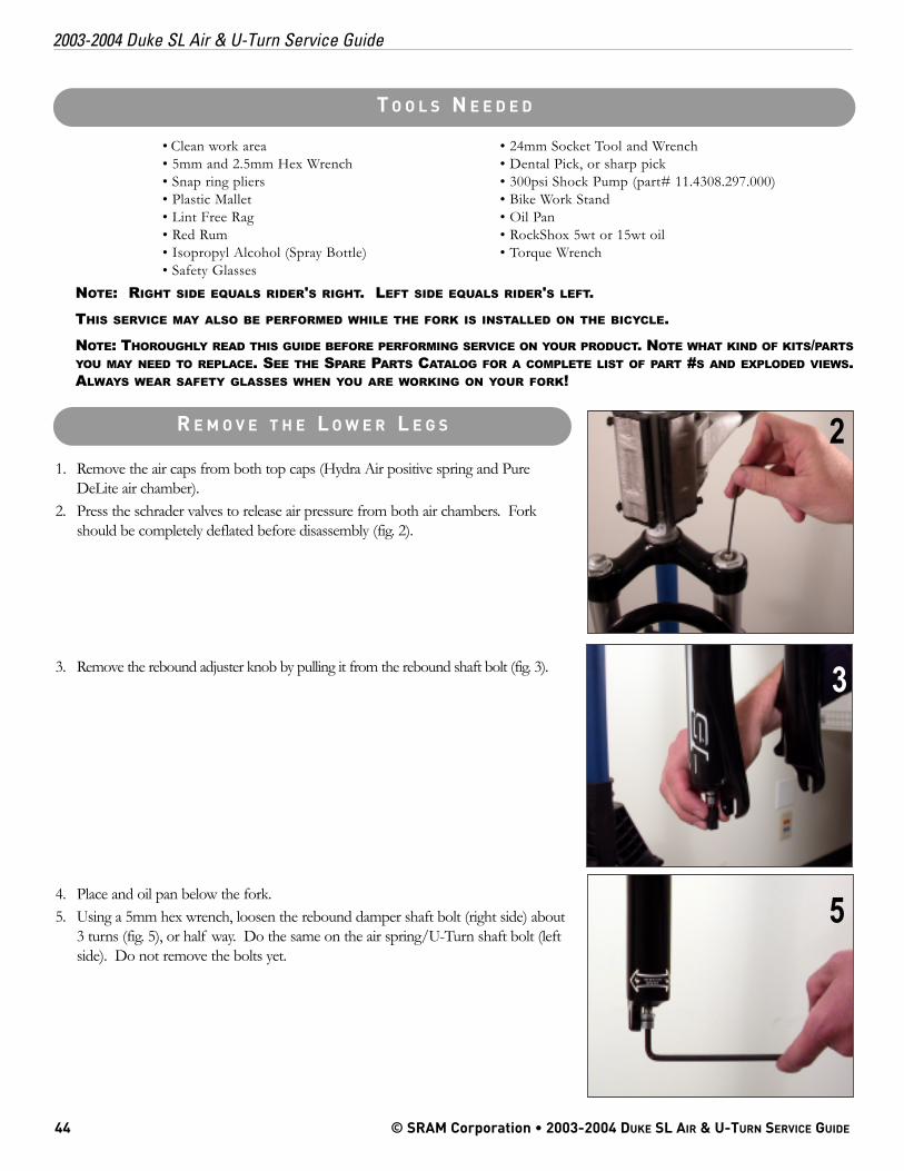
1. Remove the air caps from both top caps (Hydra Air positive spring and PureDeLite air chamber).
2. Press the schrader valves to release air pressure from both air chambers. Forkshould be completely deflated before disassembly (fig. 2).
3. Remove the rebound adjuster knob by pulling it from the rebound shaft bolt (fig. 3).
4. Place and oil pan below the fork.5. Using a 5mm hex wrench, loosen the rebound damper shaft bolt (right side) about
3 turns (fig. 5), or half way. Do the same on the air spring/U-Turn shaft bolt (leftside). Do not remove the bolts yet.
• Clean work area • 24mm Socket Tool and Wrench• 5mm and 2.5mm Hex Wrench • Dental Pick, or sharp pick• Snap ring pliers • 300psi Shock Pump (part# 11.4308.297.000)• Plastic Mallet • Bike Work Stand• Lint Free Rag • Oil Pan• Red Rum • RockShox 5wt or 15wt oil• Isopropyl Alcohol (Spray Bottle) • Torque Wrench • Safety Glasses
NOTE: RIGHT SIDE EQUALS RIDER'S RIGHT. LEFT SIDE EQUALS RIDER'S LEFT.
THIS SERVICE MAY ALSO BE PERFORMED WHILE THE FORK IS INSTALLED ON THE BICYCLE.
NOTE: THOROUGHLY READ THIS GUIDE BEFORE PERFORMING SERVICE ON YOUR PRODUCT. NOTE WHAT KIND OF KITS/PARTSYOU MAY NEED TO REPLACE. SEE THE SPARE PARTS CATALOG FOR A COMPLETE LIST OF PART #S AND EXPLODED VIEWS.ALWAYS WEAR SAFETY GLASSES WHEN YOU ARE WORKING ON YOUR FORK!
R E M O V E T H E L O W E R L E G S
T O O L S N E E D E D
5
2
3
PN 95.4308.631.000, REV. B 45
2003-2004 Duke SL Air & U-Turn Service Guide
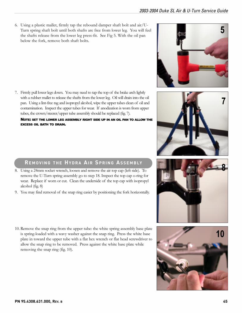
6. Using a plastic mallet, firmly tap the rebound damper shaft bolt and air/U-Turn spring shaft bolt until both shafts are free from lower leg. You will feelthe shafts release from the lower leg press-fit. See Fig 5. With the oil panbelow the fork, remove both shaft bolts.
7. Firmly pull lower legs down. You may need to tap the top of the brake arch lightlywith a rubber mallet to release the shafts from the lower leg. Oil will drain into the oilpan. Using a lint-free rag and isopropyl alcohol, wipe the upper tubes clean of oil andcontamination. Inspect the upper tubes for wear. If anodization is worn from uppertubes, the crown/steerer/upper tube assembly should be replaced (fig. 7).NOTE: SET THE LOWER LEG ASSEMBLY RIGHT SIDE UP IN AN OIL PAN TO ALLOW THEEXCESS OIL BATH TO DRAIN.
8. Using a 24mm socket wrench, loosen and remove the air top cap (left side). Toremove the U-Turn spring assembly go to step 18. Inspect the top cap o-ring forwear. Replace if worn or cut. Clean the underside of the top cap with isopropylalcohol (fig. 8)
9. You may find removal of the snap ring easier by positioning the fork horizontally.
10. Remove the snap ring from the upper tube: the white spring assembly base plateis spring-loaded with a wavy washer against the snap ring. Press the white baseplate in toward the upper tube with a flat hex wrench or flat head screwdriver toallow the snap ring to be removed. Press against the white base plate whileremoving the snap ring (fig. 10).
5
7
8
10
R E M O V I N G T H E H Y D R A A I R S P R I N G A S S E M B LY
46 © SRAM Corporation • 2003-2004 DUKE SL AIR & U-TURN SERVICE GUIDE
2003-2004 Duke SL Air & U-Turn Service Guide
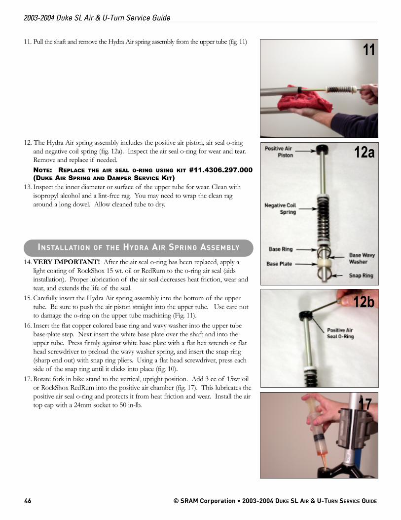
11. Pull the shaft and remove the Hydra Air spring assembly from the upper tube (fig. 11)
12. The Hydra Air spring assembly includes the positive air piston, air seal o-ringand negative coil spring (fig. 12a). Inspect the air seal o-ring for wear and tear.Remove and replace if needed.NOTE: REPLACE THE AIR SEAL O-RING USING KIT #11.4306.297.000(DUKE AIR SPRING AND DAMPER SERVICE KIT)
13. Inspect the inner diameter or surface of the upper tube for wear. Clean withisopropyl alcohol and a lint-free rag. You may need to wrap the clean ragaround a long dowel. Allow cleaned tube to dry.
14. VERY IMPORTANT! After the air seal o-ring has been replaced, apply alight coating of RockShox 15 wt. oil or RedRum to the o-ring air seal (aidsinstallation). Proper lubrication of the air seal decreases heat friction, wear andtear, and extends the life of the seal.
15. Carefully insert the Hydra Air spring assembly into the bottom of the uppertube. Be sure to push the air piston straight into the upper tube. Use care notto damage the o-ring on the upper tube machining (Fig. 11).
16. Insert the flat copper colored base ring and wavy washer into the upper tubebase-plate step. Next insert the white base plate over the shaft and into theupper tube. Press firmly against white base plate with a flat hex wrench or flathead screwdriver to preload the wavy washer spring, and insert the snap ring(sharp end out) with snap ring pliers. Using a flat head screwdriver, press eachside of the snap ring until it clicks into place (fig. 10).
17. Rotate fork in bike stand to the vertical, upright position. Add 3 cc of 15wt oilor RockShox RedRum into the positive air chamber (fig. 17). This lubricates thepositive air seal o-ring and protects it from heat friction and wear. Install the airtop cap with a 24mm socket to 50 in-lb.
11
12a
12b
INSTALLATION OF THE HYDRA AIR SPRING ASSEMBLY
17
PN 95.4308.631.000, REV. B 47
2003-2004 Duke SL Air & U-Turn Service Guide
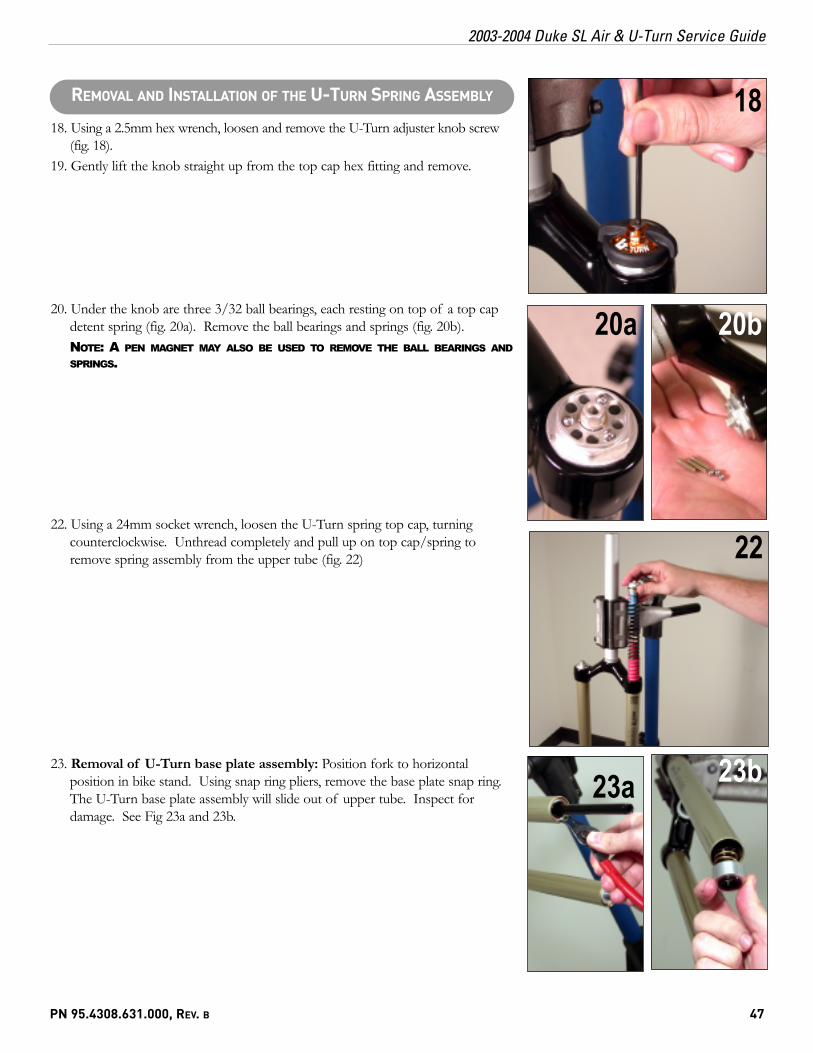
18. Using a 2.5mm hex wrench, loosen and remove the U-Turn adjuster knob screw(fig. 18).
19. Gently lift the knob straight up from the top cap hex fitting and remove.
20. Under the knob are three 3/32 ball bearings, each resting on top of a top capdetent spring (fig. 20a). Remove the ball bearings and springs (fig. 20b).NOTE: A PEN MAGNET MAY ALSO BE USED TO REMOVE THE BALL BEARINGS ANDSPRINGS.
22. Using a 24mm socket wrench, loosen the U-Turn spring top cap, turningcounterclockwise. Unthread completely and pull up on top cap/spring toremove spring assembly from the upper tube (fig. 22)
23. Removal of U-Turn base plate assembly: Position fork to horizontalposition in bike stand. Using snap ring pliers, remove the base plate snap ring.The U-Turn base plate assembly will slide out of upper tube. Inspect fordamage. See Fig 23a and 23b.
18
20b
REMOVAL AND INSTALLATION OF THE U-TURN SPRING ASSEMBLY
20a
22
23b23a
48 © SRAM Corporation • 2003-2004 DUKE SL AIR & U-TURN SERVICE GUIDE
2003-2004 Duke SL Air & U-Turn Service Guide
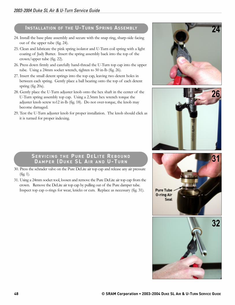
24. Install the base plate assembly and secure with the snap ring, sharp-side facingout of the upper tube (fig. 24).
25. Clean and lubricate the pink spring isolator and U-Turn coil spring with a lightcoating of Judy Butter. Insert the spring assembly back into the top of thecrown/upper tube (fig. 22).
26. Press down firmly and carefully hand-thread the U-Turn top cap into the uppertube. Using a 24mm socket wrench, tighten to 50 in-lb (fig. 26).
27. Insert the small detent springs into the top cap, leaving two detent holes inbetween each spring. Gently place a ball bearing onto the top of each detentspring (fig 20a).
28. Gently place the U-Turn adjuster knob onto the hex shaft in the center of theU-Turn spring assembly top cap. Using a 2.5mm hex wrench torque theadjuster knob screw to12 in-lb (fig. 18). Do not over-torque, the knob maybecome damaged.
29. Test the U-Turn adjuster knob for proper installation. The knob should click asit is turned for proper indexing.
30. Press the schrader valve on the Pure DeLite air top cap and release any air pressure(fig. 1).
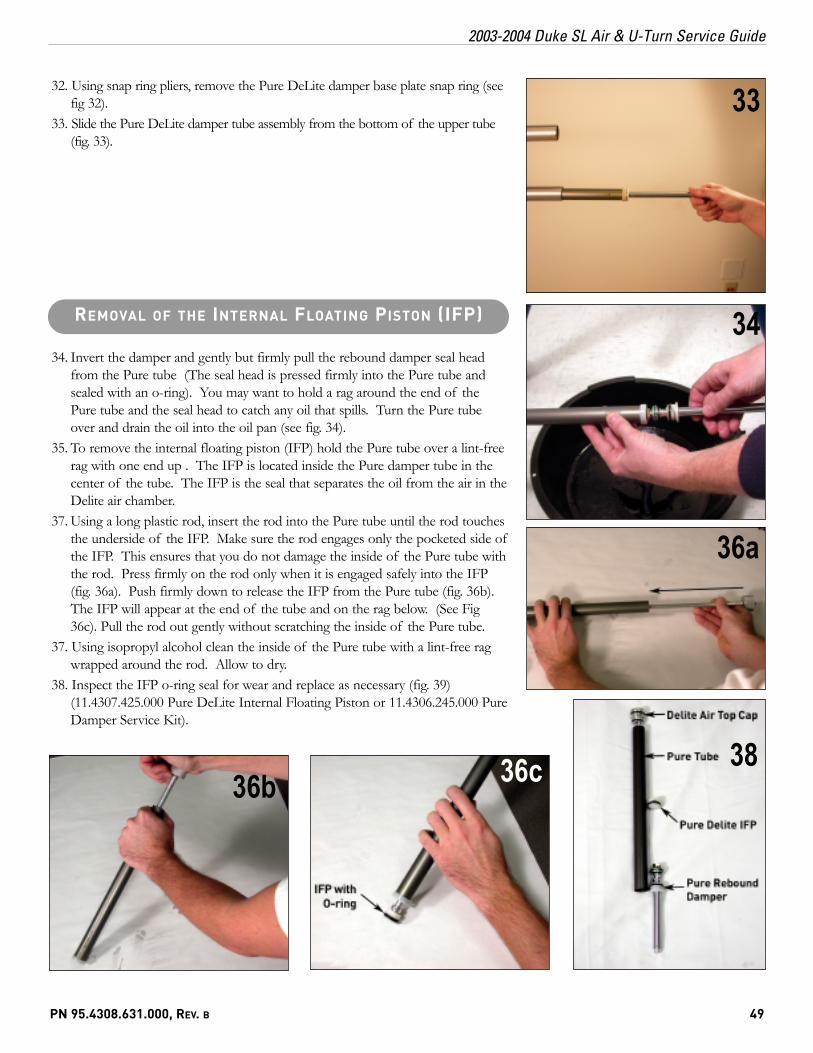
31. Using a 24mm socket tool, loosen and remove the Pure DeLite air top cap from thecrown. Remove the DeLite air top cap by pulling out of the Pure damper tube.Inspect top cap o-rings for wear, knicks or cuts. Replace as necessary (fig. 31).
26
31
INSTALLATION OF THE U-TURN SPRING ASSEMBLY 24
S E R V I C I N G T H E P U R E D E L I T E R E B O U N DDA M P E R (D U K E SL A I R A N D U-T U R N
32
PN 95.4308.631.000, REV. B 49
2003-2004 Duke SL Air & U-Turn Service Guide
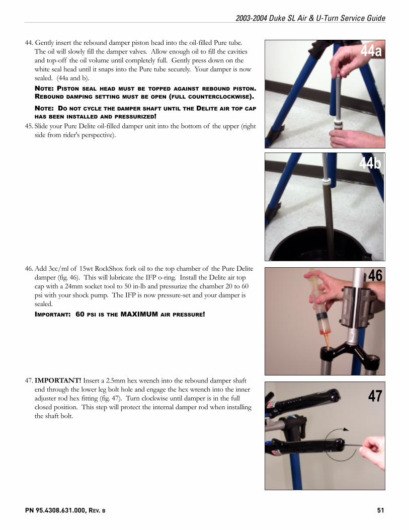
32. Using snap ring pliers, remove the Pure DeLite damper base plate snap ring (seefig 32).
33. Slide the Pure DeLite damper tube assembly from the bottom of the upper tube(fig. 33).
34. Invert the damper and gently but firmly pull the rebound damper seal headfrom the Pure tube (The seal head is pressed firmly into the Pure tube andsealed with an o-ring). You may want to hold a rag around the end of thePure tube and the seal head to catch any oil that spills. Turn the Pure tubeover and drain the oil into the oil pan (see fig. 34).
35. To remove the internal floating piston (IFP) hold the Pure tube over a lint-freerag with one end up . The IFP is located inside the Pure damper tube in thecenter of the tube. The IFP is the seal that separates the oil from the air in theDelite air chamber.
37. Using a long plastic rod, insert the rod into the Pure tube until the rod touchesthe underside of the IFP. Make sure the rod engages only the pocketed side ofthe IFP. This ensures that you do not damage the inside of the Pure tube withthe rod. Press firmly on the rod only when it is engaged safely into the IFP(fig. 36a). Push firmly down to release the IFP from the Pure tube (fig. 36b).The IFP will appear at the end of the tube and on the rag below. (See Fig36c). Pull the rod out gently without scratching the inside of the Pure tube.
37. Using isopropyl alcohol clean the inside of the Pure tube with a lint-free ragwrapped around the rod. Allow to dry.
38. Inspect the IFP o-ring seal for wear and replace as necessary (fig. 39)(11.4307.425.000 Pure DeLite Internal Floating Piston or 11.4306.245.000 PureDamper Service Kit).
33
34
36c
REMOVAL OF THE INTERNAL FLOATING PISTON (IFP)
36a
36b38

50 © SRAM Corporation • 2003-2004 DUKE SL AIR & U-TURN SERVICE GUIDE
2003-2004 Duke SL Air & U-Turn Service Guide
39. To assemble the Pure Delite damper, the IFP must first be set to a 6-inch depthinside the Pure tube. Mount a thin rod or dowel into the bicycle stand clamp orbench vice with 6 inches of exposed rod (fig. 39). The width of the end of therod should be a maximum of 8mm.
40. Apply a light coating of 15wt fork oil to the IFP o-ring for lubrication. Place theIFP on the end of the rod/dowel, with the pocketed side down (fig. 49). Thisallows the IFP to be set to a depth of 6 inches inside of the Pure tube. Placeone end of the Pure tube onto the IFP piston o-ring, and press firmly downuntil the IFP is seated inside the tube (fig. 40). Be careful, the Pure tube endsare sharp! Use a lint-free rag to protect your hands.
41. Press down until the Pure tube end is flat against the vice or bicycle stand clamp(fig. 41). Pull the Pure tube up and off of the rod/dowel. The IFP is nowseated firmly inside the tube at a 6-inch depth.
42. Before installing the Pure rebound damper assembly, remove the white seal headassembly from the rebound damper shaft. The seal head includes an outer o-ring oil seal and an inner shaft o-ring oil seal. Inspect and replace if damaged orworn using the Pure Damper o-ring service kit (part# 110-006245-00). Reinstallthe seal head by sliding it over the rebound damper shaft.NOTE: LUBRICATE THE INNER REBOUND SHAFT O-RING WITH A SMALLAMOUNT OF OIL BEFORE INSTALLATION.
43. Holding the Pure tube over an oil pan, with the pocketed side of the IFP facingdown (rounded side facing up), fill the tube until completely full with 15wtRockShox fork oil.TIP: FOR QUICKER REBOUND DAMPING, OR IN COLDER WEATHER, YOU MAYSUBSTITUTE 5 OR 10WT OIL FOR THE STOCK 15WT. LIGHTER WEIGHTDAMPING OIL ALSO DECREASES THE AMOUNT OF COMPRESSION DAMPING INTHE PURE DELITE DAMPER.
41
39ASSEMBLING THE PURE DELITE DAMPER: SETTING THEIFP DEPTH INSIDE THE PURE TUBE
40
PN 95.4308.631.000, REV. B 51
2003-2004 Duke SL Air & U-Turn Service Guide
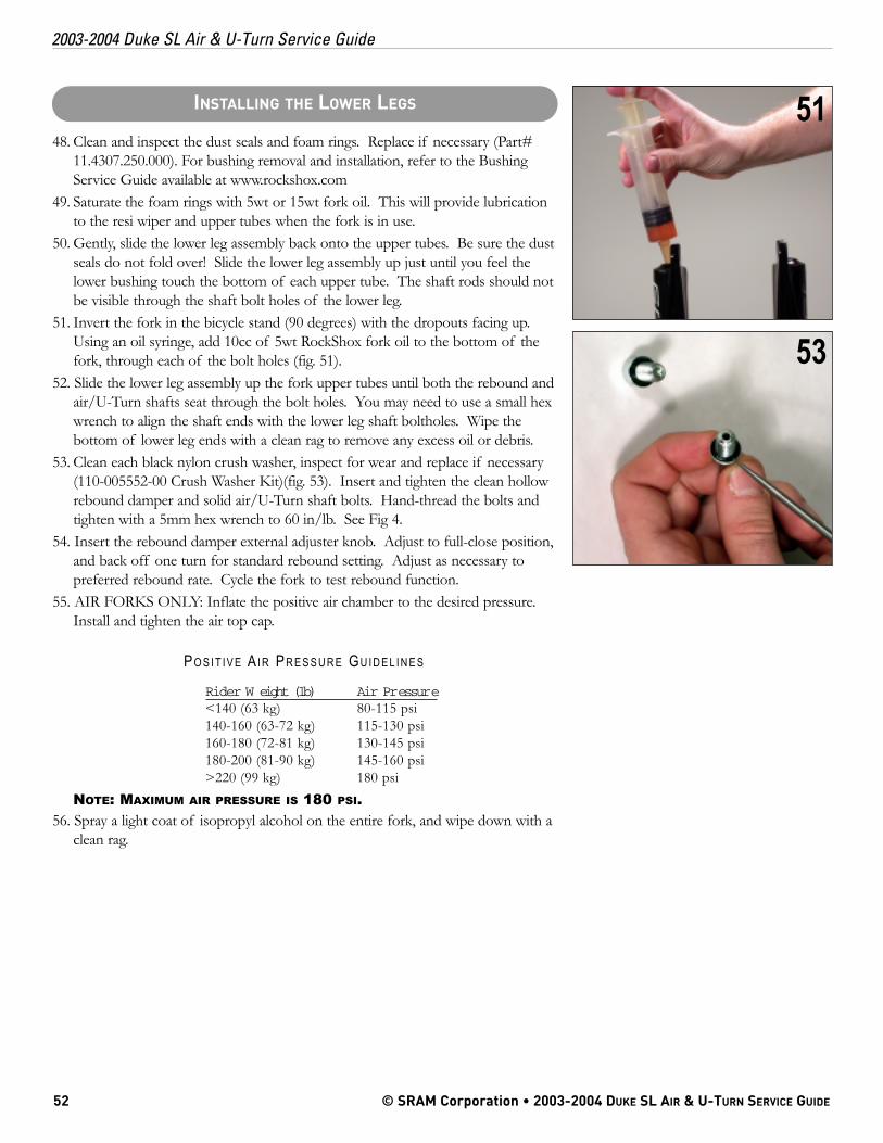
44. Gently insert the rebound damper piston head into the oil-filled Pure tube.The oil will slowly fill the damper valves. Allow enough oil to fill the cavitiesand top-off the oil volume until completely full. Gently press down on thewhite seal head until it snaps into the Pure tube securely. Your damper is nowsealed. (44a and b).NOTE: PISTON SEAL HEAD MUST BE TOPPED AGAINST REBOUND PISTON.REBOUND DAMPING SETTING MUST BE OPEN (FULL COUNTERCLOCKWISE).
NOTE: DO NOT CYCLE THE DAMPER SHAFT UNTIL THE DELITE AIR TOP CAPHAS BEEN INSTALLED AND PRESSURIZED!
45. Slide your Pure Delite oil-filled damper unit into the bottom of the upper (rightside from rider's perspective).
46. Add 3cc/ml of 15wt RockShox fork oil to the top chamber of the Pure Delitedamper (fig. 46). This will lubricate the IFP o-ring. Install the Delite air topcap with a 24mm socket tool to 50 in-lb and pressurize the chamber 20 to 60psi with your shock pump. The IFP is now pressure-set and your damper issealed.IMPORTANT: 60 PSI IS THE MAXIMUM AIR PRESSURE!
47. IMPORTANT! Insert a 2.5mm hex wrench into the rebound damper shaftend through the lower leg bolt hole and engage the hex wrench into the inneradjuster rod hex fitting (fig. 47). Turn clockwise until damper is in the fullclosed position. This step will protect the internal damper rod when installingthe shaft bolt.
44a
44b
46
47
52 © SRAM Corporation • 2003-2004 DUKE SL AIR & U-TURN SERVICE GUIDE
2003-2004 Duke SL Air & U-Turn Service Guide
48. Clean and inspect the dust seals and foam rings. Replace if necessary (Part#11.4307.250.000). For bushing removal and installation, refer to the BushingService Guide available at www.rockshox.com
49. Saturate the foam rings with 5wt or 15wt fork oil. This will provide lubricationto the resi wiper and upper tubes when the fork is in use.
50. Gently, slide the lower leg assembly back onto the upper tubes. Be sure the dustseals do not fold over! Slide the lower leg assembly up just until you feel thelower bushing touch the bottom of each upper tube. The shaft rods should notbe visible through the shaft bolt holes of the lower leg.
51. Invert the fork in the bicycle stand (90 degrees) with the dropouts facing up.Using an oil syringe, add 10cc of 5wt RockShox fork oil to the bottom of thefork, through each of the bolt holes (fig. 51).
52. Slide the lower leg assembly up the fork upper tubes until both the rebound andair/U-Turn shafts seat through the bolt holes. You may need to use a small hexwrench to align the shaft ends with the lower leg shaft boltholes. Wipe thebottom of lower leg ends with a clean rag to remove any excess oil or debris.
53. Clean each black nylon crush washer, inspect for wear and replace if necessary(110-005552-00 Crush Washer Kit)(fig. 53). Insert and tighten the clean hollowrebound damper and solid air/U-Turn shaft bolts. Hand-thread the bolts andtighten with a 5mm hex wrench to 60 in/lb. See Fig 4.
54. Insert the rebound damper external adjuster knob. Adjust to full-close position,and back off one turn for standard rebound setting. Adjust as necessary topreferred rebound rate. Cycle the fork to test rebound function.
55. AIR FORKS ONLY: Inflate the positive air chamber to the desired pressure.Install and tighten the air top cap.
PO S I T I V E AI R PR E S S U R E GU I D E L I N E S
Rider W eight (lb) Air Pressure<140 (63 kg) 80-115 psi140-160 (63-72 kg) 115-130 psi160-180 (72-81 kg) 130-145 psi180-200 (81-90 kg) 145-160 psi>220 (99 kg) 180 psi
NOTE: MAXIMUM AIR PRESSURE IS 180 PSI.56. Spray a light coat of isopropyl alcohol on the entire fork, and wipe down with a
clean rag.
51INSTALLING THE LOWER LEGS
53