Embed Size (px)
Citation preview
7/14/2019 Aikido All One
http://slidepdf.com/reader/full/aikido-all-one 1/18
Aikido Stereo 9-Pin PCB
USER GUIDE
IntroductionOverviewSchematicsRecommended ConfigurationsTube Lists Assembly Instructions
lass areW AUDIO DESIGN
FEB 25 2009
All
In

7/14/2019 Aikido All One
http://slidepdf.com/reader/full/aikido-all-one 2/18
GlassWare Audio Design
DANGER!This PCB holds a high-voltage power supply; thus, a realand possibly—lethal shock hazard exists.
Ideally, a variac should be used to slowly power up theregulator, as it is better to have a mis-oriented electrolyticcapacitor or a mis-located resistor blow at low voltages,rather than at high voltages. Remember that the danger increases by the square of the voltage; for example, 200volts is four times more dangerous than 100 volts and 400volts is sixteen times more dangerous.
Once the power supply is powered up, be cautious at alltimes. In fact, even when the power supply is disconnectedor shut down, assume that power-supply capacitors will haveretained their charge and, thus, can still shock. If you are notan experienced electrical practitioner, before attaching thetransformer windings to the board, have someone who iswell-experienced in electronics review your work.
There are too few tube-loving solder slingers left; we cannot
afford to lose any more.
AUDIO DESIGNwww.glass-ware.com
www.tubecad.com
Copyright © 2009 All Rights Reserved
GlassWare

7/14/2019 Aikido All One
http://slidepdf.com/reader/full/aikido-all-one 3/18
GlassWare Audio Design
Warning! This PCB contains ahigh-voltage power supply; thus, a real and lethal shock hazardexists. Once the power transformer is attached, be cautious at all times. In fact, alwayassumethat the high voltagecapacitors will have retained their charge even after thpower supply has been disconnected or shut down. If you are not an experiencedelectrical practitioner, before applying the AC voltage have someone who iexperienced review your work. There are too few tube-loving solder slingers left; wcannot afford to lose any more.
Overview Thank you for your purchase of the TCJ Aikido All in One 9-pin stereo PCB. This FR4 PCB is extra thick, 0.094 inches (inserting and pulling tubes from their sockets won’bend or break this board), double-sided, with plated-through heavy 2oz copper traces.In addition, the PCB is lovingly and expensively made in the USA. The boards are 6.5by 6 inches, with five mounting holes, which helps to prevent excessive PCB bendinwhile inserting and pulling tubes from their sockets.
Each PCB holds two Aikido line-stage amplifiers; thus, one board is all that is neededfor stereo unbalanced use (or one board for onechannel of balanced amplification). Bincluding the necessary components for the heater and high voltage B+power supplieon the PCB, the All in One board makes building a standard-setting line stagamplifier a breeze. This assembled board with a chassis, volume control, selectoswitch, power transformer, and a fistful of RCA jacks is all that is needed.
PCB FeaturesB+and Heater Power Supplies On theAll in One board, two power supplies reside,one for the high-voltage B+ for the tubes and a low-voltage power supply for thheaters. The high-voltage power supply uses an RC filter to smooth away ripple, whilthe low-voltage power supply uses a voltage regulator to provide a stable and noise-frevoltage output. The power supplies require an external power transformer(s) with twsecondary windings.
Redundant Solder Pads This board holds two sets of differently-spaced solder pads foeach critical resistor, so that radial and axial resistors can easily be used (radial bulk-foilresistors and axial film resistors, for example). In addition, most capacitor locationfind many redundant solder pads, so wildly differing-sized coupling capacitors can bplaced neatly on the board, without excessively bending their leads.
Multiple Heater Arrangements TheAll i n One PCB allows either 6.3V or 12.6V heatepower supplies to be used; and 6V tubes, such as the 6CG7, can be used with 12Vtubes, such as the 12BH7 (if a 12V heater voltage is used).
Power-Supply-Decoupling Capacitors The All in One PCB provides space for two setof capacitors to decouple both Aikido gain stages from the B+connection and eachother. This arrangement allows a large-valued electrolytic capacitor and small-valuedfilm capacitor to be used in parallel, while a series voltage-dropping resistor completethe RC filter. In place of the series resistor, an off-board chokecan be used for eachchannel.
A @

7/14/2019 Aikido All One
http://slidepdf.com/reader/full/aikido-all-one 4/18
2
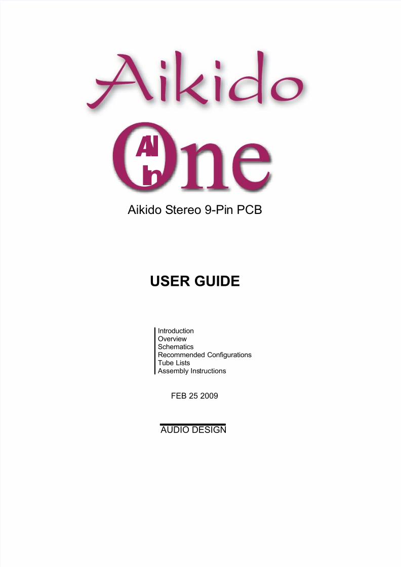
Th Aikido amplifier delivers the sonic goods. It offers low distortion, low outpuimpedance, a great PSRR figure, and feedback-free amplification. The secret to itsuperb performance—despite not using global feedback—lies in its internal symmetry,which balances imperfections with imperfections. As a result, the Aikido circuit workat least a magnitude better than the equivalent SRPP or grounded-cathode amplifier.
Aikido AmplifierB+
Rk
Rk
in
out
R2
R1
Rk
Rk
C
12AX7
Rg
Rgs
Rgs 12AU7
12AX7 12AU7
Introduction to the Aikido
Universal Topolog In the schematic abov , the triodes are specified as an examplonly. Although they would never fit on the printed circuit board (PCBs), 211 and 84triodes could be used to make an Aikido amplifier. The circuit does not rely on thestriodes or any other specific triodes to work correctly. It’s thetopology, not the tubethat make the Aikido special. (Far too many believethat a different triode equalsdifferent topology; it doesn't. Making this mistake would be like thinking that thessential aspect of being a seeing-eye dog rested in being a Golden Lab.)
Low Distortion For example, the Aikido circuit produces far less distortion thancomparable circuits by using the triode’s own nonlinearity against itself. The triode inot as linear as a resistor so, ideally, it should not see a linear load, butcorresponding, complementary, balancing non-linear load. An analogy is found insomeone needing eyeglasses; if the eyes were perfect, then perfectly flat (perfectllinear) lenses would be needed, whereas imperfect eyes need counterbalancing lense(non-linear lenses) to see clearly. Now, loading a triode with the same triode—undethe same cathode-to-plate voltage and idlecurrent and with the same cathode resistorworks well to flatten the transfer curve out of that triode.
PSRR The Aikido circuit sidesteps power supply noise by incorporating the noise intits normal operation. The improved PSRR advantage is important, for it greatlunburdens the power-supply. With no tweaking or tubeselecting, you should easily bable to get a -30dB PSRR figure (a conventional grounded-cathode amplifier with thsametubes and current draw yields only a -6dB PSRR); and with some tweaking oresistor R1’s value, -60dB—or more—is possible. Additionally, unless regulated powesupplies are used for the plate and heater, these critical voltages will vary as the poweline’s voltage falls and climbs with your house’s and neighbors’ house’s use, usuallthrowing the supposedly fixed wall-voltage askew. Nevertheless, the Aikido amplifiewill still function flawlessly, as it tracks these voltage changes symmetrically.
Aikido Stereo All-In-One 9-Pin PCB

7/14/2019 Aikido All One
http://slidepdf.com/reader/full/aikido-all-one 5/18
GlassWare Audio Design
Age Toleran Remembe, tubes are not yardsticks, being more like car tire thewear out. Just as a tire’s weight and diameter decrease over time, so does a tube’sconductance. In other words, a fresh 12AX7 is not the same as that same 12AX7 after2,000 hours of use. But as long as the two triodes within the 12AX7 agein the samway—which they are inclined to do—the Aikido amplifier will always bias upcorrectly, splitting the B+voltagebetween thetriodes.
No Negative Feedback Loop The Aikido topology does not use any negativfeedback, other than the local degenerative feedback because of the unbypassedcathode resistors in the input stage and the active load presented by the bottotriode of the output stage. In fact, the Aikido topology makes use of feedforwardnoise canceling at the output. Unlike negative feedback that has to wait untilsomething goes wrong beforeit can work to undo the damage, feedforward feedbacanticipates what will go wrong beforeit does. It is proactive, not reactive, to borrothe terms of pop-psychology.
The Aikido circuit eliminates power-supply noise from its output, b
injecting the same amount of PS noise at theinputs of thetop and bottom tubes inthe two-tube cathode-follower circuit. Since both of these signals are equal inamplitude and phase, they cancel each other out, as each triode sees an identicalincrease in platecurrent—imagine two equally strong men in a tug of war contest. So,shouldn’t resistors R1 and R2 sharethe same value, thereby also splitting the powersupply noise at 50%? No. If triode did not present a low plate resistance, then th50% ratio would apply. Because of the low rp, the correct relationship betweenresistors R1 and R2 is given by the following formula:
R1 = R2[(mu - 2)/(mu + 2)]
Low Output Impedance The Aikido topology uses a modified cathode follower
circuit as the output stage. Cathode followers are famous for providing lodistortion and low output impedances, but no voltage gain. This modified cathodfollower scrubs away the power-supply noise from its output and providescomplementarily non-linear load for the top triode’s cathode. The top triode’capacitor resistor is in series with the output, so its resistance must be added to thcathode follower output impedance. Had the output connection been taken from thtop triode’s cathode, then the output impedance would be slightly lower, but thsymmetry would be broken and the PSRR enhancement would be lost.
GainCalculating the gain from an Aikido amplifier is easy, as it roughly equals hal
the mu of theinput triode used. The gain from a simple grounded-cathode amplifier(with an un-bypassed cathode resistor) is
Gain = muRa/[Ra + (mu + 1)Rk + rp]
In the Aikido, the resistance presented by the top tube and its cathode resistor iR' =(mu +1)Rk +rp. So if you substituteR' for Ra in theaboveequation andsimplify you get
Gain = mu[(mu + 1)Rk + rp ] / [(mu + 1)Rk + rp + (mu + 1)Rk + rp] = mu/2
Of coursethere is a slight loss though theAikido’s modified-cathode-follower outputstage, whose gain usually falls between 0.93 to 0.98.

7/14/2019 Aikido All One
http://slidepdf.com/reader/full/aikido-all-one 6/18
GlassWare Audio Design
Heater Issues The All in One PCB holds the heater raw power supply and voltage regulator. Thregulator uses the LD1085 low-dropout adjustable voltageregulator. The regulator canbe set to an output voltage between 6V to 25V, but the assumption is that a 12Vdoutput voltage will be used for the heaters, so that 6.3V heater tubes (like the 6FQ7 and6DJ8) or 12.6V tubes (likethe 12AU7 or 12AX7) can be used. Both voltage types can
be used exclusively, or simultaneously; for examplea 6GC7 for the input tube and a12BH7 for the output tube. Thus, if the input tubes (V1 and V2) are 6CG7s and thoutput tubes (V3 and V4) are12BH7s and the heater regulator output voltage is 12Vdc,then use jumpers J2, J4, and J5.
Although the preferred power supply voltageis 12V, a 6Vdc (or 6.3Vdc) heater powesupply can be used with the PCB, as long as all the tubes used have 6.3V heaters (or5V or 8V or 18V power supply can be used, if all thetubes share the same 5V or 8V o18V heater voltage). Just use jumpers J1, J3, J4, and J6 only. Note: Perfectly good tubewith uncommon heater voltages can often be found at swap meets, eBay, and surplu
stores for a few dollars each. Think outside 6.3V box.
AC Heaters An AC heater power supply (6.3V or 12.6V) can be used, if the heaterectifiers, power supply capacitors, and regulator are all left off the board. This is noin the least recommended, as the high-current AC voltage will introduce hum andcompromisethe bass reproduction.
54
V1
J1
+H
-H
Filament Jumper Wire Schedule
Tubes V1 & V2 V3 & V4If tubes are 6.3V: J2 only J5 only
If 12.6V: J1 & J3 J4 & J6
With a 12.6V PS
V2
5 4
J2 J3
54
V3
J4
V4
5 4
J5 J6 C16Tubes V1 & V2 V3 & V4All tubes = 6.3V: J1 & J3 J4 & J6
If 12.6V: Cannot be used with 6.3V PS
With a 6.3V PS
AC
LD1085
Adj
InOut
Heater +
Heater -
A C
C13
C15
C14
R20D1
D2
D10 C10D9C9
D12 C12D11C11
R19
{

7/14/2019 Aikido All One
http://slidepdf.com/reader/full/aikido-all-one 7/18
GlassWare Audio Design
The heate’s PS reference bia voltage to target is one quarter of the B-plus voltage thathe Aikido’s tubes use, not the initial raw B-plus voltage at the high voltage rectifiers
This means that resistors R17 and R18 values must be experimentally selectedAlt rnatively, you might experiment with floating the heater power supply, b“grounding” the heater power supply via only a 0.1µF film or ceramic capacitor,leaving resistors R17 and R18 off the board. The capacitor will charge up through thleakage current between heater and cathodes. Not only is this method cheap, it is oftequite effective in reducing hum with certain tubes.
DCHeater
Regulator
300k1W
82k1W
B+
Raw B+
4.7
0.1µF250V
AC R17
R18
Final B+
4
Since one triode stands atop another, the heater-t cathode voltage experienced differsbetween triodes. The safest path is to reference the heater power supply to a voltagequal to one fourth the B+voltage; for example, 75V, when using a 300V powersupply. The ¼ B+ voltage ensures that both top and bottom triodes see the sammagnitude of heater-to-cathode voltage. The easiest way to set this voltage relationshipup is thefollowing circuit:
Heater Voltage =
R19 =R20 =
D9, 10, 11, 12 =D1*, 2* =
C9, 10, 11, 12 =C13 =C14 =C15 =
Regulator =Vac Input =
6V 6.3V 8V 12V 12.6V
470 499 670 1.07k 1.13k124 same same same same
MUR410G " " " "1N4007 " " " "
1000pF - 50V " " " "10kµF - 10V* " "1kµF - 10V* " " " "1kµF - 10V* " " " "
LD1085, LM317, LM350, LT10857-8Vac @ 5A for 6.3Vdc12-12.6Vac @ 2.5A for 12Vdc or 12.6Vdc
Typical Part Values
Resistors R19 and R20 set theheate voltage regulator’s output voltage. The formula i
Thus, using a 125-ohm resistor for R20 and a 2.4k resistor in R19 position, the outputwill climb to 25.2Vdc. See the values table above.
V0
= 1.25(1 + R19
/ R20
)
( )

7/14/2019 Aikido All One
http://slidepdf.com/reader/full/aikido-all-one 8/18
GlassWare Audio Design
B-plus Power Supply The high voltage B-plus power supply resides on the Aikido All in One PCB. Itcontains a full-wave bridge rectifier circuit and reservoir capacitor, which is thenfollowed by an RC-smoothing filter. The high voltage power transformer is external tothe PCB and can be mounted in, or outside, the chassis that houses the PCB.
The optimal B-plus voltage depends on the tubes used. For example, 6GM8s (ECC86)can be used with a low 24V power supply, while 6DJ8s work better with a 150V to240V B-plus voltage; 6CG7s, 200V to 300V. The sky is not the limit here, as the powersupply capacitors and the heater-to-cathodevoltage set an upward limit of about 350Vfor the power supply voltage after the rectifiers and about 300V at the tubes after thRC filter. Resistors R12a and R12b are in parallel, so that greater dissipation and valuselection are possible; for example, treat two 10k/3W resistors as one 5k/6W resistor.Resistor heat equals I² x R (and V²/R); for example, 20mA and 5k will dissipate2W.See pages 13 and 14 for more information.
Bear in mind, there is a practical limit to how large a power-supply noise signal can bnulled at the Aikido’s output. So there are several goals that work against each other:we want the largest voltage-dropping resistor value possible, as it reduces the ripplappearing at the tubes’ power supply connection; we want the lowest raw B-plus voltagpossible, as it will allow a larger-valued reservoir capacitor and limit the heater-to-cathode voltage; and we want the highest plate voltage possible for the tubes, as itmakes for better sound. We cannot have it all. A typical 250V capacitor is much morvolumetrically efficient than a 400V capacitor. Thus, running a lower B-plus voltagallows us to increase greatly the capacitance in the power supply. Running lightercurrent allows us to maximize resistor R12’s (combined) value.
C4 =C5 =C7 =C8 =
D5-8 =
R12 =R13-16 =
R17 =R18 =
0.1µf to 1µF* (0.33µF 630V)47µF to 470µF* (150µF 400V)33µF to 100µF* (33µF 450V)0.01µF to 0.47µF >= 100V
*Voltage depends ontransformer used; all mustexceed the B+ voltage.
1N5402 (MUR410G)
100 to 20k10 1W300k 1W50k to 100k 1W
() Parentheses denote recommended values
Typical Part Values
D5
D7
D6
D8
AC
R13 R14
R15 R16
C7
R17
R18C8
B+
to Heater -
R12a
R12aC5C4
C5C4
J7
Left
Right
R12b
R12b

7/14/2019 Aikido All One
http://slidepdf.com/reader/full/aikido-all-one 9/18
GlassWare Audio Design
B+ Voltage =Heater Voltage =
R1,11 =R2,5,8 =
R3,4 =R6,7 =R10 =R9 =
C1,2 =C3 =C4 =C5 =C6 =C7 =C8 =
0.01-0.33µF (optional) Same Same Same0.1 - 4µF* Film or Oil " " "0.01 - 1µF* Film or Oil " " "100µF* " " "0.1 - 1µF* Film or Oil " " "33µF-100µF, 200V-450V " " "0.1µF 160V(optional) '' " ''
*Voltage rating must equal or exceed B+ voltage
(input) V1, V2 =
(output) V3, V4=
6CG7, 6FQ7 6CG7, 6FQ7 12AU7, 5814, 5963, 12AU7, 5814, 5963,6189, ECC82 6189, ECC82
6DJ8, 6922, 6CG7, 6FQ7 12AU7, 5814, ECC82 12BH7, ECC997308, E88CC
*High-quality resistors essential in this position. All resistors 1/2W or higher
Typical Part Values () Parentheses denote recommended values
Power Transformer(s) The Aikido All in One PCB requires a power transformer(s) to energize its two powesupplies. The heater power supply power transformer must offer at least 1.8 timemore current than the heaters will draw. For example, four 12AU7s will draw [email protected], so the heater power transformer must be able to sustain an AC 1.08A currendraw. In addition, with sine waves, the AC voltage equals the peak voltage divided b
the square root of 2, i.e. 1.414. Thus, a 10Vac sinewave peaks at 14.14V; a 6.3Vac,8.9V. In other words, a sinewavethat peaks at 14.14V will produce the same amounof heat in a resistance as a 10Vdc voltage source would produce in the samresistance; thus, we label the 14.14Vpk sine wave as being 10Vac. Thus, in order to gethe 16Vdc a 12.6V heater voltage regulator requires an input voltage equal to sum o16V and therectifier loss (about 2V) divided by 1.414, which is roughly 12.6Vac.
The high voltage power transformer must also follow the same rules. Thus, to achiev300V of raw DC voltage, thetransformer primary must deliver (300V +2V) / 1.414,or about 214Vac. And if 50mA is required, the power transformer must be rated fo50mA x 1.8, or about 90mA. Such a transformer VA rating would equal 33VA.
A center-tapped primary can be used; just leave D7, D8, R15, and R16 off the board,then attach the center-tap to D7 or D8’s bottom eyelet, where its label appears.
Configuring the PCB as a Line Amplifier The Aikido topology makes a perfect line amplifier, as it offers low distortion, looutput impedance, and excellent power-supply noise rejection—all without a globalfeedback loop. For guidance on part values, look at the page 12, which lists differentubedesign examples.
6CG7 & 6DJ8 6CG7 & 6CG7 12AU7 & 12AU7 12AU7 & 12BH7
100V - 250V (200V) 200V - 300V (300V) 200V - 300V (250V) 200V - 300V (300V)6.3V or 12.6V 6.3V or 12.6V 12.6V 12.6V
1M Same Same Same270 - 1k (300)* " " "100 - 1k (390 5mA)* 200 - 1k (1k 4.5mA)* 100 - 1k (680 5.5mA)* 100 - 1k (1k 5.5mA)*200 - 330 (200 10mA)* 270 - 680 (470)* 180 - 470 (200)* 200 - 470 (523)*87.5k 83.2k 80k 79.3k100k Same Same Same

7/14/2019 Aikido All One
http://slidepdf.com/reader/full/aikido-all-one 10/18
GlassWare Audio Design
Tube SelectionUnlike 99.9% of tube circuits, the Aikido amplifier defines a new topology withoufixed part choices, not an old topology with specified part choices. In other words, anAikido amplifier can be built in a nearly infinite number of ways. For example,12AX7 input tube will yield a gain close to 50 (mu/2), which would be suitablefor aSE amplifier’s input stage; a 6FQ7 (6CG7) input tube will yield a gain near 10, whichwould be excellent for a line stage amplifier; the 6DJ8 or 6H30 in the output stagwould deliver a low output impedance that could drive capacitance-laden cables. Iother words, the list of possible tubes is a long one: 6AQ8, 6BC8, 6BK7, 6BQ7, 6BS86DJ8, 6FQ7, 6GC7, 6H30, 6KN8, 6N1P, 12AT7, 12AU7, 12AV7, 12AX7, 12BH7,12DJ8, 12FQ7, 5751, 5963, 5965, 6072, 6922, E188CC, ECC88, ECC99…The onlstipulations are that the two triodes within the envelope be similar and that the tubconforms to the 9A or 9AJ base pin-out. Sadly, the 12B4 and 5687 cannot be usewith this PCB.
Internal Shields
If the triode’s pin 9 attaches to an internal shield, as it does with the 6CG7 and 6DJ8,then capacitors C1 and C2 can be replaced with a jumper, which will ground thshield. However, using the capacitors rather than jumpers will also ground the shiel(in AC terms) and allow swapping in triodes whose pin-9 attaches to the center tap oits heater, such as the12AU7.
Cathode Resistor Values The cathoderesistor and plate voltage set the idle current for the triode: the larger thvalue of the resistor, less current; the higher the plate voltage, more current. In general,high-mu triodes require high-value cathode resistors (1-2K) and low-mu triodes requirlow-valued cathode resistors (100-1k). The formula for setting the Iq is an easy one:
Iq = B+/2(rp + [mu + 1]Rk)
So, for example, a 6CG7 in an Aikido circuit with a B+voltage of +300V and 1cathode resistors will draw 300/2(8k +[2 +1]1k) amperes of current, or 2.6mA. Irecommend 680 to 1.1k for the12AX7, 5751, 6072 tubes and 100 to 330 for the6DJand 6N1P tubes. Other tubes, such as the 6CG7, 12AT7, 12AU7, 12BH7 work wellwith 470-ohm cathode resistors. Because the cathode resistors see so little voltagdifferential, 1/2W resistors can readily be used. Be sureto see the tube chart on the laspage for many illustrations.
Coupling-Capacitor Values The bigger in value the coupling capacitor, the lower the -3dB high-pass cornefrequency will be. Theformula is as follows:
Frequency = 159155/C/R
where C is in µF. For example, with a1µF coupling capacitor and a power amplifiewith an input impedance of 47k, the corner frequency would be 3.5Hz. Thehigher thload impedance, the lower the corner frequency. The coupling capacitor voltage ratinmust at least equal the B+voltage, for safety’s sake. Although pads weren’t providefor bypass capacitors for the coupling capacitors, a small bypass capacitor can bsolder on the bottom of the PCB, using two of the redundant solder pads.

7/14/2019 Aikido All One
http://slidepdf.com/reader/full/aikido-all-one 11/18
GlassWare Audio Design
Assembly & Testing
Assembly Cleanliness is essential. Before soldering, be sureto clean both sides thPCB with 90% to 99% isopropyl alcohol. Do not use dull-looking solder; soldeshould shine. If it doesn’t, first clean away the outer oxidation with some steel woolor a copper scouring pad. If theresistor leads look in the least gray, clean away th
oxidation with either steel wool or a wiresniper’s sharp edges. Admittedly, with neresistors and a fresh PCB, such metal dulling is rare; but if the parts have sat in youcloset for a year or two, then expect a good amount of oxidation to have developed.
First, solder all the small diodes in place, and then solder the resistors, rectifierscapacitors, and heatsinks. Be consistent in orienting the resistors; keep all thtolerance bands on the resistor’s body at the right side as you face the resistostraight on. This will pay dividends later, if you need to locate asoldered a resistor ithe wrong location. Because the board is double sided, with traces and pads on eacside, it is easier to solder the resistors from their top side. It is often easier to attacthe LD1085 (heater regulator) to its heatsink first (using theheatsink hardware kit)
and then to solder both theheatsink and regulator to the PCB at once. As the PCB iso overbuilt, it is extremely difficult to remove an incorrectly placed part. Be sure tconfirm all the electrolytic capacitor orientations, as a reversed polarized capacitocan easily vent (or even explode) when presented with high-voltage. Confirm twicsolder once.
Testing Before testing, visually inspect the PCB for breaks in symmetry between lef and right sides. Wear safety eye goggles, which is not as pantywaist a counsel as isounds, as a venting power-supply capacitor will spray hot caustic chemicals. Makehabit of using only one hand, with the other hand behind your back, while attachinprobes or handling high-voltage gear, as a current flow across your chest can result indeath. In addition, wear rubber-soled shoes and work in dry environment.Remember, safety first, second, and last.
1. Attach only the heater power supply’s transformer winding, leaving thhigh-voltage transformer leads unattached and electrical tape shrouded, witno tubes in their sockets.
2. Use a variac and slowly bring up the AC voltage, while looking for smokor part discoloration or bulging.
3. Measure the heater regulator’s output voltage without and with a load. Ithe heater regulator fails to regulate, try either lowering the heater voltagetad, for example 12V instead of 12.6V, as the 0.6V difference might b
enough to bring the regulator back into regulation.4. Next, power down theheater regulator and attach thehigh-voltage windingand insert the tubes in their sockets.
5. Attach the transformer to a variac and slowly bring up the AC voltage.6. Measure the voltage across ground and B-plus pads in the center of th
PCB; then measure the voltage across capacitors, C4 & C5. If the twchannels differ by more than 10Vdc, try switching tubes from one channelto the other. If the imbalance does not follow the tubes, there is a problemprobably a misplaced part.
Only after you are surethat both heater and B-plus power supplies are working wellshould you attach the lin stage amplifier to a power amplifie.

7/14/2019 Aikido All One
http://slidepdf.com/reader/full/aikido-all-one 12/18
GlassWare Audio Design
Grounding TheAll in One PCB holds a star ground at its center. Ideally, this will be the onlcentral ground in the line-stage amplifier. Ground loops, however, are extremely easto introduce. For example, if theRCA jacks are not isolated from the chassis, then thtwisted pair of wires that connect the PCB to the jacks will each define a ground loop(as will jumper J7, which bridges the PCB’s ground to the chassis). The solution i
either to isolatethe jacks or use only a single hot wirefrom jack to PCB (the wire canbe shielded, as long as the shield only attaches at one end). Thus, the best plan is tplan. Before assembling the line-stage amplifier, stop and decidehow thegrounding igoing to be laid out, then solder.
Three different schools of thought hold for grounding a piece of audio gear. TheOld-School approach is to treat the chassis as the ground; period. Every groundconnection is made at the closest screw and nut. This method is the easiest to followand it produces the worst sonic results. Steel and aluminum are poor conductors.
The Semi-Star ground method uses several ground “stars” that are often called spurs,which then terminate in a single star ground point, often a screw on the chassis. Thisystem can work beautifully, if carefully executed. Unfortunately, often too much iincluded in each spur connection. For example, all the input and output RCA jackshareground connection to a long run of bare wire, which more closely resemblessnake than a spur ground. In other words, the spurs should not be defined jusphysical proximity, but signal transference. Great care must beexercised not to doublground any spur point. For example, the volume control potentiometer can create aground loop problem, if both of its ground tabs are soldered together at thpotentiometer and twisted pairs, of hot and cold wires, arrive at and leave thpotentiometer, as thetwo cold wires attaching to the PCB will define a ground loop.
The Absolute-Star grounding scheme uses a lot of wire and is the most timconsuming to lay out, but it does yield the best sonic rewards. Hereeach input signalsource and each output lead gets its own ground wirethat attaches, ultimately, at onstar ground point; each RCA jack is isolated from the chassis. TheAll in One PCBwas designed to work with this approach, although it can be used with any approach.
House Ground Thethird prong on thewall outlet attaches to the house’s ground,usually the cold water pipe. The line-stage amplifier can also attach to this groundconnection, which is certainly the safest approach, as it provides a discharge pathshould the B+short to the chassis. Unfortunately, this setup often produces a hum
problem. Some simply float the ground, others use several solid-state rectifiers inparallel to attach the chassis ground to the house ground (NOT NEUTRAL) via ththird prong, and others still use a 10-ohm resistor shunted by a small capacitor, sa0.001µ to 0.1µF/250V.
HouseGround
ChassisGround
100.01µF250V

7/14/2019 Aikido All One
http://slidepdf.com/reader/full/aikido-all-one 13/18
GlassWare Audio Design
A good test procedur is to detach all the signal inpus and all the utpu connectiofrom the line-stage amplifier. Then measurethe AC voltage between the line-stagamplifier’s chassis and the house’s ground. If it reads more than a few volts, trreversing the line-stage amplifier’s plug as it plugs into the wall socket. Use whicever orientation that results in the lowest AC voltage reading. Then measure thchassis ground to the first signal source’s ground (while thesignal source is turnedon). Once again flip the signal source’s plug until the lowest AC voltage setting ifound. Then do the rest with the rest of the system. The results can provefar morsatisfying than what would be yielded by buying thousand-dollar cables.
RFI Radio frequency interference can be a hassle to track down and eliminate. Firsmake surethat the source of the problem actually resides in theline-stage amplifier.For example, if only one signal source suffers from RFI noise, make sure that it inormally RFI free. In other words, attach it to another line-stage amplifier and see ithe RFI persists. If it does pass this test, then try soldering small capacitors, sa100pF, from this signal source’s RCA jacks to thechassis, as close as possible to th
jacks: if it fails, fix thesource.
Ferrite beads can also help; try using beads on the hot lead as it leaves the RCA jacand then again at the selector switch. Increasing the grid-stopper resistor’s (R2) value,say to 1k, can also work wonders (use a carbon-composition or bulk-foil resistor osomeother non-inductive resistor type).
Terminating Resistors Here’s a cheap trick to try: at each input RCA jack, place100k to 1M resistor, bridging input hot and jack ground. Why? The resistor providea path for the AC signal present at the jack, so given a choice between radiating intthe chassis or going through the relatively low-impedance resistor, the AC signal
chooses thelatter path, reducing crosstalk.
Chassis Ground Jumper J7 connects the PCB’s ground to the chassis through thtop leftmost mounting hole. If you wish to float the chassis or capacitor couple thchassis to ground, then either leave jumper J7 out or replaceit with a small-valuecapacitor (0.01 to 0.1µF). Warning: if rubber O-rings are used with PCB standoffsthen the ground connection to the chassis is not likely to be made; tubes, use metalwasher in placeof top O-ring.
CATV Ground Attaching a line-stage amplifier to TV or VCR can causehuge huproblems, as the “ground” used by the connection CATV connection my introduc
hum. Isolation transformers work supremely well in this application. In fact, aisolation transformer can be used on all the input signals only (one transformer pechannel is required, if it is located after, rather than before the selector switch.) Looon the Web for more complicated solutions to the CATV hum problem.
CATV to selector switch

7/14/2019 Aikido All One
http://slidepdf.com/reader/full/aikido-all-one 14/18
12 Aikido Stereo All-In-One 9-Pin PCB
9-Pin Aikido Al l in One Schematic
R3
R2
R1
R4
R12
R5
R6
R9
R10
R8
R7 R11C1
C5
C4
C2
C6
C3
L-in
L-out
V7 V8
1
2
3
6
7
8
9
1
2
3
6
7
8 9
B+
R-in
R-out
V2 V4
1
2
3
6
7
89
1
2
3
6
7
8
9
B+
R3
R2
R1
R4
R12
R5
R9
R10
R8
R7 R11C1
C5
C4
C2
C6
C3R6 *
RC Power-Supply Filter Resistors R12aand R12b are in parallel. TheAll in One kit supplies five 3W resistorfor R12 use: 1.6k, 2k, 3k, 3.9k, and 10k. Each resistor can be used in isolation or inparallel with one other resistor. Fifteen possible combinations are possible; thresulting parallel resistance is shown in the chart at thetop of page 13.The charts thafollow show the voltage drop across the R12 versus the current flow. Remember eachchannel gets it own pair of R12 resistors. For example, an All i n One line-stagamplifier might run each tube with 5mA of idle current, for a total of 10mA pechannel. So by looking up the 10mA column, we can see the resulting voltage drops.
Thus, one 3k resistor will drop 30V, so a 280Vdc raw DC power supply will deliver250Vdc to the tubes. An * denotes excessive current or voltage, so that combinationcannot be used without risking damaging the at least one of the resistors.

7/14/2019 Aikido All One
http://slidepdf.com/reader/full/aikido-all-one 15/18
GlassWare Audio Design 13
889 0.9 1.8 2.7 3.6 4.4 5.3 6.2 7.1 8.0 8.9
1043 1.0 2.1 3.1 4.2 5.2 6.3 7.3 8.3 9.4 10.4
1135 1.1 2.3 3.4 4.5 5.7 6.8 7.9 9.1 10.2 11.3
1200 1.2 2.4 3.6 4.8 6.0 7.2 8.4 9.6 10.8 12.0
1322 1.3 2.6 4.0 5.3 6.6 7.9 9.3 10.6 11.9 13.2
1379 1.4 2.8 4.1 5.5 6.9 8.3 9.7 11.0 12.4 13.8
1600 1.6 3.2 4.8 6.4 8.0 9.6 11.2 12.8 14.4 16.0
1667 1.7 3.3 5.0 6.7 8.3 10.0 11.7 13.3 15.0 16.7
1696 1.7 3.4 5.1 6.8 8.5 10.2 11.9 13.6 15.3 17.0
2000 2.0 4.0 6.0 8.0 10.0 12.0 14.0 16.0 18.0 20
2308 2.3 4.6 6.9 9.2 11.5 13.8 16.2 18.5 21 232806 2.8 5.6 8.4 11.2 14.0 16.8 20 22 25 28
3000 3.0 6.0 9.0 12.0 15.0 18.0 21 24 27 30
3900 3.9 7.8 11.7 15.6 20 23 27 31 35 39
10000 10 20 30 40 50 60 70 80 90 100
I mA 1 2 3 4 5 6 7 8 9 10
Voltage Drop Against Current
889 9.8 10.7 11.6 12.4 13.3 14.2 15.1 16.0 16.9 17.8
1043 11.5 12.5 13.6 14.6 15.7 16.7 17.7 18.8 20 21
1135 12.5 13.6 14.7 15.9 17.0 18.2 19.3 20 22 23
1200 13.2 14.4 15.6 16.8 18.0 19.2 20 22 23 24
1322 14.5 15.9 17.2 18.5 20 21 22 24 25 26
1379 15.2 16.6 17.9 19.3 21 22 23 25 26 28
1600 17.6 19.2 21 22 24 26 27 29 30 32
1667 18.3 20 22 23 25 27 28 30 32 33
1696 18.7 20 22 24 25 27 29 31 32 34
2000 22 24 26 28 30 32 34 36 38 40
2308 25 28 30 32 35 37 39 42 44 46
2806 31 34 36 39 42 45 48 51 53 56
3000 33 36 39 42 45 48 51 54 57 60
3900 43 47 51 55 59 62 66 70 74 78
10000 110 120 130 140 150 160 170 * * *
I mA 11 12 13 14 15 16 17 18 19 20
R R12a R12b Imax mA Vmax Wattage
889 1600 2000 78 69 5.4
1043 1600 3000 66 69 4.6
1135 1600 3900 61 69 4.2
1200 2000 3000 64 77 4.9
1322 2000 3900 58 77 4.5
1379 1600 10000 50 69 3.5
1600 1600 none 43 69 3.0
1667 2000 10000 46 77 3.6
1696 3000 3900 56 95 5.3
2000 2000 none 39 77 3.0
2308 3000 10000 41 95 3.9
2806 3900 10000 38 108 4.2
3000 3000 none 32 95 3.0
3900 3900 none 28 108 3.0
10000 10000 none 17 170 3.0

7/14/2019 Aikido All One
http://slidepdf.com/reader/full/aikido-all-one 16/18
14
889 18.7 19.6 20 21 22 23 24 25 26 27
1043 22 23 24 25 26 27 28 29 30 31
1135 24 25 26 27 28 29 31 32 33 34
1200 25 26 28 29 30 31 32 34 35 36
1322 28 29 30 32 33 34 36 37 38 40
1379 29 30 32 33 34 36 37 39 40 411600 34 35 37 38 40 42 43 45 46 48
1667 35 37 38 40 42 43 45 47 48 50
1696 36 37 39 41 42 44 46 47 49 51
2000 42 44 46 48 50 52 54 56 58 60
2308 48 51 53 55 58 60 62 65 67 69
2806 59 62 65 67 70 73 76 79 81 84
3000 63 66 69 72 75 78 81 84 87 90
3900 82 86 90 94 98 101 105 * * *
10000 * * * * * * * * * *
I mA 21 22 23 24 25 26 27 28 29 30
Voltage Drop Against Current
889 28 28 29 30 31 32 33 34 35 36
1043 32 33 34 35 37 38 39 40 41 42
1135 35 36 37 39 40 41 42 43 44 45
1200 37 38 40 41 42 43 44 46 47 48
1322 41 42 44 45 46 48 49 50 52 53
1379 43 44 46 47 48 50 51 52 54 55
1600 50 51 53 54 56 58 59 61 62 64
1667 52 53 55 57 58 60 62 63 65 67
1696 53 54 56 58 59 61 63 64 66 68
2000 62 64 66 68 70 72 74 76 * *
2308 72 74 76 78 81 83 85 88 90 92
2806 87 90 93 95 98 101 104 107 * *
3000 93 96 * * * * * * * *
3900 * * * * * * * * * *
10000 * * * * * * * * * *
I mA 31 32 33 34 35 36 37 38 39 40
889 36 37 38 39 40 41 42 43 44 44
1043 43 44 45 46 47 48 49 50 51 52
1135 47 48 49 50 51 52 53 54 56 57
1200 49 50 52 53 54 55 56 58 59 60
1322 54 56 57 58 59 61 62 63 65 66
1379 57 58 59 61 62 63 65 66 68 69
1600 66 67 69 * * * * * * *
1667 68 70 72 73 75 77 * * * *
1696 70 71 73 75 76 78 80 81 83 *
2000 * * * * * * * * * *
2308 95 * * * * * * * * *
2806 * * * * * * * * * *
3000 * * * * * * * * * *
3900 * * * * * * * * * *
10000 * * * * * * * * * *
I mA 41 42 43 44 45 46 47 48 49 50
Aikido Stereo All-In-One 9-Pin PCB

7/14/2019 Aikido All One
http://slidepdf.com/reader/full/aikido-all-one 17/18
GlassWare Audio Design 15
Top Side PCB Mechanical Layout
5.5 in
6 .
0
i n
2 .
0
i n
Let me know what you thinkIf you would like to see some new audio PCB or kit or recommend a change to anexisting product or if you need help figuring out the heater jumper settings ocathode resistor values, drop me a line by e-mail to the address on the back cove(begin the subject line with either “Aikido” or “tube” or the spam filters are sure teat your message).
3.0 in 2.0 in
1 in
2 in
C3 C3
CouplingCapacitor
CouplingCapacitor
6.0 in
PS BypassCapacitor
PS BypassCapacitor
3.5"
D1
D2

7/14/2019 Aikido All One
http://slidepdf.com/reader/full/aikido-all-one 18/18
Aikido Stereo All-In-One 9-Pin PCB
The table above lists many triodes suitable for the -pinbased Aikido All in One PCB. Thtable lists the sametubeunder different B+voltages and with different cathoderesistor values.
Two gains are listed: the first is the gain the tuberealizes in the input position in the Aikido;the second is the gain of the same tube in theoutput stage cathode follower position. Tcalculate the final gain multiply the two voltage gains together (or add the gain in dBtogether). For example, given an Aikido line amplifier with a B-plus voltage of 300V (at thtubes’ plate not the at the rectifiers), and a 6CG7 input tube with cathode resistors of 1k, and6DJ8 output tube with cathode resistors of 481 ohms, the final voltage gain equals 10.1 frothe 6CG7 against the 0.96 gain of the 6DJ8, with a product of 9.7. Or, working with dB instead,20.1dB plus -.35dB, for a total of 19.75dB. (Aren’t decibels great?)
Tube B+ Ik(mA) mu rp Rk R10 R9
Input
Gain
Input
Gain dBs
Output
Gain
Output
in dBs
Zo Line
Amp.
6AQ8 300V 10.0 57.0 9700 100 93.2k 100k 28.1 29.0 0.97 -0.24 248
6BK7 300V 10.0 43.0 4600 200 91.1k 100k 21.2 26.5 0.97 -0.27 279
6BQ7 300V 10.0 38.0 5900 191 90.0k 100k 18.7 25.5 0.96 -0.32 311
6BS8 300V 10.0 36.0 5000 220 89.5k 100k 17.8 25.0 0.96 -0.33 321
6CG7 150V 3.0 20.5 10200 583 82.2k 100k 10.0 20.0 0.93 -0.59 827
6CG7 200V 5.0 21.1 8960 397 82.7k 100k 10.4 20.3 0.93 -0.59 657
6CG7 250V 5.0 21.0 9250 626 82.6k 100k 10.3 20.2 0.94 -0.56 820
6CG7 300V 4.5 20.8 9840 1000 82.5k 100k 10.1 20.1 0.94 -0.53 10636CG7 300V 7.3 21.4 8370 470 82.9k 100k 10.5 20.4 0.94 -0.56 686
6CG7 300V 10.0 21.9 7530 243 83.3k 100k 10.8 20.7 0.93 -0.60 489
6CG7 350V 10.0 21.8 7680 352 83.2k 100k 10.7 20.6 0.94 -0.57 576
6DJ8 100V 5.0 30.2 3670 182 87.6k 100k 15.0 23.5 0.96 -0.39 273
6DJ8 150V 10.0 30.7 2870 124 87.8k 100k 15.2 23.7 0.96 -0.39 199
6DJ8 200V 10.0 30.0 2960 205 87.5k 100k 14.9 23.4 0.96 -0.37 274
6DJ8 250V 10.0 29.6 3060 291 87.3k 100k 14.6 23.3 0.96 -0.36 350
6DJ8 250V 5.0 28.6 3980 673 86.9k 100k 14.0 22.9 0.96 -0.35 667
6DJ8 300V 5.0 28.3 4080 845 86.8k 100k 13.8 22.8 0.96 -0.34 787
6DJ8 300V 8.0 28.9 3400 481 87.1k 100k 14.2 23.0 0.96 -0.35 511
6FQ7
6GM8 24V 2.0 14.0 3400 187 75.0k 100k 7.0 16.8 0.90 -0.90 357
6H30 100V 20.0 15.4 1140 69 77.0k 100k 7.7 17.7 0.91 -0.80 127
6H30 150V 30.0 15.9 1040 74 77.7k 100k 7.9 18.0 0.92 -0.75 124
6H30 200V 20.0 15.4 1310 221 77.0k 100k 7.7 17.7 0.92 -0.68 267
6H30 250V 20.0 15.4 1380 294 77.0k 100k 7.7 17.7 0.93 -0.66 330
6H30 300V 15.0 15.0 1670 530 76.5k 100k 7.4 17.4 0.93 -0.65 5286N1P 200V 3.0 39.8 12200 328 90.4k 100k 19.4 25.8 0.96 -0.32 539
6N1P 250V 5.0 36.0 9480 221 89.5k 100k 17.7 25.0 0.96 -0.36 422
6N1P 300V 5.0 35.0 956 642 89.2k 100k 17.1 24.7 0.97 -0.25 569
6N27P 24V 2.0 14.0 3400 187 75.0k 100k 7.0 16.8 0.90 -0.90 357
9AQ8
12AT7 200V 3.7 60.0 15000 270 93.5k 100k 29.1 29.3 0.98 -0.21 457
12AU7 100V 2.5 17.0 9560 427 78.9k 100k 8.4 18.4 0.92 -0.75 757
12AU7 150V 3.0 16.6 9570 741 78.5k 100k 8.1 18.2 0.92 -0.71 959
12AU7 200V 4.0 16.7 9130 768 78.6k 100k 8.2 18.2 0.92 -0.69 959
12AU7 250V 8.0 17.9 7440 336 79.9k 100k 8.8 18.9 0.92 -0.71 601
12AU7 300V 10.0 18.1 7120 328 80.1k 100k 8.9 19.0 0.92 -0.70 581
12AV7 200V 9.0 37.0 6100 120 89.7k 100k 18.3 25.3 0.96 -0.36 258
12AV7 300V 18.0 41.0 4800 56 90.7k 20.4 26.2 0.96 -0.35 160
12AZ7
12AX7 200V 0.5 100.0 80000 2000 96.1k 100k 39.0 31.8 0.99 -0.11 1719
12AX7 300V 1.0 100.0 62500 1100 96.1k 100k 42.6 32.6 0.99 -0.12 1238
12BH7 100V 4.0 16.1 5480 340 77.9k 100k 8.0 18.0 0.92 -0.76 549
12BH7 150V 4.0 15.7 6090 706 77.4k 100k 7.7 17.7 0.92 -0.71 82612BH7 200V 5.0 15.9 6140 787 77.7k 100k 7.8 17.8 0.92 -0.68 877
12BH7 250V 10.0 17.4 4870 383 79.4k 100k 8.6 18.7 0.93 -0.67 541
12BH7 300V 15.0 18.4 4300 267 80.4k 100k 9.1 19.2 0.93 -0.65 422
12BZ7 300V 100.0 31800 96.1k 100k 48.5 33.7 0.98 -0.17 292
12DJ8
12FQ7
5751 200V 0.8 70.0 58000 1250 94.4k 100k 30.5 29.7 0.98 -0.17 1407
5963 250V 10.0 21.0 6600 200 82.6k 100k 10.4 20.3 0.93 -0.63 433
5965 300V 8.2 47.0 7250 220 91.8k 100k 23.1 27.3 0.97 -0.26 337
6072 300V 2.0 44.0 25000 1250 91.3k 100k 20.3 26.2 0.97 -0.25 1272
ECC81
ECC82
ECC83
ECC85
ECC86
ECC88
See 6AQ8
See 6DJ8
See 6CG7 and 6SN7
See 12AU7
See 12AX7
See 6AQ8
See 6GM8
See 12AT7
See 6DJ8
See 6SN7
See 12AT7
16