Embed Size (px)
Citation preview

CARBON DIOXIDE
AIGA 068/10
GLOBALLY HARMONISED DOCUMENT
Based on CGA G-6 7th Edition - 2009
Asia Industrial Gases Association
3 HarbourFront Place, #09-04 HarbourFront Tower 2, Singapore 099254 Tel : +65 6276 0160 • Fax : +65 6274 9379
Internet : http://www.asiaiga.org

© Reproduced with permission from the Compressed Gas Association. All rights reserved.
ASIA INDUSTRIAL GASES ASSOCIATION 3 HarbourFront Place, #09-04 HarbourFront Tower 2, Singapore 099254
Tel: +65 62760160 Fax: +65 62749379 Internet: http://www.asiaiga.org
AIGA 068/10 GLOBALLY HARMONISED DOCUMENT
CARBON DIOXIDE
Disclaimer
All publications of AIGA or bearing AIGA’s name contain information, including Codes of Practice, safety procedures and other tech-nical information that were obtained from sources believed by AIGA to be reliable and/ or based on technical information and ex-perience currently available from members of AIGA and others at the date of the publication. As such, we do not make any repre-sentation or warranty nor accept any liability as to the accuracy, completeness or correctness of the information contained in these publications. While AIGA recommends that its members refer to or use its publications, such reference to or use thereof by its members or third parties is purely voluntary and not binding. AIGA or its members make no guarantee of the results and assume no liability or responsibility in connection with the reference to or use of information or suggestions contained in AIGA’s publications. AIGA has no control whatsoever as regards, performance or non performance, misinterpretation, proper or improper use of any information or suggestions contained in AIGA’s publications by any person or entity (including AIGA members) and AIGA expressly disclaims any liability in connection thereto. AIGA’s publications are subject to periodic review and users are cautioned to obtain the latest edition.
AIGA 068/10 PAGE iii _______________________________________________________________________________________
Contents Page
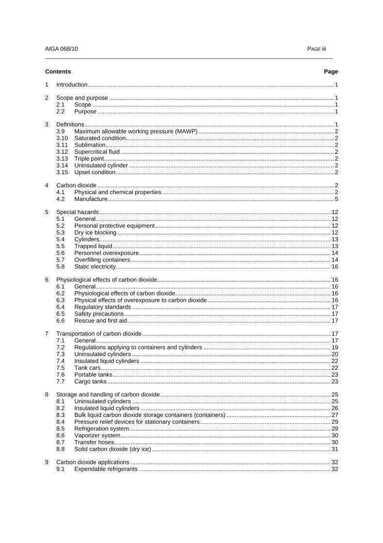
1 Introduction..................................................................................................................................................... 1
2 Scope and purpose ........................................................................................................................................ 1 2.1 Scope .................................................................................................................................................. 1 2.2 Purpose ............................................................................................................................................... 1
3 Definitions....................................................................................................................................................... 1 3.9 Maximum allowable working pressure (MAWP) .................................................................................. 2 3.10 Saturated condition.............................................................................................................................. 2 3.11 Sublimation.......................................................................................................................................... 2 3.12 Supercritical fluid ................................................................................................................................. 2 3.13 Triple point........................................................................................................................................... 2 3.14 Uninsulated cylinder ............................................................................................................................ 2 3.15 Upset condition.................................................................................................................................... 2
4 Carbon dioxide ............................................................................................................................................... 2 4.1 Physical and chemical properties ........................................................................................................ 2 4.2 Manufacture......................................................................................................................................... 5
5 Special hazards............................................................................................................................................ 12 5.1 General.............................................................................................................................................. 12 5.2 Personal protective equipment .......................................................................................................... 12 5.3 Dry ice blocking ................................................................................................................................. 12 5.4 Cylinders............................................................................................................................................ 13 5.5 Trapped liquid.................................................................................................................................... 13 5.6 Personnel overexposure.................................................................................................................... 14 5.7 Overfilling containers ......................................................................................................................... 14 5.8 Static electricity.................................................................................................................................. 16
6 Physiological effects of carbon dioxide......................................................................................................... 16 6.1 General.............................................................................................................................................. 16 6.2 Physiological effects of carbon dioxide.............................................................................................. 16 6.3 Physical effects of overexposure to carbon dioxide .......................................................................... 16 6.4 Regulatory standards ........................................................................................................................ 17 6.5 Safety precautions............................................................................................................................. 17 6.6 Rescue and first aid........................................................................................................................... 17
7 Transportation of carbon dioxide.................................................................................................................. 17 7.1 General.............................................................................................................................................. 17 7.2 Regulations applying to containers and cylinders ............................................................................. 19 7.3 Uninsulated cylinders ........................................................................................................................ 20 7.4 Insulated liquid cylinders ................................................................................................................... 22 7.5 Tank cars........................................................................................................................................... 22 7.6 Portable tanks.................................................................................................................................... 23 7.7 Cargo tanks ....................................................................................................................................... 23
8 Storage and handling of carbon dioxide....................................................................................................... 25 8.1 Uninsulated cylinders ........................................................................................................................ 25 8.2 Insulated liquid cylinders ................................................................................................................... 26 8.3 Bulk liquid carbon dioxide storage containers (containers) ............................................................... 27 8.4 Pressure relief devices for stationary containers............................................................................... 29 8.5 Refrigeration system.......................................................................................................................... 29 8.6 Vaporizer system............................................................................................................................... 30 8.7 Transfer hoses................................................................................................................................... 30 8.8 Solid carbon dioxide (dry ice) ............................................................................................................ 31
9 Carbon dioxide applications ......................................................................................................................... 32 9.1 Expendable refrigerants .................................................................................................................... 32
PAGE iv AIGA 068/10 __________________________________________________________________________________________
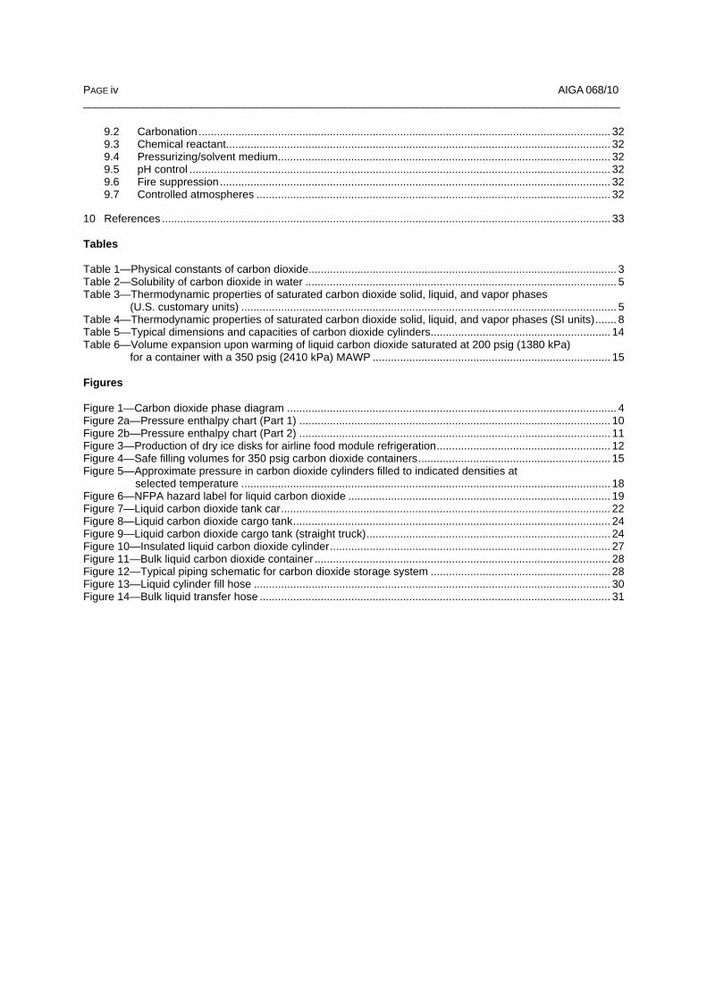
9.2 Carbonation....................................................................................................................................... 32 9.3 Chemical reactant.............................................................................................................................. 32 9.4 Pressurizing/solvent medium............................................................................................................. 32 9.5 pH control .......................................................................................................................................... 32 9.6 Fire suppression................................................................................................................................ 32 9.7 Controlled atmospheres .................................................................................................................... 32
10 References ................................................................................................................................................... 33 Tables Table 1—Physical constants of carbon dioxide..................................................................................................... 3 Table 2—Solubility of carbon dioxide in water ...................................................................................................... 5 Table 3—Thermodynamic properties of saturated carbon dioxide solid, liquid, and vapor phases
(U.S. customary units) ........................................................................................................................... 5 Table 4—Thermodynamic properties of saturated carbon dioxide solid, liquid, and vapor phases (SI units)....... 8 Table 5—Typical dimensions and capacities of carbon dioxide cylinders........................................................... 14 Table 6—Volume expansion upon warming of liquid carbon dioxide saturated at 200 psig (1380 kPa)
for a container with a 350 psig (2410 kPa) MAWP .............................................................................. 15 Figures Figure 1—Carbon dioxide phase diagram ............................................................................................................ 4 Figure 2a—Pressure enthalpy chart (Part 1) ...................................................................................................... 10 Figure 2b—Pressure enthalpy chart (Part 2) ...................................................................................................... 11 Figure 3—Production of dry ice disks for airline food module refrigeration......................................................... 12 Figure 4—Safe filling volumes for 350 psig carbon dioxide containers............................................................... 15 Figure 5—Approximate pressure in carbon dioxide cylinders filled to indicated densities at
selected temperature ......................................................................................................................... 18 Figure 6—NFPA hazard label for liquid carbon dioxide ...................................................................................... 19 Figure 7—Liquid carbon dioxide tank car............................................................................................................ 22 Figure 8—Liquid carbon dioxide cargo tank........................................................................................................ 24 Figure 9—Liquid carbon dioxide cargo tank (straight truck)................................................................................ 24 Figure 10—Insulated liquid carbon dioxide cylinder............................................................................................ 27 Figure 11—Bulk liquid carbon dioxide container ................................................................................................. 28 Figure 12—Typical piping schematic for carbon dioxide storage system ........................................................... 28 Figure 13—Liquid cylinder fill hose ..................................................................................................................... 30 Figure 14—Bulk liquid transfer hose ................................................................................................................... 31

AIGA 068/10 PAGE 1 __________________________________________________________________________________________
1 Introduction
This publication is one of a series compiled by the Compressed Gas Association, Inc. (CGA), to satisfy the de-mand for information relative to the production, storage, transportation, safe handling and use of compressed and liquefied gases, cryogenic liquids, and related products.
As part of the programme of harmonization of industry standards, the Asia Industrial Gases Association (AIGA) has adopted the original CGA standard G-6 as AIGA 068/10. This standard is intended as an international harmonized standard for the use and application by members of CGA, EIGA, JIMGA and AIGA. This edition has the same content as the CGA edition except for editorial changes in formatting, units, spelling and refer-ences to AIGA documents.
2 Scope and purpose
2.1 Scope
The scope includes the physical and chemical properties, physiology, toxicity, special hazards, production, regulations, storage, handling, and applications of carbon dioxide.
2.2 Purpose
The purpose of this publication is to provide information on carbon dioxide. It should be useful to carbon dioxide users, producers, and distributors. Detailed information on the various aspects of carbon dioxide and its trans-portation and use may be found in sources listed in the reference section.
3 Definitions
For the purposes of this publication, the following definitions apply.
3.1 Carbon dioxide A chemical compound consisting of one atom of carbon bonded to two atoms of oxygen expressed by the chemical formula CO2. The shipping name for carbon dioxide in uninsulated cylinders in the United States and Canada is Carbon Dioxide.
3.2 Container An insulated pressure vessel, ASME-coded for the storage of carbon dioxide.
3.3 Critical point The highest pressure and temperature for a pure gas at which the liquid and vapor phases can exist in equilib-rium. For carbon dioxide, this occurs at a temperature of 87.9 °F (31.1 °C) and a pressure of 1070.6 psia (7381.8 kPa, abs).1, 2
3.4 Critical pressure The pressure that must be exerted to produce liquefaction at the critical temperature. For carbon dioxide the critical pressure is 1070.6 psia (7381.8 kPa, abs).
3.5 Critical temperature The temperature above which a pure gas cannot be liquefied regardless of the degree of compression. For carbon dioxide the critical temperature is 87.9 °F (31.1 °C).
1 kPa shall indicate gauge pressure unless otherwise noted as (kPa, abs) for absolute pressure or (kPa, differential) for differential pressure. All kPa values are rounded off per CGA P-11, Metric Practice Guide for the Compressed Gas Industry [1]. 2 References are shown by bracketed numbers and are listed in order of appearance in the reference section.

PAGE 2 AIGA 068/10 _______________________________________________________________________________________
3.6 Cylinder See insulated cylinder (3.8) and uninsulated cylinder (3.14).
3.7 Dry ice The common name for solid carbon dioxide. Its temperature is –109.3 °F (–78.5 °C) at atmospheric pres-sure.
3.8 Insulated cylinder A DOT-approved cylinder with a water capacity not more than 120 U.S. gal (454 L) or 1000 lb (454 kg) and a service pressure rating of at least 40 psia (276 kPa, abs) but not more than 500 psig (3448 kPa), or a TC-approved cylinder with a water capacity not more than 450 L and a service pressure rating from 3.0 bar to 35.0 bar
3.9 Maximum allowable working pressure (MAWP) The maximum gauge pressure permissible at the top of a container in its operating position for a designated temperature [2].
3.10 Saturated condition The condition at which the pressure and temperature of all existing physical states are at equilibrium.
3.11 Sublimation The process of changing from the solid phase directly to the gas phase without passing through the liquid phase.
3.12 Supercritical fluid A substance that is at a pressure and a temperature equal to or greater than its critical point. A substance that has complete mutual solubility of the liquid and the gas.
3.13 Triple point The temperature and pressure at which a material exists simultaneously as a solid, liquid, and gas. For carbon dioxide the triple point is –69.9 °F (–56.6 °C) and 75.1 psia (518 kPa, abs).
3.14 Uninsulated cylinder A cylindrically shaped pressure-containing device with a minimum rated service pressure of 1800 psig (124 bar) and a water capacity no greater than 120 U.S. gal (454 L). The minimum service pressure of 1800 psig (124 bar) is specific to carbon dioxide.
3.15 Upset condition Any condition outside the normal design parameters.
4 Carbon dioxide
4.1 Physical and chemical properties
Carbon dioxide is a colorless, odorless, slightly acid gas that is approximately 50% heavier than air. It is non-flammable and will not support combustion. The physical constants of carbon dioxide are summarized in Table 1. Carbon dioxide can exist as a solid, liquid, gas, or supercritical fluid depending upon conditions of temperature and pressure.
Carbon dioxide at its triple point exists simultaneously as a liquid, gas, and solid at –69.9 °F (–56.6 °C) and 75.1 psia (518 kPa, abs). Any change in pressure or temperature causes carbon dioxide to revert to a two-phase condition (see Figure 1).
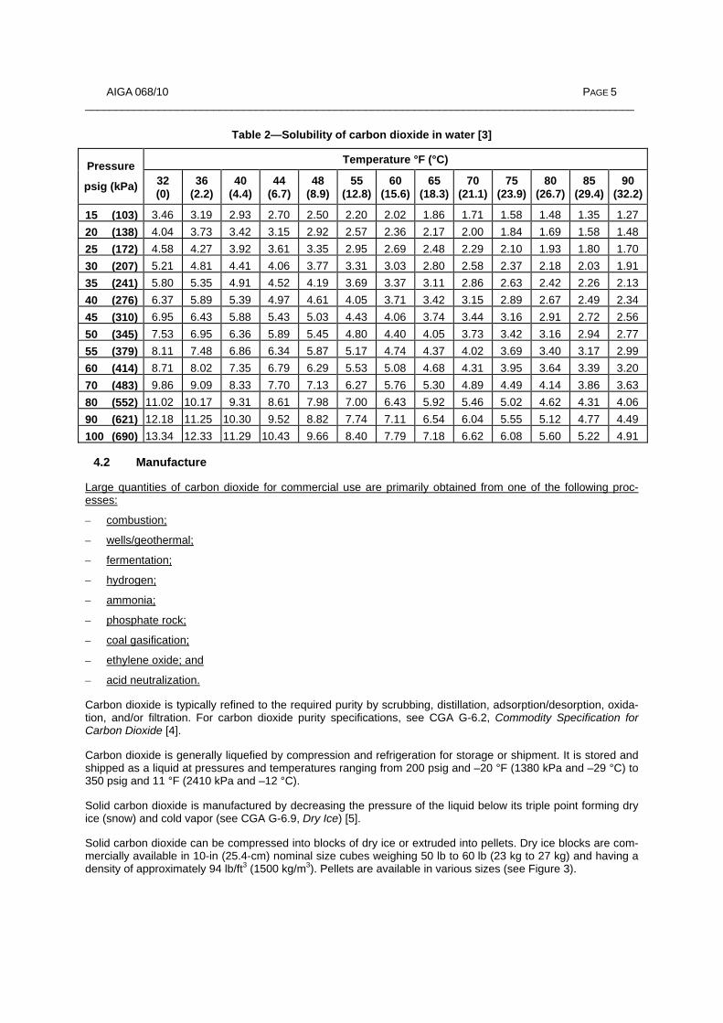
Carbon dioxide at its critical point exists simultaneously as a liquid, gas, and supercritical fluid at 87.9 °F (31.1 °C) and 1070.6 psia (7381.8 kPa). At pressures and temperatures greater than the critical point, carbon dioxide exists only as a supercritical fluid. The solubility of carbon dioxide in water varies with temperature and pressure as shown in Table 2 [3]. Table 2 shows the volume of carbon dioxide measured at 32 °F (0 °C) and 0 psig (0 kPa) that dissolves in one volume of water at the pressure and temperature indicated.

AIGA 068/10 PAGE 3 __________________________________________________________________________________________
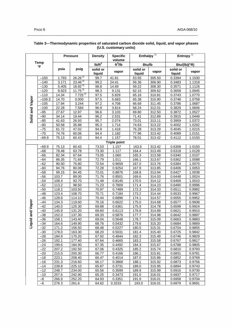
See Tables 3 and 4 and Figure 2 for the thermodynamic and physical properties of carbon dioxide.
Table 1—Physical constants of carbon dioxide (See Tables 3 and 4 for other properties)
Chemical Name: Carbon dioxide
Synonym: Carbon anhydride, carbonic acid gas, carbonic anhydride, dry ice
CAS Registry Number: 124–38–9
U.S. Units SI Units
Chemical formula CO2 CO2
Molecular weight 44.01 44.01
Vapor pressure1) at 2 °F (–16.7 °C) 302 psig 2082 kPa
Specific gravity of the gas at 70 °F (21.1 °C) and 1 atm 1.522 1.522
Solid to gas expansion ratio (specific volume of the gas) at 70 °F (21.1 °C) and 1 atm
8.741 ft3/lb 0.5457 m3/kg
Density of the gas at 70 °F (21.1 °C) and 1 atm 0.1144 lb/ft3 1.833 kg/m3
Density of the liquid saturated at 2 °F (–16.7 °C) 63.3 lb/ft3 (8.46 lb/gal) 1014 kg/m3
Density of solid (dry ice) at 1 atm and –109.3 °F (–78.5 °C)
97.6 lb/ft3 1563 kg/m3
Sublimation temperature at 1 atm –109.3 °F –78.5 °C
Critical temperature 87.9 °F 31.1 °C
Critical pressure 1070.6 psia 7381.8 kPa
Critical density 29.2 lb/ft3 468 kg/m3
Triple point –69.9 °F at 75.1 psia –56.6 °C at 518 kPa, abs
Latent heat of vaporization at 2 °F (–16.7 °C) 119.0 Btu/lb 276.8 kJ/kg
Latent heat of fusion at 1 atm and –69.9 °F (–56.6 °C) 85.6 Btu/lb 199 kJ/kg
Latent heat of sublimation at 1 atm and –109.3 °F (–78.5 °C)
245.5 Btu/lb 571.0 kJ/kg
Specific heat of the gas at 77 °F (25.0 °C) and 1 atm
Cp
0.203 Btu/(lb)(°F) 0.850 kJ/(kg)(°C)
Cv 0.157 Btu/(lb)(°F) 0.657 kJ/(kg)(°C)
Ratio of specific heats (Cp/Cv) at 59 °F (15.0 °C) 1.304 1.304
Solubility in water, vol/vol at 68 °F (20.0 °C) 0.90 0.90
Viscosity of saturated liquid at 2 °F (–16.7 °C) 0.287 lb/(ft)(hr) 0.000119 Pa s 1) All psig values are referenced to 14.696 psia (101.325 kPa, abs).

PAGE 4 AIGA 068/10 _______________________________________________________________________________________
Figure 1—Carbon dioxide phase diagram
AIGA 068/10 PAGE 5 __________________________________________________________________________________________
Table 2—Solubility of carbon dioxide in water [3]
Temperature °F (°C) Pressure
psig (kPa) 32 (0)
36 (2.2)
40 (4.4)
44 (6.7)
48 (8.9)
55 (12.8)
60 (15.6)
65 (18.3)
70 (21.1)
75 (23.9)
80 (26.7)
85 (29.4)
90 (32.2)
15 (103) 3.46 3.19 2.93 2.70 2.50 2.20 2.02 1.86 1.71 1.58 1.48 1.35 1.2720 (138) 4.04 3.73 3.42 3.15 2.92 2.57 2.36 2.17 2.00 1.84 1.69 1.58 1.4825 (172) 4.58 4.27 3.92 3.61 3.35 2.95 2.69 2.48 2.29 2.10 1.93 1.80 1.7030 (207) 5.21 4.81 4.41 4.06 3.77 3.31 3.03 2.80 2.58 2.37 2.18 2.03 1.9135 (241) 5.80 5.35 4.91 4.52 4.19 3.69 3.37 3.11 2.86 2.63 2.42 2.26 2.1340 (276) 6.37 5.89 5.39 4.97 4.61 4.05 3.71 3.42 3.15 2.89 2.67 2.49 2.3445 (310) 6.95 6.43 5.88 5.43 5.03 4.43 4.06 3.74 3.44 3.16 2.91 2.72 2.5650 (345) 7.53 6.95 6.36 5.89 5.45 4.80 4.40 4.05 3.73 3.42 3.16 2.94 2.7755 (379) 8.11 7.48 6.86 6.34 5.87 5.17 4.74 4.37 4.02 3.69 3.40 3.17 2.9960 (414) 8.71 8.02 7.35 6.79 6.29 5.53 5.08 4.68 4.31 3.95 3.64 3.39 3.2070 (483) 9.86 9.09 8.33 7.70 7.13 6.27 5.76 5.30 4.89 4.49 4.14 3.86 3.6380 (552) 11.02 10.17 9.31 8.61 7.98 7.00 6.43 5.92 5.46 5.02 4.62 4.31 4.0690 (621) 12.18 11.25 10.30 9.52 8.82 7.74 7.11 6.54 6.04 5.55 5.12 4.77 4.49100 (690) 13.34 12.33 11.29 10.43 9.66 8.40 7.79 7.18 6.62 6.08 5.60 5.22 4.91
4.2 Manufacture
Large quantities of carbon dioxide for commercial use are primarily obtained from one of the following proc-esses:
– combustion;
– wells/geothermal;
– fermentation;
– hydrogen;
– ammonia;
– phosphate rock;
– coal gasification;
– ethylene oxide; and
– acid neutralization.
Carbon dioxide is typically refined to the required purity by scrubbing, distillation, adsorption/desorption, oxida-tion, and/or filtration. For carbon dioxide purity specifications, see CGA G-6.2, Commodity Specification for Carbon Dioxide [4].
Carbon dioxide is generally liquefied by compression and refrigeration for storage or shipment. It is stored and shipped as a liquid at pressures and temperatures ranging from 200 psig and –20 °F (1380 kPa and –29 °C) to 350 psig and 11 °F (2410 kPa and –12 °C).
Solid carbon dioxide is manufactured by decreasing the pressure of the liquid below its triple point forming dry ice (snow) and cold vapor (see CGA G-6.9, Dry Ice) [5].
Solid carbon dioxide can be compressed into blocks of dry ice or extruded into pellets. Dry ice blocks are com-mercially available in 10-in (25.4-cm) nominal size cubes weighing 50 lb to 60 lb (23 kg to 27 kg) and having a density of approximately 94 lb/ft3 (1500 kg/m3). Pellets are available in various sizes (see Figure 3).
PAGE 6 AIGA 068/10 _______________________________________________________________________________________
Table 3—Thermodynamic properties of saturated carbon dioxide solid, liquid, and vapor phases (U.S. customary units)
Pressure Density Specific volume
Enthalpy 1) Entropy 1)
lb/ft3 ft3/lb Btu/lb Btu/(lb)(°R) Temp °F psia psig solid or
liquid vapor solid orliquid vapor solid or
liquid vapor
–150 1.793 26.26 2) 99.7 41.81 53.55 305.50 0.3394 1.1530 –140 3.171 23.46 2) 99.2 24.41 56.36 306.90 0.3483 1.1318 –130 5.405 18.92 2) 98.8 14.69 59.22 308.30 0.3571 1.1126 –120 8.923 11.75 2) 98.3 9.131 62.15 309.62 0.3658 1.0945 –110 14.34 7.725 2) 97.5 5.829 65.16 310.81 0.3743 1.0770 –109.3 14.70 0.000 97.5 5.683 65.38 310.90 0.3748 1.0758 –105 17.94 3.244 97.2 4.708 66.69 311.45 0.3786 1.0687 –100 22.28 7.584 96.9 3.814 68.24 312.01 0.3829 1.0606 –95 27.67 12.97 96.6 3.103 69.80 312.50 0.3872 1.0527 –90 34.14 19.44 96.2 2.531 71.41 312.89 0.3915 1.0449 –85 41.63 26.93 95.7 2.074 73.01 313.11 0.3959 1.0372 –80 50.58 35.88 95.3 1.714 74.63 313.22 0.4002 1.0292 –75 61.72 47.02 94.9 1.418 76.28 313.29 0.4045 1.0215 –70 74.76 60.06 94.4 1.182 77.96 313.42 0.4089 1.0151 –69.9 75.13 60.43 94.4 1.157 78.01 313.42 0.4112 1.0150
Triple point –69.9 75.13 60.43 73.53 1.157 163.6 313.42 0.6308 1.0150 –68 78.48 63.78 73.30 1.117 164.4 313.49 0.6318 1.0128 –66 82.34 67.64 73.05 1.060 165.3 313.58 0.6340 1.0107 –64 86.35 71.65 72.79 1.011 166.1 313.67 0.6362 1.0088 –62 90.50 75.80 72.54 0.9659 167.0 313.76 0.6384 1.0070 –60 94.76 80.06 72.28 0.9254 167.9 313.85 0.6406 1.0053 –58 99.15 84.45 72.01 0.8876 168.8 313.94 0.6427 1.0038 –56 103.7 89.00 71.76 0.8501 169.6 314.03 0.6448 1.0024 –54 108.4 93.70 71.49 0.8145 170.5 314.12 0.6469 1.0010 –52 113.2 98.50 71.23 0.7809 171.4 314.23 0.6490 0.9996 –50 118.2 103.50 70.97 0.7489 172.3 314.33 0.6511 0.9982 –48 123.4 108.70 70.71 0.7184 173.2 314.44 0.6533 0.9967 –46 128.8 114.10 70.44 0.6896 174.1 314.57 0.6555 0.9952 –44 134.3 119.60 70.16 0.6622 175.0 314.68 0.6577 0.9938 –42 140.0 125.30 69.88 0.6361 175.9 314.78 0.6599 0.9924 –40 145.9 131.20 69.60 0.6113 176.8 314.89 0.6621 0.9910 –38 152.0 137.30 69.33 0.5876 177.7 314.98 0.6642 0.9897 –36 158.1 143.40 69.04 0.5648 178.7 315.09 0.6663 0.9883 –34 164.6 149.90 68.76 0.5432 179.6 315.20 0.6684 0.9869 –32 171.2 156.50 68.48 0.5227 180.5 315.31 0.6704 0.9855 –30 178.0 163.30 68.20 0.5031 181.4 315.40 0.6725 0.9842 –28 184.9 170.20 67.92 0.4844 182.3 315.49 0.6746 0.9829 –26 192.1 177.40 67.64 0.4665 183.2 315.58 0.6767 0.9817 –24 199.6 184.90 67.35 0.4492 184.3 315.67 0.6788 0.9805 –22 207.2 192.50 67.06 0.4325 185.2 315.74 0.6810 0.9793 –20 215.0 200.30 66.77 0.4166 186.1 315.81 0.6831 0.9781 –18 223.1 208.40 66.47 0.4014 187.0 315.86 0.6852 0.9769 –16 231.3 216.60 66.17 0.3868 188.1 315.92 0.6873 0.9756 –14 239.8 225.10 65.87 0.3731 189.0 315.95 0.6894 0.9743 –12 248.7 234.00 65.56 0.3599 189.9 315.99 0.6916 0.9730 –10 257.6 242.90 65.25 0.3473 191.0 316.01 0.6937 0.9717 –8 266.9 252.20 64.93 0.3351 191.9 316.01 0.6958 0.9704 –6 276 3 261.6 64.62 0.3233 193.0 316.01 0.6979 0.9691
Solid
and
Vap
or
Liqu
id a
nd V
apo r

AIGA 068/10 PAGE 7 __________________________________________________________________________________________
Pressure Density Specific volume
Enthalpy 1) Entropy 1)
lb/ft3 ft3/lb Btu/lb Btu/(lb)(°R) Temp °F psia psig solid or
liquid vapor solid orliquid vapor solid or
liquid vapor
–4 285.8 271.1 64.29 0.3119 193.9 315.99 0.7000 0.9678 –2 295.7 281.0 63.96 0.3010 194.9 315.95 0.7022 0.9666 + 0 305.8 291.1 63.63 0.2906 195.8 315.92 0.7043 0.9654 2 316.3 301.6 63.30 0.2805 196.9 315.88 0.7064 0.9642 4 327.0 312.3 62.97 0.2707 198.0 315.83 0.7085 0.9629 6 337.9 323.2 62.64 0.2613 198.9 315.76 0.7106 0.9616 8 349.0 334.3 62.30 0.2523 200.0 315.68 0.7127 0.9603 10 360.5 345.8 61.99 0.2436 200.9 315.59 0.7148 0.9589 12 372.2 357.5 61.69 0.2353 202.0 315.50 0.7169 0.9575 14 384.3 369.6 61.32 0.2273 203.0 315.40 0.7190 0.9561 16 396.5 381.8 61.02 0.2196 204.1 315.27 0.7211 0.9547 18 409.0 394.3 60.67 0.2122 205.2 315.13 0.7232 0.9533 20 421.9 407.2 60.32 0.2050 206.3 314.96 0.7253 0.9520 22 435.1 420.4 59.91 0.1980 207.4 314.80 0.7275 0.9507 24 448.7 434.0 59.57 0.1911 208.4 314.62 0.7297 0.9493 26 462.5 447.8 59.17 0.1845 209.5 314.42 0.7319 0.9479 28 476.6 461.9 58.78 0.1783 210.6 314.19 0.7341 0.9465 30 490.8 476.1 58.40 0.1722 211.7 313.90 0.7363 0.9450 32 505.5 490.8 58.02 0.1663 212.8 313.58 0.7385 0.9434 34 520.5 505.8 57.59 0.1602 214.0 313.20 0.7407 0.9417 36 536.0 521.3 57.12 0.1542 215.1 312.77 0.7429 0.9399 38 551.7 537.0 56.70 0.1482 216.4 312.28 0.7452 0.9380 40 567.7 553.0 56.29 0.1425 217.4 311.76 0.7475 0.9360 42 584.0 569.3 55.89 0.1372 218.7 311.20 0.7598 0.9340 44 600.8 586.1 55.44 0.1321 220.0 310.63 0.7521 0.9321 46 617.8 603.1 54.95 0.1273 221.2 310.05 0.7544 0.9302 48 635.2 620.5 54.43 0.1226 222 5 309.47 0.7568 0.9283 50 652.9 638.2 53.91 0.1181 223.7 308.90 0.7593 0.9264 52 671.2 656.5 53.45 0.1138 225.0 308.32 0.7618 0.9246 54 689.7 675.0 52.95 0.1095 226.4 307.75 0.7643 0.9227 56 708.6 693.9 52.37 0.1054 227.7 307.13 0.7668 0.9207 58 727.9 713.2 51.81 0.1014 229.1 306.49 0.7694 0.9187 60 747.6 732.9 51.17 0.09752 230.6 305.78 0.7720 0.9166 62 767.7 753.0 50.47 0.09372 232.0 305.03 0.7746 0.9145 64 788.3 773.6 49.78 0.08999 233.5 304.22 0.7773 0.9123 66 809.3 794.6 49.08 0.08631 235.1 303.35 0.7801 0.9100 68 830.8 816.1 48.39 0.08261 236.7 302.45 0.7830 0.9077 70 852.7 838.0 47.62 0.07894 238 3 301.52 0.7861 0.9053 72 875.0 860.3 46.80 0.07535 240.3 300.51 0.7894 0.9030 74 897.8 883.1 45.90 0.07173 242.1 299.39 0.7930 0.9006 76 921.1 906.4 44.94 0.06811 244.3 298.10 0.7970 0.8982 78 945.1 930.4 43.90 0.06411 246.4 296.57 0.8013 0.8957 80 969.5 954.8 42.67 0.06013 248.9 294.75 0.8060 0.8924 82 994.5 979.8 41.23 0.05603 251.5 292.46 0.8112 0.8881 84 1020 1005 39.59 0.05171 254.7 289.67 0.8170 0.8821 86 1046 1031 37.03 0.04711 259.0 285.64 0.8249 0.8737 87.9 1071 1056 29.21 0.03423 272.7 272.70 0.8483 0.8483 1) Based on 0 for the perfect crystal at absolute zero temperature, –459.67 °F (–273.15 °C). 2) Inches of mercury below atmospheric pressure.
Liqu
id a
nd V
apor

PAGE 8 AIGA 068/10 _______________________________________________________________________________________
Table 4—Thermodynamic properties of saturated carbon dioxide solid, liquid, and vapor phases (SI units)
Pressure Density
Specific volume
Enthalpy 1)
Entropy
kg/m3
m3/kg x 10–3 kJ/kg kJ/(kg)(K) Temp °C kPa
absolute kPa
gauge solid orliquid vapor solid or
liquid vapor solid or liquid vapor
–102 11.36 –89.97 1597 2837 123.5 710.1 1.415 4.841 –100 13.97 –87.36 1595 2327 125.8 711.3 1.428 4.809 –98 17.15 –84.18 1593 1916 128.2 712.4 1.442 4.777 –96 20.95 –80.38 1591 1583 130.5 713.6 1.455 4.746 –94 25.49 –75.84 1588 1314 132.9 714.8 1.469 4.716 –92 30.89 –70.44 1585 1095 135.3 715.9 1.482 4.687 –90 37.27 –64.06 1582 917.3 137.7 717.1 1.495 4.658 –88 44.76 –56.57 1579 771.9 140.2 718.2 1.508 4.630 –86 53.53 –47.80 1576 651.3 142.6 719.3 1.521 4.603 –84 63.77 –37.56 1573 550.7 145.1 720.4 1.534 4.376 –82 75.72 –25.61 1569 467.1 147.6 721.4 1.548 4.550 –80 89.62 –11.71 1565 397.7 150.1 722.4 1.561 4.523 –78.5 101.3 0.0 1562 354.7 152.1 723.1 1.569 4.504 –78 105.7 4.4 1561 339.8 152.7 723.4 1.574 4.498 –76 124.2 22.9 1558 291.1 155.3 724.4 1.586 4.473 –74 145.6 44.3 1554 249.9 157.9 725.4 1.599 4.449 –72 170.0 68.7 1549 215.1 160.5 726.3 1.612 4.425 –70 198.1 96.8 1545 185.7 163.1 727.1 1.625 4.402 –68 230.2 128.9 1541 160.8 165.8 727.7 1.638 4.378 –66 267.0 165.7 1536 139.5 168.4 728.1 1.651 4.353 –64 308.9 207.6 1532 121.1 171.1 728.4 1.664 4.328 –62 356.7 255.4 1527 105.1 173.9 728.6 1.677 4.304 –60 409.8 308.5 1522 91.23 176.7 728.7 1.690 4.281 –58 467.1 365.8 1517 81.00 179.5 728.8 1.703 4.262 –56.6 518.0 416.7 1513 72.22 181.4 729.0 1.722 4.250
Triple point –56.6 518.0 416.7 1178 72.22 380.5 729.0 2.641 4.250 –56 531.7 430.4 1176 71.10 381.5 729.1 2.643 4.244 –54 578.9 477.6 1168 64.72 385.2 729.5 2.659 4.229 –52 629.5 528.2 1161 59.78 388.9 729.8 2.675 4.215 –50 683.6 582.3 1154 55.41 392.5 730.2 2.691 4.203 –48 741.0 639.7 1146 51.36 396.2 730.6 2.707 4.192 –46 801.9 700.6 1139 47.63 399.9 731.1 2.723 4.181 –44 866.3 865.0 1131 44.20 403.7 731.5 2.739 4.170 –42 934.3 833.0 1123 41.05 407.5 732.0 2.756 4.160 –40 1006 904.7 1115 38.16 411.3 732.4 2.772 4.149 –38 1082 981 1107 35.52 415.1 732.9 2.788 4.139 –36 1162 1061 1099 33.11 419.0 733.3 2.803 4.129 –34 1246 1145 1091 30.90 422.9 733.7 2.819 4.119 –32 1335 1234 1083 28.87 426.8 734.1 2.835 4.109 –30 1429 1328 1074 27.00 430.8 734.4 2.851 4.100 –28 1527 1426 1066 25.27 434.8 734.7 2.867 4.091 –26 1630 1529 1057 23.66 438.8 734.9 2.883 4.081 –24 1739 1638 1048 22.16 442.8 735.0 2.899 4.072 –22 1852 1751 1039 20.76 446.9 735.0 2.915 4.062 –20 1971 1870 1030 19.45 451.0 735.0 2.931 4.053 –18 2095 1994 1021 18.24 455.1 734.9 2.947 4.044 –16 2226 2125 1011 17.13 459.3 734.7 2.963 4.034 –14 2362 2261 1002 16.09 463.6 734.4 2.979 4.024
Solid
and
Vap
or
Liqu
id a
nd V
apo r

AIGA 068/10 PAGE 9 __________________________________________________________________________________________
Pressure Density
Specific volume
Enthalpy 1)
Entropy
kg/m3
m3/kg x 10–3 kJ/kg kJ/(kg)(K) Temp °C kPa
absolute kPa
gauge solid orliquid vapor solid or
liquid vapor solid or liquid vapor
–12 2503 2402 991.9 15.11 467.8 734.1 2.994 4.014 –10 2649 2548 982.0 14.19 472.2 733.6 3.010 4.004 –8 2804 2703 971.8 13.34 476.6 733.0 3.027 3.993 –6 2964 2863 961.5 12.54 481.1 732.2 3.043 3.983 –4 3131 3030 951.5 11.79 485.6 731.4 3.059 3.973 –2 3305 3204 940.7 11.07 490.3 730.5 3.076 3.962 0.0 3485 3384 929.4 10.38 495.0 729.4 3.092 3.950 2.0 3673 3572 917.4 9.703 499.8 727.7 3.109 3.937 4.0 3869 3768 905.0 9.046 504.7 725.4 3.126 3.923 6.0 4071 3970 892.1 8.435 509.8 723.1 3.143 3.908 8.0 4282 4181 878.0 7.878 515.0 720.8 3.161 3.894 10.0 4501 4400 863.6 7.375 520.4 718.5 3.179 3.879 12.0 4730 4629 848.2 6.900 525.9 716.1 3.198 3.864 14.0 4966 4865 831.9 6.446 531.6 713.5 3.217 3.849 16.0 5210 5109 814.3 6.006 537.6 710.5 3.236 3.833 18.0 5464 5363 795.5 5.577 543.8 707.2 3.256 3.817 20.0 5727 5626 775.2 5.157 550.4 703.5 3.278 3.800 22.0 6001 5900 753.6 4.745 557.8 699.4 3.303 3.783 24.0 6285 6184 728.9 4.337 566.0 694.6 3.331 3.765 26.0 6581 6480 696.4 3.914 575.4 688.2 3.364 3.745 28.0 6890 6789 655.7 3.460 586.3 679.1 3.403 3.710 30.0 7211 7110 593.1 2.910 602.5 664.4 3.454 3.658 31.1 7382 7281 467.9 2.137 634.3 634.3 3.552 3.552
1) Based on 0 for the perfect crystal at zero kelvin (–273.15 °C).
Liqu
id a
nd V
apor

PAGE 10 AIGA 068/10 _______________________________________________________________________________________
ENTHALPY—Btu per lb
Figure 2a—Pressure enthalpy chart (Part 1)
1500
1400
1300
1200
1100
1000
900
800
700
600
500
400
300
200
100
-120 -100 -110 -90 -80 -70 -60 -50 -40 -30 -20 -10 0 10 20 30 40
4030 20 10 0
CARBON DIOXIDE
Pressures are in pounds per square inch absolute Temperatures are in degrees Fahrenheit
Based upon the data from Plank & Kuprianoff
Enthalpy values are based upon the ASHRAE Baseline of –40 °F
70 60 50 40 30 20 10
0
75.1 psia
PRESSURE ENTHALPY CHART
50
50

AIGA 068/10 PAGE 11 __________________________________________________________________________________________
ENTHALPY—Btu per lb
Figure 2b—Pressure enthalpy chart (Part 2)
60 70 80 90 100 110 120 130 220210200 190 180 1701601501401500
1400
1300
1200
1100
1000
900
800
700
600
500
400
300
200
10070 60 5040302010 0
220210200 190 180 170160150140120110 100 90 80 70 13060

PAGE 12 AIGA 068/10 ________________________________________________________________________________________
Figure 3—Production of dry ice disks for airline food module refrigeration
5 Special hazards
5.1 General
Personnel handling liquid carbon dioxide should be thoroughly familiar with its associated hazards. There are several conditions in which extreme danger to personnel and equipment may exist. The following describes these conditions and offers procedures and guidelines to prevent dangerous conditions from developing.
5.2 Personal protective equipment
Always wear heavy gloves and eye protection when handling equipment containing vapor, liquid, and solid car-bon dioxide. Contact between exposed skin and cold piping or carbon dioxide vapor can cause frost burns. Dry ice particles formed by depressurizing liquid carbon dioxide are extremely cold and can cause severe damage to unprotected eyes or skin.
5.3 Dry ice blocking
Liquid carbon dioxide in a hose or pipe flows like water. However, when the pressure is reduced below 75.1 psia (518 kPa, abs), the liquid changes into a mixture of vapor and solid carbon dioxide. Solid carbon diox-ide, when formed in a pipe or hose, may create a plug and prevent depressurization that creates a safety haz-ard. The dry ice can be compacted into a plug that can trap gas.
The pressure behind or within a plug can increase as the dry ice sublimes until the plug is forcibly ejected or the hose or pipe ruptures. A dry ice plug can be ejected from any open end of a hose or pipe with enough force to cause serious injury to personnel, from the impact of the dry ice plug or the sudden whip of the hose or pipe as the plug ejects or both.
5.3.1 Liquid line depressurization
To prevent dry ice blockage, the liquid carbon dioxide must be purged from the hose or pipe with vapor greater than 200 psig (1380 kPa) before reducing the pressure below 75.1 psia (518 kPa, abs). This can be done by supplying carbon dioxide vapor to one end of the hose or piping system to maintain the pressure above the triple point while removing the liquid from the other end. This can be accomplished by using a crossover line.

AIGA 068/10 PAGE 13 ________________________________________________________________________________________
5.3.2 Liquid line pressurization to prevent dry ice blockage when liquid is introduced
To prevent dry ice blocking, liquid piping must be pressurized with carbon dioxide gas to more than 200 psig (1380 kPa) before introducing liquid carbon dioxide.
Flexing elastomer hoses containing residual dry ice inside can lead to fracturing of the inner liner, which can lead to catastrophic failure.
5.3.3 Low temperature effects on materials
Depressurization of a liquid carbon dioxide system can result in low temperature liquid carbon dioxide and/or the formation of dry ice placing the container, piping, and hoses in an upset condition below the system design temperatures. For further information, see CGA G-6.7, Safe Handling of Liquid Carbon Dioxide Containers That Have Lost Pressure [6].
Many materials safe to use at normal liquid carbon dioxide temperatures may become brittle and fail if stressed when subjected to dry ice temperatures (–109.3 °F [–78.5 °C]). Materials used in the construction of carbon dioxide transfer systems including hoses must be compatible with carbon dioxide and the temperature and pressure conditions encountered.
Piping systems subject to operating temperatures below ambient will contract. Allowances shall be made in piping and support systems to compensate for these changes in dimensions. Commonly used copper tubing will shrink approximately 1 in (2.5 cm) per 100 ft (30.5 m) for every 100 °F (55.6 °C) reduction in temperature.
For further information on piping systems, see G-6.1, Standard for Insulated Liquid Carbon Dioxide Systems at Consumer Sites [7].
5.4 Cylinders
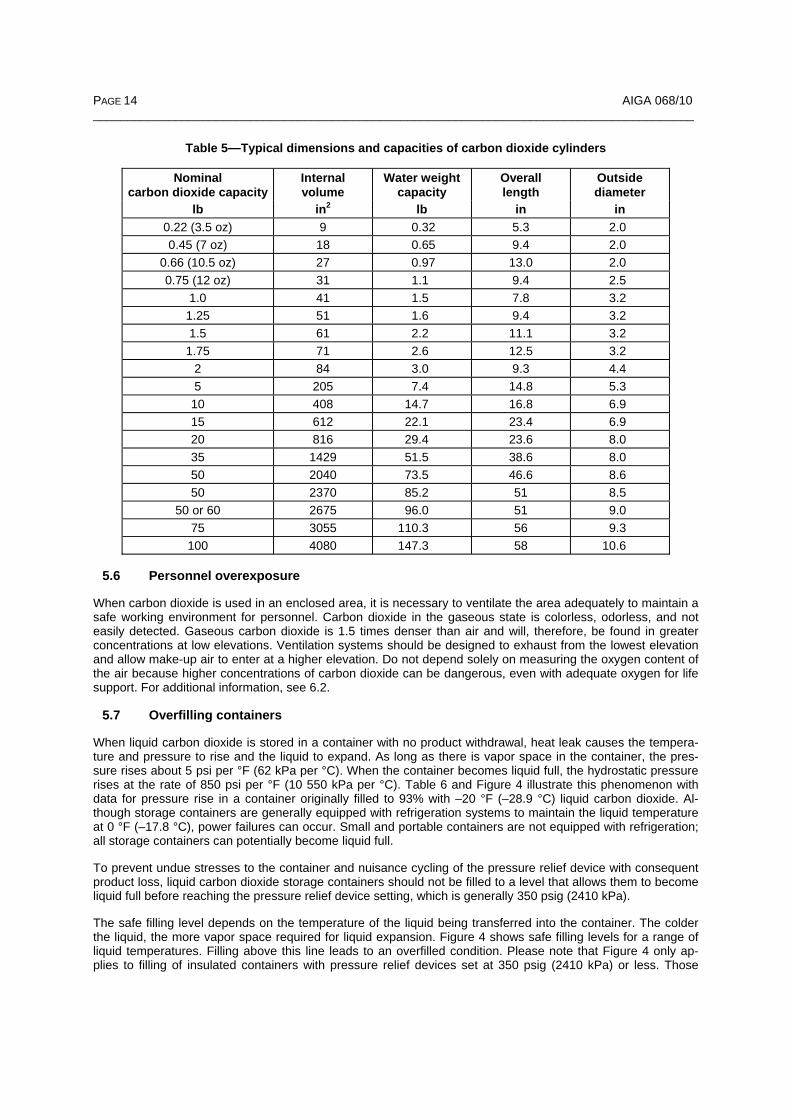
Carbon dioxide cylinders are currently fabricated from steel or aluminum with a minimum rated service pressure of 1800 psig (124 bar). The U.S. Department of Transportation (DOT) and Transport Canada (TC) are the rec-ognized regulatory agencies in the United States and Canada that regulate the manufacture of carbon dioxide cylinders [8, 9]. Typical dimensions and capacities of the most commonly used carbon dioxide cylinders are listed in Table 5.
Aluminum cylinders subjected to heat or fire shall not be used again. Temperatures in excess of 350 °F (177 °C) will irreversibly change the properties of the aluminum and the cylinder must be condemned. If there is any evidence or suspicion of exposure to excessive heat, condemn the cylinder.
5.5 Trapped liquid
When liquid carbon dioxide is forced to occupy a fixed volume such as between two closed valves or within a valve, its pressure will increase as it warms and expands. As long as there is vapor space in the valve or pipe, the pressure rises about 5 psi per °F (62 kPa per °C). When the pipe or valve becomes liquid full, the hydro-static pressure rises at the rate of 850 psi per °F (10 550 kPa per °C). As the temperature continues to in-crease, the pressure of the trapped liquid can exceed what the piping and hoses can withstand. This will cause rupture of the hose or piping with possible injury and property damage.
To prevent trapped liquid from becoming a hazard, all liquid carbon dioxide piping and transfer lines shall be equipped with pressure relief devices located in all parts of the system in which liquid can be trapped such as between valves, check valves, and pumps. These pressure relief devices shall be set to discharge within the design pressure of the part of the system they protect and should discharge into a well-ventilated area (see CGA G-6.5, Standard for Small, Stationary, Insulated Carbon Dioxide Supply Systems) [10].
To prevent trapped liquid from becoming a hazard in ball- and gate-type valves, they shall be adequately de-signed to prevent liquid carbon dioxide from being trapped within the valve.
PAGE 14 AIGA 068/10 ________________________________________________________________________________________
Table 5—Typical dimensions and capacities of carbon dioxide cylinders
Nominal carbon dioxide capacity
Internal volume
Water weight capacity
Overall length
Outside diameter
lb in2 lb in in 0.22 (3.5 oz) 9 0.32 5.3 2.0 0.45 (7 oz) 18 0.65 9.4 2.0
0.66 (10.5 oz) 27 0.97 13.0 2.0 0.75 (12 oz) 31 1.1 9.4 2.5
1.0 41 1.5 7.8 3.2 1.25 51 1.6 9.4 3.2 1.5 61 2.2 11.1 3.2
1.75 71 2.6 12.5 3.2 2 84 3.0 9.3 4.4 5 205 7.4 14.8 5.3
10 408 14.7 16.8 6.9 15 612 22.1 23.4 6.9 20 816 29.4 23.6 8.0 35 1429 51.5 38.6 8.0 50 2040 73.5 46.6 8.6 50 2370 85.2 51 8.5
50 or 60 2675 96.0 51 9.0 75 3055 110.3 56 9.3 100 4080 147.3 58 10.6
5.6 Personnel overexposure
When carbon dioxide is used in an enclosed area, it is necessary to ventilate the area adequately to maintain a safe working environment for personnel. Carbon dioxide in the gaseous state is colorless, odorless, and not easily detected. Gaseous carbon dioxide is 1.5 times denser than air and will, therefore, be found in greater concentrations at low elevations. Ventilation systems should be designed to exhaust from the lowest elevation and allow make-up air to enter at a higher elevation. Do not depend solely on measuring the oxygen content of the air because higher concentrations of carbon dioxide can be dangerous, even with adequate oxygen for life support. For additional information, see 6.2.
5.7 Overfilling containers
When liquid carbon dioxide is stored in a container with no product withdrawal, heat leak causes the tempera-ture and pressure to rise and the liquid to expand. As long as there is vapor space in the container, the pres-sure rises about 5 psi per °F (62 kPa per °C). When the container becomes liquid full, the hydrostatic pressure rises at the rate of 850 psi per °F (10 550 kPa per °C). Table 6 and Figure 4 illustrate this phenomenon with data for pressure rise in a container originally filled to 93% with –20 °F (–28.9 °C) liquid carbon dioxide. Al-though storage containers are generally equipped with refrigeration systems to maintain the liquid temperature at 0 °F (–17.8 °C), power failures can occur. Small and portable containers are not equipped with refrigeration; all storage containers can potentially become liquid full.
To prevent undue stresses to the container and nuisance cycling of the pressure relief device with consequent product loss, liquid carbon dioxide storage containers should not be filled to a level that allows them to become liquid full before reaching the pressure relief device setting, which is generally 350 psig (2410 kPa).
The safe filling level depends on the temperature of the liquid being transferred into the container. The colder the liquid, the more vapor space required for liquid expansion. Figure 4 shows safe filling levels for a range of liquid temperatures. Filling above this line leads to an overfilled condition. Please note that Figure 4 only ap-plies to filling of insulated containers with pressure relief devices set at 350 psig (2410 kPa) or less. Those

AIGA 068/10 PAGE 15 ________________________________________________________________________________________
quantities would be a significant overfill of uninsulated high pressure cylinders and also would exceed the maximum filling density allowed for DOT-4L/TC-4LM containers with pressure relief devices set above 350 psig (2410 kPa). DOT tables for filling density go as high as a maximum 625 psig (4310 kPa) pressure relief device setting with an 86% maximum filling density (see 173.304a(e)(2)[8]. For TC, the table in CSA B340, Selection and Use of Cylinders, Spheres, Tubes, and Other Containers for the Transportation of Dangerous Goods, Class 2, goes up to a 4300 kPa pressure control valve setting at 86% maximum filling density [11].
Table 6—Volume expansion upon warming of liquid carbon dioxide saturated at 200 psig (1380 kPa) for a container with a 350 psig (2410 kPa) MAWP
Pressure Temperature Volume occupied by liquid carbon dioxide 1)
psig kPa °F °C % 200 1380 –20 –28.9 92.6 210 1450 –18 –27.8 93.1 220 1520 –15 –26.1 93.5 230 1590 –13 –25.0 94.1 240 1650 –11 –23.9 94.6 250 1720 –8 –22.2 95.1 260 1790 –6 –21.1 95.6 270 1860 –4 –20.0 96.1 280 1930 –2 –18.9 96.6 290 2000 0 –17.8 97.1 300 2070 2 –16.7 97.6 310 2140 4 –15.6 98.1 320 2210 5 –15.0 98.6 330 2280 7 –13.9 99.0 340 2340 9 –12.8 99.5 350 2410 11 –11.7 100.0
1) The percent liquid full is the percent of total vessel volume and should not be confused with the liquid level gauge reading.
100%
90%
300
0
200100
600
400500
700800900
1000110012001300
-20 -18 -16 -12-14 -6-10 -8 -4 20 864 1210-2
Perc
ent l
iqui
d fil
l
Car
bon
diox
ide
cont
aine
r pre
ssur
e (p
sig)
Unsafe region
Safe region(Liquid has space to expand)
93%
Pressure relief devicepressure setting
Liquid carbon dioxide filling temperature (°F)
Figure 4—Safe filling volumes for 350 psig carbon dioxide containers
PAGE 16 AIGA 068/10 ________________________________________________________________________________________
5.8 Static electricity
The manufacturing of solid dry ice produces static electricity charges (> 100 000 volts). This may lead to a dis-charge of the static electricity to any grounded object or person.
Use of carbon dioxide snow or solid dry ice in combustible environments should be carefully evaluated. Liquid carbon dioxide should not be used for inerting combustible atmospheres because of the extremely high static charges produced during the formation of dry ice. Gaseous carbon dioxide can be used for inerting combustible atmospheres without the risk of generating static charges. See CGA SB-33, Static Electricity Hazards of Liquid or Solid Carbon Dioxide for additional information [12].
6 Physiological effects of carbon dioxide
6.1 General
The physiological effects of carbon dioxide are unique because it is a product of normal metabolism, a re-quirement of the body’s normal internal chemical environment, and an active messenger substance in the link-ing of respiration, circulation, and vascular response to the demands of metabolism both at rest and in exer-cise.
The respiratory control system maintains carbon dioxide pressure at a relatively high level of about 50 mm Hg pressure in the arterial blood and tissue fluids. This maintains the acidity of the tissue and cellular fluids at the proper level for essential metabolic reactions and membrane functions. Changes in the normal carbon dioxide tissue pressure can be damaging. If tissue pressure becomes excessively low, which can occur from hyperven-tilation, failure of critical neuromuscular function or loss of consciousness can occur.
Inhaled carbon dioxide produces the same physiological effects as metabolically produced carbon dioxide. As the carbon dioxide tissue pressure rises from inhaling carbon dioxide, the body responds by using respiratory and adaptive processes to adjust to the change. These adaptive processes are limited and cannot cope with severe exposures, which cause pH change to the body fluids. Toxic effects of carbon dioxide, namely severe and disruptive acidosis, occur when high concentrations of carbon dioxide are inhaled.
The blood and cellular fluids are actually solutions of sodium bicarbonate containing numerous other sub-stances. Severe exposure to carbon dioxide forms carbonic acid in the blood for which the sodium bicarbonate is not very effective as a buffer. The decrease in pH has a rapid toxic effect because the neural control systems are excessively driven. It is important to note that these effects are independent of the amount of oxygen in the atmosphere being breathed.
The effects produced by low and moderate concentrations of carbon dioxide are physiological and reversible, but the effects of high concentrations are toxic and damaging [13].
6.2 Physiological effects of carbon dioxide
The response to carbon dioxide inhalation depends on degree and duration of exposure, and it varies greatly even in healthy, normal individuals. The medical term for the physiological effects of excess carbon dioxide in the blood is hypercapnia. Carbon dioxide can be toxic even when normal oxygen levels are present. Low con-centrations of inspired carbon dioxide can be tolerated for a considerable period of time without noticeable ef-fect, or may merely cause an unnatural feeling of shortness of breath. Sustained exposure to 5% carbon diox-ide produces stressful rapid breathing. When the level of inspired carbon dioxide exceeds 7%, the rapid breath-ing becomes labored (dyspnea) and restlessness, faintness, severe headache, and dulling of consciousness occur. At 15%, unconsciousness accompanied by rigidity and tremors occurs in less than 1 minute, and in the 20% to 30% range it produces unconsciousness and convulsions in less than 30 seconds. The reason these effects occur quickly is that carbon dioxide diffuses in the tissue fluids at a rate approximately 20 times more rapidly than oxygen. High concentrations of carbon dioxide can asphyxiate quickly without warning and with no possibility of self-rescue regardless of the oxygen concentration.
6.3 Physical effects of overexposure to carbon dioxide
Skin, mouth, or eye contact with solid carbon dioxide that has a temperature of –109.3 °F (–78.5 °C) can cause severe frostbite, skin lesions, corneal burn, or more serious injury from deep-freezing of the tissues. Liquid dis-
AIGA 068/10 PAGE 17 ________________________________________________________________________________________
CAUTION—CARBON DIOXIDE GAS
Ventilate the area before entering. A high
carbon dioxide gas concentration can occur
in this area and can cause asphyxiation.
charging from a container produces high velocity carbon dioxide snow particles that are abrasive in addition to being cold and will cause similar injuries.
6.4 Regulatory standards
Carbon dioxide is present in the atmosphere at about 350 ppm (0.035%) by volume. The Occupational Safety and Health Administration (OSHA) standard, found in Title 29 of the U.S. Code of Federal Regulations (29 CFR) 1910.1000, specifies that employee exposure to carbon dioxide in any 8-hour shift of a 40-hour work-week shall not exceed the 8-hour time-weighted average (TWA-PEL) of 5000 ppm (0.5%) (9000 mg/m3) [14]. According to the American Conference of Governmental Industrial Hygienists (ACGIH), the short-term expo-sure limit (STEL/Ceiling) for 15 minutes or less is 30 000 ppm (3%) (54 000 mg/m3) [15]. In Canada, similar limits are mandated by provincial legislation.
6.5 Safety precautions
Appropriate warning signs should be placed at the entrance to confined areas where high concentrations of carbon dioxide gas can accumulate. A typical warning is shown below:
Carbon dioxide monitoring should be carried out before entering any confined space or low area in which car-bon dioxide gas may have accumulated. The carbon dioxide shall be removed by ventilation to a concentration below 3% or a supplied-air respirator shall be donned before entering the confined space or low area (see CGA SB-15, Avoiding Hazards in Confined Work Spaces During Maintenance, Construction and Similar Activi-ties) [16].
6.6 Rescue and first aid
Do not attempt to remove anyone exposed to high concentrations of carbon dioxide without using proper res-cue equipment or you may also become a casualty. Rescuers account for over 60% of confined space fatali-ties. If the exposed person is unconscious, obtain assistance and use established emergency procedures.
If a person has inhaled large amounts of carbon dioxide and is exhibiting adverse effects, move the exposed individual to fresh air at once. If breathing has stopped, perform artificial respiration. Only qualified personnel may give oxygen to the victim. Keep the affected person warm and at rest. Get medical attention as soon as possible. Fresh air and assisted breathing is appropriate for all cases of overexposure to gaseous carbon diox-ide. With prompt response to a carbon dioxide emergency, recovery is usually complete and uneventful.
If dry ice or compressed carbon dioxide gas comes in contact with the skin or mouth, stop the exposure imme-diately. If frostbite has occurred, obtain medical attention. Do not rub the area. Immerse in warm water, 100 °F to 105 °F (37.8 °C to 40.6 °C).
7 Transportation of carbon dioxide 7.1 General
Cylinders and containers used for the transportation of carbon dioxide are either insulated or uninsulated. Insu-lated liquid containers commonly have a working pressure between 200 psig and 500 psig (1380 kPa and 3450 kPa). They may be refrigerated to compensate for heat gained by the contents during transport. These containers include insulated liquid cylinders, tank cars, portable tanks, and cargo tanks.
Uninsulated cylinders have a design pressure that will safely contain carbon dioxide at normal ambient tem-peratures. The pressure in these cylinders varies with ambient temperature (see Figure 5).

PAGE 18 AIGA 068/10 ________________________________________________________________________________________
12048.9
1000(6900)
500(3450)
Pres
sure
in p
sia
(kPa
, abs
)
30-1.1
404.4
5010.0
6015.6
10037.8
Temperature
8026.7
9032.2
11043.3
Filling density
13054.4
14060
15065.6
7021.1
68%
90%95% 85% 80%
75%
Typical carbon dioxide rupture disc setting
1500(10 340)
2000(13 790)
2500(17 240)
3000(20 680)
3500(24 130)
4000(27 580)
5000(34 480)
4500(31 030)
F°C°
3)
1)
2)
SAFE TO FILL TO SOLID LINE
UNSAFE - OVERFILLED
NOTE—This chart is based upon a cylinder filled to its correct maximum liquid carbon dioxide capacity of 68% of the total volume (water weight capacity). An overfilled cylinder obviously experiences enormous internal pressures from expansion of the liquid car-bon dioxide as it warms to higher temperatures after filling. 1) Dashed lines indicate temperature-pressure relationship when the cylinder is overfilled. 2) A correctly installed carbon dioxide cylinder rupture disk functions at 2800 psig to 3000 psig (19 310 kPa to 20 680 kPa)
depending on design. 3) Maximum permitted filling capacity is 68%.
Figure 5—Approximate pressure in carbon dioxide cylinders filled to indicated densities at selected temperature
The product shipping names and product identification numbers for the three forms of carbon dioxide shipped are carbon dioxide, UN 1013; carbon dioxide, refrigerated liquid, UN 2187; and carbon dioxide, solid or dry ice, UN 1845.
The DOT and TC hazard classification for carbon dioxide and carbon dioxide refrigerated liquid is 2.2 (non-flammable gas). Under DOT, carbon dioxide solid is Class 9 (miscellaneous hazardous materials) when trans-ported by air or water and unclassified when transported by rail or highway. In Canada, it is Class 9 (miscella-neous dangerous goods) regardless of mode of transportation.
CGA’s recommended hazard ratings for carbon dioxide gas and liquid are as follows in accordance with the National Fire Protection Association (NFPA) rating system and the National Paint and Coatings Association’s (NPCA) Hazardous Material Identification System, Third Edition (HMIS® III) as referenced in CGA P-19 CGA Recommended Hazard Ratings for Compressed Gases and CGA P-24 Guide to the Preparation of Material Safety Data Sheets [17, 18, 19, 20]:
NFPA 1) HMIS® III 1) Gas Gas Health 1 Health 1 Flammability 0 Flammability 0 Instability 0 Physical Hazard 3

AIGA 068/10 PAGE 19 ________________________________________________________________________________________
Special SA 2) Liquid Liquid Health 3 Health 3 Flammability 0 Flammability 0 Instability 0 Physical Hazard 2 Special SA 2) Solid Solid Health 3 Health 3 Flammability 0 Flammability 0 Instability 0 Physical Hazard 0 Special SA 2) 1) CGA's recommended rating of carbon dioxide using NFPA's rating system and HMIS® III. 2) CGA recommends SA to designate a simple asphyxiant.
For an example of an NFPA hazard label, see Figure 6.
Copyright © 2002, 13th Edition, National Fire Protection Association, Quincy, MA 02269. This warning system is intended to be interpreted and applied only by properly trained individuals to identify fire, health, and stability hazards of chemicals. The user is referred to the recommended classifications of certain chemicals in the NFPA Fire Protection Guide to Hazardous Materials, which should be used as a guideline only [21]. Whether the chemicals are classified by NFPA or not, anyone us-ing the NFPA 704 system to classify chemicals does so at their own risk [17].
Figure 6—NFPA hazard label for liquid carbon dioxide
7.2 Regulations applying to containers and cylinders
In the United States, the transportation of carbon dioxide in interstate commerce by rail, highway, air, and water is governed by federal authority under regulations promulgated by DOT [8]. In Canada, TC regulates all modes of transport through the Transportation of Dangerous Goods Act and Regulations [9]. The Canadian Regula-tions adopt these standards: – For rail transport
– Canadian General Standards Board CGSB 43.147–2005, Construction, Modification, Qualification, Main-tenance, and Selection and Use of Means of Containment for the Handling, Offering for Transport, or Transporting of Dangerous Goods by Rail [22];
– For cylinder shipments
– CSA B339, Cylinders, Spheres, and Tubes for the Transportation of Dangerous Goods [23]
– CSA B340 [11]; and
– For bulk shipments by road
– CSA B620, Highway Tanks and Portable Tanks for the Transportation of Dangerous Goods [24]
30
0SA
Red
White
Blue
Yellow
PAGE 20 AIGA 068/10 ________________________________________________________________________________________
– CSA B622, Selection and Use of Highway Tanks, Multi-Unit Tank Car Tanks, and Portable Tanks for the Transportation of Dangerous Goods, Class 2 [25].
The specifications of these regulatory authorities require, among other things, that the materials used for car-bon dioxide containers and cylinders meet certain chemical and physical requirements, pass specified hydro-static pressure tests, and be protected by adequate pressure relief devices.
7.3 Uninsulated cylinders
7.3.1 General
Uninsulated steel cylinders shall comply with DOT specifications 3, 3A-1800, 3AX-1800, 3AA-1800, 3AAX-1800, 3E1800, 3T1800, 3HT2000, or 39. Aluminum cylinders shall comply with DOT-3AL1800.
In Canada, uninsulated steel cylinders shall comply with TC specifications TC-3AM138, CTC-3A1800, TC-3AXM138, CTC-3AX1800, TC-3AAM138, CTC-3AA1800, TC-3AAXM138, CTC-3AAX1800, TC-3EM124, CTC-3E1800, ICC-3, TC-3TM138, TC-39M, CTC-39, TC-3HTM138, CTC-3HT2000, or TC-3ASM138. Aluminum cylinders shall comply with specifications TC-3ALM124 or CTC-3AL1800. Since 1993, Canadian cylinders have been made to metric units as indicated by the letter M in the specification with the service pressure expressed in bar. One bar equals 100 kPa, or approximately 14.5 psi.
7.3.2 Cylinder valves
Carbon dioxide cylinder valve connection standards have been adopted by CGA and recognized as United States and Canadian standards [26]. Carbon dioxide cylinders use a CGA 320 outlet connection. Small medical carbon dioxide cylinders equipped with a yoke-type valve use a CGA 940 outlet connection.
7.3.3 Cylinder pressure relief devices
Carbon dioxide cylinders, with certain exceptions, shall be equipped with pressure relief devices designed to release excessive pressure that can occur from overfilling, exposure to fire, or high temperatures. The mini-mum permissible service pressure rating for uninsulated cylinders in carbon dioxide service is 1800 psig (12 410 kPa). They shall have a rupture disk designed to rupture at no higher than the minimum required test pressure of the cylinder (e.g. 5/3 of the service pressure for DOT cylinders). Details of pressure relief device requirements are in CGA S-1.1, Pressure Relief Device Standards–Part 1–Cylinders for Compressed Gases [27].
7.3.4 Filling limits
Uninsulated carbon dioxide cylinders shall be filled by weight. Care shall be exercised to avoid overfilling, which can contribute to catastrophic failure. DOT limits the weight of carbon dioxide that may be charged into a cylin-der to 68% of the weight of water the cylinder will hold at 60 °F, and CSA B340 specifies a maximum permitted filling density of 68% at 15 °C [8, 11]. If a cylinder is filled over 68%, a rise in temperature could cause the cyl-inder to become liquid full. The pressure in a cylinder filled with carbon dioxide to various percentages of its water capacity is given in Table 2. For detailed information on filling carbon dioxide cylinders, see CGA G-6.3, Carbon Dioxide Cylinder Filling and Handling Procedures [28].
7.3.5 Retesting
Carbon dioxide cylinders (except specification 3HT, 3E, and 39) are required by DOT and TC regulations to be requalified for continued service every 5 years by an authorized retester. Specification 3HT cylinders shall be retested every 3 years. Specification 3E cylinders do not require retesting because they are smaller than 2 in (5 cm) in diameter and 24 in (61 cm) in length. Specification 39 cylinders may not be refilled.
This requalification includes a thorough external and internal visual inspection as well as an internal hydrostatic pressure test (see CGA C-6, Standards for Visual Inspection of Steel Compressed Gas Cylinders; CGA C-6.1, Standards for Visual Inspection of High Pressure Aluminum Compressed Gas Cylinders; CGA C-8, Standard for Requalification of DOT-3HT, CTC-3HT, and TC-3HTM Seamless Steel Cylinders; and CGA C-1, Methods for Hydrostatic Testing of Compressed Gas Cylinders) [29, 30, 31, 32]. For DOT cylinders and older Canadian (CTC, BTC, or CRC) cylinders, the hydrostatic test shall be performed at 5/3 of the stamped service pressure.

AIGA 068/10 PAGE 21 ________________________________________________________________________________________
For metric TC cylinders, the hydrostatic test shall be performed at 1.5 times the marked service pressure. The internal visual inspection shall be carefully performed to detect harmful corrosion because wet carbon dioxide can rapidly corrode a steel cylinder.
Cylinders that have evidence of physical damage (dents, pitting, cracks, arc burns, fire/heat damage, damaged threads, bulges, or any other signs of physical damage) or fail the hydrostatic test shall be removed from ser-vice.
Each requalified cylinder shall be plainly and permanently stamped with the month and year of the test with the retester’s identification number (RIN) between the month and year of the retest date. In the United States, the cylinder owner shall keep a record of the inspection and retest data on all cylinders until the next requalification. In Canada, the cylinder owner shall keep a copy of the requalification report for 10 years.
7.3.6 Marking and labeling
The following marks are required by DOT and TC to be plainly stamped on the shoulder, top head, or neck of all carbon dioxide cylinders:
– DOT or TC specification number followed by the service pressure, for example, DOT-3A1800 or TC-3AM138;
– Serial number and identifying symbol of the cylinder manufacturer. The symbol shall be registered with DOT or TC, or both; and
– Independent inspector’s (third party) official mark and the manufacturing test date. The word SPUN and/or PLUG shall be added when an end closure is made by the spinning process or affected by plugging (see 49 CFR, Part 178, Subpart C, Specifications for cylinders, or CSA B339) [8, 23].
The required markings on cylinders shall not be changed except as prescribed in DOT or TC regulations. The serial number and identifying symbol of the maker shall never be obliterated or changed and shall be kept in a legible condition.
In addition to the required marking listed previously, carbon dioxide cylinders shall be labeled with the following:
– Product shipping name—Carbon Dioxide;
– Product identification number—UN 1013. These markings shall be by means of stenciling, printing, or la-beling; shall not be readily removable; and shall be in accordance with 49 CFR or Canadian regulations [8, 9];
– A 100-mm (3.9-in) green diamond-shaped nonflammable gas label with a cylinder symbol in the upper cor-ner and the hazard class number, 2, in the bottom corner shall be used on every cylinder. In the United States, the use of NONFLAMMABLE GAS on the label is optional. In Canada, its use is not authorized; and
– Alternately, DOT regulations (see 49 CFR 172.400a) allow the use of 30 mm (1.25-in) square-on-point la-bels as long as the cylinder(s) are not overpacked and are durably and legibly marked in accordance with CGA C-7, Guide to the Preparation of Precautionary Labeling and Marking of Compressed Gas Cylinders, Appendix A [8, 33].
– In Canada, the general requirement is for each side of a label to be at least 100 mm in length with a line running 5 mm inside the edge. However, if that size label, together with the shipping name, technical name, and UN number, cannot be displayed because of the irregular shape or size of the small means of con-tainment, each side of the label may be reduced in length by the same amount to the point where the label, together with the shipping name, technical name, and UN number, will fit that small means of containment, but must not be reduced to less than 30 mm. See subsection 4.10(4) of the Transportation of Dangerous Goods Regulations [9].
For additional details on United States and Canadian marking and labeling, see CGA G-6.3 and CGA C-7 [28, 33].
Cylinders equipped with a dip or siphon tube, allowing withdrawal of liquid when the cylinder is upright, shall be clearly identified on the exterior of the cylinder by the words siphon, dip tube, or other descriptive phrase. This
PAGE 22 AIGA 068/10 ________________________________________________________________________________________
does not apply to fire extinguishing cylinders. A gas pressure regulator shall never be attached to a cylinder with a siphon tube.
7.4 Insulated liquid cylinders
DOT and TC authorize the shipment of liquid carbon dioxide in vacuum-insulated cylinders manufactured to the 4L specification.
7.5 Tank cars
7.5.1 General
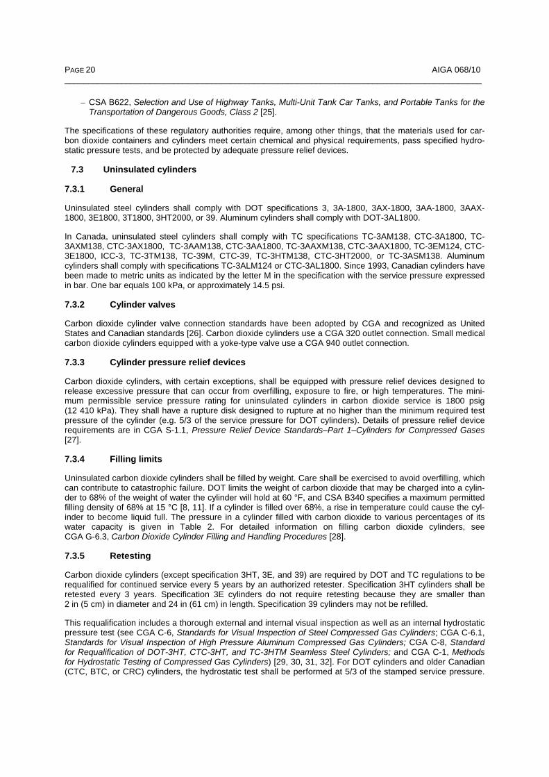
DOT regulations governing the shipment of liquid carbon dioxide are found in 49 CFR 173.314 and 49 CFR 173.31[8]. TC regulations are found in CGSB-43.147-2005 [21]. Both authorize shipments in DOT or TC specification 105A500W, 105S500W, and 105J500W tank cars (see Figure 7) [8].
Figure 7—Liquid carbon dioxide tank car
7.5.2 Pressure relief devices
The pressure relief devices for DOT 105A500 and DOT/TC 105A500W tank cars consist of a primary pressure relief device set to open at 375 psig (2590 kPa) or lower, a rupture disk designed to burst at a pressure less than the tank test pressure [500 psig (3450 kPa)], and two pressure regulating devices set to open at 350 psig (2410 kPa). These devices shall be approved by the Association of American Railroad’s Committee on Tank Cars [see 49 CFR 173.314(b)(4) and 173.314(c)] [8]. Personnel such as railroad employees should be made aware that one or both of the pressure regulating devices routinely open during transportation. The carbon di-oxide escaping during such a valve opening may create a sound that an untrained person may believe to be a hazardous leak. This is normal operation and such railroad tank cars may be safely moved. Railroad tank cars in liquid carbon dioxide service should display a stencil that reads REGULATING VALVES VENTING NORMAL.
7.5.3 Filling limits
DOT and Canadian regulations require that railroad tank cars be filled so the liquid portion of the gas at 0 °F (–17.8 °C) does not completely fill the tank (see 49 CFR 173.314, Note 5 and CGSB 43.147-2005) [8, 22]. A relationship of volume to temperature in containers is shown in Figure 5.
7.5.4 Retesting and requalification
Tank cars in liquid carbon dioxide service shall be requalified at least once every 10 years (see 49 CFR 180.509(c) and CGSB 43.147–2005) [8, 22]. Pressure relief devices shall be requalified every 5 years (See 49 CFR 180.509(c)(3)(ii)) and 180.509(h) [8]. The dates of requalification of the tank and pressure relief devices shall be stenciled on the tank car.

AIGA 068/10 PAGE 23 ________________________________________________________________________________________
7.6 Portable tanks
7.6.1 General
DOT authorizes the shipment of liquefied carbon dioxide in portable tanks complying with DOT specifica-tion 51 as well as certain other portable tanks as outlined in 49 CFR 173.32(b). For further details, refer to 49 CFR 173.315 [8]. In Canada, TC 51 portable tanks may be used in accordance with CSA B622 or CGSB 43.147–2005 [25, 22].
7.6.2 Pressure relief device
Each portable tank shall be provided with one or more pressure relief devices of the pilot-operated or spring-loaded type. A portable tank may also be provided with a pressure-controlling device that regulates the internal pressure by venting when the pressure reaches a preset point below the start-to-discharge pressure of the pressure relief device [see 49 CFR 173.315(i)(9) and (11)] [8]. Details of pressure relief device requirements are contained in CGA S-1.2, Pressure Relief Device Standards–Part 2–Portable Containers for Compressed Gases [34].
7.6.3 Filling limits
DOT regulations prohibit filling portable tanks in excess of 95% of their volumetric capacity, which is typically determined during the filling operation by using fixed-length internal dip tubes or by weighing [8]. Depending upon the temperature of the carbon dioxide being loaded, it may be necessary to fill to a lower percentage level to prevent them from becoming liquid full before reaching the start-to-discharge pressure of the pressure relief device (see 49 CFR 173.315) [8]. A relationship of volume to temperature in containers is shown in Figure 5.
7.6.4 Retesting
Portable tanks in carbon dioxide service shall be subjected to a hydrostatic pressure test at least once every 5 years. The retest pressure shall be a minimum of 1.5 times the design pressure. For a specification TC/DOT-51 portable tank, the minimum design pressure is 200 psig (1380 kPa). A portable tank that has been out of service for a period of 1 year or more shall be retested before being returned to service (see 49 CFR 180.605(b) or CSA B620) [8, 23]. The date of the most recent retest shall be marked on the portable tank on or near the metal certification plate [see 49 CFR 180.605(k) or CSA B620] [8, 24].
7.7 Cargo tanks
7.7.1 General
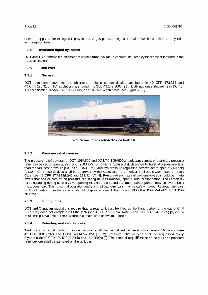
DOT authorizes the shipment of liquid carbon dioxide in cargo tanks complying with specifications MC-330 and TC/MC-331 [8]. In Canada, TC authorizes the shipment of liquid carbon dioxide in TC 331 or TC 338 highway tanks as outlined in CSA B622 (see Figures 8 and 9) [25].
PAGE 24 AIGA 068/10 ________________________________________________________________________________________
Figure 8—Liquid carbon dioxide cargo tank
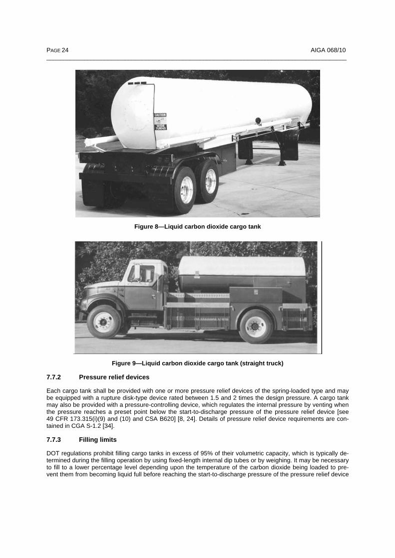
Figure 9—Liquid carbon dioxide cargo tank (straight truck)
7.7.2 Pressure relief devices
Each cargo tank shall be provided with one or more pressure relief devices of the spring-loaded type and may be equipped with a rupture disk-type device rated between 1.5 and 2 times the design pressure. A cargo tank may also be provided with a pressure-controlling device, which regulates the internal pressure by venting when the pressure reaches a preset point below the start-to-discharge pressure of the pressure relief device [see 49 CFR 173.315(i)(9) and (10) and CSA B620] [8, 24]. Details of pressure relief device requirements are con-tained in CGA S-1.2 [34].
7.7.3 Filling limits
DOT regulations prohibit filling cargo tanks in excess of 95% of their volumetric capacity, which is typically de-termined during the filling operation by using fixed-length internal dip tubes or by weighing. It may be necessary to fill to a lower percentage level depending upon the temperature of the carbon dioxide being loaded to pre-vent them from becoming liquid full before reaching the start-to-discharge pressure of the pressure relief device
AIGA 068/10 PAGE 25 ________________________________________________________________________________________
(see 49 CFR 173.315 and CSA B620) [8, 24]. A relationship of volume to temperature in containers is shown in Figure 5.
7.7.4 Retesting
Cargo tanks in carbon dioxide service shall be subjected to a hydrostatic or pneumatic pressure test by an au-thorized inspector at least once every 5 years. In the United States, external visual inspection is also required every 5 years. In Canada, external inspection is required annually, and internal inspection of TC 331 highway tanks is required every 5 years [24]. The retest pressure for a specification MC-330 and TC/MC-331 cargo tank shall be a minimum of 1.5 times the design pressure. A written report of the retest should be retained in the vehicle file for at least 5 years. The month and year of the last test shall be durably and legibly marked on the cargo tank jacket in letters at least 1.25 in (32 mm) high near the metal certification plate (see 49 CFR 180.407 and CSA B620) [8, 24].
MC-330 and TC/MC-331 cargo tanks in carbon dioxide service shall also be subjected to an annual leakage test. The month and year of the test shall be durably and legibly marked on the cargo tank jacket in letters at least 1.25 in (32 mm) high near the metal certification plate (see 49 CFR 180.407(h) and CSA B620) [8, 24].
A cargo tank that has been out of service for a period of 1 year or more shall be retested before being returned to service [see 49 CFR 180.407(b)(3) and CSA B620] [8, 24].
8 Storage and handling of carbon dioxide
8.1 Uninsulated cylinders
8.1.1 Storage precautions
Cylinders always should be stored in a definitely assigned location (see CGA P-1, Safe Handling of Com-pressed Gases in Containers) [35]. It is important to remember that liquid carbon dioxide in uninsulated cylin-ders is stored at about 850 psig (5860 kPa) at room temperature, and cylinder failure can result in a violent re-lease of energy. Carbon dioxide vapor is approximately 1.5 times heavier than air. Gas escaping from a cylin-der will tend to collect in low areas or confined spaces and can cause asphyxiation.
Cylinders should never be subjected to temperatures in excess of 125 °F (51.7 °C) because of the excessive pressure that will occur. Cylinders should never be stored in direct sunlight, near furnaces, radiators, or any other source of heat. Steel cylinders subjected to fire or high heat shall either be condemned or returned to the cylinder manufacturer for examination to determine their suitability for continued service. Aluminum cylinders that have been subjected to heat or fire shall not be used again. Temperatures in excess of 350 °F (177 °C) will irreversibly change the properties of the aluminum, and the cylinder shall be condemned (see CGA G-6.3) [28].
Cylinders shall not be dropped or otherwise subjected to abnormal mechanical shock that could damage the cylinder, valve, or pressure relief device. Cylinders should not be stored near elevators or gangways or in loca-tions where heavy moving objects may strike them or fall on them. Cylinders should be secured to a wall or other suitable structure to prevent them from falling over.
Cylinders should be stored in a dry, well-ventilated location above ground level. External corrosion can be the cause of cylinder failure, and cylinders should not be stored in plating rooms or other locations that may have a corrosive atmosphere.
8.1.2 Handling precautions
Personnel should be trained in the proper handling and use of carbon dioxide cylinders. They also should be made aware of the hazards involved when approved procedures are bypassed, altered, or ignored. For addi-tional information, see CGA G-6.3, CGA P-1, and CGA P-24 [28, 35, 20].
The internal pressure of carbon dioxide cylinders varies with ambient temperature. For example, under equilib-rium conditions at –40 °F (–40 °C) the pressure would be approximately 131 psig (900 kPa); and at 85 °F (29.4 °C) the pressure would be 1018 psig (7020 kPa). Extreme care should be exercised when connecting, disconnecting, filling, discharging, and maintaining cylinders.

PAGE 26 AIGA 068/10 ________________________________________________________________________________________
The piping system to the use point shall be designed to safely accommodate the pressures encountered. Pip-ing or tubing shall be adequately braced and protected from mechanical damage. Examples of acceptable pip-ing specifications are:
– Ferrous piping—ASTM Iron and Steel Products, Volume 01.06, and ASTM A53, Specifications for Pipe, Steel Black and Hot-Dipped, Zinc-Coated, Welded and Seamless [36, 37];
– Nonferrous piping—ASTM B88, Specification for Seamless Copper Water Tube [38];
– Flexible metallic hose—UL 536, Flexible Metal Hose [39].
Adequate pressure relief devices shall be provided where liquid carbon dioxide can become trapped (see 5.5).
CAUTION: Ordinary cast iron pipe and malleable iron and steel pipe conforming to ASTM A120 shall not be used because they might fracture upon impact, especially under cold conditions.
Gas pressure-reducing regulators should be specifically designed for carbon dioxide service. Neoprene, nylon, ethylene-propylene diene monomer (EPDM), and polytetrafluoroethylene (PTFE) are commonly used in both carbon dioxide regulators and cylinder valves. Avoid using materials that absorb carbon dioxide and swell or deform such as certain formulations of Buna-N and natural rubber. High consumption rates may require a regu-lator preheater.
The valves on empty cylinders should be tightly closed to prevent air or moisture from entering while they are being returned for refilling.
8.2 Insulated liquid cylinders
8.2.1 Storage precautions
Cylinders should always be stored in an assigned location. These cylinders are designed to vent carbon dioxide gas to limit the pressure as the contents warm. Therefore, the location shall be well ventilated, out of traffic pat-terns, and above ground away from cellars or low areas where the heavy carbon dioxide gas (1.5 times heavier than air) may collect. Storage should be away from excessive heat sources.
8.2.2 Handling precautions
Liquid carbon dioxide cylinders (liquid cylinders) have an inner container suspension system designed to mini-mize heat input. Liquid cylinders depend upon the vacuum in the insulation space to provide the required de-gree of insulation. Loss of this vacuum will cause excessive amounts of gaseous carbon dioxide to be vented through the pressure relief devices. In such cases, the liquid cylinder should be immediately moved outdoors and the liquid cylinder supplier should be notified. Liquid cylinders should never be subjected to shocks, falls, or impact and shall always be kept upright (see Figure 10).

AIGA 068/10 PAGE 27 ________________________________________________________________________________________
Figure 10—Insulated liquid carbon dioxide cylinder
Full liquid cylinders are very heavy and shall be moved only on a four-wheel cart designed for that purpose. Rolling of full liquid cylinders is extremely hazardous because, should the cylinder fall, the inner container might fail, releasing full pressure to the vacuum space causing a catastrophic failure of the outer shell. Also, a falling liquid cylinder can cause severe injuries from its weight alone.
Never lift a liquid cylinder by the handling ring because the ring is not designed for that purpose and could be damaged. If a cylinder must be moved with a hoist, forklift, etc., attach the hooks to the lifting lugs provided for that purpose using an appropriate spreader bar.
8.2.3 Operating precautions
Many liquid cylinders have a vaporizer in the vacuum space to provide gaseous carbon dioxide at near ambient temperatures. Should the use rate become excessive, the outer shell of the cylinder will frost heavily and the withdrawn carbon dioxide may become extremely cold. Never apply heat to the liquid cylinder to correct this condition; instead, reduce the use rate or manifold additional cylinders.
A liquid cylinder is equipped with a filling/liquid-use valve, a gas-use valve, a pressure-building valve, a vent valve, a pressure gauge, a liquid-level gauge, and various regulators and pressure relief devices. The gas- and liquid-use valves, the pressure-building valve, the liquid-level gauge, and the pressure gauge are the only de-vices intended for customer use.
8.3 Bulk liquid carbon dioxide storage containers (containers)
Containers shall be designed, constructed, and tested in accordance with the requirements of the ASME Boiler & Pressure Vessel Code (ASME Code), Section VIII, Division 1, current at the time the vessel is constructed (see Figure 11) [2].
Containers shall be designed and constructed to minimize the risk of overfilling. Containers shall never be al-lowed to become completely liquid full (see Table 6).
Containers shall be adequately insulated and may be equipped with refrigerating and vaporizing systems to maintain the pressure within the design pressure and temperature limitations. See Figure 12 for a typical piping schematic for carbon dioxide storage systems.
Carbon dioxide storage quantities greater than 10 000 lb (4536 kg) are covered in 40 CFR, Part 370, and by Title III of the Superfund Amendments and Reauthorization Act (SARA), Section 312, Tier II Hazardous

PAGE 28 AIGA 068/10 ________________________________________________________________________________________
Chemical Inventory Report requirements [40]. It is the responsibility of the user to file the appropriate govern-ment reports by March 1 of each calendar year. Tier II reports should be sent to the appropriate State Emer-gency Response Commission (SERC), the appropriate Local Emergency Planning Committee (LEPC), and the local fire department.
Figure 11—Bulk liquid carbon dioxide container
Equipment Symbols Valve number/sequence 1. Refrigeration system PI = Pressure indicator 2. Refrigeration coil LI = Level indicator 3. Pressure-building
vaporizer (optional) PS = Pressure switch
4. Manway 5. Fixed-end CGA fitting
V-1 Liquid process V-2 Liquid fill V-3 Vapor balance V-4 Vapor process V-5 Switching valve–3-way diverter
valve (shall conform to pressure loss requirements of ASME Code)
V-6 Vaporizer isolation V-7 Vaporizer blowdown V-8 Vaporizer pressure relief device
V-9 Instrumentation blowdown V-10 Instrumentation isolation V-11 Instrumentation equalization V-12 Instrumentation isolation V-13 Vaporizer isolation V-14 Vessel pressure relief device
350 psig (2410 kPa) set pressure. Discharge piped to weather pro-tected tee arrangement
V-15 Pressure control device 350 psig (2410 kPa)
Figure 12—Typical piping schematic for carbon dioxide storage system

AIGA 068/10 PAGE 29 ________________________________________________________________________________________
8.4 Pressure relief devices for stationary containers
8.4.1 General
Containers shall be equipped with properly sized pressure relief devices compatible with carbon dioxide. Sizing of the primary pressure relief device shall be sufficient to maintain safe pressure in the event of a major exter-nal heat input such as fire. See CGA S-1.3, Pressure Relief Device Standards–Part 3–Stationary Storage Con-tainers for Compressed Gases and the ASME Code for sizing requirements [41, 2].
The pressure relief device shall access the highest point in the vapor space in the container. Piping to the pres-sure relief device shall not pass through the liquid phase of the container to prevent the condensation of mois-ture or freezing of moisture in the pressure relief device. The maximum allowable pressure drop from the vapor phase of the container to the inlet of the relief device should not exceed 3% of start-to-discharge pressure 10.5 psig (72 kPa) for a MAWP of 350 psig (2410 kPa)] under full-flow condition [2].
Use of a three-way selector valve and pressure relief devices with external field test connections is recom-mended but not required. These allow for periodic maintenance and valve testing as required in CGA S-1.3 without removing the container from service [41].
Pressure relief device discharge piping shall be designed so it cannot accumulate moisture, water, ice, or any other foreign material that would restrict its proper operation.
Sizing and design of all pressure relief device discharge piping shall meet the requirements of Appendix M of the ASME Code and CGA S-1.3 [2, 41]. The maximum pressure restriction allowed on the pressure relief de-vice discharge piping is 10% of the start-to-discharge pressure. For example, the maximum allowable pressure (back pressure) in the discharge piping would be 35 psig (241 kPa) for a 350 psig (2410 kPa) pressure relief device setting.
A rupture disk-type pressure relief device may be used but is not recommended to meet sizing requirements. A ruptured disk will result in the complete depressurization of the container causing the formation of dry ice at –109.3 °F (–78.5 °C). To return the container to service, repressurize the container using one of CGA’s rec-ommended procedures (see CGA G-6.7) [6].
The pressure relief device shall be clearly marked to show the pressure and flow capacity at which it is set to operate. It shall have a means of sealing the start-to-discharge pressure adjustment and be ASME certified. It shall be located and arranged to prevent tampering or damage as much as possible.
The pressure relief device shall discharge into a well-ventilated area to prevent asphyxiation. Carbon dioxide is 1.5 times heavier than air and accumulates in low or poorly ventilated areas.
The use of an adjustable back-pressure regulator or bleeder valve is recommended but not required. It is typi-cally sized to maintain the container pressure due to normal heat input should the refrigeration unit fail. The pressure setting is above the normal operating pressure and below the pressure relief valve start-to-discharge pressure setting, typically 325 psig (2240 kPa).
8.4.2 Indoor installations
Most carbon dioxide containers are designed for outdoor installation. Indoor installations are discouraged, but if necessary, require increasing the pressure relief device capacity as required by CGA S-1.3 [41]. All pressure relief devices shall be piped externally to a safe location. Container fill connections as well as level and pres-sure gauges should be piped to an outdoor location readily accessible to the person responsible for filling the container with carbon dioxide. Monitoring carbon dioxide concentrations is recommended for all indoor installa-tions.
8.5 Refrigeration system
A mechanical refrigeration system may be used to maintain the desired operating pressure during periods of low usage or increased heat input.

PAGE 30 AIGA 068/10 ________________________________________________________________________________________
The refrigeration unit removes heat from the contents by condensing carbon dioxide vapor, which results in a corresponding decline in pressure. The refrigeration evaporator coil is installed in the vapor space of the con-tainer. The refrigeration system automatically operates to maintain a preset maximum pressure, typically 290 psig to 310 psig (2000 kPa to 2140 kPa). Failure of the refrigeration system could lead to a gradual loss of carbon dioxide vapor through the pressure relief system.
The refrigeration system is designed and sized based on the normal heat entry into the container as well as any extra heat load due to the process being used. Examples of other heat loads are a circulating loop or a cylinder filling pump returning liquid to the container.
8.6 Vaporizer system
A pressure-building vaporizing system may be required to maintain the desired operating pressure during peri-ods of vapor usage or high liquid withdrawal. A cooling effect takes place as product is withdrawn from the con-tainer resulting in a decrease of pressure and temperature.
The pressure-building vaporizer system is designed to prevent the pressure in the container from dropping be-low a preset value. A small portion of the liquid is vaporized and returned to the vapor space of the container.
The vaporizer should be sized for the expected vapor withdrawal rate. Typical electrically operated vaporizers range in capacities from 9 kW to 56 kW. Larger capacities are available using steam or hot water as the heat source.
The vaporizer system operates at preset pressures, typically 245 psig to 255 psig (1690 kPa to 1760 kPa), to maintain a preset minimum pressure.
CAUTION: Failure of the vaporizer system could cause the container temperature to drop below the minimum design metal temperature. Continued product withdrawal after such a failure could cause the contents of the container to convert to dry ice.
8.7 Transfer hoses
Hoses used in the transfer of liquid and gaseous carbon dioxide between containers, cargo tanks, and tank cars are typically elastomer hoses designed specifically for the transfer of liquid carbon dioxide. These hoses shall meet or exceed the requirements of CGA G-6.6, Standard for Elastomer-Type Carbon Dioxide Bulk Trans-fer Hose (see Figures 13 and 14) [42]. Hoses of this type are to be inspected and requalified for continued ser-vice once every 6 months with a recommended maximum service life of 4 years in accordance with CGA P-7, Standard for Requalification of Cargo Tank Hose Used in the Transfer of Carbon Dioxide Refrigerated Liquid [43].
Figure 13—Liquid cylinder fill hose

AIGA 068/10 PAGE 31 ________________________________________________________________________________________
Figure 14—Bulk liquid transfer hose
Hoses used in the transfer of liquid carbon dioxide into DOT-4L and TC-4LM specification liquid cylinders shall be designed with a MAWP of at least 1000 psig (6900 kPa) and a minimum design temperature of –65 °F (–53.9 °C). The hose material shall be compatible with the transfer of liquid carbon dioxide.
Hoses used in the transfer of carbon dioxide into uninsulated cylinders are recommended to be in accordance with CGA E-9, Standard for Flexible PTFE-Lined Pigtails for Compressed Gas Service [44]. Hoses used in the transfer of carbon dioxide should be restrained at the ends to prevent whipping in the event of a hose connec-tion failure.
8.8 Solid carbon dioxide (dry ice)
8.8.1 General
Dry ice in equilibrium with its vapor at 1 atmosphere is at –109.3 °F (–78.5 °C). It is typically used as an ex-pendable refrigerant, and it absorbs heat rapidly from its surroundings and sublimes into carbon dioxide gas. For additional information on dry ice and labeling, see CGA G-6.9 [5].
8.8.2 Storage boxes
Storage boxes for dry ice are well insulated on the bottom and sides with either an open or closed top. If the top can be tightly closed, the container shall be designed to prevent pressure buildup due to sublimation. Open-top boxes are usually covered with an insulating blanket fitted tightly enough at the edges to eliminate the intrusion of air while still allowing the escape of carbon dioxide vapor. Proper storage and shielding from moisture in the air minimizes the accumulation of frost.
8.8.3 Location of storage area
Dry ice storage boxes should be stored in a cool, well-ventilated area.
8.8.4 Handling precautions
Dry ice should not be handled with bare hands. Heavy insulated gloves are recommended. Dry ice blocks may be moved with steel tongs.
Dry ice should be disposed of only in an area that is not accessible to passers-by.
Do not transport dry ice in automobiles or other passenger vehicles without sufficient ventilation to prevent ex-cessive exposure of carbon dioxide vapors to the occupants. Driving with windows, trunk lids, and hatches open is recommended. Never leave dry ice in a parked passenger vehicle. Dry ice in a closed passenger vehi-cle can result in the accumulation of dangerous concentrations of carbon dioxide vapor. It can be safely trans-
PAGE 32 AIGA 068/10 ________________________________________________________________________________________
ported in closed cargo areas in trucks without special ventilation provided passengers are restricted to the truck cabs. Special shipping requirements are applicable when dry ice is transported by water or air (see 49 CFR 173.217 and TC regulations) [8, 9].
9 Carbon dioxide applications
9.1 Expendable refrigerants
– food freezing;
– chilling;
– transportation of chilled and frozen products;
– shrink fitting;
– environmental testing;
– cryogenic grinding;
– plastic blow mold chilling;
– rubber deflashing; and
– dry ice blast cleaning.
9.2 Carbonation
– soft drinks;
– beer and wine; and
– beverage dispensing.
9.3 Chemical reactant
– manufacturing of carbonates;
– methanol;
– urea; and
– foundry cores.
9.4 Pressurizing/solvent medium
– enhanced oil recovery;
– aerosol propellant; and
– blowing agents.
9.5 pH control
– potable water treatment; and
– swimming pool and caustic waste neutralization.
9.6 Fire suppression
9.7 Controlled atmospheres
– welding;
– shielding gas;
AIGA 068/10 PAGE 33 ________________________________________________________________________________________
– inerting and blanketing; and
– greenhouse atmospheric enrichment.
9.8 Other
– grain fumigation;
– medical respiratory therapy mixtures; and
– supercritical extraction.
10 References
Unless otherwise specified, the latest edition shall apply.
[1] CGA P-11, Metric Practice Guide for the Compressed Gas Industry, Compressed Gas Association, Inc., 4221 Walney Rd., 5th Floor, Chantilly, VA 20151. www.cganet.com
[2] ASME Boiler & Pressure Vessel Code, Sec. VIII, Div. 1, ASME International, Three Park Ave., New York, NY 10016. www.asme.org
[3] Quinn, E.L. and Jones, Charles L, Carbon Dioxide, pg. 97, American Chemical Society Monograph Series, Reinhold Publishing Corp., New York, NY 10036. www.umi.com
[4] CGA G-6.2, Commodity Specification for Carbon Dioxide, Compressed Gas Association, Inc., 4221 Walney Rd., 5th Floor, Chantilly, VA 20151. www.cganet.com
[5] CGAG-6.9, Dry Ice, Compressed Gas Association, Inc., 4221 Walney Rd., 5th Floor, Chantilly, VA 20151. www.cganet.com
[6] CGA G-6.7, Safe Handling of Liquid Carbon Dioxide Containers That Have Lost Pressure, Compressed Gas Association, Inc., 4221 Walney Rd., 5th Floor, Chantilly, VA 20151. www.cganet.com
[7] CGA G-6.1, Standard for Insulated Liquid Carbon Dioxide Systems at Consumer Sites, Compressed Gas Association, Inc., 4221 Walney Rd., 5th Floor, Chantilly, VA 20151. www.cganet.com
[8] Code of Federal Regulations, Title 49 (Transportation), U.S. Department of Transportation, U.S. Govern-ment Printing Office, Washington, DC 20402. www.gpoaccess.gov
[9] Transportation of Dangerous Goods Regulations, Transport Canada, Canadian Government Publishing, Public Works and Government Services Canada, Ottawa, ON K1A 0S9, Canada. www.tc.gc.ca
[10] CGA G-6.5, Standard for Small, Stationary, Insulated Carbon Dioxide Supply Systems, Compressed Gas Association, Inc., 4221 Walney Rd., 5th Floor, Chantilly, VA 20151. www.cganet.com
[11] CSA B340, Selection and Use of Cylinders, Spheres, Tubes, and Other Containers for the Transportation of Dangerous Goods, Class 2, Canadian Standards Association, 5060 Spectrum Way, Suite 100, Mississauga, ON L4W 5N6, Canada. www.csa.ca
[12] CGA SB-33, Static Electricity Hazards for Liquid or Solid Carbon Dioxide, Compressed Gas Association, Inc., 4221 Walney Rd., 5th Floor, Chantilly, VA 20151. www.cganet.com
[13] Lambertson, C.J., Carbon Dioxide Tolerance and Toxicity, 1974, Institute for Environmental Medicine, Uni-versity of Pennsylvania, Philadelphia, PA 19122. www.upenn.edu
[14] Code of Federal Regulations, Title 29 (Labor) Parts 1900-1999, Superintendent of Documents, U.S. Gov-ernment Printing Office, Washington, DC 20402. www.gpoaccess.gov

PAGE 34 AIGA 068/10 ________________________________________________________________________________________
[15] TLVs® and BEIs® Threshold Limit Values for Chemical Substances and Physical Agents & Biological Expo-sure Indices, American Conference of Governmental Industrial Hygienists, 1330 Kemper Meadow Dr., Cincin-nati, OH 45240. www.acgih.org
[16] CGA SB-15, Managing Hazards in Confined Work Spaces During Maintenance, Construction, and Similar Activities, Compressed Gas Association, Inc., 4221 Walney Rd., 5th Floor, Chantilly, VA 20151. www.cganet.com
[17] NFPA 704, Standard System for the Identification of the Hazards of Materials for Emergency Response, 2007 edition, National Fire Protection Association, One Batterymarch Park, Quincy, MA 02269. www.nfpa.org
NOTE—Selected portions of this document are reprinted with permission from NFPA 704-2007, Standard System for the Identification of the Hazards of Materials for Emergency Response, Copyright © 2007, National Fire Protection Association, Quincy, MA 02269. This reprinted material is not the complete and official position of the NFPA on the referenced subject, which is represented only by the standard in its entirety.
[18] Hazardous Materials Identification System® III Implementation Manual, Third Edition, National Paint and Coatings Association, American Labelmark Co. Inc., Labelmaster Division, 5724 N. Pulaski Rd., Chicago, IL 60646. www.paint.org
[19] CGA P-19, CGA Recommended Hazard Ratings for Compressed Gases, Compressed Gas Association, Inc., 4221 Walney Rd., 5th Floor, Chantilly, VA 20151. www.cganet.com
[20] CGA P-24, Guide to the Preparation of Material Safety Data Sheets, Compressed Gas Association, Inc., 4221 Walney Rd., 5th Floor, Chantilly, VA 20151. www.cganet.com
[21] Fire Protection Guide to Hazardous Materials, National Fire Protection Association, One Batterymarch Park, Quincy, MA 02269. www.nfpa.org
[22] CGSB 43.147–2005, Construction, Modification, Qualification, Maintenance, and Selection and Use of Means of Containment for the Handling, Offering for Transport, or Transport of Dangerous Goods by Rail, Ca-nadian General Standards Board, Place du Portage III–6B1, 11 Laurier St., Gatineau, QC K1A 1G6, Canada. www.pwgsc.gc.ca/cgsb
[23] CSA B339, Cylinders, Spheres, and Tubes for the Transportation of Dangerous Goods, Canadian Stan-dards Association, 5060 Spectrum Way, Suite 100, Mississauga, ON L4W 5N6, Canada. www.csa.ca
[24] CSA B620, Highway Tanks and Portable Tanks for the Transportation of Dangerous Goods, Canadian Standards Association, 5060 Spectrum Way, Suite 100, Mississauga, ON L4W 5N6, Canada. www.csa.ca
[25] CSA B622, Selection and Use of Highway Tanks, Multi-Unit Tank Car Tanks, and Portable Tanks for the Transportation of Dangerous Goods, Class 2, Canadian Standards Association, 5060 Spectrum Way, Suite 100, Mississauga, ON L4W 5N6, Canada. www.csa.ca
[26] CGA V-1, Standard for Compressed Gas Cylinder Valve Outlet and Inlet Connections, Compressed Gas Association, Inc., 4221 Walney Rd., 5th Floor, Chantilly, VA 20151. www.cganet.com
[27] CGA S-1.1, Pressure Relief Device Standards–Part 1–Cylinders for Compressed Gases, Compressed Gas Association, Inc., 4221 Walney Rd., 5th Floor, Chantilly, VA 20151. www.cganet.com
[28] CGA G-6.3, Carbon Dioxide Cylinder Filling and Handling Procedures, Compressed Gas Association, Inc., 4221 Walney Rd., 5th Floor, Chantilly, VA 20151. www.cganet.com
[29] CGA C-6, Standards for Visual Inspection of Steel Compressed Gas Cylinders, Compressed Gas Associa-tion, Inc., 4221 Walney Rd., 5th Floor, Chantilly, VA 20151. www.cganet.com
[30] CGA C-6.1, Standards for Visual Inspection of High Pressure Aluminum Compressed Gas Cylinders, Com-pressed Gas Association, Inc., 4221 Walney Rd., 5th Floor, Chantilly, VA 20151. www.cganet.com
[31] CGA C-8, Standard for Requalification of DOT-3HT, CTC-3HT, and TC-3HTM Seamless Steel Cylinders, Compressed Gas Association, Inc., 4221 Walney Rd., 5th Floor, Chantilly, VA 20151. www.cganet.com

AIGA 068/10 PAGE 35 ________________________________________________________________________________________
[32] CGA C-1, Methods for Hydrostatic Testing of Compressed Gas Cylinders, Compressed Gas Association, Inc., 4221 Walney Rd., 5th Floor, Chantilly, VA 20151. www.cganet.com
[33] CGA C-7, Guide to the Preparation of Precautionary Labeling and Marking of Compressed Gas Cylinders, Compressed Gas Association, Inc., 4221 Walney Rd., 5th Floor, Chantilly, VA 20151. www.cganet.com
[34] CGA S-1.2, Pressure Relief Device Standards–Part 2–Portable Containers for Compressed Gases, Com-pressed Gas Association, Inc., 4221 Walney Rd., 5th Floor, Chantilly, VA 20151. www.cganet.com
[35] CGA P-1, Safe Handling of Compressed Gas in Containers, Compressed Gas Association, Inc. 4221 Wal-ney Rd., 5th Floor, Chantilly, VA 20151. www.cganet.com
[36] ASTM Iron and Steel Products, Volume 01.06, "Coated Steel Products", ASTM International, 100 Barr Har-bor Dr., West Conshohocken, PA 19428. www.astm.org
[37] ASTM A53, Standard Specification for Pipe, Steel, Black and Hot-Dipped, Zinc-Coated, Welded and Seam-less, ASTM International, 100 Barr Harbor Dr., West Conshohocken, PA 19428. www.astm.org
[38] ASTM B88, Standard Specification for Seamless Copper Water Tube, ASTM International, 100 Barr Har-bor Dr., West Conshohocken, PA 19428. www.astm.org
[39] UL 536, Flexible Metallic Hose, Underwriter’s Laboratories, 333 Pfingsten Rd., Northbrook, IL 60062. www.ul.com
[40] Code of Federal Regulations, Title 40 (Protection of Environment), Part 370, Superfund Amendments and Reauthorization Act (SARA), U.S. Environmental Protection Agency, Ariel Rios Building, 1200 Pennsylvania Ave., N.W., Washington, DC 20460. www.gpoaccess.gov
[41] CGA S-1.3, Pressure Relief Device Standards–Part 3–Stationary Storage Containers for Compressed Gases, Compressed Gas Association, Inc., 4221 Walney Rd., 5th Floor, Chantilly, VA 20151. www.cganet.com
[42] CGA G-6.6, Standard for Elastomer-Type Carbon Dioxide Bulk Transfer Hose, Compressed Gas Associa-tion, Inc., 4221 Walney Rd., 5th Floor, Chantilly, VA 20151. www.cganet.com
[43] CGA P-7, Standard for Requalification of Cargo Tank Hose Used in the Transfer of Carbon Dioxide Refrig-erated Liquid, Compressed Gas Association, Inc., 4221 Walney Rd., 5th Floor, Chantilly, VA 20151. www.cganet.com
[44] CGA E-9, Standard for Flexible PTFE-Lined Pigtails for Compressed Gas Service, Compressed Gas Asso-ciation, Inc., 4221 Walney Rd., 5th Floor, Chantilly, VA 20151. www.cganet.com