Embed Size (px)
Citation preview
AICHE EPC PAPER #86G
Ethylene Producers’ Conference (EPC)
ETHYLENE CRACKING FURNACE BURNER APPLICATIONS OPERATING
WITH SIGNIFICANTLY LESS THAN 90 MG/NM3 NOX EMISSIONS
Authors
Mr. Rex Isaacs Director, Burner Products
Zeeco, Inc.
Mr. Engui ZHANG
Deputy Director, Production Division Ⅳ
PetroChina Sichuan Petrochemical Co.,Ltd.
Mr. Mingjiu LI Deputy Chief Engineer
PetroChina Sichuan Petrochemical Co.,Ltd.
Mr. Shaowei MA
Cracking Furnace Process Engineer, Production Division Ⅳ
PetroChina Sichuan Petrochemical Co.,Ltd.
Mr. Jingyao LI
Director, Production Division Ⅳ
PetroChina Sichuan Petrochemical Co.,Ltd.
Presenter
Mr. Ryan Roberts Manager Project Management, Process Burners
Zeeco, Inc.
Prepared for Presentation at the 2016 Spring National Meeting Houston, TX, April 11-14, 2016
AIChE and the EPC shall not be responsible for statements or opinions contained in papers or printed in its publications.
Authors
Mr. Rex Isaacs Director Burner, Products,
Zeeco, Inc. Mr. Engui ZHANG
Deputy Director, Production Division Ⅳ
PetroChina Sichuan Petrochemical Co.,Ltd. Mr. Mingjiu LI
Deputy Chief Engineer, PetroChina Sichuan Petrochemical Co.,Ltd.
Mr. Shaowei MA
Cracking Furnace Process Engineer, Production Division Ⅳ,
PetroChina Sichuan Petrochemical Co.,Ltd. Mr. Jingyao LI
Director, Production Division Ⅳ
PetroChina Sichuan Petrochemical Co.,Ltd.
Abstract
This abstract will focus on the field results of eight ethylene cracking furnaces which use Zeeco GLSF Enhanced Jet burners at PetroChina Sichuan Petrochemical Company Limited (SPC) which achieve field measured NOx emissions significantly less than 90 mg/Nm3. Zeeco has found that using ultra low emissions burners in ethylene cracking applications is prove an economical solution for achieving NOx levels lower than 90 mg/Nm3 from existing fired equipment. Providing a next generation low NOx burner footprint that fits into ethylene cracking applications can be challenging in many applications. Ultralow NOx burner flame pattern(s) or profile(s) that can operate properly within the required burner-to-burner spacing
and heat flux limitations has also proven to be a challenge.
This paper will focus on an application using the GLSF Enhanced Jet Flat Flame Burner model where NOx emissions averaged around 50 mg/Nm3 in the field. The furnace field measured NOx emissions ranged between 35 mg/Nm3 (17 ppmv) to 65 mg/Nm3 (32 ppmv) at designed heat release. The GLSF Enhanced Jet floor burners utilize the basic “free-jet” method of mixing fuel gas and inert products of combustion to form a new combustible mixture before entering the combustion air stream. The resulting mixture burns at a lower adiabatic flame
temperature, resulting in lower thermal NOx production.
Zeeco developed this ultra low NOx emissions burner technology to provide a very small mechanical footprint and excellent heat flux profile without flame-to-flame interaction or flame rollover. Flame interaction between burners can cause flame impingement upon the process tubes and increased emissions. Flame impingement can result in shorter run lengths and
higher tube metal temperatures, problematic issues in prolonged ethylene production.
In conclusion, Zeeco and PetroChina Sichuan Petrochemical Company Limited (SPC) will co-author the paper and provide specific application details and the resulting field emission test results. This paper will focus on an application which uses the GLSF Flat Flame Enhanced Jet Burner design in eight ethylene cracking furnace which achieved significantly less than 90 mg/Nm3 in the field. This application will show that the field measured NOx emissions were between 35 mg/Nm3 (17 ppmv) to 65 mg/Nm3 (32 ppmv) at designed heat release for this
highlighted project.
Introduction
Achieving ultra low emissions less than 90 mg/Nm3 can be problematic in ethylene cracking applications. Often, the methods used to reduce NOx emissions result in longer flames, which can cause flame rollover toward the furnace tubes. Flame rollover issues can lead to flame impingement on the furnace tubes, resulting in hotspots. Such localized high temperatures within the tubes can cause premature coking and lead to shorter periods between de-coking and reduced ethylene production. For the past decade, Zeeco has worked on many applications where the number of floor burners increased, meaning the burners had to move closer together. Even in these situations, using the right technology helps avoid problematic occurrences such as flame rollover or flame interaction.
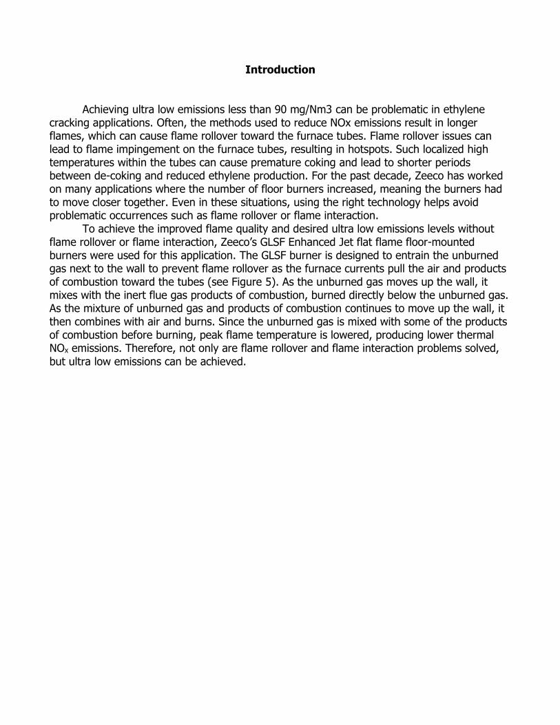
To achieve the improved flame quality and desired ultra low emissions levels without flame rollover or flame interaction, Zeeco’s GLSF Enhanced Jet flat flame floor-mounted burners were used for this application. The GLSF burner is designed to entrain the unburned gas next to the wall to prevent flame rollover as the furnace currents pull the air and products of combustion toward the tubes (see Figure 5). As the unburned gas moves up the wall, it mixes with the inert flue gas products of combustion, burned directly below the unburned gas. As the mixture of unburned gas and products of combustion continues to move up the wall, it then combines with air and burns. Since the unburned gas is mixed with some of the products of combustion before burning, peak flame temperature is lowered, producing lower thermal NOx emissions. Therefore, not only are flame rollover and flame interaction problems solved,
but ultra low emissions can be achieved.
Figure 1: The burner is designed so the gas stays next to the wall. Therefore, when the furnace currents pull the air toward the tubes, the gas and flame remain next to the wall with
no flame rollover.
Description of Application
GLSF Enhanced Jet burners were installed in eight new ethylene cracking furnaces.
Seven furnaces are twin cell furnaces with 64 burners per furnace. The eighth furnace is a single cell furnace with 24 burners.
Furnaces: 210-F-1110/20/30/40/50/60/70
Each furnace required 64 hearth (bottom) burners. Since the furnaces are a twin cell design, each cell included 32 burners. Each cell has 16 burners mounted on each side of the tubes located in the center of the furnace. The floor burners were designed to fire up the furnace wall, which in turn, radiates heat to be absorbed by the furnace tubes. Since the burners fire directly on the wall, the wall transfers heat to the process tubes that are located in
the center of the cracking heater.
Furnaces: 210-F-1180 This furnace required 24 hearth (bottom) burners. Since the furnace is a single cell
design. The furnace has 12 burners mounted on each side of the tubes located in the center of the furnace. The floor burners were designed to fire up the furnace wall, which in turn, radiates heat to be absorbed by the furnace tubes. Since the burners fire directly on the wall, the wall transfers heat to the process tubes that are located in the center of the cracking heater.
In summary, the hearth burners provide most of the heat while the radiant wall burners are the remaining heat release. In order for the heater to work properly, the hearth burners
must provide an even heat flux profile where the tubes are located.
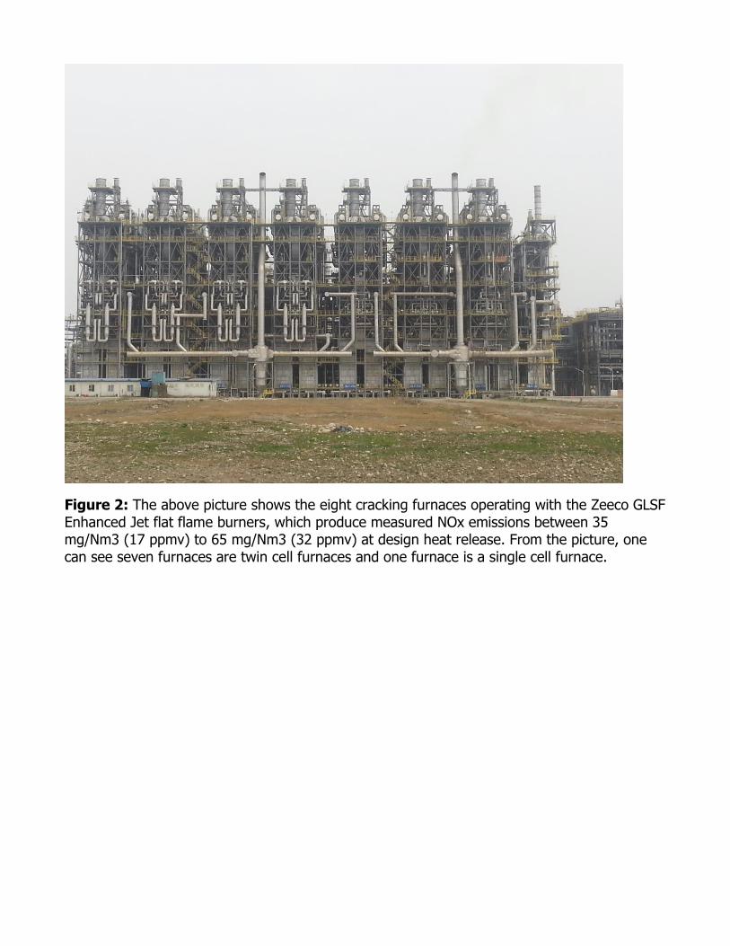
Figure 2: The above picture shows the eight cracking furnaces operating with the Zeeco GLSF Enhanced Jet flat flame burners, which produce measured NOx emissions between 35 mg/Nm3 (17 ppmv) to 65 mg/Nm3 (32 ppmv) at design heat release. From the picture, one can see seven furnaces are twin cell furnaces and one furnace is a single cell furnace.
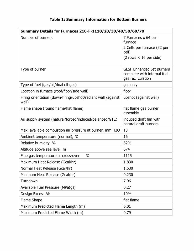
Table 1: Summary Information for Bottom Burners
Summary Details for Furnaces 210-F-1110/20/30/40/50/60/70
Number of burners 7 Furnaces x 64 per furnace
2 Cells per furnace (32 per cell)
(2 rows × 16 per side)
Type of burner GLSF Enhanced Jet Burners complete with internal fuel gas recirculation
Type of fuel (gas/oil/dual oil-gas) gas only
Location in furnace (roof/floor/side wall) floor
Firing orientation (down-firing/upshot/radiant wall /against wall)
upshot (against wall)
Flame shape (round flame/flat flame) flat flame gas burner assembly
Air supply system (natural/forced/induced/balanced/GTE) induced draft fan with natural draft burners
Max. available combustion air pressure at burner, mm H2O 13
Ambient temperature (normal), ℃ 16
Relative humidity, % 82%
Altitude above sea level, m 674
Flue gas temperature at cross-over ℃ 1115
Maximum Heat Release (Gcal/hr) 1.830
Normal Heat Release (Gcal/hr) 1.530
Minimum Heat Release (Gcal/hr) 0.230
Turndown 7.96
Available Fuel Pressure (MPa(g)) 0.27
Design Excess Air 10%
Flame Shape flat flame
Maximum Predicted Flame Length (m) 6.01
Maximum Predicted Flame Width (m) 0.79
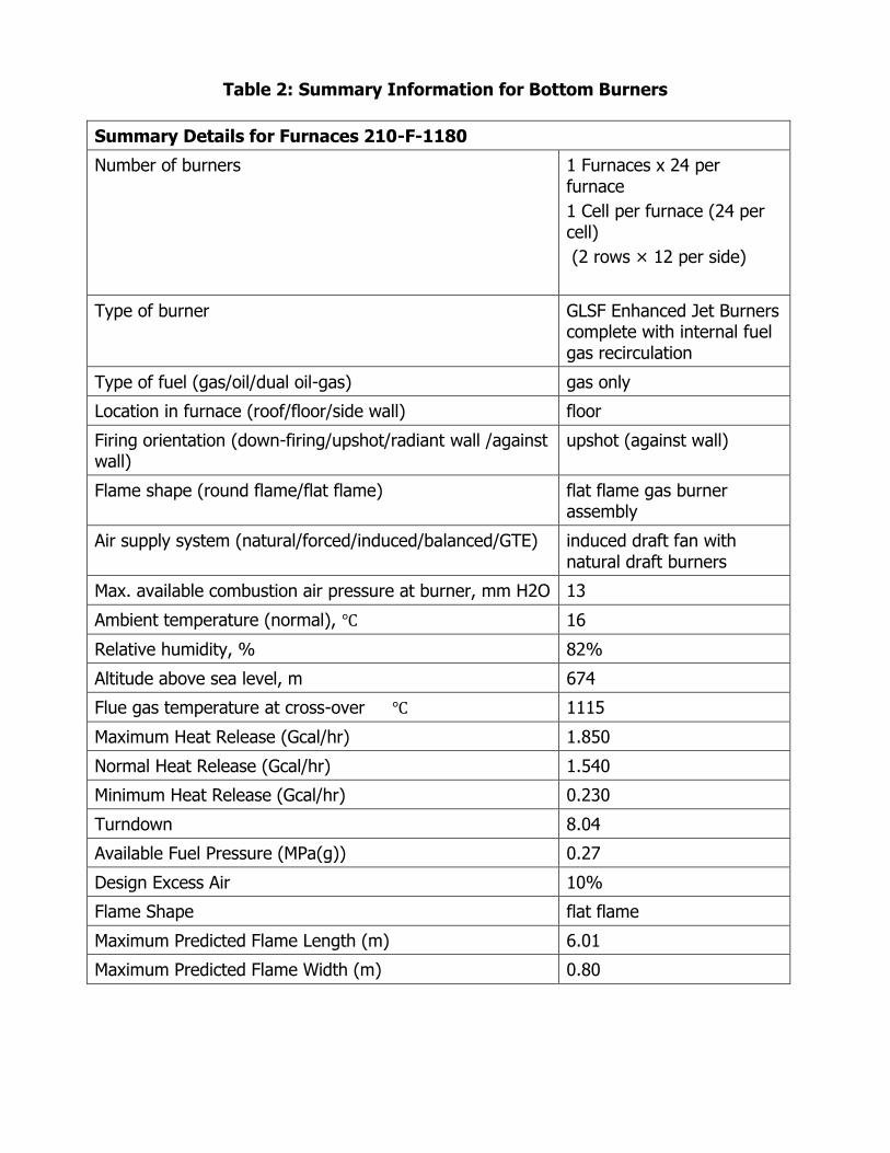
Table 2: Summary Information for Bottom Burners
Summary Details for Furnaces 210-F-1180
Number of burners 1 Furnaces x 24 per furnace
1 Cell per furnace (24 per cell)
(2 rows × 12 per side)
Type of burner GLSF Enhanced Jet Burners complete with internal fuel gas recirculation
Type of fuel (gas/oil/dual oil-gas) gas only
Location in furnace (roof/floor/side wall) floor
Firing orientation (down-firing/upshot/radiant wall /against wall)
upshot (against wall)
Flame shape (round flame/flat flame) flat flame gas burner assembly
Air supply system (natural/forced/induced/balanced/GTE) induced draft fan with natural draft burners
Max. available combustion air pressure at burner, mm H2O 13
Ambient temperature (normal), ℃ 16
Relative humidity, % 82%
Altitude above sea level, m 674
Flue gas temperature at cross-over ℃ 1115
Maximum Heat Release (Gcal/hr) 1.850
Normal Heat Release (Gcal/hr) 1.540
Minimum Heat Release (Gcal/hr) 0.230
Turndown 8.04
Available Fuel Pressure (MPa(g)) 0.27
Design Excess Air 10%
Flame Shape flat flame
Maximum Predicted Flame Length (m) 6.01
Maximum Predicted Flame Width (m) 0.80
Comparison to Low Emissions Burners
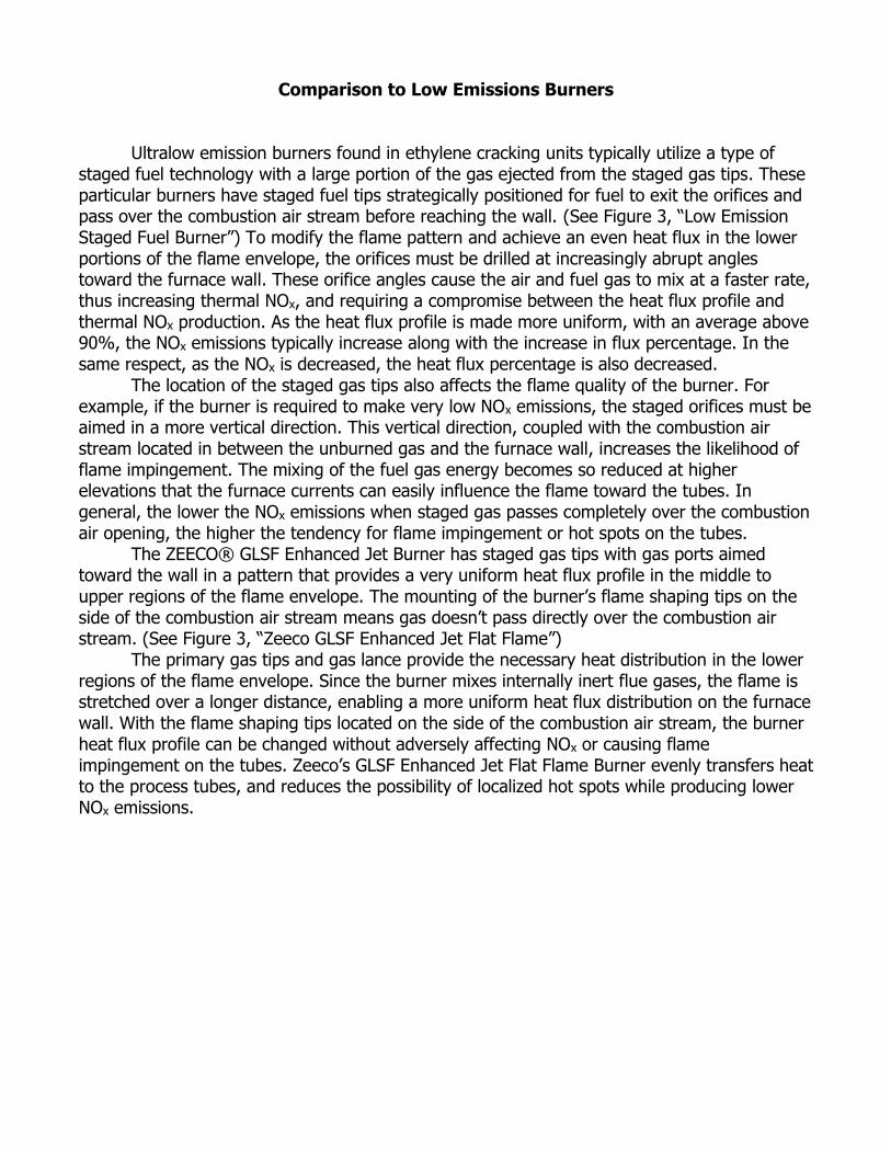
Ultralow emission burners found in ethylene cracking units typically utilize a type of staged fuel technology with a large portion of the gas ejected from the staged gas tips. These particular burners have staged fuel tips strategically positioned for fuel to exit the orifices and pass over the combustion air stream before reaching the wall. (See Figure 3, “Low Emission Staged Fuel Burner”) To modify the flame pattern and achieve an even heat flux in the lower portions of the flame envelope, the orifices must be drilled at increasingly abrupt angles toward the furnace wall. These orifice angles cause the air and fuel gas to mix at a faster rate, thus increasing thermal NOx, and requiring a compromise between the heat flux profile and thermal NOx production. As the heat flux profile is made more uniform, with an average above 90%, the NOx emissions typically increase along with the increase in flux percentage. In the same respect, as the NOx is decreased, the heat flux percentage is also decreased.
The location of the staged gas tips also affects the flame quality of the burner. For example, if the burner is required to make very low NOx emissions, the staged orifices must be aimed in a more vertical direction. This vertical direction, coupled with the combustion air stream located in between the unburned gas and the furnace wall, increases the likelihood of flame impingement. The mixing of the fuel gas energy becomes so reduced at higher elevations that the furnace currents can easily influence the flame toward the tubes. In general, the lower the NOx emissions when staged gas passes completely over the combustion air opening, the higher the tendency for flame impingement or hot spots on the tubes.
The ZEECO® GLSF Enhanced Jet Burner has staged gas tips with gas ports aimed toward the wall in a pattern that provides a very uniform heat flux profile in the middle to upper regions of the flame envelope. The mounting of the burner’s flame shaping tips on the side of the combustion air stream means gas doesn’t pass directly over the combustion air stream. (See Figure 3, “Zeeco GLSF Enhanced Jet Flat Flame”)
The primary gas tips and gas lance provide the necessary heat distribution in the lower regions of the flame envelope. Since the burner mixes internally inert flue gases, the flame is stretched over a longer distance, enabling a more uniform heat flux distribution on the furnace wall. With the flame shaping tips located on the side of the combustion air stream, the burner heat flux profile can be changed without adversely affecting NOx or causing flame impingement on the tubes. Zeeco’s GLSF Enhanced Jet Flat Flame Burner evenly transfers heat to the process tubes, and reduces the possibility of localized hot spots while producing lower NOx emissions.
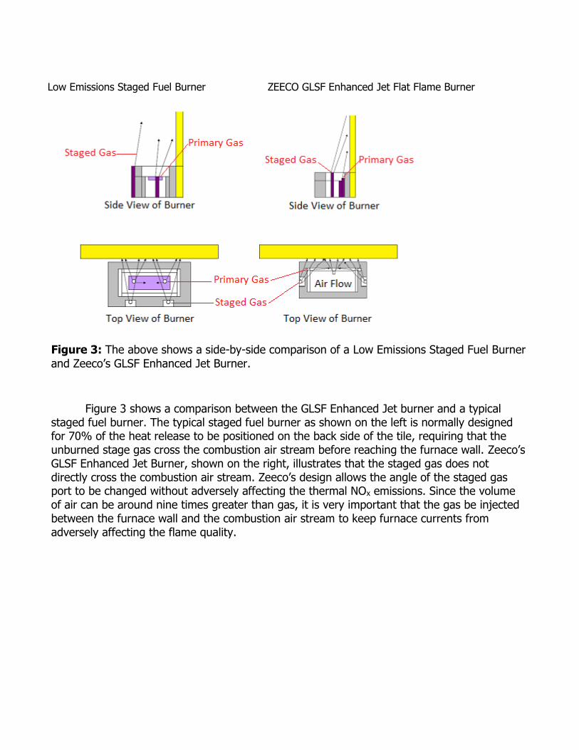
Figure 3: The above shows a side-by-side comparison of a Low Emissions Staged Fuel Burner
and Zeeco’s GLSF Enhanced Jet Burner.
Figure 3 shows a comparison between the GLSF Enhanced Jet burner and a typical staged fuel burner. The typical staged fuel burner as shown on the left is normally designed for 70% of the heat release to be positioned on the back side of the tile, requiring that the unburned stage gas cross the combustion air stream before reaching the furnace wall. Zeeco’s GLSF Enhanced Jet Burner, shown on the right, illustrates that the staged gas does not directly cross the combustion air stream. Zeeco’s design allows the angle of the staged gas port to be changed without adversely affecting the thermal NOx emissions. Since the volume of air can be around nine times greater than gas, it is very important that the gas be injected between the furnace wall and the combustion air stream to keep furnace currents from adversely affecting the flame quality.
Low Emissions Staged Fuel Burner ZEECO GLSF Enhanced Jet Flat Flame Burner
Description of Thermal NOx Creation and Reduction
In order to understand why the GLSF Enhanced Jet Flat Flame Burner design was selected, formation of thermal NOx emissions must first be examined. For gaseous fuels with no fuel-bound nitrogen (N2), thermal NOx is the primary contributor to overall NOx production. Thermal NOx is produced when flame temperatures reach a high enough level to “break” the
covalent N2 bond apart, allowing the “free” nitrogen atoms to bond with oxygen to form NOx.
Stoichiometric Equation describing typical combustion in a natural gas fired burner
Methane & Air with Excess Air
2CH4 + 4 (XA) O2 + 15 (XR) N2 ---> 2CO2 + 4H2O + (XA) 15N2 + (XR) O2
Natural air is comprised of 21% O2 and 79% N2. Combustion occurs when O2 reacts and combines with fuel (typically hydrocarbon). However, the temperature of combustion is not normally high enough to break all the N2 bonds. So, a majority of nitrogen in the air stream passes through the combustion process and remains diatomic nitrogen (N2) in the inert combustion products. Very little N2 is able to reach high enough temperatures in the high intensity regions of the flame to break apart and form “free” nitrogen. If the covalent nitrogen bond is broken, the “free” nitrogen is available to bond with other atoms. Basic chemistry dictates that free nitrogen, or nitrogen radicals, will react to other atoms or molecules that can accept them to create a more stable atom. Of the possible reactions with the products of combustion, free nitrogen will most likely bond with other free nitrogen to form N2. However, if a free nitrogen atom is not available, the free nitrogen will react with the oxygen atoms to form thermal NOx. As the flame temperature increases, the stability of the N2 covalent bond decreases, allowing the formation of free nitrogen and subsequently increasing thermal NOx. Burner designers can reduce overall NOx emissions by decreasing the peak flame temperature, which can reduce the formation of free nitrogen available to form thermal NOx.
The varied requirements of refining and petrochemical processes entail the use of numerous types and configurations of burners. The method utilized to lower NOx emissions can differ by application. However, thermal NOx reduction is generally achieved by delaying the rate of combustion. Since the combustion process is a reaction between oxygen and fuel, the objective of delayed combustion is to reduce the rate at which the fuel and oxygen mix and burn. The faster the oxygen and fuel gas mix, the faster the rate of combustion and higher the peak flame temperature. Figure 4 plots Peak Flame Temperature against Thermal NOx created. NOx emissions increase as the adiabatic flame temperature increases. Slowing the combustion reaction reduces the flame temperature, which results in lower thermal NOx emissions. The challenge in achieving lower thermal NOx emissions is not the theory; however, it is in retrofitting the latest burner technologies into older existing furnaces without adding expensive external components or processes.
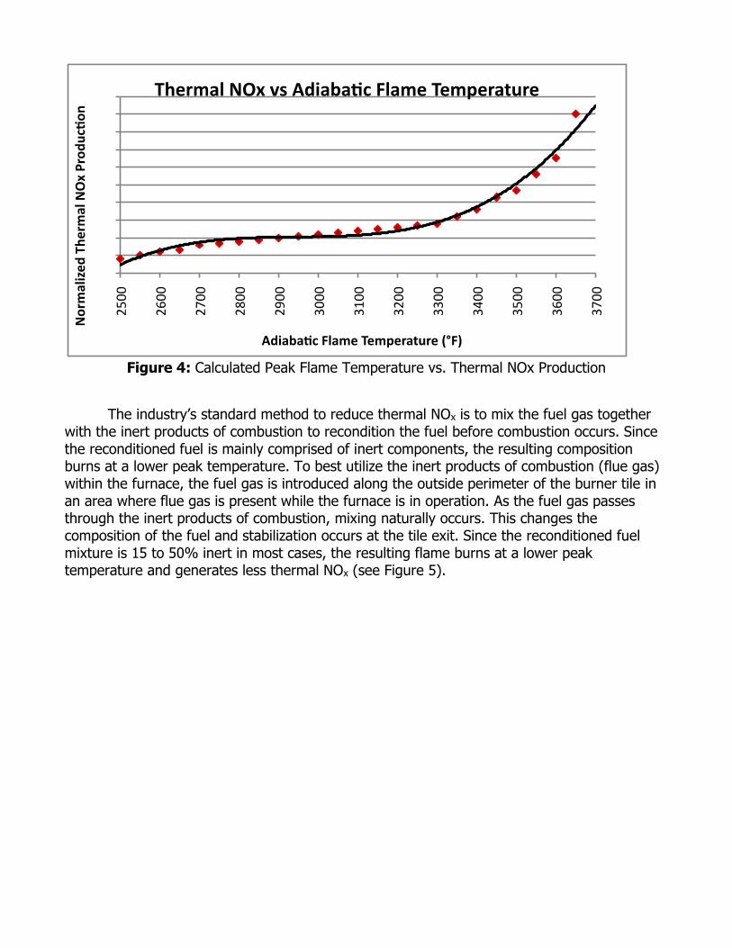
Figure 4: Calculated Peak Flame Temperature vs. Thermal NOx Production
The industry’s standard method to reduce thermal NOx is to mix the fuel gas together
with the inert products of combustion to recondition the fuel before combustion occurs. Since the reconditioned fuel is mainly comprised of inert components, the resulting composition burns at a lower peak temperature. To best utilize the inert products of combustion (flue gas) within the furnace, the fuel gas is introduced along the outside perimeter of the burner tile in an area where flue gas is present while the furnace is in operation. As the fuel gas passes through the inert products of combustion, mixing naturally occurs. This changes the composition of the fuel and stabilization occurs at the tile exit. Since the reconditioned fuel mixture is 15 to 50% inert in most cases, the resulting flame burns at a lower peak temperature and generates less thermal NOx (see Figure 5).
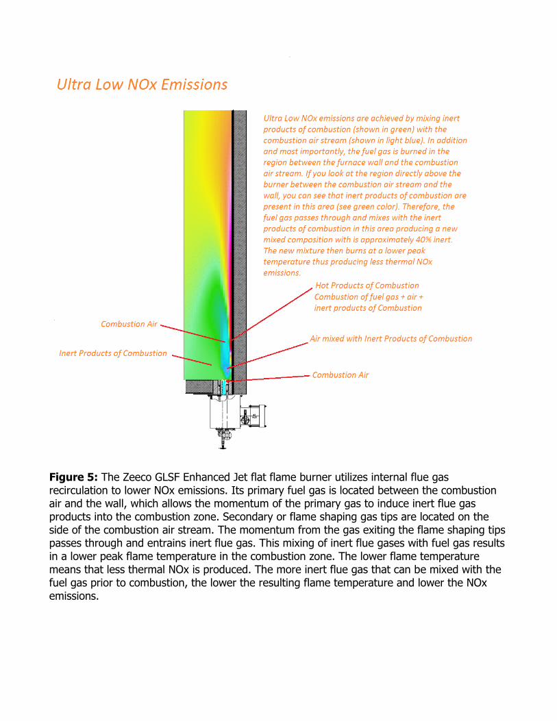
Figure 5: The Zeeco GLSF Enhanced Jet flat flame burner utilizes internal flue gas recirculation to lower NOx emissions. Its primary fuel gas is located between the combustion air and the wall, which allows the momentum of the primary gas to induce inert flue gas products into the combustion zone. Secondary or flame shaping gas tips are located on the side of the combustion air stream. The momentum from the gas exiting the flame shaping tips passes through and entrains inert flue gas. This mixing of inert flue gases with fuel gas results in a lower peak flame temperature in the combustion zone. The lower flame temperature means that less thermal NOx is produced. The more inert flue gas that can be mixed with the fuel gas prior to combustion, the lower the resulting flame temperature and lower the NOx emissions.
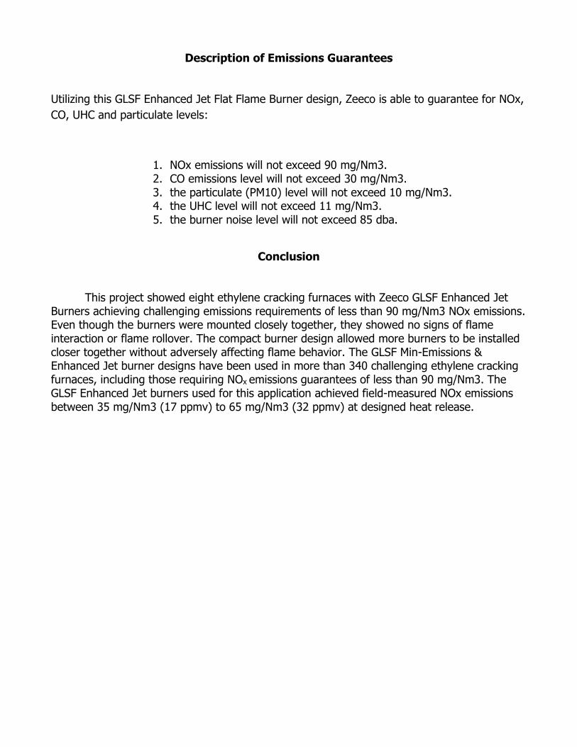
Description of Emissions Guarantees
Utilizing this GLSF Enhanced Jet Flat Flame Burner design, Zeeco is able to guarantee for NOx,
CO, UHC and particulate levels:
1. NOx emissions will not exceed 90 mg/Nm3. 2. CO emissions level will not exceed 30 mg/Nm3. 3. the particulate (PM10) level will not exceed 10 mg/Nm3. 4. the UHC level will not exceed 11 mg/Nm3. 5. the burner noise level will not exceed 85 dba.
Conclusion
This project showed eight ethylene cracking furnaces with Zeeco GLSF Enhanced Jet
Burners achieving challenging emissions requirements of less than 90 mg/Nm3 NOx emissions. Even though the burners were mounted closely together, they showed no signs of flame interaction or flame rollover. The compact burner design allowed more burners to be installed closer together without adversely affecting flame behavior. The GLSF Min-Emissions & Enhanced Jet burner designs have been used in more than 340 challenging ethylene cracking furnaces, including those requiring NOx emissions guarantees of less than 90 mg/Nm3. The GLSF Enhanced Jet burners used for this application achieved field-measured NOx emissions between 35 mg/Nm3 (17 ppmv) to 65 mg/Nm3 (32 ppmv) at designed heat release.