Embed Size (px)
Citation preview
480
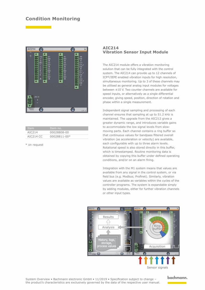
Acquisition
Results
Analysis
History, logs, storage,
process values
History, logs, storage,
process values
Sensor signals
Ring buffer
Condition Monitoring
AIC214 Vibration Sensor Input Module
The AIC214 module offers a vibration monitoring solution that can be fully integrated with the control system. The AIC214 can provide up to 12 channels of ICP®/IEPE enabled vibration inputs for high resolution, simultaneous monitoring. Up to 3 of these channels may be utilised as general analog input modules for voltages between ±10 V. Two counter channels are available for speed inputs, or alternatively as a single differential encoder, giving speed, position, direction of rotation and phase within a single measurement.
Independent signal sampling and processing of each channel ensures that sampling at up to 51.2 kHz is maintained. The upgrade from the AIC212 gives a greater dynamic range, and introduces variable gains to accommodate the low signal levels from slow- moving parts. Each channel contains a ring buffer so that continuous values for bandpass filtered overall vibration (as acceleration or velocity) are available, each configurable with up to three alarm levels. Rotational speed is also stored directly in this buffer, which is timestamped. Routine monitoring data is obtained by copying this buffer under defined operating conditions, and/or on an alarm firing.
Integration with the M1 system means that values are available from any signal in the control system, or via field bus (e.g. Modbus; Profinet). Similarly, vibration values are available as variables within the cycles of the controller programs. The system is expandable simply by adding modules, either for further vibration channels or other input types.
Item Item no.AIC214 00028808-00AIC214 CC 00028811-00*
* on request
System Overview • Bachmann electronic GmbH • 11/2019 • Specification subject to change – the product’s characteristics are exclusively governed by the data of the respective user manual.
481
Remote Monitoring (Optional)
Local Network
Condition Monitoring
WebLogServer
Fieldbus / Ethernet Fieldbus / Ethernet
Company network
Internet Internet Internet
Fieldbus / Ethernet
Sensor signals
Company network Company network
Sensor signals
Sensor signals
Industrial Control System
Condition Monitoring
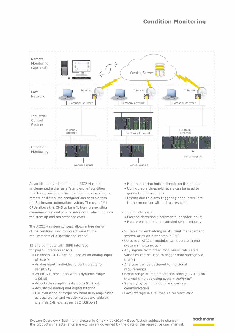
As an M1 standard module, the AIC214 can be implemented either as a “stand-alone” condition monitoring system, or incorporated into the various remote or distributed configurations possible with the Bachmann automation system. The use of M1 CPUs allows this CMS to benefit from pre-existing communication and service interfaces, which reduces the start-up and maintenance costs.
The AIC214 system concept allows a free design of the condition monitoring software to the requirements of a specific application.
12 analog inputs with IEPE interface for piezo vibration sensors:
• Channels 10-12 can be used as an analog input of ±10 V
• Analog inputs individually configurable for sensitivity
• 24 bit A-D resolution with a dynamic range ≥ 96 dB
• Adjustable sampling rate up to 51.2 kHz• Adjustable analog and digital filtering• Full evaluation of frequency band RMS amplitudes
as acceleration and velocity values available on channels 1-8, e.g. as per ISO 10816-21
• High-speed ring buffer directly on the module• Configurable threshold levels can be used to
generate alarm signals• Events due to alarm triggering send interrupts
to the processor with a 1 μs response
2 counter channels:• Position detection (incremental encoder input)• Rotary encoder signal sampled synchronously
• Suitable for embedding in M1 plant management system or as an autonomous CMS
• Up to four AIC214 modules can operate in one system simultaneously
• Any signals from other modules or calculated variables can be used to trigger data storage via the M1
• Analyses can be designed to individual requirements
• Broad range of implementation tools (C, C++) on the real-time operating system VxWorks®
• Synergy by using fieldbus and service communication
• Local storage in CPU module memory card
System Overview • Bachmann electronic GmbH • 11/2019 • Specification subject to change – the product’s characteristics are exclusively governed by the data of the respective user manual.
482
Condition Monitoring
AIC214
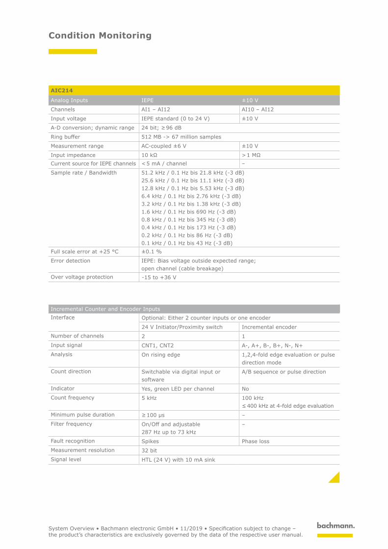
Analog Inputs IEPE ±10 V
Channels AI1 – AI12 AI10 – AI12
Input voltage IEPE standard (0 to 24 V) ±10 V
A-D conversion; dynamic range 24 bit; ≥ 96 dB
Ring buffer 512 MB -> 67 million samples
Measurement range AC-coupled ±6 V ±10 V
Input impedance 10 kΩ > 1 MΩCurrent source for IEPE channels < 5 mA / channel –
Sample rate / Bandwidth 51.2 kHz / 0.1 Hz bis 21.8 kHz (-3 dB)25.6 kHz / 0.1 Hz bis 11.1 kHz (-3 dB)12.8 kHz / 0.1 Hz bis 5.53 kHz (-3 dB)6.4 kHz / 0.1 Hz bis 2.76 kHz (-3 dB)3.2 kHz / 0.1 Hz bis 1.38 kHz (-3 dB)1.6 kHz / 0.1 Hz bis 690 Hz (-3 dB)0.8 kHz / 0.1 Hz bis 345 Hz (-3 dB)0.4 kHz / 0.1 Hz bis 173 Hz (-3 dB)0.2 kHz / 0.1 Hz bis 86 Hz (-3 dB)0.1 kHz / 0.1 Hz bis 43 Hz (-3 dB)
Full scale error at +25 °C ±0.1 %
Error detection IEPE: Bias voltage outside expected range; open channel (cable breakage)
Over voltage protection -15 to +36 V
Incremental Counter and Encoder InputsInterface Optional: Either 2 counter inputs or one encoder
24 V Initiator/Proximity switch Incremental encoder
Number of channels 2 1Input signal CNT1, CNT2 A-, A+, B-, B+, N-, N+Analysis On rising edge 1,2,4-fold edge evaluation or pulse
direction modeCount direction Switchable via digital input or
softwareA/B sequence or pulse direction
Indicator Yes, green LED per channel NoCount frequency 5 kHz 100 kHz
≤ 400 kHz at 4-fold edge evaluationMinimum pulse duration ≥ 100 µs –Filter frequency On/Off and adjustable
287 Hz up to 73 kHz–
Fault recognition Spikes Phase lossMeasurement resolution 32 bitSignal level HTL (24 V) with 10 mA sink
System Overview • Bachmann electronic GmbH • 11/2019 • Specification subject to change – the product’s characteristics are exclusively governed by the data of the respective user manual.
483
Condition Monitoring
AIC214
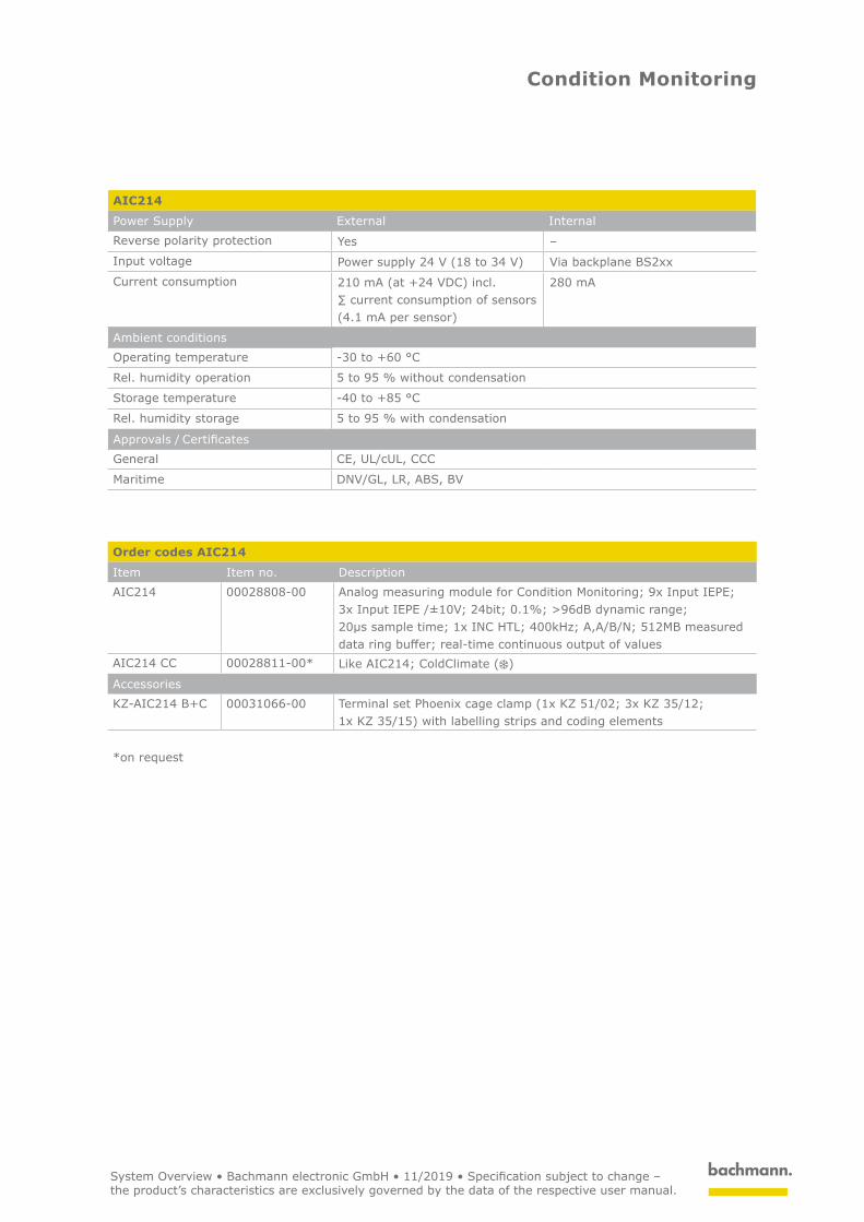
Power Supply External InternalReverse polarity protection Yes –Input voltage Power supply 24 V (18 to 34 V) Via backplane BS2xxCurrent consumption 210 mA (at +24 VDC) incl.
∑ current consumption of sensors (4.1 mA per sensor)
280 mA
Ambient conditions Operating temperature -30 to +60 °C
Rel. humidity operation 5 to 95 % without condensation
Storage temperature -40 to +85 °C
Rel. humidity storage 5 to 95 % with condensation
Approvals / CertificatesGeneral CE, UL/cUL, CCC
Maritime DNV/GL, LR, ABS, BV
Order codes AIC214
Item Item no. DescriptionAIC214 00028808-00 Analog measuring module for Condition Monitoring; 9x Input IEPE;
3x Input IEPE /±10V; 24bit; 0.1%; >96dB dynamic range; 20μs sample time; 1x INC HTL; 400kHz; A,A/B/N; 512MB measured data ring buffer; real-time continuous output of values
AIC214 CC 00028811-00* Like AIC214; ColdClimate ( )
AccessoriesKZ-AIC214 B+C 00031066-00 Terminal set Phoenix cage clamp (1x KZ 51/02; 3x KZ 35/12;
1x KZ 35/15) with labelling strips and coding elements
*on request
System Overview • Bachmann electronic GmbH • 11/2019 • Specification subject to change – the product’s characteristics are exclusively governed by the data of the respective user manual.