Embed Size (px)
Citation preview
Standard
AIAA S-133-7-201X
S-102.2.5-2009
Space Plug-and-Play Architecture Standard
Ontology
AIAA standards are copyrighted by the American Institute of Aeronautics and Astronautics (AIAA), 1801 Alexander Bell Drive, Reston, VA 20191-4344 USA. All rights reserved. AIAA grants you a license as follows: The right to download an electronic file of this AIAA standard for storage on one computer for purposes of viewing, and/or printing one copy of the AIAA standard for individual use. Neither the electronic file nor the hard copy print may be reproduced in any way. In addition, the electronic file may not be distributed elsewhere over computer networks or otherwise. The hard copy print may only be distributed to other employees for their internal use within your organization.

AIAA S-133-7-201X
Space Plug-and-Play Architecture Standard
Ontology
DRAFT May 2013
Sponsored by
American Institute of Aeronautics and Astronautics
Approved Month 200X
Abstract
SPA systems use the XML schema in conjunction with extensible transducer electronic data sheets
(xTEDS) to convey information about devices to the system. This document provides details on the use of
common electronic data sheet schema for plug-and-play systems.


Published by American Institute of Aeronautics and Astronautics 1801 Alexander Bell Drive, Reston, VA 20191
Copyright © 201X American Institute of Aeronautics and Astronautics All rights reserved No part of this publication may be reproduced in any form, in an electronic retrieval system or otherwise, without prior written permission of the publisher.
Printed in the United States of America
ISBN 978-1-62410-235-6
AIAA S-133-7-201X
ii
Contents
Foreword ...................................................................................................................................................... iv
Introduction................................................................................................................................................... vi
1 Scope ............................................................................................................................................... 1
2 Applicable Documents ..................................................................................................................... 1
3 Vocabulary ....................................................................................................................................... 1
3.1 Acronyms and Abbreviated Terms ................................................................................................... 1
4 xTEDS and the XML Schema Language ......................................................................................... 2
4.1 SPA xTEDS Schema ....................................................................................................................... 2
4.2 xTEDS Format ................................................................................................................................. 2
4.3 xTEDS Syntax .................................................................................................................................. 3
4.4 Common Data Dictionary ................................................................................................................. 8
Annex A Common Data Dictionary and xTEDS Extensions ..................................................................... 10
A.1 CDD Purpose ................................................................................................................................. 10
A.2 Updating the CDD .......................................................................................................................... 10
A.3 Validating XML Parser ................................................................................................................... 10
Annex B Exemplar SPA CDD ................................................................................................................... 10
B.1 Ontology Naming Conventions .................................................................................................... 101
B.2 Taxonomies .................................................................................................................................... 11
Figures
Figure 1 – Sample xTEDS showing the basic parts of an XTEDS, elements, and attributes ....................... 3
Figure 2 – Defining the variable element ...................................................................................................... 4
Figure 3 – Allowable xTEDS structure shows the complete set of elements and nesting relations ............. 5
Figure B.1 – The StandardImplemented taxonomy .................................................................................. 102
Figure B.2 – The Kind taxonomy root ......................................................................................................... 13
Figure B.3 – The Application Kind taxonomy .............................................................................................. 14
Figure B.4 – The Device Kind taxonomy .................................................................................................... 15
Figure B.5 – The Variable Kind taxonomy root ........................................................................................... 16
Figure B.6 – Expansion of the System segment of the Variable Kind taxonomy ....................................... 17
Figure B.7 – Expansion of the Inertia and GPS segments of the Variable Kind taxonomy ........................ 18
Figure B.8 – Expansion of the MagneticField and Sun segments of the Variable Kind taxonomy ............. 19
Figure B.9 – Expansion of the StarTracking and Camera segments of the Variable Kind taxonomy ........ 20
Figure B.10 – Expansion of the ReactionWheel segment of the Variable Kind taxonomy ......................... 21
Figure B.11 – Expansion of the Torquer and Propulsion segments of the Variable Kind taxonomy .......... 22
Figure B.12 – Expansion of SGLS, Battery, and Hub segments of the Variable Kind taxonomy ............... 23
AIAA S-133-7-201X
iii
Figure B.13 – Expansion of the SolarArray segment of the Variable Kind taxonomy ................................ 24
Figure B.14 – First half of the Units taxonomy ............................................................................................ 25
Figure B.15 – Second half of the Units taxonomy ...................................................................................... 26
Tables
Table 1 – Complete set of elements allowed in an xTEDS. .......................................................................... 6
Table 2 – Set of common data dictionary tables ........................................................................................... 9
Table B.1 – Complete set of taxonomies in the SPA Ontology .................................................................. 11
Table B.2 – The set of dual-option enumerations ....................................................................................... 27
Table B.3 – The set of multiple-option enumerations ................................................................................. 28

AIAA S-133-7-201X
iv
Foreword
This standard was developed through a partnership of the Air Force Research Laboratory Space Vehicles
Directorate, the Air Force Office of Operationally Responsive Space, numerous government contractor
teams, independent contractor teams, and academic experts. The Space Plug-and-Play Architecture
(SPA) is a collection of standards developed to facilitate rapid constitution of spacecraft systems using
modular components. This document includes specifications for the use of a common XML-based
schema for conveying information about components to the system. The intent of this document is to
allow SPA designers and manufacturers to provide components and/or subsystems that successfully
interface with SPA-enabled spacecraft.
This particular volume of the SPA Ontology Standard contains information not recorded in previous
documentation. It is part of a set of 10 volumes describing other components of the standard:
SPA Guidebook
SPA Networking Standard
SPA Logical Interface
SPA Physical Interface Standard
SPA 28V Power Service Standard
SPA System Timing Standard
SPA Test Bypass Standard
SPA SpaceWire Subnet Adaptation Standard
SPA System Capability Guide
At the time of approval, the members of the AIAA SPA Committee on Standards were:
Fred Slane, Chair Space Infrastructure Foundation
Jeanette Arrigo Sierra Nevada Corporation
Scott Cannon Utah State University
Ken Center PnP Innovations
Don Fronterhouse* PnP Innovations
Rod Green Design Group
Jane Hansen HRP Systems
Doug Harris Operationally Responsive Space Office
Paul Jaffe Naval Research Laboratory
Stanley Kennedy* Comtech Aero-Astro
Ronald Kohl R.J. Kohl & Associates
Bill Kramer Independent
Ramon Krosley Independent
Denise Lanza SAIC
AIAA S-133-7-201X
v
James Lyke Air Force Research Laboratory
Joseph Marshall BAE Systems
Gerald Murphy* Design Group
Gary Rodriguez sysRand
Steven Schenk Comtech Aero-Astro
Robert Vick* SAIC
The above consensus body approved this document in Month 201X.
The AIAA Standards Executive Council (VP-Standards, Laura McGill, Chairperson) accepted the
document for publication in Month 201X.
The AIAA Standards Procedures dictates that all approved Standards, Recommended Practices, and
guides are advisory only. Their use by anyone engaged in industry or trade is entirely voluntary. There is
no agreement to adhere to any AIAA standards publication and no commitment to conform to or be
guided by standards reports. In formulating, revising, and approving standards publications, the
committees on standards will not consider patents that may apply to the subject matter. Prospective users
of the publications are responsible for protecting themselves against liability for infringement of patents or
copyright or both.
__________
*Alternate CoS Participant
AIAA S-133-7-201X
vi
Introduction
The enabling mechanism for achieving plug-and-play (PnP) capability in SPA systems is the extensible
Transducer Electronic Data Sheet (xTEDS). Every hardware device or software application used within a
SPA system must have an associated self-describing electronic data sheet that fully explains the
component (device or application) to other components in the system. The xTEDS contains descriptions
of all component-specific commands accepted, variables produced, and data messages that can be
delivered by the component. It fully describes the services or data provided by the component and
represents the complete protocol for accessing these services or data.
The xTEDS uses the eXtensible Markup Language (XML) to provide a schema-controlled language for
the data sheet.
A common set of terms shared by all SPA applications allows for the creation of xTEDS that can be
understood and accessed by components throughout a SPA system. Descriptions of data products within
data messages are constructed from a SPA Common Data Dictionary (CDD) of standard terms. Terms
used in the CDD must be easily recognized by the system developers, unique for each variable type, and
nonduplicating.
The use of an XML Parser and Validator software tool validates the SPA xTEDS against the xTEDS
schema. It also tests the xTEDS against the CDD to ensure only registered terms are used.
AIAA S-133-7-201X
1
1 Scope
Two functions are critical in defining an ontology: Naming conventions and relationships between the
names. The naming conventions have been selected to cover the complete domain of data elements and
characteristics to be addressed by the SPA ontology. A mechanism for expressing the terms relationally,
a taxonomy, has also been defined so that the naming is unambiguous and terms cannot be mistakenly
used out of context. Specifically, the taxonomy subdivides the problem space into increasingly specialized
classes, relationally assigning logical names to precisely defined relational paths within the taxonomy.
The SPA Ontology is organized into a set of relational taxonomies to assign names to data and define
properties.
This standard establishes the electronic data sheet for SPA for application in the space environment. It
establishes the form of a common data dictionary and provides an exemplar.
This standard is applicable to spacecraft with a rapid integration requirement. Guidance on preparing a
SPA-compliant xTEDS is the subject of this standard.
2 Applicable Documents
The following documents contain provisions which, through reference in this text, constitute provisions of
this standard. For dated references, subsequent amendments to, or revisions of, any of these
publications do not apply. However, parties to agreements based on this standard are encouraged to
investigate the possibility of applying the most recent editions of the normative documents indicated
below. For undated references, the latest edition of the normative document referred to applies.
AIAA S-133-3-2012 Space Plug-and-Play Architecture Standard Logical Interface
AIAA S-133-2-2012 Space Plug-and-Play Architecture Standard Networking
AIAA G-133-1-2012 Space Plug-and-Play Architecture Guidebook
W3C XML Schema World-Wide Web Consortium-recommended XML Schema, version 1.0,
May 2001
3 Vocabulary
3.1 Acronyms and Abbreviated Terms
AIAA American Institute of Aeronautics and Astronautics
CDD Common Data Dictionary
PSVI Post Schema Validation Infoset
SPA Space Plug-and-Play Architecture
XML
XSD
xTEDS
extensible markup language
XML schema definition
extensible transducer electronic data sheet
AIAA S-133-7-201X
2
4 xTEDS and the XML Schema Language
The eXtensible Markup Language (XML) standard sets rules to which an XML document must conform in
order to be considered valid. This set of rules is called a “schema language.” XML schema languages
express shared vocabularies and provide a means for defining the structure, content, and semantics of
XML documents. Of the multiple widely available XML languages (i.e., Document Type Definition,
RELAX NG, and W3C XML Schema), SPA has chosen to use the World-Wide Web Consortium-
recommended XML Schema, abbreviated as W3C XML Schema, version 1.0, published in May 2001.
4.1 SPA xTEDS Schema
4.1.1 SPA shall use an XML schema definition (XSD) to fully describe an xTEDS. An XSD defines a
type of XML document in terms of what elements and attributes may appear, their relationship to each
other, what types of data may be in them, and other qualifying and constraining information.
4.1.2 All xTEDS prepared for SPA implementations shall conform to the SPA xTEDS schema and the
XML schema.
4.1.3 Conformance with the SPA xTEDS schema and the XML schema shall be validated using an
XML parser and validator tool.
4.1.4 SPA uses a specific version number convention:
Advances in minor versions shall be a compatible superset of earlier minor versions of the same major
version. (Backward compatibility is guaranteed.) Advances in major version are not required to be
supersets of earlier versions and are not guaranteed to be backward compatible.
The xTEDS schema filename includes the major version number and is referenced in the xTEDS
element‟s xsi:schemaLocation attribute. The version of the SPA xTEDS schema standardized in this
document is version 2.5.
4.2 xTEDS Format
The xTEDS defines communication interfaces between a software application or a hardware device and
the rest of the satellite network.
4.2.1 All xTEDS shall have three basic parts:
a) The header, that names the xTEDS and the schema with which it conforms,
b) The component declaration, that provides information on the supported application or device, and
c) All the communication interfaces that the device or application supports.
4.2.2 xTEDS information shall be presented in the XML format. Every piece of information in this format
is either an element or an attribute. An attribute is a single piece of data while an element has one or
more attributes or elements under it. Elements can be nested under elements. Using the XML syntax,
the code looks like:
-<Element1 attribute11=”data11” attribute12=”data12”>
<Element2 attribute21=”data21” attribute22=”data22” attribute23=”data23” />
<Element3 attribute31=”data31” attribute32=”data32” />
</Element1>
AIAA S-133-7-201X
3
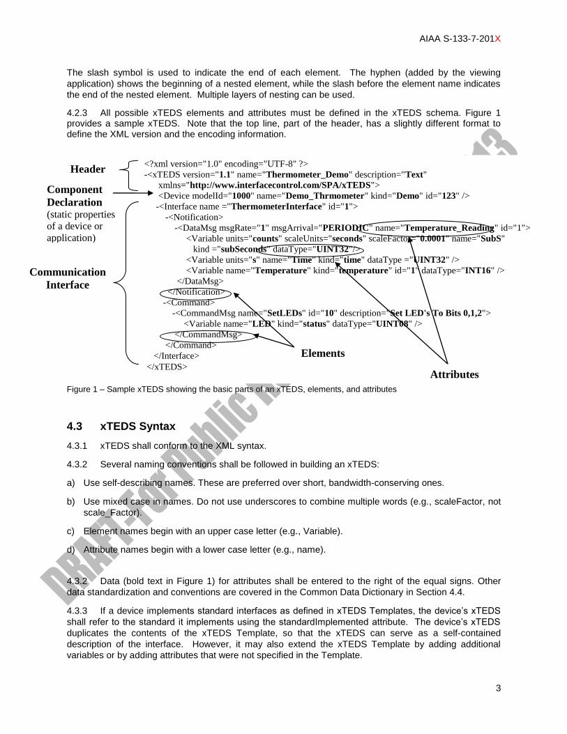
The slash symbol is used to indicate the end of each element. The hyphen (added by the viewing
application) shows the beginning of a nested element, while the slash before the element name indicates
the end of the nested element. Multiple layers of nesting can be used.
4.2.3 All possible xTEDS elements and attributes must be defined in the xTEDS schema. Figure 1 provides a sample xTEDS. Note that the top line, part of the header, has a slightly different format to define the XML version and the encoding information.
Figure 1 – Sample xTEDS showing the basic parts of an xTEDS, elements, and attributes
4.3 xTEDS Syntax
4.3.1 xTEDS shall conform to the XML syntax.
4.3.2 Several naming conventions shall be followed in building an xTEDS:
a) Use self-describing names. These are preferred over short, bandwidth-conserving ones.
b) Use mixed case in names. Do not use underscores to combine multiple words (e.g., scaleFactor, not
scale_Factor).
c) Element names begin with an upper case letter (e.g., Variable).
d) Attribute names begin with a lower case letter (e.g., name).
4.3.2 Data (bold text in Figure 1) for attributes shall be entered to the right of the equal signs. Other
data standardization and conventions are covered in the Common Data Dictionary in Section 4.4.
4.3.3 If a device implements standard interfaces as defined in xTEDS Templates, the device‟s xTEDS
shall refer to the standard it implements using the standardImplemented attribute. The device‟s xTEDS
duplicates the contents of the xTEDS Template, so that the xTEDS can serve as a self-contained
description of the interface. However, it may also extend the xTEDS Template by adding additional
variables or by adding attributes that were not specified in the Template.
<?xml version="1.0" encoding="UTF-8" ?>
-<xTEDS version="1.1" name="Thermometer_Demo" description="Text"
xmlns="http://www.interfacecontrol.com/SPA/xTEDS">
<Device modelId="1000" name="Demo_Thrmometer" kind="Demo" id="123" />
-<Interface name ="ThermometerInterface" id="1">
-<Notification>
-<DataMsg msgRate="1" msgArrival="PERIODIC" name="Temperature_Reading" id="1">
<Variable units="counts" scaleUnits="seconds" scaleFactor="0.0001" name="SubS"
kind ="subSeconds" dataType="UINT32"/>
<Variable units="s" name="Time" kind="time" dataType ="UINT32" />
<Variable name="Temperature" kind="temperature" id="1" dataType="INT16" />
</DataMsg>
</Notification>
-<Command>
-<CommandMsg name="SetLEDs" id="10" description="Set LED's To Bits 0,1,2">
<Variable name="LED" kind="status" dataType="UINT08" />
</CommandMsg>
</Command>
</Interface>
</xTEDS>
Header
rr Component
Declaration (static properties
of a device or
application)
Communication
Interface
Elements
Attributes
AIAA S-133-7-201X
4
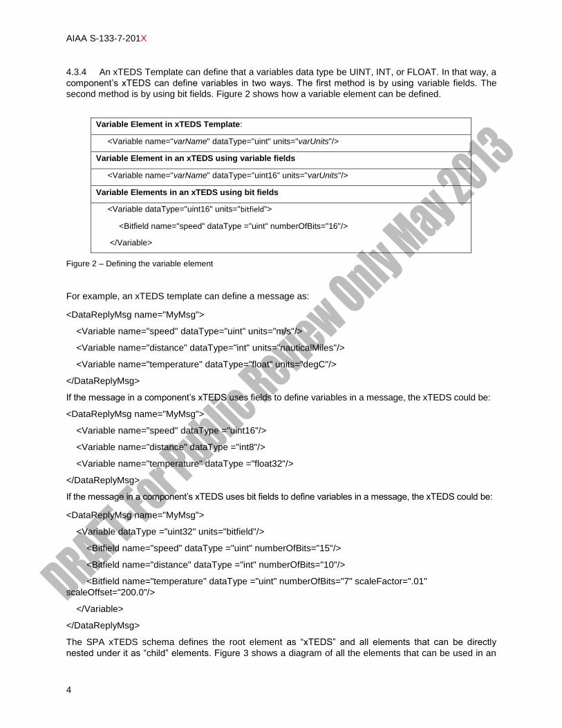
4.3.4 An xTEDS Template can define that a variables data type be UINT, INT, or FLOAT. In that way, a
component‟s xTEDS can define variables in two ways. The first method is by using variable fields. The
second method is by using bit fields. Figure 2 shows how a variable element can be defined.
Variable Element in xTEDS Template:
<Variable name="varName" dataType="uint" units="varUnits"/>
Variable Element in an xTEDS using variable fields
<Variable name="varName" dataType="uint16" units="varUnits"/>
Variable Elements in an xTEDS using bit fields
<Variable dataType="uint16" units="bitfield">
<Bitfield name="speed" dataType ="uint" numberOfBits="16"/>
</Variable>
Figure 2 – Defining the variable element
For example, an xTEDS template can define a message as:
<DataReplyMsg name="MyMsg">
<Variable name="speed" dataType="uint" units="m/s"/>
<Variable name="distance" dataType="int" units="nauticalMiles"/>
<Variable name="temperature" dataType="float" units="degC"/>
</DataReplyMsg>
If the message in a component‟s xTEDS uses fields to define variables in a message, the xTEDS could be:
<DataReplyMsg name="MyMsg">
<Variable name="speed" dataType ="uint16"/>
<Variable name="distance" dataType ="int8"/>
<Variable name="temperature" dataType ="float32"/>
</DataReplyMsg>
If the message in a component‟s xTEDS uses bit fields to define variables in a message, the xTEDS could be:
<DataReplyMsg name="MyMsg">
<Variable dataType ="uint32" units="bitfield"/>
<Bitfield name="speed" dataType ="uint" numberOfBits="15"/>
<Bitfield name="distance" dataType ="int" numberOfBits="10"/>
<Bitfield name="temperature" dataType ="uint" numberOfBits="7" scaleFactor=".01"
scaleOffset="200.0"/>
</Variable>
</DataReplyMsg>
The SPA xTEDS schema defines the root element as “xTEDS” and all elements that can be directly
nested under it as “child” elements. Figure 3 shows a diagram of all the elements that can be used in an
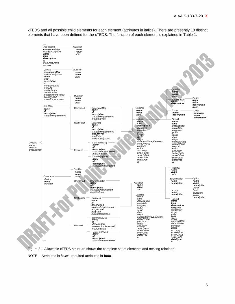
AIAA S-133-7-201X
5
xTEDS and all possible child elements for each element (attributes in italics). There are presently 18 distinct
elements that have been defined for the xTEDS. The function of each element is explained in Table 1.
Figure 3 – Allowable xTEDS structure shows the complete set of elements and nesting relations
NOTE Attributes in italics, required attributes in bold.
xTEDS
Application
Device
Interface
Qualifier
Qualifier
Command
Notification
Request
CommandMsg
DataMsg
DataReplyMsg
CommandMsg
Consumer
name value units
componentKey maxSubscriptions name kind description id manufacturerId version
componentKey maxSubscriptions name kind description id manufacturerId modelId versionLetter serialNumber measurementRange directionXYZ powerRequirements
name value units
Qualifier
name id description standardImplemented
name value units
name id description standardImplemented maxCmdRate
Curve
Bitfield Variable name kind description rangeMin rangeMax yLow yHigh rLow rHigh numberOfArrayElements defaultValue precision units accuracy scaleFactor scaleOffset scaleUnits dataType id
Qualifier name value units
Enumeration
name description exponent
value description
Coef
name kind description rangeMin rangeMax yLow yHigh rLow rHigh numberOfBits defaultValue precision units accuracy scaleFactor scaleOffset scaleUnits dataType id
Qualifier name value units
name id description standardImplemented msgArrival msgRate maxSubscriptions
name id description standardImplemented maxCmdRate
name id description standardImplemented
device name duration
Command
Notification
Request
CommandMsg
DataMsg
DataReplyMsg
CommandMsg
name id description standardImplemented maxCmdRate Curve
Bitfield Variable
name kind description rangeMin rangeMax yLow yHigh rLow rHigh numberOfArrayElements defaultValue precision units accuracy scaleFactor scaleOffset scaleUnits dataType id
Qualifier name value units
Enumeration
name description exponent
value description
Coef
Qualifier name value units
name id description standardImplemented msgArrival msgRate maxSubscriptions
name id description standardImplemented maxCmdRate name id description standardImplemented
name value units
Qualifier
name version description
name description
name value description alarm
Option
name kind description rangeMin rangeMax yLow yHigh rLow rHigh numberOfBits defaultValue precision units accuracy scaleFactor scaleOffset scaleUnits dataType id
name value description alarm
Option name description
AIAA S-133-7-201X
6
It is possible for a SPA component to have more than one interface. An interface is defined as a grouping
of messages by logical convenience, such as messages related to power or messages related to safety.
The groupings are determined by the xTEDS developer, but each interface must be complete and
uniquely defined in accordance with the XML and xTEDS schemas (i.e., messages in one interface
cannot reference variables defined in another interface). The same variable can be used in two different
interfaces, but it must be completely defined in each interface. Because the variable is defined by the
complete path name, similarly named variables with a different path can be defined differently.
Each element has one or more attributes that describe or define the element. A complete list of the
allowable attributes for each element is also provided in Table 1. The xTEDS schema provides detailed
descriptions for all the allowable elements and attributes.
Table 1 – Complete set of elements allowed in an xTEDS
Element Function Required Attributes Optional Attributes
xTEDS The root element, it defines the static properties and messages interfaces for SPA components
xmlns (xTEDS namespace) xmlns:xsi (XML namespace) xsi:schemaLocation name description
version
Application Defines the static properties of a SPA software application
componentKey name kind description
version manufacturerId id maxSubscriptions
Device Defines the static properties of a SPA hardware device
componentKey name kind description
manufacturerId id modelId versionLetter serialNumber powerRequirements measurementRange directionXYZ maxSubscriptions
Interface Defines the set of messages and variables implemented by the SPA component
name id description
standardImplemented
Consumer Defines the set of messages and variables consumed by SPA component
name device duration
Qualifier Provides additional information about the component. It can be used to query for components.
name value
units
AIAA S-133-7-201X
7
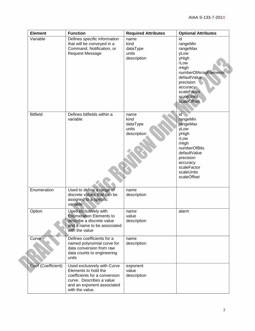
Element Function Required Attributes Optional Attributes
Variable Defines specific information that will be conveyed in a Command, Notification, or Request Message
name kind dataType units description
id rangeMin rangeMax yLow yHigh rLow rHigh numberOfArrayElements defaultValue precision accuracy scaleFactor scaleUnits scaleOffset
Bitfield Defines bitfields within a variable
name kind dataType units description
id rangeMin rangeMax yLow yHigh rLow rHigh numberOfBits defaultValue precision accuracy scaleFactor scaleUnits scaleOffset
Enumeration Used to define a range of discrete values that can be assigned to a specific variable
name description
Option Used exclusively with Enumeration Elements to describe a discrete value and a name to be associated with the value
name value description
alarm
Curve Defines coefficients for a named polynomial curve for data conversion from raw data counts to engineering units
name description
Coef (Coefficient) Used exclusively with Curve Elements to hold the coefficients for a conversion curve. Describes a value and an exponent associated with the value.
exponent value description
AIAA S-133-7-201X
8
Element Function Required Attributes Optional Attributes
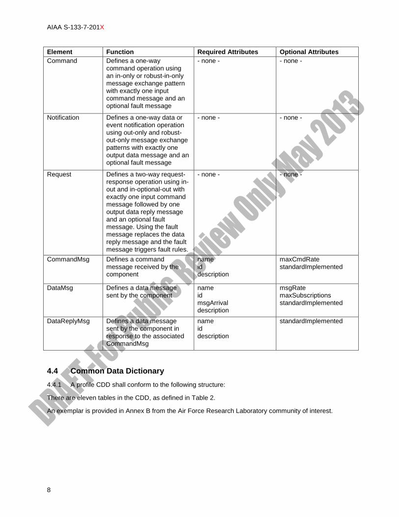
Command Defines a one-way command operation using an in-only or robust-in-only message exchange pattern with exactly one input command message and an optional fault message
- none - - none -
Notification Defines a one-way data or event notification operation using out-only and robust-out-only message exchange patterns with exactly one output data message and an optional fault message
- none - - none -
Request Defines a two-way request-response operation using in-out and in-optional-out with exactly one input command message followed by one output data reply message and an optional fault message. Using the fault message replaces the data reply message and the fault message triggers fault rules.
- none - - none -
CommandMsg Defines a command message received by the component
name id description
maxCmdRate standardImplemented
DataMsg Defines a data message sent by the component
name id msgArrival description
msgRate maxSubscriptions standardImplemented
DataReplyMsg Defines a data message sent by the component in response to the associated CommandMsg
name id description
standardImplemented
4.4 Common Data Dictionary
4.4.1 A profile CDD shall conform to the following structure:
There are eleven tables in the CDD, as defined in Table 2.
An exemplar is provided in Annex B from the Air Force Research Laboratory community of interest.
AIAA S-133-7-201X
9
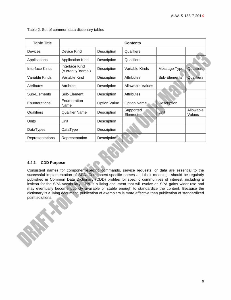
Table 2. Set of common data dictionary tables
Table Title Contents
Devices Device Kind Description Qualifiers
Applications Application Kind Description Qualifiers
Interface Kinds Interface Kind
(currently „name‟) Description Variable Kinds Message Type Qualifiers
Variable Kinds Variable Kind Description Attributes Sub-Elements Qualifiers
Attributes Attribute Description Allowable Values
Sub-Elements Sub-Element Description Attributes
Enumerations Enumeration
Name Option Value Option Name Description
Qualifiers Qualifier Name Description Supported
Element Unit
Allowable
Values
Units Unit Description
DataTypes DataType Description
Representations Representation Description
4.4.2. CDD Purpose
Consistent names for component-specific commands, service requests, or data are essential to the
successful implementation of SPA. Component-specific names and their meanings should be regularly
published in Common Data Dictionary (CDD) profiles for specific communities of interest, including a
lexicon for the SPA vocabulary. This is a living document that will evolve as SPA gains wider use and
may eventually become publicly available or stable enough to standardize the content. Because the
dictionary is a living document, publication of exemplars is more effective than publication of standardized
point solutions.
AIAA S-133-7-201X
10
Annex A Common Data Dictionary and xTEDS Extensions
A.1 CDD Purpose
Consistent names for component-specific commands, service requests, or data are essential to the
successful implementation of SPA. Component-specific names and their meanings should be regularly
published in Common Data Dictionary (CDD) profiles for specific communities of interest, including a
lexicon for the SPA vocabulary. This is a living document that will evolve as SPA gains wider use and
may eventually become publicly available or stable enough to standardize the content.
A.2 Updating the CDD
A web-based CDD management tool has been developed to support unification of the CDD without
compromising the fluidity inherent in SPA development. The tool provides a filter-able, sort-able list of
CDD entries. Entries can be approved by users identified as having a certain role (typical users can insert
/propose entries). Non-approved entries are clearly marked, and unapproved entries can be deselected
as another filter setting. Entries are organized as a file-folder taxonomy. In the CDD tool, any
(authenticated) user can propose CDD entries. They are reflected immediately in the CDD. They can be
public, private, or group shareable, and groups can also be defined by users (groups work well for
individual projects). Non-approved CDD entries that are non-private are viewable in the same display
area as approved CDD entries (when non-filtered).
The CDD tools support users having several defined roles: (1) approver, (2) reviewer, (3) user (and
omnipotent administrators):
a) Approvers can uniquely approve CDD entries, and deprecate, coalesce, or delete entries.
"Coalesce" is an operation in which a user can propose distillation/combination of two CDD
entries into one.
b) Reviewers can vote to approve, disapprove, or approve with comments.
c) Users can propose CDD entries, or coalesce/delete their own CDD entries.
Export/report options will eventually be supported. These tools support easy access and extension of the
CDD while providing a methodology for regulation through tagging mechanisms that can permit the
identification of approved, pending, as well as experimental extensions of the CDD. The goal is to
provide both legitimization of a mediated CDD while permitting implementers the flexibility to adhere to (or
if need be ignore) the conventions of such a CDD.
A.3 Validating XML Parser
xTEDS are validated against the latest xTEDS schema version using an XML Parser and Validator tool.
The W3C XML Schema was designed with the intent that determination of a document's validity would
produce a collection of information adhering to specific data types. It can be used with validation software
in order to ascertain whether a particular XML document is of that type, and to produce a Post Schema
Validation Infoset (PSVI). In the PSVI for an xTEDS, each element, attribute, and in general, any node of
the xTEDS XML document is assigned the data type from the xTEDS schema.
A parser used to validate the SPA xTEDS can actually test the xTEDS against the CDD to ensure only
approved terms are used.
AIAA S-133-7-201X
11
Annex B Exemplar SPA CDD
Two functions are critical in defining an ontology: Naming conventions and relationships between the
names. The naming conventions have been selected to cover the complete domain of data elements and
characteristics to be addressed by the SPA ontology. A mechanism for expressing the terms relationally,
a taxonomy, has also been defined so that the naming is unambiguous and terms cannot be mistakenly
used out of context. Specifically, the taxonomy subdivides the problem space into increasingly specialized
classes, relationally assigning logical names to precisely defined relational paths within the taxonomy.
The SPA Ontology is organized into a set of relational taxonomies to assign names to data and define
properties.
B.1 Ontology Naming Conventions
Several naming conventions are identified in 4.3. xTEDS Syntax, which shall be followed in building and
using a taxonomy:
a) Self-describing names are preferred over short, bandwidth-conserving ones. (4.3.2.)
b) Mixed case shall be used in names containing multiple words. Underscores are not used to
combine multiple words (e.g. scaleFactor, not scale_Factor). (4.3.2.)
c) Names taken from the DataPoint Taxonomy shall include the full path of the taxonomy, separated
by periods (e.g. DataPoint.Resource.Sensor.GPS.Time). The name in the final leaf of this
taxonomy is not always unique, so the full path name must be used. (4.3.4.)
d) All other names or properties taken from all other taxonomies shall include only the text in the
final leaf of the taxonomy (e.g., DumpMomentum, taken from the ComponentName Taxonomy).
The text in the final leaves of each of these taxonomies is always unique and therefore the full
path name is not required to ensure a unique name. (4.3.4.)
B.2 Taxonomies
There are four taxonomies, shown in Table B.1, needed to define the relationship between the spacecraft
component data and the properties that further define the data.
Table B.1. Complete set of taxonomies in the SPA Ontology
Taxonomy Number Taxonomy Name Associated xTEDS Attribute
1 StandardImplemented standardImplemented
2 Kind kind
3 Units units
4 Enumeration enumeration
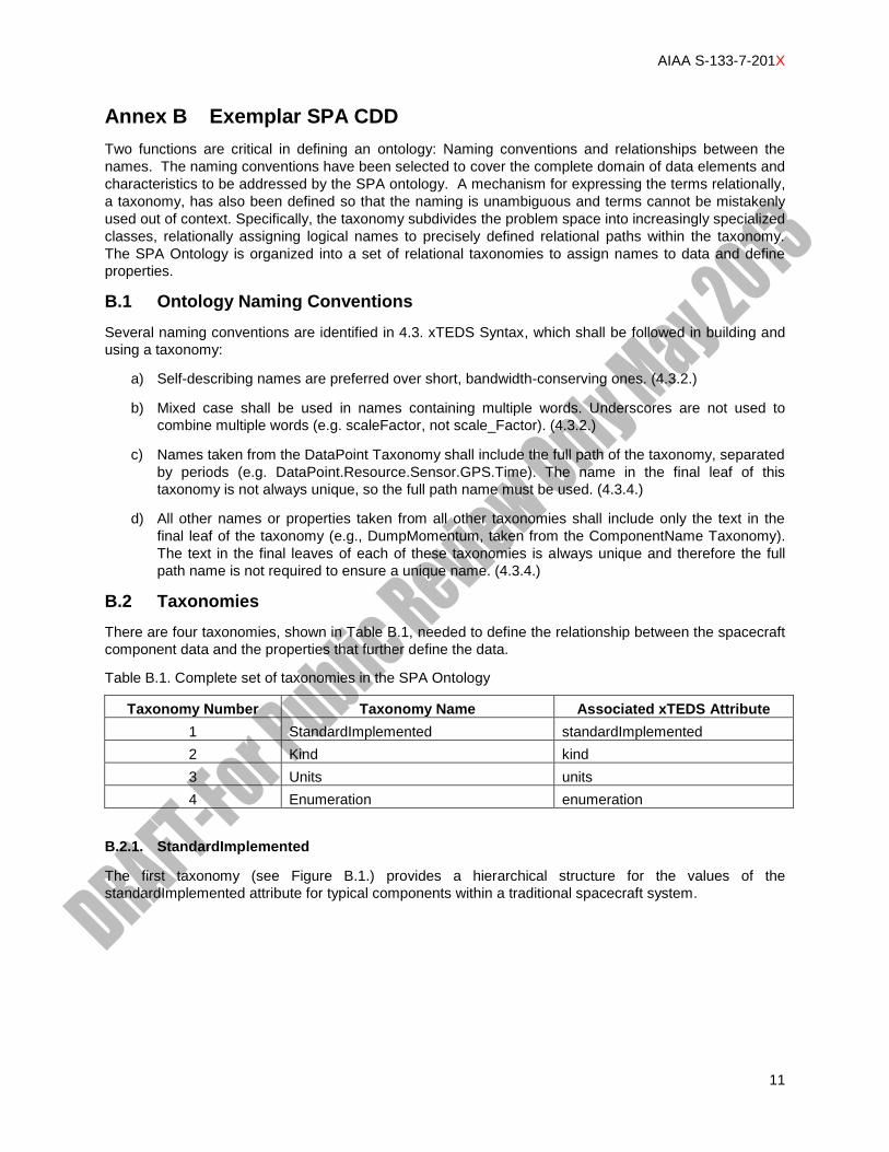
B.2.1. StandardImplemented
The first taxonomy (see Figure B.1.) provides a hierarchical structure for the values of the
standardImplemented attribute for typical components within a traditional spacecraft system.
AIAA S-133-7-201X
12
Figure B.1 – The StandardImplemented taxonomy
Stan
dar
dIm
ple
men
ted
Device
Temperature
SunSensor
StarCamera
StarTracker
SGLS
Radio
CDL
PowerProvider
PowerReset
Magnetometer
ReactionWheel
GPS
IMU
IRU
ActivityAgent
DumpMomentum
Slew
Tracking
ChargeBatteries
Imaging
ActivityScheduler
Subsystem Controller
ADCS
C&CH
Power
Thermal
Structural
Propulsion
Payload
Service
TimeProducer
TimeConsumer
SunAvailability
EnvironmentalModels
GPSAlmanacUpdates
StarCatalogUpdates
Utility
OrbitPropagator
AttitubePropagator
CoordinateTransforms
VectorAndMatrixMath
AIAA S-133-7-201X
13
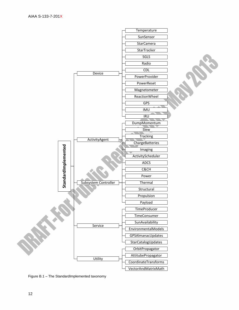
B.2.2. Kind
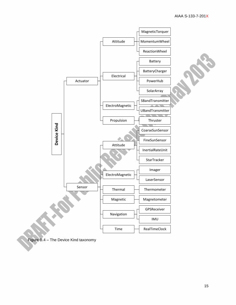
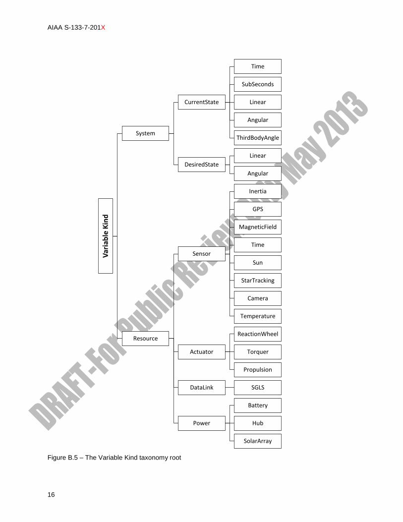
The Kind xTEDS attribute exists on the Application, Device, Variable, and Bitfield xTEDS elements. This
causes the Kind taxonomy to be the most complex taxonomy and require breakdown into multiple figures,
one per element. When completing the Kind attribute the element name is not required. For example,
in the Device element the kind would be kind=‟Sensor.Thermal.Thermometer‟, and not
kind=‟Device.Sensor.Thermal.Thermometer‟ since the Device is already implied by the Device element.
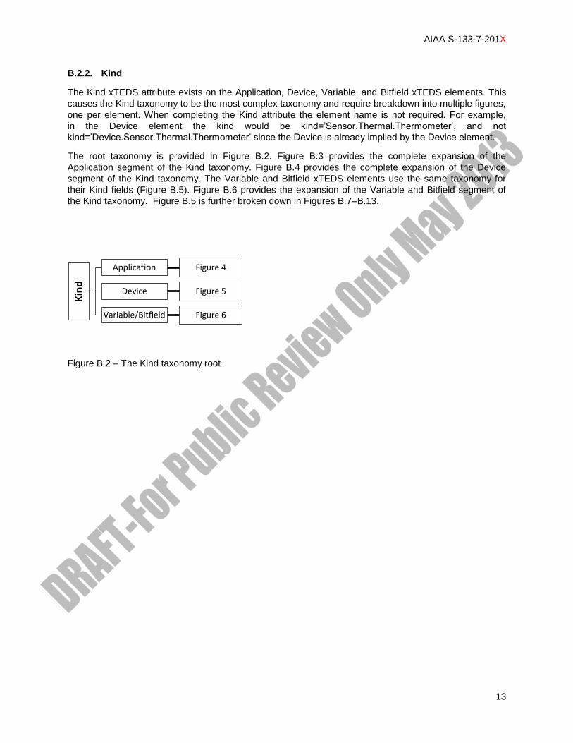
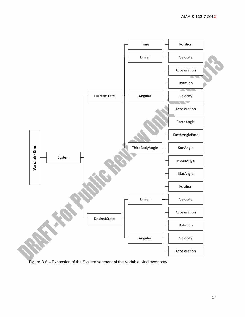
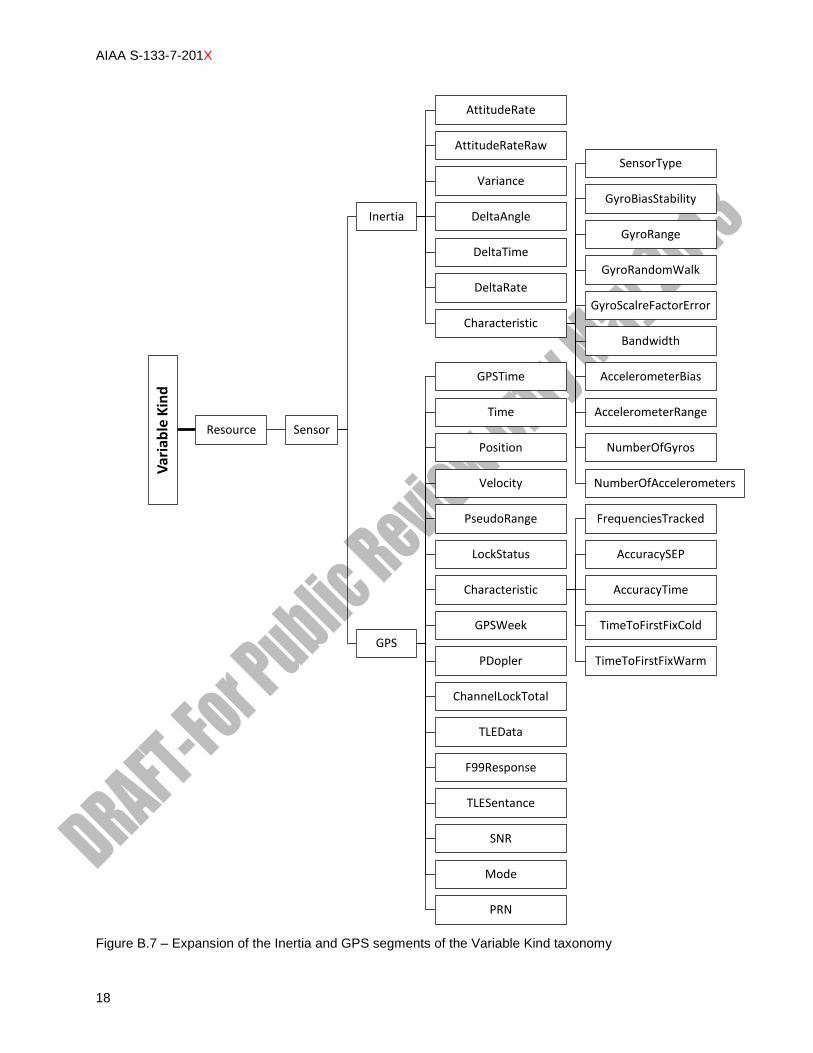
The root taxonomy is provided in Figure B.2. Figure B.3 provides the complete expansion of the
Application segment of the Kind taxonomy. Figure B.4 provides the complete expansion of the Device
segment of the Kind taxonomy. The Variable and Bitfield xTEDS elements use the same taxonomy for
their Kind fields (Figure B.5). Figure B.6 provides the expansion of the Variable and Bitfield segment of
the Kind taxonomy. Figure B.5 is further broken down in Figures B.7–B.13.
Figure B.2 – The Kind taxonomy root
Kin
d
Application Figure 4
Device Figure 5
Variable/Bitfield Figure 6
AIAA S-133-7-201X
14
Figure B.3 – The Application Kind taxonomy
Ap
plic
atio
n K
ind
ActivityAgent
Attitude
DumpMomentum
SlewAgent
TrackingAgent
Electrical ChargeBatteries
ElectroMagnetic ImagingAgent
Planning ActivityScheduler
ModeAgent
LaunchAndEarlyOps Separation
Operations
SunPoint
MissionOperations
SafeHold
GroundContact
EndOfLife Retire
Process
SunSensorSolution
Attitude
Control
Determination
Propogation
Electrical EPS Controller
Gravity EarthGravityField
Magnetic EarthMagneticField
Navigation
Control
Determination
Propogation
NavigationError
AIAA S-133-7-201X
15
Figure B.4 – The Device Kind taxonomy
Dev
ice
Kin
d
Actuator
Attitude
MagneticTorquer
MomentumWheel
ReactionWheel
Electrical
Battery
BatteryCharger
PowerHub
SolarArray
ElectroMagnetic
SBandTransmitter
UBandTransmitter
Propulsion Thruster
Sensor
Attitude
CoarseSunSensor
FineSunSensor
InertialRateUnit
StarTracker
ElectroMagnetic
Imager
LaserSensor
Thermal Thermometer
Magnetic Magnetometer
Navigation
GPSReceiver
IMU
Time RealTimeClock
AIAA S-133-7-201X
16
Figure B.5 – The Variable Kind taxonomy root
Var
iab
le K
ind
System
CurrentState
Time
SubSeconds
Linear
Angular
ThirdBodyAngle
DesiredState
Linear
Angular
Resource
Sensor
Inertia
GPS
MagneticField
Time
Sun
StarTracking
Camera
Temperature
Actuator
ReactionWheel
Torquer
Propulsion
DataLink SGLS
Power
Battery
Hub
SolarArray
AIAA S-133-7-201X
17
Figure B.6 – Expansion of the System segment of the Variable Kind taxonomy
Var
iab
le K
ind
System
CurrentState
Time
Linear
Position
Velocity
Acceleration
Angular
Rotation
Velocity
Acceleration
ThirdBodyAngle
EarthAngle
EarthAngleRate
SunAngle
MoonAngle
StarAngle
DesiredState
Linear
Position
Velocity
Acceleration
Angular
Rotation
Velocity
Acceleration
AIAA S-133-7-201X
18
Figure B.7 – Expansion of the Inertia and GPS segments of the Variable Kind taxonomy
Var
iab
le K
ind
Resource Sensor
Inertia
AttitudeRate
AttitudeRateRaw
Variance
DeltaAngle
DeltaTime
DeltaRate
Characteristic
SensorType
GyroBiasStability
GyroRange
GyroRandomWalk
GyroScalreFactorError
Bandwidth
AccelerometerBias
AccelerometerRange
NumberOfGyros
NumberOfAccelerometers
GPS
GPSTime
Time
Position
Velocity
PseudoRange
LockStatus
Characteristic
FrequenciesTracked
AccuracySEP
AccuracyTime
TimeToFirstFixCold
TimeToFirstFixWarm
GPSWeek
PDopler
ChannelLockTotal
TLEData
F99Response
TLESentance
SNR
Mode
PRN
AIAA S-133-7-201X
19
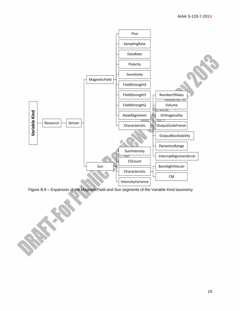
Figure B.8 – Expansion of the MagneticField and Sun segments of the Variable Kind taxonomy
Var
iab
le K
ind
Resource Sensor
MagneticField
Flux
SamplingRate
DataRate
Polarity
Sensitivity
FieldStrengthX
FieldStrengthY
FieldStrengthZ
AxialAlignment
Characteristic
NumberOfAxes
Volume
Orthogonality
OutputScaleFactor
OutputBiasStability
DynamicsRange
InternalAlignmentError
Sun
SunIntensity
CSCount
Characteristic
BoreSightVecotr
CM
IntensityVariance
AIAA S-133-7-201X
20
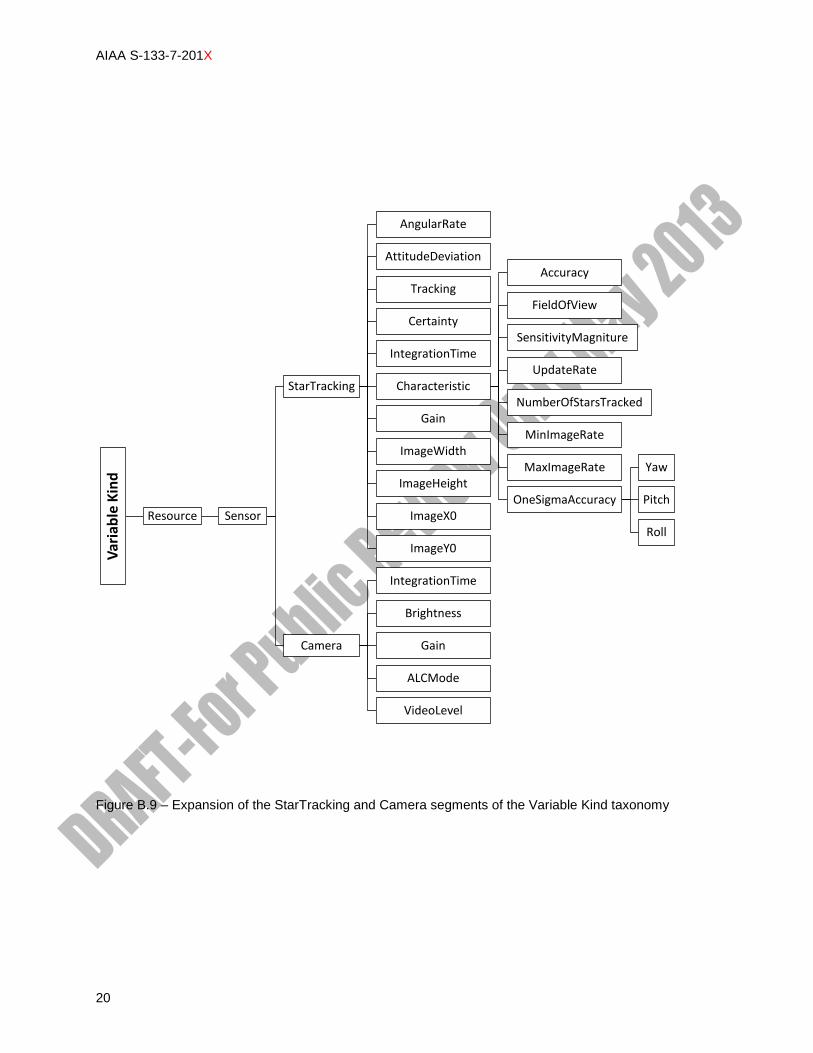
Figure B.9 – Expansion of the StarTracking and Camera segments of the Variable Kind taxonomy
Var
iab
le K
ind
Resource Sensor
StarTracking
AngularRate
AttitudeDeviation
Tracking
Certainty
IntegrationTime
Characteristic
Accuracy
FieldOfView
SensitivityMagniture
UpdateRate
NumberOfStarsTracked
MinImageRate
MaxImageRate
OneSigmaAccuracy
Yaw
Pitch
Roll
Gain
ImageWidth
ImageHeight
ImageX0
ImageY0
Camera
IntegrationTime
Brightness
Gain
ALCMode
VideoLevel
AIAA S-133-7-201X
21
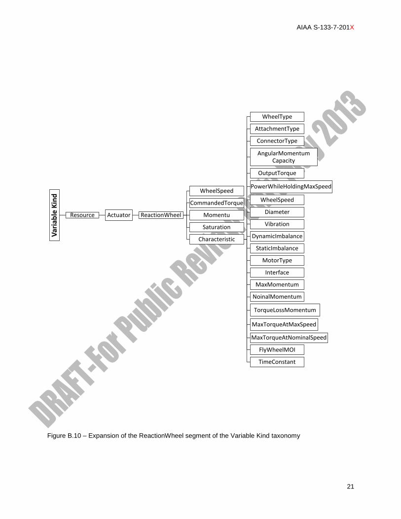
Figure B.10 – Expansion of the ReactionWheel segment of the Variable Kind taxonomy
Var
iab
le K
ind
Resource Actuator ReactionWheel
WheelSpeed
CommandedTorque
Momentu
Saturation
Characteristic
WheelType
AttachmentType
ConnectorType
AngularMomentum Capacity
OutputTorque
PowerWhileHoldingMaxSpeed
WheelSpeed
Diameter
Vibration
DynamicImbalance
StaticImbalance
MotorType
Interface
MaxMomentum
NoinalMomentum
TorqueLossMomentum
MaxTorqueAtMaxSpeed
MaxTorqueAtNominalSpeed
FlyWheelMOI
TimeConstant
AIAA S-133-7-201X
22
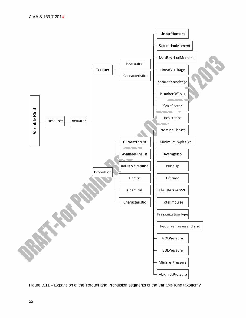
Figure B.11 – Expansion of the Torquer and Propulsion segments of the Variable Kind taxonomy
Var
iab
le K
ind
Resource Actuator
Torquer
IsActuated
Characteristic
LinearMoment
SaturationMoment
MaxResidualMoment
LinearVoldtage
SaturationVoltage
NumberOfCoils
ScaleFactor
Resistance
Propulsion
CurrentThrust
AvailableThrust
AvailableImpulse
Electric
Chemical
Characteristic
NominalThrust
MinimumImplseBit
AverageIsp
PluseIsp
Lifetime
ThrustersPerPPU
TotalImpulse
PressurizationType
RequiresPressurantTank
BOLPressure
EOLPressure
MinInletPressure
MaxInletPressure
AIAA S-133-7-201X
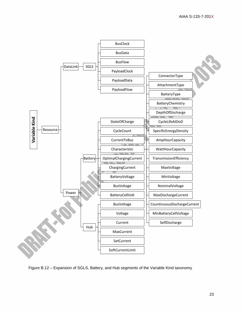
23
Figure B.12 – Expansion of SGLS, Battery, and Hub segments of the Variable Kind taxonomy
Var
iab
le K
ind
Resource
DataLink SGLS
BusClock
BusData
BusFlow
PayloadClock
PayloadData
PayloadFlow
Power
Battery
StateOfCharge
CycleCount
CurrentToBus
Characteristic
ConnectorType
AttachmentType
BatteryType
BatteryChemistry
DepthOfDischarge
CycleLifeAtDoD
SpecificEnergyDensity
AmpHourCapacity
WattHourCapacity
TransmissionEfficiency
MaxVoltage
MinVoltage
NominalVoltage
MaxDischargeCurrent
CountinuousDischargeCurrent
MinBatteryCellVoltage
SelfDischarge
OptimalChargingCurrent
ChargingCurrent
BatteryVoltage
BusVoltage
BatteryCellVolt
Hub
BusVoltage
Voltage
Current
MaxCurrent
SetCurrent
SoftCurrentLimit
AIAA S-133-7-201X
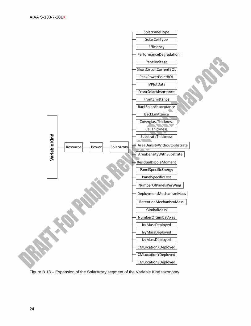
24
Figure B.13 – Expansion of the SolarArray segment of the Variable Kind taxonomy
Var
iab
le K
ind
Resource Power SolarArray
SolarPanelType
SolarCellType
Efficiency
PerformanceDegradation
PanelVoltage
ShortCircuitCurrentBOL
PeakPowerPointBOL
IVPlotData
FrontSolarAbsortance
FrontEmittance
BackSolarAbsorptance
BackEmittance
CoverglassThickness
CellThickness
SubstrateThickness
AreaDensityWithoutSubstrate
AreaDensityWithSubstrate
ResidualDipoleMoment
PanelSpecificEnergy
PanelSpecificCost
NumberOfPanelsPerWing
DeploymentMechanismMass
RetentionMechanismMass
GimbalMass
NumberOfGimbalAxes
IxxMassDeployed
IyyMassDeployed
IzzMassDeployed
CMLocationXDeployed
CMLocationYDeployed
CMLocationZDeployed
AIAA S-133-7-201X
25
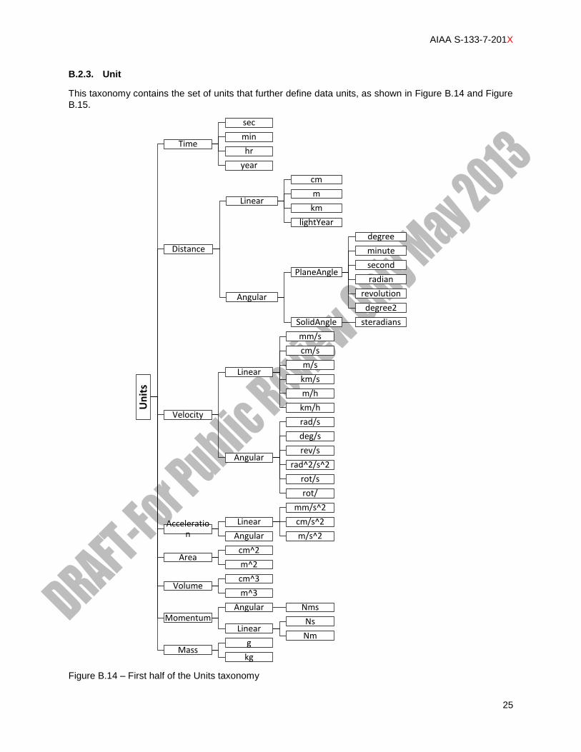
B.2.3. Unit
This taxonomy contains the set of units that further define data units, as shown in Figure B.14 and Figure
B.15.
Figure B.14 – First half of the Units taxonomy
Un
its
Time
sec
min
hr
year
Distance
Linear
cm
m
km
lightYear
Angular
PlaneAngle
degree
minute
second
radian
revolution
degree2
SolidAngle steradians
Velocity
Linear
mm/s
cm/s
m/s
km/s
m/h
km/h
Angular
rad/s
deg/s
rev/s
rad^2/s^2
rot/s
rot/
Acceleration
Linear
mm/s^2
cm/s^2
m/s^2 Angular
Area cm^2
m^2
Volume cm^3
m^3
Momentum Angular Nms
Linear Ns
Nm
Mass g
kg
AIAA S-133-7-201X
26
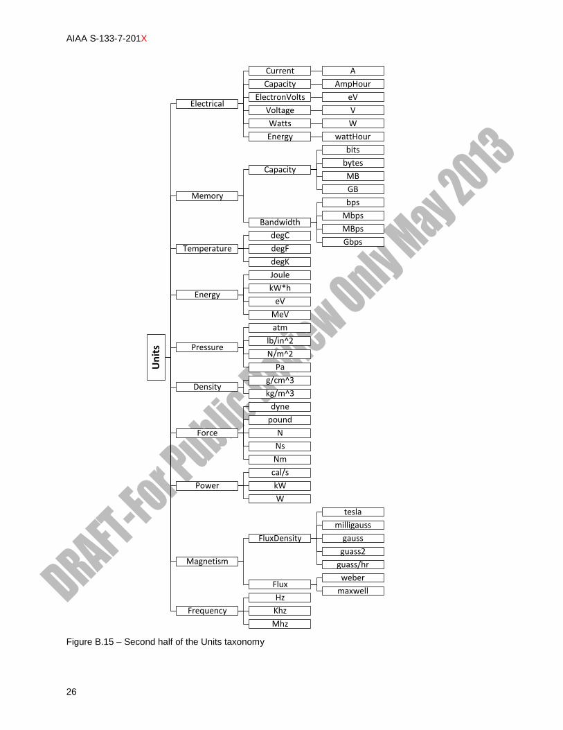
Figure B.15 – Second half of the Units taxonomy
Un
its
Electrical
Current A
Capacity AmpHour
ElectronVolts eV
Voltage V
Watts W
Energy wattHour
Memory
Capacity
bits
bytes
MB
GB
Bandwidth
bps
Mbps
MBps
Gbps Temperature
degC
degF
degK
Energy
Joule
kW*h
eV
MeV
Pressure
atm
lb/in^2
N/m^2
Pa
Density g/cm^3
kg/m^3
Force
dyne
pound
N
Ns
Nm
Power
cal/s
kW
W
Magnetism
FluxDensity
tesla
milligauss
gauss
guass2
guass/hr
Flux weber
maxwell
Frequency
Hz
Khz
Mhz
AIAA S-133-7-201X
27
B.2.4. Enumeration
Table B.2. and Table B.3. provide the details for dual and multiple-option enumerations.
Several conventions will be followed in defining a standard enumeration:
a) Dual-Option Enumerations shall always have „No‟ (0) and „Yes‟ (1) as the defined options. The
name of the enumeration will be selected so that when stated as a question, the standard
answers apply, for example, Deployed, when stated as a question, “Deployed?”, the answer is
„No‟ (not deployed) or „Yes‟ (deployed).
b) Multiple-Option Enumerations shall always begin with number 1 on the first option and number all
other options consecutively (2, 3, 4, …). The number 0 should not be used.
Table B.2. The set of dual-option enumerations
Name Option
Value
Option
Name
ActiveState (StateActive)
0 1
No Yes
Armed 0 1
No (Safe) Yes
Available 0 1
No Yes
ByPassed 0 1
No Yes
GoodCondition 0 1
No (Bad) Yes
DataStale (StaleData)
0 1
No Yes
Deployed 0 1
No (Stow) Yes
On-Orbit 0 1
No (Ground) Yes
Enabled 0 1
No Yes
AlwaysRunning 0 1
No (Normal) Yes
FlagSet 0 1
No Yes
LevelHigh 0 1
No (Low) Yes
LogicState 0 1
No Yes
PolaritySouth 0 1
No (North) Yes
PowerOn 0 1
No Yes
Response 0 1
No Yes
Subscribed 0 1
No Yes
AIAA S-133-7-201X
28
Table B.3. The set of multiple-option enumerations
Name Option Value Option Name
ActivityStatus 1
2
3
4
5
6
7
8
9
Schedule Failure
Waiting
Enabled
Terminated
Executing
Completed with faults
Failure
Completed Successfully
Not Executed
EndPoint/PowerState 1
2
3
4
Off
On
Tripped
Not Working
TargetTrack/TrackStatus
1
2
3
Track / Lock
Break_Lock
Acquisition
DownlinkControllerStatusIF/
DownlinkControllerStatus
1
2
3
4
Not_Initialized
Initializing
Operating
Terminating
SessionRequest/
SessionMode
1
2
3
4
5
7
End
RX_Only
TX_On
BEEP
Originate
SPWPassThru
DeployerInterface/
DeployedState
1
2
3
Stowed
DeployedA
DeployedB
ResetReason 1
2
3
4
5
6
7
8
9
PowerCycle
Realtime clock
Flash
Comparator0
Watchdog
Missing Clock
External Reset Pin
Commanded Reset
Other

1
American Institute of Aeronautics and Astronautics
1801 Alexander Bell Drive, Suite 500
Reston, VA 20191-4344
www.aiaa.org
ISBN 978-1-62410-235-6


![SUPERPOWER RESPONSIBILITY FOR STATE RECOGNITION: … · CHHABRA_JCI(2)-1.DOCX (DO NOT DELETE) 4/23/13 12:16 PM 201x] SUPERPOWER RESPONSIBILITY FOR STATE RECOGNITION 133 jure independence](https://img.pdfslide.us/doc/110x75/613f3b31a7a58608c268ca4f/superpower-responsibility-for-state-recognition-chhabrajci2-1docx-do-not-delete.jpg)


![, Allen, C., & Rendall, T. (2019). Efficient Aero-Structural Wing AIAA Scitech … · In AIAA Scitech 2019 Forum [AIAA 2019-1701] (AIAA Scitech 2019 Forum). American Institute of](https://img.pdfslide.us/doc/110x75/6089b44b26d0b4646a6cbe59/-allen-c-rendall-t-2019-efficient-aero-structural-wing-aiaa-scitech.jpg)