Embed Size (px)
Citation preview

For permission to copy or to republish, contact the American Institute of Aeronautics and Astronautics,1801 Alexander Bell Drive, Suite 500, Reston, VA, 20191-4344.
AIAA 2002-3917
Engine Cycle and Exhaust Configurations for Quiet Supersonic Propulsion
D. PapamoschouDept. of Mechanical & Aerospace EngineeringUniversity of California at IrvineIrvine, CA
38th AIAA/ASME/SAE/ASEE Joint Propulsion Conference & Exhibit
7-10 July 2002Indianapolis, Indiana
AIAA-2002-3917
ENGINE CYCLE AND EXHAUST CONFIGURATIONS FOR
QUIET SUPERSONIC PROPULSION
Dimitri Papamoschou �
University of California, Irvine, Irvine, California 92697-3975
This study explores the thermodynamics and acoustics of a �xed-cycle, bypass ratio 3 su-
personic engine with an innovative noise suppression scheme. The silencing method entails
installation of turning vanes in the bypass exhaust of a separate- ow turbofan engine. The
vanes produce locally-skewed mixing layers between the core and bypass ows and give a slight
downward tilt to the bypass plume relative to the core plume. The former e�ect reduces the
length of the core noise source region and the latter e�ect thickens the bypass stream on the
underside of the jet. This results in a reduction of the convective Mach number of instability
waves that produce intense downward sound radiation. Subscale experiments show a sub-
stantial noise bene�t. Relative to the mixed- ow exhaust, the coaxial separate- ow exhaust
with vanes reduces the peak overall sound pressure level by 8 dB and the e�ective perceived
noise level by 7 dB. The noise-equivalent speci�c thrust on takeo� is reduced from 490 m/s to
390 m/s. Compared to a current-generation low-bypass turbofan engine, the bypass ratio 3
engine is estimated to be 13-dB quieter with the mixed- ow exhaust and 20-dB quieter with
the aforementioned suppression scheme.
Nomenclature
D = diameter or drag
f = frequency
_m = mass ow rate
M = Mach number
U = velocity
r = distance from jet exit
t = time from lift o�
T = thrust
x = horizontal distance from brake release
y = altitude
� = geometric angle of attack
= climb angle
� = polar angle relative to jet centerline
� = azimuth angle relative to vertical plane
= polar observation angle of airplane
�Professor, Associate Fellow AIAA
Copyright c 2002 by D. Papamoschou. Published by the
American Institute of Aeronautics and Astronautics, Inc.
with permission.
�� Noise suppression via de ection of the bypass and/or
core streams is proprietary to the University of California.
U.S. Patent Pending.
Subscripts
com = compressor
eng = full-scale engine
exp = subscale experiment
fan = fan tip
LO = lift o�
p = primary (core) exhaust
s = secondary (bypass) exhaust
TOM = takeo� monitor
tot = total
1 = ight conditions
Abbreviations
BPR = Bypass Ratio
EPNL = E�ective Perceived Noise Level
FPR = Fan Pressure Ratio
PNL = Perceived Noise Level
PNLM = Maximum value of PNL
SPL = Sound Pressure Level
OASPL= Overall Sound Pressure Level
OPR = Overall Pressure Ratio
TIT = Turbine Inlet Temperature
TSFC = Thrust Speci�c Fuel Consumption
1

Introduction
Development of large-scale supersonic transporta-
tion has been a long-sought and elusive goal for the
aerospace industry. The eÆciency and environmen-
tal compliance of a viable supersonic airplane should
be on a par with those of advanced subsonic air-
craft. Environmental problems include emissions,
sonic boom, and takeo� noise. The latter has been
the subject of intense research and development for
over forty years, which has led to signi�cant progress
in our understanding and prediction of jet noise.
A large variety of noteworthy suppression schemes
were proposed and investigated. However, the prob-
lem today remains as challenging as it was forty
years ago [1].
At the heart of the issue are the con icting require-
ments for an engine that is both quiet on takeo�
and eÆcient at supersonic cruise. Quiet takeo� re-
quires low speci�c thrust (high mass ow rate). Ef-
�cient supersonic cruise entails high speci�c thrust
(low mass ow rate), primarily to minimize the
frontal area of the engine. In an e�ort to resolve
this con ict, past e�orts have investigated engines
with variable-geometry ejectors [2] as well as tur-
bofan engines with variable cycle (variable bypass
ratio). These concepts are notable and are still be-
ing pursued but, at present, entail complexity far
greater than that of today's commercial engines.
An ideal concept, of course, would be a �xed-cycle
engine that is quiet on takeo� and eÆcient at cruise.
While this idea was probably unfeasible several years
ago, advances in engine technology bring it closer to
reality today. A key parameter is the turbine inlet
temperature (TIT). As will be shown in the next
section, increasing TIT allows a supersonic engine
to operate at higher bypass ratio while maintaining
a reasonably small frontal area. Of course, the by-
pass ratio will never reach the values found in mod-
ern subsonic engines, which range from �ve to nine.
Reasonable values for supersonic engines are in the
ballpark of two to three; higher values would lead to
prohibitively large frontal areas.
This means that noise is still an issue as the su-
personic engine on takeo� will have higher speci�c
thrust than its subsonic counterparts. Can an an
aircraft powered by engines with bypass ratio three
become as quiet as one powered by engines with by-
pass ratio eight? The complete answer requires a
systems-level view that, at a minimum, considers the
following basic and interdependent elements: (a) en-
gine cycle; (b) exhaust con�guration; (c) perceived
noise (as opposed to absolute noise); and (d) air-
craft performance. It is conceivable that optimiza-
tion at the systems level, and implementation of non-
traditional exhaust concepts, will lead to a very quiet
airplane even though the engine has higher speci�c
thrust than its subsonic counterparts.
This study looks at the above four elements, with
emphasis on the e�ect of exhaust con�guration.
Given that the bypass ratio is moderate, it be-
comes crucial how one uses the bypass stream to
reduce noise. One arrangement is the mixed- ow
exhaust, currently used on all military engines, in
which the bypass and core streams mix before exit-
ing a common nozzle. The other option is the sep-
arate (unmixed)- ow turbofan, which is very com-
mon on subsonic transports. The unmixed design
allows shaping of the bypass exhaust so that the by-
pass stream \shields" noise emitted from the core
stream. Past work on a BPR=1.6 supersonic engine
[3] has demonstrated the substantial noise bene�t
of eccentric separate- ow nozzles. Most recently, al-
ternatives to the eccentric arrangement were devel-
oped that make the exhaust arrangement even sim-
pler and allow online control of noise suppression [4].
This paper extends the BPR=1.6 work to BPR=3.0
and assesses the impact of the new nozzle con�gu-
rations.
Engine Cycle
Advances in turbine technology will soon allow
steady-state (cruise) operation at turbine inlet tem-
peratures around 1800-1900ÆK. This means that
more power will be available to drive a fan with by-
pass ratio larger than those traditionally used in su-
personic turbofan engines (0.5 or less.) Large bypass
ratio is desired for quiet takeo� but increases the
frontal area of the engine, which is undesirable for
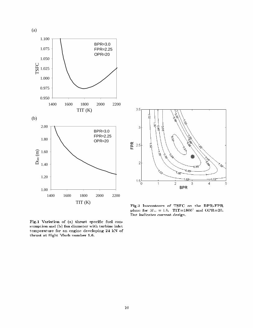
supersonic operation. However, at constant thrust,
bypass ratio, and fan pressure ratio, the fan diam-
eter decreases with increasing TIT. Figure 1 plots
the variation of fan diameter and thrust speci�c fuel
consumption versus TIT at Mach 1.6 cruise for an
engine with BPR=3.0 and FPR=2.2. The plots are
based an a cycle analysis described later in this sec-
tion. There is clearly a very signi�cant bene�t of
a reduced frontal area with increasing TIT. For the
conditions shown on the plot, the TSFC has a min-
imum around TIT=1800ÆK. So a cruise setting of
TIT=1800ÆK seems to be a reasonable design point.
Given a turbine inlet temperature in the neighbor-
2

Table 1: Engine Cycle Assumptions
Component EÆciency Speci�c heat ratio
Inlet (M1 < 1) 0.97 1.40
Inlet (M1 � 1) 0.85 1.40
Fan 0.85 1.40
Compressor 0.85 1.37
Combustor 1.00(1) 1.35
Turbine 0.90 1.33
Nozzle 0.97 calc.(2)
(1) With 5% total pressure loss
(2) From internal mixing calculation
Table 2: Engine Characteristics at Supersonic Cruise
(y = 16000 m, M1 = 1:6, W = 480 kN)
B03-MIX B30-SEP B30-MIX
OPR 20 20 20
TIT (K) 1600 1800 1800
_mcom (kg/s) 44 34 34
_mtot (kg/s) 57 89 89
T (kN) 24 24 24
BPR 0.3 3.0 3.0
FPR 4.5 2.25 2.25
D(2)
fan (m) 0.93 1.44 1.44
TSFC (kg/kgf-h) 0.980 0.975 0.974(2)
Mp 2.06 1.54 1.75
Up (m/s) 890 760 650
Ms - 1.96 -
Us (m/s) - 610 -
(1) M = 0:7 at fan face
(2) Does not account for mixer losses
Table 3: Engine Characteristics at Takeo�
(y = 0 m, M1 = 0:3, W = 540 kN)
B03-MIX B30-SEP B30-MIX
OPR 20 20 20
TIT (K) 1800 2000 2000
_mcom (kg/s) 120 94 94
_mtot (kg/s) 157 377 377
T (kN) 112 140 145
BPR 0.3 3.0 3.0
FPR 5.0 2.12 2.12
D(1)
fan(m) 0.93 1.44 1.44
TSFC (kg/kgf-h) 0.778 0.587 0.565(2)
Mp 1.55 1.19 1.14
Up (m/s) 770 700 490
Ms - 1.12 -
Us (m/s) - 390 -
(1) M = 0:5 at fan face
(2) Does not account for mixer losses
3

hood of 1800ÆK, it is important to know what are
the conditions that minimize fuel consumption. The
overall pressure ratio (OPR), which for a supersonic
engine should be in the range 15-25, has very slight
e�ect on TSFC. The e�ects of bypass ratio (BPR)
and fan pressure ratio (FPR) are shown in Figure 2,
which plots iso-contours of TSFC on the BPR-FPR
plane. The minimum TSFC occurs at BPR=2.2 and
FPR=2.5. What is optimal for cruise, however, may
not be the best choice for takeo�. A bypass ratio of
2.2 may be too small for quiet operation. In ad-
dition, fan pressure ratios above 2.4 will likely re-
quire a two-stage fan which complicates engine de-
sign. The selection here is an engine with BPR=3.0
and FPR=2.25. As seen in Fig. 2, this condition is
very close to the optimum point yet increases sig-
ni�cantly the chances for meeting noise regulations
and a�ords the simplicity of a single-stage fan.
This study investigates the thermodynamic perfor-
mance and noise emission from a \next generation"
BPR=3.0 supersonic engine with a variety of ex-
haust arrangements. The exhaust con�gurations can
be broken down into two broad classes, mixed- ow
and separate- ow. For the separate- ow exhaust,
nozzle arrangements will comprise coaxial, eccentric,
and coaxial with de ectors in the bypass stream. A
\current generation" supersonic turbofan engine is
included in the comparisons in order to assess the
improvements of the new concepts.
To size the engines, we consider a supersonic twin-
engine aircraft with maximum takeo� weight of 540
kN (120,000 lb.) and wing loading of 4450 N/m2
(100 lb/ft2). The assumed lift-to-drag ratio is 5 at
takeo� and 10 at supersonic cruise, values roughly
20% better than those of the Aerospatiale Concorde
[5]. Weight at cruise is 480 kN, based on an average
TSFC=0.6 kg/(kgf-hr) and a 20-min climb to cruise
altitude.
The comparison basis is that all engines have the
same cruise thrust at Mach 1.6 and altitude of 16000
m. On takeo�, the TIT is 200ÆK greater than the
cruise setting while the OPR and FPR values are
roughly the same as at cruise. The size, speci�c
fuel consumption, and exhaust conditions are de-
rived from thermodynamic analysis of a Brayton cy-
cle with component eÆciencies and speci�c heat ra-
tios listed in Table 1 (see Ref. [7] for more informa-
tion on the cycle analysis.) For all engines, 25-30%
of the compressor air is used for turbine cooling; 1%
of the compressor air is bled to systems outside the
engine; and 1.5% of the turbine work drives auxiliary
systems. Total pressure loss due to turbine cooling
is estimated at 7% times the mass fraction of cool-
ing air [6]. For the mixed- ow designs, the core and
fan streams mix at constant pressure, constant total
enthalpy, and Mach number 0.4 before expanding to
ambient pressure.
Tables 2 and 3 summarize engine characteristics and
thermodynamic performance at supersonic cruise
and takeo�, respectively. For convenience, we adopt
a notation that gives the bypass ratio and type of ex-
haust. B30-MIX, for example, describes the bypass
ratio 3.0, mixed- ow engine. Because of its small
bypass ratio, the \current generation" engine (B03-
MIX) operates at much larger fan pressure ratio
than the B30 variants. Increasing the bypass ratio
from 0.3 (\current generation") to 3.0 (\next gener-
ation") produces a modest decrease in fuel consump-
tion at supersonic cruise. There is hardly any di�er-
ence between the fuel consumption of the separate-
ow and mixed- ow B30 engines. In fact, the ac-
tual fuel consumption of B30-MIX may be slightly
higher because of losses caused by the mixer. The
velocity ratio of the separate- ow exhaust at cruise,
Us=Up = 0:80, is very close to the eÆciency of en-
ergy transfer between the core and bypass ows (the
product of turbine and fan eÆciencies, in this case
0.76). This indicates that B30-SEP operates near
optimal cruise conditions [9].
On takeo�, the B30 engines produce substantially
more thrust than does the low-bypass reference en-
gine. The thrust-to-weight ratio is 0.5 for the B30-
powered aircraft versus 0.4 for the reference case.
The resulting initial climb angle,
= arcsin
�T �D
W
�
is 19Æ for the B30-powered aircraft versus 12Æ for the
B03-powered aircraft and � 15Æ for modern twin-
engine subsonic aircraft. The steep climb angle gives
the B30-powered aircraft an inherent noise advan-
tage over the reference airplane.
Besides engine performance, important information
that comes from the cycle analysis includes the
exhaust velocities and Mach numbers on takeo�.
These conditions are duplicated in subscale tests to
assess the acoustics of each con�guration.
Exhaust Con�gurations
Past research on high-speed jets has shown the pow-
erful noise bene�t of reshaping a dual-stream nozzle
4

from coaxial to eccentric [10]. Downward-directed
Mach wave emission was reduced by the combination
of two factors: shortening of the primary potential
core (relative to the coaxial jet) and thickening of
the secondary ow in the downward direction [11].
This synergism resulted in a reduction of the convec-
tive Mach number of ow instabilities that produce
intense downward-radiated sound [4].
Very recent experiments have shown that the ef-
fect of the eccentric con�guration can be achieved
in a coaxial jet with de ectors placed in the bypass
stream. The de ectors are small aps, or vanes, that
induce a slight downward tilt in the direction of the
bypass stream. It is believed that this de ection
scheme achieves two goals simultaneously: (a) cre-
ation of skewed mixing layers in the vicinity of the
nozzle exit that enhance mixing and shorten the pri-
mary potential core; and (b) direction of most of the
bypass stream to the lower side of the jet so that it
shields the end of the potential core. For more de-
tails the reader is referred to Ref. [4].
Figure 3 shows exemplary illustrations of the
separate- ow con�gurations considered for the B30
engines: coaxial; eccentric; and coaxial with vanes
installed in the bypass stream. Figure 4 shows spark
schlieren images that tend to support the hypothe-
sis stated above about the e�ect of the vanes. The
clean coaxial jet spreads very slowly. Insertion of
vanes enhances mixing considerably and thickens the
bypass stream on the underside of the jet. The de-
ectors produce superior noise reduction compared
to the eccentricity method. Applied to an engine,
they could be actively de ected or deployed, con-
�ning any thrust losses to the takeo� and landing
segments only.
Facilities and Flow Conditions
Noise testing was conducted in UCI's Jet Aeroacous-
tics Facility [10]. Single- and dual-stream jets with
ow conditions matching those given by the cycle
analysis (Table 3) were produced. The jets were
composed of helium-air mixtures, which duplicate
very accurately the uid mechanics and acoustics of
hot jets [12]. Jet nozzles were fabricated from epoxy
resin using rapid-prototyping techniques. The noz-
zles of BO3-MIX and B30-MIX cases were designed
with the method of characteristics for Mach num-
bers 1.5 and 1.2, respectively. For the separate- ow
con�gurations, the primary nozzle was convergent,
terminating in a constant-area section, and had a
plug along its centerline. All primary nozzles had
the same exit inner diameter (14.8 mm), lip thick-
ness (0.7 mm), and external shape. The plug diam-
eter was 10.0 mm. One secondary (bypass) nozzle
formed a convergent duct in combination with the
primary nozzles and terminated in a diameter of 21.8
mm. The pipe that fed the primary nozzle was able
to ex, enabling coaxial or eccentric secondary ow
passages. For all nozzles, the radial coordinates of
the contraction (prior to any supersonic expansion)
were given by �fth-order polynomials. The contrac-
tion ratio was 4:1 for the core nozzles (8:1 with the
plug inserted) and 15:1 for the bypass nozzle. The
jet Reynolds number was on the order of 0.5�106.
Table 1 summarizes the ow conditions.
Figure 5 shows a picture of the B30 nozzle with de-
ectors attached. The outer wall of the core nozzle
extended past the exit of the bypass nozzle. Four
vanes, made of thin metal sheet, were attached on
the outer wall of the core nozzle immediately past
the exit of the bypass nozzle. With � = 0 indicat-
ing the downward vertical direction, the vanes were
placed at azimuth angles � = �80Æ and �110Æ. The
vane angle of attack was approximately 20Æ. The
size of each vane was 4 mm in chord by 1.7 mm in
width. The width was 40% smaller than the annu-
lus thickness of the bypass duct. The forces on the
vanes were calculated from basic aerodynamic rela-
tions [17]. Each vane was treated as a wing with
aspect ratio equal to twice the width divided by the
chord length. The two dimensional lift slope was as-
sumed to be 0.1/deg and the parasite drag coeÆcient
was assumed to be 0.01. Because of the small aspect
ratio, the three-dimensional lift slope is quite small
(around 0.04 /deg), allowing de ections up to about
25Æ without exceeding a lift coeÆcient of 1.0. It is
expected, therefore, that the vanes are not stalled
even at such high angle of attack.
Noise measurements were conducted inside an ane-
choic chamber using a one-eighth inch condenser mi-
crophone (Br�uel & Kj�r 4138) with frequency re-
sponse of 140 kHz. The microphone was mounted
on a pivot arm and traced a circular arc centered
at the jet exit with radius of 70-100 core diameters.
Earlier experiments have determined that this dis-
tance is well inside the acoustic far �eld [13]. Figure
6 depicts the overall setup and the range of polar
angles covered. The sound spectra were corrected
for the microphone frequency response, free �eld re-
sponse, and atmospheric absorption. Comparison at
equal thrust was done using geometric scaling [13].
5

Table 1: Flow Conditions
Test Con�guration Dp Up Mp Ds Us Ms F ��
xF ��
y
(mm) (m/s) (mm) (m/s)
B30-MIX Mixed ow 14.4 490 1.14 - - - 0.0% 0.0%
B30-COAX Coaxial (clean) 10.0� 700 1.19 21.8 390 1.12 0.0% 0.0%
B30-ECC Eccentric 10.0� 700 1.19 21.8 390 1.12 Unknown Unknown
B30-4V20e Coaxial with four 10.0� 700 1.19 21.8 390 1.12 1.7% 5.0%
vanes inclined 20Æ,
ext. to bypass duct
B03-MIX Mixed ow (ref.) 14.4 770 1.55 - - - 0.0% 0.0%� This is the e�ective (area-based) diameter of the primary nozzle. Actual dimensions are 14.4 mm ID with a 10-mm plug.��
Fx and Fy are estimates of the axial and transverse forces, respectively, caused by the nozzle modi�cations. They are
presented in percent of total thrust.
Spectra and OASPL
This section discusses the absolute noise levels (spec-
tra and OASPL) recorded in the lab. Only the B30
variants are compared{the B03 case is covered in the
perceived noise section.
Sound pressure level spectra are scaled up to full en-
gine size and referenced to equal thrust. Figure 7a
compares the spectra in the direction of peak emis-
sion of the B30 separate- ow variants. For the low-
to-mid frequencies, the eccentric jet is 5 dB quieter
than the clean coaxial jet while the coaxial jet with
vanes in the bypass exhaust is 10 dB quieter than
the clean coaxial jet. The exhaust with vanes main-
tains a substantial advantage, around 10 dB, when
compared to the mixed- ow exhaust, as shown in
Fig. 7b. In the lateral direction, Fig. 8, the exhaust
with vanes is 1-2 dB quieter than the coaxial or ec-
centric jets and 1-2 dB louder than the mixed- ow
con�guration.
Figure 9 compares the directivity of OASPL at con-
stant thrust and �xed radius from the jet exit for all
the B30 variants. The advantage of B30-4V20e is
again evident: it reduces the peak OASPL by 8 dB
relative to the mixed- ow exhaust and by 6 dB rel-
ative to the coaxial exhaust. The eccentric arrange-
ment also produces a signi�cant noise bene�t, but
it is about 2 dB less than the bene�t of the coax-
ial exhaust with vanes in the bypass stream. The
overall trends produced by the eccentric and vane
con�gurations bear a striking resemblance to the ef-
fect of forward ight on OASPL [14]. This is not
believed to be coincidental. The eccentric and vane
arrangements create an e�ect similar to that of for-
ward ight, that is, reduction of the convective Mach
number of large-scale instabilities [4].
Perceived Noise Level
This section describes the procedures for estimating
the perceived noise level of aircraft powered by the
various engines. We calculate noise recorded from
the takeo� monitor for a full-power takeo�. Future
studies will address takeo� with power cutback and
noise recorded by the sideline and approach moni-
tors.
Flight Path
The �rst step in assessing perceived noise is de�ni-
tion of the takeo� ight path and attitude of the
engines relative to the ight path. The airplanes
are those de�ned in the Engine Cycle section, i.e.,
twin-engine with thrust given by the speci�cations
of Table 3. All aircraft must have the same weight
as they share the same cruise thrust. The ight path
of the B30-powered aircraft comprises a takeo� roll
xLO = 1500 m followed by a straight climb at angle
= 19Æ. The reference B03-powered airplane lifts
o� at xLO = 2000 m and climbs at = 12Æ. For
all aircraft, the lift coeÆcient at climb is 0.6, which
for a delta-wing aircraft corresponds to an angle of
attack � = 12Æ [16]. The engine exhaust axis is as-
sumed to be inclined at the angle of attack. Figure
10 shows the generic ight path with key variables.
The takeo� ight speed of all airplanes is 110 m/s
(M1 = 0:32). The cartesian position (x; y) of the
airplane is calculated at 0.5-sec intervals from the
time of lift o�. For each aircraft location, its po-
lar coordinates (r; ) relative to the ight path and
seen by the takeo� monitor are calculated. Here we
distinguish between the apparent (r0; 0) and true
(r; ) locations of the airplane with regard to sound
6
emission. The apparent location is the actual loca-
tion of the airplane. The true location is the one
from which sound reached the observer. It is easily
shown that the true position is at a distance M1r
behind the apparent position along the ight path.
From the geometry of Fig. 10, the apparent coordi-
nates are
r0 =py2 + (x� xTOM)2
0 =�
2� � arctan
�x� xTOM
y
�
and the true coordinates are obtained from
r =r0
1�M21
��M1 cos 0 +
q1�M2
1sin2 0
�
sin =r0
rsin 0
The polar angle of the exhaust observed by the take-
o� monitor is
� = � �
Using these relations, the true distance r and emis-
sion angle � are obtained as functions of time ob-
served by the takeo� monitor.
Data Processing
Following are the steps for processing the laboratory
narrowband spectra into perceived noise level:
1. The spectra are corrected to zero absorption us-
ing the relations of Bass et al. [18].
2. The spectra are extrapolated to frequencies
higher than those resolved in the experiment
(140 kHz) using a decay slope of -30 dB/decade.
This is done to resolve the audible spectrum for
a full-scale engine. The PNL results are very
insensitive on the assumed slope.
3. The spectra are scaled up to engine size by di-
viding the laboratory frequencies by the scale
factorpTeng=Texp. The full-scale engine diam-
eter is the experimental diameter multiplied by
this scale factor.
4. The spectra are Doppler-shifted to account for
the motion of the aircraft. The relations of Mc-
Gowan & Larson [19] are used. In those rela-
tions, the value of the convective Mach number
Mc is obtained from the empirical relations of
Murakami & Papamoschou [20].
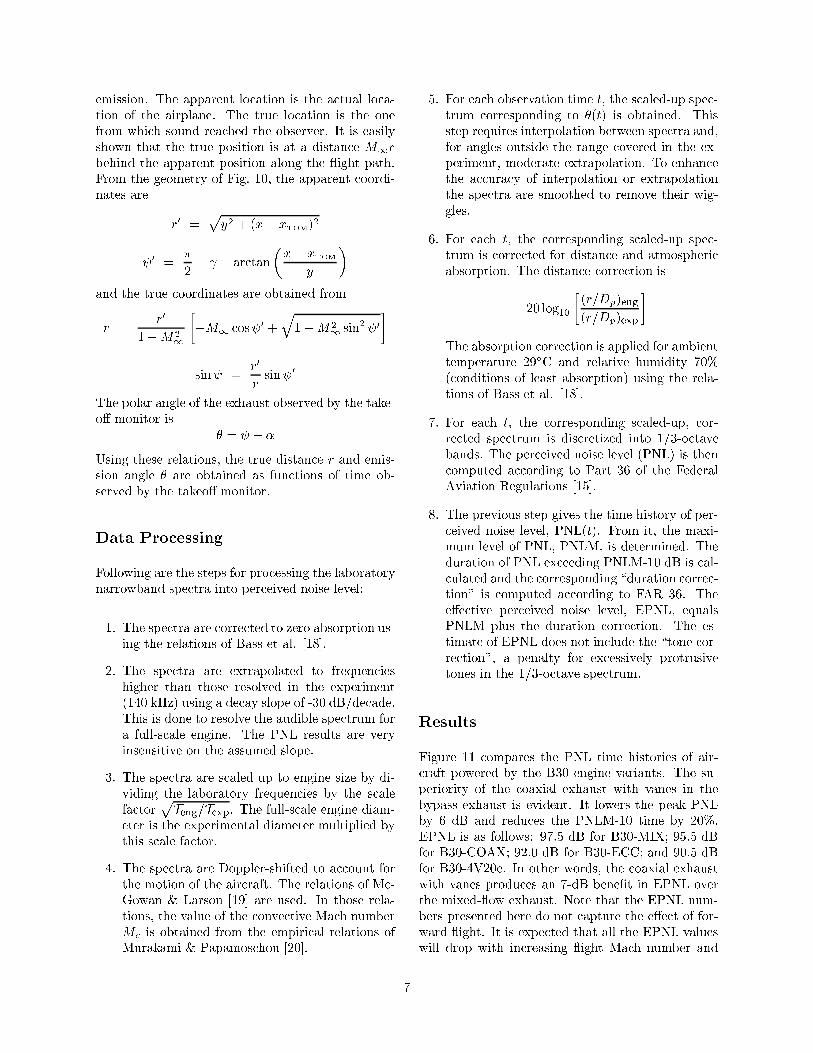
5. For each observation time t, the scaled-up spec-
trum corresponding to �(t) is obtained. This
step requires interpolation between spectra and,
for angles outside the range covered in the ex-
periment, moderate extrapolation. To enhance
the accuracy of interpolation or extrapolation
the spectra are smoothed to remove their wig-
gles.
6. For each t, the corresponding scaled-up spec-
trum is corrected for distance and atmospheric
absorption. The distance correction is
�20 log10
�(r=Dp)eng
(r=Dp)exp
�
The absorption correction is applied for ambient
temperature 29ÆC and relative humidity 70%
(conditions of least absorption) using the rela-
tions of Bass et al. [18].
7. For each t, the corresponding scaled-up, cor-
rected spectrum is discretized into 1/3-octave
bands. The perceived noise level (PNL) is then
computed according to Part 36 of the Federal
Aviation Regulations [15].
8. The previous step gives the time history of per-
ceived noise level, PNL(t). From it, the maxi-
mum level of PNL, PNLM, is determined. The
duration of PNL exceeding PNLM-10 dB is cal-
culated and the corresponding \duration correc-
tion" is computed according to FAR 36. The
e�ective perceived noise level, EPNL, equals
PNLM plus the duration correction. The es-
timate of EPNL does not include the \tone cor-
rection", a penalty for excessively protrusive
tones in the 1/3-octave spectrum.
Results
Figure 11 compares the PNL time histories of air-
craft powered by the B30 engine variants. The su-
periority of the coaxial exhaust with vanes in the
bypass exhaust is evident. It lowers the peak PNL
by 6 dB and reduces the PNLM-10 time by 20%.
EPNL is as follows: 97.5 dB for B30-MIX; 95.5 dB
for B30-COAX; 92.0 dB for B30-ECC; and 90.5 dB
for B30-4V20e. In other words, the coaxial exhaust
with vanes produces an 7-dB bene�t in EPNL over
the mixed- ow exhaust. Note that the EPNL num-
bers presented here do not capture the e�ect of for-
ward ight. It is expected that all the EPNL values
will drop with increasing ight Mach number and
7
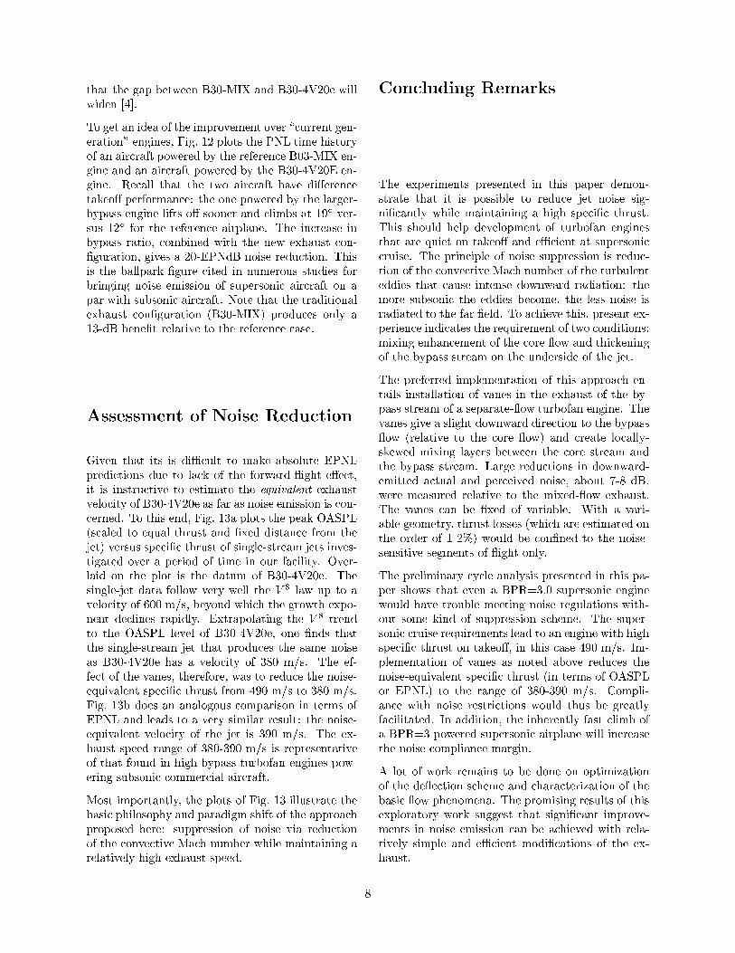
that the gap between B30-MIX and B30-4V20e will
widen [4].
To get an idea of the improvement over \current gen-
eration" engines, Fig. 12 plots the PNL time history
of an aircraft powered by the reference B03-MIX en-
gine and an aircraft powered by the B30-4V20E en-
gine. Recall that the two aircraft have di�erence
takeo� performance: the one powered by the larger-
bypass engine lifts o� sooner and climbs at 19Æ ver-
sus 12Æ for the reference airplane. The increase in
bypass ratio, combined with the new exhaust con-
�guration, gives a 20-EPNdB noise reduction. This
is the ballpark �gure cited in numerous studies for
bringing noise emission of supersonic aircraft on a
par with subsonic aircraft. Note that the traditional
exhaust con�guration (B30-MIX) produces only a
13-dB bene�t relative to the reference case.
Assessment of Noise Reduction
Given that its is diÆcult to make absolute EPNL
predictions due to lack of the forward- ight e�ect,
it is instructive to estimate the equivalent exhaust
velocity of B30-4V20e as far as noise emission is con-
cerned. To this end, Fig. 13a plots the peak OASPL
(scaled to equal thrust and �xed distance from the
jet) versus speci�c thrust of single-stream jets inves-
tigated over a period of time in our facility. Over-
laid on the plot is the datum of B30-4V20e. The
single-jet data follow very well the V 8 law up to a
velocity of 600 m/s, beyond which the growth expo-
nent declines rapidly. Extrapolating the V 8 trend
to the OASPL level of B30-4V20e, one �nds that
the single-stream jet that produces the same noise
as B30-4V20e has a velocity of 380 m/s. The ef-
fect of the vanes, therefore, was to reduce the noise-
equivalent speci�c thrust from 490 m/s to 380 m/s.
Fig. 13b does an analogous comparison in terms of
EPNL and leads to a very similar result: the noise-
equivalent velocity of the jet is 390 m/s. The ex-
haust speed range of 380-390 m/s is representative
of that found in high-bypass turbofan engines pow-
ering subsonic commercial aircraft.
Most importantly, the plots of Fig. 13 illustrate the
basic philosophy and paradigm shift of the approach
proposed here: suppression of noise via reduction
of the convective Mach number while maintaining a
relatively high exhaust speed.
Concluding Remarks
The experiments presented in this paper demon-
strate that it is possible to reduce jet noise sig-
ni�cantly while maintaining a high speci�c thrust.
This should help development of turbofan engines
that are quiet on takeo� and eÆcient at supersonic
cruise. The principle of noise suppression is reduc-
tion of the convective Mach number of the turbulent
eddies that cause intense downward radiation: the
more subsonic the eddies become, the less noise is
radiated to the far �eld. To achieve this, present ex-
perience indicates the requirement of two conditions:
mixing enhancement of the core ow and thickening
of the bypass stream on the underside of the jet.
The preferred implementation of this approach en-
tails installation of vanes in the exhaust of the by-
pass stream of a separate- ow turbofan engine. The
vanes give a slight downward direction to the bypass
ow (relative to the core ow) and create locally-
skewed mixing layers between the core stream and
the bypass stream. Large reductions in downward-
emitted actual and perceived noise, about 7-8 dB,
were measured relative to the mixed- ow exhaust.
The vanes can be �xed of variable. With a vari-
able geometry, thrust losses (which are estimated on
the order of 1-2%) would be con�ned to the noise-
sensitive segments of ight only.
The preliminary cycle analysis presented in this pa-
per shows that even a BPR=3.0 supersonic engine
would have trouble meeting noise regulations with-
out some kind of suppression scheme. The super-
sonic cruise requirements lead to an engine with high
speci�c thrust on takeo�, in this case 490 m/s. Im-
plementation of vanes as noted above reduces the
noise-equivalent speci�c thrust (in terms of OASPL
or EPNL) to the range of 380-390 m/s. Compli-
ance with noise restrictions would thus be greatly
facilitated. In addition, the inherently fast climb of
a BPR=3 powered supersonic airplane will increase
the noise compliance margin.
A lot of work remains to be done on optimization
of the de ection scheme and characterization of the
basic ow phenomena. The promising results of this
exploratory work suggest that signi�cant improve-
ments in noise emission can be achieved with rela-
tively simple and eÆcient modi�cations of the ex-
haust.
8

Special Notice
The method and apparatus of noise suppression via
de ection of the bypass and/or core streams is pro-
prietary to the University of California. U.S. Patent
Pending.
Acknowledgments
The support by NASA Glenn Research Center is
gratefully acknowledged (Grant NAG-3-2345 mon-
itored by Dr. Khairul B. Zaman). Ms. Erin Abbey
is thanked for her work on nozzle design.
References
[1] Smith, M.J.T., \Aircraft Noise", 1st Ed., Cam-
bridge University Press, 1989, pp. 120-134.
[2] Tillman, T.G., Paterson, R.W., and Presz,
W.M., \Supersonic Nozzle Mixer Ejector",
AIAA Journal of Propulsion and Power, Vol.
8, No. 2, 1992, pp. 513-519.
[3] Papamoschou, D. and Debiasi, M., \Mach
Wave Elimination Applied to Turbofan En-
gines," AIAA-2002-0368.
[4] Papamoschou, D., \Noise Suppression in
Moderate-Speed Multistream Jets," AIAA-
2002-2557.
[5] Mair, W.A. and Birdsall, D.L., \Aircraft Per-
formance," 1st Ed., Cambridge Aerospace Se-
ries 5, 1992, pp. 260-261.
[6] Horlock, J.H., Watson, D.T., and Jones, T.V.,
\Limitations on Gas Turbine Performance Im-
posed by Large Turbine Cooling Flows," Jour-
nal of Engineering for Gas Turbines and
Power," Vol. 123, July 2001, pp. 487-494.
[7] Debiasi, M., and Papamoschou, D., \Cycle
Analysis for Quieter Supersonic Turbofan En-
gines," AIAA-2001-3749.
[8] Lord, W.K., MacMartin, D.G., and Tillman,
T.G., \Flow Control Opportunities in Gas Tur-
bine Engines," AIAA-2000-2234.
[9] Guha, A. \Optimum Fan Pressure Ratio for By-
pass Engines with Separate or Mixed Flow Ex-
haust Streams," AIAA Journal of Propulsion
and Power, Vol. 17, No. 5, 2001, pp. 1117-1122.
[10] Papamoschou, D., and Debiasi, M., \Direc-
tional Suppression of Noise from a High-Speed
Jet," AIAA Journal, Vol. 39, No. 3, 2001, pp.
380-387.
[11] Murakami, E., and Papamoschou, D. \Mean
Flow Development of Dual-Stream Compress-
ible Jets," AIAA Journal, Vol. 40, No. 6, 2002,
pp. 1131-1138.
[12] Kinzie, K.W., and McLaughlin, D.K., \Mea-
surements of Supersonic Helium/Air Mixture
Jets," AIAA Journal, Vol. 37, No. 11, 1999, pp.
1363-1369.
[13] Papamoschou, D., and Debiasi, M. \Noise Mea-
surements in Supersonic Jets Treated with the
Mach Wave Elimination Method," AIAA Jour-
nal, Vol. 37, No. 2, 1999, pp. 154-160.
[14] Hoch, R.G. and Berthelot, M., \Use of the
Bertin Aerotrain for the Investigation of Flight
E�ects on Aircraft Engine Exhaust Noise,"
Journal of Sound and Vibration, Vol. 54, No.
2, 1977, pp. 153-172.
[15] Federal Aviation Regulations Part 36 - Noise
Standards: Aircraft Type and Airwowrthiness
Certi�ciation.
[16] Bertin, J.J. and Smith, M.L., \Aerodynamics
for Engineers," 3rd Ed., Prentice Hall, 1998, pp.
319-321.
[17] Shevell, R.S., \Fundamentals of Flight," Pren-
tice Hall, 1989, pp. 265, 293.
[18] Bass, H.E., Sutherland, L.C., Zuckerwar, A.J.,
Blackstock, D.T., and Hester, D.M., \Atmo-
spheric Absorption of Sound: Further Devel-
opments, " Journal of the Acoustical Society of
America, Vol. 97, 1995, pp. 680-683.
[19] McGowan, R.S. and Larson, R.S., \Relation-
ship Between Static, Flight and Simulated
Flight Jet Noise Measurements," AIAA Jour-
nal, Vol. 22, No. 4, 1984, pp. 460-464.
[20] Murakami, E., and Papamoschou, D., \ Eddy
Convection in Supersonic Coaxial Jets," AIAA
Journal, Vol. 38, No.4, 2000, pp. 628-635.
9
(a)
0.950
0.975
1.000
1.025
1.050
1.075
1.100
1400 1600 1800 2000 2200
TIT (K)
TSF
C
BPR=3.0FPR=2.25OPR=20
(b)
1.00
1.20
1.40
1.60
1.80
2.00
1400 1600 1800 2000 2200
TIT (K)
Dfa
n(m
)
BPR=3.0FPR=2.25OPR=20
Fig.1 Variation of (a) thrust speci�c fuel con-
sumption and (b) fan diameter with turbine inlet
temperature for an engine developing 24 kN of
thrust at ight Mach number 1.6.
Fig.2 Isocontours of TSFC on the BPR-FPR
plane for M1 = 1:6. TIT=1800Æ and OPR=20.
Dot indicates current design.
10

(a)
(b)
(c)
Fig.3 Exemplary illustrations of the separate- ow
exhaust con�gurations considered in this study:
(a) clean coaxial; (b) eccentric; and (c) coaxial
with bypass de ectors.
Fig.4 Schlieren images of exhaust ow. Upper:
clean coaxial nozzle. Lower: coaxial nozzle with
four vanes installed immediately downstream of
the bypass duct. From Ref. [4].
Fig.5 Picture of nozzle B30-4V20e.
11

�
� � � � � � �� � � � � � �
� � � � � � � � �� � � � � � � � � �
� � � � � � � � � � � � � � ! " # � $ � % � &
' � � � ( � % � � ( ) � � � � �* � � ( � � � + � � % � � & �+ % � � � � � � � � (
" � � � � � � % ( $ � � � � � � � ) � � � � � ) � � � � � (
�
Fig.6 Experimental setup with set of polar angles
covered.
(a)
45
55
65
75
85
10 100 1000 10000Frequency (Hz)
SPL
(dB
/Hz)
B30-COAX
B30-ECC
B30-4V20e
(b)
45
55
65
75
85
10 100 1000 10000Frequency (Hz)
SPL
(dB
/Hz)
B30-MIX
B30-4V20e
Fig.7 Far-�eld, scaled-up spectra in the direc-
tion of peak emission (� = 30Æ) for the B30 vari-
ants. (a) Comparison among the separate- ow
variants; (b) comparison between B30-4V20e and
B30-MIX.
12

(a)
50
55
60
65
70
10 100 1000 10000Frequency (Hz)
SPL
(dB
/Hz)
B30-COAX
B30-ECC
B30-4V20e
(b)
50
55
60
65
70
10 100 1000 10000Frequency (Hz)
SPL
(dB
/Hz)
B30-MIX
B30-4V20e
Fig.8 Far-�eld, scaled-up spectra in the lateral
direction (� = 90Æ) for the B30 variants. (a) Com-
parison among the separate- ow variants; (b)
comparison between B30-4V20e and B30-MIX.
90
95
100
105
110
115
10 30 50 70 90 110 130
θ (deg)
OA
SP
L(d
B)
B30-COAXB30-MIXB30-ECCB30-4V20e
Fig.9 Directivity of overall sound pressure level
for the B30 variants.
� �
�� � � �
� � � �
�
� � � � � ��
�
�
�
�
� � � � � � � � � � � � �
Fig.10 Flight path used for estimating perceived
noise level.
70
75
80
85
90
95
100
40 50 60 70 80 90 100 110
Time from liftoff (s)
PNL
(dB
)
B30-MIX
B30-COAX
B30-ECC
B30-4V20e
Fig.11 Time history of yover perceived noise
level (PNL) of aircraft powered by the B30 vari-
ants.
13

70
80
90
100
110
120
30 40 50 60 70 80 90 100
Time from liftoff (s)
PNL
(dB
)
B03-MIX
B30-4V20e
Fig.12 Time history of yover perceived noise
level for aircraft powered by B03-MIX and B30-
4V20e.
(a)
100
105
110
115
120
0 0.1 0.2 0.3 0.4
log [(Specific Thrust)/a ∞]
OA
SPL
max
(r=
1000
',
T
=30
000
lb)(
dB) Single-jet data
B30-4V20e
V^8 law
380 m/s 490 m/s
(b)
85
90
95
100
105
110
0 0.1 0.2 0.3 0.4
log [(Specific Thrust)/a ∞]
EP
NL
Single-jet dataB30-4V20e
V^8 law
390 m/s 490 m/s
Fig.13 Comparison of the noise emission of B30-
4V20e with that of single-stream jets. (a)
OASPL; (b) EPNL.
14