Embed Size (px)
Citation preview

American Institute of Aeronautics and Astronautics
1
AIAA-2001-0253
FLIGHT CONTROL OF A SPIN STABILISED AXI-SYMMETRIC DISC-WING
Jonathan R. Potts* & William J. Crowther†
Fluid Mechanics Research Group, School of Engineering,University of Manchester, U.K.
Abstract
A review of air-vehicles with circular planform ie disc-wings includes examples of mid-20th century innovationand recent developments in UAV (unnamed air vehicle)technology. A spin stabilised axi-symmetric disc-winghas potential application as a highly manoeuvrable,unpowered unmanned air vehicle or guided projectile.This paper considers the means by which aerodynamiccontrol moments can be generated on such a disc-wing.The present experimental investigation outlines theaerodynamics of a spin stabilised axi-symmetric disc-wing and documents the aerodynamic differences of adisc-wing with forced transition strips installed on thedisc rim. It is proposed that these differences areachievable by a similar active flow control method suchas active turbulent strips, vortex generators or synthetic(massless) jets as a means to aerodynamic control of thedisc in flight. A simple analysis of disc-wing flightmanoeuvres predicts the turning radius and time periodof a 90° banked turn based on experimental data.
Nomenclature
AoA Angle of attack (°)AdvR Advance ratio (ΩπDd / V)AR Aspect ratioCL Lift coefficientCD Drag coefficientCDo Profile drag coefficientCM Pitching moment coefficientCR Rolling moment coefficientDd Disc diameter (m)Rd Disc radius (m)Td Disc thickness (m)g Acceleration due to gravity (ms-2)Lf Lift (N)H Angular momentum (Kg m2 s)I Moment of inertia (Kg m2)Md Mass of disc-wing (Kg)q Precession rate (rad s-1)
_____________________* Research Student, Goldstein Res. Lab., Student Member AIAA.† Lecturer, Division of Aerospace Engineering.Copyright © 2001 by J.R.Potts. Published by the American Instituteof Aeronautics and Astronautics Inc. with permission.
Rc Radius of circular flightpath (m)S Surface planform area (m2)Re Reynolds numberT90 Time taken for a 90° turn (s)V Wind velocity (ms-1)V1,V2 Trailing vorticesx,y,z Roll, pitch, yaw axesL,M,N Rolling, pitching, yawing moments (Nm)p,q,r Rates of roll, pitch, yaw (rad s-1)ρ Density of air (Kg m-3)ωo Angular velocity (rad s-1)ωs Spin rate (rad s-1)Ω Spin rate (Hz)
Introduction
In its simplest form a disc-wing can be described as anaxi-symmetric flat plate or a cylinder of approximatelyzero height but is more broadly defined as a circularplanform wing. The concept of a circular planformflying wing (XF-5U-1) was developed during the 1930s& 40s based on a family of three dimensional circularwings with cross-sectional profile based on Clark Yairfoils1. In the 1950s a circular VTOL (vertical take offand landing) air-vehicle known as the Avrocar (VZ-9AV) was developed with a central ‘turborotor’ whichgenerated lift and control forces through a combinationof annular nozzles and peripheral jets. In 1972 the U.S.Navy commissioned a project to further thedevelopment of a spin stabilised self-suspended flare2,3,which was essentially an axi-symmetric cambered wingwith circular planform. With the recent development ofsuch a wide variety of UAV (unmanned air vehicle)body shapes it is not surprising to find the re-emergenceof the disc-wing. The ‘Cypher’ VTOL UAV withcircular planform encompasses a central rotor andducted airstream similar to the Avrocar. Slightlysmaller is a silicon wafer integrated MAV (micro airvehicle) under development by Washabaugh et al4. Anarray of Helmholtz resonators distributed over a thindisc-plate, harness synthetic jet technology to provideboth lift and control. The authors are conducting anexperimental investigation into the aerodynamics andcontrol of a spin stabilised axi-symmetric disc-wing as

American Institute of Aeronautics and Astronautics
2
part of an ongoing research program to develop a disc-wing UAV. This type of vehicle has potentialapplication as a highly manoeuvrable unpowered UAVor guided projectile. This configuration will typically beunstable in pitch and for practical purposes must beinertially stabilised by spinning. Such a disc has nopredefined flight orientation and offers potentiallynovel flight characteristics. Previous work by theauthors outlined the aerodynamics of a Frisbee-likeconfiguration5 and visualised the flow field usingsurface paint and smoke wire techniques5,6.Independently Higuchi et al7 investigated the flow overa similar disc-wing using smoke wire flow visualisationand PIV (particle image velocimetry) measurementsaiming to provide information for possible UAVapplications. Once an understanding of theaerodynamics has been gained the next stage in thedevelopment of a disc-wing UAV is to investigatemethods of aerodynamic control.
As an introduction to the dynamics of disc-wing flightconsider Fig. 1a. Note that for a Frisbee-like shape attypical flight angles of attack, the centre of pressure cpof the disc-wing is ahead of the centre of the disc i.e.ahead of the disc cg. This results in an untrimmed noseup pitching moment. If the disc is rotating, gyroscopiceffects dictate that this pitching moment results in aprecessional rolling rate, p. Thus spin providesenhanced pitch stiffness at the expense of roll stability.Using the conventional body fixed axes definition (Fig1b), for a disc rotating in the direction of positive yawthen a positive pitching moment will generate anegative roll rate.
Fig. 1. (a) Disc-wing flight dynamics. (b) Schematicdiagram of body fixed axes.
Aerodynamic control modifies the flow solution arounda vehicle providing useful forces and moments to alterthe flight trajectory and attitude in a desired way.Conventionally this is achieved by varying bodygeometry, intelligent positioning of small geometricchanges can produce large flow changes resulting incontrol forces of useful magnitude. In the example of anairfoil, the aerodynamic forces acting on the liftingsurface are controlled by the deflection of a trailingedge flap, this is also highly efficient as the powerrequired to generate the control forces is small. Other,perhaps more unconventional, methods of flow controlhave been developed over recent years to improveaerodynamic performance and provide novel ways ofgenerating control forces. Some examples of these areadaptive structures, tangential blowing and boundarylayer mixing devices such as vortex generators8 orsynthetic9 (massless) jets. As a solution to the problemof controlling a disc-wing UAV in flight, it is proposedthat flow control methods will be used to modify theaerodynamic forces and moments rather thanconventional moving surfaces. More specificallylooking towards active flow control methods such asvortex generators jets or tangential blowing. With thecomplexity of a disc with added rotation an active fluidcontrol method must ideally have the ability to respondrapidly to influence the flow in a cyclical manner.Proposed control methods for further investigation are:
Geometric ModificationGeometry can be modified locally through deflection ofaerodynamic surfaces or globally through shape controlapplied to the whole body. Global geometric controlhas the advantage that no extra aerodynamic surfacesare required, however an actuation system able tocyclically camber and twist the disc is likely to becomplex. A potential solution is to design a flexiblestructure with active stiffness provided by embeddedpiezoceramic actuators.
Separation ControlAs a boundary layer approaches separation the velocitygradient on the body surface tends towards zero. If thefluid within the boundary layer can be givenmomentum downstream of the separation then it maybe possible to delay or prevent separation. An effectivedelay in separation will alter the local pressuredistribution and therefore modify the loads providing amethod of aerodynamic control. Separation control isachieved by the addition of high momentum fluid to thenear wall boundary layer or the removal of lowmomentum fluid from the near wall boundary layer.Two methods which make this possible are increasedboundary layer mixing and tangential blowing/suction,the former requiring zero net mass-flow.
(a)
(b)
American Institute of Aeronautics and Astronautics
3
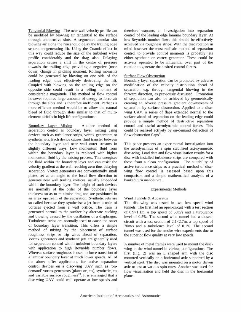
Tangential Blowing – The near wall velocity profile canbe modified by blowing air tangential to the surfacethrough unobtrusive slots. A segmented annular slotblowing air along the rim should delay the trailing edgeseparation generating lift. Using the Coanda effect inthis way could reduce the size of the turbulent wakeprofile considerably and the drag also. Delayingseparation causes a shift in the centre of pressuretowards the trailing edge providing a negative (nosedown) change in pitching moment. Rolling momentscould be generated by blowing on one side of theleading edge, thus effectively destroying the lift.Coupled with blowing on the trailing edge on theopposite side could result in a rolling moment ofconsiderable magnitude. This method of flow controlhowever requires large amounts of energy to force airthrough the slots and is therefore inefficient. Perhaps amore efficient method would be to allow the naturalbleed of fluid through slots similar to that of multi-element airfoils in high lift configurations.
Boundary Layer Mixing – Another method ofseparation control is boundary layer mixing usingdevices such as turbulence strips, vortex generators orsynthetic jets. Each device causes fluid transfer betweenthe boundary layer and near wall outer streams inslightly different ways. Low momentum fluid fromwithin the boundary layer is replaced with highermomentum fluid by the mixing process. This energisesthe fluid within the boundary layer and can resist thevelocity gradient at the wall reaching zero thus delayingseparation. Vortex generators are conventionally smallplates set at an angle to the local flow direction togenerate near wall trailing vortices, usually embeddedwithin the boundary layer. The height of such devicesare normally of the order of the boundary layerthickness so as to minimise drag and are positioned inan array upstream of the separation. Synthetic jets areso called because they synthesise a jet from a train ofvortices ejected from a wall orifice. The train isgenerated normal to the surface by alternate suckingand blowing caused by the oscillation of a diaphragm.Turbulence strips are normally used to cause the onsetof boundary layer transition. This offers a simplemethod of mixing by the placement of surfaceroughness strips or trip wires ahead of separation.Vortex generators and synthetic jets are generally usedfor separation control within turbulent boundary layerswith application to high Reynolds number flows.Whereas surface roughness is used to force transition ofa laminar boundary layer at much lower speeds. All ofthe above offer applications for active separationcontrol devices on a disc-wing UAV such as ‘on-demand’ vortex generators (plates or jets), synthetic jetsand variable surface roughness10. It is envisaged that adisc-wing UAV could well operate at low speeds and
therefore warrants an investigation into separationcontrol of the leading edge laminar boundary layer. Atlow Reynolds number flows this should be effectivelyachieved via roughness strips. With the disc rotation inmind however the most realistic method of separationcontrol to provide control moments is probably jetseither synthetic or vortex generator. These could beactively operated to be influential over part of therotation to generate the desired control forces.
Surface Flow ObstructionBoundary layer separation can be promoted by adversemodification of the velocity distribution ahead ofseparation e.g. through tangential blowing in theforward direction, as previously discussed. Promotionof separation can also be achieved by geometricallycreating an adverse pressure gradient downstream ofseparation by surface obstruction. Applied to a disc-wing UAV, a series of flaps extended normal to thesurface ahead of separation on the leading edge couldprovide a simple method of destructive separationcontrol and useful aerodynamic control forces. Thiscould be realised actively by on-demand deflection offlow obstruction flaps11.
This paper presents an experimental investigation intothe aerodynamics of a spin stabilised axi-symmetricdisc-wing. Load data and flow visualisation results for adisc with installed turbulence strips are compared withthose from a clean configuration. The suitability ofactive turbulence strips as a practical method of disc-wing flow control is assessed based upon thiscomparison and a simple mathematical analysis of abanked turn manoeuvre.
Experimental Methods
Wind Tunnels & ApparatusThe disc-wing was tested in two low speed windtunnels: The first had an open-circuit with a test sectionof 0.9×1.1m, a top speed of 50m/s and a turbulencelevel of 0.5%. The second wind tunnel had a closed-circuit with a test section of 2.1×2.7m, a top speed of70m/s and a turbulence level of 0.1%. The secondtunnel was used for the smoke wire experiments due tothe superior flow quality at very low speeds.
A number of metal frames were used to mount the disc-wing in the wind tunnel in various configurations. Thefirst (Fig. 2) was an L shaped arm with the discmounted vertically on a horizontal axle supported by avertical strut. The disc was mounted on a motor drivenaxle to test at various spin rates. Another was used forflow visualisation and held the disc in the horizontalplane.

American Institute of Aeronautics and Astronautics
4
Fig. 2 The rig supporting a disc-wing, at incidence, inthe wind tunnel.
The disc-wing cross-sectional profile can be seen inFig. 3. The aspect ratio, AR, for a circular planform is4/π ≈ 1.27. For the discs tested, the centre line thicknessto chord ratio T/D was 0.14, D = 0.275m.
Fig. 3 Cross-sectional disc-wing profile.
Transition or turbulence strips were fixed onto theupper surface of the disc-wing rim in the form of sevenboundary layer trip wires. The copper wire rings of1/2mm diameter were initially fixed onto the surfacewith super-glue laid 5mm apart, the first at a radius of112mm. A thick coat of paint was applied to the surfaceto affix the wires further.
Fig. 4 Disc-wing with installed turbulence strips.
Experimental Techniques - The aerodynamic loadswere measured by a six component overhead balance5.Surface paint flow visualisation used a kerosene-
fluorescent powder mix5,6. Vertical smoke wire forcontinuous oil supply and laser light sheet6.
Results and Discussion
Disc-wing AerodynamicsThe aerodynamic forces and moments acting on thedisc-wing are dependent upon speed, rotation rate andangle of attack. The loads were measured for the rangeof conditions that the disc-wing will experience in freeflight.
Clean Disc-wing The lift and drag trends for a cleandisc-wing are shown in Fig. 6a,b for Reynolds number,Re = 3.78×10⁵, equivalent to a flow speed of 20m/s,and advance ratio (rim speed to flow speed), AdvR = 0.The lift curve has slope 0.05 and the drag curve showsa minimum, CDo, of 0.09 at the zero lift angle, -3°incidence. The pitching moment curve (Fig. 6c) is non-linear and displays a negative (nose down) coefficientof -0.02 at the zero lift angle of attack (−3°). Zeropitching moment occurs at 8° incidence and provides anose up pitching moment for higher incidence. Therolling moment is essentially zero, which is as expectedfor a symmetrical body.
Visualisation of the flow over the upper and lowersurfaces of a clean disc at zero angle of attack is shownin Fig. 7. The upper surface pattern (Fig. 7a) shows thatthe surface flow direction is from the leading edgetowards L1, indicated by the streak lines within regionA. The boundary layer separates from the surfaceleaving a clearly visible line (L1) and the shear layerreattaches at L2. The boundary layer remains attachedthroughout region C and then separates off the surfaceat L3. A separation bubble is formed with reversed flow(from L2 to L1) on the surface and re-circulation withinregion B. From the trailing edge, a reversed surfaceflow pattern is observed within region D, as fluid isdrawn towards the stagnation line at L3. Two nodes atthe points V1,V2 indicate where trailing vortices detachfrom the surface. Streak lines in the vicinity of V1,V2
suggest that fluid from the separation bubble and frombeneath the cavity feeds into these vortices.
The general description of the cavity surface flow isgiven with reference to Fig. 7b. The cavity surfacepattern indicates that the boundary layer separates offthe leading edge lip and impinges on the inside of thetrailing edge rim leaving a stagnation line (whichcannot be seen on Fig. 7b). Reversed flow (F) existsfrom the trailing edge towards the stagnation line L4.The shear layer encloses a weakly circulatingseparation bubble (E). The reader is referred to
American Institute of Aeronautics and Astronautics
5
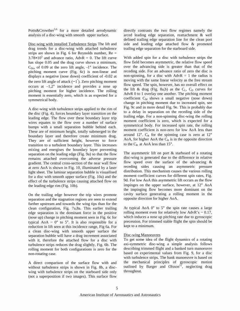
Potts&Crowther5,6 for a more detailed aerodynamicanalysis of a disc-wing with smooth upper surface.
Disc-wing with installed Turbulence Strips The lift anddrag trends for a disc-wing with attached turbulencestrips are shown in Fig. 6 for Reynolds number, Re =3.78×10⁵ and advance ratio, AdvR = 0. The lift curvehas slope 0.05 and the drag curve shows a minimum,CDo, of 0.09 at the zero lift angle, -1° incidence. Thepitching moment curve (Fig. 6c) is non-linear anddisplays a negative (nose down) coefficient of -0.02 atthe zero lift angle of attack (−1°). Zero pitching momentoccurs at –1,2° incidence and provides a nose uppitching moment for higher incidence. The rollingmoment is essentially zero, which is as expected for asymmetrical body.
A disc-wing with turbulence strips applied to the rim ofthe disc (Fig. 4), forces boundary layer transition on theleading edge. The flow over these boundary layer tripwires equates to the flow over a number of surfacebumps with a small separation bubble behind each.These are of minimum height, totally submerged in theboundary layer and therefore create minimum drag.They are of sufficient height, however to forcetransition to a turbulent boundary layer. This increasesmixing and energises the boundary layer preventingseparation on the leading edge (Fig. 9a) so that the flowremains attached overcoming the adverse pressuregradient. The central cross-section of the near wall flowat zero AoA is shown in Fig. 10, illuminated by a laserlight sheet. The laminar separation bubble is visuailisedfor a disc with smooth upper surface (Fig. 10a) and theeffect of the turbulence strips causing attached flow onthe leading edge rim (Fig. 10b).
On the trailing edge however the trip wires promoteseparation and the stagnation regions are seen to extendfurther upstream and towards the wing tips than for theclean configuration, Fig. 7a,8a. This earlier trailingedge separation is the dominant force in the positive(nose up) change in pitching moment seen in Fig. 6c fortypical AoA ~ 0° to 5°. It is also responsible for areduction in lift seen at this incidence range, Fig 6a. Fora clean disc-wing with smooth upper surface theseparation bubble will have a drag increment associatedwith it, therefore the attached flow for a disc withturbulence strips reduces the drag slightly, Fig. 6b. Therolling moment for both configurations is zero for thenon-rotating case.
A direct comparison of the surface flow with andwithout turbulence strips is shown in Fig. 8b, a disc-wing with turbulence strips on the starboard side only(not a superposition if two images). This surface flow
directly contrasts the two flow regimes namely thearced leading edge separation, reattachment & welldefined trailing edge separation line for the clean portside and leading edge attached flow & promotedtrailing edge separation for the starboard side.
With added spin for a disc with turbulence strips theflow field becomes asymmetric, the relative flow speedover the advancing side is greater than that of thereceding side. For an advance ratio of zero the disc isnon-spinning, for a disc with AdvR = 1 the radius ismoving with the same linear velocity as the free streamflow speed. The spin, however, has no overall effect onthe lift & drag (Fig. 8a,b) as the CL, CD curves forAdvR 0 to 1 overlay one another. The pitching momentcoefficient CM shows a small negative (nose down)change in pitching moment due to increased spin, seeFig. 9c and in more detail Fig. 9e. This is probably dueto a delay in separation on the receding side of thetrailing edge. For a non-spinning disc-wing the rollingmoment coefficient is zero, which is expected for asymmetrical body. For increased spin rate, the rollingmoment coefficient is non-zero for low AoA less thanaround 12°. CR for the spinning case is zero at 12°AoA, for higher AoA the CR is in the opposite directionto the CR at AoA less than 15°.
The asymmetric lift on port & starboard of a rotatingdisc-wing is generated due to the difference in relativeflow speed over the surface of the advancing &receding sides causing an asymmetric pressuredistribution. This mechanism causes the various rollingmoment coefficient curves for different spin rates, Fig.9d. For low AoA this asymmetric lift occurs as the flowimpinges on the upper surface, however, at 12° AoAthe impinging flow becomes more dominant on thecavity surface generating a rolling moment in theopposite direction for higher AoA.
At typical AoA 0° to 5° the spin rate causes a largerolling moment even for relatively low AdvR’s ~ 0.17,which induces a nose up pitching rate due to gyroscopicprecession. For trimmed stable flight the spin should bekept to a minimum.
Disc-wing ManoeuvresTo get some idea of the flight dynamics of a rotatingaxi-symmetric disc-wing a simple analysis followsdescribing trimmed flight and a banked turn manoeuvrebased on experimental values from Fig. 9, for a discwith turbulence strips. The bank manoeuvre is based onthe mechanical principles of gyroscopic motionoutlined by Barger and Olsson12, neglecting dragthroughout.
American Institute of Aeronautics and Astronautics
6
Trimmed Flight For trimmed flight the lift Lf generatedby a disc-wing must equal its weight Mdg,
gMSCV dL2
21 =ρ (1)
where ρ is the density of air, S the disc-wing planformarea πRd
2 based on the disc radius Rd, V is the flightspeed and CL the lift coefficient. For a standard plasticFrisbee-like disc-wing of 160grams and diameter Dd =0.275m the lift required for trimmed flight is Mdg =0.16×9.81 = 1.57N. At a flight speed of 20m/s this isachieved for a lift coefficient CL = 0.1 whichcorresponds to a 1° angle of attack.
Bank Manoeuvre Again for a standard plastic Frisbee-like disc-wing flying at a roll angle of 60°, to maintainthe same altitude for a banked turn the lift must supportits weight,
gMcos60L df =° (2)
At a flight speed of 20m/s this is achieved for a liftcoefficient CL = 0.1/cos60 = 0.2 which corresponds to a2° angle of attack.
The mass distribution of the disc-wing is concentratedin the outer rim, therefore the moment of inertia I isapproximated by assuming that the total mass is evenlydistributed along the circumference such that, I =MdRd
2. The angular momentum H in spin is thereforegiven by MdRd
2ωs about the spin axis, where ωs is thespin rate. The introduction of a disc-wing rollingmoment due to spin causes a pitch rate q (gyroscopicprecession) given by,
sILq ω= (3)
⇒ s
2dd
dR2
21
RM
R2SCVq
ωρ
= (4)
where L is the rolling moment based on experimentalparameter CR, the rolling moment coefficient. Thereforefor CR = 0.0044 at an AoA of 2° (Fig. 9) and AdvR =0.17 the pitch rate q is 0.233 which will take the disc6.7 seconds to turn through 90°.
The disc will describe a horizontal curved flightpathdue to the precession caused by the rolling moment andthe horizontal component of lift. To get an idea of thescale of this curved flight trajectory, assume that thedisc-wing describes a quarter circle with linear velocityV = 20m/s. In a circular flightpath the horizontalcomponent of lift balances the centrifugal force and the
angular velocity ω0 must match the precession rate psuch that,
0cRVq ω== (5)
From equations (4) and (5) a measure of the arc radiuscan be calculated rearranging for Rc,
R
sddc
VSC
RMR
ρω
= (6)
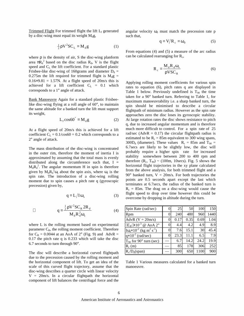
Applying rolling moment coefficients for various spinrates to equation (6), pitch rates q are displayed inTable 1 below. Previously undefined is T90 the timetaken for a 90° banked turn. Referring to Table 1, formaximum manoeuvrability i.e. a sharp banked turn, thespin should be minimised to describe a circularflightpath of minimum radius. However as the spin rateapproaches zero the disc loses its gyroscopic stability.At large rotation rates the disc shows resistance to pitchq, due to increased angular momentum and is thereforemuch more difficult to control. For a spin rate of 25rad/sec (AdvR = 0.17) the circular flightpath radius isestimated to be Rc = 85m equivalent to 300 wing spans,300Dd (diameter). These values Rc = 85m and T90 =6.7secs are likely to be slightly low, the disc willprobably require a higher spin rate for increasedstability somewhere between 200 to 400 rpm andtherefore (Rc, T90) ~ (100m, 10secs). Fig. 5 shows thehorizontal flight trajectories in the xy plane calculatedfrom the above analysis, for both trimmed flight and a90° banked turn, V = 20m/s. For both trajectories thepoints are 0.5 seconds apart except the last whichterminates at 6.7secs, the radius of the banked turn isRc = 85m. The drag on a disc-wing would cause theflight speed to drop over time however this could beovercome by dropping in altitude during the turn.
Spin Rate (rad/sec) 0 25 50 100 150
Rpm 0 240 480 960 1440AdvR (V = 20m/s) 0 0.17 0.35 0.69 1.04
CR×10-3 @ AoA 2° 0 4.4 4.2 4.9 8.9
Iωs×10-2 (kg m2 s-1) 0 7.6 15.1 30 45.4
q×10-2 (rad/sec) 0 23.3 11.1 6.5 7.9
T90 for 90° turn (sec) — 6.7 14.2 24.2 19.9Rc (m) — 85 178 306 252Rc/Dd(span) — 300 650 1100 900
Table 1 Various measures calculated for a banked turnmanoeuvre.

American Institute of Aeronautics and Astronautics
7
-10
10
30
50
70
90
0 50 100 150x (m)
y (m)
90 degreeturn to leftTrimmedflightpath
Fig. 5 Calculated disc-wing flight trajectories.
For low advance ratios of around 0.2 the rollingmoment for a disc without turbulence strips isapproximately zero5, for AoA around 2°. Whereas for adisc-wing with turbulence strips (Fig. 5) the rollingmoment is non-zero, which generates control forcescapable of producing a banked turn manoeuvre aspreviously described. If this degree of aerodynamiccontrol could be gained from active on/off turbulencestrips or some other method of control then that wouldoffer practical possibilities for aerodynamic control of adisc-wing UAV.
Conclusions
Proposed methods of both passive and active flowcontrol have been outlined with specific application to aspin stabilised axi-symmetric disc-wing. Furtherinvestigation in the form of a feasibility study isrequired to determine their effectiveness.
The comparison of the aerodynamics of a disc-wingwith installed passive turbulence strips and the cleanconfiguration, is insightful as a tentative prediction ofthe moments which could be produced by a similarmethod of active control using boundary layer mixingdevices such as on-demand control surfaces or syntheticjets.
The control forces generated by a disc-wing withinstalled turbulence strips are capable of producing abanked turn manoeuvre of around a 100m radius for therotating case. If this degree of aerodynamic controlcould be gained from active on/off turbulence strips orsome other method of control then that would offerpractical possibilities for aerodynamic control of a disc-wing UAV.
Acknowledgements
The authors would like to thank D. Mould at theGoldstein Research Laboratory for the skilledconstruction of the rig & disc. This research was fundedby the EPSRC, award reference number 98317373.
References
1Zimmerman, C.H., “Aerodynamic Characteristics ofSeveral Airfoils of Low Aspect Ratio”, NACATechnical Note, No.539, Aug. 1935.2Stilley G.D. & Carstens D.L., “Adaptation of FrisbeeFlight Principle to Delivery of Special Ordnance”,AIAA 72-982, AIAA 2nd Atmospheric FlightMechanics Conference, Palo Alto, California, USA,1972.3Stilley G.D., “Aerodynamic Analysis of the Self-suspended Flare” Honeywell Inc., NAD/Crane RDTRNo.199, AD740117, 23 Feb. 1972.4Washabaugh, P.D., Bernal, L.P., Najafi, K. et al, “AnApproach Toward Wafer Integrated Micro AirVehicle”, 15th International UAV Systems Conf.,Bristol, U.K., Apr. 2000.5Potts J.R. & Crowther W.J., “The Flow Over aRotating Disc-wing”, RAeS Aerodynamics ResearchConference Proc., London, UK, Apr. 2000.6Potts J.R. & Crowther W.J., “Visualisation of the FlowOver a Disc-wing”. Proc. of the Ninth InternationalSymposium on Flow Visualization, Edinburgh,Scotland, UK, 2000.7Higuchi H., Goto Y., Hiramoto R. & Meisel I.,“Rotating Flying Disks and Formation of TrailingVortices”, AIAA 2000-4001, 18th AIAA Applied Aero.Conf., Denver, CO, Aug. 2000.8Harrison T., Wood N.J. & Zhong S., “TurbulentSeparation Control Using Vortex Generators”, RAeSAerodynamics Research Conference Proc., London,UK, Apr. 2001.9Crook A. & Wood N.J., “Measurements andVisualisations of Synthetic Jets”, AIAA 2001-0145,39th Aero. Sci. Meet & Exhibit, Reno, NV, Jan. 2001.10C. Grosjean, G. Lee, W. Hong, Y.C. Tai & C.M. Ho,“Micro Balloon Actuators for Aerodynamic Control”,11th Ann. Int. Workshop on MEMS, Heidelberg,Germany, pp. 166-171, Jan. 1998.11Bauer, S.X.S., “An Aerodynamic Assessment ofMicro-Drag Generators (MDGs)”, AIAA 98-2621, 16th
AIAA Applied Aero. Conf., Albuquerque, NM, June1998.12Barger V. & Olsson M., “Classical Mechanics: AModern Perspective”, McGraw-Hill, New York, 1973.

American Institute of Aeronautics and Astronautics
8
-0.5
0
0.5
1
1.5
2
-10 0 10 20 30
Angle of Attack (degrees)
CL
w/o TurbStrps
w TurbStrps
0
0.2
0.4
0.6
0.8
1
-10 0 10 20 30Angle of Attack (degrees)
CD
w/o TurbStrps
w TurbStrps
-0.1
-0.05
0
0.05
0.1
0.15
-10 0 10 20 30
Angle of Attack (degrees)
CM
w/o TurbStrps
w TurbStrps
(c) Pitching moment coefficient.Fig. 6 Force and moment characteristics at zero spin rate for a disc-wing
with turbulence strips and the clean configuration, Re = 3.78×10⁵.
Fig. 7 The upper (a) and cavity (b) surface paint patterns for a clean disc-wing at 5° incidence, V = 15m/s.
(a) Lift coefficient. (b) Drag coefficient.

American Institute of Aeronautics and Astronautics
9
Fig. 8 The upper surface paint patterns for a disc-wing with installed turbulence strips on(a) port & starboard and (b) starboard only, at 5° incidence, V =20m/s.
-0.5
0
0.5
1
1.5
2
-10 0 10 20 30
Angle of Attack (degrees)
CL
AdvR 0.00AdvR 0.17AdvR 0.35AdvR 0.69AdvR 1.04
0
0.2
0.4
0.6
0.8
1
-10 0 10 20 30Angle of Attack (degrees)
CD
AdvR 0.00AdvR 0.17AdvR 0.35AdvR 0.69AdvR 1.04
(a) Lift coefficient. (b) Drag coefficient.
-0.05
0
0.05
0.1
0.15
-10 0 10 20 30
Angle of Attack (degrees)
CM
AdvR 0.00AdvR 0.17AdvR 0.35AdvR 0.69AdvR 1.04
-0.012
-0.008
-0.004
0
0.004
0.008
0.012
-10 0 10 20 30
Angle of Attack (degrees)
CR
AdvR 0.00AdvR 0.17AdvR 0.35AdvR 0.69AdvR 1.04
(c) Pitching moment coefficient. (d) Rolling moment coefficient.Fig. 9 Force and moment characteristics at various AdvRs for a disc-wing with turbulence strips, V = 20m/s.

American Institute of Aeronautics and Astronautics
10
-0.02
-0.01
0
0.01
0.02
0.03
0.04
0 2 4 6 8 10
Angle of Attack (degrees)
CM
AdvR 0.00AdvR 0.17AdvR 0.35AdvR 0.69AdvR 1.04
Fig. 9 cont. (e) Pitching moment coefficient (detail).
Fig. 10 Central cross-section of the (a) laminar separation bubble and (b) turbulent boundary layeron the leading edge of a non-rotating disc-wing at 0° incidence, V = 8m/s.