Embed Size (px)
Citation preview
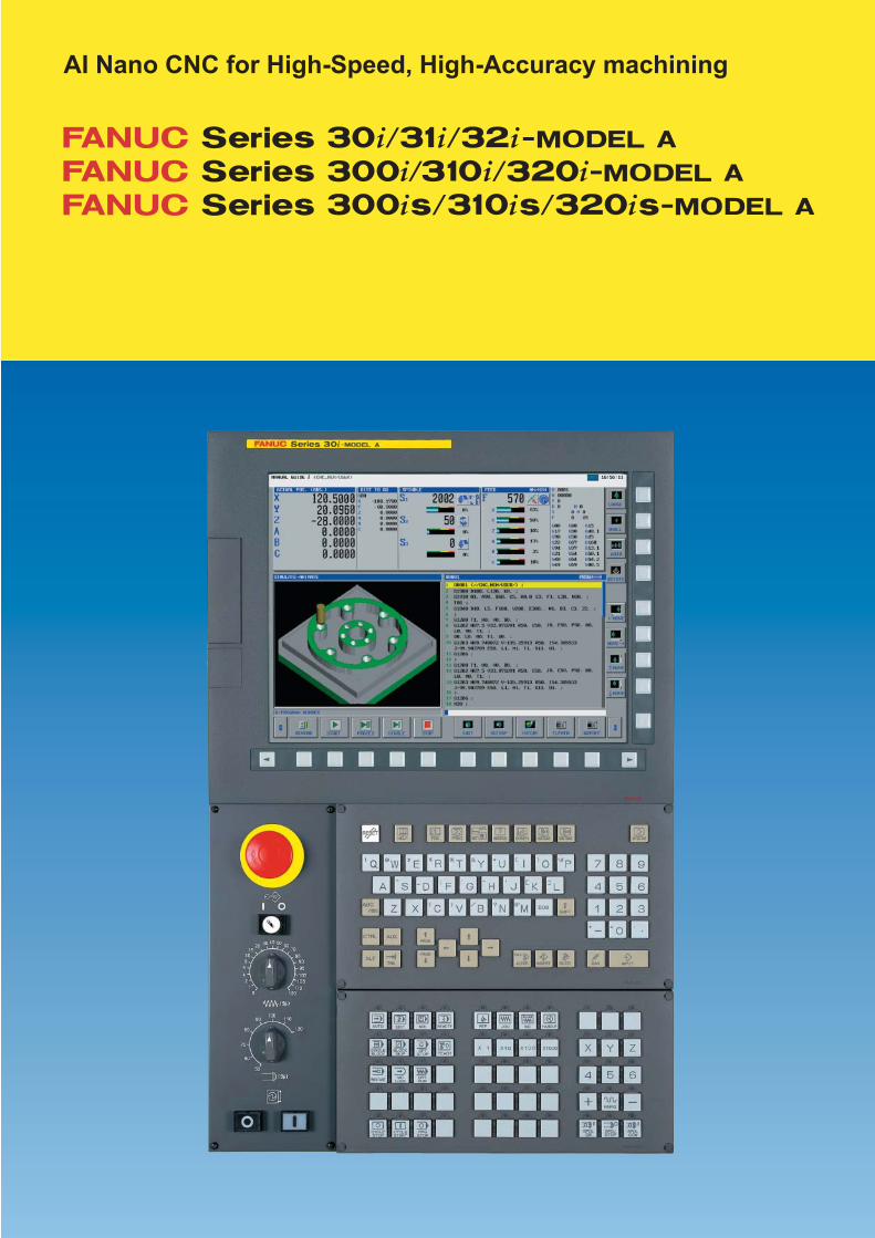
AI Nano CNC for High-Speed, High-Accuracy machining
2003
2 3
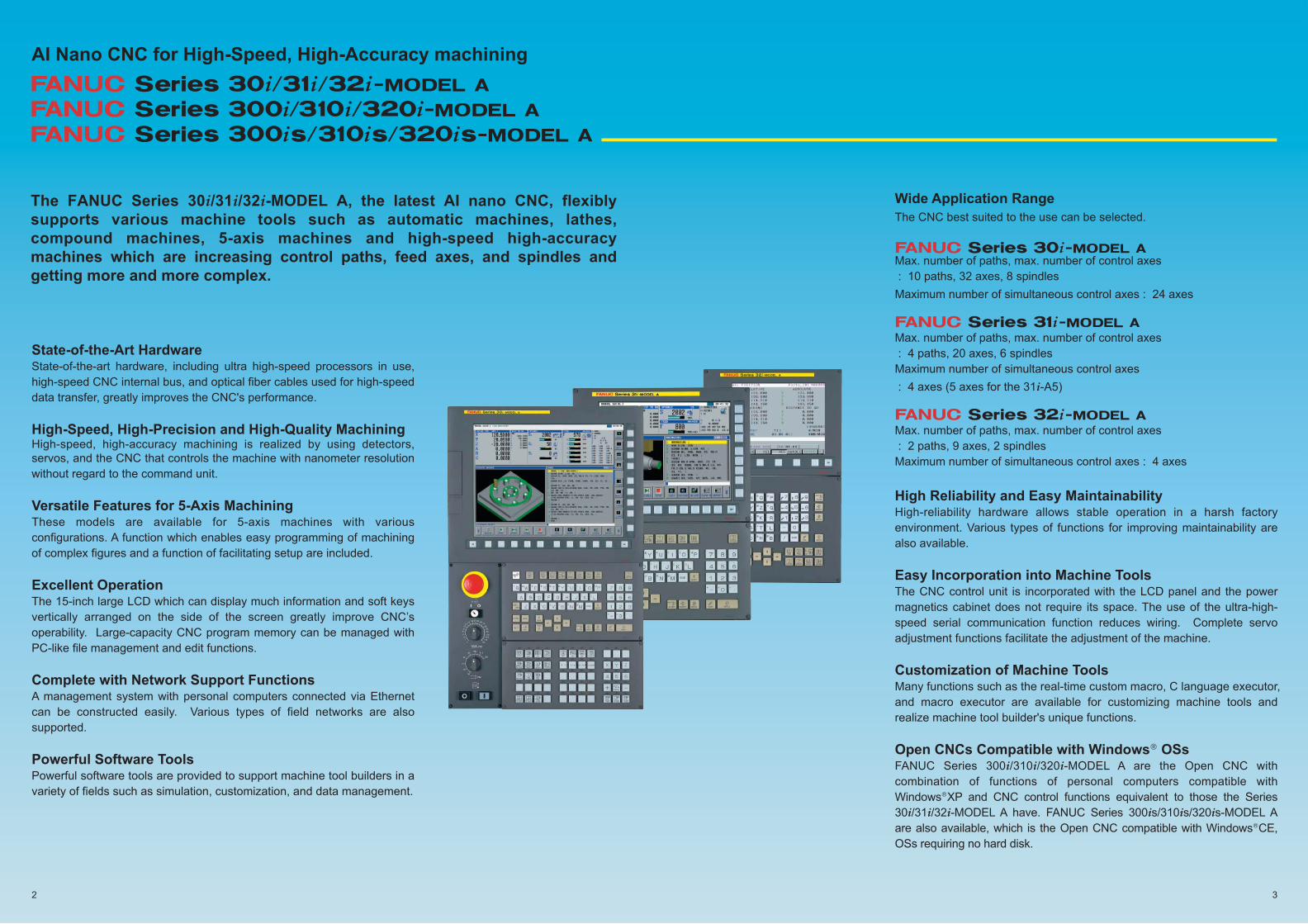
The FANUC Series 30i/31i/32i-MODEL A, the latest AI nano CNC, flexibly
supports various machine tools such as automatic machines, lathes,
compound machines, 5-axis machines and high-speed high-accuracy
machines which are increasing control paths, feed axes, and spindles and
getting more and more complex.
AI Nano CNC for High-Speed, High-Accuracy machining
State-of-the-Art Hardware State-of-the-art hardware, including ultra high-speed processors in use,
high-speed CNC internal bus, and optical fiber cables used for high-speed
data transfer, greatly improves the CNC's performance.
High-Speed, High-Precision and High-Quality Machining High-speed, high-accuracy machining is realized by using detectors,
servos, and the CNC that controls the machine with nanometer resolution
without regard to the command unit.
Versatile Features for 5-Axis MachiningThese models are available for 5-axis machines with various
configurations. A function which enables easy programming of machining
of complex figures and a function of facilitating setup are included.
Excellent Operation The 15-inch large LCD which can display much information and soft keys
vertically arranged on the side of the screen greatly improve CNC’s
operability. Large-capacity CNC program memory can be managed with
PC-like file management and edit functions.
Complete with Network Support FunctionsA management system with personal computers connected via Ethernet
can be constructed easily. Various types of field networks are also
supported.
Powerful Software ToolsPowerful software tools are provided to support machine tool builders in a
variety of fields such as simulation, customization, and data management.
Wide Application Range
The CNC best suited to the use can be selected.
Max. number of paths, max. number of control axes
: 10 paths, 32 axes, 8 spindles
Maximum number of simultaneous control axes : 24 axes
Max. number of paths, max. number of control axes
: 4 paths, 20 axes, 6 spindles
Maximum number of simultaneous control axes
: 4 axes (5 axes for the 31i-A5)
Max. number of paths, max. number of control axes
: 2 paths, 9 axes, 2 spindles
Maximum number of simultaneous control axes : 4 axes
High Reliability and Easy Maintainability High-reliability hardware allows stable operation in a harsh factory
environment. Various types of functions for improving maintainability are
also available.
Easy Incorporation into Machine Tools The CNC control unit is incorporated with the LCD panel and the power
magnetics cabinet does not require its space. The use of the ultra-high-
speed serial communication function reduces wiring. Complete servo
adjustment functions facilitate the adjustment of the machine.
Customization of Machine Tools Many functions such as the real-time custom macro, C language executor,
and macro executor are available for customizing machine tools and
realize machine tool builder's unique functions.
Open CNCs Compatible with Windows® OSs FANUC Series 300i/310i/320i-MODEL A are the Open CNC with
combination of functions of personal computers compatible with
Windows®XP and CNC control functions equivalent to those the Series
30i/31i/32i-MODEL A have. FANUC Series 300is/310is/320is-MODEL A
are also available, which is the Open CNC compatible with Windows®CE,
OSs requiring no hard disk.
Flexible Support of Various Mechanical Configurations
A single CNC can achieve complex control of a multi-path lathe with many turrets, compound machine tool with a milling head, or automatic lathe requiring many axes and command systems. In addition to supporting many paths and controlled axes, these series provide many functions required for multi-path control, such as synchronous/composite control, superimposed control, flexible axis assignment, waiting function, inter-path spindle function, and interference check for each path. A merger between high-speed, high-precision control technology that FANUC has nurtured over the years and multiaxis multipath control technology further promotes improvements in precision and efficiency of lathes and automatic lathes.
Multi-axis & Multi-path Lathe and Automatic Lathe
Loader control can also be controlled as a path, so no additional hardware component such as a loader-dedicated board is required. In much the same fashion as a CNC control path in a machining center system or lathe system, PMC axis control commands as well as G codes and custom macros can be specified. These functions promote streamlining and downsizing in a factory environment.
Loader Control Path
Flexible support for various machine configurations by expanded multi-axis and multi-path functionsFor the Series 30i/31i/32i-MODEL A, the maximum number of control axes, control paths, and spindles has been significantly expanded. In addition to support of many paths and controlled axes, these series provide many functions required for multi-path control, including axis synchronization and recomposition, superposition control, inter-path spindle control. These functions enable the flexible support for various machine configurations comprising a compact a machine tool, multi-path lathe, automatic machine, combined machine and other machines which have a different number of control paths and control axes.● Series 30i-A - 10 paths/32 feed axes/8 spindles● Series 31i-A - 4 paths/20 feed axes/6 spindles● Series 32i-A - 2 paths/ 9 feed axes/2 spindles
Compound Path Containing Machining Center, Lathe, and Loader Control SystemsMachining center, lathe, and loader control systems can be used for each path and selected without restrictions. Functions that were limited to the machining center system (or lathe system) are allowed for other systems, which increases the flexibility in machining within a path. With these functions, these series easily achieve control of compound machine tools with both milling and turning required.
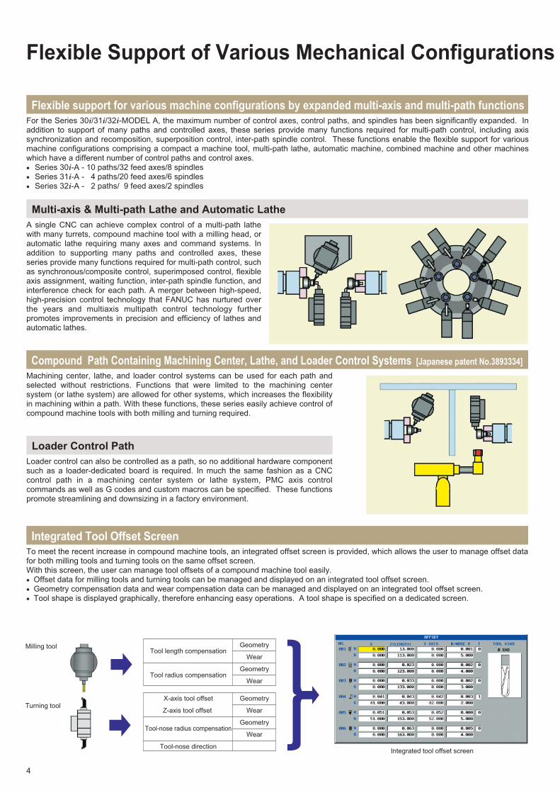
Integrated Tool Offset Screen To meet the recent increase in compound machine tools, an integrated offset screen is provided, which allows the user to manage offset data for both milling tools and turning tools on the same offset screen.With this screen, the user can manage tool offsets of a compound machine tool easily. ● Offset data for milling tools and turning tools can be managed and displayed on an integrated tool offset screen.● Geometry compensation data and wear compensation data can be managed and displayed on an integrated tool offset screen.● Tool shape is displayed graphically, therefore enhancing easy operations. A tool shape is specified on a dedicated screen.
Integrated tool offset screen
Geometry
Wear
Geometry
Wear
Tool length compensation
Tool radius compensation
Geometry
Wear
Geometry
Wear
X-axis tool offset
Z-axis tool offset
Tool-nose radius compensation
Tool-nose direction
Turning tool
Milling tool
[Japanese patent No.3893334]
4
L0° L180° L360°
X100.
X50.
X10.
With compound machine tools and 5-axis machines, complicated machining can be performed without making a workpiece setup change, so high machining efficiency can be achieved; however, programming for such machine tools is difficult, and interference between machine components such as a spindle and a table may occur during automatic operation and manual operation. A 3-dimensional interference check function is therefore provided to check for such interference in advance to enhance safety operation.
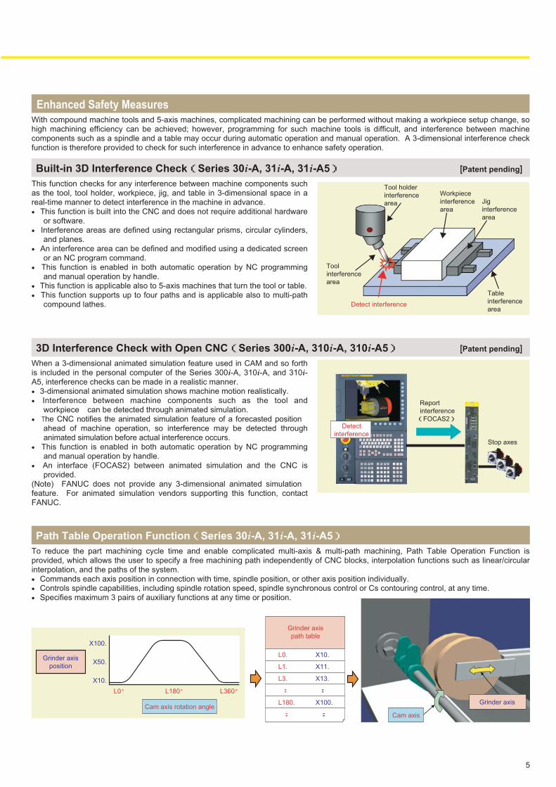
This function checks for any interference between machine components such as the tool, tool holder, workpiece, jig, and table in 3-dimensional space in a real-time manner to detect interference in the machine in advance. ● This function is built into the CNC and does not require additional hardware
or software. ● Interference areas are defined using rectangular prisms, circular cylinders,
and planes. ● An interference area can be defined and modified using a dedicated screen
or an NC program command. ● This function is enabled in both automatic operation by NC programming
and manual operation by handle. ● This function is applicable also to 5-axis machines that turn the tool or table.● This function supports up to four paths and is applicable also to multi-path
compound lathes.
Built-in 3D Interference Check(Series 30i-A, 31i-A, 31i-A5)
Enhanced Safety Measures
When a 3-dimensional animated simulation feature used in CAM and so forth is included in the personal computer of the Series 300i-A, 310i-A, and 310i-A5, interference checks can be made in a realistic manner. ● 3-dimensional animated simulation shows machine motion realistically. ● Interference between machine components such as the tool and
workpiece can be detected through animated simulation. ● The CNC notifies the animated simulation feature of a forecasted position
ahead of machine operation, so interference may be detected through animated simulation before actual interference occurs.
● This function is enabled in both automatic operation by NC programming and manual operation by handle.
● An interface (FOCAS2) between animated simulation and the CNC is provided.
(Note) FANUC does not provide any 3-dimensional animated simulation feature. For animated simulation vendors supporting this function, contact FANUC.
3D Interference Check with Open CNC(Series 300i-A, 310i-A, 310i-A5)
To reduce the part machining cycle time and enable complicated multi-axis & multi-path machining, Path Table Operation Function is provided, which allows the user to specify a free machining path independently of CNC blocks, interpolation functions such as linear/circular interpolation, and the paths of the system. ● Commands each axis position in connection with time, spindle position, or other axis position individually.● Controls spindle capabilities, including spindle rotation speed, spindle synchronous control or Cs contouring control, at any time.● Specifies maximum 3 pairs of auxiliary functions at any time or position.
Path Table Operation Function(Series 30i-A, 31i-A, 31i-A5)
Tool
interference
area
Tool holder
interference
area
Workpiece
interference
area
Jig
interference
area
Table
interference
area
Stop axes
Report
interference
(FOCAS2)
Detect interference
Detect
interference
Grinder axis
Cam axis
Cam axis rotation angle
Grinder axis
path table
L0.
L1.
L3.
:
L180.
:
X10.
X11.
X13.
:
X100.
:
Grinder axis
position
[Patent pending]
[Patent pending]
5
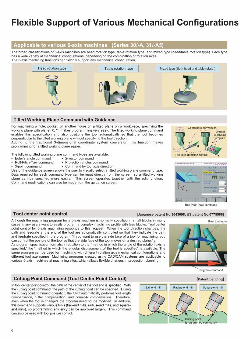
The broad classifications of 5-axis machines are head rotation type, table rotation type, and mixed type (head/table rotation type). Each type has a wide variety of mechanical configurations, depending on the combination of rotation axes.The 5-axis machining functions can flexibly support any mechanical configuration.
Table rotation type
Flexible Support of Various Mechanical Configurations
Although the machining program for a 5-axis machine is normally specified in small blocks in many cases, many users want to easily program a complex machining profile with less blocks. Tool center point control for 5-axis machining responds to this request. When the tool direction changes, the path and feedrate at the end of the tool are automatically controlled so that they indicate the path and feedrate specified in the program. “If you want to use the side face of a tool for machining, you can control the posture of the tool so that the side face of the tool moves on a desired plane.” As program specification formats, in addition to the “method in which the angle of the rotation axis is specified,” the “method in which the angular displacement of the tool is specified” is available. The same program can be used for machining with different rotation axis mechanical configurations and different tool axe names. Machining programs created using CAD/CAM systems are applicable to various 5-axis machines at machining sites, which allows flexible changes in production planning.
Tool center point control
Applicable to various 5-axis machines (Series 30i-A, 31i-A5)
Head rotation type Mixed type (Both head and table rotate.)
Real tool move
Program command
Tool axis direction control
Originalmachiningprogram
Coordinate conversion
X
XYY
In tool center point control, the path of the center of the tool end is specified. With the cutting point command, the path of the cutting point can be specified. During the cutting point command operation, the CNC automatically performs tool length compensation, cutter compensation, and corner-R compensation. Therefore, even when the tool is changed, the program need not be modified. In addition, this command supports various tools (ball-end mills, radius-end mills, and square-end mills), so programming efficiency can be improved largely. This command can also be used with tool posture control.
Cutting Point Command (Tool Center Point Control)
Square-end millRadius-end millBall-end mill
Cutting point
(programmed command)
For machining a hole, pocket, or another figure on a tilted plane on a workpiece, specifying the working plane with plane (X, Y) makes programming very easy. The tilted working plane command enables this specification and also positions the tool automatically so that the tool becomes perpendicular to the tilted working plane without specifying the tool direction.Adding to the traditional 3-dimensional coordinate system conversion, this function makes programming for a tilted working plane easier.
The following tilted working plane command types are available: ● Euler’s angle command ● 2-vector command● Roll-Pitch-Yaw command ● Projection angles command● 3-point command ● Command by tool axis directionUse of the guidance screen allows the user to visually select a tilted working plane command type. Data required for each command type can be input directly from the screen, so a tilted working plane can be specified more easily. This screen operates together with the edit function. Command modifications can also be made from the guidance screen.
Tilted Working Plane Command with Guidance
Roll-Pitch-Yaw command
[Patent pending]
[Japanese patent No.3643098, US patent No.6775586]
6
By handle, JOG or incremental feed, the tool position can be changed along the slope, in the direction of tool axis or with maintaining tool tip point. This function makes the preparation of machining easy.During right-angle direction feed of 3-dimensional manual feed in the tilted working plane command mode, the tool can be moved in the X or Y direction on the tilted plane defined in a tilted working plane command.
3-dimensional manual feed
Tool axis direction feed Tool axis right-angle
direction feed
Tool tip center
rotation feed
Tool posture control, which is a function for controlling the posture of the tool, is available in addition to tool center point control, which controls the path and feedrate at the end of the tool. Tool posture control controls the posture of the tool so that the side face of the tool moves on a plane, so it becomes possible to machine the plane by using the side face of the tool while changing the posture of the tool. When the posture of the tool is controlled, a rotary axis may turn excessively in an area around a singular point. A function for preventing this problem is also provided.Tool posture control can be used during positioning (G00), linear interpolation (G01), and circular interpolation (G02/G03).
Plane (G01)Conical surface (G02)
Workpiece setting error compensationA workpiece placed on the table may be slightly displaced from its correct position. In this case, workpiece setting error compensation can be used to automatically compensate the position error so that the original machining program can be used as is. This function can be used with the 5-axis machining functions, scaling, coordinate system rotation, canned cycle for drilling, and so on.
The tool radius compensation vector and tool center
point control vector are also compensated.
Workpiece setting error
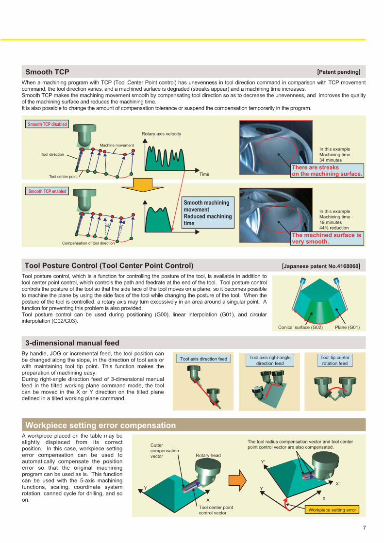
When a machining program with TCP (Tool Center Point control) has unevenness in tool direction command in comparison with TCP movement command, the tool direction varies, and a machined surface is degraded (streaks appear) and a machining time increases. Smooth TCP makes the machining movement smooth by compensating tool direction so as to decrease the unevenness, and improves the quality of the machining surface and reduces the machining time.It is also possible to change the amount of compensation tolerance or suspend the compensation temporarily in the program.
Smooth TCP [Patent pending]
Tool Posture Control (Tool Center Point Control) [Japanese patent No.4168060]
In this example
Machining time :
34 minutes
Tool center point
Tool direction
Machine movement
Compensation of tool direction
Cutter
compensation
vector Rotary head
Tool center point
control vector
X
Y
X
X'Y
Y'
There are streaks on the machining surface.
Smooth TCP disabled
Smooth TCP enabled
Smooth machining movement Reduced machining time
In this example
Machining time :
19 minutes
44% reduction
The machined surface isvery smooth.
Time
Rotary axis velocity
7
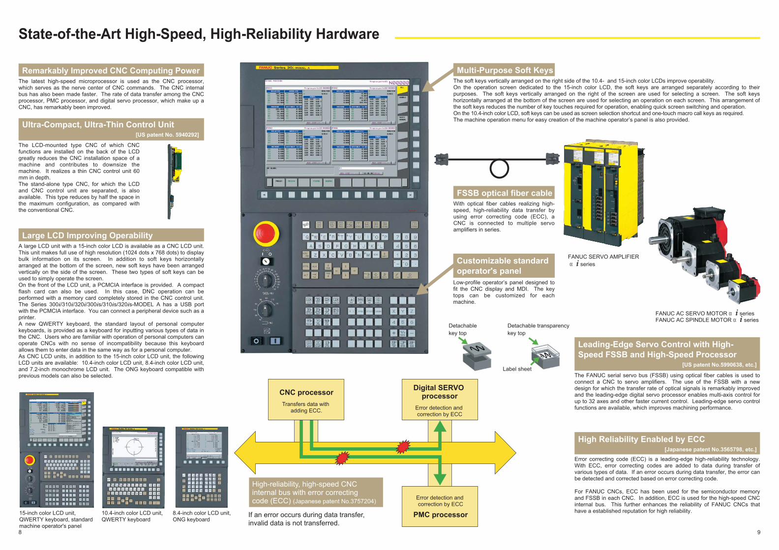
State-of-the-Art High-Speed, High-Reliability Hardware
Remarkably Improved CNC Computing PowerThe latest high-speed microprocessor is used as the CNC processor, which serves as the nerve center of CNC commands. The CNC internal bus has also been made faster. The rate of data transfer among the CNC processor, PMC processor, and digital servo processor, which make up a CNC, has remarkably been improved.
Leading-Edge Servo Control with High-
Speed FSSB and High-Speed Processor
The FANUC serial servo bus (FSSB) using optical fiber cables is used to connect a CNC to servo amplifiers. The use of the FSSB with a new design for which the transfer rate of optical signals is remarkably improved and the leading-edge digital servo processor enables multi-axis control for up to 32 axes and other faster current control. Leading-edge servo control functions are available, which improves machining performance.
High Reliability Enabled by ECC
[US patent No.5990638, etc.]
[Japanese patent No.3565798, etc.]
Error correcting code (ECC) is a leading-edge high-reliability technology. With ECC, error correcting codes are added to data during transfer of various types of data. If an error occurs during data transfer, the error can be detected and corrected based on error correcting code.
For FANUC CNCs, ECC has been used for the semiconductor memory and FSSB in each CNC. In addition, ECC is used for the high-speed CNC internal bus. This further enhances the reliability of FANUC CNCs that have a established reputation for high reliability.
FSSB optical fiber cableWith optical fiber cables realizing high-speed, high-reliability data transfer by using error correcting code (ECC), a CNC is connected to multiple servo amplifiers in series.
Large LCD Improving OperabilityA large LCD unit with a 15-inch color LCD is available as a CNC LCD unit. This unit makes full use of high resolution (1024 dots x 768 dots) to display bulk information on its screen. In addition to soft keys horizontally arranged at the bottom of the screen, new soft keys have been arranged vertically on the side of the screen. These two types of soft keys can be used to simply operate the screen.On the front of the LCD unit, a PCMCIA interface is provided. A compact flash card can also be used. In this case, DNC operation can be performed with a memory card completely stored in the CNC control unit. The Series 300i/310i/320i/300is/310is/320is-MODEL A has a USB port with the PCMCIA interface. You can connect a peripheral device such as a printer. A new QWERTY keyboard, the standard layout of personal computer keyboards, is provided as a keyboard for inputting various types of data in the CNC. Users who are familiar with operation of personal computers can operate CNCs with no sense of incompatibility because this keyboard allows them to enter data in the same way as for a personal computer. As CNC LCD units, in addition to the 15-inch color LCD unit, the following LCD units are available: 10.4-inch color LCD unit, 8.4-inch color LCD unit, and 7.2-inch monochrome LCD unit. The ONG keyboard compatible with previous models can also be selected.
Ultra-Compact, Ultra-Thin Control Unit
The LCD-mounted type CNC of which CNC functions are installed on the back of the LCD greatly reduces the CNC installation space of a machine and contributes to downsize the machine. It realizes a thin CNC control unit 60 mm in depth.The stand-alone type CNC, for which the LCD and CNC control unit are separated, is also available. This type reduces by half the space in the maximum configuration, as compared with the conventional CNC.
Customizable standard
operator's panel
Low-profile operator’s panel designed to fit the CNC display and MDI. The key tops can be customized for each machine.
15-inch color LCD unit, QWERTY keyboard, standard machine operator's panel
10.4-inch color LCD unit, QWERTY keyboard
8.4-inch color LCD unit, ONG keyboard
Detachable
key top
Detachable transparency
key top
Label sheet
[US patent No. 5940292]
Digital SERVO processor
Error detection and correction by ECC
CNC processor
Transfers data with adding ECC.
High-reliability, high-speed CNC internal bus with error correcting code (ECC) (Japanese patent No.3757204)
If an error occurs during data transfer,
invalid data is not transferred.
Error detection and correction by ECC
PMC processor
FANUC SERVO AMPLIFIER
αi series
FANUC AC SPINDLE MOTOR αi seriesFANUC AC SERVO MOTOR αi series
Multi-Purpose Soft KeysThe soft keys vertically arranged on the right side of the 10.4- and 15-inch color LCDs improve operability.On the operation screen dedicated to the 15-inch color LCD, the soft keys are arranged separately according to their purposes. The soft keys vertically arranged on the right of the screen are used for selecting a screen. The soft keys horizontally arranged at the bottom of the screen are used for selecting an operation on each screen. This arrangement of the soft keys reduces the number of key touches required for operation, enabling quick screen switching and operation.On the 10.4-inch color LCD, soft keys can be used as screen selection shortcut and one-touch macro call keys as required.The machine operation menu for easy creation of the machine operator’s panel is also provided.
8 9
FANUC SERVO
AMPLIFIER αi series
FANUC AC SPINDLE
MOTOR αi series
FANUC AC SERVO
MOTOR αi series
ナノ補間SERVO HRV Control
SPINDLE HRV Control
High-Speed, High-Quality Machining
High-Quality Machining Realized for All Types of Machining from Part
Machining to Complex Die Mold Machining
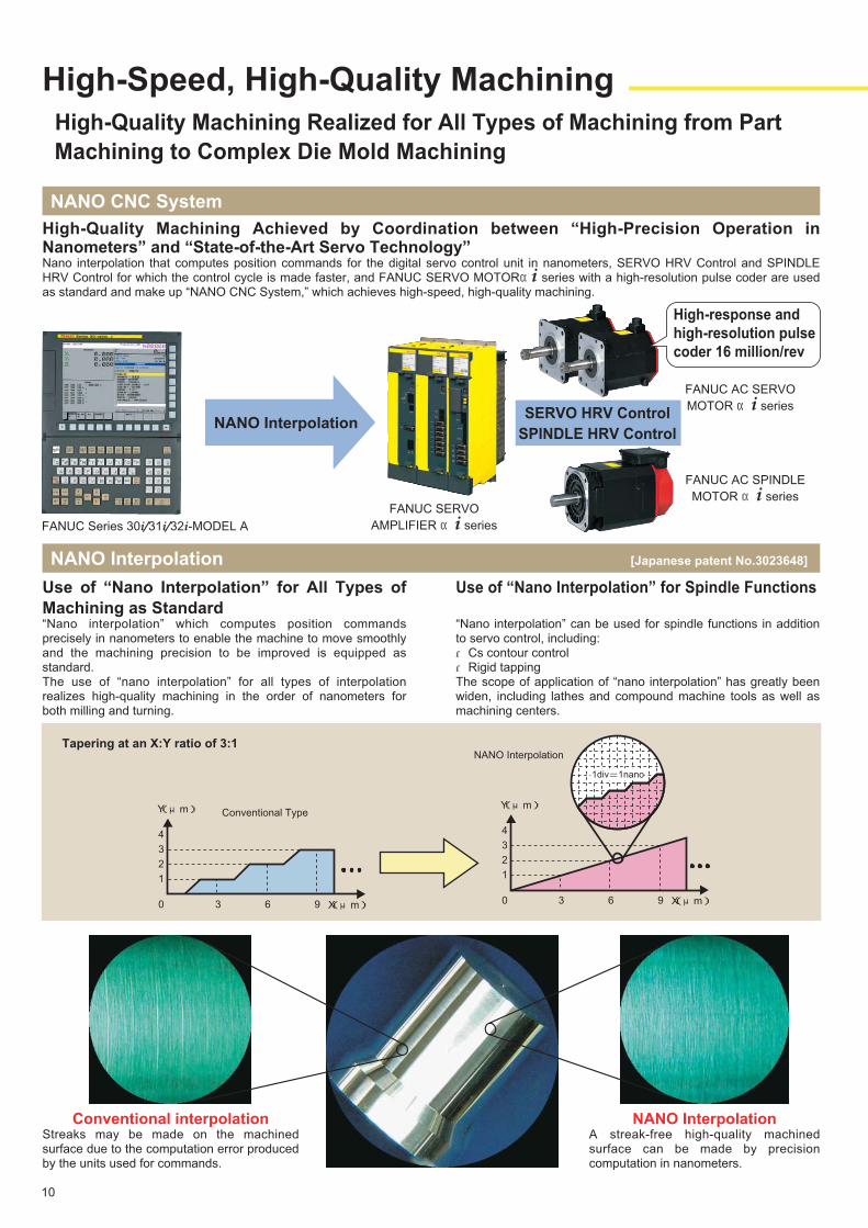
High-Quality Machining Achieved by Coordination between “High-Precision Operation in Nanometers” and “State-of-the-Art Servo Technology”Nano interpolation that computes position commands for the digital servo control unit in nanometers, SERVO HRV Control and SPINDLE HRV Control for which the control cycle is made faster, and FANUC SERVO MOTORαi series with a high-resolution pulse coder are used as standard and make up “NANO CNC System,” which achieves high-speed, high-quality machining.
NANO CNC System
Use of “Nano Interpolation” for All Types of
Machining as Standard“Nano interpolation” which computes position commands precisely in nanometers to enable the machine to move smoothly and the machining precision to be improved is equipped as standard.The use of “nano interpolation” for all types of interpolation realizes high-quality machining in the order of nanometers for both milling and turning.
Use of “Nano Interpolation” for Spindle Functions
“Nano interpolation” can be used for spindle functions in addition to servo control, including:・Cs contour control・Rigid tappingThe scope of application of “nano interpolation” has greatly been widen, including lathes and compound machine tools as well as machining centers.
NANO Interpolation [Japanese patent No.3023648]
FANUC Series 30i/31i/32i-MODEL A
NANO Interpolation
High-response and
high-resolution pulse
coder 16 million/rev
Conventional interpolationStreaks may be made on the machined surface due to the computation error produced by the units used for commands.
NANO InterpolationA streak-free high-quality machined surface can be made by precision computation in nanometers.
NANO Interpolation
1
0 3 6 9
2
3
4
Conventional TypeY(μm)
X(μm)
1
0 3 6 9
2
3
4
Y(μm)
X(μm)
1div=1nano
Tapering at an X:Y ratio of 3:1
10
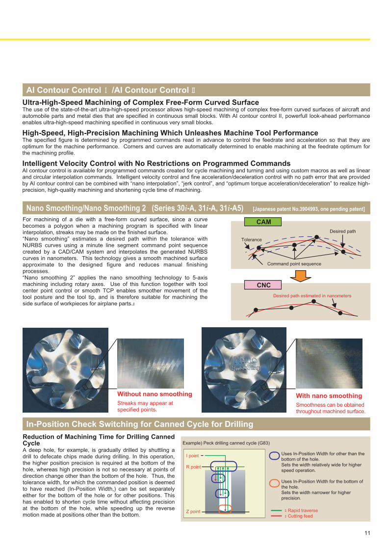
AI Contour Control Ⅰ/AI Contour Control Ⅱ
Ultra-High-Speed Machining of Complex Free-Form Curved SurfaceThe use of the state-of-the-art ultra-high-speed processor allows high-speed machining of complex free-form curved surfaces of aircraft and automobile parts and metal dies that are specified in continuous small blocks. With AI contour control II, powerfull look-ahead performance enables ultra-high-speed machining specified in continuous very small blocks.
High-Speed, High-Precision Machining Which Unleashes Machine Tool PerformanceThe specified figure is determined by programmed commands read in advance to control the feedrate and acceleration so that they are optimum for the machine performance. Corners and curves are automatically determined to enable machining at the feedrate optimum for the machining profile.
Intelligent Velocity Control with No Restrictions on Programmed CommandsAI contour control is available for programmed commands created for cycle machining and turning and using custom macros as well as linear and circular interpolation commands. Intelligent velocity control and fine acceleration/deceleration control with no path error that are provided by AI contour control can be combined with “nano interpolation”, “jerk control”, and “optimum torque acceleration/deceleration” to realize high-precision, high-quality machining and shortening cycle time of machining.
Without nano smoothing
Streaks may appear at specified points.
With nano smoothing
Smoothness can be obtained throughout machined surface.
In-Position Check Switching for Canned Cycle for Drilling
Reduction of Machining Time for Drilling Canned Cycle A deep hole, for example, is gradually drilled by shuttling a drill to defecate chips made during drilling. In this operation, the higher position precision is required at the bottom of the hole, whereas high precision is not so necessary at points of direction change other than the bottom of the hole. Thus, the tolerance width, for which the commanded position is deemed to have reached (In-Position Width,) can be set separately either for the bottom of the hole or for other positions. This has enabled to shorten cycle time without affecting precision at the bottom of the hole, while speeding up the reverse motion made at positions other than the bottom.
For machining of a die with a free-form curved surface, since a curve becomes a polygon when a machining program is specified with linear interpolation, streaks may be made on the finished surface. “Nano smoothing” estimates a desired path within the tolerance with NURBS curves using a minute line segment command point sequence created by a CAD/CAM system and interpolates the generated NURBS curves in nanometers. This technology gives a smooth machined surface approximate to the designed figure and reduces manual finishing processes. “Nano smoothing 2” applies the nano smoothing technology to 5-axis machining including rotary axes. Use of this function together with tool center point control or smooth TCP enables smoother movement of the tool posture and the tool tip, and is therefore suitable for machining the side surface of workpieces for airplane parts.
Nano Smoothing/Nano Smoothing 2 (Series 30i-A, 31i-A, 31i-A5) [Japanese patent No.3904993, one pending patent]
Desired path estimated in nanometers
Tolerance
Desired path
Command point sequence
CAM
CNC
Example) Peck drilling canned cycle (G83)
Uses In-Position Width for other than the
bottom of the hole.
Sets the width relatively wide for higher
speed operation.
Uses In-Position Width for the bottom of
the hole.
Sets the width narrower for higher
precision.
Z point :Rapid traverse
:Cutting feed
R point
I point
11
Servo Control Achieving High-Speed, High-Quality Machining
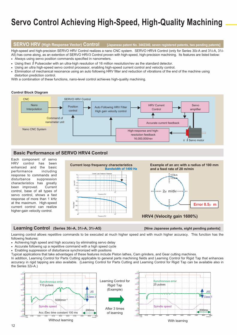
Each component of servo HRV control has been enhanced and the basic performance including response to commands and disturbance suppression characteristics has greatly been improved. Current control, base of all types of servo control, shows a fast response of more than 1 kHz at the maximum. High-speed current control can realize higher-gain velocity control.
Basic Performance of SERVO HRV4 Control
Learning control allows repetitive commands to be executed at much higher speed and with much higher accuracy. This function has the following features:● Achieving high speed and high accuracy by eliminating servo delay● Accurate following up a repetitive command with a high speed cycle● Enabling suppression of disturbance synchronized with positionsTypical applications that take advantages of these features include Piston lathes, Cam grinders, and Gear cutting machines.In addition, Learning Control for Parts Cutting applicable to general parts machining fields and Learning Control for Rigid Tap that enhances accuracy in rigid tapping are also available. (Learning Control for Parts Cutting and Learning Control for Rigid Tap can be available also in the Series 32i-A.)
Learning Control (Series 30i-A, 31i-A, 31i-A5) [Nine Japanese patents, eight pending patents]
SERVO HRV (High Response Vector) Control [Japanese patent No. 3442340, seven registered patents, two pending patents]
High-speed and high-precision SERVO HRV Control realizes a nano CNC system. SERVO HRV4 Control (only for Series 30i-A and 31i-A, 31i-A5) has come along, as an extention of SERVO HRV3 Control proven with high-speed, high-precision machining. Its features are listed below:● Always using servo position commands specified in nanometers.
● Using theαi Pulsecoder with an ultra-high resolution of 16 million resolution/rev as the standard detector.● Using an ultra high-speed servo control processor, enabling high-speed current control and velocity control.● Elimination of mechanical resonance using an auto following HRV filter and reduction of vibrations of the end of the machine using
distortion prediction control.With a combination of these functions, nano-level control achieves high-quality machining.
Current loop frequency characteristics Example of an arc with a radius of 100 mm and a feed rate of 20 m/min
Control Block Diagram
Bandwidth of 1400 Hz
HRV4 (Velocity gain 1600%)
2μm/div
Error 0.5μm
CNC SERVO HRV Control
Nano CNC System
Command of
nanometer unit
Nano
InterpolationPosition
control
Auto Following HRV Filter
High gain velocity control
HRV Current
Control
High-response and high-
resolution feedback
16,000,000/rev
Servo
amplifier
Accurate current feedback
αi Servo motor
Learning Control for
Rigid Tap
(Example)
After 3 times
of learning
Without learning
Synchronous error
110 pulses
Synchronous error
25 pulses
Spindle speed
Acc./Dec time constant 100 ms
5000min-1
With learning
200ms
JIS
Class 2
Spindle speed
200ms
JIS
Class 1
12
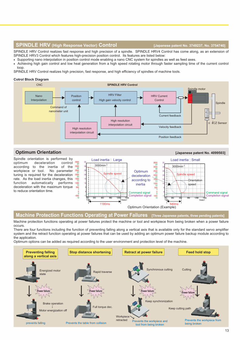
Spindle orientation is performed by optimum deceleration control according to the inertia of the workpiece or tool. No parameter tuning is required for the deceleration rate. As the load inertia changes, this function automatically performs deceleration with the maximum torque to reduce orientation time.
Optimum Orientation
SPINDLE HRV (High Response Vector) Control [Japanese patent No. 3749237, No. 3754740]
SPINDLE HRV Control realizes fast response and high precision of a spindle. SPINDLE HRV4 Control has come along, as an extension of SPINDLE HRV3 Control which features high-precision position control. Its features are listed below:● Supporting nano interpolation in position control mode enabling a nano CNC system for spindles as well as feed axes.● Achieving high gain control and low heat generation from a high speed rotating motor through faster sampling time of the current control
loop.SPINDLE HRV Control realizes high precision, fast response, and high efficiency of spindles of machine tools.
Machine Protection Functions Operating at Power Failures [Three Japanese patents, three pending patents]
Machine protection functions operating at power failures protect the machine or tool and workpiece from being broken when a power failure occurs.There are four functions including the function of preventing falling along a vertical axis that is available only for the standard servo amplifier system and the retract function operating at power failures that can be used by adding an optimum power failure backup module according to the application.Optimum options can be added as required according to the user environment and protection level of the machine.
Preventing fallingalong a vertical axis
Stop distance shortening Retract at power failure Feed hold stop
prevents falling Prevents the table from collisionPrevents the workpiece and
tool from being broken
αiCZ Sensor
CNC
Nano
Interpolation
Command of
nanometer unit
SPINDLE HRV Control
Position
control
High resolution
interpolation circuit
HRV Filter
High gain velocity control
High resolution
interpolation circuit
HRV Current
Control
Current feedback
Velocity feedback
Position feedback
Spindle motor
Spindle
Power failure↓
Cotrol Block Diagram
Rapid traverseEnergized motor
state
Synchronous cutting Cutting
Brake operation
↓Motor energization off
Full torque dec.
Power failure↓Keep synchronization
Workpiece
retracted
Power failure↓
↓ Prevents the workpiece from
being broken
Keep cutting path
Power failure↓
Optimum
deceleration
according to
inertia
1180ms
Load inertia : Large Load inertia : Small
Spindle speed
3000min-1
Command signalCompletion signal
540ms
Spindle speed
3000min-1
Orientation
speed
Command signalCompletion signal
Optimum Orientation (Example)
[Japanese patent No. 4099503]
13
Excellent Operation
Program Management that Becomes Easy to Use
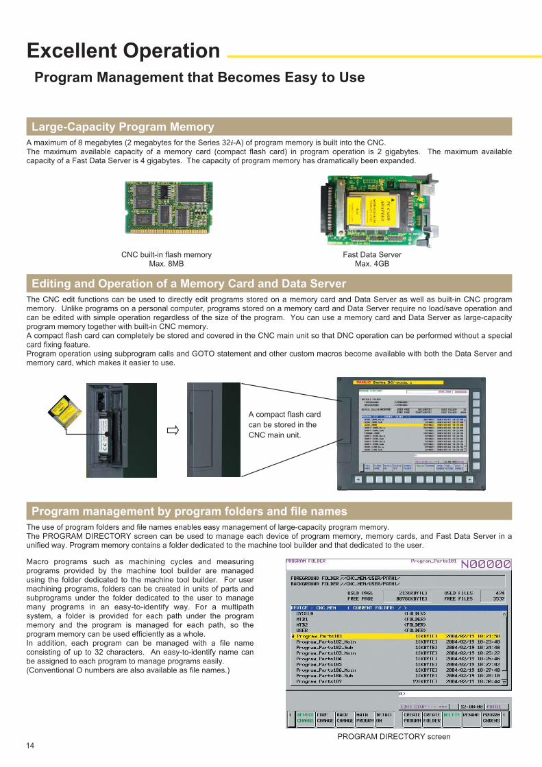
The CNC edit functions can be used to directly edit programs stored on a memory card and Data Server as well as built-in CNC program memory. Unlike programs on a personal computer, programs stored on a memory card and Data Server require no load/save operation and can be edited with simple operation regardless of the size of the program. You can use a memory card and Data Server as large-capacity program memory together with built-in CNC memory.A compact flash card can completely be stored and covered in the CNC main unit so that DNC operation can be performed without a special card fixing feature.Program operation using subprogram calls and GOTO statement and other custom macros become available with both the Data Server and memory card, which makes it easier to use.
Editing and Operation of a Memory Card and Data Server
A maximum of 8 megabytes (2 megabytes for the Series 32i-A) of program memory is built into the CNC.The maximum available capacity of a memory card (compact flash card) in program operation is 2 gigabytes. The maximum available capacity of a Fast Data Server is 4 gigabytes. The capacity of program memory has dramatically been expanded.
Large-Capacity Program Memory
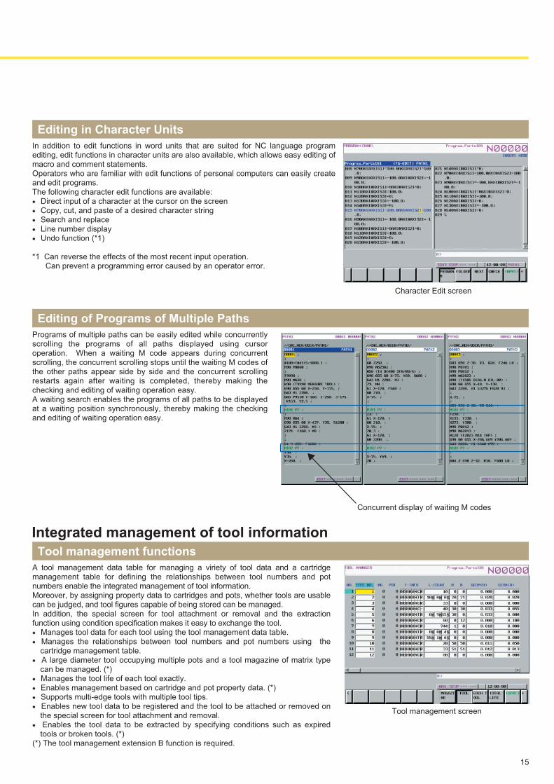
The use of program folders and file names enables easy management of large-capacity program memory.The PROGRAM DIRECTORY screen can be used to manage each device of program memory, memory cards, and Fast Data Server in a unified way. Program memory contains a folder dedicated to the machine tool builder and that dedicated to the user.
Program management by program folders and file names
14
Macro programs such as machining cycles and measuring programs provided by the machine tool builder are managed using the folder dedicated to the machine tool builder. For user machining programs, folders can be created in units of parts and subprograms under the folder dedicated to the user to manage many programs in an easy-to-identify way. For a multipath system, a folder is provided for each path under the program memory and the program is managed for each path, so the program memory can be used efficiently as a whole. In addition, each program can be managed with a file name consisting of up to 32 characters. An easy-to-identify name can be assigned to each program to manage programs easily.(Conventional O numbers are also available as file names.)
PROGRAM DIRECTORY screen
A compact flash card
can be stored in the
CNC main unit.
CNC built-in flash memoryMax. 8MB
Fast Data ServerMax. 4GB
15
In addition to edit functions in word units that are suited for NC language program editing, edit functions in character units are also available, which allows easy editing of macro and comment statements.Operators who are familiar with edit functions of personal computers can easily create and edit programs.The following character edit functions are available:● Direct input of a character at the cursor on the screen● Copy, cut, and paste of a desired character string● Search and replace● Line number display● Undo function (*1)
*1 Can reverse the effects of the most recent input operation.Can prevent a programming error caused by an operator error.
Editing in Character Units
Character Edit screen
A tool management data table for managing a viriety of tool data and a cartridge management table for defining the relationships between tool numbers and pot numbers enable the integrated management of tool information.Moreover, by assigning property data to cartridges and pots, whether tools are usable can be judged, and tool figures capable of being stored can be managed.In addition, the special screen for tool attachment or removal and the extraction function using condition specification makes it easy to exchange the tool.● Manages tool data for each tool using the tool management data table.● Manages the relationships between tool numbers and pot numbers using the
cartridge management table.● A large diameter tool occupying multiple pots and a tool magazine of matrix type
can be managed. (*) ● Manages the tool life of each tool exactly.● Enables management based on cartridge and pot property data. (*) ● Supports multi-edge tools with multiple tool tips.● Enables new tool data to be registered and the tool to be attached or removed on
the special screen for tool attachment and removal. ● Enables the tool data to be extracted by specifying conditions such as expired
tools or broken tools. (*)(*) The tool management extension B function is required.
Tool management functions
Integrated management of tool information
Tool management screen
Programs of multiple paths can be easily edited while concurrently scrolling the programs of all paths displayed using cursor operation. When a waiting M code appears during concurrent scrolling, the concurrent scrolling stops until the waiting M codes of the other paths appear side by side and the concurrent scrolling restarts again after waiting is completed, thereby making the checking and editing of waiting operation easy.A waiting search enables the programs of all paths to be displayed at a waiting position synchronously, thereby making the checking and editing of waiting operation easy.
Editing of Programs of Multiple Paths
Concurrent display of waiting M codes
Easy Operation
Operator-Friendly Display and Operation
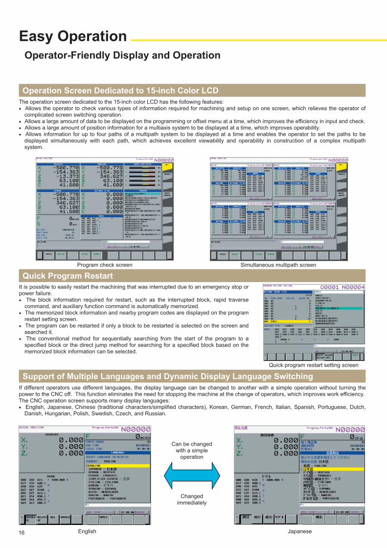
The operation screen dedicated to the 15-inch color LCD has the following features:● Allows the operator to check various types of information required for machining and setup on one screen, which relieves the operator of
complicated screen switching operation.● Allows a large amount of data to be displayed on the programming or offset menu at a time, which improves the efficiency in input and check.● Allows a large amount of position information for a multiaxis system to be displayed at a time, which improves operability.● Allows information for up to four paths of a multipath system to be displayed at a time and enables the operator to set the paths to be
displayed simultaneously with each path, which achieves excellent viewability and operability in construction of a complex multipath system.
Operation Screen Dedicated to 15-inch Color LCD
If different operators use different languages, the display language can be changed to another with a simple operation without turning the power to the CNC off. This function eliminates the need for stopping the machine at the change of operators, which improves work efficiency.The CNC operation screen supports many display languages:● English, Japanese, Chinese (traditional characters/simplified characters), Korean, German, French, Italian, Spanish, Portuguese, Dutch,
Danish, Hungarian, Polish, Swedish, Czech, and Russian.
Support of Multiple Languages and Dynamic Display Language Switching
Simultaneous multipath screenProgram check screen
Can be changedwith a simple
operation
Changedimmediately
JapaneseEnglish
It is possible to easily restart the machining that was interrupted due to an emergency stop or power failure.● The block information required for restart, such as the interrupted block, rapid traverse
command, and auxiliary function command is automatically memorized.● The memorized block information and nearby program codes are displayed on the program
restart setting screen.● The program can be restarted if only a block to be restarted is selected on the screen and
searched it.● The conventional method for sequentially searching from the start of the program to a
specified block or the direct jump method for searching for a specified block based on the memorized block information can be selected.
Quick Program Restart
Quick program restart setting screen
16
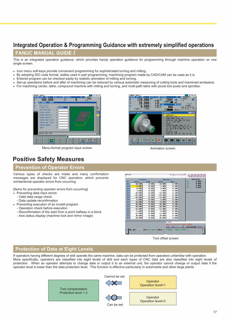
Various types of checks are made and many confirmation messages are displayed for CNC operation, which prevents unintentional operator errors from occurring. [Items for preventing operator errors from occurring]● Preventing data input errors - Valid data range check - Data update reconfirmation● Preventing execution of an invalid program - Operation check before execution - Reconfirmation of the start from a point halfway in a block - Axis status display (machine lock and mirror image)
Prevention of Operator Errors
If operators having different degrees of skill operate the same machine, data can be protected from operators unfamiliar with operation.More specifically, operators are classified into eight levels of skill and each types of CNC data are also classified into eight levels of protection. When an operator attempts to change data or output it to an external unit, the operator cannot change or output data if the operator level is lower than the data protection level. This function is effective particularly in automobile and other large plants.
Protection of Data at Eight Levels
Tool offset screen
Positive Safety Measures
OperatorOperation level=3
Tool compensationProtection level = 2
Cannot be set
Can be set
OperatorOperation level=1
This is an integrated operation guidance, which provides handy operation guidance for programming through machine operation on one single screen.
● Icon menu soft-keys provide convenient programming for sophisticated turning and milling.● By adopting ISO code format, widely used in part programming, machining program made by CAD/CAM can be used as it is.● Entered program can be checked easily by realistic animation of milling and turning.● Set-up operations before and after of machining can be reduced by various automatic measuring of cutting tools and machined workpiece.● For machining center, lathe, compound machine with milling and turning, and multi-path lathe with plural tool posts and spindles.
FANUC MANUAL GUIDE i
Animation screenMenu-format program input screen
Integrated Operation & Programming Guidance with extremely simplified operations
17
Network Support Functions
With plenty of network functions, you can construct an optimum system for a CNC machine tool.
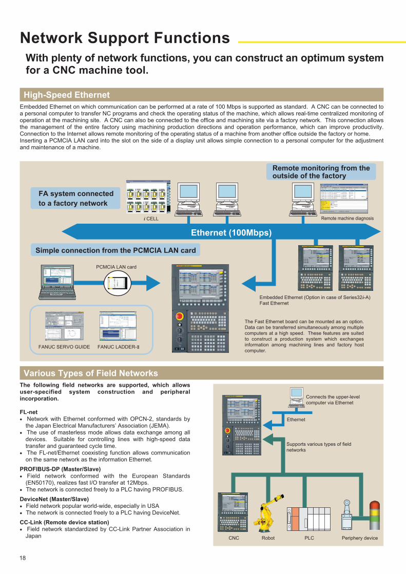
Embedded Ethernet on which communication can be performed at a rate of 100 Mbps is supported as standard. A CNC can be connected to a personal computer to transfer NC programs and check the operating status of the machine, which allows real-time centralized monitoring of operation at the machining site. A CNC can also be connected to the office and machining site via a factory network. This connection allows the management of the entire factory using machining production directions and operation performance, which can improve productivity. Connection to the Internet allows remote monitoring of the operating status of a machine from another office outside the factory or home.Inserting a PCMCIA LAN card into the slot on the side of a display unit allows simple connection to a personal computer for the adjustment and maintenance of a machine.
High-Speed Ethernet
The following field networks are supported, which allows user-specified system construction and peripheral incorporation.
FL-net ● Network with Ethernet conformed with OPCN-2, standards by
the Japan Electrical Manufacturers’ Association (JEMA).● The use of masterless mode allows data exchange among all
devices. Suitable for controlling lines with high-speed data transfer and guaranteed cycle time.
● The FL-net/Ethernet coexisting function allows communication on the same network as the information Ethernet.
PROFIBUS-DP (Master/Slave)● Field network conformed with the European Standards
(EN50170), realizes fast I/O transfer at 12Mbps.● The network is connected freely to a PLC having PROFIBUS.
DeviceNet (Master/Slave) ● Field network popular world-wide, especially in USA● The network is connected freely to a PLC having DeviceNet.
CC-Link (Remote device station)● Field network standardized by CC-Link Partner Association in
Japan
Various Types of Field Networks
FA system connected
to a factory network
i CELL
Remote monitoring from theoutside of the factory
Remote machine diagnosis
Ethernet (100Mbps)
Simple connection from the PCMCIA LAN card
PCMCIA LAN card
FANUC SERVO GUIDE FANUC LADDER-Ⅲ
Embedded Ethernet (Option in case of Series32i-A)
Fast Ethernet
Periphery device
Connects the upper-level
computer via Ethernet
Supports various types of field
networks
CNC Robot PLC
Ethernet
The Fast Ethernet board can be mounted as an option.
Data can be transferred simultaneously among multiple
computers at a high speed. These features are suited
to construct a production system which exchanges
information among machining lines and factory host
computer.
18
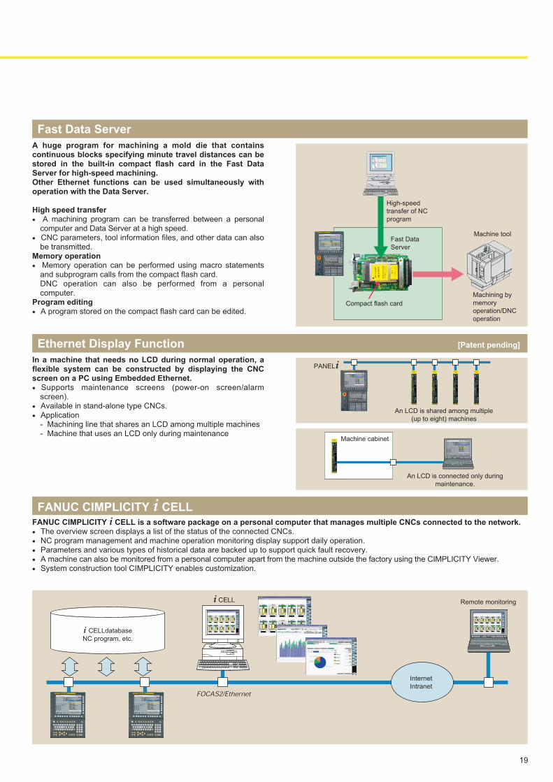
Remote monitoring
FANUC CIMPLICITY i CELL is a software package on a personal computer that manages multiple CNCs connected to the network.● The overview screen displays a list of the status of the connected CNCs.● NC program management and machine operation monitoring display support daily operation.● Parameters and various types of historical data are backed up to support quick fault recovery.● A machine can also be monitored from a personal computer apart from the machine outside the factory using the CIMPLICITY Viewer.● System construction tool CIMPLICITY enables customization.
FANUC CIMPLICITY i CELL
A huge program for machining a mold die that contains continuous blocks specifying minute travel distances can be stored in the built-in compact flash card in the Fast Data Server for high-speed machining. Other Ethernet functions can be used simultaneously with operation with the Data Server.
High speed transfer● A machining program can be transferred between a personal
computer and Data Server at a high speed.● CNC parameters, tool information files, and other data can also
be transmitted.Memory operation● Memory operation can be performed using macro statements
and subprogram calls from the compact flash card.DNC operation can also be performed from a personal computer.
Program editing● A program stored on the compact flash card can be edited.
Fast Data Server
i CELLdatabase
NC program, etc.
FOCAS2/Ethernet
Internet
Intranet
High-speed
transfer of NC
program
Machining by
memory
operation/DNC
operation
Fast Data
Server
Compact flash card
Machine tool
In a machine that needs no LCD during normal operation, a flexible system can be constructed by displaying the CNC screen on a PC using Embedded Ethernet. ● Supports maintenance screens (power-on screen/alarm
screen).● Available in stand-alone type CNCs.● Application
- Machining line that shares an LCD among multiple machines - Machine that uses an LCD only during maintenance
Ethernet Display Function [Patent pending]
Machine cabinet
An LCD is shared among multiple
(up to eight) machines
An LCD is connected only during
maintenance.
PANELi
i CELL
19
Easy Maintenance
In case of a fault, quick solution of the problem is supported
SERVO GUIDE is a tuning software product operating on a personal computer that comprehensively handles operations required for servo and spindle tuning, such as creation of test programs, parameter setting, and data measurement. It has the function for measuring the acceleration/deceleration characteristics and frequency response of a spindle as well as the function for automatically tuning gain, filter, and quadrant protrusion compensation, thereby allowing machine tool builders to optimize parameters in a short time.
FANUC SERVO GUIDE
This function displays the following servo-related data on the CNC display to provide means of analysis:- Time axis display - Geometric error display- Path display - Frequency analysis displayMachine tool builders can use this function for inspection before shipment.
SERVO GUIDE Mate
20
Various types of data including parameters and offsets that are stored in battery-backed SRAM are saved in the built-in flash memory which is not erased when the power is turned off, at power-on.If the battery is exhausted and data is erased, easy data recovery is allowed.
Automatic Data Backup
The update history of tool compensation, work coordinate system compensation, and custom macro common variables can be recorded. In addition, when an alarm occurs, detailed modal information, absolute coordinates, and machine coordinates as well as the alarm number and message can be recorded. The information helps you identify the cause when an alarm occurs.
Operating history, alarm history
● Since detailed information on the generated alarm is displayed, the cause and method of clearing the alarm can be obtained.
● The operating method is displayed for each operational item. ● The parameter number list is displayed for each function.
Help Function
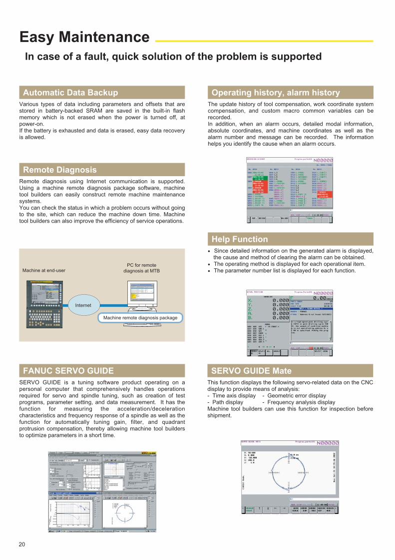
Remote diagnosis using Internet communication is supported. Using a machine remote diagnosis package software, machine tool builders can easily construct remote machine maintenance systems.You can check the status in which a problem occurs without going to the site, which can reduce the machine down time. Machine tool builders can also improve the efficiency of service operations.
Remote Diagnosis
Internet
Machine at end-userPC for remote
diagnosis at MTB
Machine remote diagnosis package
21
A PMC, which consists of a dedicated processor and custom LSI, processes large sequence control at a high speed.One PMC can execute up to three independent ladder programs. Each ladder program has an independent data area, which enables programs to be developed as independent modules.Ladder programs for loader and peripheral control can be created added and modified separately. Ladder programs can easily be developed and the machine can easily be systematized according to each user's machine configuration. External PLC or other devices for peripheral control become unnecessary, which reduces system costs.
Extended PMC Ladder Instruction function● The enhanced computation instructions enable to program
complex sequence control of machine into a simple ladder circuit with high readability.
● The new function helps reduce redundant descriptions of relay contacts and coils, thereby reducing the number of nets and steps of ladder program.
● The enhanced PMC function enables to correspond flexibly to an abundant array of machine sequence control requirements and realizes efficient ladder development and maintenance by machine tool builders.
Function Block function● This function enables to call up repeatedly used ladder circuit
patterns in blocks. ● By combining multiple Function Blocks, machine tool builders
can create complex ladder programs more efficiently, as if assembling components, with fewer steps for ladder program development and fewer ladder diagram drawings for maintenance.
High-Speed, Large-Capacity, and Multi-path PMC [Japanese patent No. 3896076, US patent No. 6999842]
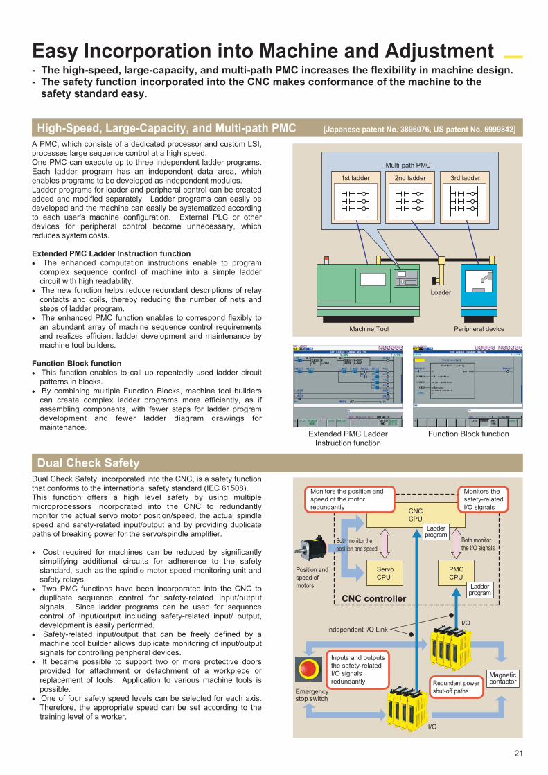
Dual Check Safety, incorporated into the CNC, is a safety function that conforms to the international safety standard (IEC 61508).This function offers a high level safety by using multiple microprocessors incorporated into the CNC to redundantly monitor the actual servo motor position/speed, the actual spindle speed and safety-related input/output and by providing duplicate paths of breaking power for the servo/spindle amplifier.
● Cost required for machines can be reduced by significantly simplifying additional circuits for adherence to the safety standard, such as the spindle motor speed monitoring unit and safety relays.
● Two PMC functions have been incorporated into the CNC to duplicate sequence control for safety-related input/output signals. Since ladder programs can be used for sequence control of input/output including safety-related input/ output, development is easily performed.
● Safety-related input/output that can be freely defined by a machine tool builder allows duplicate monitoring of input/output signals for controlling peripheral devices.
● It became possible to support two or more protective doors provided for attachment or detachment of a workpiece or replacement of tools. Application to various machine tools is possible.
● One of four safety speed levels can be selected for each axis. Therefore, the appropriate speed can be set according to the training level of a worker.
Dual Check Safety
Easy Incorporation into Machine and Adjustment- The high-speed, large-capacity, and multi-path PMC increases the flexibility in machine design. - The safety function incorporated into the CNC makes conformance of the machine to the
safety standard easy.
Peripheral device
Multi-path PMC
1st ladder 2nd ladder 3rd ladder
Loader
Machine Tool
Magnetic contactor
Monitors the position and
speed of the motor
redundantly
Monitors the
safety-related
I/O signals
Position and
speed of
motors
CNC
CPU
Both monitor the
position and speed
Servo
CPU
CNC controller
PMC
CPU
Both monitor
the I/O signals
Independent I/O Link
Emergencystop switch
Inputs and outputs
the safety-related
I/O signals
redundantly Redundant power
shut-off paths
I/O
I/O
Ladderprogram
Ladderprogram
Extended PMC LadderInstruction function
Function Block function
Plenty of Customize Functions
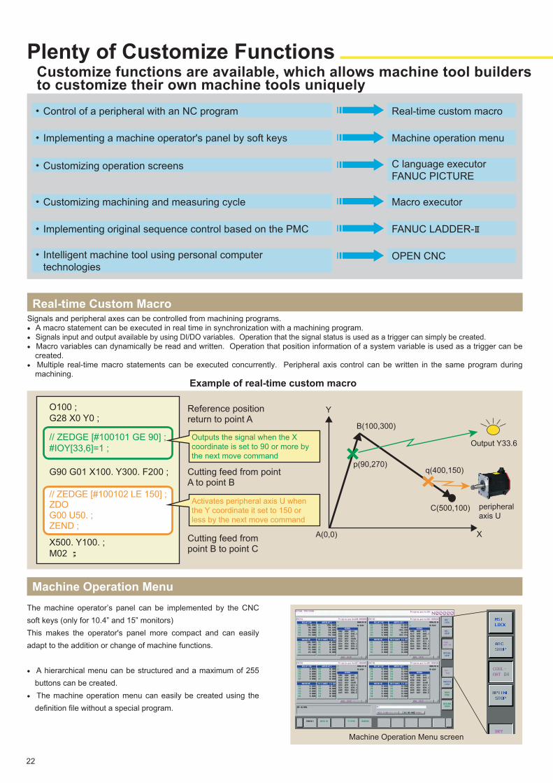
Signals and peripheral axes can be controlled from machining programs.● A macro statement can be executed in real time in synchronization with a machining program.● Signals input and output available by using DI/DO variables. Operation that the signal status is used as a trigger can simply be created.● Macro variables can dynamically be read and written. Operation that position information of a system variable is used as a trigger can be
created.● Multiple real-time macro statements can be executed concurrently. Peripheral axis control can be written in the same program during
machining.
Real-time Custom Macro
22
Example of real-time custom macro
X
O100 ;
G28 X0 Y0 ;
// ZEDGE [#100101 GE 90] ;
#IOY[33,6]=1 ;
G90 G01 X100. Y300. F200 ;
// ZEDGE [#100102 LE 150] ;ZDO G00 U50. ;ZEND ;
X500. Y100. ;
M02 ;
Reference positionreturn to point A
Outputs the signal when the X
coordinate is set to 90 or more by
the next move command
Cutting feed from pointA to point B
Activates peripheral axis U when
the Y coordinate it set to 150 or
less by the next move command
Cutting feed frompoint B to point C
Y
A(0,0)
B(100,300)
p(90,270)q(400,150)
C(500,100)
Output Y33.6
peripheral
axis U
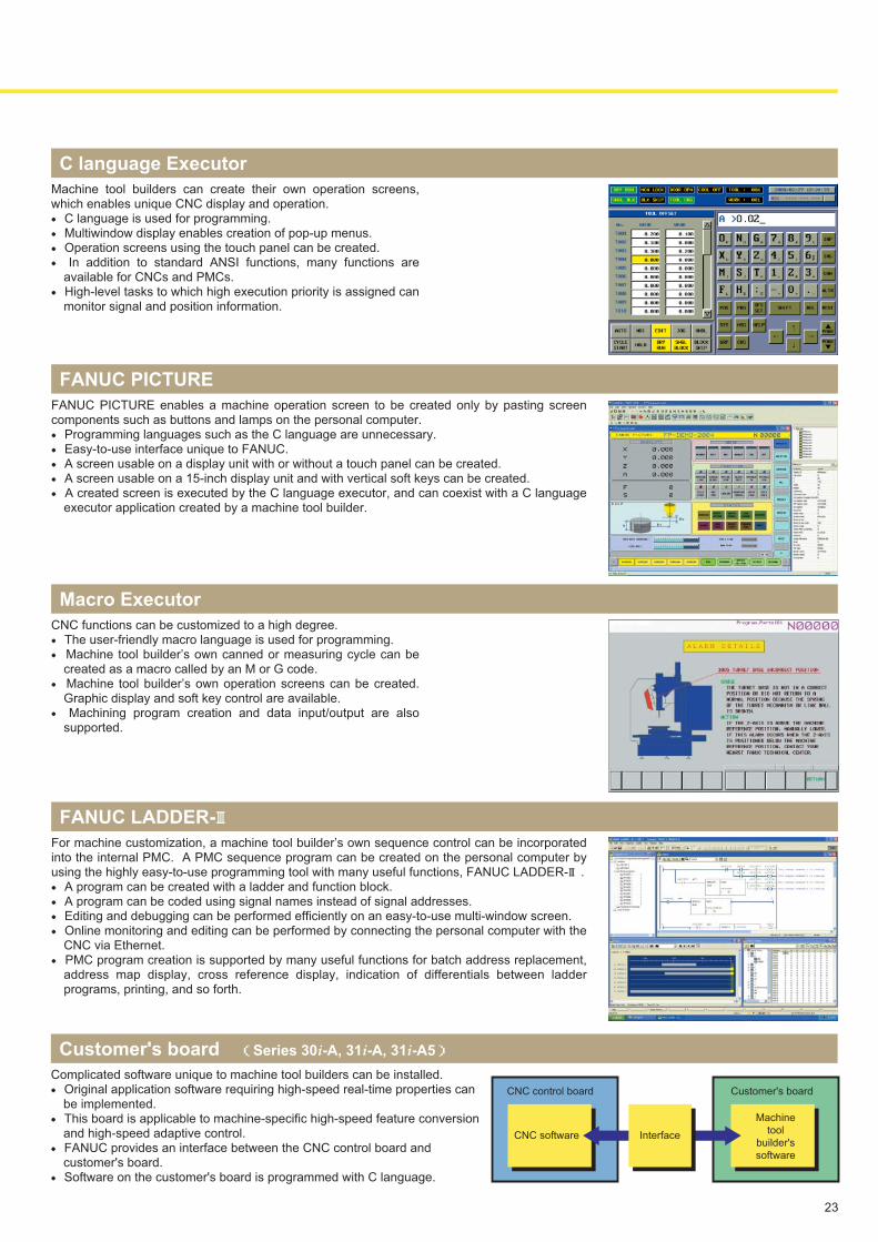
The machine operator’s panel can be implemented by the CNC
soft keys (only for 10.4” and 15” monitors)
This makes the operator's panel more compact and can easily
adapt to the addition or change of machine functions.
● A hierarchical menu can be structured and a maximum of 255
buttons can be created.
● The machine operation menu can easily be created using the
definition file without a special program.
Machine Operation Menu
Machine Operation Menu screen
OPEN CNC
・Control of a peripheral with an NC program
・Implementing a machine operator's panel by soft keys
・Customizing operation screens
・Customizing machining and measuring cycle
・Intelligent machine tool using personal computer
technologies
Real-time custom macro
Machine operation menu
C language executor
FANUC PICTURE
Macro executor
・Implementing original sequence control based on the PMC FANUC LADDER-Ⅲ
3
Customize functions are available, which allows machine tool builders to customize their own machine tools uniquely
23
Machine tool builders can create their own operation screens, which enables unique CNC display and operation.● C language is used for programming.● Multiwindow display enables creation of pop-up menus.● Operation screens using the touch panel can be created.● In addition to standard ANSI functions, many functions are
available for CNCs and PMCs.● High-level tasks to which high execution priority is assigned can
monitor signal and position information.
C language Executor
CNC functions can be customized to a high degree.● The user-friendly macro language is used for programming.● Machine tool builder’s own canned or measuring cycle can be
created as a macro called by an M or G code.● Machine tool builder’s own operation screens can be created.
Graphic display and soft key control are available.● Machining program creation and data input/output are also
supported.
Macro Executor
Complicated software unique to machine tool builders can be installed.● Original application software requiring high-speed real-time properties can
be implemented.● This board is applicable to machine-specific high-speed feature conversion
and high-speed adaptive control.● FANUC provides an interface between the CNC control board and
customer's board. ● Software on the customer's board is programmed with C language.
Customer's board (Series 30i-A, 31i-A, 31i-A5)
CNC software
Machine
tool
builder's
software
CNC control board Customer's board
Interface
FANUC PICTURE enables a machine operation screen to be created only by pasting screen components such as buttons and lamps on the personal computer.● Programming languages such as the C language are unnecessary.● Easy-to-use interface unique to FANUC.● A screen usable on a display unit with or without a touch panel can be created.● A screen usable on a 15-inch display unit and with vertical soft keys can be created.● A created screen is executed by the C language executor, and can coexist with a C language
executor application created by a machine tool builder.
FANUC PICTURE
For machine customization, a machine tool builder’s own sequence control can be incorporated into the internal PMC. A PMC sequence program can be created on the personal computer by using the highly easy-to-use programming tool with many useful functions, FANUC LADDER-Ⅲ.● A program can be created with a ladder and function block.● A program can be coded using signal names instead of signal addresses.● Editing and debugging can be performed efficiently on an easy-to-use multi-window screen.● Online monitoring and editing can be performed by connecting the personal computer with the
CNC via Ethernet.● PMC program creation is supported by many useful functions for batch address replacement,
address map display, cross reference display, indication of differentials between ladder programs, printing, and so forth.
FANUC LADDER-Ⅲ
Powerful Software Tools
Development by machine tool builders is supported in a variety of fields such as simulation, customization, and data management.
Software tools for CNC operation simulation on the personal computer are provided to fully utilize the ever advancing CNC functions.Two types of packages are available to meet applications:
● For CNC operation training FANUC NCGuide
● For application software development FANUC NCGuidePro
Simulation Tools Supporting Utilization of High-Level CNC Functions
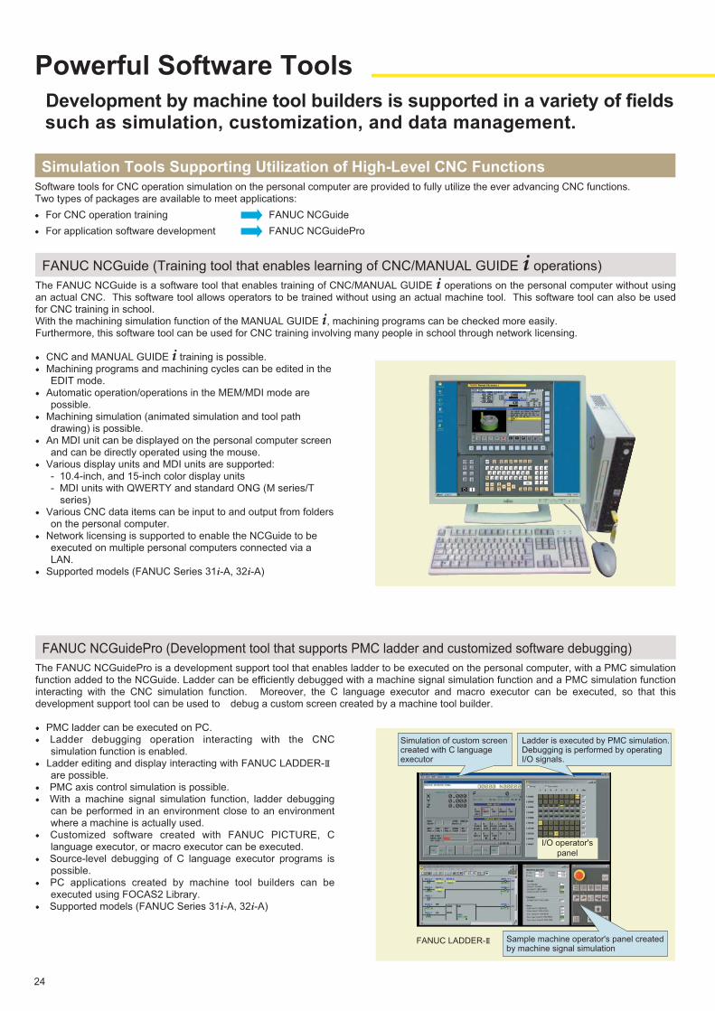
The FANUC NCGuide is a software tool that enables training of CNC/MANUAL GUIDE i operations on the personal computer without using an actual CNC. This software tool allows operators to be trained without using an actual machine tool. This software tool can also be used for CNC training in school.With the machining simulation function of the MANUAL GUIDE i, machining programs can be checked more easily.Furthermore, this software tool can be used for CNC training involving many people in school through network licensing.
● CNC and MANUAL GUIDE i training is possible.● Machining programs and machining cycles can be edited in the
EDIT mode.● Automatic operation/operations in the MEM/MDI mode are
possible.● Machining simulation (animated simulation and tool path
drawing) is possible.● An MDI unit can be displayed on the personal computer screen
and can be directly operated using the mouse.● Various display units and MDI units are supported:
- 10.4-inch, and 15-inch color display units - MDI units with QWERTY and standard ONG (M series/T
series)● Various CNC data items can be input to and output from folders
on the personal computer.● Network licensing is supported to enable the NCGuide to be
executed on multiple personal computers connected via a LAN.
● Supported models (FANUC Series 31i-A, 32i-A)
FANUC NCGuide (Training tool that enables learning of CNC/MANUAL GUIDE i operations)
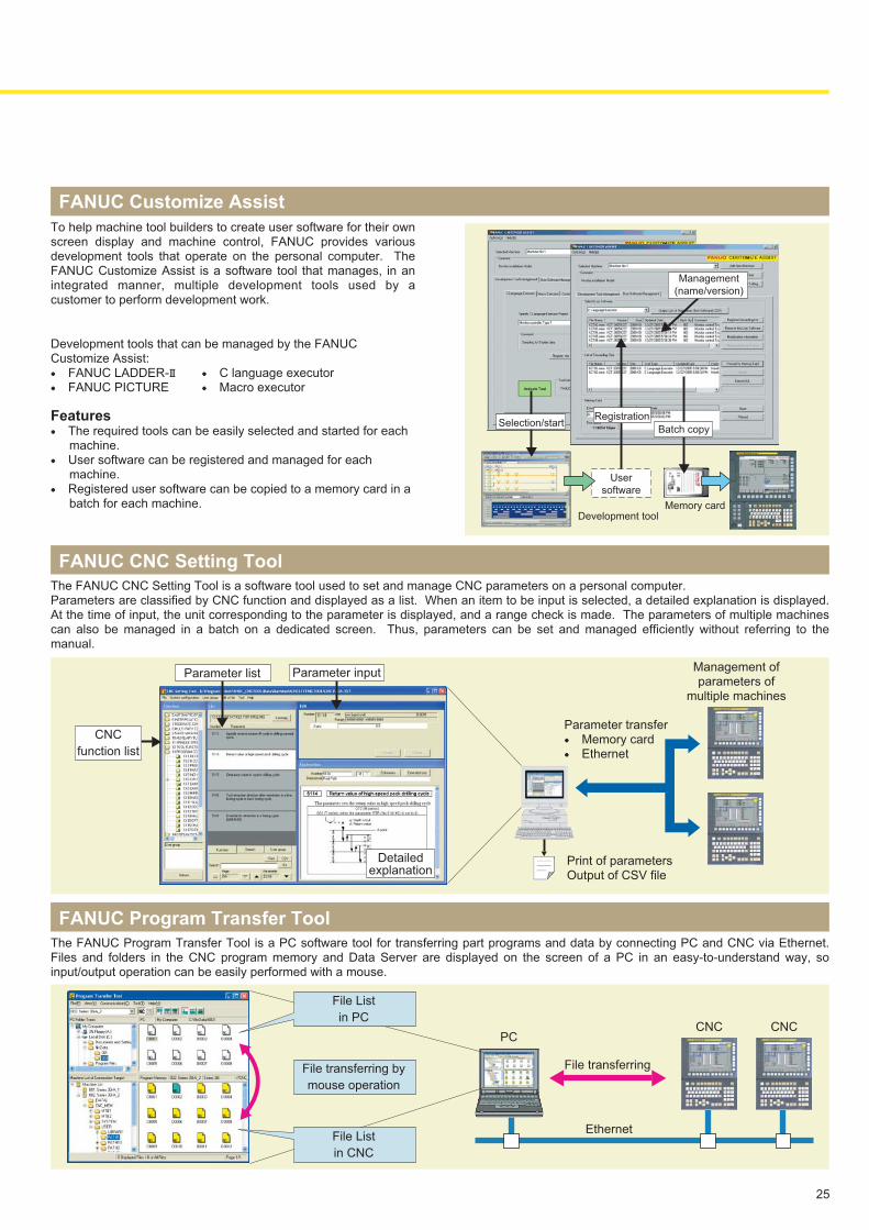
The FANUC NCGuidePro is a development support tool that enables ladder to be executed on the personal computer, with a PMC simulation function added to the NCGuide. Ladder can be efficiently debugged with a machine signal simulation function and a PMC simulation function interacting with the CNC simulation function. Moreover, the C language executor and macro executor can be executed, so that this development support tool can be used to debug a custom screen created by a machine tool builder.
● PMC ladder can be executed on PC.● Ladder debugging operation interacting with the CNC
simulation function is enabled.● Ladder editing and display interacting with FANUC LADDER-Ⅲ
are possible.● PMC axis control simulation is possible.● With a machine signal simulation function, ladder debugging
can be performed in an environment close to an environment where a machine is actually used.
● Customized software created with FANUC PICTURE, C language executor, or macro executor can be executed.
● Source-level debugging of C language executor programs is possible.
● PC applications created by machine tool builders can be executed using FOCAS2 Library.
● Supported models (FANUC Series 31i-A, 32i-A)
FANUC NCGuidePro (Development tool that supports PMC ladder and customized software debugging)
Simulation of custom screen created with C language executor
Ladder is executed by PMC simulation. Debugging is performed by operating I/O signals.
Sample machine operator's panel created by machine signal simulation
FANUC LADDER-Ⅲ
I/O operator's
panel
24
To help machine tool builders to create user software for their own screen display and machine control, FANUC provides various development tools that operate on the personal computer. The FANUC Customize Assist is a software tool that manages, in an integrated manner, multiple development tools used by a customer to perform development work.
Development tools that can be managed by the FANUC Customize Assist:● FANUC LADDER-Ⅲ ● C language executor● FANUC PICTURE ● Macro executor
Features● The required tools can be easily selected and started for each
machine.● User software can be registered and managed for each
machine.● Registered user software can be copied to a memory card in a
batch for each machine.
FANUC Customize Assist
The FANUC CNC Setting Tool is a software tool used to set and manage CNC parameters on a personal computer.Parameters are classified by CNC function and displayed as a list. When an item to be input is selected, a detailed explanation is displayed. At the time of input, the unit corresponding to the parameter is displayed, and a range check is made. The parameters of multiple machines can also be managed in a batch on a dedicated screen. Thus, parameters can be set and managed efficiently without referring to the manual.
FANUC CNC Setting Tool
Selection/startBatch copy
Management
(name/version)
Registration
User
software
Development toolMemory card
Detailedexplanation
Parameter input
Parameter transfer● Memory card● Ethernet
Management ofparameters of
multiple machines
Print of parametersOutput of CSV file
Parameter list
CNC
function list
Ethernet
File transferring
The FANUC Program Transfer Tool is a PC software tool for transferring part programs and data by connecting PC and CNC via Ethernet. Files and folders in the CNC program memory and Data Server are displayed on the screen of a PC in an easy-to-understand way, so input/output operation can be easily performed with a mouse.
FANUC Program Transfer Tool
CNCCNCPC
File List
in CNC
File transferring by
mouse operation
File List
in PC
25
Open CNCs compatible with Windows® OS
Optimum Combination of CNC and Personal Computer
26
Exhibiting Ability in Making Machine Tools Intelligent
FANUC OPEN CNCs realize the best combination between a CNC and personal computer by transferring bulk data via an original high-speed interface between the CNC and personal computer. FANUC OPEN CNC supports unique dedicated applications to fit their machine tools for machine tool builders to meet special needs for machine tool customers.FANUC OPEN CNC enables dedicated operation with GUI (graphical user interface) of CNC machine tool, communication of bulk information through network, tool life management with data base, and so on. FANUC OPEN CNC brings huge potentials through up-to-date computer and information technology for intelligent machine tools.
High-performance OPEN CNC with Windows® XPFANUC Series 300i/310i/320i - MODEL A
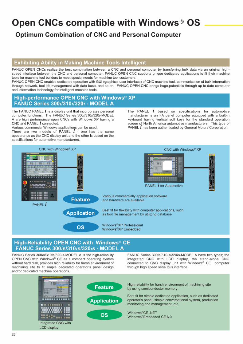
The FANUC PANEL i is a display unit that incorporates personal computer functions. The FANUC Series 300i/310i/320i-MODEL A are high performance open CNCs with Windows XP having a CNC and PANEL i connected.Various commercial Windows applications can be used.There are two models of PANEL i : one has the same appearance as the CNC display unit and the other is based on the specifications for automotive manufacturers.
High-Reliability OPEN CNC with Windows® CE FANUC Series 300is/310is/320is - MODEL A
FANUC Series 300is/310is/320is-MODEL A is the high-reliability OPEN CNC with Windows® CE as a compact operating system without hard disk, provides high reliability for harsh environment of machining site to fit simple dedicated operator’s panel design and/or dedicated machine operations.
FANUC Series 300is/310is/320is-MODEL A have two types; the integrated CNC with LCD display, the stand-alone CNC connected to CNC display unit with Windows® CE computer through high speed serial bus interface.
Various commercially application software and hardware are available
Best fit for flexibility with computer applications, such as tool file management by utilizing database
FeatureHigh reliability for harsh environment of machining site by using semiconductor memory
Best fit for simple dedicated application, such as dedicated operator’s panel, simple conversational system, production monitoring and management, etc.
Application
OS
Feature
Application
OS
CNC with Windows® XP
PANEL i
CNC with Windows® XP
PANEL i for Automotive
Integrated CNC with
LCD display
The PANEL i based on specifications for automotive manufacturer is an FA panel computer equipped with a built-in keyboard having vertical soft keys for the standard operation screen of North America automotive manufacturers. This type of PANEL i has been authenticated by General Motors Corporation.
Windows®XP ProfessionalWindows®XP Embedded
Windows®CE .NETWindows®Embedded CE 6.0
27
FOCAS2 Library
FOCAS2 Driver and Library are provided to handle the data of CNC/PMC.The users can make their own applications using FOCAS2 Library. For FOCAS2, plenty of easy-to-use functions are available for creating screens.
FOCAS2 : FANUC Open CNC API Specifications version 2
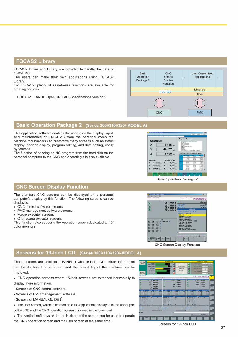
Basic Operation Package 2 (Series 300i/310i/320i-MODEL A)
This application software enables the user to do the display, input, and maintenance of CNC/PMC from the personal computer. Machine tool builders can customize many screens such as status display, position display, program editing, and data setting, easily by yourself.The function of sending an NC program from the hard disk on the personal computer to the CNC and operating it is also available.
CNC Screen Display Function
The standard CNC screens can be displayed on a personal computer’s display by this function. The following screens can be displayed.● CNC control software screens● PMC management software screens● Macro executor screens● C language executor screensThis function also supports the operation screen dedicated to 15” color monitors.
Basic Operation Package 2
CNC Screen Display Function
CNC PMC
FOCAS2Libraries
Driver
Basic
Operation
Package 2
CNC
Screen
Display
Function
User Customized
applications… …
Screens for 19-Inch LCD (Series 300i/310i/320i-MODEL A)
These screens are used for a PANEL i with 19-inch LCD. Much information
can be displayed on a screen and the operability of the machine can be
improved.
● CNC operation screens where 15-inch screens are extended horizontally to
display more information.
- Screens of CNC control software
- Screens of PMC management software
- Screens of MANUAL GUIDE i
● The user screen, which is created as a PC application, displayed in the upper part
of the LCD and the CNC operation screen displayed in the lower part
● The vertical soft keys on the both sides of the screen can be used to operate
the CNC operation screen and the user screen at the same time.Screens for 19-Inch LCD
● All specifications are subject to change without notice.
● No part of this catalog may be reproduced in any form.
● The products in this catalog are controlled based on Japan's "Foreign Exchange and Foreign Trade Law". The export of Series 30i/300i/300is-A
and 31i/310i/310is-A5 from Japan is subject to an export License by the government of Japan. Other models in this catalog may also be subject
to export controls.
Further, re-export to another country may be subject to the license of the government of the country from where the product is re-exported.
Furthermore, the product may also be controlled by re-export regulations of the United States government.
Should you wish to export or re-export these products, please contact FANUC for advice. F30i-A(E)-05, 2008.10, Printed in Japan
20032003
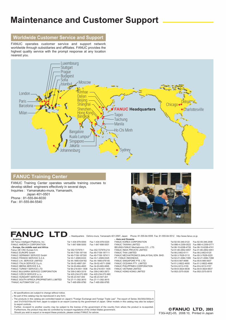
Worldwide Customer Service and Support
FANUC operates customer service and support network worldwide through subsidiaries and affiliates. FANUC provides the highest quality service with the prompt response at any location nearest you.
Maintenance and Customer Support
Charlottesville
DetroitChicago
KimhaeDalianBeijing
London
ParisBarcelona
Luxembourg
PragueStuttgart
Istanbul MoscowSofia
Milan
Shanghai
Hong KongShenzhen
Bangkok
BangaloreKuala LumpurSingaporeJakarta
Johannesburg
Ho Chi MinhManila
Sydney
TaipeiTaichung
FANUC Headquarters
Budapest
FANUC Training Center
FANUC Training Center operates versatile training courses to develop skilled engineers effectively in several days.Inquiries : Yamanakako-mura, Yamanashi, Japan 401-0501Phone : 81-555-84-6030Fax : 81-555-84-5540
● America
GE Fanuc Intelligent Platforms, Inc. Tel 1-434-978-5000 Fax 1-434-978-5320
FANUC AMERICA CORPORATION Tel 1-847-898-5000 Fax 1-847-898-5001
● Europe, the middle east and Africa
Fanuc GE CNC Europe S.A. Tel 352-727979-1 Fax 352-727979-214
FANUC EUROPE GmbH Tel 49-7158-187100 Fax 49-7158-187111
FANUC GERMANY SERVICE GmbH Tel 49-7158-187300 Fax 49-7158-187411
FANUC FRANCE SERVICE S.A.S. Tel 33-1-4569-6333 Fax 33-1-4569-0325
FANUC U.K. SERVICE LIMITED Tel 44-1895-634182 Fax 44-1895-676140
FANUC ITALIA SERVICE S.p.A. Tel 39-02-4887-291 Fax 39-02-4571-3566
FANUC IBERIA SERVICE S.A. Tel 34-93-664-4820 Fax 34-93-665-0695
FANUC TURKEY SERVICE LTD Tel 90-216-651-1408 Fax 90-216-651-1405
FANUC BULGARIA SERVICE CORPORATION Tel 359-2-963-3319 Fax 359-2-963-2873
FANUC CZECH SERVICE s.r.o. Tel 420-234-072-950 Fax 420-234-072-960
FANUC HUNGARY SERVICE kft Tel 06-23-507-400 Fax 06-23-507-401
FANUC SOUTH AFRICA (PROPRIETARY) LIMITED Tel 27-11-392-3610 Fax 27-11-392-3615
“FANUC AUTOMATION” LLC Tel 7-495-956-9780 Fax 7-495-956-9785
● Asia and Oceania
FANUC KOREA CORPORATION Tel 82-55-346-0122 Fax 82-55-346-2548
FANUC TAIWAN LIMITED Tel 886-4-2359-0522 Fax 886-4-2359-0771
BEIJING-FANUC Mechatronics CO., LTD. Tel 86-10-6298-4726 Fax 86-10-6298-4741
FANUC INDIA PRIVATE LIMITED Tel 91-80-2852-0057 Fax 91-80-2852-0051
FANUC THAI LIMITED Tel 66-2-662-6111 Fax 66-2-662-6120
FANUC MECHATRONICS (MALAYSIA) SDN. BHD. Tel 60-3-7628-0110 Fax 60-3-7628-0220
PT. FANUC INDONESIA Tel 62-21-4584-7285 Fax 62-21-4584-7288
FANUC SINGAPORE PTE. LTD. Tel 65-6-567-8566 Fax 65-6-566-5937
FANUC OCEANIA PTY. LIMITED Tel 61-2-8822-4600 Fax 61-2-8822-4666
FANUC PHILIPPINES CORPORATION Tel 63-2-813-3155 Fax 63-2-813-3157
FANUC VIETNAM LIMITED Tel 84-8-3824-6638 Fax 84-8-3824-6637
FANUC HONG KONG LIMITED Tel 852-2375-0026 Fax 852-2375-0015
● Headquarters Oshino-mura, Yamanashi 401-0597, Japan Phone: 81-555-84-5555 Fax: 81-555-84-5512 http://www.fanuc.co.jp