Embed Size (px)
Citation preview
8/8/2019 +AHS Dynamic Component UBM_final 100408
http://slidepdf.com/reader/full/ahs-dynamic-component-ubmfinal-100408 1/13
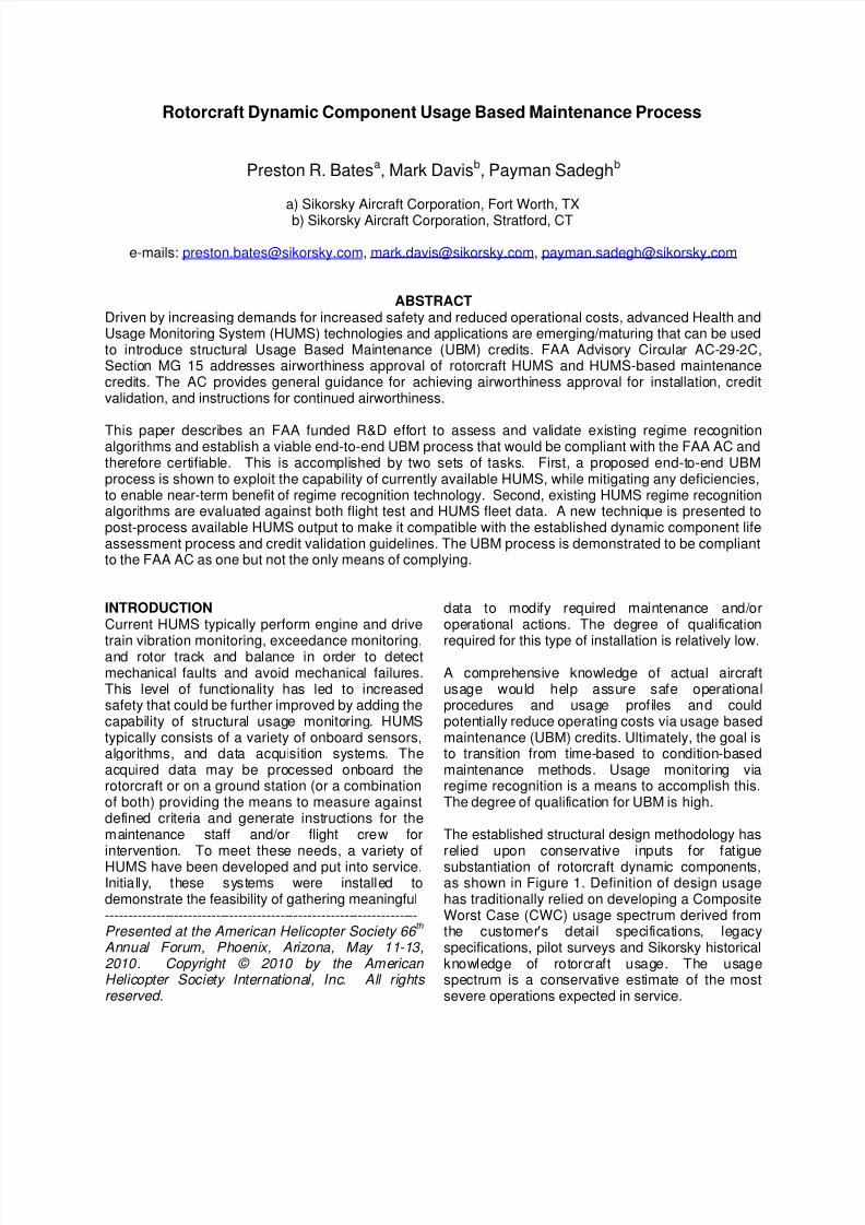
Rotorcraft Dynamic Component Usage Based Maintenance Process
Preston R. Batesa, Mark Davisb, Payman Sadeghb
a) Sikorsky Aircraft Corporation, Fort Worth, TX
b) Sikorsky Aircraft Corporation, Stratford, CT
e-mails: [email protected], [email protected], [email protected]
ABSTRACTDriven by increasing demands for increased safety and reduced operational costs, advanced Health andUsage Monitoring System (HUMS) technologies and applications are emerging/maturing that can be usedto introduce structural Usage Based Maintenance (UBM) credits. FAA Advisory Circular AC-29-2C,Section MG 15 addresses airworthiness approval of rotorcraft HUMS and HUMS-based maintenancecredits. The AC provides general guidance for achieving airworthiness approval for installation, creditvalidation, and instructions for continued airworthiness.
This paper describes an FAA funded R&D effort to assess and validate existing regime recognitionalgorithms and establish a viable end-to-end UBM process that would be compliant with the FAA AC andtherefore certifiable. This is accomplished by two sets of tasks. First, a proposed end-to-end UBMprocess is shown to exploit the capability of currently available HUMS, while mitigating any deficiencies,to enable near-term benefit of regime recognition technology. Second, existing HUMS regime recognitionalgorithms are evaluated against both flight test and HUMS fleet data. A new technique is presented topost-process available HUMS output to make it compatible with the established dynamic component lifeassessment process and credit validation guidelines. The UBM process is demonstrated to be compliantto the FAA AC as one but not the only means of complying.
INTRODUCTIONCurrent HUMS typically perform engine and drive
train vibration monitoring, exceedance monitoring,and rotor track and balance in order to detectmechanical faults and avoid mechanical failures.This level of functionality has led to increasedsafety that could be further improved by adding thecapability of structural usage monitoring. HUMStypically consists of a variety of onboard sensors,algorithms, and data acquisition systems. Theacquired data may be processed onboard therotorcraft or on a ground station (or a combinationof both) providing the means to measure againstdefined criteria and generate instructions for themaintenance staff and/or flight crew forintervention. To meet these needs, a variety ofHUMS have been developed and put into service.Initially, these systems were installed todemonstrate the feasibility of gathering meaningful--------------------------------------------------------------------Presented at the American Helicopter Society 66
th
Annual Forum, Phoenix, Arizona, May 11-13,2010. Copyright © 2010 by the American Helicopter Society International, Inc. All rights reserved.
data to modify required maintenance and/oroperational actions. The degree of qualification
required for this type of installation is relatively low.
A comprehensive knowledge of actual aircraftusage would help assure safe operationalprocedures and usage profiles and couldpotentially reduce operating costs via usage basedmaintenance (UBM) credits. Ultimately, the goal isto transition from time-based to condition-basedmaintenance methods. Usage monitoring viaregime recognition is a means to accomplish this.The degree of qualification for UBM is high.
The established structural design methodology hasrelied upon conservative inputs for fatiguesubstantiation of rotorcraft dynamic components,as shown in Figure 1. Definition of design usagehas traditionally relied on developing a CompositeWorst Case (CWC) usage spectrum derived fromthe customer's detail specifications, legacyspecifications, pilot surveys and Sikorsky historicalknowledge of rotorcraft usage. The usagespectrum is a conservative estimate of the mostsevere operations expected in service.

8/8/2019 +AHS Dynamic Component UBM_final 100408
http://slidepdf.com/reader/full/ahs-dynamic-component-ubmfinal-100408 2/13
Loads for these regimes are initially determinedthrough fatigue flight loads analysis, either usinganalytical flight simulation or by scaling appropriatetest data. This is followed up by flight loads surveytesting on prototype aircraft, where in-flight loadsdata for each maneuver are recorded from theinstrumented components. During these flight testprograms, the pilots are given a flight card thatdescribes the specifics of a maneuver, for examplea 2.5g symmetric pull-up at 150 knots. Data istypically recorded starting from a steady statecondition and then ended once the aircraft hasrecovered from the transient portion of themaneuver. A 95
thpercentile value of the recorded
vibratory flight loads is conservatively used foranalysis of steady maneuvers. For transientmaneuvers where significant load variability isexpected, cycle counting methods are used toobtain a distribution of loads.
These data are then processed by ground testengineers, who, with the use of full scalecomponent strength S-N curves with establishedstrength knockdowns, and determine calculatedretirement times (CRT) for the assumed usage.Along with regular inspection intervals, this isconsidered a reliable and safe approach for fatiguedesign and part life management and has beenapproved by the FAA for S-92 operations.
Figure 1 Inputs for Current Dynamic ComponentCRT Calculation
One potential benefit of HUMS is that it canmonitor and record the regimes that are flown oneach aircraft in fleet. The Original EquipmentManufacturer (OEM) can then compare the actualusage spectrum for an individual aircraft or fleet tothe CWC design usage spectrum to see whencomponents must be inspected or retired.Component loads would still be assumed for eachregime based on existing flight test data. Thismethod is called “usage based component
retirement” whereby UBM credits could be given todelay the time until parts are retired.
The application of HUMS for UBM credits presentschallenging certification issues related to HUMShardware and software certification, for both theairborne and ground based parts of the system.FAA Advisory Circular AC-29-2C, Section MG 15(Ref. 1), addresses airworthiness approval ofHUMS. The AC provides guidance for achievingairworthiness approval for installation, creditvalidation, and continued airworthiness instructionsfor a full range of HUMS application. Installationincludes all the equipment needed for the end-to-end application that is associated with acquiring,storing, processing, and displaying the HUMSapplication data, including airborne and ground-based equipment. Credit validation includesevidence of effectiveness for the developedalgorithms, acceptance limits, trend setting data,
tests, etc., and the demonstration methodsemployed. A plan is needed to ensure continuedairworthiness of those parts that could change withtime or usage and includes the methods used toensure continued airworthiness. The ACestablishes an acceptable means, but not the onlymeans of certifying a rotorcraft HUMS and HUMS-based maintenance credits.
OBJECTIVEWhile advanced usage monitoring and flightregime recognition (RR) algorithms have beendemonstrated, none have been fully validated and
certified for UBM credit application. Further, anend-to-end UBM process also needs to bedeveloped and validated in compliance with Ref. 1.
The objective of the program described in thispaper is to address both of these needs by utilizingflight test and fleet data to support the validationand demonstration of HUMS operationrequirements, technologies, and processes and tocollect and substantiate structural usage data.Existing usage monitoring and flight RRtechnologies for structures are used in thisprogram. The primary sub-objectives of this effort
are to:1) develop an end-to-end UBM process thataddresses the issues of HUMS installation,credit validation, and continued airworthinessin accordance with AC-29-2C Section MG 15
2) demonstrate a combination of on-aircraft andoff-aircraft usage monitoring RR algorithmsthat can be used for UBM credit application
StrengthKnockdown
95t
PclLoads
CWC Usage

8/8/2019 +AHS Dynamic Component UBM_final 100408
http://slidepdf.com/reader/full/ahs-dynamic-component-ubmfinal-100408 3/13
APPROACHThe high level objective of UBM credit applicationis to adjust a component maintenance interval(e.g., retirement time) while assuring safety andreliability. The approach undertaken in this projectto fulfill this objective is summarized as follows.
Establish a UBM end-to-end process incompliance with the AC considering boththe current state of S-92 HUMS technologyand level of manufacturer involvement
Select S-92 UBM candidate dynamiccomponents and identify the associateddamaging regimes
Using S-92 flight test and fleet data,validate selected damaging regimes anddevelop technology to mitigate risk in theend-to-end process for UBM credit
UBM END-TO-END PROCESSCalculation of a UBM credit, or usage basedretirement time, is predicated on the ability toconservatively estimate accrued damage frommonitored part usage as notionally shown in Figure2. This process compares the CWC conservativedamage model to that for measured usage. Safetyis first maintained by estimating damage to bemore severe than the actual damage accrual.Additional safety margins may also be imposedbased on all of the elements in the end-to-endprocess.
Figure 2 Notional UBM Process
Actual measured usage may be applied to updatethe time for dynamic component maintenanceaction or retirement. This is expected most oftento take the form of a credit, although retirementtime could be debited if operator usage is found tobe more severe than the CWC. The UBMadjustment could be applied at discrete decisionpoints, e.g. after a certain number of flight hoursthat correspond to a predefined life threshold or
even in a continuous mode as flight data isrecorded. In addition, various life calculationoptions may be envisioned ranging from semi-automated offboard software and processes run bythe OEM, to fully automated software in the groundstation or onboard in the HUMS. Combinations ofthese options present various opportunities forinsertion of UBM technologies in current practicesand to grow and expand application of UBM creditas the technology matures.
The UBM end-to-end process outlined here isdeveloped accordingly for an offboard creditevaluation process and one-time life adjustment.In the future, as more experience is gained with theuse of UBM technologies, one may envision ascenario where fully automated software isdeveloped and maintained by the manufacturer butdelivered to the fleet operator for processing in theground station. Ultimately, UBM software could be
implemented in a fully onboard fashion.
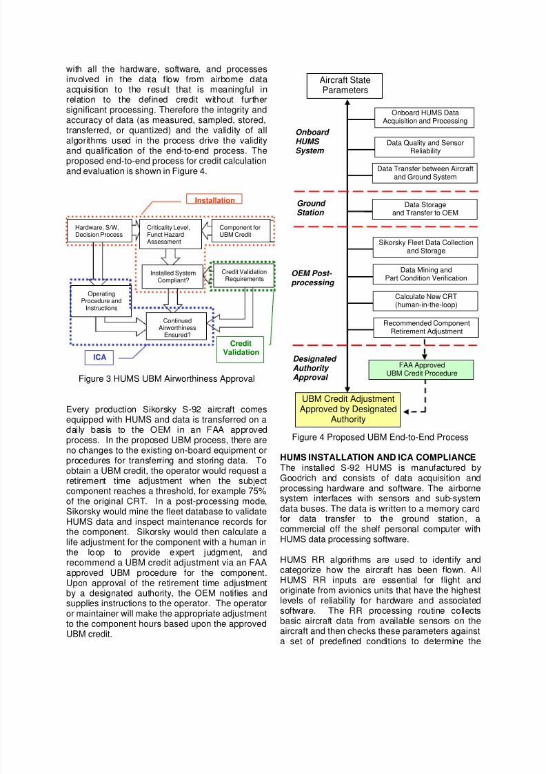
Ref. 1 provides guidance for achievingairworthiness approval for HUMS installation, creditvalidation, and instructions for continuedairworthiness (ICA), in particular for any process orapplication that intervenes with maintenance ofrotorcraft flight critical components. As Figure 3shows, installation, credit validation, and ICA arenot completely independent.
Installation requirements show that the system asinstalled, including all the hardware, software, and
decision processes, complies with the criticalitylevel associated with the component for which acredit is sought.
Credit validation requires that (1) accrued andaccumulated damage must be founded on physicsof fatigue analysis and material reliability and (2)reliability factors must be built to deal with varioussources of uncertainty in damage calculations.Additionally empirical evidence must be producedto demonstrate the validity of the methodology.Credit validation requirements are particularlyimportant to demonstrate compliance of the
installed system and its continued airworthiness.
In order for the system to remain in service,instructions for continued airworthiness (ICA) arerequired to demonstrate that operating proceduresand instructions are available to the operator.
The term "end-to-end" as used by AC-29 MG 15 isintended to address the boundaries of the HUMSapplication and the effect on the aircraft. Theboundaries are the starting point that corresponds
8/8/2019 +AHS Dynamic Component UBM_final 100408
http://slidepdf.com/reader/full/ahs-dynamic-component-ubmfinal-100408 4/13
with all the hardware, software, and processesinvolved in the data flow from airborne dataacquisition to the result that is meaningful inrelation to the defined credit without furthersignificant processing. Therefore the integrity andaccuracy of data (as measured, sampled, stored,transferred, or quantized) and the validity of allalgorithms used in the process drive the validityand qualification of the end-to-end process. Theproposed end-to-end process for credit calculationand evaluation is shown in Figure 4.
Figure 3 HUMS UBM Airworthiness Approval
Every production Sikorsky S-92 aircraft comesequipped with HUMS and data is transferred on adaily basis to the OEM in an FAA approvedprocess. In the proposed UBM process, there areno changes to the existing on-board equipment orprocedures for transferring and storing data. Toobtain a UBM credit, the operator would request aretirement time adjustment when the subjectcomponent reaches a threshold, for example 75%of the original CRT. In a post-processing mode,Sikorsky would mine the fleet database to validateHUMS data and inspect maintenance records forthe component. Sikorsky would then calculate a
life adjustment for the component with a human inthe loop to provide expert judgment, andrecommend a UBM credit adjustment via an FAAapproved UBM procedure for the component.Upon approval of the retirement time adjustmentby a designated authority, the OEM notifies andsupplies instructions to the operator. The operatoror maintainer will make the appropriate adjustmentto the component hours based upon the approvedUBM credit.
Figure 4 Proposed UBM End-to-End Process
HUMS INSTALLATION AND ICA COMPLIANCEThe installed S-92 HUMS is manufactured byGoodrich and consists of data acquisition andprocessing hardware and software. The airbornesystem interfaces with sensors and sub-systemdata buses. The data is written to a memory cardfor data transfer to the ground station, acommercial off the shelf personal computer with
HUMS data processing software.
HUMS RR algorithms are used to identify andcategorize how the aircraft has been flown. AllHUMS RR inputs are essential for flight andoriginate from avionics units that have the highestlevels of reliability for hardware and associatedsoftware. The RR processing routine collectsbasic aircraft data from available sensors on theaircraft and then checks these parameters againsta set of predefined conditions to determine the
CreditValidation
ICA
Installation
Component forUBM Credit
Criticality Level,Funct HazardAssessment
Hardware, S/W,Decision Process
Installed SystemCompliant?
Credit ValidationRequirements
OperatingProcedure and
Instructions
ContinuedAirworthiness
Ensured?
Onboard HUMS System
Ground Station
Aircraft StateParameters
Data Transfer between Aircraftand Ground System
Data Storageand Transfer to OEM
Sikorsky Fleet Data Collectionand Storage
Data Mining andPart Condition Verification
Data Quality and SensorReliability
Onboard HUMS DataAcquisition and Processing
Calculate New CRT(human-in-the-loop)
Recommended ComponentRetirement Adjustment
OEM Post- processing
UBM Credit Adjustment
Approved by DesignatedAuthority
FAA ApprovedUBM Credit Procedure
Designated Authority Approval

8/8/2019 +AHS Dynamic Component UBM_final 100408
http://slidepdf.com/reader/full/ahs-dynamic-component-ubmfinal-100408 5/13
aircraft flight regime. The actual identification of aregime is accomplished by using configurabledefinition tables. A definition that is used for theidentification of a regime consists of a set ofexpressions that are combined using BooleanCompound “AND” logic. If all expressions are truefor a particular definition, then the aircraft isdetermined to be in the defined regime. Theregime recognition data flow is illustrated in Figure5 showing standard input and output data types.
Input data includes basic aircraft and system data,external atmosphere derived data, aircraft attitude,stick position, and accelerations. The keyperformance parameters are classified into bandssuch as Gross Weight, Airspeed, Altitude Density,Engine Torque, Load Factor and Rotor speed. Theoutput includes derived parameters, Regimerecord, Event record, and Log record. Additionaloutputs include derived parameter calculations
such as heading, ground velocity, weight onwheels flag, etc. HUMS regime packet data outputis updated every second.
During the development of the S-92 RR algorithms,Sikorsk y mapped the process of regimedetermination into a series of logic diagrams basedon the available HUMS parameters. Flightmaneuvers were separated into low and highspeed flight regimes, while ground based regimeswere split into Ground Operations, Takeoffs, andLandings. Entry to low speed flight occurs whenWeight-On-Wheels, landing, and Takeoff “Flags”
are false and airspeed is below 40 knots. Thespecific low speed regime is determined bystepping through the logic tree. Similarly, theregimes are determined for High Speed, above 40knots. This approach ensures that each regime isunique and mutually exclusive from the rest.
All HUMS software algorithms were evaluated inthe Sikorsky HUMS Development Laboratory priorto installation on airborne equipment. Onceinstalled, regime processing occurs continuouslyand in the background, when the main processingunit is powered. Regimes are defined in a manner
that allows efficient search and a smooth transitionbetween regimes while eliminating gaps. The datavalidity for each parameter used in an expressionis also checked. If a parameter used for a definitionis invalid, the regime is marked as “Undetermined.”If all of the parameters are valid and none of thedefinitions are found to match, then the regime isdeclared as “Unrecognized”.
The installed S-92 HUMS hardware and softwaresatisfy FAA certification requirements and have
demonstrated continued airworthiness for over150,000 of fleet flight hours of operation. Inaddition, the methods for data transfer to theground station and subsequent data transfer andstorage at the OEM have demonstratedcompliance by employing established datamanagement and data integrity methods for use inmechanical diagnostics applications. Likewise, RRalgorithms have been functioning consistently andprovided usage information for every aircraft in thefleet. However, the RR algorithms have not beenverified for compliance with credit validationrequirements.
Figure 5 Current HUMS RR Algorithms
HUMS RR CREDIT VALIDATION EVALUATIONIn order to meet credit validation compliancecriteria of Ref. 1, the component(s) for which UBMcredit is sought must be selected. Definition ofthese components is based on a variety ofconsiderations such as business objectives (e.g.cost of early retirement or replacement of the
Basic Aircraft Parameters
-External CargoWeight, GrossWeight,APU Speed, MainRotor Speed,
Engine NP, EngineTGT, Engine TorqueGroundspeed, RadarAltitude, Velocity
Air Data ParametersOutside AirTemperature,Barometric Altitude,Calibrated Airspeed,Barometric Rate ofClimb
Aircraft AttitudeParameters
Heading Attitude,Pitch Attitude, RollAttitude, Yaw Rate
Stick PositionsLongitudinal CyclicPosition, LateralCyclic Position, PedalPosition, CollectiveStick Position
Aircraft DiscretesWOW, MR BrakeApplied, ADC ID,AHRS ID
AccelerationLongitudinal (AFSC),Lateral (AFSC),Vertical Acceleration(MDC)
Inputs
Regime Packet DataA record of
each regimecontaining thestart time andduration
Prorates appliedof each regime(optional).
Logged DataBasic aircraftparameter dataand derivedparameter data.
Event DataA record ofeach event.
Derived ParametersGrd Speed,Aircraft heading,etc…
Outputs
HUMS On-Board
RR Process

8/8/2019 +AHS Dynamic Component UBM_final 100408
http://slidepdf.com/reader/full/ahs-dynamic-component-ubmfinal-100408 6/13
component) and ease or validity of applying theUBM credit process on the component.
To select components for this effort, all life-limitedS-92 components were investigated. In a previousSikorsky research and development effort, theS-92 hub was the subject of a credit evaluationbased primarily on direct measurement ofcentrifugal Ground-Air-Ground (GAG) cycles whichare the major contributor to fatigue damage for thatcomponent. In order to build upon that experience,the components selected for this program targeteda critical steady state maneuver whose damage isproportional to the total time spent in the regime.The swashplate was selected because it showedthe most damage from steady regimes. Furtherexamination of the UBM credit validation process isachieved by measuring transient maneuverswhose damage is dependent upon the number ofoccurrences. The Main Rotor (MR) damper was
selected because it had the largest contribution ofdamage from transient regimes. Also, the otherMR damper damaging maneuvers are similar tothe swashplate, so that the verification of regimesfor that component will be directly applicable.Figure 6 illustrates the S-92 components selectedfor UBM credit examination.
The swashplate and MR damper fatiguesubstantiation documents show that high bankangle steady right turns, which have higher loadsthan the corresponding left turns, and symmetricpullout transient maneuvers are the most
damaging regimes for these components. Ratherthan try to rigorously evaluate all HUMS regimes,the developed approach focuses on key regimesthat are found to be damaging to selectedcomponents that are considered good candidatesfor UBM. The RR analysis was therefore narrowedto these types of maneuvers for evaluation of creditvalidation compliance in the end-to-end UBMprocess.
The damage calculation process for UBM creditsremains unchanged, adhering to existing FAAapproved fatigue substantiation methodology for
ensuring aircraft flight safety and airworthiness.Material strength and loads shown in Figure 1 arenot adjusted, and so the UBM credit validationevaluation will consider only items related to usagemonitoring via HUMS RR algorithms.
Evaluation of HUMS regimes requires a set ofvalidation, or ‘truth’ data. The primary set of truthdata is considered to be the pilot declarations fromscripted flight tests. This project utilized flightloads survey data from a HUMS equipped S-92
aircraft that was fully outfitted with load measuringinstrumentation. In addition, a representative1,600 flight hour sample of existing S-92 fleet datawas used to further validate algorithm performanceas compared to the conservative CWC designusage spectrum.
Figure 6 S-92 Components for UBM Study
An S-92 flight loads survey provided an opportunity
to gather HUMS information in a controlledenvironment that is comprised of precise maneuverexecution and rigorous measurements, therebyproviding a valuable set of truth data for RRalgorithm verification. A significant portion of theevaluation process involves referencing HUMSdata to S-92 flight test data available on theSikorsky Advanced Data Acquisition & ProcessingSystem (ADAPS). Run Logs are stored in ADAPSand represent formal versions of the pilot cardwhich may have been modified during the test, anddocument data for configuration and maneuvers.ADAPS also stores all of the recorded data fromthe flight test that can be plotted as a time history.
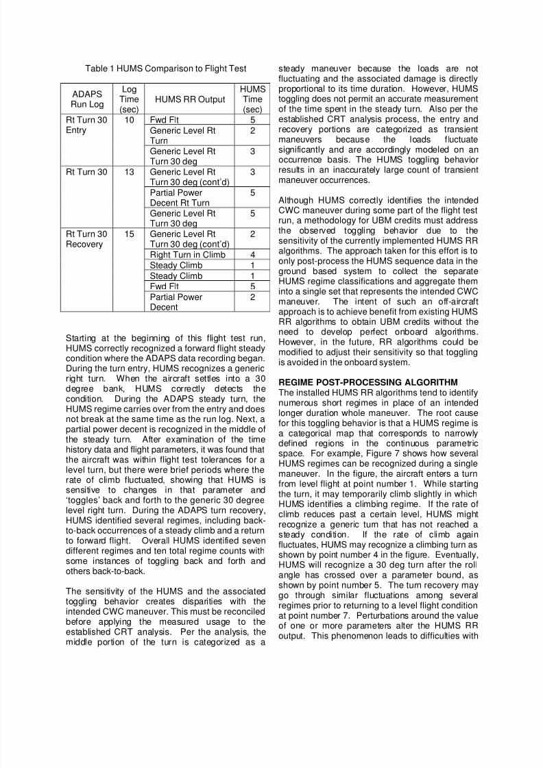
HUMS and ADAPS traces can be compared fordata integrity and accuracy. Table 1 shows a sideby side comparison for a typical CWC maneuversequence: 30 degree right turn entry, steady turn,and recovery. As shown, there is not a one-to-onecorrespondence between HUMS and the CWCmaneuvers. Instead, HUMS typically identifiesnumerous regimes.
MR DamperTransient Maneuver
Occurrences
MR HubCF GAG Cycles
MR SwashplateSteady Maneuver
Durations
8/8/2019 +AHS Dynamic Component UBM_final 100408
http://slidepdf.com/reader/full/ahs-dynamic-component-ubmfinal-100408 7/13
Table 1 HUMS Comparison to Flight Test
ADAPSRun Log
LogTime(sec)
HUMS RR OutputHUMSTime(sec)
Fwd Flt 5
Generic Level RtTurn 2
Rt Turn 30
Entry
10
Generic Level RtTurn 30 deg
3
Generic Level RtTurn 30 deg (cont’d)
3
Partial PowerDecent Rt Turn
5
Rt Turn 30 13
Generic Level RtTurn 30 deg
5
Generic Level RtTurn 30 deg (cont’d)
2
Right Turn in Climb 4
Steady Climb 1Steady Climb 1Fwd Flt 5
Rt Turn 30Recovery
15
Partial PowerDecent
2
Starting at the beginning of this flight test run,HUMS correctly recognized a forward flight steadycondition where the ADAPS data recording began.During the turn entry, HUMS recognizes a genericright turn. When the aircraft settles into a 30degree bank, HUMS correctly detects thecondition. During the ADAPS steady turn, theHUMS regime carries over from the entry and doesnot break at the same time as the run log. Next, apartial power decent is recognized in the middle ofthe steady turn. After examination of the timehistory data and flight parameters, it was found thatthe aircraft was within flight test tolerances for alevel turn, but there were brief periods where therate of climb fluctuated, showing that HUMS issensitive to changes in that parameter and‘toggles’ back and forth to the generic 30 degreelevel right turn. During the ADAPS turn recovery,HUMS identified several regimes, including back-to-back occurrences of a steady climb and a return
to forward flight. Overall HUMS identified sevendifferent regimes and ten total regime counts withsome instances of toggling back and forth andothers back-to-back.
The sensitivity of the HUMS and the associatedtoggling behavior creates disparities with theintended CWC maneuver. This must be reconciledbefore applying the measured usage to theestablished CRT analysis. Per the analysis, themiddle portion of the turn is categorized as a
steady maneuver because the loads are notfluctuating and the associated damage is directlyproportional to its time duration. However, HUMStoggling does not permit an accurate measurementof the time spent in the steady turn. Also per theestablished CRT analysis process, the entry andrecovery portions are categorized as transientmaneuvers because the loads f luctuatesignificantly and are accordingly modeled on anoccurrence basis. The HUMS toggling behaviorresults in an inaccurately large count of transientmaneuver occurrences.
Although HUMS correctly identifies the intendedCWC maneuver during some part of the flight testrun, a methodology for UBM credits must addressthe observed toggling behavior due to thesensitivity of the currently implemented HUMS RRalgorithms. The approach taken for this effort is toonly post-process the HUMS sequence data in the
ground based system to collect the separateHUMS regime classifications and aggregate theminto a single set that represents the intended CWCmaneuver. The intent of such an off-aircraftapproach is to achieve benefit from existing HUMSRR algorithms to obtain UBM credits without theneed to develop perfect onboard algorithms.However, in the future, RR algorithms could bemodified to adjust their sensitivity so that togglingis avoided in the onboard system.
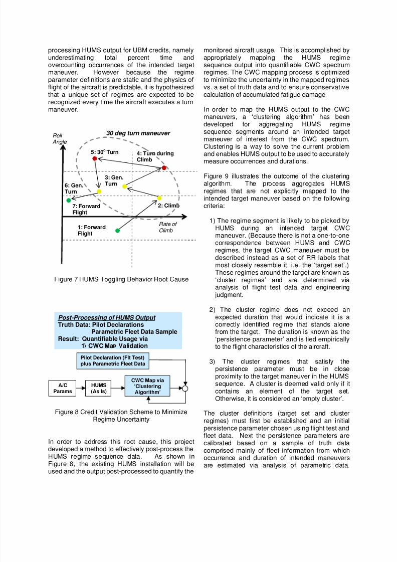
REGIME POST-PROCESSING ALGORITHMThe installed HUMS RR algorithms tend to identify
numerous short regimes in place of an intendedlonger duration whole maneuver. The root causefor this toggling behavior is that a HUMS regime isa categorical map that corresponds to narrowlydefined regions in the continuous parametricspace. For example, Figure 7 shows how severalHUMS regimes can be recognized during a singlemaneuver. In the figure, the aircraft enters a turnfrom level flight at point number 1. While startingthe turn, it may temporarily climb slightly in whichHUMS identifies a climbing regime. If the rate ofclimb reduces past a certain level, HUMS mightrecognize a generic turn that has not reached a
steady condition. If the rate of climb againfluctuates, HUMS may recognize a climbing turn asshown by point number 4 in the figure. Eventually,HUMS will recognize a 30 deg turn after the rollangle has crossed over a parameter bound, asshown by point number 5. The turn recovery maygo through similar fluctuations among severalregimes prior to returning to a level flight conditionat point number 7. Perturbations around the valueof one or more parameters alter the HUMS RRoutput. This phenomenon leads to difficulties with
8/8/2019 +AHS Dynamic Component UBM_final 100408
http://slidepdf.com/reader/full/ahs-dynamic-component-ubmfinal-100408 8/13
processing HUMS output for UBM credits, namelyunderestimating total percent time andovercounting occurrences of the intended targetmaneuver. However because the regimeparameter definitions are static and the physics offlight of the aircraft is predictable, it is hypothesizedthat a unique set of regimes are expected to berecognized every time the aircraft executes a turnmaneuver.
Figure 7 HUMS Toggling Behavior Root Cause
Figure 8 Credit Validation Scheme to MinimizeRegime Uncertainty
In order to address this root cause, this projectdeveloped a method to effectively post-process theHUMS regime sequence data. As shown inFigure 8, the existing HUMS installation will beused and the output post-processed to quantify the
monitored aircraft usage. This is accomplished byappropriately mapping the HUMS regimesequence output into quantifiable CWC spectrumregimes. The CWC mapping process is optimizedto minimize the uncertainty in the mapped regimesvs. a set of truth data and to ensure conservativecalculation of accumulated fatigue damage.
In order to map the HUMS output to the CWCmaneuvers, a ‘clustering algorithm’ has beendeveloped for aggregating HUMS regimesequence segments around an intended targetmaneuver of interest from the CWC spectrum.Clustering is a way to solve the current problemand enables HUMS output to be used to accuratelymeasure occurrences and durations.
Figure 9 illustrates the outcome of the clusteringalgorithm. The process aggregates HUMSregimes that are not explicitly mapped to the
intended target maneuver based on the followingcriteria:
1) The regime segment is likely to be picked byHUMS during an intended target CWCmaneuver. (Because there is not a one-to-onecorrespondence between HUMS and CWCregimes, the target CWC maneuver must bedescribed instead as a set of RR labels thatmost closely resemble it, i.e. the ‘target set’.)These regimes around the target are known as‘cluster regimes’ and are determined viaanalysis of flight test data and engineering
judgment.
2) The cluster regime does not exceed anexpected duration that would indicate it is acorrectly identified regime that stands alonefrom the target. The duration is known as the‘persistence parameter’ and is tied empiricallyto the flight characteristics of the aircraft.
3) The cluster regimes that satisfy thepersistence parameter must be in closeproximity to the target maneuver in the HUMSsequence. A cluster is deemed valid only if it
contains an element of the target set.Otherwise, it is considered an ‘empty cluster’.
The cluster definitions (target set and clusterregimes) must first be established and an initialpersistence parameter chosen using flight test andfleet data. Next the persistence parameters arecalibrated based on a sample of truth datacomprised mainly of fleet information from whichoccurrence and duration of intended maneuversare estimated via analysis of parametric data.
Post-Processing of HUMS Output Truth Data: Pilot Declarations
Parametric Fleet Data SampleResult: Quantifiable Usage via
1 CWC Ma Validation
HUMS
(As Is)
CWC Map via‘Clustering
Algorithm’
A/C
Params
Pilot Declaration (Flt Test)plus Parametric Fleet Data
Roll Angle
Rate of Climb
1: ForwardFlight
2: Climb
3: Gen.Turn
5: 30o Turn
7: ForwardFlight
30 deg turn maneuver
4: Turn duringClimb
6: Gen.Turn
8/8/2019 +AHS Dynamic Component UBM_final 100408
http://slidepdf.com/reader/full/ahs-dynamic-component-ubmfinal-100408 9/13
Finally, the model is checked against all availabletruth from flight test and the fleet to determine itsvalidity and quantify its reliability.
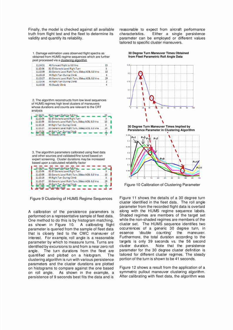
Figure 9 Clustering of HUMS Regime Sequences
A calibration of the persistence parameters isperformed on a representative sample of fleet data.One method to do this is by histogram matching,as shown in Figure 10. A calibrating flightparameter is queried from the sample of fleet datathat is closely tied to the CWC maneuver ofinterest. For example, roll angle is a reasonableparameter by which to measure turns. Turns areidentified by excursions to and from a near zero rollangle. The turn durations from the fleet arequantified and plotted on a histogram. Theclustering algorithm is run with various persistenceparameters and the cluster durations are plottedon histograms to compare against the one basedon roll angle. As shown in the example, apersistence of 9 seconds best fits the data and is
reasonable to expect from aircraft performancecharacteristics. Either a single persistenceparameter can be employed or different valuestailored to specific cluster maneuvers.
Figure 10 Calibration of Clustering Parameter
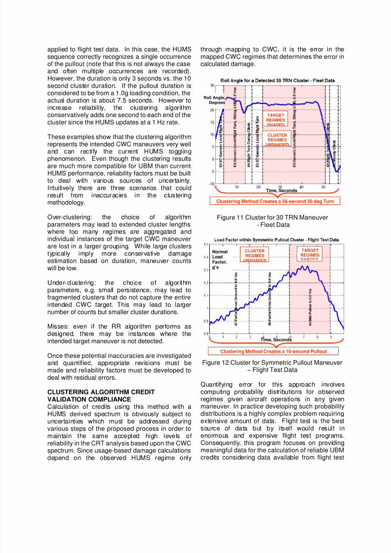
Figure 11 shows the details of a 30 degree turncluster identified in the fleet data. The roll angleparameter from the recorded flight data is overlaidalong with the HUMS regime sequence labels.Shaded regimes are members of the target setwhile the non-shaded regimes are members of thecluster set. The HUMS sequence identifies twooccurrences of a generic 30 degree turn, in
essence ‘double counting’ the maneuver.Furthermore, the total duration according to thetargets is only 39 seconds vs. the 56 secondcluster duration. Note that the persistenceparameter for the 30 degree cluster definition istailored for different cluster regimes. The steadyportion of the turn is shown to be 41 seconds.
Figure 12 shows a result from the application of asymmetric pullout maneuver clustering algorithm.After calibrating with fleet data, the algorithm was
P=1 P=3P =5 P =7
P=9
P=11
P=13
30 Degree Turn Maneuver Times Implied byPersistence Parameter in Clustering Algorithm
30 Degree Turn Maneuver Times Obtained
from Fleet Parametric Roll Angle Data
2. The algorithm reconstructs from low level sequencesof HUMS regimes high level clusters of maneuverswhose durations and counts are relevant to the CRTanalysis
11:15:06 82-87:Generic Level Ri ght Turn 3
11:15:06 82-87:Generic Level Right Turn 3
3. The algorithm parameters calibrated using fleet dataand other sources and validated/fine tuned based onexpert screening. Cluster durations may be increasedbased upon a calculated reliability factor
11:15:06 82-87:Generic Level Ri ght Turn 3
1. Damage estimation uses observed flight spectra as
obtained from HUMS regime sequences which are furtherpost processed via a clustering algorithm
8/8/2019 +AHS Dynamic Component UBM_final 100408
http://slidepdf.com/reader/full/ahs-dynamic-component-ubmfinal-100408 10/13
applied to flight test data. In this case, the HUMSsequence correctly recognizes a single occurrenceof the pullout (note that this is not always the caseand often multiple occurrences are recorded).However, the duration is only 3 seconds vs. the 10second cluster duration. If the pullout duration isconsidered to be from a 1.0g loading condition, theactual duration is about 7.5 seconds. However toincrease reliability, the clustering algorithmconservatively adds one second to each end of thecluster since the HUMS updates at a 1 Hz rate.
These examples show that the clustering algorithmrepresents the intended CWC maneuvers very welland can rectify the current HUMS togglingphenomenon. Even though the clustering resultsare much more compatible for UBM than currentHUMS performance, reliability factors must be builtto deal with various sources of uncertainty.Intuitively there are three scenarios that could
result from inaccuracies in the clusteringmethodology.
Over-clustering: the choice of algorithmparameters may lead to extended cluster lengthswhere too many regimes are aggregated andindividual instances of the target CWC maneuverare lost in a larger grouping. While large clusterstypically imply more conservative damageestimation based on duration, maneuver countswill be low.
Under-clustering: the choice of algorithm
parameters, e.g. small persistence, may lead tofragmented clusters that do not capture the entireintended CWC target. This may lead to largernumber of counts but smaller cluster durations.
Misses: even if the RR algorithm performs asdesigned, there may be instances where theintended target maneuver is not detected.
Once these potential inaccuracies are investigatedand quantified, appropriate revisions must bemade and reliability factors must be developed todeal with residual errors.
CLUSTERING ALGORITHM CREDITVALIDATION COMPLIANCECalculation of credits using this method with aHUMS derived spectrum is obviously subject touncertainties which must be addressed duringvarious steps of the proposed process in order tomaintain the same accepted high levels ofreliability in the CRT analysis based upon the CWCspectrum. Since usage-based damage calculationsdepend on the observed HUMS regime only
through mapping to CWC, it is the error in themapped CWC regimes that determines the error incalculated damage.
Figure 11 Cluster for 30 TRN Maneuver- Fleet Data
Figure 12 Cluster for Symmetric Pullout Maneuver – Flight Test Data
Quantifying error for this approach involvescomputing probability distributions for observedregimes given aircraft operations in any givenmaneuver. In practice developing such probabilitydistributions is a highly complex problem requiringextensive amount of data. Flight test is the bestsource of data but by itself would result inenormous and expensive flight test programs.Consequently, this program focuses on providingmeaningful data for the calculation of reliable UBMcredits considering data available from flight test
Time, Seconds
NormalLoadFactor,g’s
Clustering Method Creates a 10-second Pullout
TARGETREGIMES
CLUSTERREGIMES
UNSHADED
Roll Angle,Degrees
Time, Seconds
Clustering Method Creates a 56-second 30 deg Turn
TARGETREGIMESSHADED
CLUSTERREGIMES
UNSHADED

8/8/2019 +AHS Dynamic Component UBM_final 100408
http://slidepdf.com/reader/full/ahs-dynamic-component-ubmfinal-100408 11/13
and the operational fleet. Success for determiningappropriate reliability factors is increased by
1) focusing on the damaging regimes forselected dynamic components,
2) combining experimental data with fleet data toimprove the accuracy of HUMS errorestimates, and
3) keeping a engineering expert in the loop toprovide sound judgment based on knowledgeof fatigue substantiating parameters andaircraft performance.
Figure 13 shows the overall process for theclustering algorithm reliability assessment. Afterthe algorithm has been defined for the CWCmaneuver of interest, it is tested to determine howit detects all occurrences of maneuvers in thevalidation data sets. Since the flight test data iscrucial to the clustering algorithm, examination and
filtering of such data prior to use is essential.Indications of overclustering and underclusteringare noted and the persistence parameter tailoredas necessary. If there are missed targets, theseare further investigated by examining availableloads and state parameters to see if they aredamage causing events. If so, the possibility ofmodifying the cluster definition is examined, forexample expanding the target set definitions toinclude the damaging event. If implemented, theadjusted clustering algorithm is checked again withthe validation data. If the existing clusterdefinitions can’t be changed to include these
regimes, another option is to create a new clusterdefinition for these maneuvers. These steps arerepeated until the cluster definitions are optimized.Final statistics are determined to develop reliabilityfactors for maneuver duration and counts. Forthose missed conditions that are not detected,similar statistics are generated and used todetermine appropriate reliability factors.
Once the cluster definition for a CWC maneuverhas undergone this process, no more improvementcan be gained from the clustering algorithmcapabilities, and the associated reliability can be
determined through the analysis of errors for thethree categories described earlier, i.e. over-clustering, under-clustering, and misses.
The reliability process described applies to theestimate of accrued actual part damage based onrecorded HUMS data. Any missing data in theHUMS records are filled with the original designCWC usage. When calculated the UBM credit,future usage is assumed to be CWC.
The reliability model for credit validationcompliance will also provide data to be consideredfor a controlled introduction to service strategy.Such a plan includes a gradual transition from thecurrent time-based practice. During the time thatmaintenance decisions are being made via time-based methods, independent verification meansmay be employed to ensure correctness of HUMSbased damage computations.
Figure 13 Cluster Algorithm ReliabilityAssessment
Finally it is noteworthy that the approach describedin this paper addresses calculation of credits atboth the serial number and part number levels.Tracking the usage on individual HUMS-equipped
Analyze
over/under
clustering
Developreliability
factors
Mine data for
occurrence of
“critical”
parametric
conditions
Conditions
damaging?
Develop
statistical
models of the
duration and
frequency of
undetected
conditions
Cluster can
be
modified?
Yes
Expand/revise
cluster
definition
Yes
No
Maneuvers
detected by
clustering
No
Yes
New clustercan be
created?
Yes
No
8/8/2019 +AHS Dynamic Component UBM_final 100408
http://slidepdf.com/reader/full/ahs-dynamic-component-ubmfinal-100408 12/13
aircraft tail numbers allows construction of thespecific usage history for the component serialnumber. In contrast, UBM credit at the partnumber level involves examining data over thefleet to determine a usage-based updated CWCspectrum which is not as severe as the originaldesign CWC but still encompasses all operationalaircraft. Sikorsky ground test and structuralmethods engineers have previously developed anapproach that is applicable to a fleet-wide UBMcredit validation (Ref. 2). This approach prescribesa reliability factor as the ratio of two suitablepercentiles (e.g. 90 to 50) of a probabilitydistribution fitted to the sampled points. Thisreliability factor would be applied to all UBMdamage calculations for a component.
CONCLUSIONSAn end-to-end process definition was presented forS-92 UBM credits that is believed to be compliant
with AC 29-2C, technically sound, and works withinthe available HUMS process. Currently airworthyhardware and procedures for HUMS datacollection are maintained that adhere to FAAstandards. The installed HUMS RR algorithms,while appropriate for general monitoring of aircraftusage, were evaluated against credit validationrequirements and found to be incompatible withSikorsky fatigue substantiation procedures in theirpresent implementation.
A new post-processing technique known as a‘clustering algorithm’ was developed that would be
a key ingredient to fulfill the FAA credit validationcompliance criteria by successfully mapping HUMSRR sequence output into selected damaging CWCregimes that can be used in the existing retirementtime analytical process. An importantconsideration in the development of the clusterdefinitions for damaging regimes is the integrity offlight test data. An engineer in the loop isnecessary to substantiate the accuracy of theverification data sets and to ensure that theclustering algorithm parameters are compatiblewith known physics of flight and aircraftperformance characteristics. A process to quantify
errors from the clustering algorithm was defined toensure the levels of reliability necessary for UBMcredit determination. The research described inthis paper is a substantial step forward toward therealization of HUMS-enabled UBM credits.
ACKNOWLEDGEMENTSThe authors wish to acknowledge Dr. XiaogongLee and Traci Stadtmueller of the FAA RotorcraftTechnical Center for their support of this workunder Agreement No: DTFACT-06-C-00002.
REFERENCES
1. Advisory Circular 29-2C, “Certification ofTransport category Rotorcraft,” U.S. Department ofTransportation, Federal Aviation Agency, 25 April2006.
2. Adams, D.O., Zhao, J., “Searching for theUsage Monitor Reliability Factor Using anAdvanced Fatigue Reliability Assessment Model,”American Helicopter Society 65th Annual Forum,Grapevine Texas, May 2009.

8/8/2019 +AHS Dynamic Component UBM_final 100408
http://slidepdf.com/reader/full/ahs-dynamic-component-ubmfinal-100408 13/13