Embed Size (px)
Citation preview

A highly parallel computing systemfor information retrieval*
by BEHROOZ PARHAM I
University of CaliforniaLos Angeles, California
INTRODUCTION
The tremendous expansion in the volume of recordedkno'wledge and the desirability of more sophisticatedretrieval techniques have resulted in a need for auto-mated information retrieval systems. However, the highcost, in programming and running time, implied by suchsystems has prevented their widespread use. This highcost stems from a mismatch between the problem to besolved and the conventional architecture of digitalcomputers, optimized for performing serial operations onfixed-size arrays of data.
It is evident that programming and processing costscan be reduced substantially through the use ofspecial-purpose computers, with parallel-processingcapabilities, optimized for non-arithmetic computations.This is true because the most common and time-con-suming operations encountered in information retrievalapplications (e.g., searching and sorting) can makeefficient use of parallelism.In this paper, a special-purpose highly parallel
system is proposed for information retrieval applica-tions. The proposed system is called RAPID, RotatingAssociative Processor for Information Dissemination,since it is similar in function to a conventional byte-serial associative processor and uses a rotating memorydevice. RAPID consists of an array processor used inconjunction with a head-per-track disk or drum memory(or any other circulating memory). The array processorconsists of a large number of identical cells controlled bya central unit and essentially acts as a filter between thelarge circulating memory and a central computer. Inother words, the capabilities of the array processor areused to search and mark the file. The relevant parts ofthe file are then selectively processed by the centralcomputer.
* This research was supported by the U.S. Office of NavalResearch, Mathematical and Information Sciences Division,Contract No. NOOOI4-69-A-0200-4027, NR 048-129.
PARALLELISM AND INFORMATIONRETRIEVAL
Information retrieval may be defined as selectiverecall of stored knowledge. Here, we do not considerinformation retrieval systems in their full generality butrestrict ourselves to reference and document retrievalsystems. Reference (document) retrieval is defined asthe selection of a set of references (documents) from alarger collection according to known criteria.
The processing functions required for informationretrieval are performed in three phases:
1. Translating the user query into a set of searchspecifications described in machine language.
2. Searching a large data base and selecting recordsthat satisfy the search criteria.
3. Preparing the output; e.g., formatting the records,extracting the required information, and so on.
Of these three phases, the second one is by far the mostdifficult a:nd time-consuming; the first one is straight-forward and the third one is done only for a small set ofrecords.The search phase is time-consuming mainly because
of the large volumes of information involved since theprocessing functions performed are very simple. Thissuggests that the search time may be reduced by usingarray processors. Array processing is particularlyattractive since the search operations can be performedas sequences of very simple primitive operations. Hence,the structure of each processing cell can be made verysimple which in turn makes large arrays of cellseconomically feasible.Associative memories and processors constitute a
special class of array processors, with a large number ofsmall processing elements, which can perform simplepattern matching operations. Because of these desirablecharacteristics, several proposals have been made for
681
pz

682 Fall Joint Computer Conference, 1972
using associative devices in information retrievalapplications.Before proceeding to review several attempts in this
direction, it is appropriate to summarize some propertiesof an ideal information retrieval 'system to provide abasis for evaluating different proposals.
PI. Storage medium: Large-capacity storage is usedwhich has modular growth and low cost per bit.
P2. Record format: Variable-length records areallowed for flexibility and storage efficiency.
P3. Search speed: Fast access to a record is possible.The whole data base can be searched in a shorttime.
P4. Search types: Equal-to, greater-than, less-than,and other common search modes are permitted.
P5. Logical search: Combination of search results ispossible; e.g., Boolean and threshold functions ofsimple search results.
Some proposalsl-3 consider using conventional associ-ative memories with fixed word-lengths and, hence, donot satisfy P2. While these proposals may be adequatefor small special-purpose systems, they provide noacceptable solution for large information retrievalsystems. With the present technology, it is obviously notpractical to have a large enough associative memorywhich can store all of the desired information1, 2 withoutviolating PI. Using small associative memories inconjunction with secondary storage3 results in consider-able amounts of time spent for loading and unloadingthe associative memory, violating P3.
Somewhat more flexible systems can be obtained byusing better data organizations. In the distributed-logicmemory,4,5data is organized as a single string of symbolsdivided into substrings of arbitrary lengths by de-limiters. Each symbol and its associated control bits arestored in, and processed by, a cell which can communi-cate with its two neighbors and with a central controlunit, In the association-storing processor,6 the basicunit of data is a triple consisting of an ordered pair ofitems (each of which may be an elementary item or atriple) and a link which specifies the association betweenthe items. Very complex data structures can be repre-sented conveniently with this method. Even thoughthese two systems provide flexible record formats, theydo not satisfy PI.
It is evident that with the present technology, aninformation retrieval system which satisfies both PI andP3 is impractical. Hence, trading speed for cost throughthe use of circulating memory devices seems to providethe only acceptable solution. Delay-line associativedevices that have been proposed7,8 are not suitable forlarge information retrieval systems because of their fixed
word-lengths and small capacities. The use of head-per-track disk or drum memories as the storage mediumappears to be very promising because such devicesprovide a balanced compromise between PI and P3. Anearly proposal of this type is the associative file pro-cessor9 which is a highly specialized system. Slotnick10points out, in more general terms, the usefulness oflogic-per-track devices. Parkerll specializes Slotnick'sideas and proposes a logic-per-track system for informa-tion retrieval applications.
DESIGN PHILOSOPHY OF RAPID
The design of RAPID was motivated by the distrib-uted-logic memory of Lee4,5 and the logic-per-trackdevice of Slotnick. 10 RAPID provides certain basicpattern matching capabilities which can be combined toobtain more complicated ones. Strings, which are storedon a rotating memory, are read into the cell storage onesymbol at a time, processed, and stored back (Figure 1).Processing strings one symbol at a time allows efficienthandling of variable-length records and reduces therequired hardware for the cells.
Figure 2 shows the organization of data on therotating memory. Each record is a string of symbolsfrom an alphabet X, which will not be specified here. Itis assumed that members of X are represented by binaryvectors of length N. Obviously, each symbol must havesome control storage associated with it to store thesearch results temporarily. One control bit has proven tobe sufficient for most applications even though some
HEAD-PER-TRACK
DISK
o CELLS
CONTROL UNIT
TO AND FROMOTHER SYSTEMS
Figure I-Overall organization of RAPID

Parallel Computing System for Information Retrieval 683
1.
ONERECORD(VARIABLELENGTH)
2.
3.
4.
CLOCKTRACK
HEAD-PER-TRACKDISK
EMPTY ZONETO ALLOW SUFFICIENTTmE FOR PREPARING THENEXT INSTRUCTION(OF THE ORDER OF l~s)
STATE SYMBOL (N BITS)
I I I I· .. ·· I IONE CHARACTER
Figure 2-Storage of characters and records
operations may be performed faster with a larger controlfield. Control information for a symbol will be called itsstate, q E {O, I}. A symbol x and its state q constitute acharacter, (q, x).
One of the members of X is a don't-care symbol, 0,which satisfies any search criterion. As an example forthe utility of 0, consider an author whose middle nameis not known or who does not have one. Then, one canuse 0 as his middle initial in order to make the authorfield uniform for all records. We will use the encoding11 ... 1 for 0 in our implementation. In practice, it willbecome necessary to have other special symbols todelimit records, fields, and so on. The choice of suchsymbols does not affect the design and is left to theuser. It should be emphasized, at this point, thatRAPID by itself is only capable of simple patternmatching operations. Appropriate record formats areneeded in order to make it useful for a particularinformation retrieval application. One such format willbe given in this paper for general-purpose informationretrieval applications.
The idea of associating a state with each symbol istaken from Lee's distributed-logic memory.4,5 In fact,
RAPID is very similar to the distributed-logic memoryin principle but differs from it in the following:
Only one-way communication exists betweenneighboring characters in RAPID. This isnecessitated because of the use of a cyclicmemory but results in little loss in power orflexibility.The use of a cheaper and slower memory makesRAPID more economical but increases thesearch cycle from microseconds to miliseconds.Besides match for equality, other types ofcomparisons such as less-than and greater-thanare mechanized in RAPID.Basic arithmetic capability is provided inRAPID. It allows for threshold combinations ofsearch functions as well as conventional Booleancombinations.
With the above data organization, the problem ofsearching for particular sets of records will reduce tothat of locating substrings which satisfy certain criteria.Search for successive symbols of a string is performedone symbol per disk or drum revolution. There are atleast two reasons for this design choice:
1. At any time, all the cells will be performingidentical functions (looking for the same symbol).This reduces the hardware complexity of eachcell since the amount of local control is minimizedand fewer input and output leads are required.
2. The alternative approach of processing a fewsymbols at a time fails in the case of overlappingstrings. Suppose one tries to process lc symbols ata time (lc > 1) by providing local control for eachcell in the form of a counter. Then, if the i-thsymbol in the input string is matched, the cellproceeds to match the (i + I)-st symbol. Hence,if one is looking for the pattern ABCA in thestring ... DCABCABCADA ... , only one of thetwo patterns will be found. Also, the patternBCAD will not be found in the above example.
THE CONTROL UNIT
Figure 3 shows a block diagram of RAPID which is asynchronous system operating on the disk clock tracks.The phase signal generator sequences the operations bygenerating eight phase signals. PHA, PHB, PHC, andPHZ are generated once every disk revolution whilePHI, PH2, PH3, and PH4 are generated once every bittime (Figure 4). During PHA, the cell control register(CCR), input symbol register (ISR), and address
P2

684 Fall Joint Computer Conference, 1972
N+2LINESPERcell
ONE LINEPER CELL MULTIPLE
RESPONSERESOLVER(MRRI
HEAO-PER -TRACKDISK
• ORDRUM
LAS PHCCELLS
ONE LINEPER CELL
12 LINES N LINES N+lLINES
ffi ~~a:-' •.. _ww •..•..t; •..0 ~ a:"~
~ ~~ •.. O~a~~ ::> Oww
0 ,,~a:
~a: ~ a: a:" " ~" 0
~ ~!!O !!O SAZ
" " M "il: il: il: SELECTED il:ADDRESSIS ZERO
PHASESIGNALGENERATOR(PSG)
CONTROL UNIT
Figure 3-Block diagram of RAPID
selection register (ASR) are cleared. During PHB andPHC, these registers are loaded. Then the execution ofthe instruction in CCR starts. During PH3, the outputcharacter register is reset. It is loaded during PH 4 and isunloaded, through G4, after a certain delay.Most parts of the control unit, namely the instruction
sequencing section and the auxiliary registers which areused to load CCR, ISR, and ASR or unload OCR, arenot shown in Figure 3. It should be noted, however, thatthese parts process instructions at the same time thatthe cells are performing their functions such that thenext instruction and its associated data are ready beforethe next PHB signal. The system can also be controlledby a general-purpose computer which is interruptedduring PHB to load the auxiliary registers with the nextinstruction and associated data.The arrangement of records on disk is shown in
Figure 2. The N+1 bits of a character are stored onparallel tracks while the characters of a record arestored serially. One or more clock tracks supply thetiming pulses for the system. The empty zone isprovided to allow sufficient time for loading the controlregisters for the next search cycle.
Figure 5 shows the cell control register (CCR) which
holds the instruction to be executed for one diskrevolution. The function of various fields in thisregister will now be described.
Readfield
This field consists of two bits, RST and RSY. RSTcommands the cells to read the state bit into thecurrent state flip-flop, CSF. RSY commands the cellsto read the symbol bits into the current symbolregister, CSR.
Write field
This is similar to the read field and consists of WSTand WSY. WST commands that the condition bit, CON(see description of condition field), replace the currentstate. WSY is a command to replace the current symbolby the contents of current symbol register, CSR,if CON =1.
Address selection field
This field contains two bits, LAS and RAS. If theLAS bit of this field is set, the address selection register
ONE DISK OR
t---------- DRUMREVOLUTION
ONE BITTIME
PHB
PHC
_-----'WHl ~ Jl'-----__----.JWH2 L Jl__----JWH3 rL ~_-----lWH4
rL ~---- ----=-rLFigure 4- Timing signals

Parallel Computing System for Information Retrieval 685
(ASR) is loaded from the multiple response resolver(MRR). MRR outputs the address of the first cell withits ASF on. If the RAS bit is set, the accumulated stateflip-flop, ASF, in the cells will be reset. The function ofASF will be described with the cell design. The addressselection field allows the sequential readout of the trackswhich contain information pertinent to a search request.
."CIl»-momrobmll9~
OCll2
:::~»»-1-1~m
:::»-I0:I:!!mr
:::CIl0 »-<-I:::o til:1:0
r
00 02 00 2=i -I
(5 II0
2 r." ."m ."r CIl0 m
rm0-I(52
"'ll-mm»bO
IICIl-I
IICIl-<
:2CIl-I
..:2CIl-<
>r»CIl
II»CIl
:::~
:::CIlN
ClII-I
rm-I
mp-I
r0."
CIl0CIl
CIl»CIl
CIl0:::
CIl..,:::
~EAD~ATE
~EAD SYMBOL
~RITE STATE
Y'{RITE SYMBOL
,hOAD ASR
!!.ESET ASF
MATCH ~T ATE TO1
MATCH ~T ATE TO ~E RO
GREATER IHAN
LESSIHAN
EQUALI.0
LOGICAL .EUNCTION ••
§.ELECT CSF
§.ELECT ASF
§.ELECT £!Y!F
§.ELECT PMF
Figure 5-The cell control register (CCR)
"':2mllr-0;;1
TABLE I-The Match Conditionfor the State Part of a Character
MSI MSZ Match
oo11
0 never1 if q = 00 if q = 11 always
Match field
This field consists of two subfields; the state matchsubfield, and the symbol match subfield. These subfieldsspecify the conditions that the state and symbol of acharacter must meet. If both conditions are satisfied fora particular character, the current match flip-flop(CMF) of the corresponding cell is set. The state matchsubfield consists of MS1 and MSZ. The conditions forall combinations of these two bits are given in Table 1.The symbol match subfield consists of three bits; GRT,LET, and EQT. All the symbols in the cells are simul-taneously compared to the l's complement of thecontents of ISR. Table II gives the conditions for allcombinations of the three signals. S is the symbol in acell and Y is the l's complement of the contents of ISR.
Condition field
This field specifi{)show the condition bit, CON, is tobe computed from the contents of the following fourflip-flops in a cell: current state flip-flop, CSF; accumu-lated state flip-flop, ASF; current match flip-flop, CMF;and previous match flip-flop, PMF. LOF specifies thelogical function to be performed (AND if LOF = 1, ORif LOF = 0). The other four bits in this field specify asubset W of the set of four control flip-flops on which thelogical function is to be performed. For example, ifSCS= 1, then CSF E W.
TABLE II-The Match Condition for theSymbol Part of a Character
GRT LET EQT Match
0 0 0 never0 0 1 ifS=YorS=o0 1 0 if S < Y or S = 00 1 1 if S ~ Y or S = 01 0 0 if S > Y or S = 01 0 1 if S ~ Y or S = 01 1 0 if S r" Y or S = 01 1 1 always
P2

686 Fall Joint Computer Conference, 1972
TO TOMULTIPLE PROCESSINGRESPONSE SECTION
CURRENT RESOLVER
STATEFLIP-FLOP
FROM SDISK S
CSF ASFADS
PH4 R 0 PHZ R 0
RAS ACCUMULATEDPHZ STATE
FLIP-FLOP zMS1 00
STATEMSZ z
STM 0E
CURRENT PREVIOUS 0Z
MATCH MATCH 0FLIP-FLOP
0 ~FLIP-FLOP ~
0PH3 S 0I-
eMF
R 0
FROMPROCESSINGSECTION SYM
SIGNALTOSYMBOLTRACKS
Figure 6-Control section of a cell
As will be seen later, the cell design is such that byappropriate combinations of bits in CCR, other func-tions besides simple comparison can be performed.
THE CELL DESIGN
Each cell consists of two sections; the control section,and the processing section. Roughly speaking, thecontrol section processes the state part of a characterwhile the processing section operates on the symbol part.The control section (Figure 6) contains four flip-flops:
current state flip-flop, CSF; accumulated state flip-flop,ASF; current match flip-flop, CMF; and previous matchflip-flop, PMF. CSF contains the state of the characterread most recently from the disk. ASF contains thelogical OR of the states of characters read since it wasreset. This flip-flop serves two purposes: finding outwhich tracks contain at least one character with a setstate (reset by ADS during PHZ) and propagating thestate information until a specified character is en-countered (reset by RAS during PHZ and by CMFduring PH4). CMF contains (after PH3) the result ofcurrent match. It is set if both the state and symbol ofthe current character meet the match specifications.
Finally, PMF contains the match result for the previouscharacter.The condition signal, CON, is a logical function of the
contents of control flip-flops. The four signals SCS, SAS,SCM, and SPM select a subset of these flip-flops andthe logical function signal, LOF, indicates whether thecontents of selected flip-flops should be ANDed(LOF=l) or ORed (LOF=O) together to form CON.The value of CON will replace the state of currentcharacter if the write state signal, WST, is activated.The address selection signal, ADS, is activated by the
address selection decoder. This signal allows conven-tional read and write operations to be performed onselected tracks of the disk. It is also possible, throughthe multiple response resolver, to read out sequentiallythe contents of tracks whose corresponding ASF's areset.
The processing section, shown in Figure 7, contains anN-bit adder with inputs from ISR and the currentsymbol register, CSR. During PHI, a symbol is readinto CSR. During PH2, contents of CSR are added tocontents of ISR with the result stored back in CSR.Overflow indication is stored in the overflow flip-flop,OFF. Before the addition takes place, the don't-care
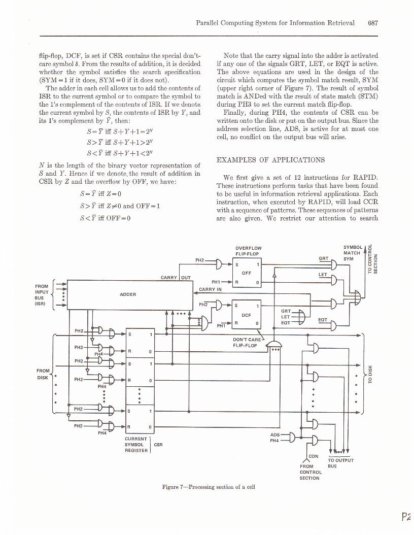
Parallel Computing System for Information Retrieval 687
flip-flop, DCF, is set if CSR contains the special don't-care symbol o. From the results of addition, it is decidedwhether the symbol satisfies the search specification(SYM = 1 if it does, SYM = 0 if it does not).The adder in each cell allows us to add the contents of
ISR to the current symbol or to compare the symbol tothe l's complement of the contents of ISR. If we denotsthe current symbol by S, the contents of ISR by Y, andits l's complement by Y, then:
S = Y iff S+Y+1= 2N
S> Y iff S+Y+1> 2N
S<Y iff S+Y+1<2N
N is the length of the binary vector representation ofSand Y. Hence if we denote, the result of addition inCSR by Z and the overflow by OFF, we have:
S= Y iff Z=O
S> Y iff Z~O and OFF= 1
S< Y iff OFF=O
'"OM {INPUTBUS(lSR)
PH2
PH2
PH2
FROM
DISK • PH2•••
PH2
PH2
ADDER
R
...
Note that the carry signal into the adder is activatedif anyone of the signals GRT, LET, or EQT is active.The above equations are used in the design of thecircuit which computes the symbol match result, SYM(upper right corner of Figure 7). The result of symbolmatch is ANDed with the result of state match (STM)during PH3 to set the current match flip-flop.Finally, during PH4, the contents of CSR can be
written onto the disk or put on the output bus. Since theaddress selection line, ADS, is active for at most onecell, no conflict on the output bus will arise.
EXAMPLES OF APPLICATIONS
We first give a set of 12 instructions for RAPID.These instructions perform tasks that have been foundto be useful in information retrieval applications. Eachinstruction, when executed by RAPID, will load CCRwith a sequence of patterns. These sequences of patternsare also given. We restrict our attention to search
OVERFLOWFLIP-FLOP
SYMBOLMATCH
-'oa:1-2200-ul-o~I-en
S ~enCioI-Or--------+--------------------~
•••
Or-------------------------------JCURRENT ISYMBOL CSRREGISTER
Figure 7-Processing section of a cell
FROM BUSCONTROLSECTION

688 Fall Joint Computer Conference, 1972
instructions only. Input and output instructions mustalso be provided to complete the set.
1. search and set s: Find all occurrences of thesymbol s and set their states.
2. search for SlS2 ••• Sn: Find all the occurrences ofthe string SlS2 ••• Sn and set the state of thesymbols which immediately follow Sn.
3. search for lllarked SlS2 .•. Sn: Same as theprevious instruction except that for a string toqualify, the state of its first symbol must be set.
4. search for lllarked if; s: Search for symbolswhose states are set and have the relation if; withs. Then, set the state of the following symbol.Possible relations are <, S, >, ?:, and ~.
5. propagate to s: If the state of a symbol is set,reset it and set the state of the first S followingit.
6. propagatei: If the state of a symbol is set,
reset it and set the state of the i-th symbol to itsright.
7. expand to s: If the state of a symbol is set, setthe state of all symbols following it up to andincluding the first occurrence of s.
8. expand i: If the state of a symbol is set, set thestate of the first i symbols following it.
9. contract i: If the state of a symbol is reset,reset the state of the first i symbols following it.
10. expand i or to s: If the state of a symbol is set,perform 7 if an S appears within the next isymbols; otherwise, perform 8.
11. add s: Add the numerical value of s to thenumerical value of any symbol whose state is set.
12. replace by s: If the state of a symbol is set,replace the symbol by s.
TABLE III-Microprograms for RAPID Instructions
The microprograms for these instructions are given
Contents of CCR
c Match Field Condition Field0 VIa: Read Write Address~ .•••Vl.•.. c •..• Field Field Selection FF Selection~ ell State Symbol ogicL. .•.. .•...•..ell Instruction ell co.a Q. 0 R R W W L If M M G L E L -S- S S S!! ell Ua: S S S S A A S S R E Q 0 C A C Pz
T y T Y S S 1 Z T T T F S S M M1 search and set s 1 S 1 1 0 0 1 1 0 0 1 0 0 1 0
1 sl 1 1 0 0 1 1 0 0 1 0 0 0 12 search for sls2 •.• sn
1 1 1 0 0 1 0 0 0 1 0 0 0 1j=2 to n si
3 search for marked sls2 .•• sn j=l to n si 1 1 1 0 0 1 0 0 0 1 0 0 0 1
< 1 S 1 1 1 0 0 1 0 0 1 0 0 0 0 1
s 1 S 1 1 1 0 0 1 0 0 1 1 0 0 0 1
> 1 S 1 1 1 0 0 1 0 1 0 0 0 0 0 14 ~arch for marked ~s
~ 1 S 1 1 1 0 0 1 0 1 0 1 0 0 0 1
" 1 S 1 1 1 0 0 1 0 1 1 0 0 0 0 1
5 er~e.a~ate t.,2 s 1 S 1 1 1 0 0 1 1 1 0 0 1 1 0 1 1 0
6 eroEa2a~ i i 1 1 0 0 1 0 1 1 1 0 0 0 1
7 exeand to s 1 S 1 1 1 0 0 1 1 1 0 0 1 0 1 0 0
8 eXBa.nd i f 1 1 0 0 1 0 1 1 1 0 1 0 0 1
9 contract i i 1 1 0 0 1 0 1 1 1 1 1 0 0 1
S 1 1 1 0 0 1 1 1 1 0 1 1 0 1 010 exeand f ~s i
0 11 1 0 0 1 0 1 1 1 0 1 0
11 add s 1 s 1 1 1 0 1 0 0 0-12 reJ!li1~e bl 1 s 1 0 1 0 1 0 0 0s

Parallel Computing System for Information Retrieval 689
RECORDLENGTHFIELD
RECORD RECORDTYPe: FLAG·E EMPTYV NON-EMPTY
ENDSYMBOL
NAME
FIELDINFORMATION
SEPARATORSYMBOL
FIELDENDSYMBOL
Figure 8-Data storage format
in Table III. A blank entry in this table constitutes adon't-care condition. The entries in the repetitioncolumn specify the number of times the given patternsshould be repeated. As can be seen from Table III, thisset of instructions does not exploit all the capabilities ofRAPID since some of the bits in the CCR assume onlyone value (0 or 1) for all the instructions.To illustrate the applications of RAPID, we first
choose a format for the records (Figure 8). The recordlength field must have a fixed length in order to allowsymbol by symbol comparison of the record length to agiven number. The information fields can be of arbitrarylengths. The flag field contains three characters; two forholding the results of searches, and one which containsa record type flag. The Greek letters used on Figure 8are reserved symbols and should not be used except forthe purposes given in Table IV.As mentioned earlier, a special symbol, 0, is used as a
don't-care symbol. It is also helpful to have a reservedsymbol, T, which can be used as temporary substitutefor other symbols during a search operation. Let us nowconsider two simple examples to show the utility of thegiven instruction set.Example 1. Assuming that the record length is
specified by one symbol, the following program marksall the empty records whose lengths are not less than 8.
This is useful when entering a new record of length 8 tofind which tracks contain empty records that are largeenough.
search for Asearch for marked :2: 8
propagate to ppropagate 3search for marked E
If the record length is specified by two characters, wenote that t1t2:2: 8182 iff t1> 81 or t1= 81 and t2:2: 82. Hence,we write the following program:
search for Asearch for marked > 81
propagate 1replace by T
search for Asearch for marked 81
search for marked :2: 82
replace by T
search and set T
replace by cppropagate to ppropagate 3search for marked E
Example 2. The following program marks all non-empty records which contain in their title field,designated by TI, a word having "magnet" as its firstsix characters and having 3 to 10 non-blank charactersafter that. {3 designates the "blank" character.
search for cpTla-expand to cpsearch for marked magnetexpand 10or to {3contract 3propaga te to ppropagate 3search for marked II
It is important to note that the record format givenhere serves only as illustration. Because of its generalityand flexibility, this format is not very efficient in termsof storage overhead and processing speed. For any givenapplication, one can probably design a format which ismore efficient for the types of queries involved.
CONCLUSION
In this paper, we have described a special-purposehighly parallel system for information retrieval applica-
TABLE IV-List of Reserved Symbols
x Indicates start of length field.p Indicates end of a record.(J' Separates name and information subfields in a field.</> Indicates end of a field.
Designates the end of an empty record.p Designates the end of a non-empty record.a Is the don't-care symbol.'T Is used as temporary substitute for other symbols.
pz

690 Fall Joint Computer Conference, 1972
tions. This system must be evaluated with respect to theproperties of an ideal information retrieval systemsummarized earlier. It is apparent that RAPID satisfiesP2, P4 and P5. The extent to which PI and P3 aresatisfied by RAPID is difficult to estimate at thepresent.With respect to P1, the storage medium used has a low
cost per bit. However, the cost for cells must also beconsidered. Because of the large number of identicalcells required, economical implementation with LSI ispossible. Figures 6 and 7 show that each cell has oneN-bit adder, N +6 flip-flops, 6N +39 gates, and 4N +23input and output pins. For a symbol length of N = 8bits, each cell will require no more than 250 gates and 60input and output pins. The number of input and outputpins can be reduced considerably at the expense of moresophisticated gating circuits (i.e., sharing input andoutput connections).With respect to P3, the search speed depends on the
number of symbols matched. If we assume that on theaverage 50 symbols are matched, the matching phasewill take about 70 disk revolutions (to allow foroverhead such as propagation of state information andperformance of logical operations on the search results).Hence, the search time for marking the tracks whichcontain relevant information is of the order of a fewseconds.Some important considerations such as input and
output of data and fault-tolerance in RAPID have notbeen explored in detail and constitute possible areas forfuture research. The interested reader may consultReference 12 for some thoughts on these topics.
ACKNOWLEDGMENTS
The author gratefully acknowledges the guidance andencouragement given by Dr. W. W. Chu in the courseof this study. Thanks are also due to Messrs. P. Chang,D. Patterson, and R. Weeks for stimulating discus-sions.
REFERENCES
1 J GOLDBERG M W GREENLarge files for information retrieval based on simultaneousinterrogation of all itemsLarge-capacity Memory Techniques for Computing SystemsNew York Macmillan pp 63-67 1962
2 S S YAU C C YANGA cryogenic associative memory system for informationretrievalProceedings of the National Electronics Conference pp764-769 October 1966
3 J A DUGAN R S GREEN J MINKERWE SHINDLEA study of the utility of associative memory processorsProceedings of the ACM National Conference pp 347-360August 1966
4CYLEEIntercommunicating cells, basis for a distributed-logic computerProceedings of the FJCC pp 130-136 1962
5 C Y LEE M C PAULLA content-addressable distributed-logic memory withapplications to information retrievalProceedings of the IEEE Vol 51 pp 924-932 June 1963
6 D A SAVITT H H LOVE R E TROOPASP; a new concept in language and machine organizationProceedings of the SJCC pp 87-102 1967
7 W A CROFUT M R SOTTILEDesign techniques of a delay line content-addressed memoryIEEE Transactions on Electronic Computers Vol EC-15pp 529-534 August 1966
8 P T RUXA glass delay line content-addressable memory systemIEEE Transactions on Computers Vol C-18 pp 512-520June 1969
9 R H FULLER R M BIRD R M WORTHYStudy of associative processing techniquesDefense Documentation Center AD-621516 August 1965
10 D L SLOTNICKLogic per track devicesAdvances in Computers Vol 10 pp 291-296 New YorkAcademic Press 1970
11 J L PARKERA logic-per-track retrieval systemProceedings of the IFIPS Conference pp TA-4-146 toTA-4-150 1971
12 B PARHAM IRAPID; a rotating associative processor for informationdisseminationTechnical Report UCLA-ENG-7213 University of Cali-fornia at Los Angeles February 1972