Embed Size (px)
Citation preview
AgSense™ Manual

AgSense User Guide 2012 Page 2
AgSense, LLC
259 Dakota Ave S
Huron, SD 57350
Phone (605)352-8350 ∙ Fax (605)352-8351
http://www.agsense.net
AgSense™ Manual
AgSense User Guide 2012 Page 3
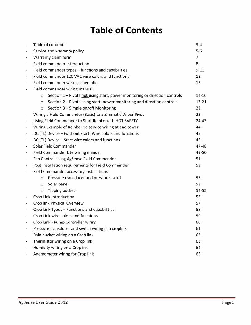
Table of Contents
- Table of contents 3-4
- Service and warranty policy 5-6
- Warranty claim form 7
- Field commander introduction 8
- Field commander types – functions and capabilities 9-11
- Field commander 120 VAC wire colors and functions 12
- Field commander wiring schematic 13
- Field commander wiring manual
o Section 1 – Pivots not using start, power monitoring or direction controls 14-16
o Section 2 – Pivots using start, power monitoring and direction controls 17-21
o Section 3 – Simple on/off Monitoring 22
- Wiring a Field Commander (Basic) to a Zimmatic Wiper Pivot 23
- Using Field Commander to Start Reinke with HOT SAFETY 24-43
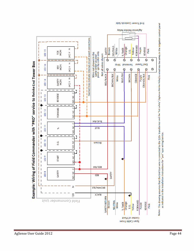
- Wiring Example of Reinke Pro service wiring at end tower 44
- DC (TL) Device – (without start) Wire colors and functions 45
- DC (TL) Device – Start wire colors and functions 46
- Solar Field Commander 47-48
- Field Commander Lite wiring manual 49-50
- Fan Control Using AgSense Field Commander 51
- Post Installation requirements for Field Commander 52
- Field Commander accessory installations
o Pressure transducer and pressure switch 53
o Solar panel 53
o Tipping bucket 54-55
- Crop Link Introduction 56
- Crop link Physical Overview 57
- Crop Link Types – Functions and Capabilities 58
- Crop Link wire colors and functions 59
- Crop Link - Pump Controller wiring 60
- Pressure transducer and switch wiring in a croplink 61
- Rain bucket wiring on a Crop link 62
- Thermistor wiring on a Crop link 63
- Humidity wiring on a Croplink 64
- Anemometer wiring for Crop link 65
AgSense User Guide 2012 Page 4
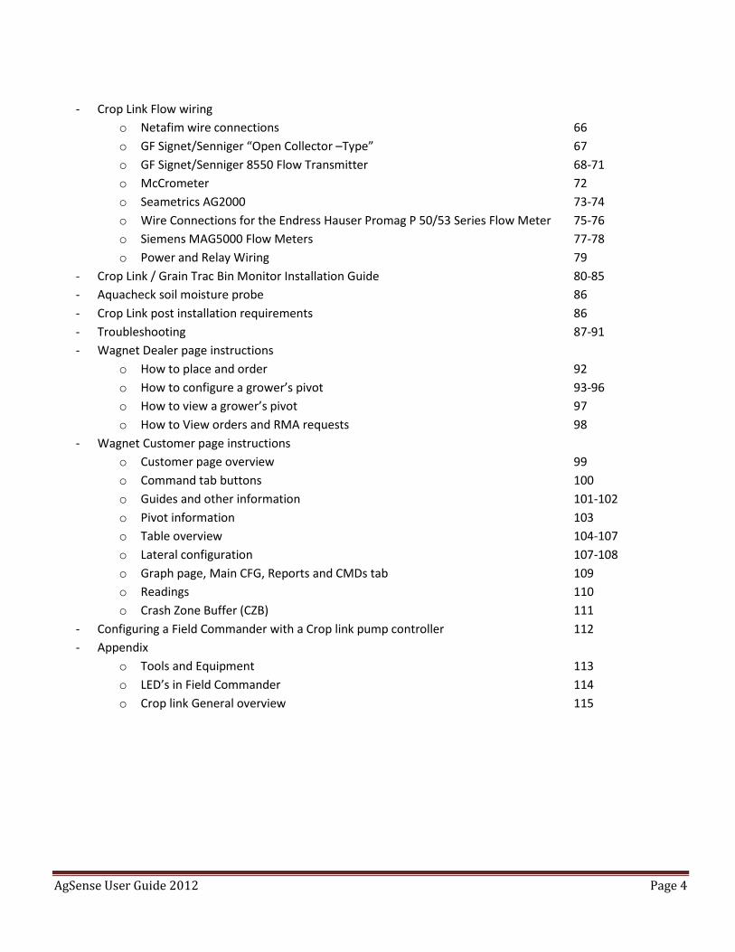
- Crop Link Flow wiring
o Netafim wire connections 66
o GF Signet/Senniger “Open Collector –Type” 67
o GF Signet/Senniger 8550 Flow Transmitter 68-71
o McCrometer 72
o Seametrics AG2000 73-74
o Wire Connections for the Endress Hauser Promag P 50/53 Series Flow Meter 75-76
o Siemens MAG5000 Flow Meters 77-78
o Power and Relay Wiring 79
- Crop Link / Grain Trac Bin Monitor Installation Guide 80-85
- Aquacheck soil moisture probe 86
- Crop Link post installation requirements 86
- Troubleshooting 87-91
- Wagnet Dealer page instructions
o How to place and order 92
o How to configure a grower’s pivot 93-96
o How to view a grower’s pivot 97
o How to View orders and RMA requests 98
- Wagnet Customer page instructions
o Customer page overview 99
o Command tab buttons 100
o Guides and other information 101-102
o Pivot information 103
o Table overview 104-107
o Lateral configuration 107-108
o Graph page, Main CFG, Reports and CMDs tab 109
o Readings 110
o Crash Zone Buffer (CZB) 111
- Configuring a Field Commander with a Crop link pump controller 112
- Appendix
o Tools and Equipment 113
o LED’s in Field Commander 114
o Crop link General overview 115
AgSense User Guide 2012 Page 5
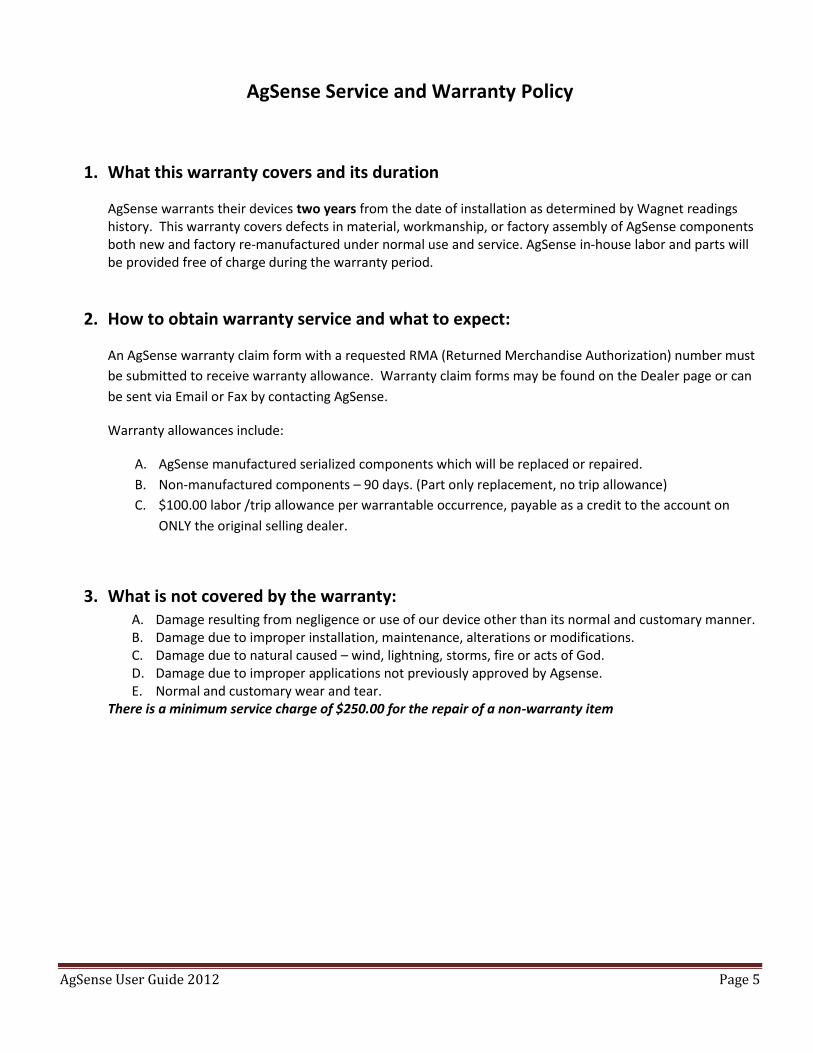
AgSense Service and Warranty Policy
1. What this warranty covers and its duration
AgSense warrants their devices two years from the date of installation as determined by Wagnet readings history. This warranty covers defects in material, workmanship, or factory assembly of AgSense components both new and factory re-manufactured under normal use and service. AgSense in-house labor and parts will be provided free of charge during the warranty period.
2. How to obtain warranty service and what to expect:
An AgSense warranty claim form with a requested RMA (Returned Merchandise Authorization) number must
be submitted to receive warranty allowance. Warranty claim forms may be found on the Dealer page or can
be sent via Email or Fax by contacting AgSense.
Warranty allowances include:
A. AgSense manufactured serialized components which will be replaced or repaired.
B. Non-manufactured components – 90 days. (Part only replacement, no trip allowance)
C. $100.00 labor /trip allowance per warrantable occurrence, payable as a credit to the account on
ONLY the original selling dealer.
3. What is not covered by the warranty: A. Damage resulting from negligence or use of our device other than its normal and customary manner. B. Damage due to improper installation, maintenance, alterations or modifications. C. Damage due to natural caused – wind, lightning, storms, fire or acts of God. D. Damage due to improper applications not previously approved by Agsense. E. Normal and customary wear and tear.
There is a minimum service charge of $250.00 for the repair of a non-warranty item
AgSense User Guide 2012 Page 6
Exclusion of implied warranties – Your sole and exclusive remedy is product repair or replace as provided in this Limited Warranty. Any implied warranties, including the implied warranties of merchantability or fitness for a particular purpose, are limited to two years or the shortest period allowed by law. This warranty is extended to the original purchaser and any succeeding owner for the products purchased for use within the USA. Some states do not allow the exclusion or limitation of incidental or consequential damages. This warranty gives you specific legal rights, and you may also have other rights which vary from state to state. To know what your legal rights are, consult your local or state consumer affairs office or your state’s Attorney General. DISCLAIMER: The use of Field Commander/Crop Link/Aqua Trac shall not be utilized by customer as a substitute for the Customer's personal observation of the manner in which Customer's irrigation equipment is functioning. AgSense specifically advises Customer that this product is designed to enhance Customer's ability to control existing irrigation equipment and to provide the Customer with additional information about existing irrigation equipment. Field Commander/Crop Link/Aqua Trac relies upon GPS, Satellite and Internet technology which not always functions properly; accordingly, AgSense disclaims any and all responsibility for the reliability of this technology. Customer acknowledges that AgSense does not have the ability to control the reliability of GPS, Satellite and Internet Technology. AgSense specifically disclaims any and all liability for Customer's failure to personally determine whether or not the irrigation equipment that belongs to Customer is functioning properly. AgSense, its agents, members or officers will not be liable for Customer's loss of profits, business interruption, or any other type of consequential damages arising because of the failure to Customer's equipment, GPS, Satellite or Internet to function properly. CUSTOMER'S RESPONSIBILITIES: Customer agrees to keep the irrigation equipment upon which Field Commander/Crop Link/Aqua Trac is installed in good repair and maintenance. Customer acknowledges the importance of and agrees to keep all safety devices which came with Customer's irrigation equipment in working order. Customer agrees to keep an end field stop and barricades in place to prevent damage to the irrigation equipment in the event that Field Commander/Crop Link/Aqua Trac malfunctions. Customer agrees that Field Commander/Crop Link/Aqua Trac cannot solely replace the personal monitoring of the operation of irrigation equipment. REMEDY: Customer acknowledges that Field Commander/Crop Link/Aqua Trac’s sole obligation and Customer's exclusive remedy in the event of any material and continuing nonconformity, defect, or error in the information service shall be to take reasonable corrective actions upon discovery of the problem.
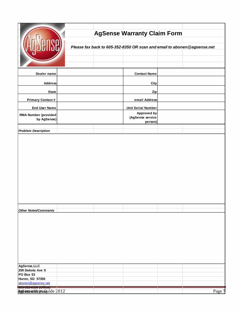
AgSense User Guide 2012 Page 7
Dealer name Contact Name
Address City
State Zip
Primary Contact # email Address
End User Name Unit Serial Number
RMA Number (provided
by AgSense)
Approved by
(AgSense service
person)
Problem Description
Other Notes/Comments
AgSense,LLC
259 Dakota Ave S
PO Box 53
Huron, SD 57350
605-352-8350 (Office)
605-352-8351 (Fax)
AgSense Warranty Claim Form
Please fax back to 605-352-8350 OR scan and email to [email protected]

AgSense User Guide 2012 Page 8
Field Commander Introduction
Field Commander is an advanced GPS driven pivot monitor and control system that communicates via the digital cell
network to provide new real-time information and up to the minute alarms to your cell phone, smart phone or
computer. The Field commander provides:
- State-of-the-art patented technology.
- Expandable applications to allow the monitoring of flow meters, pumps, weather sensors, and soil moisture
probes.
- Incorporation of future developing applications.
- Time and expense saving techniques by checking and controlling pivots from your home computer or smart
phone.
- Flexibility so it can be used on all brands and vintages of pivots and panels.
- Efficient and reliable remote implementation of your irrigation prescriptions.
Wagnet’ s revolutionary micro-network technology enables the Field Commander to communicate with multiple
sensors, meters and pumps in the field via the Crop Link remote telemetry unit (RTU).
Some of the Field Commanders features and functions are dependent upon the capability of the pivot and its panel.
AgSense User Guide 2012 Page 9
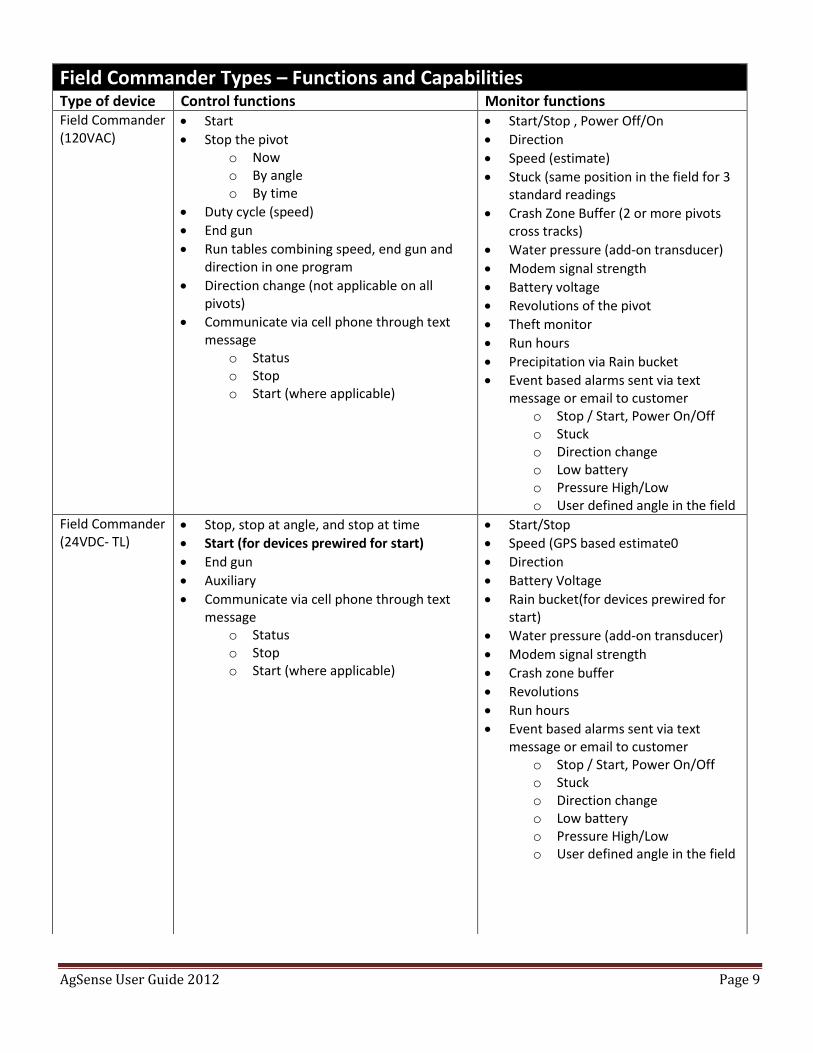
Field Commander Types – Functions and Capabilities
Type of device Control functions Monitor functions Field Commander (120VAC)
Start
Stop the pivot o Now o By angle o By time
Duty cycle (speed)
End gun
Run tables combining speed, end gun and direction in one program
Direction change (not applicable on all pivots)
Communicate via cell phone through text message
o Status o Stop o Start (where applicable)
Start/Stop , Power Off/On
Direction
Speed (estimate)
Stuck (same position in the field for 3 standard readings
Crash Zone Buffer (2 or more pivots cross tracks)
Water pressure (add-on transducer)
Modem signal strength
Battery voltage
Revolutions of the pivot
Theft monitor
Run hours
Precipitation via Rain bucket
Event based alarms sent via text message or email to customer
o Stop / Start, Power On/Off o Stuck o Direction change o Low battery o Pressure High/Low o User defined angle in the field
Field Commander (24VDC- TL)
Stop, stop at angle, and stop at time
Start (for devices prewired for start)
End gun
Auxiliary
Communicate via cell phone through text message
o Status o Stop o Start (where applicable)
Start/Stop
Speed (GPS based estimate0
Direction
Battery Voltage
Rain bucket(for devices prewired for start)
Water pressure (add-on transducer)
Modem signal strength
Crash zone buffer
Revolutions
Run hours
Event based alarms sent via text message or email to customer
o Stop / Start, Power On/Off o Stuck o Direction change o Low battery o Pressure High/Low o User defined angle in the field
AgSense User Guide 2012 Page 10
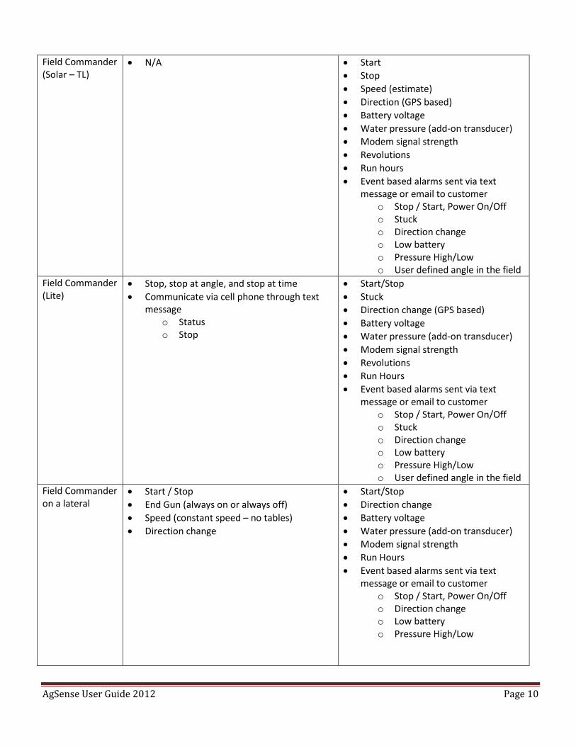
Field Commander (Solar – TL)
N/A Start
Stop
Speed (estimate)
Direction (GPS based)
Battery voltage
Water pressure (add-on transducer)
Modem signal strength
Revolutions
Run hours
Event based alarms sent via text message or email to customer
o Stop / Start, Power On/Off o Stuck o Direction change o Low battery o Pressure High/Low o User defined angle in the field
Field Commander (Lite)
Stop, stop at angle, and stop at time
Communicate via cell phone through text message
o Status o Stop
Start/Stop
Stuck
Direction change (GPS based)
Battery voltage
Water pressure (add-on transducer)
Modem signal strength
Revolutions
Run Hours
Event based alarms sent via text message or email to customer
o Stop / Start, Power On/Off o Stuck o Direction change o Low battery o Pressure High/Low o User defined angle in the field
Field Commander on a lateral
Start / Stop
End Gun (always on or always off)
Speed (constant speed – no tables)
Direction change
Start/Stop
Direction change
Battery voltage
Water pressure (add-on transducer)
Modem signal strength
Run Hours
Event based alarms sent via text message or email to customer
o Stop / Start, Power On/Off o Direction change o Low battery o Pressure High/Low
AgSense User Guide 2012 Page 11
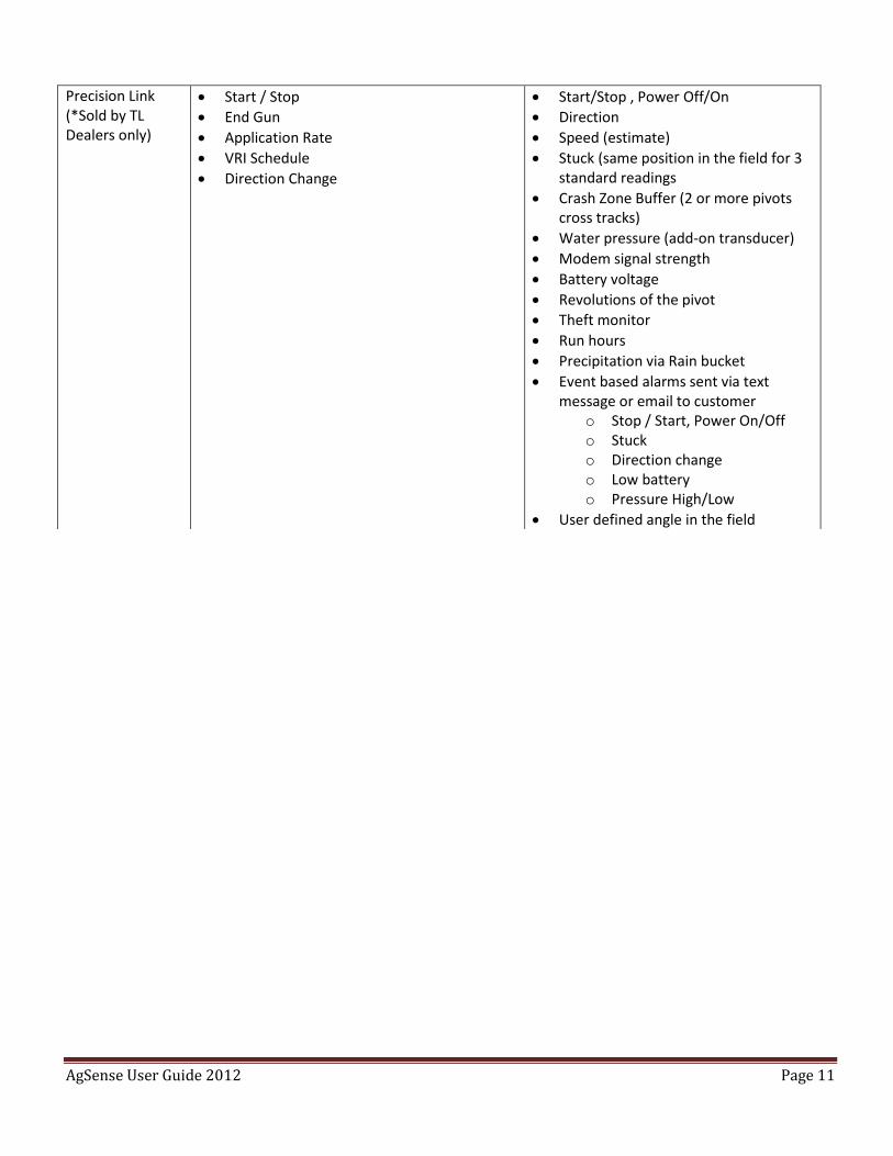
Precision Link (*Sold by TL Dealers only)
Start / Stop
End Gun
Application Rate
VRI Schedule
Direction Change
Start/Stop , Power Off/On
Direction
Speed (estimate)
Stuck (same position in the field for 3 standard readings
Crash Zone Buffer (2 or more pivots cross tracks)
Water pressure (add-on transducer)
Modem signal strength
Battery voltage
Revolutions of the pivot
Theft monitor
Run hours
Precipitation via Rain bucket
Event based alarms sent via text message or email to customer
o Stop / Start, Power On/Off o Stuck o Direction change o Low battery o Pressure High/Low
User defined angle in the field
AgSense User Guide 2012 Page 12
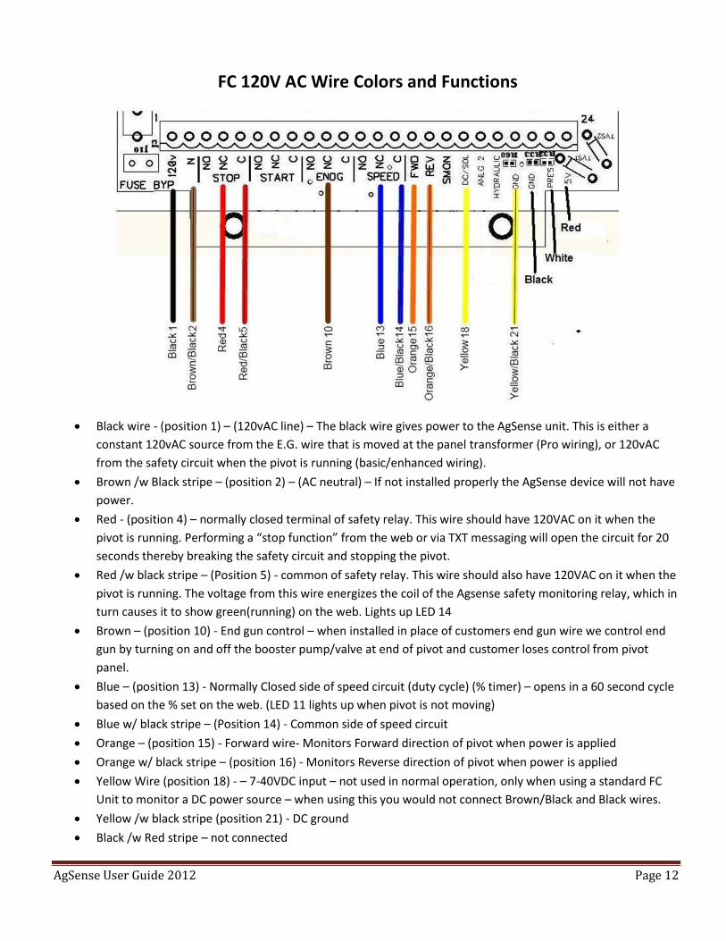
FC 120V AC Wire Colors and Functions
Black wire - (position 1) – (120vAC line) – The black wire gives power to the AgSense unit. This is either a
constant 120vAC source from the E.G. wire that is moved at the panel transformer (Pro wiring), or 120vAC
from the safety circuit when the pivot is running (basic/enhanced wiring).
Brown /w Black stripe – (position 2) – (AC neutral) – If not installed properly the AgSense device will not have
power.
Red - (position 4) – normally closed terminal of safety relay. This wire should have 120VAC on it when the
pivot is running. Performing a “stop function” from the web or via TXT messaging will open the circuit for 20
seconds thereby breaking the safety circuit and stopping the pivot.
Red /w black stripe – (Position 5) - common of safety relay. This wire should also have 120VAC on it when the
pivot is running. The voltage from this wire energizes the coil of the Agsense safety monitoring relay, which in
turn causes it to show green(running) on the web. Lights up LED 14
Brown – (position 10) - End gun control – when installed in place of customers end gun wire we control end
gun by turning on and off the booster pump/valve at end of pivot and customer loses control from pivot
panel.
Blue – (position 13) - Normally Closed side of speed circuit (duty cycle) (% timer) – opens in a 60 second cycle
based on the % set on the web. (LED 11 lights up when pivot is not moving)
Blue w/ black stripe – (Position 14) - Common side of speed circuit
Orange – (position 15) - Forward wire- Monitors Forward direction of pivot when power is applied
Orange w/ black stripe – (position 16) - Monitors Reverse direction of pivot when power is applied
Yellow Wire (position 18) - – 7-40VDC input – not used in normal operation, only when using a standard FC
Unit to monitor a DC power source – when using this you would not connect Brown/Black and Black wires.
Yellow /w black stripe (position 21) - DC ground
Black /w Red stripe – not connected
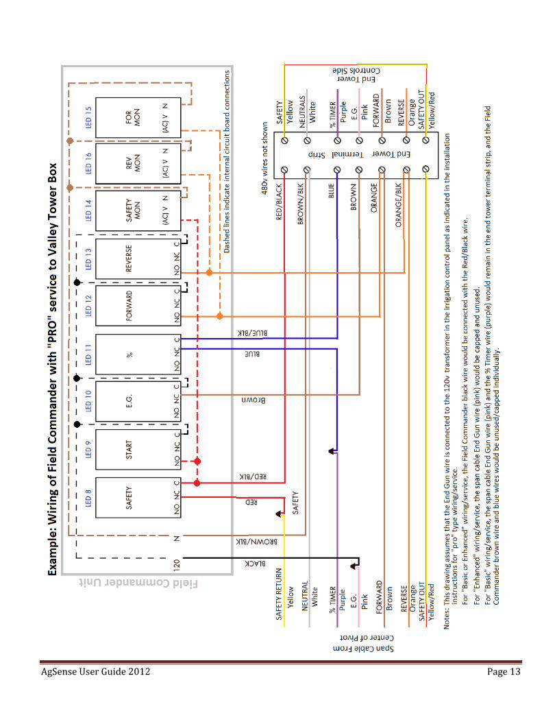
AgSense User Guide 2012 Page 13
AgSense User Guide 2012 Page 14
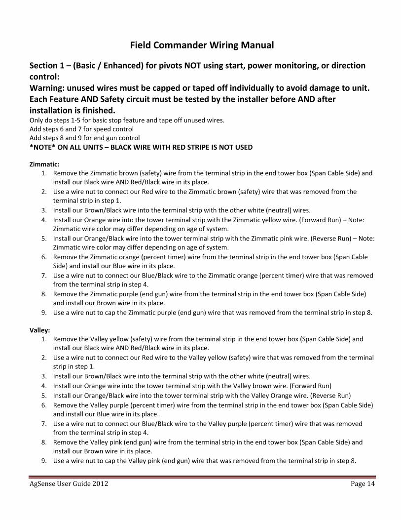
Field Commander Wiring Manual
Section 1 – (Basic / Enhanced) for pivots NOT using start, power monitoring, or direction control: Warning: unused wires must be capped or taped off individually to avoid damage to unit. Each Feature AND Safety circuit must be tested by the installer before AND after installation is finished. Only do steps 1-5 for basic stop feature and tape off unused wires. Add steps 6 and 7 for speed control Add steps 8 and 9 for end gun control
*NOTE* ON ALL UNITS – BLACK WIRE WITH RED STRIPE IS NOT USED
Zimmatic: 1. Remove the Zimmatic brown (safety) wire from the terminal strip in the end tower box (Span Cable Side) and
install our Black wire AND Red/Black wire in its place.
2. Use a wire nut to connect our Red wire to the Zimmatic brown (safety) wire that was removed from the terminal strip in step 1.
3. Install our Brown/Black wire into the terminal strip with the other white (neutral) wires.
4. Install our Orange wire into the tower terminal strip with the Zimmatic yellow wire. (Forward Run) – Note: Zimmatic wire color may differ depending on age of system.
5. Install our Orange/Black wire into the tower terminal strip with the Zimmatic pink wire. (Reverse Run) – Note: Zimmatic wire color may differ depending on age of system.
6. Remove the Zimmatic orange (percent timer) wire from the terminal strip in the end tower box (Span Cable Side) and install our Blue wire in its place.
7. Use a wire nut to connect our Blue/Black wire to the Zimmatic orange (percent timer) wire that was removed from the terminal strip in step 4.
8. Remove the Zimmatic purple (end gun) wire from the terminal strip in the end tower box (Span Cable Side) and install our Brown wire in its place.
9. Use a wire nut to cap the Zimmatic purple (end gun) wire that was removed from the terminal strip in step 8. Valley:
1. Remove the Valley yellow (safety) wire from the terminal strip in the end tower box (Span Cable Side) and install our Black wire AND Red/Black wire in its place.
2. Use a wire nut to connect our Red wire to the Valley yellow (safety) wire that was removed from the terminal strip in step 1.
3. Install our Brown/Black wire into the terminal strip with the other white (neutral) wires.
4. Install our Orange wire into the tower terminal strip with the Valley brown wire. (Forward Run)
5. Install our Orange/Black wire into the tower terminal strip with the Valley Orange wire. (Reverse Run)
6. Remove the Valley purple (percent timer) wire from the terminal strip in the end tower box (Span Cable Side) and install our Blue wire in its place.
7. Use a wire nut to connect our Blue/Black wire to the Valley purple (percent timer) wire that was removed from the terminal strip in step 4.
8. Remove the Valley pink (end gun) wire from the terminal strip in the end tower box (Span Cable Side) and install our Brown wire in its place.
9. Use a wire nut to cap the Valley pink (end gun) wire that was removed from the terminal strip in step 8.
AgSense User Guide 2012 Page 15
Pierce (Newer systems, example - CP600 pivots):
1. Remove the Pierce yellow (safety) wire from the terminal strip in the end tower box (Span cable wire coming from the center) and install our Black wire AND Red/Black wire in its place.
2. Use a wire nut to connect our Red wire to the Pierce yellow (safety) wire that was removed from the terminal strip in step 1.
3. Install our Brown/Black wire into the terminal strip with the other white (neutral) wires. 4. Install our Orange wire into the tower terminal strip with the Pierce brown wire. (Forward Run) 5. Install our Orange/Black wire into the tower terminal strip with the Pierce Orange wire. (Reverse Run) 6. Remove the Pierce purple (percent timer) wire from the terminal strip in the end tower box (Span cable wire
coming from the center) and install our Blue wire in its place. 7. Use a wire nut to connect our Blue/Black wire to the Pierce purple (percent timer) wire that was removed
from the terminal strip in step 6. 8. Remove the Pierce pink (end gun) wire from the terminal strip in the end tower box (Span cable wire coming
from the center) and install our Brown wire in its place. 9. Use a wire nut to cap the Pierce pink (end gun) wire that was removed from the terminal strip in step 8.
Pierce (Older systems, example - P.93 pivots):
1. Remove the Pierce brown (safety) wire from the terminal strip in the end tower box (Span cable wire coming from the center) and install our Black wire AND Red/Black wire in its place.
2. Use a wire nut to connect our Red wire to the Pierce brown (safety) wire that was removed from the terminal strip in step 1.
3. Install our Brown/Black wire into the terminal strip with the other white (neutral) wires. 4. Install our Orange wire into the tower terminal strip with the Pierce purple wire. (Forward Run) 5. Install our Orange/Black wire into the tower terminal strip with the Pierce yellow wire. (Reverse Run) 6. Remove the Pierce orange (percent timer) wire from the terminal strip in the end tower box (Span cable wire
coming from the center) and install our Blue wire in its place. 7. Use a wire nut to connect our Blue/Black wire to the Pierce orange (percent timer) wire that was removed
from the terminal strip in step 6. 8. Remove the Pierce tan (end gun) wire from the terminal strip in the end tower box (Span cable wire coming
from the center) and install our Brown wire in its place. 9. Use a wire nut to cap the Pierce tan (end gun) wire that was removed from the terminal strip in step 8.
Olson: (After 1980)
1. Remove the yellow (safety) wire from the terminal strip in the end tower box (Span Cable Side) and install our Black wire AND Red/Black wire in its place.
2. Use a wire nut to connect our Red wire to the yellow (safety) wire that was removed from the terminal strip in step 1.
3. Install our Brown/Black wire into the terminal strip with the other white (neutral) wires.
4. Install our Orange wire into the tower terminal strip with the Olson brown wire. (Forward Run)
5. Install our Orange/Black wire into the tower terminal strip with the Olson white/black wire. (Reverse Run)
6. Remove the Olson grey (percent timer) wire from the terminal strip in the end tower box (Span Cable Side) and install our Blue wire in its place.
7. Use a wire nut to connect our Blue/Black wire to the Olson grey (percent timer) wire that was removed from the terminal strip in step 4
8. Remove the Olson purple (end gun) wire from the terminal strip in the end tower box (Span Cable Side) and install our Brown wire in its place.
9. Use a wire
AgSense User Guide 2012 Page 16
Lockwood with 16v safety system:
1. Remove the 120v wire going to the safety transformer and connect our Black wire AND Red/Black wire in its place.
2. Use a wire nut to connect our Red wire to the wire that was removed from the transformer in step 1.
3. Install our Brown/Black wire in with the other neutral (white) wires. -see note-
4. Install our Orange wire into the tower terminal strip with the Lockwood yellow wire. (Forward Run)
5. Install our Orange/Black wire into the tower terminal strip with the Lockwood orange wire. (Reverse Run)
6. Remove the Lockwood purple (percent timer) wire from the terminal strip in the end tower box and install our Blue wire in its place.
7. Use a wire nut to connect our Blue/Black wire to the Lockwood purple (percent timer) wire that was removed from the terminal strip in step 4.
8. Remove the Lockwood brown (end gun) wire from the terminal strip in the end tower box and install our Brown wire in its place.
9. Use a wire nut to cap the Lockwood brown (end gun) wire that was removed from the terminal strip in step 8. -Note- on older Lockwood systems, the power to the safety transformer is flip-flopped depending on which direction the system is moving. On these, change step 3 to this: Install our Brown/Black wire into the other 120v terminal on the safety transformer. (With the wire that was not disturbed in step 1 or 2) -With the unit wired this way, the Field Commander end gun control may only work in one direction-
AgSense User Guide 2012 Page 17
Section 2 – (Pro) Start, Power Monitoring and Direction control wiring: For pivots using Start, Power Monitoring, or Direction Control: Warning: unused wires must be capped or taped off individually to avoid damage to unit. Each Feature AND Safety circuit must be tested by the installer before AND after installation is finished. Start Feature applies 120v to the safety circuit for 10 seconds to start the pivot – this may not work on all pivots to be able to start the pivot. Example: start works well on most Valley pivots, Zimmatic, and various others. In the Pivot Control Panel, remove end gun wire that goes out to the tower boxes and connect it to 120v at the transformer. Also, remove any end gun stops/ramps/shutoffs. (End gun wire will have 120v at all times) Direction Control will not work on all pivots! The direction control works by applying 120v to the wire opposite of the direction the pivot is currently moving for 10 seconds. – this will not work on all pivots and MUST be tested by the installer before adding this feature - Simply test by using a fused jumper wire to connect 120v to the direction wire opposite the direction the pivot is currently moving for 10 seconds. Test this for both directions. If the pivot changes direction and stays moving that direction, then proceed with adding this feature. Perform steps 1 - 3 and 6 – 9 and cap off unused wires. Add steps 4 – 5 for speed control
*NOTE* ON ALL UNITS – BLACK WIRE WITH RED STRIPE IS NOT USED
Zimmatic: (Read beginning of Section 2 before proceeding) 1. Remove the Zimmatic brown (safety) wire from the terminal strip in the end tower box (Span Cable Side) and
install our Red/Black wire in its place.
2. Use a wire nut to connect our Red wire to the Zimmatic brown (safety) wire that was removed from the terminal strip in step 1.
3. Install our Brown/Black wire into the terminal strip with the other white (neutral) wires.
4. Remove the Zimmatic orange (percent timer) wire from the terminal strip in the end tower box (Span Cable Side) and install our Blue wire in its place.
5. Use a wire nut to connect our Blue/Black wire to the Zimmatic orange (percent timer) wire that was removed from the terminal strip in step 4.
6. Remove the Zimmatic purple (end gun) wire from the terminal strip in the end tower box (Span Cable Side) and install our Brown wire in its place.
7. Use a wire nut to connect our Black wire to the Zimmatic purple (end gun wire coming from the control panel (120v all the time)) wire that was removed from the terminal strip in step 6.
8. Install our Orange wire into the tower terminal strip with the Zimmatic yellow wire. (Forward Run) – Note: Zimmatic wire color may differ depending on age of system.
9. Install our Orange/Black wire into the tower terminal strip with the Zimmatic pink wire. (Reverse Run) – Note: Zimmatic wire color may differ depending on age of system.
AgSense User Guide 2012 Page 18
Valley: (Read beginning of Section 2 before proceeding) Note - On some Valley panels with SIS (stop-in-slot), moving the pink end gun wire to 120v all the time in the panel will cause the pivot to start without hitting the start button on the panel, and will cause the safety system to be hot all the time (pivot wont safety) To correct this, these pivots will need to have the wiring changed in the collector ring to disconnect the stop-in-slot (the source of the 120v back feed onto the safety) and to allow the end gun (pink) wire coming from the panel to have 120v going out to the end tower all the time. This change requires disconnecting and capping two wires going to the stop-in-slot/end gun switch (labeled as wire #2 and wire #3 at the end gun control box on valley schematics) in the collector ring box. Then connect the pink wires into the collector ring so that the pink end gun wire has a continuous connection from the irrigation panel – through the collector ring - and out to the span cable. After completing this change, TEST THE SAFETY AGAIN before continuing to step 1.
1. Remove the Valley yellow (safety) wire from the terminal strip in the end tower box (Span Cable Side) and install our Red/Black wire in its place.
2. Use a wire nut to connect our Red wire to the Valley yellow (safety) wire that was removed from the terminal strip in step 1.
3. Install our Brown/Black wire into the terminal strip with the other white (neutral) wires.
4. Remove the Valley purple (percent timer) wire from the terminal strip in the end tower box (Span Cable Side) and install our Blue wire in its place.
5. Use a wire nut to connect our Blue/Black wire to the Valley purple (percent timer) wire that was removed from the terminal strip in step 4.
6. Remove the Valley pink (end gun) wire from the terminal strip in the end tower box (Span Cable Side) and install our Brown wire in its place.
7. Use a wire nut to connect our Black wire to the Valley pink (end gun wire coming from the control panel (120v all the time)) wire that was removed from the terminal strip in step 6.
8. Install our Orange wire into the tower terminal strip with the Valley brown wire. (Forward Run)
9. Install our Orange/Black wire into the tower terminal strip with the Valley Orange wire. (Reverse Run) NOTE – ON SOME VALLEY CORNER SYSTEMS: If start feature does not work correctly, use the Valley yellow-red wires in steps 1 and 2 instead of the Valley yellow wires. NOTE – ON MOST VALLEY SELECT PANELS: On most Valley Select panels – the Field commander cannot start the pivot if the panel is set to “wet” Use these steps to make these panels work correctly:
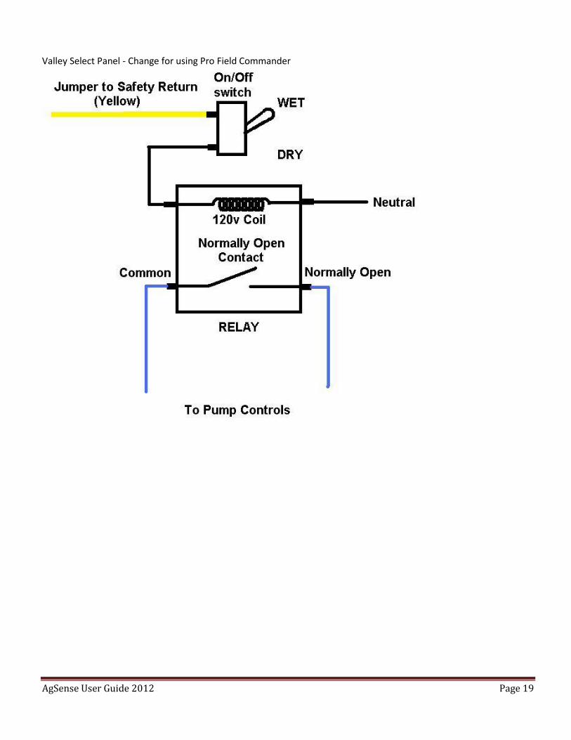
1. At the Panel, run a jumper wire from Safety Return to an on/off switch. (see drawing below)
2. Run another wire from that on/off switch to the coil terminal of a new relay with Normally Open contacts – 120v coil. (see drawing below)
3. Run a jumper wire from the other coil terminal to Neutral.
4. Remove the pump control wires from the panel terminal strip labeled “Pump Control N.O.” and “Pump Control Common” and install them into the Common and Normally Open contacts of the new relay. (see drawing below)
5. Set the digital portion of the panel to “Dry” and leave it that way. – Then use the new toggle switch to control wet/dry.
AgSense User Guide 2012 Page 19
Valley Select Panel - Change for using Pro Field Commander
AgSense User Guide 2012 Page 20
Pierce (Newer systems, example - CP600 pivots) (Read beginning of Section 2 before proceeding): 1. Remove the Pierce yellow (safety) wire from the terminal strip in the end tower box (Span cable wire coming
from the center) , and install our Red/Black wire in its place. 2. Use a wire nut to connect our Red wire to the yellow (safety) wire that was removed from the terminal strip
in step 1. 3. Install our Brown/Black wire into the terminal strip with the other white (neutral) wires. 4. Remove the Pierce purple (percent timer) wire from the terminal strip in the end tower box (Span cable wire
coming from the center) , and install our Blue wire in its place. 5. Use a wire nut to connect our Blue/Black wire to the Pierce purple (percent timer) wire that was removed
from the terminal strip in step 4 6. Remove the Pierce pink (end gun) wire from the terminal strip in the end tower box (Span cable wire coming
from the center) , and install our Brown wire in its place. 7. Use a wire nut to connect our Black wire to the Pierce pink (end gun wire coming from the control panel
(120v all the time)) wire that was removed from the terminal strip in step 6. 8. Install our Orange wire into the tower terminal strip with the Pierce brown wire. (Forward Run) 9. Install our Orange/Black wire into the tower terminal strip with the Pierce orange wire. (Reverse Run)
Pierce (Older systems, example - P.93 pivots) (Read beginning of Section 2 before proceeding):
1. Remove the Pierce brown (safety) wire from the terminal strip in the end tower box (Span cable wire coming from the center), and install our Red/Black wire in its place.
2. Use a wire nut to connect our Red wire to the brown (safety) wire that was removed from the terminal strip in step 1.
3. Install our Brown/Black wire into the terminal strip with the other white (neutral) wires. 4. Remove the Pierce orange (percent timer) wire from the terminal strip in the end tower box (Span cable wire
coming from the center) , and install our Blue wire in its place. 5. Use a wire nut to connect our Blue/Black wire to the Pierce orange (percent timer) wire that was removed
from the terminal strip in step 4 6. Remove the Pierce tan (end gun) wire from the terminal strip in the end tower box (Span cable wire coming
from the center) , and install our Brown wire in its place. 7. Use a wire nut to connect our Black wire to the Pierce tan (end gun wire coming from the control panel (120v
all the time)) wire that was removed from the terminal strip in step 6. 8. Install our Orange wire into the tower terminal strip with the Pierce purple wire. (Forward Run) 9. Install our Orange/Black wire into the tower terminal strip with the Pierce yellow wire. (Reverse Run)
AgSense User Guide 2012 Page 21
Olson: (After 1980) (Read beginning of Section 2 before proceeding) 1. Remove the yellow (safety) wire from the terminal strip in the end tower box (Span Cable Side) and install our
Red/Black wire in its place.
2. Use a wire nut to connect our Red wire to the yellow (safety) wire that was removed from the terminal strip in step 1.
3. Install our Brown/Black wire into the terminal strip with the other white (neutral) wires.
4. Remove the Olson grey (percent timer) wire from the terminal strip in the end tower box (Span Cable Side) and install our Blue wire in its place.
5. Use a wire nut to connect our Blue/Black wire to the Olson grey (percent timer) wire that was removed from the terminal strip in step 4
6. Remove the Olson purple (end gun) wire from the terminal strip in the end tower box (Span Cable Side) and install our Brown wire in its place.
7. Use a wire nut to connect our Black wire to the Olson purple (end gun wire coming from the control panel (120v all the time)) wire that was removed from the terminal strip in step 6.
8. Install our Orange wire into the tower terminal strip with the Olson brown wire. (Forward Run)
9. Install our Orange/Black wire into the tower terminal strip with the Olson white/black wire. (Reverse Run) Lockwood with 16v safety system: - only works on newer systems that do not flip-flop the 120v and Neutral going to the safety transformer. (Read beginning of Section 2 before proceeding)
1. Remove the 120v wire going to the safety transformer and connect our Red/Black wire in its place.
2. Use a wire nut to connect our Red wire to the wire that was removed from the transformer in step 1.
3. Install our Brown/Black wire in with the Neutral wire that goes to the safety transformer.
4. Remove the Lockwood purple (percent timer) wire from the terminal strip in the end tower box and install our Blue wire in its place.
5. Use a wire nut to connect our Blue/Black wire to the Lockwood purple (percent timer) wire that was removed from the terminal strip in step 4.
6. Remove the Lockwood brown (end gun) wire from the terminal strip in the end tower box and install our Brown wire in its place.
7. Use a wire nut to connect our Black wire to the Lockwood brown (end gun wire coming from the control panel (120v all the time)) wire that was removed from the terminal strip in step 6.
8. Install our Orange wire into the tower terminal strip with the Lockwood yellow wire. (Forward Run)
9. Install our Orange/Black wire into the tower terminal strip with the Lockwood orange wire. (Reverse Run) Reinke – See Separate Install Instructions available from AgSense
AgSense User Guide 2012 Page 22
Section 3
Simple Power On/Off Monitor Wiring: This is only to monitor if Power to a device is on or off – there are no controls.
*NOTE* ON ALL UNITS – BLACK WIRE WITH RED STRIPE IS NOT USED 120v AC Device Monitor system: Brown/Black – Neutral Black Wire – 120v AC OR 7-40v DC Device Monitor system: Yellow/Black – Ground Yellow – 7-40v DC
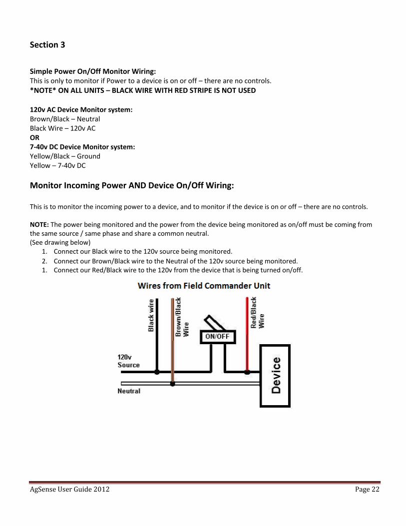
Monitor Incoming Power AND Device On/Off Wiring: This is to monitor the incoming power to a device, and to monitor if the device is on or off – there are no controls. NOTE: The power being monitored and the power from the device being monitored as on/off must be coming from the same source / same phase and share a common neutral. (See drawing below)
1. Connect our Black wire to the 120v source being monitored.
2. Connect our Brown/Black wire to the Neutral of the 120v source being monitored. 1. Connect our Red/Black wire to the 120v from the device that is being turned on/off.
AgSense User Guide 2012 Page 23
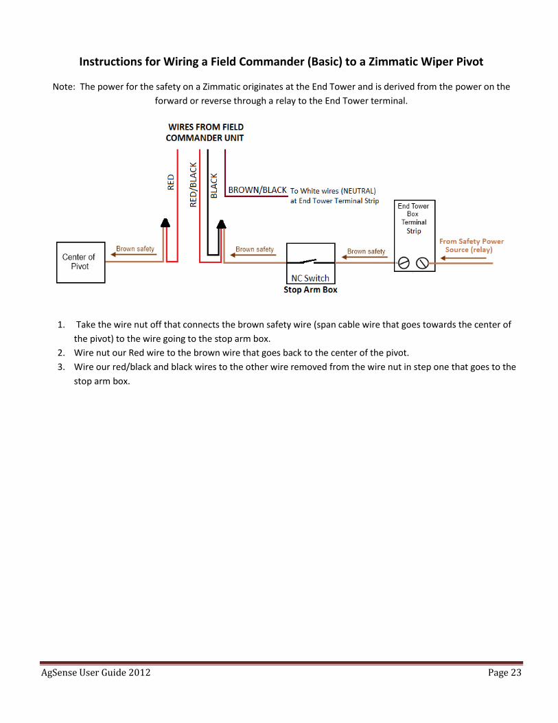
Instructions for Wiring a Field Commander (Basic) to a Zimmatic Wiper Pivot
Note: The power for the safety on a Zimmatic originates at the End Tower and is derived from the power on the
forward or reverse through a relay to the End Tower terminal.
1. Take the wire nut off that connects the brown safety wire (span cable wire that goes towards the center of
the pivot) to the wire going to the stop arm box.
2. Wire nut our Red wire to the brown wire that goes back to the center of the pivot.
3. Wire our red/black and black wires to the other wire removed from the wire nut in step one that goes to the
stop arm box.

AgSense User Guide 2012 Page 24
Field Commander Wiring for Reinke Pivots
Reinke - BASIC/ENHANCED WIRING
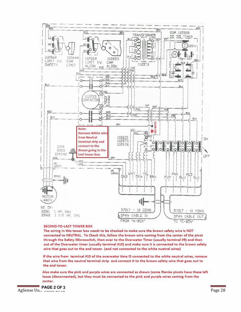
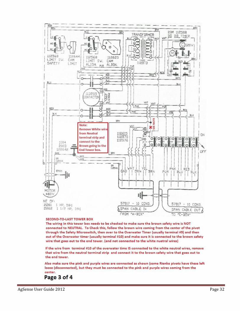
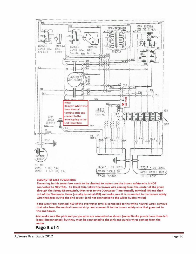
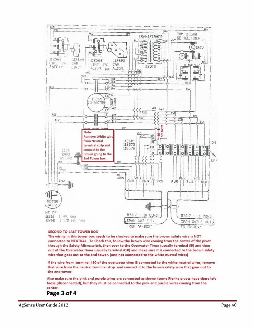
- Note - On some Reinke pivots, the safety circuit begins at the second-to-last tower instead of at the end tower.
(Where the Brown Safety wire connects to the White Neutral wires) On these systems you will need to change the
second-to-last tower and the end tower. In the end tower, make a jumper to connect the white neutral wires to the
brown safety wire. At the second-to-last tower, locate the white wire that connects the overwatering timer contact
(#10 on most) to the neutral wires on the terminal strip. Remove this white wire from the terminal strip, but leave it
connected to the overwatering timer contact. Then, connect that white wire to the brown safety wire that goes out
to the end tower. (This wire most likely is capped or not hooked up to anything in this second-to-last tower box)
You should now have a safety circuit that starts in the end tower box where the brown wire is connected to neutral,
and then travels to the second-to-last tower box on the brown wire, goes to the overwatering timer contact #10,
then exits the overwatering timer on terminal #8, goes to the limit switch, then leaves the limit switch and goes to
the next tower closer to the main panel.
AFTER COMPLETING THIS, YOU MUST TEST THE SAFETY TO BE CERTAIN THE SYSTEM WORKS CORRECTLY. WITH THE
SYSTEM RUNNING, DISCONNECT THE BROWN SAFETY WIRE FROM THE TERMINAL STRIP IN THE END TOWER BOX –
THIS SHOULD SAFETY THE SYSTEM OFF IF THE RE-WIRING WAS DONE CORRECTLY.
ONLY AFTER THIS SAFETY TEST PASSES, THEN PROCEED TO STEP 1 OF THE WIRING BELOW.
Only do Steps 1 – 6 for basic stop feature and tape off unused wires
Add Steps 7 – 8 for speed control
Add Steps 9 – 10 for Endgun control
*NOTE* ON ALL UNITS – BLACK WIRE WITH RED STRIPE IS NOT USED
1. Remove the Reinke brown (safety) wire from the terminal strip in the end tower box (Span cable wire coming from the center) and install our Red/Black AND Brown/Black wires in its place. - See Note at top of page -
2. Use a wire nut to connect our Red wire to the Reinke brown (safety) wire that was removed from the terminal strip in step 1.
3. Install our Black wire into the relay assembly as shown (see Picture 1 below) Relay part number - W78ARCSX-11, and Base part number – 70-459-1
AgSense User Guide 2012 Page 25
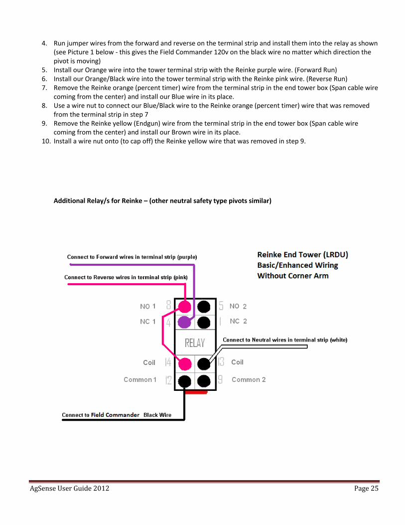
4. Run jumper wires from the forward and reverse on the terminal strip and install them into the relay as shown (see Picture 1 below - this gives the Field Commander 120v on the black wire no matter which direction the pivot is moving)
5. Install our Orange wire into the tower terminal strip with the Reinke purple wire. (Forward Run) 6. Install our Orange/Black wire into the tower terminal strip with the Reinke pink wire. (Reverse Run) 7. Remove the Reinke orange (percent timer) wire from the terminal strip in the end tower box (Span cable wire
coming from the center) and install our Blue wire in its place. 8. Use a wire nut to connect our Blue/Black wire to the Reinke orange (percent timer) wire that was removed
from the terminal strip in step 7 9. Remove the Reinke yellow (Endgun) wire from the terminal strip in the end tower box (Span cable wire
coming from the center) and install our Brown wire in its place. 10. Install a wire nut onto (to cap off) the Reinke yellow wire that was removed in step 9.
Additional Relay/s for Reinke – (other neutral safety type pivots similar)
AgSense User Guide 2012 Page 26
AgSense User Guide 2012 Page 27
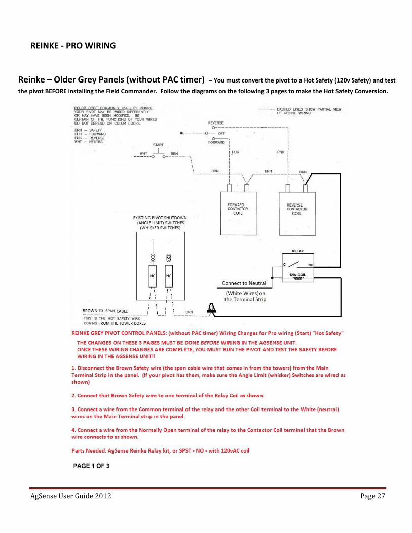
REINKE - PRO WIRING
Reinke – Older Grey Panels (without PAC timer) – You must convert the pivot to a Hot Safety (120v Safety) and test
the pivot BEFORE installing the Field Commander. Follow the diagrams on the following 3 pages to make the Hot Safety Conversion.
AgSense User Guide 2012 Page 28
AgSense User Guide 2012 Page 29
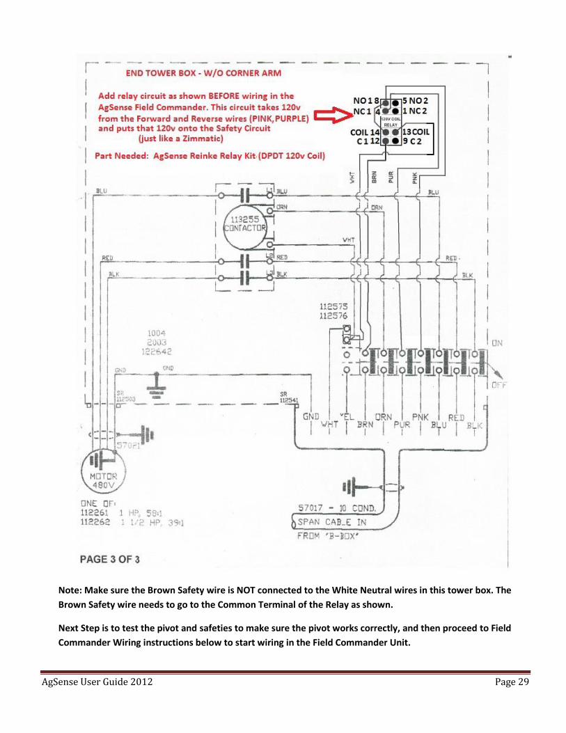
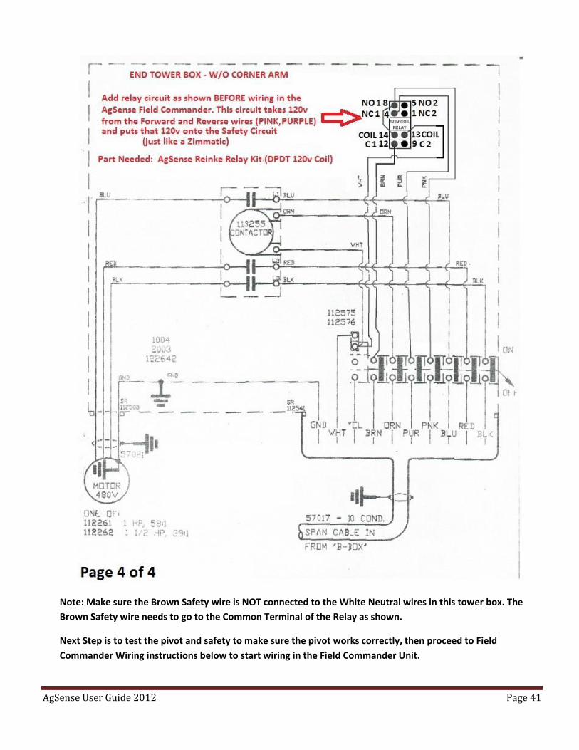
Note: Make sure the Brown Safety wire is NOT connected to the White Neutral wires in this tower box. The
Brown Safety wire needs to go to the Common Terminal of the Relay as shown.
Next Step is to test the pivot and safeties to make sure the pivot works correctly, and then proceed to Field
Commander Wiring instructions below to start wiring in the Field Commander Unit.
AgSense User Guide 2012 Page 30
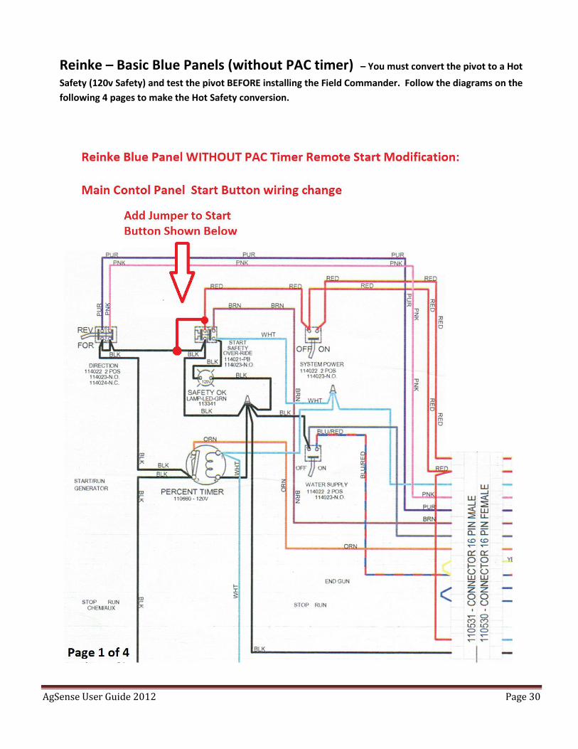
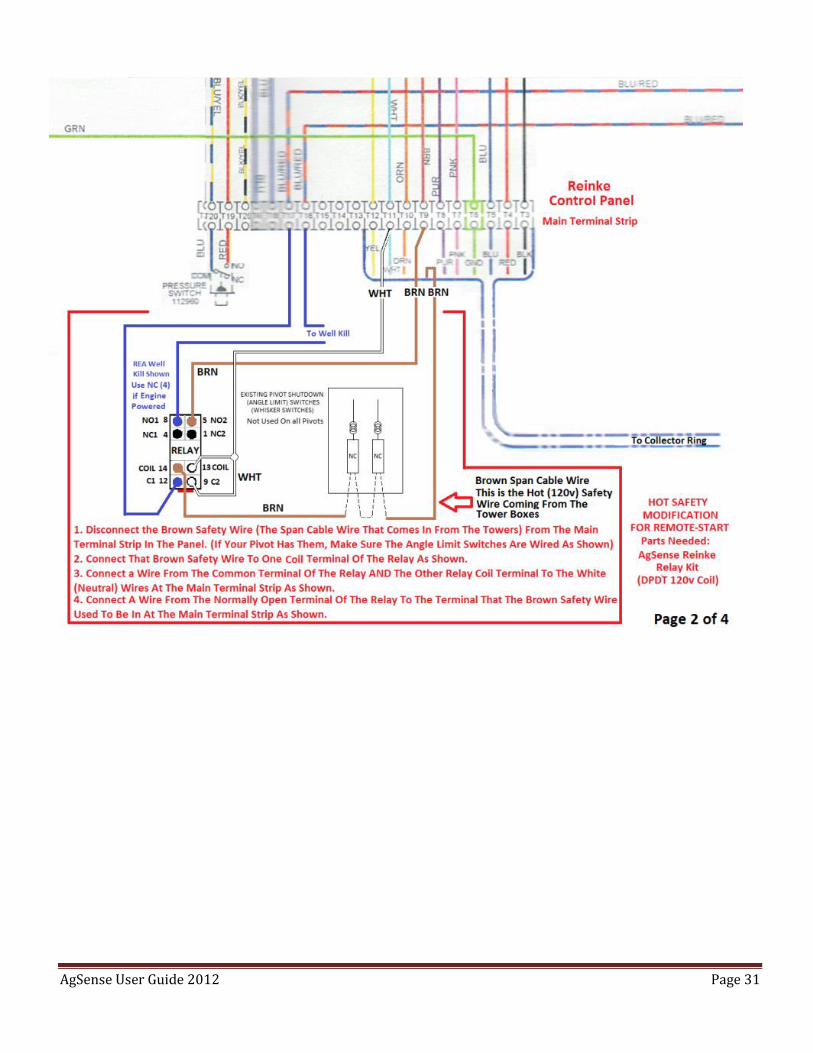
Reinke – Basic Blue Panels (without PAC timer) – You must convert the pivot to a Hot
Safety (120v Safety) and test the pivot BEFORE installing the Field Commander. Follow the diagrams on the
following 4 pages to make the Hot Safety conversion.
AgSense User Guide 2012 Page 31
AgSense User Guide 2012 Page 32
AgSense User Guide 2012 Page 33
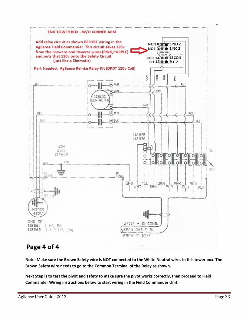
Note: Make sure the Brown Safety wire is NOT connected to the White Neutral wires in this tower box. The
Brown Safety wire needs to go to the Common Terminal of the Relay as shown.
Next Step is to test the pivot and safety to make sure the pivot works correctly, then proceed to Field
Commander Wiring instructions below to start wiring in the Field Commander Unit.
AgSense User Guide 2012 Page 34
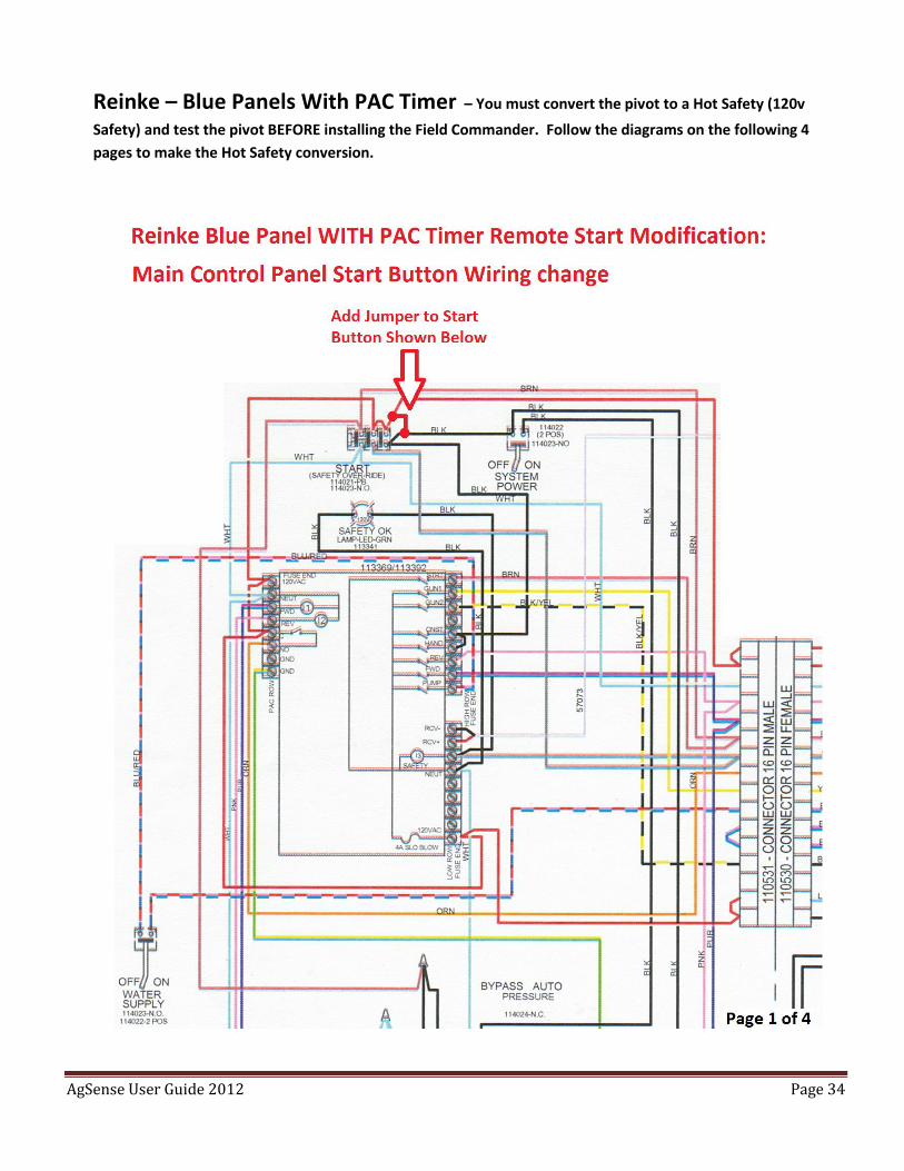
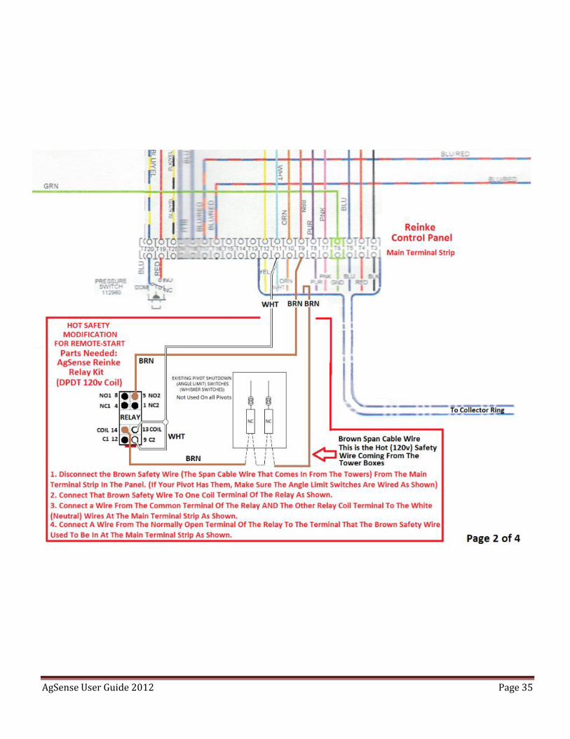
Reinke – Blue Panels With PAC Timer – You must convert the pivot to a Hot Safety (120v
Safety) and test the pivot BEFORE installing the Field Commander. Follow the diagrams on the following 4
pages to make the Hot Safety conversion.
AgSense User Guide 2012 Page 35
AgSense User Guide 2012 Page 36
AgSense User Guide 2012 Page 37
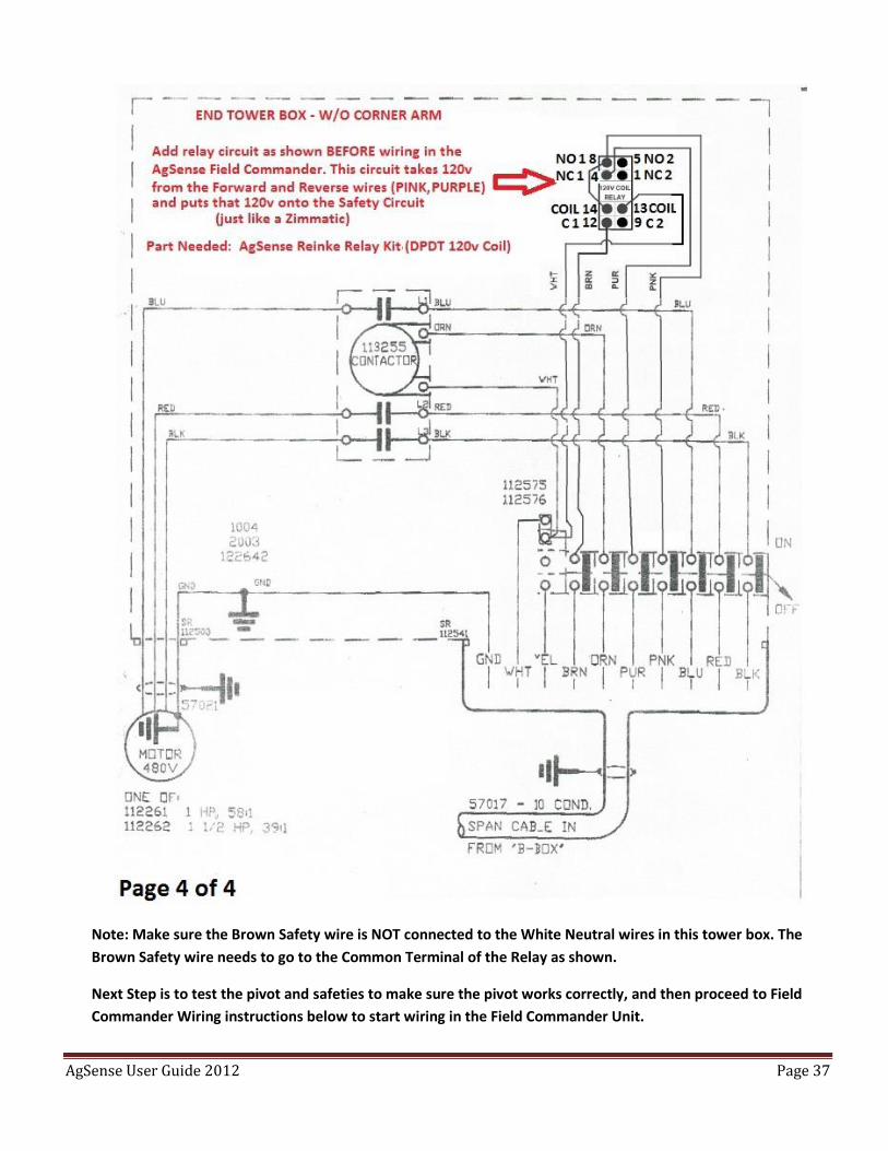
Note: Make sure the Brown Safety wire is NOT connected to the White Neutral wires in this tower box. The
Brown Safety wire needs to go to the Common Terminal of the Relay as shown.
Next Step is to test the pivot and safeties to make sure the pivot works correctly, and then proceed to Field
Commander Wiring instructions below to start wiring in the Field Commander Unit.
AgSense User Guide 2012 Page 38
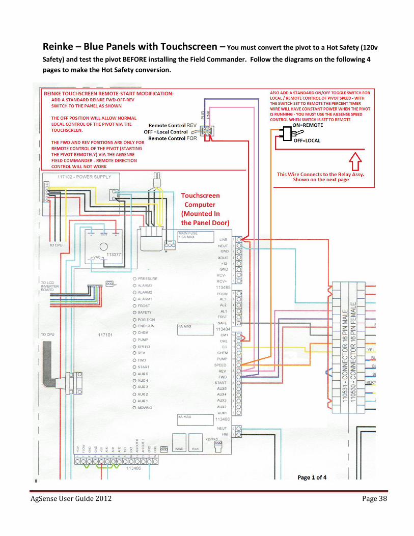
Reinke – Blue Panels with Touchscreen – You must convert the pivot to a Hot Safety (120v
Safety) and test the pivot BEFORE installing the Field Commander. Follow the diagrams on the following 4
pages to make the Hot Safety conversion.
AgSense User Guide 2012 Page 39
AgSense User Guide 2012 Page 40
AgSense User Guide 2012 Page 41
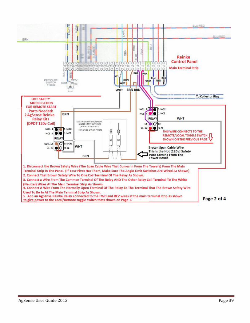
Note: Make sure the Brown Safety wire is NOT connected to the White Neutral wires in this tower box. The
Brown Safety wire needs to go to the Common Terminal of the Relay as shown.
Next Step is to test the pivot and safety to make sure the pivot works correctly, then proceed to Field
Commander Wiring instructions below to start wiring in the Field Commander Unit.
AgSense User Guide 2012 Page 42
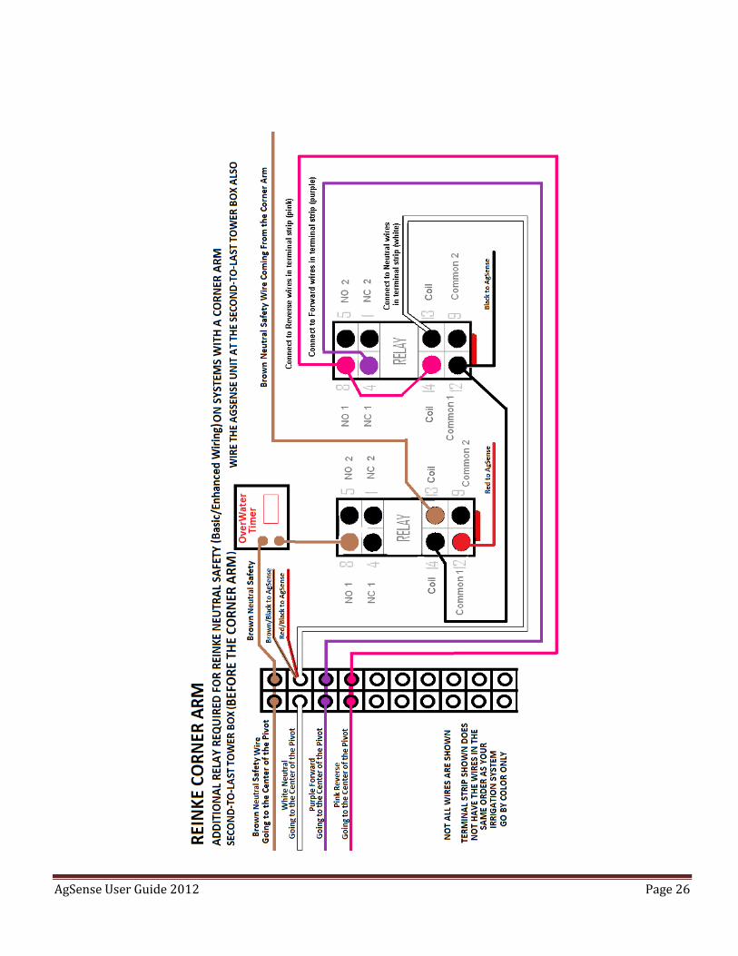
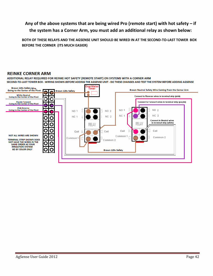
Any of the above systems that are being wired Pro (remote start) with hot safety – if
the system has a Corner Arm, you must add an additional relay as shown below:
BOTH OF THESE RELAYS AND THE AGSENSE UNIT SHOULD BE WIRED IN AT THE SECOND-TO-LAST TOWER BOX
BEFORE THE CORNER (ITS MUCH EASIER)
AgSense User Guide 2012 Page 43
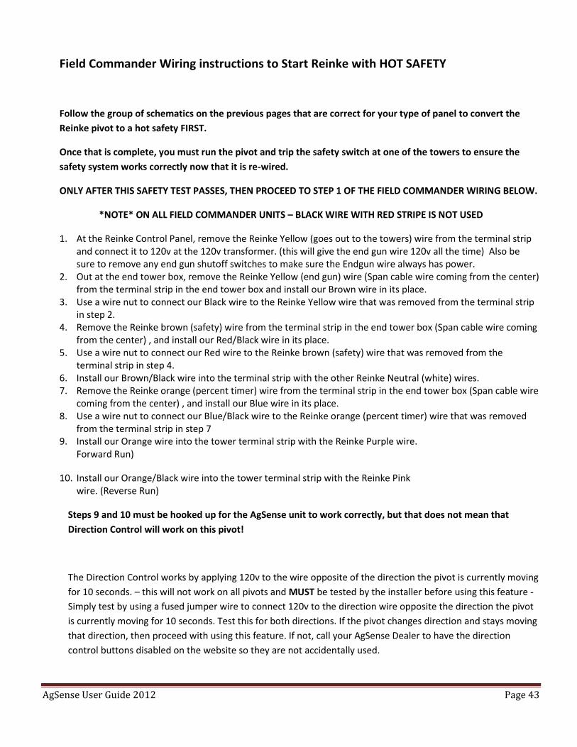
Field Commander Wiring instructions to Start Reinke with HOT SAFETY
Follow the group of schematics on the previous pages that are correct for your type of panel to convert the
Reinke pivot to a hot safety FIRST.
Once that is complete, you must run the pivot and trip the safety switch at one of the towers to ensure the
safety system works correctly now that it is re-wired.
ONLY AFTER THIS SAFETY TEST PASSES, THEN PROCEED TO STEP 1 OF THE FIELD COMMANDER WIRING BELOW.
*NOTE* ON ALL FIELD COMMANDER UNITS – BLACK WIRE WITH RED STRIPE IS NOT USED
1. At the Reinke Control Panel, remove the Reinke Yellow (goes out to the towers) wire from the terminal strip and connect it to 120v at the 120v transformer. (this will give the end gun wire 120v all the time) Also be sure to remove any end gun shutoff switches to make sure the Endgun wire always has power.
2. Out at the end tower box, remove the Reinke Yellow (end gun) wire (Span cable wire coming from the center) from the terminal strip in the end tower box and install our Brown wire in its place.
3. Use a wire nut to connect our Black wire to the Reinke Yellow wire that was removed from the terminal strip in step 2.
4. Remove the Reinke brown (safety) wire from the terminal strip in the end tower box (Span cable wire coming from the center) , and install our Red/Black wire in its place.
5. Use a wire nut to connect our Red wire to the Reinke brown (safety) wire that was removed from the terminal strip in step 4.
6. Install our Brown/Black wire into the terminal strip with the other Reinke Neutral (white) wires. 7. Remove the Reinke orange (percent timer) wire from the terminal strip in the end tower box (Span cable wire
coming from the center) , and install our Blue wire in its place. 8. Use a wire nut to connect our Blue/Black wire to the Reinke orange (percent timer) wire that was removed
from the terminal strip in step 7 9. Install our Orange wire into the tower terminal strip with the Reinke Purple wire.
Forward Run)
10. Install our Orange/Black wire into the tower terminal strip with the Reinke Pink wire. (Reverse Run)
Steps 9 and 10 must be hooked up for the AgSense unit to work correctly, but that does not mean that
Direction Control will work on this pivot!
The Direction Control works by applying 120v to the wire opposite of the direction the pivot is currently moving
for 10 seconds. – this will not work on all pivots and MUST be tested by the installer before using this feature -
Simply test by using a fused jumper wire to connect 120v to the direction wire opposite the direction the pivot
is currently moving for 10 seconds. Test this for both directions. If the pivot changes direction and stays moving
that direction, then proceed with using this feature. If not, call your AgSense Dealer to have the direction
control buttons disabled on the website so they are not accidentally used.
AgSense User Guide 2012 Page 44
AgSense User Guide 2012 Page 45
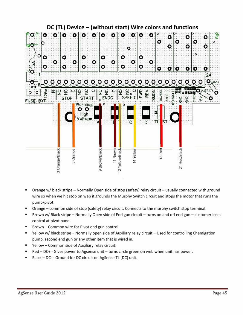
DC (TL) Device – (without start) Wire colors and functions
Orange w/ black stripe – Normally Open side of stop (safety) relay circuit – usually connected with ground
wire so when we hit stop on web it grounds the Murphy Switch circuit and stops the motor that runs the
pump/pivot.
Orange – common side of stop (safety) relay circuit. Connects to the murphy switch stop terminal.
Brown w/ Black stripe – Normally Open side of End gun circuit – turns on and off end gun – customer loses
control at pivot panel.
Brown – Common wire for Pivot end gun control.
Yellow w/ black stripe – Normally open side of Auxiliary relay circuit – Used for controlling Chemigation
pump, second end gun or any other item that is wired in.
Yellow – Common side of Auxiliary relay circuit.
Red – DC+ - Gives power to Agsense unit – turns circle green on web when unit has power.
Black – DC- - Ground for DC circuit on AgSense TL (DC) unit.
AgSense User Guide 2012 Page 46
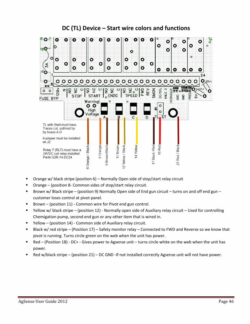
DC (TL) Device – Start wire colors and functions
Orange w/ black stripe (position 6) – Normally Open side of stop/start relay circuit
Orange – (position 8- Common sides of stop/start relay circuit.
Brown w/ Black stripe – (position 9) Normally Open side of End gun circuit – turns on and off end gun –
customer loses control at pivot panel.
Brown – (position 11) - Common wire for Pivot end gun control.
Yellow w/ black stripe – (position 12) - Normally open side of Auxiliary relay circuit – Used for controlling
Chemigation pump, second end gun or any other item that is wired in.
Yellow – (position 14) - Common side of Auxiliary relay circuit.
Black w/ red stripe – (Position 17) – Safety monitor relay – Connected to FWD and Reverse so we know that
pivot is running. Turns circle green on the web when the unit has power.
Red – (Position 18) - DC+ - Gives power to Agsense unit – turns circle white on the web when the unit has
power.
Red w/black stripe – (position 21) – DC GND -If not installed correctly Agsense unit will not have power.
AgSense User Guide 2012 Page 47
Separate T-L Wiring Guides for 24VDC Monitor, Start and Precision
Link in separate document
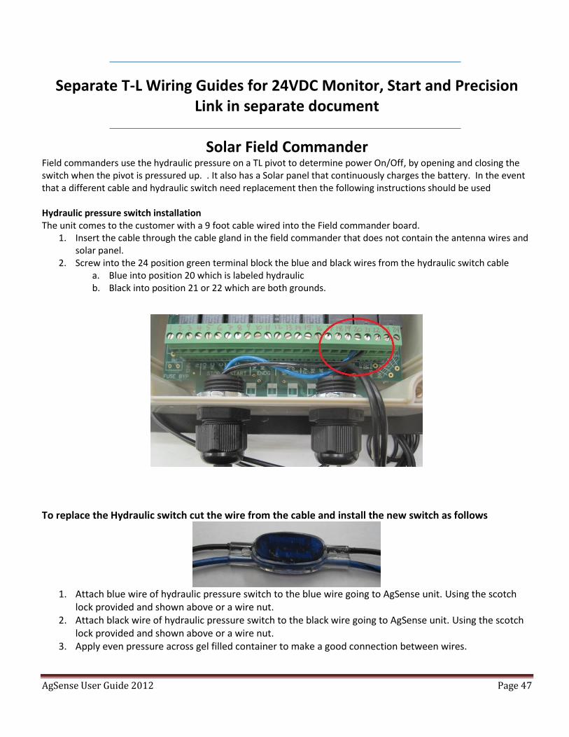
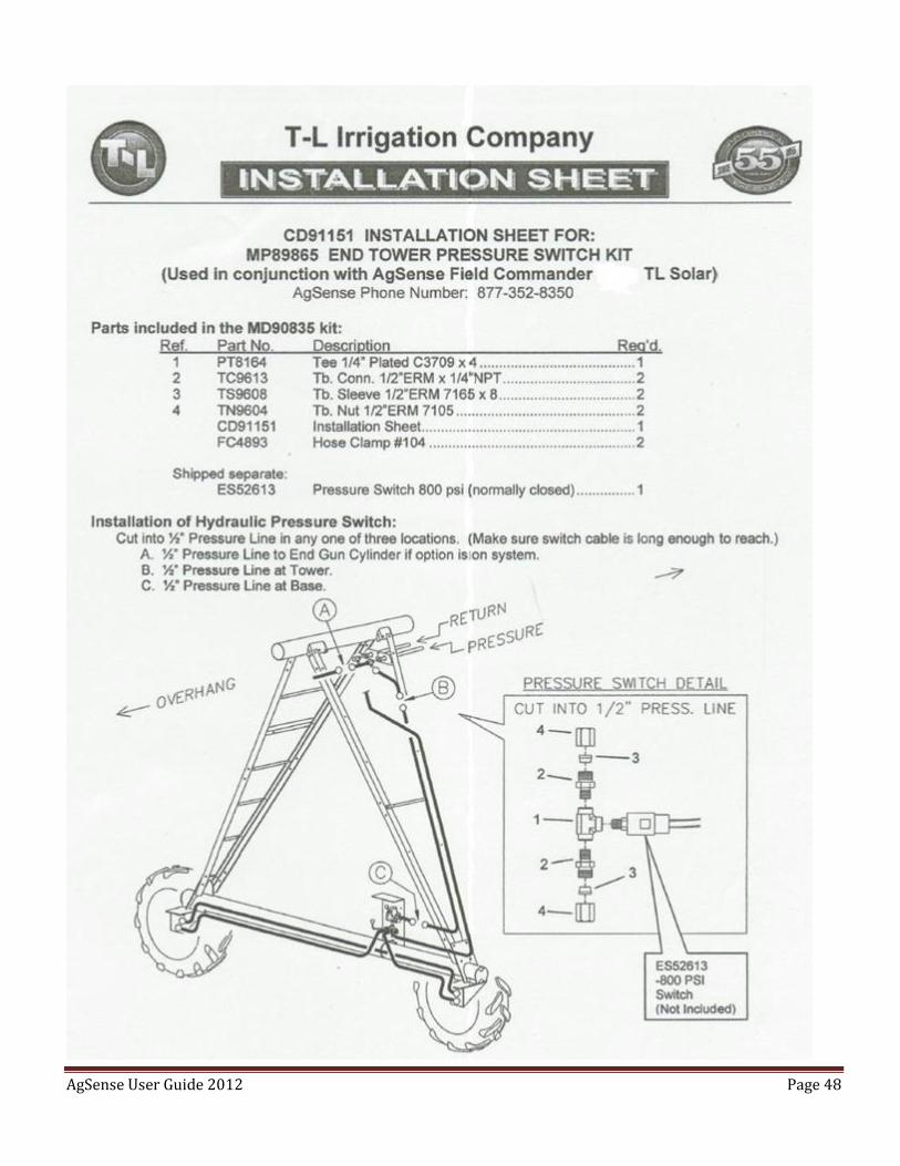
Solar Field Commander Field commanders use the hydraulic pressure on a TL pivot to determine power On/Off, by opening and closing the switch when the pivot is pressured up. . It also has a Solar panel that continuously charges the battery. In the event that a different cable and hydraulic switch need replacement then the following instructions should be used Hydraulic pressure switch installation The unit comes to the customer with a 9 foot cable wired into the Field commander board.
1. Insert the cable through the cable gland in the field commander that does not contain the antenna wires and solar panel.
2. Screw into the 24 position green terminal block the blue and black wires from the hydraulic switch cable a. Blue into position 20 which is labeled hydraulic b. Black into position 21 or 22 which are both grounds.
To replace the Hydraulic switch cut the wire from the cable and install the new switch as follows
1. Attach blue wire of hydraulic pressure switch to the blue wire going to AgSense unit. Using the scotch
lock provided and shown above or a wire nut. 2. Attach black wire of hydraulic pressure switch to the black wire going to AgSense unit. Using the scotch
lock provided and shown above or a wire nut. 3. Apply even pressure across gel filled container to make a good connection between wires.
AgSense User Guide 2012 Page 48
AgSense User Guide 2012 Page 49
Field Commander Lite wiring manual Section 1 – Irrigation System Wiring – Stop Only: Warning: Only 4 wires are used on these installations – all unused wires must be capped or taped off individually to avoid damage to unit. Safety circuit must be tested by the installer before AND after installation is finished.
*NOTE* ON ALL UNITS – BLACK WIRE WITH RED STRIPE IS NOT USED Zimmatic:
1. Remove the Zimmatic brown (safety) wire from the terminal strip in the end tower box (Span Cable Side) and install our Black wire AND Red/Black wire in its place.
2. Use a wire nut to connect our Red wire to the Zimmatic brown (safety) wire that was removed from the terminal strip in step 1.
3. Install our Brown/Black wire into the terminal strip with the other white (neutral) wires.
Valley: 1. Remove the Valley yellow (safety) wire from the terminal strip in the end tower box (Span Cable Side) and
install our Black wire AND Red/Black wire in its place.
2. Use a wire nut to connect our Red wire to the Valley yellow (safety) wire that was removed from the terminal strip in step 1.
3. Install our Brown/Black wire into the terminal strip with the other white (neutral) wires.
Olson: (After 1980) 1. Remove the yellow (safety) wire from the terminal strip in the end tower box (Span Cable Side) and install our
Black wire AND Red/Black wire in its place.
2. Use a wire nut to connect our Red wire to the yellow (safety) wire that was removed from the terminal strip in step 1.
3. Install our Brown/Black wire into the terminal strip with the other white (neutral) wires.
Lockwood with 16v safety system: 1. Remove the 120v wire going to the safety transformer and connect our Black wire AND Red/Black wire in its
place.
2. Use a wire nut to connect our Red wire to the wire that was removed from the transformer in step 1.
3. Install our Brown/Black wire in with the other neutral (white) wires. -see note-
-Note- on older Lockwood systems, the power to the safety transformer is flip-flopped depending on which direction the system is moving. On these, change step 3 to this: Install our Brown/Black wire into the other 120v terminal on the safety transformer. (With the wire that was not
disturbed in step 1 or 2)
AgSense User Guide 2012 Page 50
Reinke/Neutral Safety Wiring for FC Lite
Reinke – And Similar Neutral Safety Systems
- Note - On some Reinke pivots, the safety circuit begins at the second-to-last tower instead of at the end tower.
(Where the Brown Safety wire connects to the White Neutral wires) On these systems you will need to change the
second-to-last tower and the end tower. In the end tower, make a jumper to connect the white neutral wires to the
brown safety wire. At the second-to-last tower, locate the white wire that connects the overwatering timer contact
(#10 on most) to the neutral wires on the terminal strip. Remove this white wire from the terminal strip, but leave it
connected to the overwatering timer contact. Then, connect that white wire to the brown safety wire that goes out
to the end tower. (This wire most likely is capped or not hooked up to anything in this second-to-last tower box)
You should now have a safety circuit that starts in the end tower box where the brown wire is connected to neutral,
and then travels to the second-to-last tower box on the brown wire, goes to the overwatering timer contact #10,
then exits the overwatering timer on terminal #8, goes to the limit switch, then leaves the limit switch and goes to
the next tower closer to the main panel.
AFTER COMPLETING THIS, YOU MUST TEST THE SAFETY TO BE CERTAIN THE SYSTEM WORKS CORRECTLY. WITH THE
SYSTEM RUNNING, DISCONNECT THE BROWN SAFETY WIRE FROM THE TERMINAL STRIP IN THE END TOWER BOX –
THIS SHOULD SAFETY THE SYSTEM OFF IF THE RE-WIRING WAS DONE CORRECTLY.
ONLY AFTER THIS SAFETY TEST PASSES, THEN PROCEED TO STEP 1 OF THE Field Commander WIRING BELOW.
*NOTE* ON ALL UNITS – BLACK WIRE WITH RED STRIPE IS NOT USED
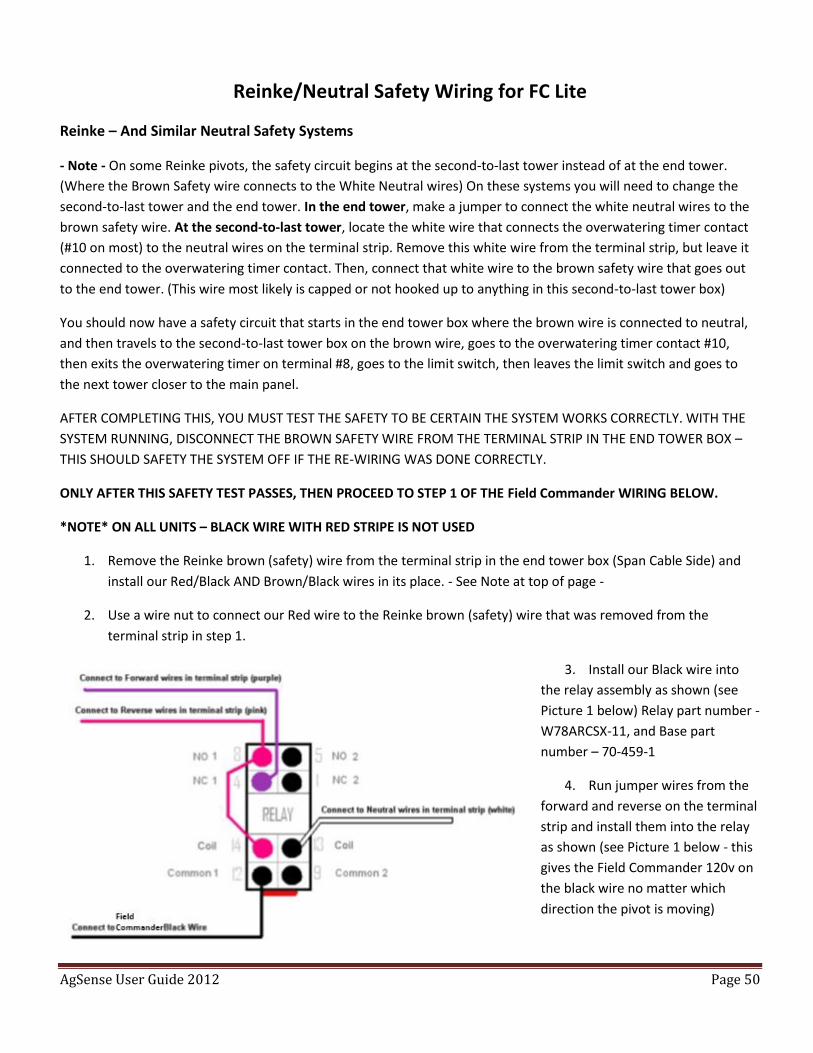
1. Remove the Reinke brown (safety) wire from the terminal strip in the end tower box (Span Cable Side) and
install our Red/Black AND Brown/Black wires in its place. - See Note at top of page -
2. Use a wire nut to connect our Red wire to the Reinke brown (safety) wire that was removed from the
terminal strip in step 1.
3. Install our Black wire into
the relay assembly as shown (see
Picture 1 below) Relay part number -
W78ARCSX-11, and Base part
number – 70-459-1
4. Run jumper wires from the
forward and reverse on the terminal
strip and install them into the relay
as shown (see Picture 1 below - this
gives the Field Commander 120v on
the black wire no matter which
direction the pivot is moving)
AgSense User Guide 2012 Page 51
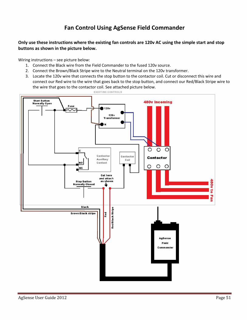
Fan Control Using AgSense Field Commander
Only use these instructions where the existing fan controls are 120v AC using the simple start and stop buttons as shown in the picture below. Wiring instructions – see picture below:
1. Connect the Black wire from the Field Commander to the fused 120v source. 2. Connect the Brown/Black Stripe wire to the Neutral terminal on the 120v transformer. 3. Locate the 120v wire that connects the stop button to the contactor coil. Cut or disconnect this wire and
connect our Red wire to the wire that goes back to the stop button, and connect our Red/Black Stripe wire to the wire that goes to the contactor coil. See attached picture below.
AgSense User Guide 2012 Page 52
Post Installation requirements for Field Commander
Once a unit has been installed on a pivot is suggest that the following procedures be completed before
leaving the field.
1. Turn pivot on and check wagnet.net to see if Field Commander has installed.
2. Check each function that is expected to work when watering (Stop, Start, Direction change etc.)
3. Check the pivot panel switches to make sure they are still functional
4. On Wagnet.net setup the pivot on the Main Cfg, center of pivot and text messaging.
NOTES:
AgSense User Guide 2012 Page 53
Field Commander accessory installations
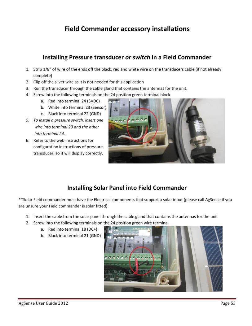
Installing Pressure transducer or switch in a Field Commander
1. Strip 1/8” of wire of the ends off the black, red and white wire on the transducers cable (if not already
complete)
2. Clip off the silver wire as it is not needed for this application
3. Run the transducer through the cable gland that contains the antennas for the unit.
4. Screw into the following terminals on the 24 position green terminal block.
a. Red into terminal 24 (5VDC)
b. White into terminal 23 (Sensor)
c. Black into terminal 22 (GND)
5. To install a pressure switch, insert one
wire into terminal 23 and the other
into terminal 24.
6. Refer to the web instructions for
configuration instructions of pressure
transducer, so it will display correctly.
Installing Solar Panel into Field Commander
**Solar Field commander must have the Electrical components that support a solar input (please call AgSense if you
are unsure your Field commander is solar fitted)
1. Insert the cable from the solar panel through the cable gland that contains the antennas for the unit
2. Screw into the following terminals on the 24 position green wire terminal
a. Red into terminal 18 (DC+)
b. Black into terminal 21 (GND)
AgSense User Guide 2012 Page 54
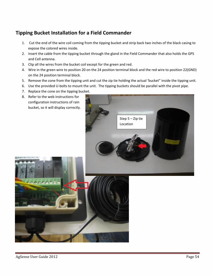
Tipping Bucket Installation for a Field Commander
1. Cut the end of the wire coil coming from the tipping bucket and strip back two inches of the black casing to
expose the colored wires inside.
2. Insert the cable from the tipping bucket through the gland in the Field Commander that also holds the GPS
and Cell antenna.
3. Clip all the wires from the bucket coil except for the green and red.
4. Wire in the green wire to position 20 on the 24 position terminal block and the red wire to position 22(GND)
on the 24 position terminal block.
5. Remove the cone from the tipping unit and cut the zip tie holding the actual ‘bucket” inside the tipping unit.
6. Use the provided U-bolts to mount the unit. The tipping buckets should be parallel with the pivot pipe.
7. Replace the cone on the tipping bucket.
8. Refer to the web instructions for
configuration instructions of rain
bucket, so it will display correctly.
Step 5 – Zip tie
Location
AgSense User Guide 2012 Page 55
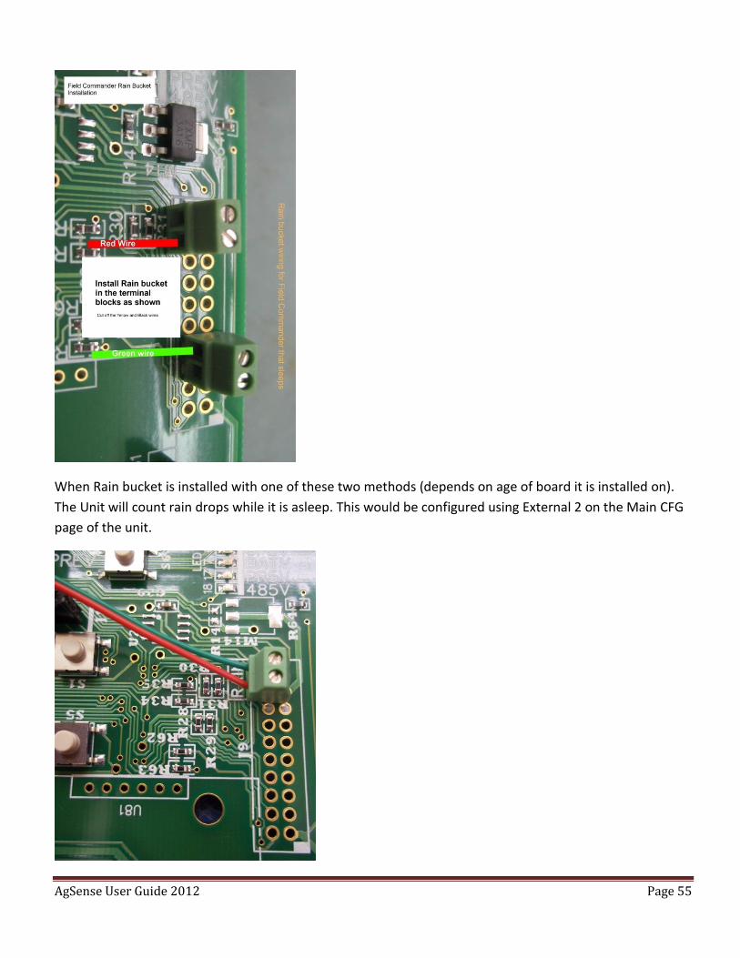
When Rain bucket is installed with one of these two methods (depends on age of board it is installed on).
The Unit will count rain drops while it is asleep. This would be configured using External 2 on the Main CFG
page of the unit.
AgSense User Guide 2012 Page 56
Crop Link Introduction
A Crop Link when used either independently or in conjunction with a Field Commander gives you the ability
to monitor and control multiple devices from a single web page.
The Crop Link includes a modem (radio) that sends the data it gathers to the AgSense servers, where it is
then merged with the Field Commander data for viewing of all inputs on a single, easy to read page.
Wagnet’s network technology allows you to have an unlimited number of Crop Link devices reporting to a
single Web page.
Features that the Crop Link can control or monitor include water pumps, chemigation pumps, weather
components, soil moisture, flow meters and relay states.
AgSense User Guide 2012 Page 57
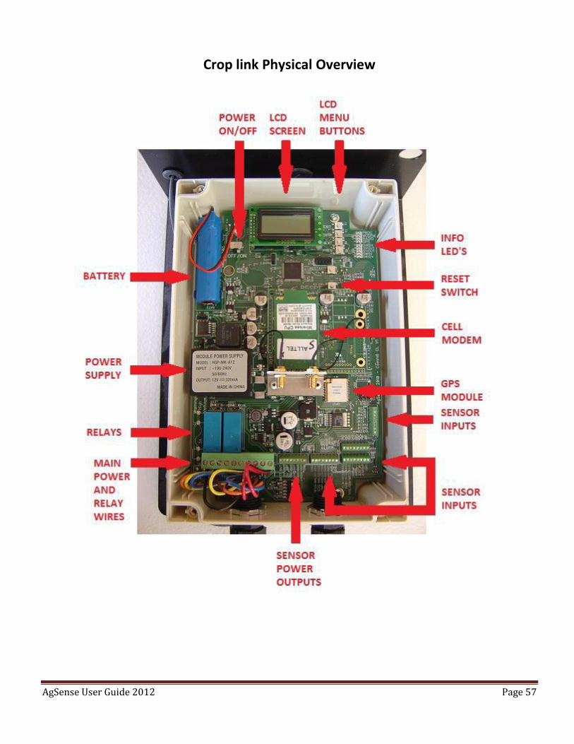
Crop link Physical Overview
AgSense User Guide 2012 Page 58
Crop Link Types – Functions and Capabilities
Control Capabilities – The Crop Link (120VAC and 24VDC) can:
1. Turn on and off 2 separate relays attached to pumps or compatible accessories.
Monitor Capabilities – The Crop Link (120VAC and 24VDC) can monitor:
1. Weather components such as:
a. Rain buckets
b. Temperature sensors
c. Humidity Sensors
d. Anemometers that measure wind direction and wind speed.
2. Flow Meters of the following types:
a. Netafim flow meter
b. GF Signet “Open Collector” flow meter
c. GF Signet 8550 flow transmitter
d. McCrometer flow meter
e. Seametrics AG2000 flow meter.
3. Temperatures within a grain bin by adding an external sensor board. The sensor board (GT63), which is
wired directly into the Crop Link collects the temperature measurements. The Crop Link in turn reads the
information and conveys it to the web.
4. Multiple water pressure sensors.
5. Aquacheck Soil Moisture Probe. *Note: A Crop Link with Solar Panel is used to monitor the Aquacheck probe
thus eliminating the need for 120VAC or 24VDC.
AgSense User Guide 2012 Page 59
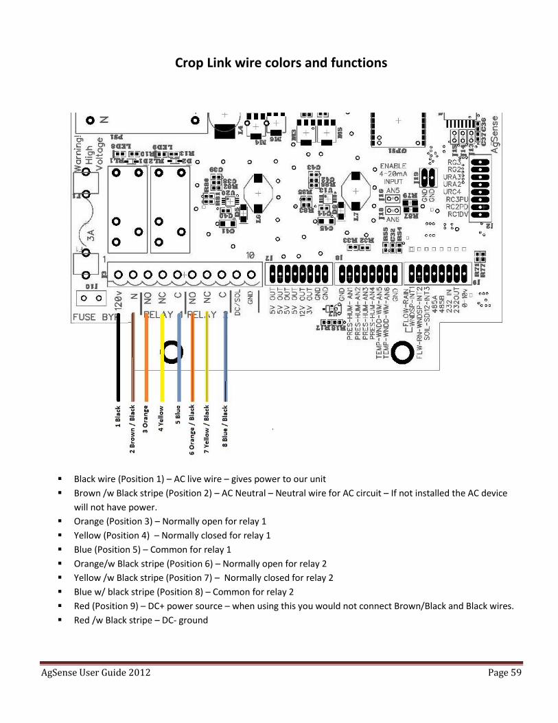
Crop Link wire colors and functions
Black wire (Position 1) – AC live wire – gives power to our unit
Brown /w Black stripe (Position 2) – AC Neutral – Neutral wire for AC circuit – If not installed the AC device
will not have power.
Orange (Position 3) – Normally open for relay 1
Yellow (Position 4) – Normally closed for relay 1
Blue (Position 5) – Common for relay 1
Orange/w Black stripe (Position 6) – Normally open for relay 2
Yellow /w Black stripe (Position 7) – Normally closed for relay 2
Blue w/ black stripe (Position 8) – Common for relay 2
Red (Position 9) – DC+ power source – when using this you would not connect Brown/Black and Black wires.
Red /w Black stripe – DC- ground
AgSense User Guide 2012 Page 60
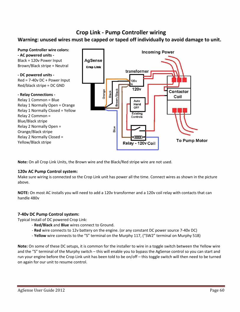
Crop Link - Pump Controller wiring Warning: unused wires must be capped or taped off individually to avoid damage to unit.
Pump Controller wire colors: - AC powered units - Black = 120v Power Input Brown/Black stripe = Neutral
- DC powered units - Red = 7-40v DC + Power Input Red/black stripe = DC GND
- Relay Connections - Relay 1 Common = Blue Relay 1 Normally Open = Orange Relay 1 Normally Closed = Yellow Relay 2 Common = Blue/Black stripe Relay 2 Normally Open = Orange/Black stripe Relay 2 Normally Closed = Yellow/Black stripe
Note: On all Crop Link Units, the Brown wire and the Black/Red stripe wire are not used.
120v AC Pump Control system: Make sure wiring is connected so the Crop Link unit has power all the time. Connect wires as shown in the picture above. NOTE: On most AC installs you will need to add a 120v transformer and a 120v coil relay with contacts that can handle 480v
7-40v DC Pump Control system: Typical Install of DC powered Crop Link:
- Red/Black and Blue wires connect to Ground. - Red wire connects to 12v battery on the engine. (or any constant DC power source 7-40v DC) - Yellow wire connects to the “S” terminal on the Murphy 117, (“SW2” terminal on Murphy 518)
Note: On some of these DC setups, it is common for the installer to wire in a toggle switch between the Yellow wire and the “S” terminal of the Murphy switch – this will enable you to bypass the AgSense control so you can start and run your engine before the Crop Link unit has been told to be on/off – this toggle switch will then need to be turned on again for our unit to resume control.
AgSense User Guide 2012 Page 61
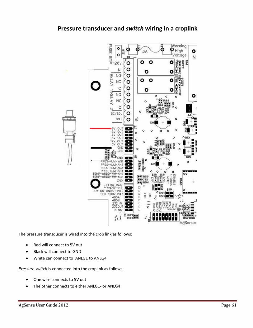
Pressure transducer and switch wiring in a croplink
The pressure transducer is wired into the crop link as follows:
Red will connect to 5V out
Black will connect to GND
White can connect to ANLG1 to ANLG4
Pressure switch is connected into the croplink as follows:
One wire connects to 5V out
The other connects to either ANLG1- or ANLG4
AgSense User Guide 2012 Page 62
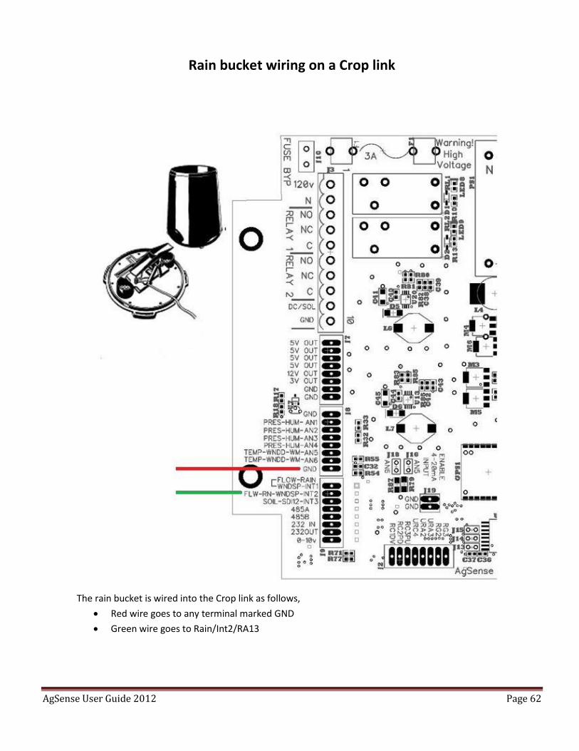
Rain bucket wiring on a Crop link
The rain bucket is wired into the Crop link as follows,
Red wire goes to any terminal marked GND
Green wire goes to Rain/Int2/RA13
AgSense User Guide 2012 Page 63
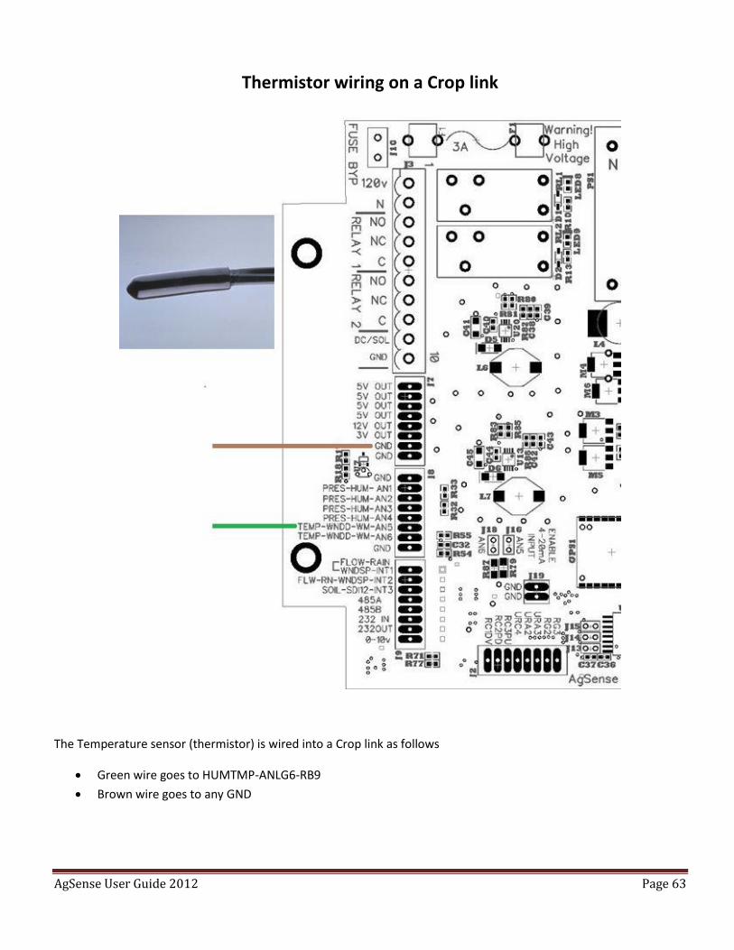
Thermistor wiring on a Crop link
The Temperature sensor (thermistor) is wired into a Crop link as follows
Green wire goes to HUMTMP-ANLG6-RB9
Brown wire goes to any GND
AgSense User Guide 2012 Page 64
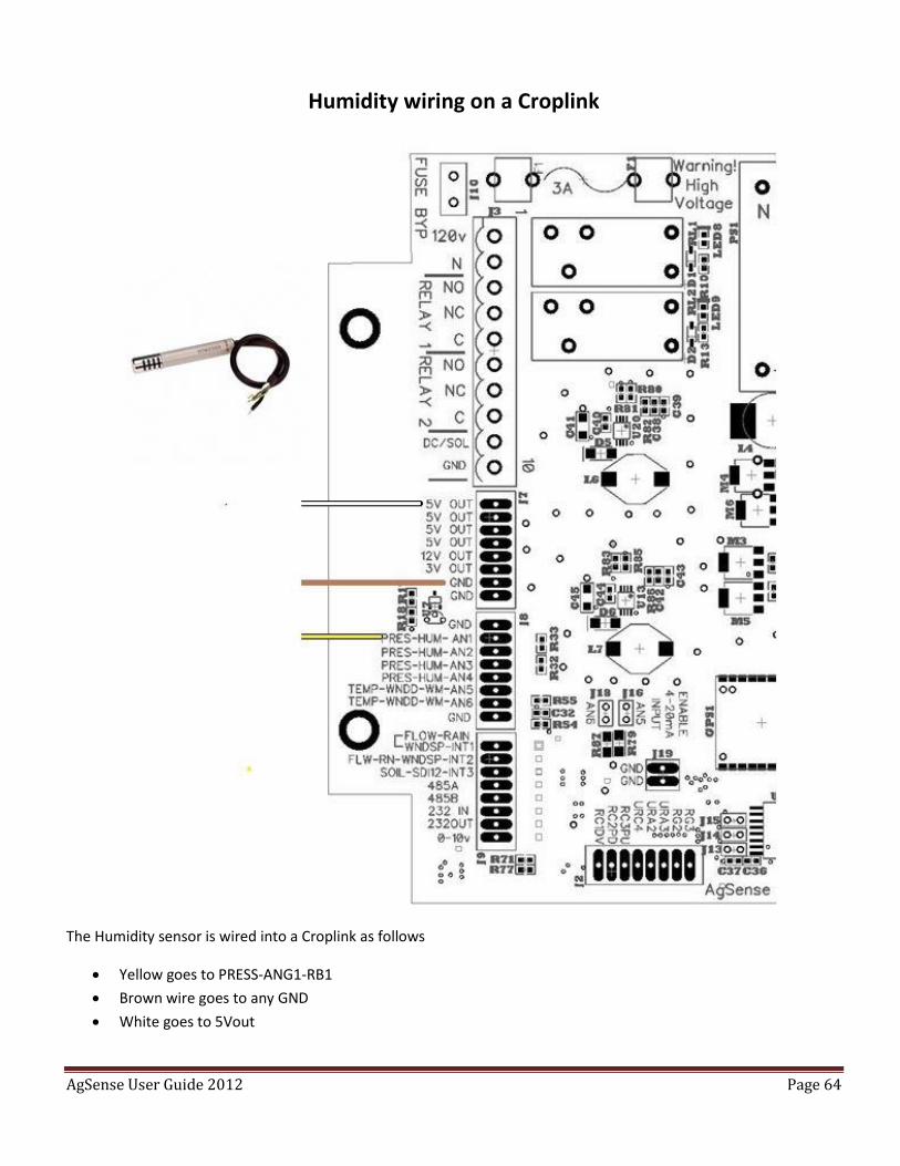
Humidity wiring on a Croplink
The Humidity sensor is wired into a Croplink as follows
Yellow goes to PRESS-ANG1-RB1
Brown wire goes to any GND
White goes to 5Vout
AgSense User Guide 2012 Page 65
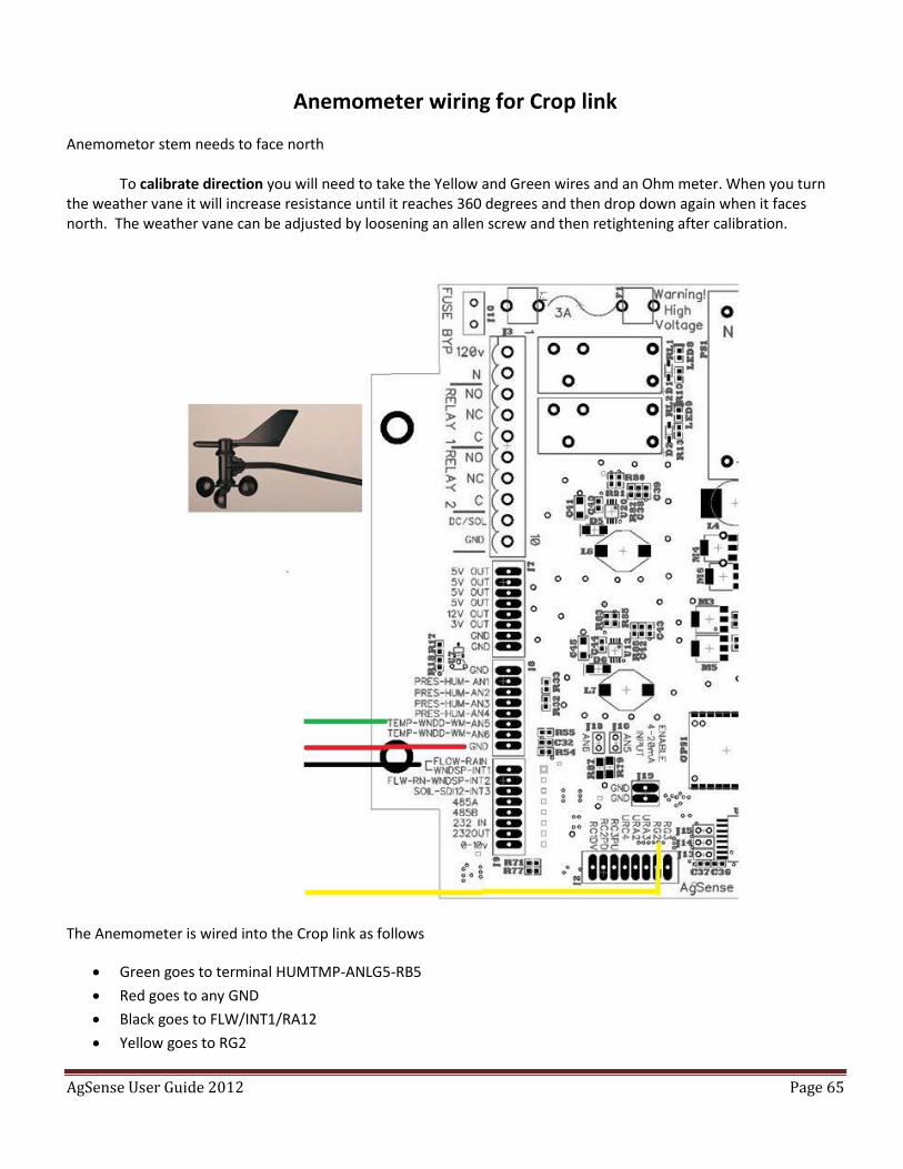
Anemometer wiring for Crop link
Anemometor stem needs to face north
To calibrate direction you will need to take the Yellow and Green wires and an Ohm meter. When you turn the weather vane it will increase resistance until it reaches 360 degrees and then drop down again when it faces north. The weather vane can be adjusted by loosening an allen screw and then retightening after calibration.
The Anemometer is wired into the Crop link as follows
Green goes to terminal HUMTMP-ANLG5-RB5
Red goes to any GND
Black goes to FLW/INT1/RA12
Yellow goes to RG2
AgSense User Guide 2012 Page 66
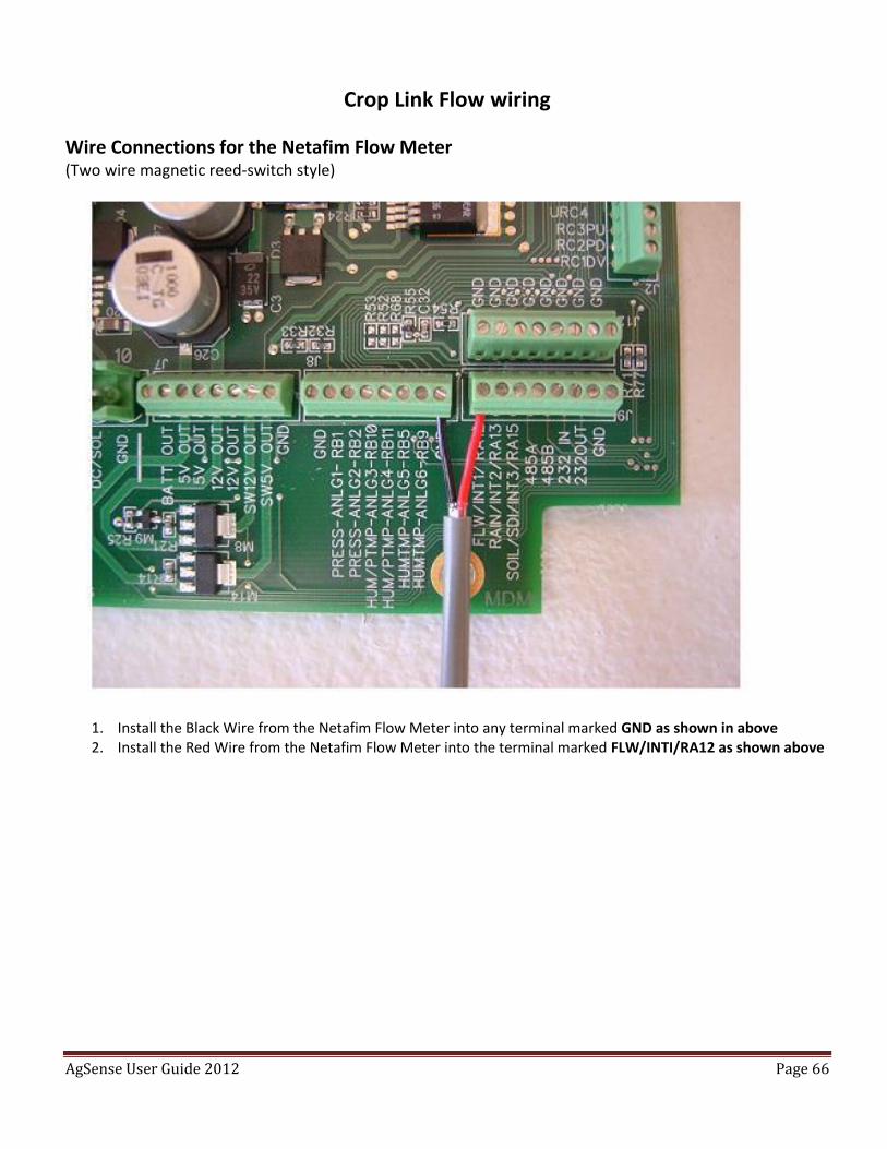
Crop Link Flow wiring
Wire Connections for the Netafim Flow Meter (Two wire magnetic reed-switch style)
1. Install the Black Wire from the Netafim Flow Meter into any terminal marked GND as shown in above 2. Install the Red Wire from the Netafim Flow Meter into the terminal marked FLW/INTI/RA12 as shown above
AgSense User Guide 2012 Page 67
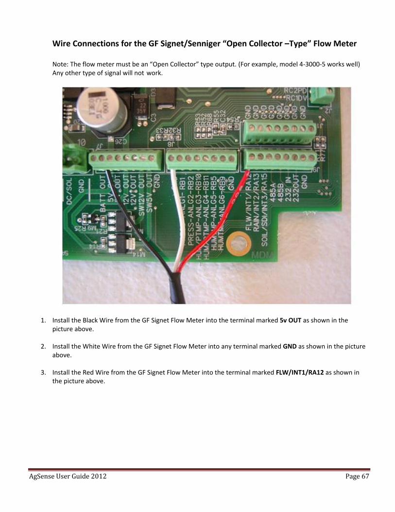
Wire Connections for the GF Signet/Senniger “Open Collector –Type” Flow Meter Note: The flow meter must be an “Open Collector” type output. (For example, model 4-3000-5 works well) Any other type of signal will not work.
1. Install the Black Wire from the GF Signet Flow Meter into the terminal marked 5v OUT as shown in the
picture above.
2. Install the White Wire from the GF Signet Flow Meter into any terminal marked GND as shown in the picture above.
3. Install the Red Wire from the GF Signet Flow Meter into the terminal marked FLW/INT1/RA12 as shown in
the picture above.
AgSense User Guide 2012 Page 68
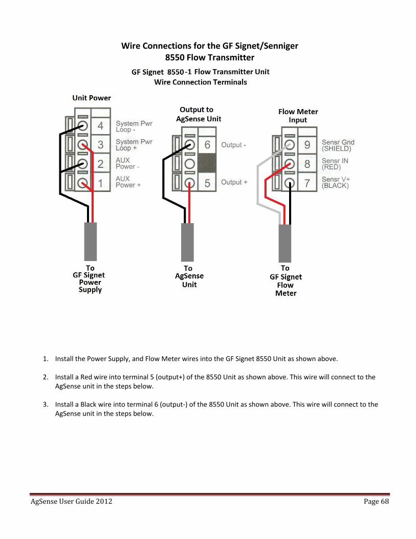
Wire Connections for the GF Signet/Senniger 8550 Flow Transmitter
1. Install the Power Supply, and Flow Meter wires into the GF Signet 8550 Unit as shown above.
2. Install a Red wire into terminal 5 (output+) of the 8550 Unit as shown above. This wire will connect to the
AgSense unit in the steps below.
3. Install a Black wire into terminal 6 (output-) of the 8550 Unit as shown above. This wire will connect to the AgSense unit in the steps below.
AgSense User Guide 2012 Page 69
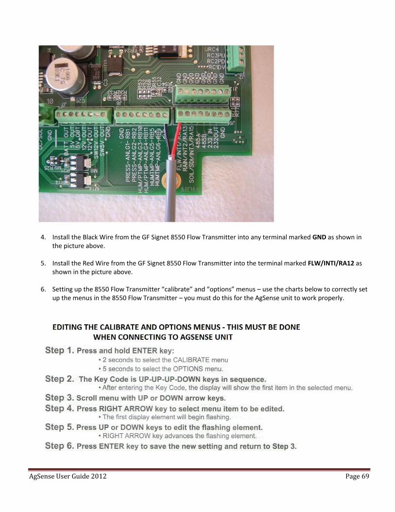
4. Install the Black Wire from the GF Signet 8550 Flow Transmitter into any terminal marked GND as shown in
the picture above.
5. Install the Red Wire from the GF Signet 8550 Flow Transmitter into the terminal marked FLW/INTI/RA12 as shown in the picture above.
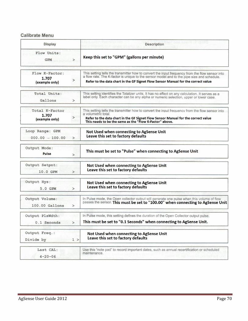
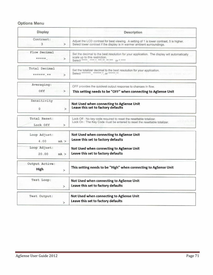
6. Setting up the 8550 Flow Transmitter “calibrate” and “options” menus – use the charts below to correctly set
up the menus in the 8550 Flow Transmitter – you must do this for the AgSense unit to work properly.
AgSense User Guide 2012 Page 70
AgSense User Guide 2012 Page 71
AgSense User Guide 2012 Page 72
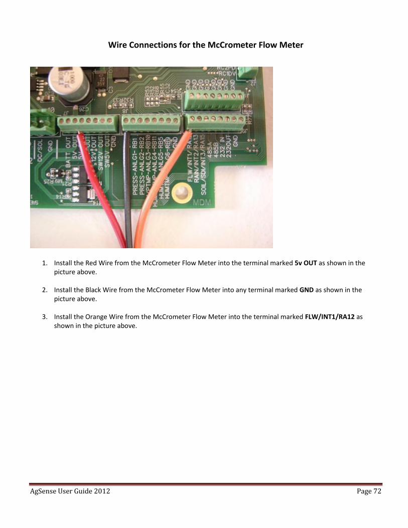
Wire Connections for the McCrometer Flow Meter
1. Install the Red Wire from the McCrometer Flow Meter into the terminal marked 5v OUT as shown in the picture above.
2. Install the Black Wire from the McCrometer Flow Meter into any terminal marked GND as shown in the
picture above.
3. Install the Orange Wire from the McCrometer Flow Meter into the terminal marked FLW/INT1/RA12 as shown in the picture above.
AgSense User Guide 2012 Page 73
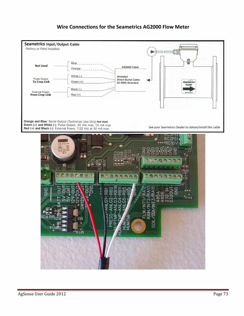
Wire Connections for the Seametrics AG2000 Flow Meter
AgSense User Guide 2012 Page 74
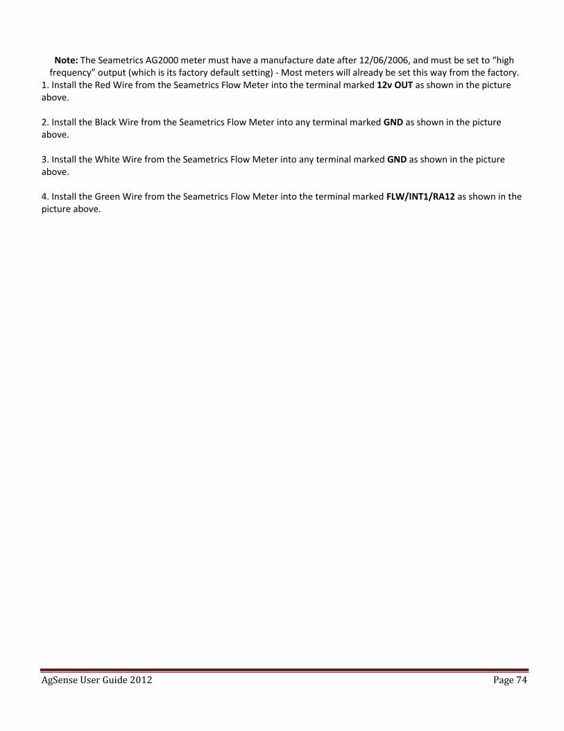
Note: The Seametrics AG2000 meter must have a manufacture date after 12/06/2006, and must be set to “high frequency” output (which is its factory default setting) - Most meters will already be set this way from the factory.
1. Install the Red Wire from the Seametrics Flow Meter into the terminal marked 12v OUT as shown in the picture above. 2. Install the Black Wire from the Seametrics Flow Meter into any terminal marked GND as shown in the picture above. 3. Install the White Wire from the Seametrics Flow Meter into any terminal marked GND as shown in the picture above. 4. Install the Green Wire from the Seametrics Flow Meter into the terminal marked FLW/INT1/RA12 as shown in the picture above.
AgSense User Guide 2012 Page 75
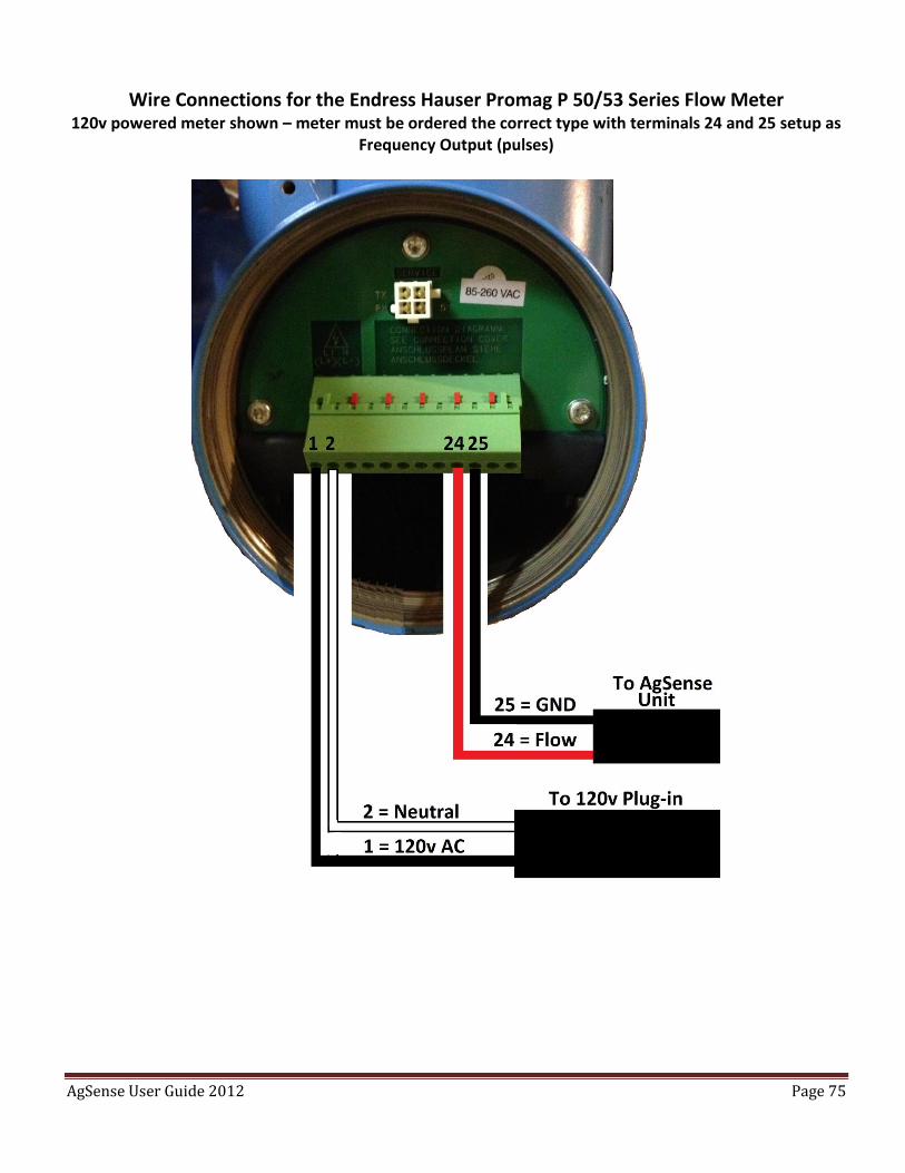
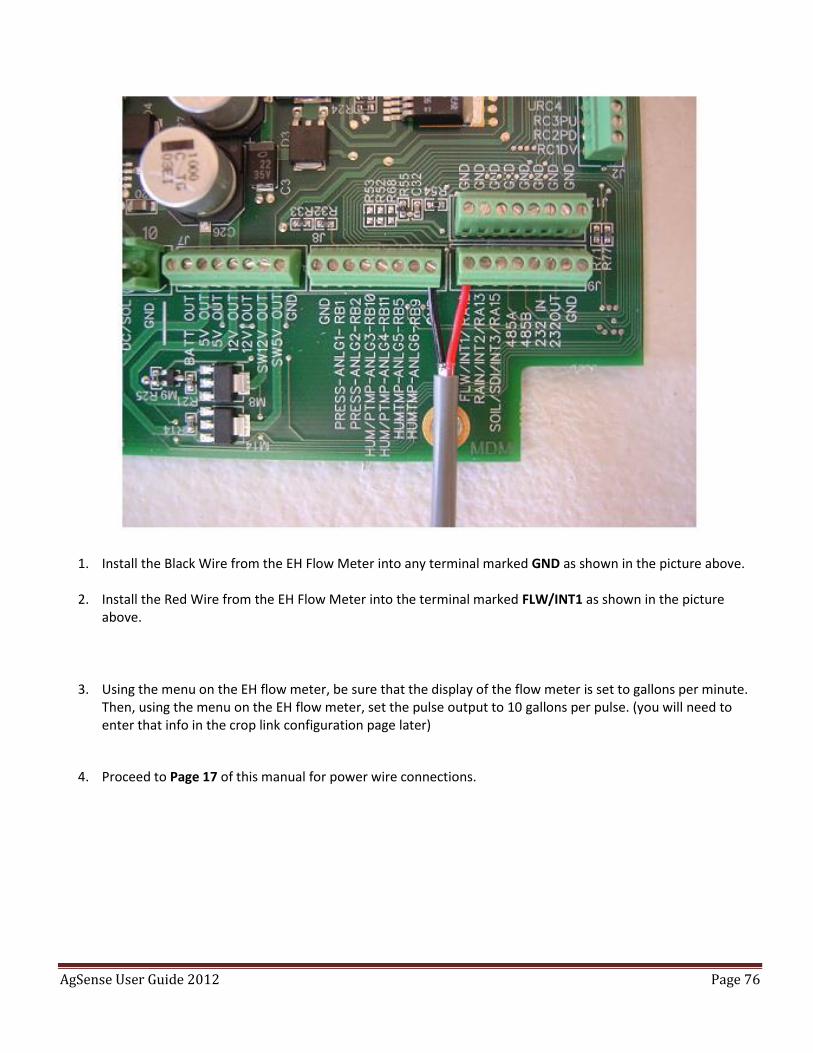
Wire Connections for the Endress Hauser Promag P 50/53 Series Flow Meter 120v powered meter shown – meter must be ordered the correct type with terminals 24 and 25 setup as
Frequency Output (pulses)
AgSense User Guide 2012 Page 76
1. Install the Black Wire from the EH Flow Meter into any terminal marked GND as shown in the picture above.
2. Install the Red Wire from the EH Flow Meter into the terminal marked FLW/INT1 as shown in the picture
above.
3. Using the menu on the EH flow meter, be sure that the display of the flow meter is set to gallons per minute. Then, using the menu on the EH flow meter, set the pulse output to 10 gallons per pulse. (you will need to enter that info in the crop link configuration page later)
4. Proceed to Page 17 of this manual for power wire connections.
AgSense User Guide 2012 Page 77
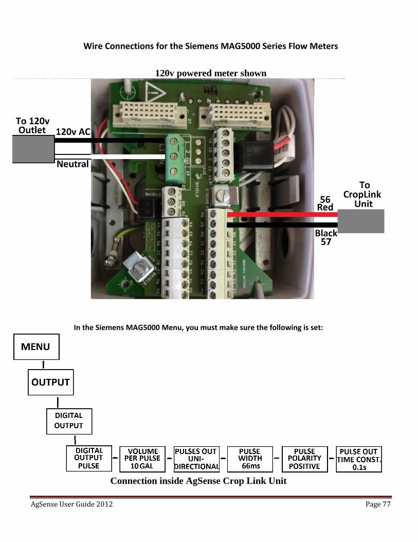
Wire Connections for the Siemens MAG5000 Series Flow Meters
120v powered meter shown
In the Siemens MAG5000 Menu, you must make sure the following is set:
Connection inside AgSense Crop Link Unit

AgSense User Guide 2012 Page 78
1. Install the Black Wire from the Siemens Flow Meter into any terminal marked GND as shown in the picture
above.
2. Install the Red Wire from the Siemens Flow Meter into the terminal marked FLW/INT1 as shown in the picture above.
3. Set the Config on Wagnet for this unit to Siemens, and 10 gallons per pulse.
4. Proceed to Page 17 of this manual for power wire connections.
AgSense User Guide 2012 Page 79
Power and Relay Wiring Instructions:
1. Choose one of these two ways to connect power to the cable that is attached to our box – Note: this unit
must have power to it all the time to calculate flow correctly.
- AC powered units -
Black = 120v Power Input
Brown/Black stripe = Neutral
DC powered units -
Red = 7-40v DC + Power Input
Red/black stripe = DC GND
2. Make sure power switch in the upper left portion of our circuit board is turned on.
3. Once you have power applied to our unit, Call AgSense at 605-352-8350 to have the configuration sent to the unit so it will start to read the flow meter.
4. Also, once power is applied to our unit, the configuration has been sent to the unit, and water is flowing through the pipe, the GPS light in the upper right corner of our circuit board will be blinking.
Optional: This unit has 2 relays that can be used to via the website to remotely control other equipment.
- Relay/Wire Connections -
Relay 1 Common = Blue
Relay 1 Normally Open = Orange
Relay 1 Normally Closed = Yellow
Relay 2 Common = Blue/Black stripe
Relay 2 Normally Open = Orange/Black stripe
Relay 2 Normally Closed = Yellow/Black stripe
AgSense User Guide 2012 Page 80
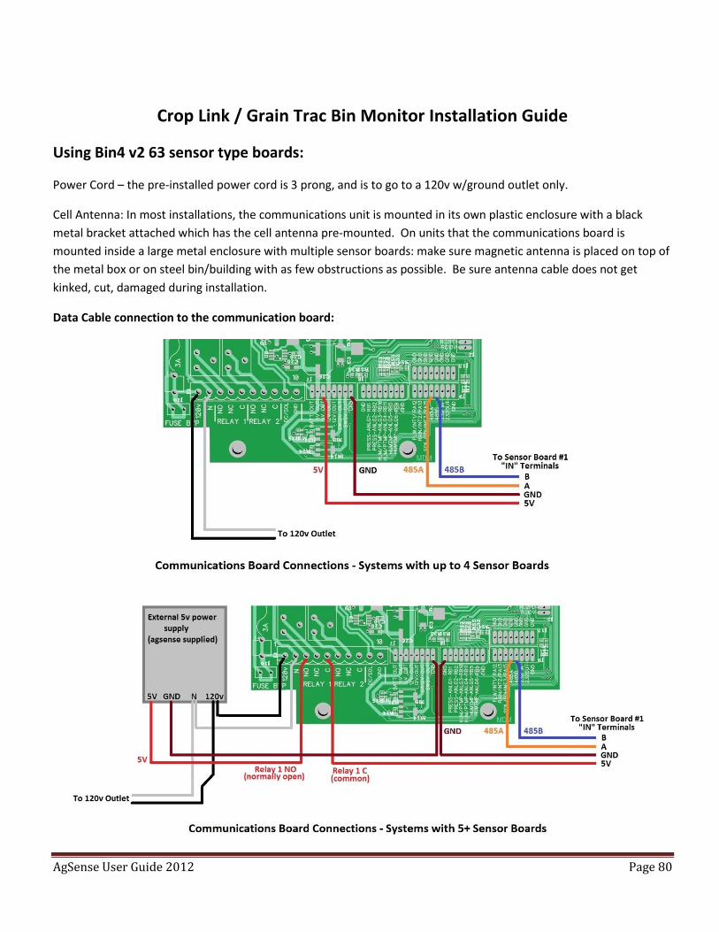
Crop Link / Grain Trac Bin Monitor Installation Guide
Using Bin4 v2 63 sensor type boards:
Power Cord – the pre-installed power cord is 3 prong, and is to go to a 120v w/ground outlet only.
Cell Antenna: In most installations, the communications unit is mounted in its own plastic enclosure with a black
metal bracket attached which has the cell antenna pre-mounted. On units that the communications board is
mounted inside a large metal enclosure with multiple sensor boards: make sure magnetic antenna is placed on top of
the metal box or on steel bin/building with as few obstructions as possible. Be sure antenna cable does not get
kinked, cut, damaged during installation.
Data Cable connection to the communication board:
AgSense User Guide 2012 Page 81
Data Cable between boxes:
In a multiple board system with two or more boxes containing sensor boards, there is a screw terminal strip
in each box labeled “IN” and “OUT” - under each “IN” and “OUT” there are four terminals: “B” “A” “5V” “GND”
Starting at Box 1 - the main unit (the one that contains the communications board and antenna) - connect:
Box 1 “B” to Box 2 “B”
Box 1 “A” to Box 2 “A”
Box 1 “5v” to Box2 “5v”
Box 1 “GND” to Box 2 “GND”
Continue to connect all boxes together in this pattern: Box 2 “OUT” to Box 3 “IN”, Box 3 “OUT to Box 4 “IN”,
etc…
Be sure to use appropriate sized cable between boxes - no smaller than 20 gauge between boxes that have
very few sensor boards are very close together, up to 12 or 10 gauge between all boxes that have more
sensor boards and/or longer distances between boxes. On longer runs, be sure to use shielded cable and/or
conduit to limit electrical noise coming from other equipment.
Connecting Cables to the Sensor Boards:
Be sure to write down on paper how many cables are in each bin, and how many sensors are on each cable
(note: some cables have more wires than actual sensors – **example - some cables have 12 sensor wires, but
only 10 sensors – the two extra wires would not be used or attached to the sensor board – you may need to
check the manufacturers tag on each cable, or ohm test all of the sensor wires to determine how many are
actually connected to sensors)
Also be sure to write down on paper how many cables are installed into each sensor board, what bins those
cables go to, and how many sensors each cable has starting from board 1 sensor 1. We will need all this
information when you call AgSense to have us configure the system to show up on the internet correctly.
Each sensor board can hold a maximum of 63 sensors. It can also hold up to 8 separate cables, but all of those
cables sensors added together cannot exceed the limit of 63 sensors per board.
NOTE: if a sensor board does not have enough positions left to fit the entire cable onto that board, you must
move the entire cable to the next board.
Starting with Bin 1, Cable 1, Sensor 1 (sensor 1 of each cable being the bottom of the bin – see temp cable
color codes in the examples) , start installing the sensor wires into the sensor boards starting at board 1
sensor 1, see examples below.
AgSense User Guide 2012 Page 82
Example 1: 3 cables, 6 sensors each
Cable 1, Sensors 1-6 go into board positions 1-6
Cable 1 common wire goes into position marked “Cable 1” at the top of the board.
Cable 2, Sensors 1-6 go into board positions 7-12
Cable 2 common wire goes into position marked “Cable 2” at the top of the board.
Cable 3, Sensors 1-6 go into board positions 13-18
Cable 3 common wire goes into position marked “Cable 3” at the top of the board.
NOTE: If a cable has more than 1 common/constantan wire, (like some
thermocouple cables) all of the common/constantan wires for each individual
cable go into the same “Cable” terminal at the top of the board.
AgSense User Guide 2012 Page 83
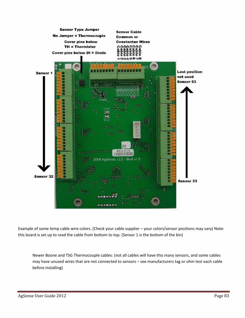
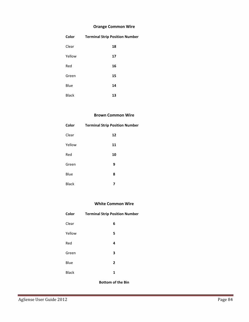
Example of some temp cable wire colors. (Check your cable supplier – your colors/sensor positions may vary) Note:
this board is set up to read the cable from bottom to top. (Sensor 1 is the bottom of the bin)
Newer Boone and TSG Thermocouple cables: (not all cables will have this many sensors, and some cables
may have unused wires that are not connected to sensors – see manufacturers tag or ohm test each cable
before installing)
AgSense User Guide 2012 Page 84
Orange Common Wire
Color Terminal Strip Position Number
Clear 18
Yellow 17
Red 16
Green 15
Blue 14
Black 13
Brown Common Wire
Color Terminal Strip Position Number
Clear 12
Yellow 11
Red 10
Green 9
Blue 8
Black 7
White Common Wire
Color Terminal Strip Position Number
Clear 6
Yellow 5
Red 4
Green 3
Blue 2
Black 1
Bottom of the Bin
AgSense User Guide 2012 Page 85
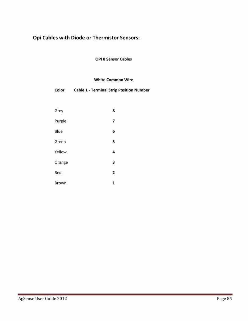
Opi Cables with Diode or Thermistor Sensors:
OPI 8 Sensor Cables
White Common Wire
Color Cable 1 - Terminal Strip Position Number
Grey 8
Purple 7
Blue 6
Green 5
Yellow 4
Orange 3
Red 2
Brown 1
AgSense User Guide 2012 Page 86
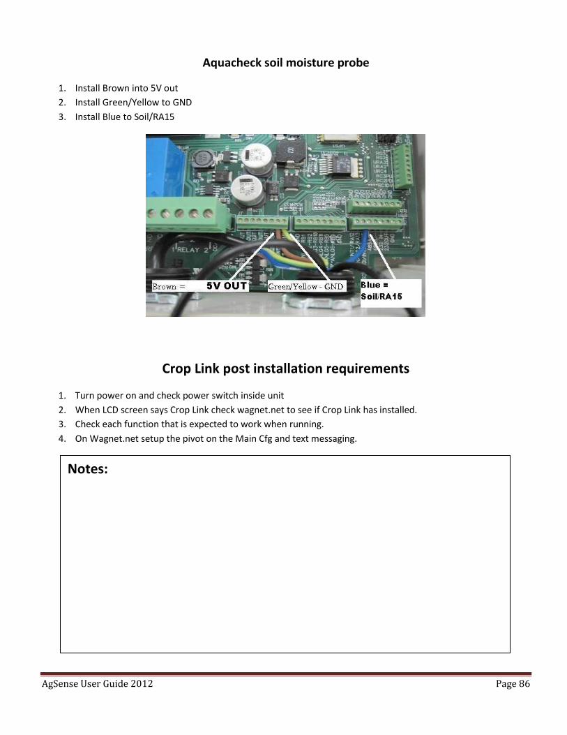
Aquacheck soil moisture probe
1. Install Brown into 5V out
2. Install Green/Yellow to GND
3. Install Blue to Soil/RA15
Crop Link post installation requirements
1. Turn power on and check power switch inside unit
2. When LCD screen says Crop Link check wagnet.net to see if Crop Link has installed.
3. Check each function that is expected to work when running.
4. On Wagnet.net setup the pivot on the Main Cfg and text messaging.
Notes:
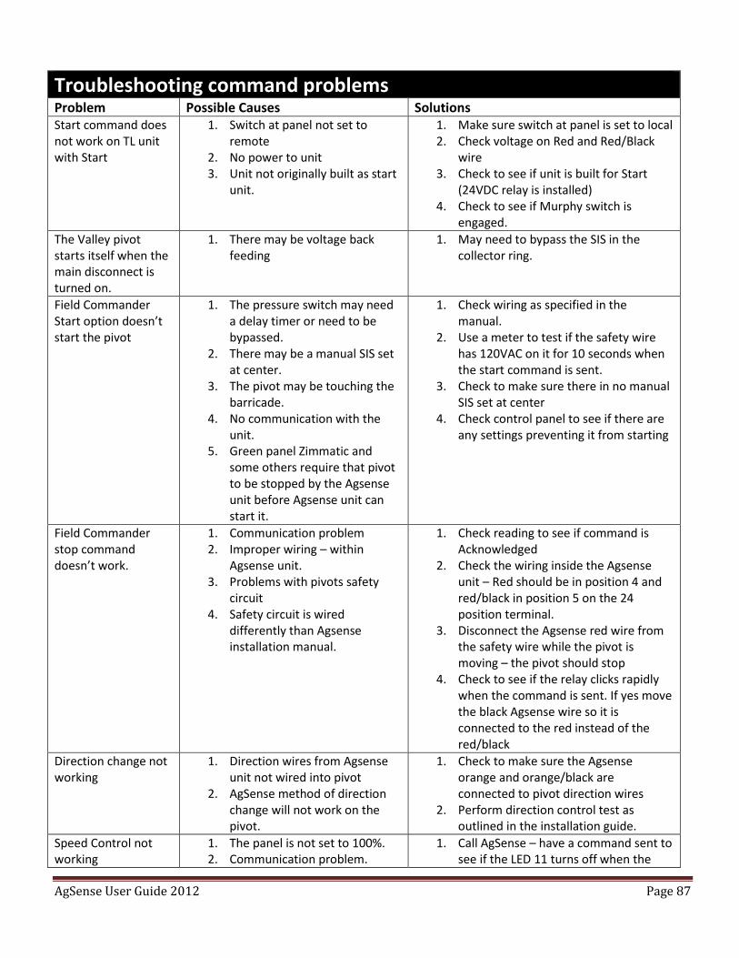
AgSense User Guide 2012 Page 87
Troubleshooting command problems
Problem Possible Causes Solutions Start command does not work on TL unit with Start
1. Switch at panel not set to remote
2. No power to unit 3. Unit not originally built as start
unit.
1. Make sure switch at panel is set to local 2. Check voltage on Red and Red/Black
wire 3. Check to see if unit is built for Start
(24VDC relay is installed) 4. Check to see if Murphy switch is
engaged.
The Valley pivot starts itself when the main disconnect is turned on.
1. There may be voltage back feeding
1. May need to bypass the SIS in the collector ring.
Field Commander Start option doesn’t start the pivot
1. The pressure switch may need a delay timer or need to be bypassed.
2. There may be a manual SIS set at center.
3. The pivot may be touching the barricade.
4. No communication with the unit.
5. Green panel Zimmatic and some others require that pivot to be stopped by the Agsense unit before Agsense unit can start it.
1. Check wiring as specified in the manual.
2. Use a meter to test if the safety wire has 120VAC on it for 10 seconds when the start command is sent.
3. Check to make sure there in no manual SIS set at center
4. Check control panel to see if there are any settings preventing it from starting
Field Commander stop command doesn’t work.
1. Communication problem 2. Improper wiring – within
Agsense unit. 3. Problems with pivots safety
circuit 4. Safety circuit is wired
differently than Agsense installation manual.
1. Check reading to see if command is Acknowledged
2. Check the wiring inside the Agsense unit – Red should be in position 4 and red/black in position 5 on the 24 position terminal.
3. Disconnect the Agsense red wire from the safety wire while the pivot is moving – the pivot should stop
4. Check to see if the relay clicks rapidly when the command is sent. If yes move the black Agsense wire so it is connected to the red instead of the red/black
Direction change not working
1. Direction wires from Agsense unit not wired into pivot
2. AgSense method of direction change will not work on the pivot.
1. Check to make sure the Agsense orange and orange/black are connected to pivot direction wires
2. Perform direction control test as outlined in the installation guide.
Speed Control not working
1. The panel is not set to 100%. 2. Communication problem.
1. Call AgSense – have a command sent to see if the LED 11 turns off when the
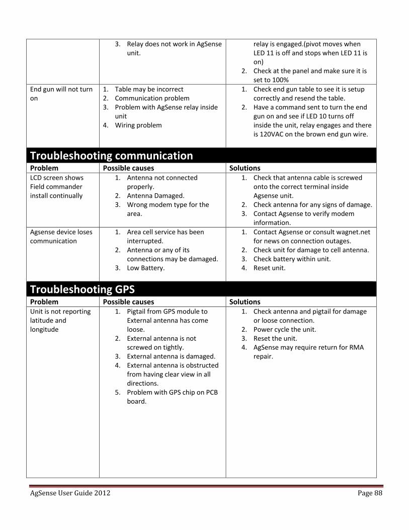
AgSense User Guide 2012 Page 88
3. Relay does not work in AgSense unit.
relay is engaged.(pivot moves when LED 11 is off and stops when LED 11 is on)
2. Check at the panel and make sure it is set to 100%
End gun will not turn on
1. Table may be incorrect 2. Communication problem 3. Problem with AgSense relay inside
unit 4. Wiring problem
1. Check end gun table to see it is setup correctly and resend the table.
2. Have a command sent to turn the end gun on and see if LED 10 turns off inside the unit, relay engages and there is 120VAC on the brown end gun wire.
Troubleshooting communication
Problem Possible causes Solutions LCD screen shows Field commander install continually
1. Antenna not connected properly.
2. Antenna Damaged. 3. Wrong modem type for the
area.
1. Check that antenna cable is screwed onto the correct terminal inside Agsense unit.
2. Check antenna for any signs of damage. 3. Contact Agsense to verify modem
information.
Agsense device loses communication
1. Area cell service has been interrupted.
2. Antenna or any of its connections may be damaged.
3. Low Battery.
1. Contact Agsense or consult wagnet.net for news on connection outages.
2. Check unit for damage to cell antenna. 3. Check battery within unit. 4. Reset unit.
Troubleshooting GPS Problem Possible causes Solutions Unit is not reporting latitude and longitude
1. Pigtail from GPS module to External antenna has come loose.
2. External antenna is not screwed on tightly.
3. External antenna is damaged. 4. External antenna is obstructed
from having clear view in all directions.
5. Problem with GPS chip on PCB board.
1. Check antenna and pigtail for damage or loose connection.
2. Power cycle the unit. 3. Reset the unit. 4. AgSense may require return for RMA
repair.
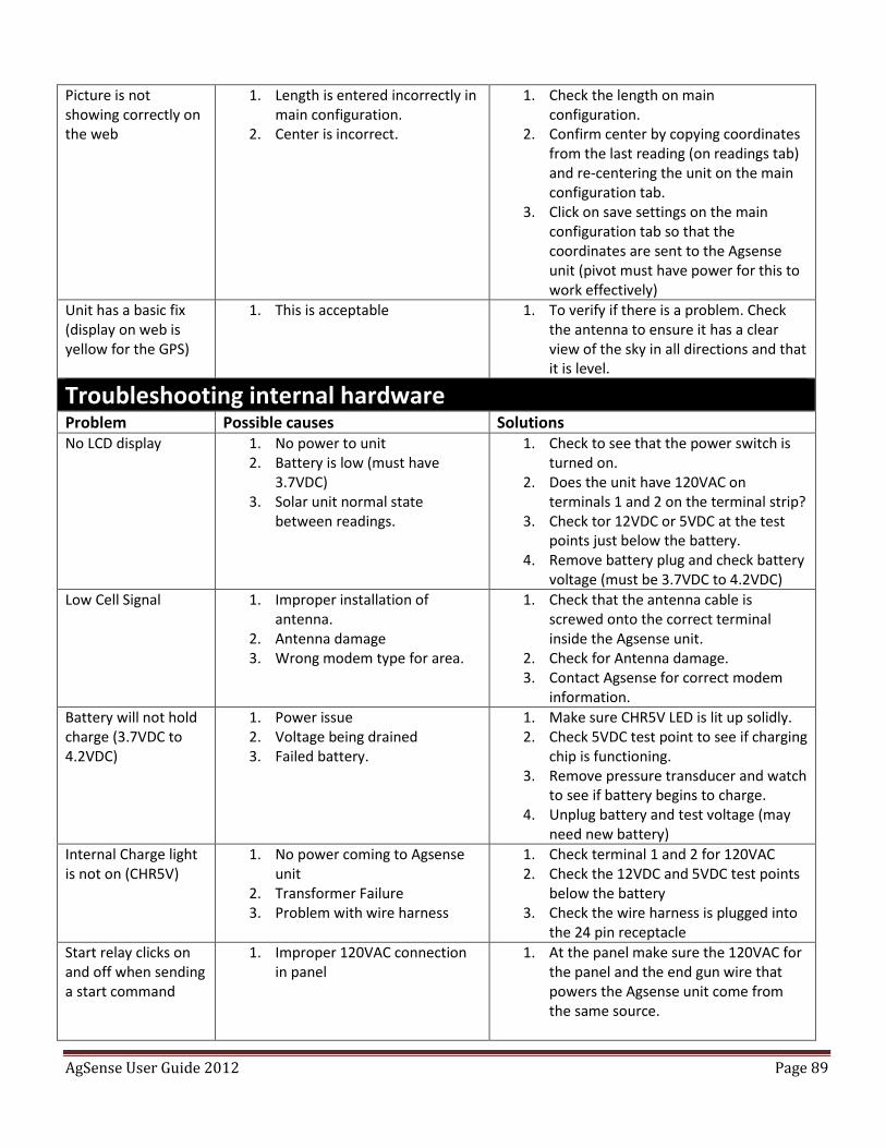
AgSense User Guide 2012 Page 89
Picture is not showing correctly on the web
1. Length is entered incorrectly in main configuration.
2. Center is incorrect.
1. Check the length on main configuration.
2. Confirm center by copying coordinates from the last reading (on readings tab) and re-centering the unit on the main configuration tab.
3. Click on save settings on the main configuration tab so that the coordinates are sent to the Agsense unit (pivot must have power for this to work effectively)
Unit has a basic fix (display on web is yellow for the GPS)
1. This is acceptable 1. To verify if there is a problem. Check the antenna to ensure it has a clear view of the sky in all directions and that it is level.
Troubleshooting internal hardware Problem Possible causes Solutions No LCD display 1. No power to unit
2. Battery is low (must have 3.7VDC)
3. Solar unit normal state between readings.
1. Check to see that the power switch is turned on.
2. Does the unit have 120VAC on terminals 1 and 2 on the terminal strip?
3. Check tor 12VDC or 5VDC at the test points just below the battery.
4. Remove battery plug and check battery voltage (must be 3.7VDC to 4.2VDC)
Low Cell Signal 1. Improper installation of antenna.
2. Antenna damage 3. Wrong modem type for area.
1. Check that the antenna cable is screwed onto the correct terminal inside the Agsense unit.
2. Check for Antenna damage. 3. Contact Agsense for correct modem
information.
Battery will not hold charge (3.7VDC to 4.2VDC)
1. Power issue 2. Voltage being drained 3. Failed battery.
1. Make sure CHR5V LED is lit up solidly. 2. Check 5VDC test point to see if charging
chip is functioning. 3. Remove pressure transducer and watch
to see if battery begins to charge. 4. Unplug battery and test voltage (may
need new battery)
Internal Charge light is not on (CHR5V)
1. No power coming to Agsense unit
2. Transformer Failure 3. Problem with wire harness
1. Check terminal 1 and 2 for 120VAC 2. Check the 12VDC and 5VDC test points
below the battery 3. Check the wire harness is plugged into
the 24 pin receptacle
Start relay clicks on and off when sending a start command
1. Improper 120VAC connection in panel
1. At the panel make sure the 120VAC for the panel and the end gun wire that powers the Agsense unit come from the same source.
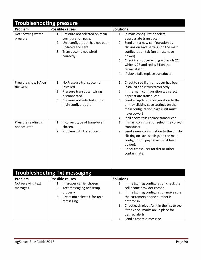
AgSense User Guide 2012 Page 90
Troubleshooting pressure Problem Possible causes Solutions Not showing water pressure
1. Pressure not selected on main configuration page.
2. Unit configuration has not been updated and sent.
3. Transducer is not wired correctly.
1. In main configuration select appropriate transducer
2. Send unit a new configuration by clicking on save settings on the main configuration tab (unit must have power)
3. Check transducer wiring – black is 22, white is 23 and red is 24 on the terminal strip.
4. If above fails replace transducer.
Pressure show NA on the web
1. No Pressure transducer is installed.
2. Pressure transducer wiring disconnected.
3. Pressure not selected in the main configuration.
1. Check to see if a transducer has been installed and is wired correctly.
2. In the main configuration tab select appropriate transducer
3. Send an updated configuration to the unit by clicking save settings on the main configuration page (unit must have power)
4. If all above fails replace transducer.
Pressure reading is not accurate
1. Incorrect type of transducer chosen.
2. Problem with transducer.
1. In main configuration select the correct transducer.
2. Send a new configuration to the unit by clicking on save settings on the main configuration page (unit must have power).
3. Check transducer for dirt or other contaminate.
Troubleshooting Txt messaging Problem Possible causes Solutions Not receiving text messages
1. Improper carrier chosen 2. Text messaging not setup
properly 3. Pivots not selected for text
messaging.
1. In the txt msg configuration check the cell phone provider chosen.
2. In the txt msg configuration make sure the customers phone number is entered in.
3. Check each pivot /unit in the list to see if the check marks are in place for desired alerts
4. Send a test text message.
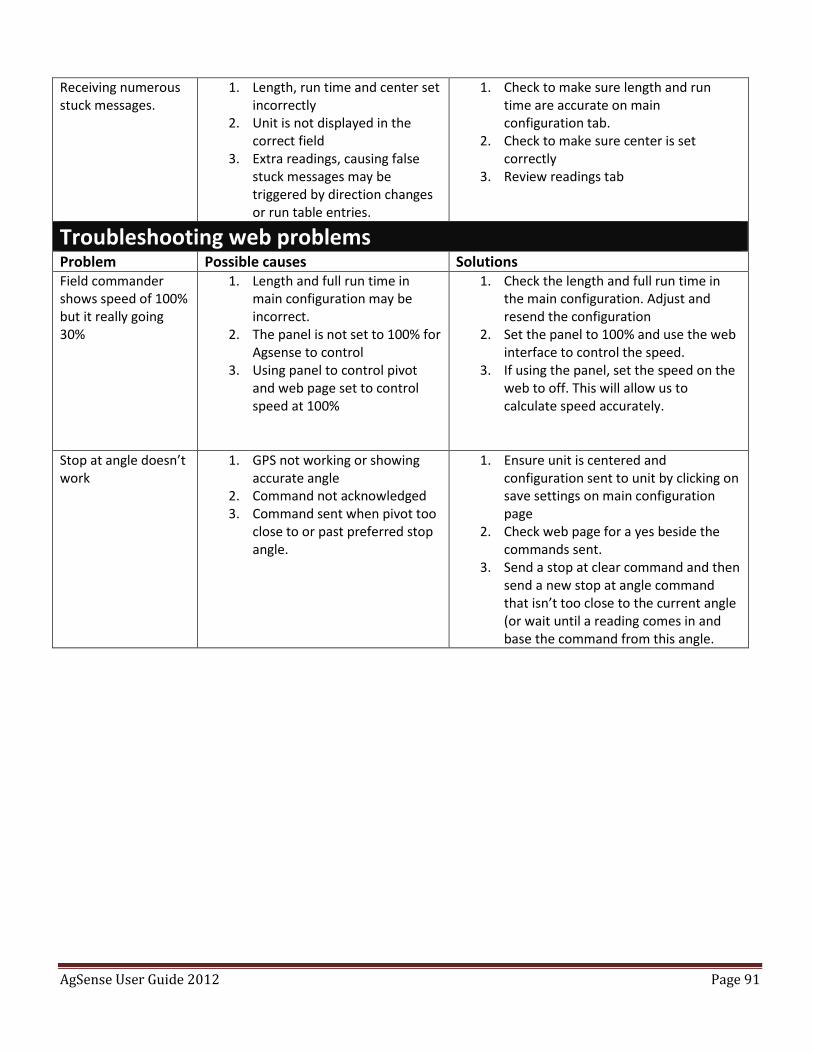
AgSense User Guide 2012 Page 91
Receiving numerous stuck messages.
1. Length, run time and center set incorrectly
2. Unit is not displayed in the correct field
3. Extra readings, causing false stuck messages may be triggered by direction changes or run table entries.
1. Check to make sure length and run time are accurate on main configuration tab.
2. Check to make sure center is set correctly
3. Review readings tab
Troubleshooting web problems Problem Possible causes Solutions Field commander shows speed of 100% but it really going 30%
1. Length and full run time in main configuration may be incorrect.
2. The panel is not set to 100% for Agsense to control
3. Using panel to control pivot and web page set to control speed at 100%
1. Check the length and full run time in the main configuration. Adjust and resend the configuration
2. Set the panel to 100% and use the web interface to control the speed.
3. If using the panel, set the speed on the web to off. This will allow us to calculate speed accurately.
Stop at angle doesn’t work
1. GPS not working or showing accurate angle
2. Command not acknowledged 3. Command sent when pivot too
close to or past preferred stop angle.
1. Ensure unit is centered and configuration sent to unit by clicking on save settings on main configuration page
2. Check web page for a yes beside the commands sent.
3. Send a stop at clear command and then send a new stop at angle command that isn’t too close to the current angle (or wait until a reading comes in and base the command from this angle.
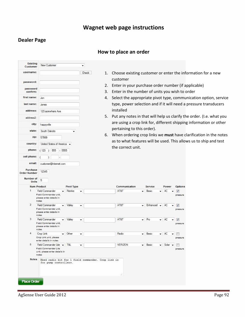
AgSense User Guide 2012 Page 92
Wagnet web page instructions
Dealer Page
How to place an order
1. Choose existing customer or enter the information for a new
customer
2. Enter in your purchase order number (if applicable)
3. Enter in the number of units you wish to order
4. Select the appropriate pivot type, communication option, service
type, power selection and if it will need a pressure transducers
installed
5. Put any notes in that will help us clarify the order. (I.e. what you
are using a crop link for, different shipping information or other
pertaining to this order).
6. When ordering crop links we must have clarification in the notes
as to what features will be used. This allows us to ship and test
the correct unit.
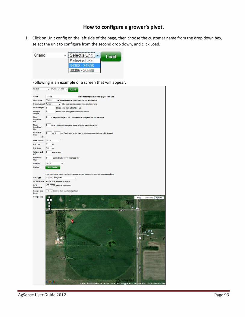
AgSense User Guide 2012 Page 93
How to configure a grower’s pivot.
1. Click on Unit config on the left side of the page, then choose the customer name from the drop down box,
select the unit to configure from the second drop down, and click Load.
Following is an example of a screen that will appear.
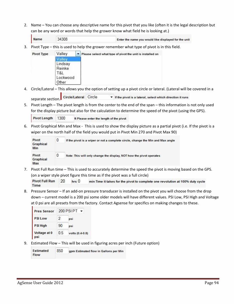
AgSense User Guide 2012 Page 94
2. Name – You can choose any descriptive name for this pivot that you like (often it is the legal description but
can be any word or words that help the grower know what field he is looking at.)
3. Pivot Type – this is used to help the grower remember what type of pivot is in this field.
4. Circle/Lateral – This allows you the option of setting up a pivot circle or lateral. (Lateral will be covered in a
separate section.
5. Pivot Length – The pivot length is from the center to the end of the span – this information is not only used
for the display picture but also for the calculation to determine the speed of the pivot (using the GPS).
6. Pivot Graphical Min and Max - This is used to show the display picture as a partial pivot (i.e. If the pivot is a
wiper on the north half of the field you would put in Pivot Min 270 and Pivot Max 90)
7. Pivot Full Run time – This is used to accurately determine the speed the pivot is moving based on the GPS.
(on a wiper style pivot figure this time as if the pivot was a full circle)
8. Pressure Sensor – If an add-on pressure transducer is installed on the pivot you will choose from the drop
down – current model is a 200 psi some older models will have different values. PSI Low, PSI High and Voltage
at 0 psi are all presets from the factory. Contact Agsense for specifics on making changes to these.
9. Estimated Flow – This will be used in figuring acres per inch (Future option)
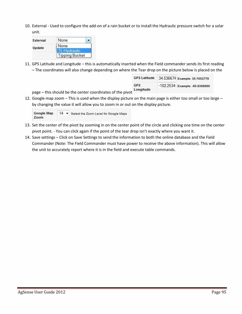
AgSense User Guide 2012 Page 95
10. External - Used to configure the add-on of a rain bucket or to install the Hydraulic pressure switch for a solar
unit.
11. GPS Latitude and Longitude – this is automatically inserted when the Field commander sends its first reading
– The coordinates will also change depending on where the Tear drop on the picture below is placed on the
page – this should be the center coordinates of the pivot
12. Google map zoom – This is used when the display picture on the main page is either too small or too large –
by changing the value it will allow you to zoom in or out on the display picture.
13. Set the center of the pivot by zooming in on the center point of the circle and clicking one time on the center
pivot point. - You can click again if the point of the tear drop isn’t exactly where you want it.
14. Save settings – Click on Save Settings to send the information to both the online database and the Field
Commander (Note: The Field Commander must have power to receive the above information). This will allow
the unit to accurately report where it is in the field and execute table commands.
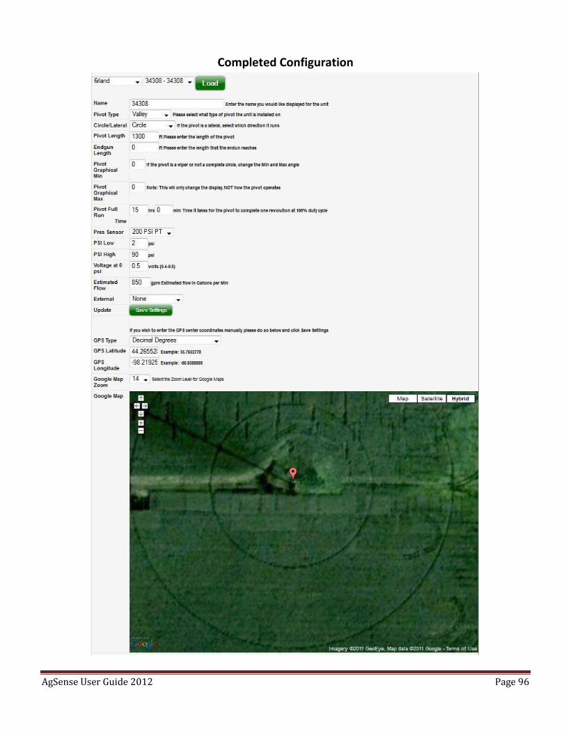
AgSense User Guide 2012 Page 96
Completed Configuration
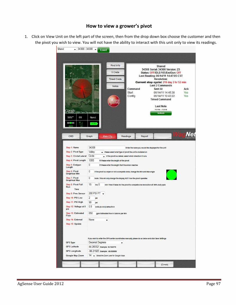
AgSense User Guide 2012 Page 97
How to view a grower’s pivot
1. Click on View Unit on the left part of the screen, then from the drop down box choose the customer and then
the pivot you wish to view. You will not have the ability to interact with this unit only to view its readings.
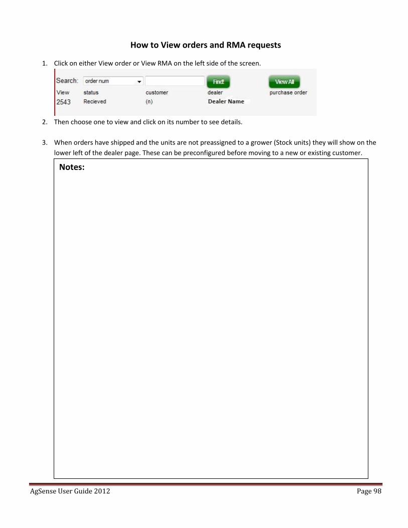
AgSense User Guide 2012 Page 98
How to View orders and RMA requests
1. Click on either View order or View RMA on the left side of the screen.
2. Then choose one to view and click on its number to see details.
3. When orders have shipped and the units are not preassigned to a grower (Stock units) they will show on the
lower left of the dealer page. These can be preconfigured before moving to a new or existing customer.
Notes:
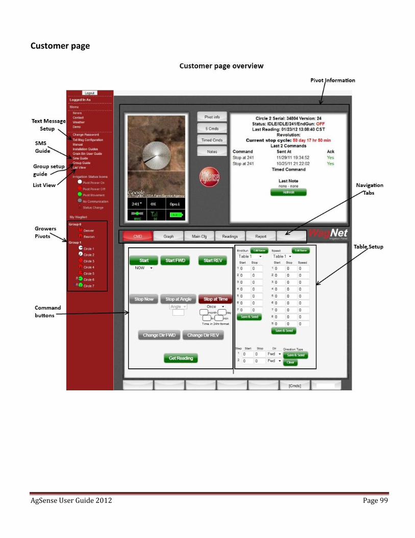
AgSense User Guide 2012 Page 99
Customer page
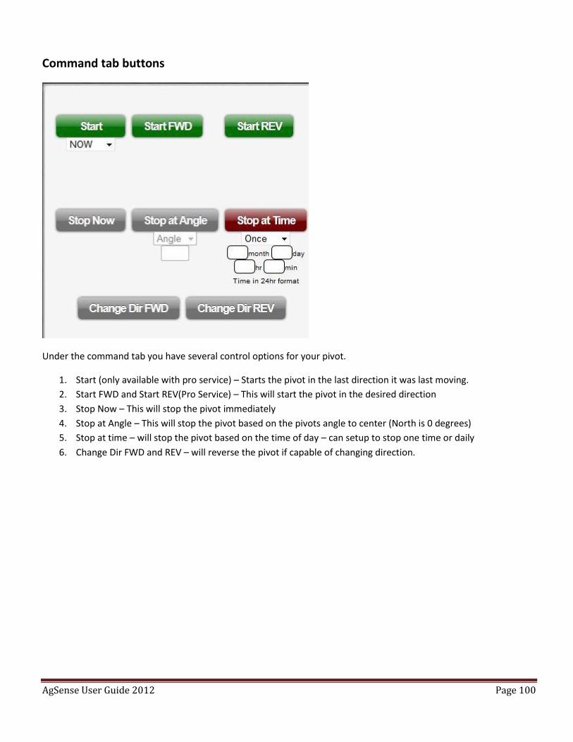
AgSense User Guide 2012 Page 100
Command tab buttons
Under the command tab you have several control options for your pivot.
1. Start (only available with pro service) – Starts the pivot in the last direction it was last moving.
2. Start FWD and Start REV(Pro Service) – This will start the pivot in the desired direction
3. Stop Now – This will stop the pivot immediately
4. Stop at Angle – This will stop the pivot based on the pivots angle to center (North is 0 degrees)
5. Stop at time – will stop the pivot based on the time of day – can setup to stop one time or daily
6. Change Dir FWD and REV – will reverse the pivot if capable of changing direction.
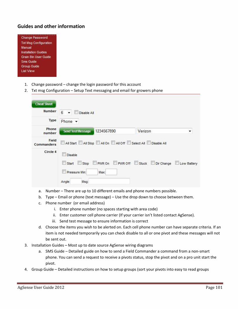
AgSense User Guide 2012 Page 101
Guides and other information
1. Change password – change the login password for this account
2. Txt msg Configuration – Setup Text messaging and email for growers phone
a. Number – There are up to 10 different emails and phone numbers possible.
b. Type – Email or phone (text message) – Use the drop down to choose between them.
c. Phone number (or email address)
i. Enter phone number (no spaces starting with area code)
ii. Enter customer cell phone carrier (If your carrier isn’t listed contact AgSense).
iii. Send test message to ensure information is correct
d. Choose the items you wish to be alerted on. Each cell phone number can have separate criteria. If an
item is not needed temporarily you can check disable to all or one pivot and these messages will not
be sent out.
3. Installation Guides – Most up to date source AgSense wiring diagrams
a. SMS Guide – Detailed guide on how to send a Field Commander a command from a non-smart
phone. You can send a request to receive a pivots status, stop the pivot and on a pro unit start the
pivot.
4. Group Guide – Detailed instructions on how to setup groups (sort your pivots into easy to read groups
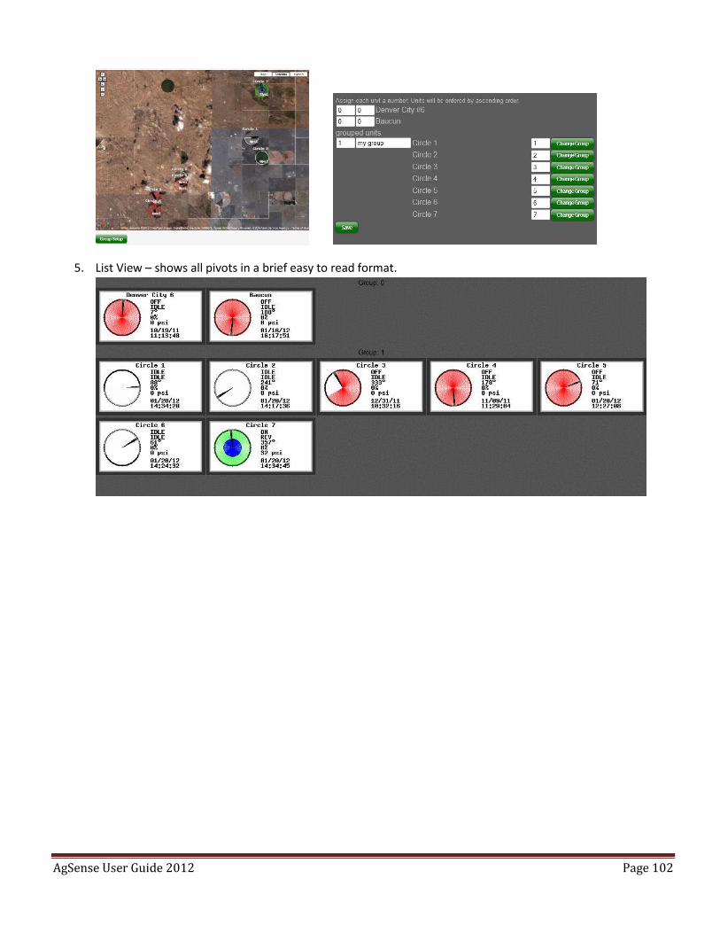
AgSense User Guide 2012 Page 102
5. List View – shows all pivots in a brief easy to read format.
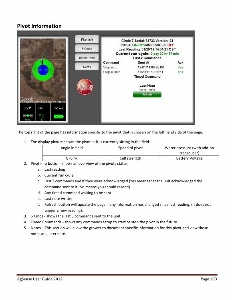
AgSense User Guide 2012 Page 103
Pivot Information
The top right of the page has information specific to the pivot that is chosen on the left hand side of the page.
1. The display picture shows the pivot as it is currently sitting in the field.
Angle in field Speed of pivot Water pressure (with add-on transducer)
GPS fix Cell strength Battery Voltage
2. Pivot info button- shows an overview of the pivots status,
a. Last reading
b. Current run cycle
c. Last 2 commands and if they were acknowledged (Yes means that the unit acknowledged the
command sent to it, No means you should resend)
d. Any timed command waiting to be sent
e. Last note written
f. Refresh button will update the page if any information has changed since last reading. (It does not
trigger a new reading).
3. 5 Cmds - shows the last 5 commands sent to the unit
4. Timed Commands - shows any commands setup to start or stop the pivot in the future
5. Notes – This section will allow the grower to document specific information for this pivot and view those
notes at a later date.
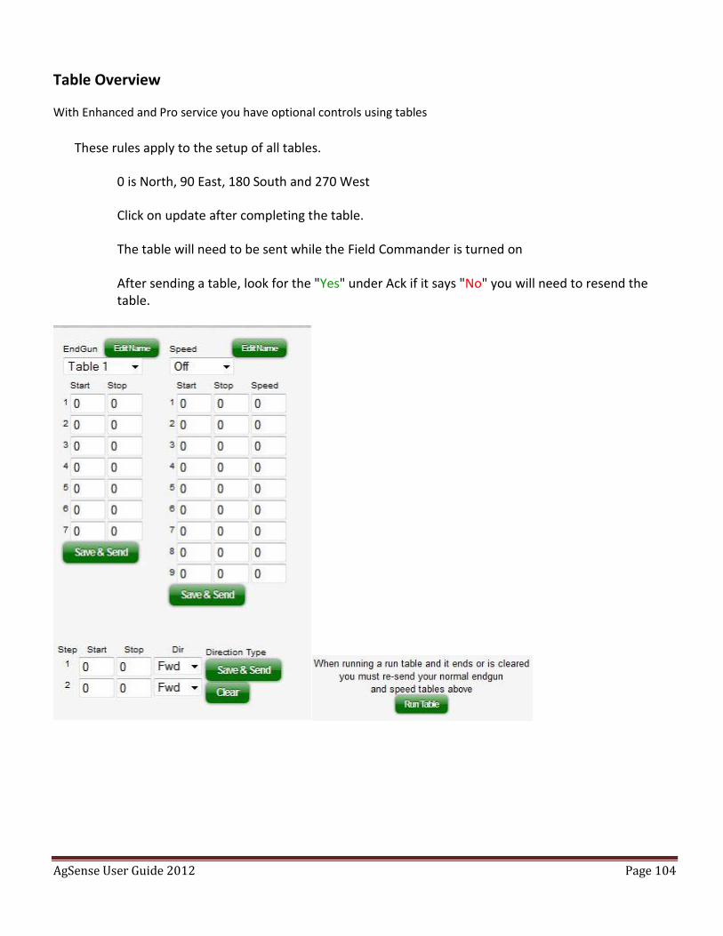
AgSense User Guide 2012 Page 104
Table Overview
With Enhanced and Pro service you have optional controls using tables
These rules apply to the setup of all tables.
0 is North, 90 East, 180 South and 270 West
Click on update after completing the table.
The table will need to be sent while the Field Commander is turned on
After sending a table, look for the "Yes" under Ack if it says "No" you will need to resend the table.
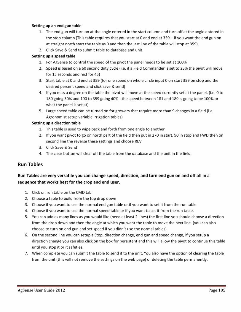
AgSense User Guide 2012 Page 105
Setting up an end gun table
1. The end gun will turn on at the angle entered in the start column and turn off at the angle entered in
the stop column (This table requires that you start at 0 and end at 359 – if you want the end gun on
at straight north start the table as 0 and then the last line of the table will stop at 359)
2. Click Save & Send to submit table to database and unit.
Setting up a speed table
1. For AgSense to control the speed of the pivot the panel needs to be set at 100%
2. Speed is based on a 60 second duty cycle (i.e. if a Field Commander is set to 25% the pivot will move
for 15 seconds and rest for 45)
3. Start table at 0 and end at 359 (for one speed on whole circle input 0 on start 359 on stop and the
desired percent speed and click save & send)
4. If you miss a degree on the table the pivot will move at the speed currently set at the panel. (i.e. 0 to
180 going 30% and 190 to 359 going 40% - the speed between 181 and 189 is going to be 100% or
what the panel is set at)
5. Large speed table can be turned on for growers that require more than 9 changes in a field (i.e.
Agronomist setup variable irrigation tables)
Setting up a direction table
1. This table is used to wipe back and forth from one angle to another
2. If you want pivot to go on north part of the field then put in 270 in start, 90 in stop and FWD then on
second line the reverse these settings and choose REV
3. Click Save & Send
4. The clear button will clear off the table from the database and the unit in the field.
Run Tables
Run Tables are very versatile you can change speed, direction, and turn end gun on and off all in a
sequence that works best for the crop and end user.
1. Click on run table on the CMD tab
2. Choose a table to build from the top drop down
3. Choose if you want to use the normal end gun table or if you want to set it from the run table
4. Choose if you want to use the normal speed table or if you want to set it from the run table.
5. You can add as many lines as you would like (need at least 2 lines) the first line you should choose a direction
from the drop down and then the angle at which you want the table to move the next line. (you can also
choose to turn on end gun and set speed if you didn’t use the normal tables)
6. On the second line you can setup a Stop, direction change, end gun and speed change, if you setup a
direction change you can also click on the box for persistent and this will allow the pivot to continue this table
until you stop it or it safeties.
7. When complete you can submit the table to send it to the unit. You also have the option of clearing the table
from the unit (this will not remove the settings on the web page) or deleting the table permanently.
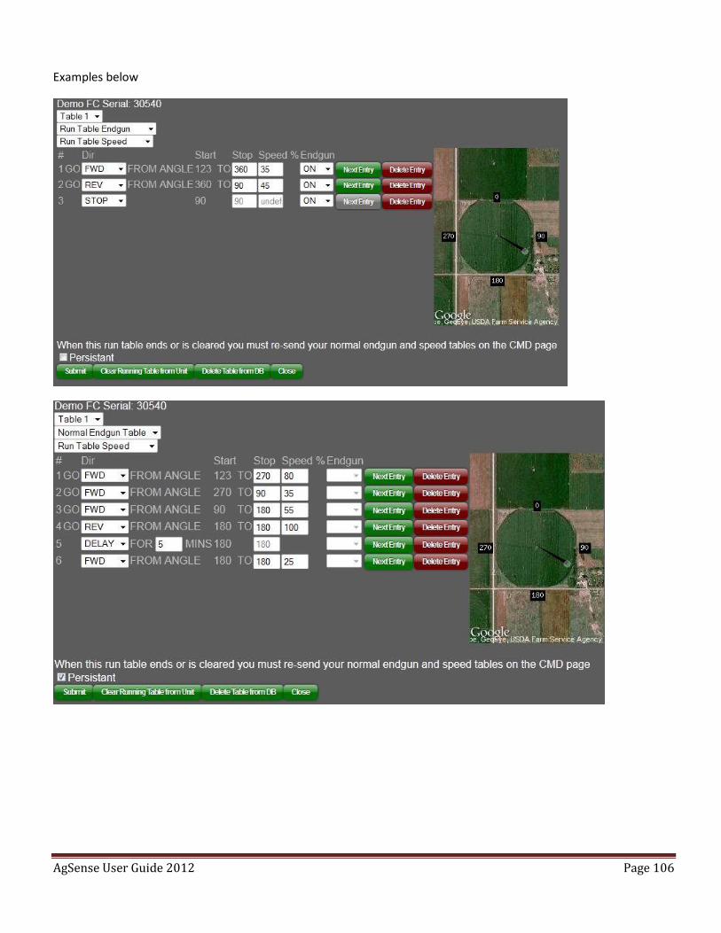
AgSense User Guide 2012 Page 106
Examples below
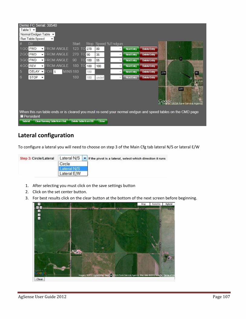
AgSense User Guide 2012 Page 107
Lateral configuration
To configure a lateral you will need to choose on step 3 of the Main Cfg tab lateral N/S or lateral E/W
1. After selecting you must click on the save settings button
2. Click on the set center button.
3. For best results click on the clear button at the bottom of the next screen before beginning.
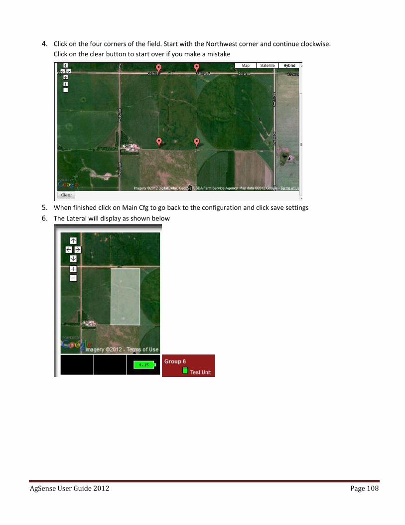
AgSense User Guide 2012 Page 108
4. Click on the four corners of the field. Start with the Northwest corner and continue clockwise.
Click on the clear button to start over if you make a mistake
5. When finished click on Main Cfg to go back to the configuration and click save settings
6. The Lateral will display as shown below
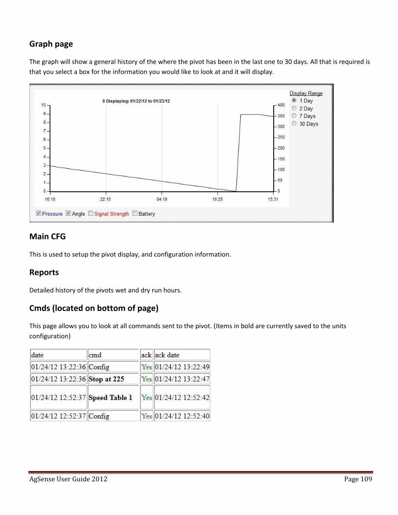
AgSense User Guide 2012 Page 109
Graph page
The graph will show a general history of the where the pivot has been in the last one to 30 days. All that is required is
that you select a box for the information you would like to look at and it will display.
Main CFG
This is used to setup the pivot display, and configuration information.
Reports
Detailed history of the pivots wet and dry run hours.
Cmds (located on bottom of page)
This page allows you to look at all commands sent to the pivot. (Items in bold are currently saved to the units
configuration)
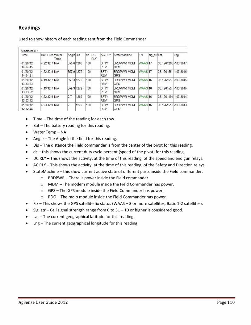
AgSense User Guide 2012 Page 110
Readings
Used to show history of each reading sent from the Field Commander
Time – The time of the reading for each row.
Bat – The battery reading for this reading.
Water Temp – NA
Angle – The Angle in the field for this reading.
Dis – The distance the Field commander is from the center of the pivot for this reading.
dc – this shows the current duty cycle percent (speed of the pivot) for this reading.
DC RLY – This shows the activity, at the time of this reading, of the speed and end gun relays.
AC RLY – This shows the activity, at the time of this reading, of the Safety and Direction relays.
StateMachine – this show current active state of different parts inside the Field commander.
o BRDPWR – There is power inside the Field commander
o MDM – The modem module inside the Field Commander has power.
o GPS – The GPS module inside the Field Commander has power.
o RDO – The radio module inside the Field Commander has power.
Fix – This shows the GPS satellite fix status (WAAS – 3 or more satellites, Basic 1-2 satellites).
Sig_str – Cell signal strength range from 0 to 31 – 10 or higher is considered good.
Lat – The current geographical latitude for this reading.
Lng – The current geographical longitude for this reading.
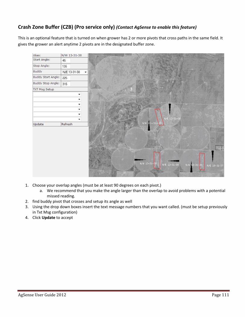
AgSense User Guide 2012 Page 111
Crash Zone Buffer (CZB) (Pro service only) (Contact AgSense to enable this feature)
This is an optional feature that is turned on when grower has 2 or more pivots that cross paths in the same field. It
gives the grower an alert anytime 2 pivots are in the designated buffer zone.
1. Choose your overlap angles (must be at least 90 degrees on each pivot.) a. We recommend that you make the angle larger than the overlap to avoid problems with a potential
missed reading. 2. find buddy pivot that crosses and setup its angle as well 3. Using the drop down boxes insert the text message numbers that you want called. (must be setup previously
in Txt Msg configuration) 4. Click Update to accept
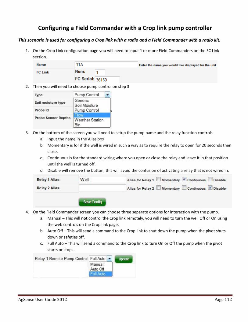
AgSense User Guide 2012 Page 112
Configuring a Field Commander with a Crop link pump controller
This scenario is used for configuring a Crop link with a radio and a Field Commander with a radio kit.
1. On the Crop Link configuration page you will need to input 1 or more Field Commanders on the FC Link
section.
2. Then you will need to choose pump control on step 3
3. On the bottom of the screen you will need to setup the pump name and the relay function controls
a. Input the name in the Alias box
b. Momentary is for if the well is wired in such a way as to require the relay to open for 20 seconds then
close.
c. Continuous is for the standard wiring where you open or close the relay and leave it in that position
until the well is turned off.
d. Disable will remove the button; this will avoid the confusion of activating a relay that is not wired in.
4. On the Field Commander screen you can choose three separate options for interaction with the pump.
a. Manual – This will not control the Crop link remotely, you will need to turn the well Off or On using
the web controls on the Crop link page.
b. Auto Off – This will send a command to the Crop link to shut down the pump when the pivot shuts
down or safeties off.
c. Full Auto – This will send a command to the Crop link to turn On or Off the pump when the pivot
starts or stops.
AgSense User Guide 2012 Page 113
Appendix
Tools and Equipment
It is recommended, when installing or working on and AgSense Field Commander, Crop Link or Grain Trac, that the
following equipment be taken to the field.
Phillips screwdriver (#2)
Standard screwdriver (1/8 x 3/1/2”)
Volt meter which will measure 120VAC and 7-40VDC
Extra Lithium battery (if available)
AgSense installation guide
Wire strippers
Mounting hardware included with your AgSense device.
7/16” wrench
Standard Precision screwdriver with a 2mm tip (Used to install accessories for the Crop Link)
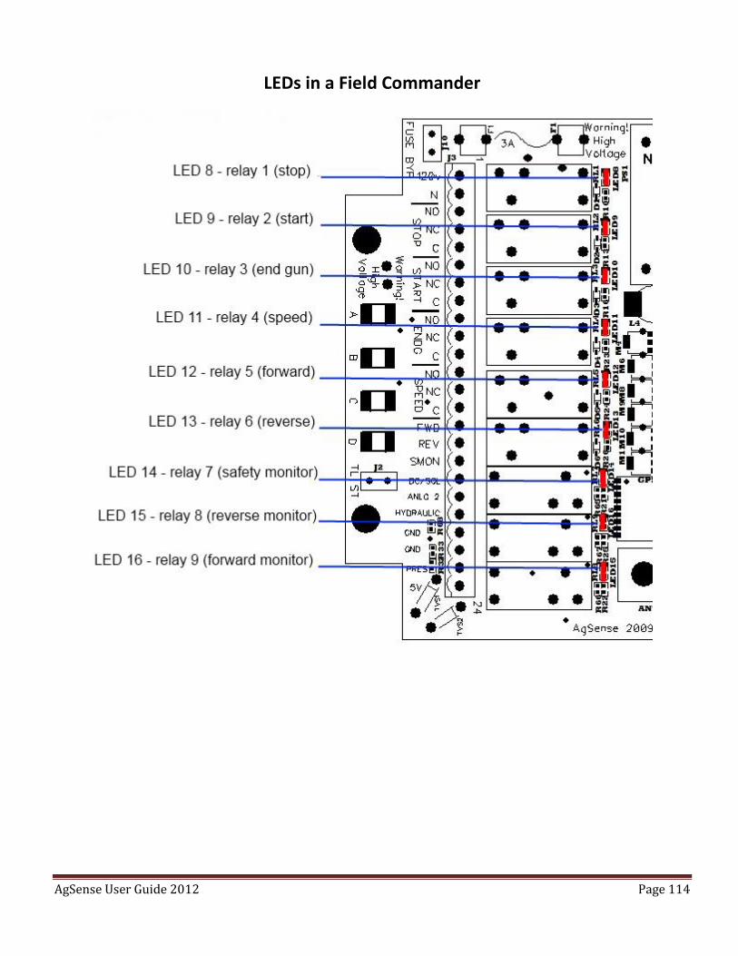
AgSense User Guide 2012 Page 114
LEDs in a Field Commander
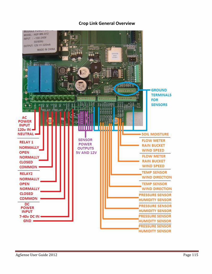
AgSense User Guide 2012 Page 115
Crop Link General Overview