Embed Size (px)
Citation preview

AssemblyOperationMaintenanceRepair Parts
CAUTION:Read Rules forSafe Operation
and InstructionsCarefully
OWNERSMANUAL
25 GALLON "PRO"TOW SPRAYER
Model No.45-02931
PRINTED IN USA FORM NO. 48303 (REV. 8/03)
Agri-Fab¨
the fastest way to purchase parts www.speedepart.com
2
RULES FOR SAFE OPERATION
Any power equipment can cause injury if operated improperly or if the user does not understand how to operatethe equipment. Exercise caution at all times when operating equipment.
1. Read this owners manual carefully before attempting to assemble or operate this sprayer.2. Read your vehicle owners manual for operating and safety rules before using this equipment.3. Never allow children to operate this sprayer, and do not allow adults to operate without proper instructions.4. Do not allow anyone to ride on or sit on this sprayer. Do not allow passengers on the towing vehicle.5. Keep the area of operation clear of all persons, particularly small children. Also keep area clear of pets.6. Read the chemical label carefully for instructions and caution notes on handling and mixing of chemicals.7. Wear eye and hand protection and wear protective clothing when handling and applying lawn chemicals.8. Do not spray on windy days.9. Attachment of this sprayer may affect your tractor's braking and stability. Be aware of your tractor's capabilities.
Refer to the safety rules in the vehicle owner's manual concerning safe operation on slopes. Be aware ofchanging conditions on slopes. STAY OFF OF STEEP SLOPES.
10. Operate at reduced speed on rough terrain, along ditches and on hillsides to prevent loss of control.11. Follow maintenance and lubrication instructions as outlined in this manual.
LOOK FOR THIS SYMBOL TO POINT OUTIMPORTANT SAFETY PRECAUTIONS. ITMEANS -- ATTENTION! BECOME ALERT! YOURSAFETY IS INVOLVED.
CARTON CONTENTSLOOSE PARTS IN CARTON
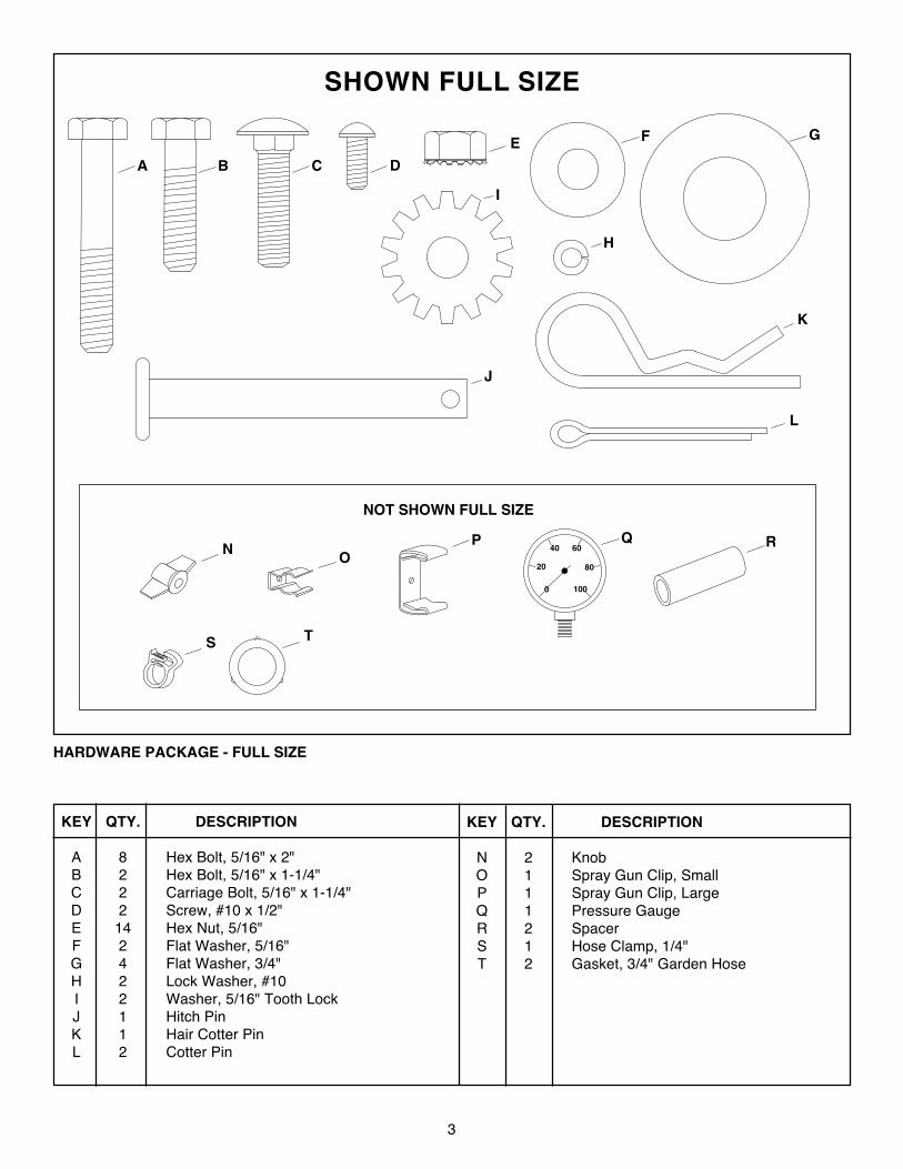
Your sprayer carton contains parts as shown in figure 1. The hardware package contains parts as shown in figure2. Identify all parts and layout as shown in figures 1 and 2.
1. Lid2. Tank3. Return/Bypass Hose (may be assembled to tank)4. Boom Assembly5. Boom Mount Bracket
6. Spray Gun Assembly7. Axle8. Hitch Arms (2)9. Hitch Brackets (2)10. Wheels (2)
13
6
10
9
4
7
5
2
8
3
SHOWN FULL SIZE
HARDWARE PACKAGE - FULL SIZE
OP
20
40 60
80
1000
NOT SHOWN FULL SIZE
Q R
TS
N
A
G
I
J
K
B C D
FE
H
L
KEY QTY. DESCRIPTION
A 8 Hex Bolt, 5/16" x 2"B 2 Hex Bolt, 5/16" x 1-1/4"C 2 Carriage Bolt, 5/16" x 1-1/4"D 2 Screw, #10 x 1/2"E 14 Hex Nut, 5/16"F 2 Flat Washer, 5/16"G 4 Flat Washer, 3/4"H 2 Lock Washer, #10I 2 Washer, 5/16" Tooth LockJ 1 Hitch PinK 1 Hair Cotter PinL 2 Cotter Pin
KEY QTY. DESCRIPTION
N 2 KnobO 1 Spray Gun Clip, SmallP 1 Spray Gun Clip, LargeQ 1 Pressure GaugeR 2 SpacerS 1 Hose Clamp, 1/4"T 2 Gasket, 3/4" Garden Hose
4
ASSEMBLY INSTRUCTIONS
FIGURE 2
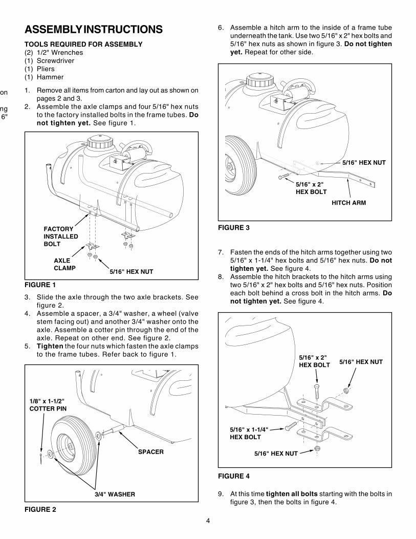
6. Assemble a hitch arm to the inside of a frame tubeunderneath the tank. Use two 5/16" x 2" hex bolts and5/16" hex nuts as shown in figure 3. Do not tightenyet. Repeat for other side.
TOOLS REQUIRED FOR ASSEMBLY(2) 1/2" Wrenches(1) Screwdriver(1) Pliers(1) Hammer
FIGURE 1
1. Remove all items from carton and lay out as shown onpages 2 and 3.
2. Assemble the axle clamps and four 5/16" hex nutsto the factory installed bolts in the frame tubes. Donot tighten yet. See figure 1.
FIGURE 3
7. Fasten the ends of the hitch arms together using two5/16" x 1-1/4" hex bolts and 5/16" hex nuts. Do nottighten yet. See figure 4.
8. Assemble the hitch brackets to the hitch arms usingtwo 5/16" x 2" hex bolts and 5/16" hex nuts. Positioneach bolt behind a cross bolt in the hitch arms. Donot tighten yet. See figure 4.
FIGURE 4
on
ng6"
3/4" WASHER
SPACER
1/8" x 1-1/2"COTTER PIN
3. Slide the axle through the two axle brackets. Seefigure 2.
4. Assemble a spacer, a 3/4" washer, a wheel (valvestem facing out) and another 3/4" washer onto theaxle. Assemble a cotter pin through the end of theaxle. Repeat on other end. See figure 2.
5. Tighten the four nuts which fasten the axle clampsto the frame tubes. Refer back to figure 1. 5/16" x 2"
HEX BOLT
5/16" HEX NUT
5/16" x 1-1/4"HEX BOLT
5/16" HEX NUT
9. At this time tighten all bolts starting with the bolts infigure 3, then the bolts in figure 4.
FACTORYINSTALLEDBOLT
AXLECLAMP 5/16" HEX NUT
5/16" x 2"HEX BOLT
5/16" HEX NUT
HITCH ARM
5
FIGURE 7
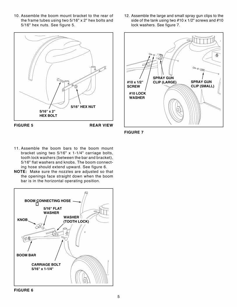
10. Assemble the boom mount bracket to the rear ofthe frame tubes using two 5/16" x 2" hex bolts and5/16" hex nuts. See figure 5.
FIGURE 5 REAR VIEW
11. Assemble the boom bars to the boom mountbracket using two 5/16" x 1-1/4" carriage bolts,tooth lock washers (between the bar and bracket),5/16" flat washers and knobs. The boom connect-ing hose should extend upward. See figure 6.
NOTE: Make sure the nozzles are adjusted so thatthe openings face straight down when the boombar is in the horizontal operating position.
FIGURE 6
5/16" HEX NUT5/16" x 2"HEX BOLT
CARRIAGE BOLT5/16" x 1-1/4"
KNOB
5/16" FLATWASHER
WASHER(TOOTH LOCK)
BOOM BAR
�BOOM CONNECTING HOSE
SPRAY GUNCLIP (LARGE) SPRAY GUN
CLIP (SMALL)#10 x 1/2"SCREW
#10 LOCKWASHER
12. Assemble the large and small spray gun clips to theside of the tank using two #10 x 1/2" screws and #10lock washers. See figure 7.
6
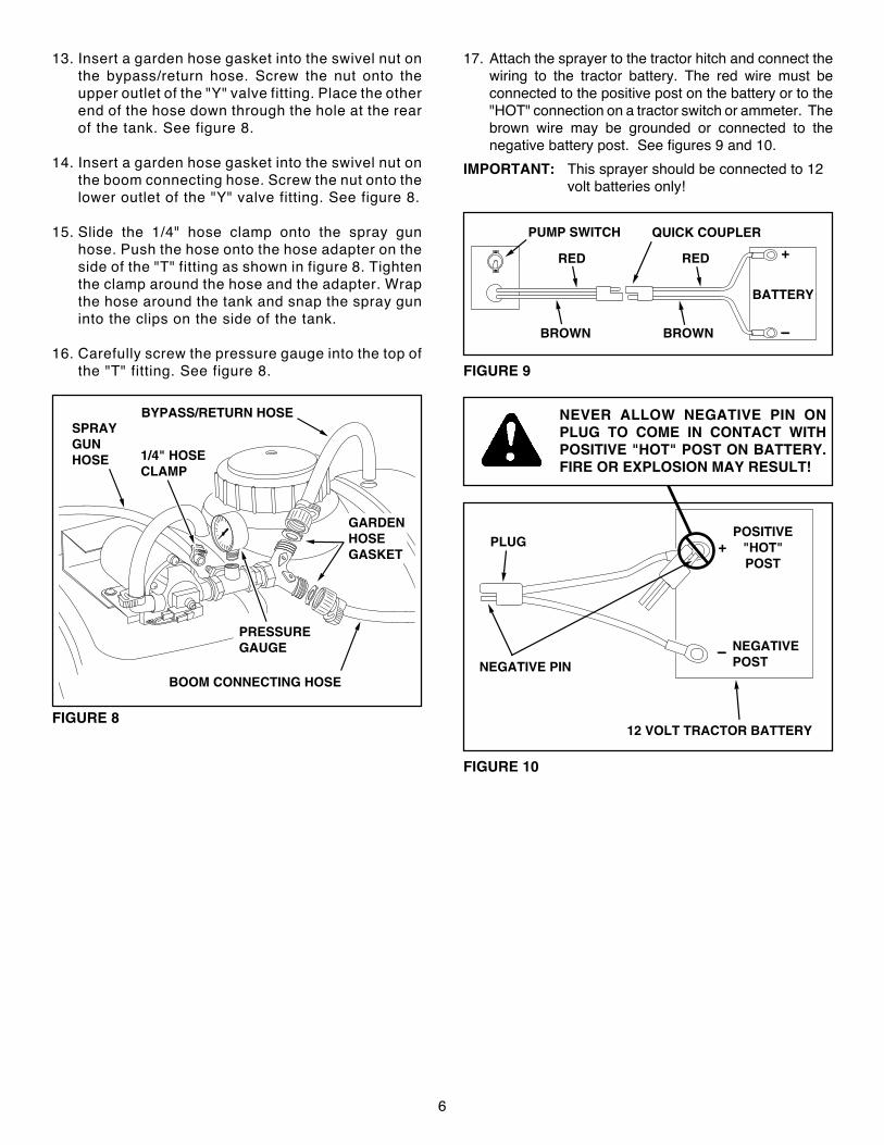
17. Attach the sprayer to the tractor hitch and connect thewiring to the tractor battery. The red wire must beconnected to the positive post on the battery or to the"HOT" connection on a tractor switch or ammeter. Thebrown wire may be grounded or connected to thenegative battery post. See figures 9 and 10.
IMPORTANT: This sprayer should be connected to 12volt batteries only!
13. Insert a garden hose gasket into the swivel nut onthe bypass/return hose. Screw the nut onto theupper outlet of the "Y" valve fitting. Place the otherend of the hose down through the hole at the rearof the tank. See figure 8.
14. Insert a garden hose gasket into the swivel nut onthe boom connecting hose. Screw the nut onto thelower outlet of the "Y" valve fitting. See figure 8.
15. Slide the 1/4" hose clamp onto the spray gunhose. Push the hose onto the hose adapter on theside of the "T" fitting as shown in figure 8. Tightenthe clamp around the hose and the adapter. Wrapthe hose around the tank and snap the spray guninto the clips on the side of the tank.
16. Carefully screw the pressure gauge into the top ofthe "T" fitting. See figure 8.
FIGURE 8
NEVER ALLOW NEGATIVE PIN ONPLUG TO COME IN CONTACT WITHPOSITIVE "HOT" POST ON BATTERY.FIRE OR EXPLOSION MAY RESULT!
FIGURE 10
FIGURE 9
BOOM CONNECTING HOSE
SPRAYGUNHOSE
PRESSUREGAUGE
1/4" HOSECLAMP
BYPASS/RETURN HOSE
GARDENHOSEGASKET
PLUG
NEGATIVE PIN
12 VOLT TRACTOR BATTERY
POSITIVE"HOT"POST
+
NEGATIVEPOST
BROWN
PUMP SWITCH
RED
QUICK COUPLER
BATTERY
+RED
BROWN
7
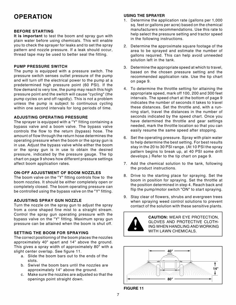
OPERATION USING THE SPRAYER1. Determine the application rate (gallons per 1,000
sq. feet or gallons per acre) based on the chemicalmanufacturers recommendations. Use this rate tohelp select the pressure setting and tractor speedin the following instructions.
2. Determine the approximate square footage of thearea to be sprayed and estimate the number ofgallons required. This can help avoid unneededsolution left in the tank.
3. Determine the appropriate speed at which to travel,based on the chosen pressure setting and therecommended application rate. Use the tip charton page 9.
4. To determine the throttle setting for attaining theappropriate speed, mark off 100, 200 and 300 feetintervals. The speed chart at the bottom of page 9indicates the number of seconds it takes to travelthese distances. Set the throttle and, with a run-ning start, travel the distances in the number ofseconds indicated by the speed chart. Once youhave determined the throttle and gear settingsneeded, mark the throttle location so that you caneasily resume the same speed after stopping.
6. Set the operating pressure. Spray with plain waterto help determine the best setting. For best resultsstay in the 20 to 30 PSI range. (At 10 PSI the spraypattern begins to break up, at 40 PSI some driftdevelops.) Refer to the tip chart on page 9.
7. Add the chemical solution to the tank, followingthe product instructions.
8. Drive to the starting place for spraying. Set theboom in position for spraying. Set the throttle atthe position determined in step 4. Reach back andflip the pump/motor switch "ON" to start spraying.
9. Stay clear of flowers, shrubs and evergreen treeswhen spraying weed control solutions to preventcontact of the solution with these sensitive plants.
BEFORE STARTINGIt is important to test the boom and spray gun withplain water before using chemicals. This will enableyou to check the sprayer for leaks and to set the spraypattern and nozzle pressure. If a leak should occur,thread tape may be used to better seal the fitting.
PUMP PRESSURE SWITCHThe pump is equipped with a pressure switch. Thepressure switch senses outlet pressure of the pumpand will turn off the electrical power to the pump at apredetermined high pressure point (60 PSI). If theflow demand is very low, the pump may reach this highpressure point and the switch will cause "cycling" (thepump cycles on and off rapidly). This is not a problemunless the pump is subject to continuous cyclingwithin one second intervals for long periods of time.
ADJUSTING OPERATING PRESSUREThe sprayer is equipped with a "Y" fitting containing abypass valve and a boom valve. The bypass valvecontrols the flow to the return (bypass) hose. Theamount of flow through the return hose determines theoperating pressure when the boom or the spray gun isin use. Adjust the bypass valve while either the boomor the spray gun is in use to obtain the desiredpressure, indicated by the pressure gauge. The tipchart on page 9 shows how different pressure settingsaffect boom application rates.
ON-OFF ADJUSTMENT OF BOOM NOZZLESThe boom valve on the "Y" fitting controls flow to theboom nozzles. It should be either completely open orcompletely closed. The boom operating pressure canbe controlled using the bypass valve on the "Y" fitting.
ADJUSTING SPRAY GUN NOZZLETurn the nozzle on the spray gun to adjust the sprayfrom a cone shaped fine mist to a straight stream.Control the spray gun operating pressure with thebypass valve on the "Y" fitting. Maximum spray gunpressure can be attained when the boom is shut off.
SETTING THE BOOM FOR SPRAYINGThe correct positioning of the boom places the nozzlesapproximately 40" apart and 14" above the ground.This gives a spray width of approximately 80" with aslight center overlap. See figure 11.
a. Slide the boom bars out to the ends of theslots.
b. Swivel the boom bars until the nozzles areapproximately 14" above the ground.
c. Make sure the nozzles are adjusted so that theopenings point straight down.
CAUTION: WEAR EYE PROTECTION,GLOVES AND PROTECTIVE CLOTH-ING WHEN HANDLING AND WORKINGWITH LAWN CHEMICALS.
FIGURE 11
80"
40"
14"
8
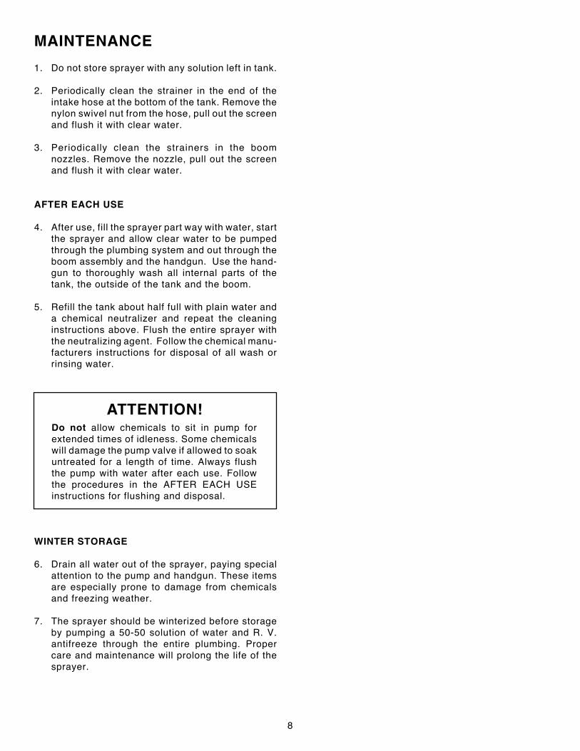
MAINTENANCE
1. Do not store sprayer with any solution left in tank.
2. Periodically clean the strainer in the end of theintake hose at the bottom of the tank. Remove thenylon swivel nut from the hose, pull out the screenand flush it with clear water.
3. Periodically clean the strainers in the boomnozzles. Remove the nozzle, pull out the screenand flush it with clear water.
AFTER EACH USE
4. After use, fill the sprayer part way with water, startthe sprayer and allow clear water to be pumpedthrough the plumbing system and out through theboom assembly and the handgun. Use the hand-gun to thoroughly wash all internal parts of thetank, the outside of the tank and the boom.
5. Refill the tank about half full with plain water anda chemical neutralizer and repeat the cleaninginstructions above. Flush the entire sprayer withthe neutralizing agent. Follow the chemical manu-facturers instructions for disposal of all wash orrinsing water.
ATTENTION!Do not allow chemicals to sit in pump forextended times of idleness. Some chemicalswill damage the pump valve if allowed to soakuntreated for a length of time. Always flushthe pump with water after each use. Followthe procedures in the AFTER EACH USEinstructions for flushing and disposal.
WINTER STORAGE
6. Drain all water out of the sprayer, paying specialattention to the pump and handgun. These itemsare especially prone to damage from chemicalsand freezing weather.
7. The sprayer should be winterized before storageby pumping a 50-50 solution of water and R. V.antifreeze through the entire plumbing. Propercare and maintenance will prolong the life of thesprayer.
9
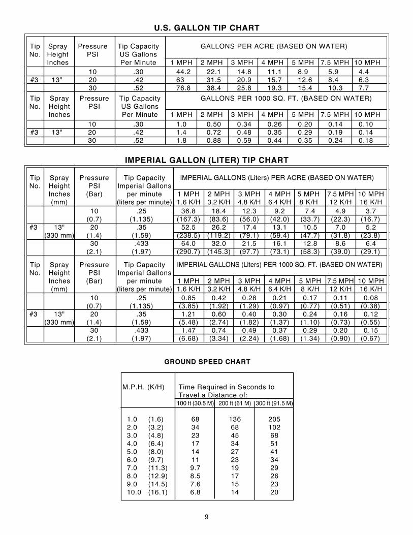
10 .25 36.8 18.4 12.3 9.2 7.4 4.9 3.7(0.7) (1.135) (167.3) (83.6) (56.0) (42.0) (33.7) (22.3) (16.7)
#3 13" 20 .35 52.5 26.2 17.4 13.1 10.5 7.0 5.2(330 mm) (1.4) (1.59) (238.5) (119.2) (79.1) (59.4) (47.7) (31.8) (23.8)
30 .433 64.0 32.0 21.5 16.1 12.8 8.6 6.4(2.1) (1.97) (290.7) (145.3) (97.7) (73.1) (58.3) (39.0) (29.1)
Tip Spray Pressure Tip CapacityNo. Height PSI Imperial Gallons
Inches (Bar) per minute 1 MPH 2 MPH 3 MPH 4 MPH 5 MPH 7.5 MPH 10 MPH(mm) (liters per minute) 1.6 K/H 3.2 K/H 4.8 K/H 6.4 K/H 8 K/H 12 K/H 16 K/H
IMPERIAL GALLONS (Liters) PER 1000 SQ. FT. (BASED ON WATER)
IMPERIAL GALLONS (Liters) PER ACRE (BASED ON WATER)
10 .30 44.2 22.1 14.8 11.1 8.9 5.9 4.4#3 13" 20 .42 63 31.5 20.9 15.7 12.6 8.4 6.3
30 .52 76.8 38.4 25.8 19.3 15.4 10.3 7.7
Tip Spray Pressure Tip Capacity GALLONS PER 1000 SQ. FT. (BASED ON WATER)No. Height PSI US Gallons
Inches Per Minute 1 MPH 2 MPH 3 MPH 4 MPH 5 MPH 7.5 MPH 10 MPH10 .30 1.0 0.50 0.34 0.26 0.20 0.14 0.10
#3 13" 20 .42 1.4 0.72 0.48 0.35 0.29 0.19 0.1430 .52 1.8 0.88 0.59 0.44 0.35 0.24 0.18
IMPERIAL GALLON (LITER) TIP CHART
U.S. GALLON TIP CHART
10 .25 0.85 0.42 0.28 0.21 0.17 0.11 0.08(0.7) (1.135) (3.85) (1.92) (1.29) (0.97) (0.77) (0.51) (0.38)
#3 13" 20 .35 1.21 0.60 0.40 0.30 0.24 0.16 0.12(330 mm) (1.4) (1.59) (5.48) (2.74) (1.82) (1.37) (1.10) (0.73) (0.55)
30 .433 1.47 0.74 0.49 0.37 0.29 0.20 0.15(2.1) (1.97) (6.68) (3.34) (2.24) (1.68) (1.34) (0.90) (0.67)
Tip Spray Pressure Tip Capacity GALLONS PER ACRE (BASED ON WATER)No. Height PSI US Gallons
Inches Per Minute 1 MPH 2 MPH 3 MPH 4 MPH 5 MPH 7.5 MPH 10 MPH
Tip Spray Pressure Tip CapacityNo. Height PSI Imperial Gallons
Inches (Bar) per minute 1 MPH 2 MPH 3 MPH 4 MPH 5 MPH 7.5 MPH 10 MPH(mm) (liters per minute) 1.6 K/H 3.2 K/H 4.8 K/H 6.4 K/H 8 K/H 12 K/H 16 K/H
M.P.H. (K/H) Time Required in Seconds toTravel a Distance of:
100 ft (30.5 M) 200 ft (61 M) 300 ft (91.5 M)
1.0 (1.6) 68 136 2052.0 (3.2) 34 68 1023.0 (4.8) 23 45 684.0 (6.4) 17 34 515.0 (8.0) 14 27 416.0 (9.7) 11 23 347.0 (11.3) 9.7 19 298.0 (12.9) 8.5 17 269.0 (14.5) 7.6 15 2310.0 (16.1) 6.8 14 20
GROUND SPEED CHART
10
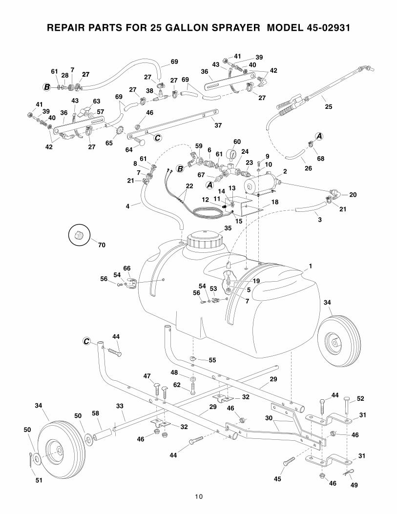
REPAIR PARTS FOR 25 GALLON SPRAYER MODEL 45-02931
34
31
44
46 49
5233 29
30
31
48
55
62
C
46
29
46
44
34
51
50
50 58
45
25
68
26
37
27
43
36
42
3941
4057
69
2727
3827
3643
42
27
394140
6927
63
6465
B
C
44
46
35
1
A
7
596
61
60
24
232
20
3
8
21
4
9 10
61
B
22
181112
1314
15
67
519
756
54 53
66
56 54
21
2861 7
27
B
69
32
46
32
47
A
70
11
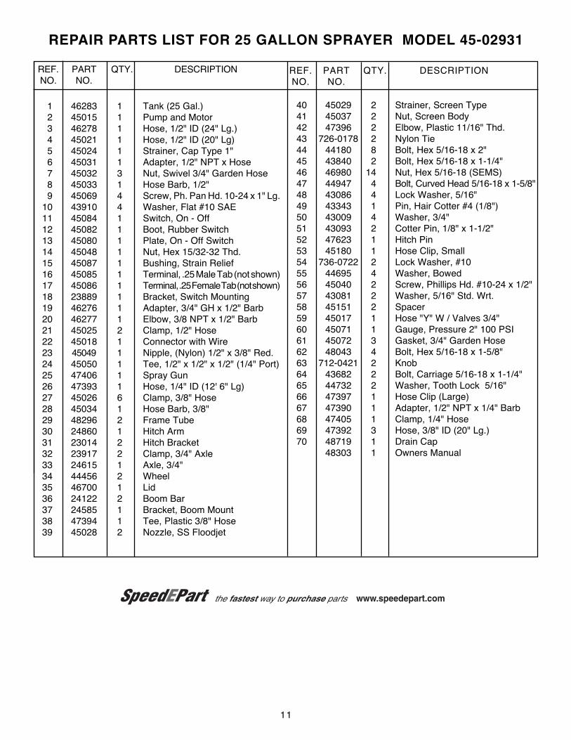
REPAIR PARTS LIST FOR 25 GALLON SPRAYER MODEL 45-02931
REF. PART QTY. DESCRIPTIONNO. NO.
40 45029 2 Strainer, Screen Type41 45037 2 Nut, Screen Body42 47396 2 Elbow, Plastic 11/16" Thd.43 726-0178 2 Nylon Tie44 44180 8 Bolt, Hex 5/16-18 x 2"45 43840 2 Bolt, Hex 5/16-18 x 1-1/4"46 46980 14 Nut, Hex 5/16-18 (SEMS)47 44947 4 Bolt, Curved Head 5/16-18 x 1-5/8"48 43086 4 Lock Washer, 5/16"49 43343 1 Pin, Hair Cotter #4 (1/8")50 43009 4 Washer, 3/4"51 43093 2 Cotter Pin, 1/8" x 1-1/2"52 47623 1 Hitch Pin53 45180 1 Hose Clip, Small54 736-0722 2 Lock Washer, #1055 44695 4 Washer, Bowed56 45040 2 Screw, Phillips Hd. #10-24 x 1/2"57 43081 2 Washer, 5/16" Std. Wrt.58 45151 2 Spacer59 45017 1 Hose "Y" W / Valves 3/4"60 45071 1 Gauge, Pressure 2" 100 PSI61 45072 3 Gasket, 3/4" Garden Hose62 48043 4 Bolt, Hex 5/16-18 x 1-5/8"63 712-0421 2 Knob64 43682 2 Bolt, Carriage 5/16-18 x 1-1/4"65 44732 2 Washer, Tooth Lock 5/16"66 47397 1 Hose Clip (Large)67 47390 1 Adapter, 1/2" NPT x 1/4" Barb68 47405 1 Clamp, 1/4" Hose69 47392 3 Hose, 3/8" ID (20" Lg.)70 48719 1 Drain Cap
48303 1 Owners Manual
REF. PART QTY. DESCRIPTIONNO. NO.
1 46283 1 Tank (25 Gal.)2 45015 1 Pump and Motor3 46278 1 Hose, 1/2" ID (24" Lg.)4 45021 1 Hose, 1/2" ID (20" Lg)5 45024 1 Strainer, Cap Type 1"6 45031 1 Adapter, 1/2" NPT x Hose7 45032 3 Nut, Swivel 3/4" Garden Hose8 45033 1 Hose Barb, 1/2"9 45069 4 Screw, Ph. Pan Hd. 10-24 x 1" Lg.
10 43910 4 Washer, Flat #10 SAE11 45084 1 Switch, On - Off12 45082 1 Boot, Rubber Switch13 45080 1 Plate, On - Off Switch14 45048 1 Nut, Hex 15/32-32 Thd.15 45087 1 Bushing, Strain Relief16 45085 1 Terminal, .25 Male Tab (not shown)17 45086 1 Terminal, .25 Female Tab (not shown)18 23889 1 Bracket, Switch Mounting19 46276 1 Adapter, 3/4" GH x 1/2" Barb20 46277 1 Elbow, 3/8 NPT x 1/2" Barb21 45025 2 Clamp, 1/2" Hose22 45018 1 Connector with Wire23 45049 1 Nipple, (Nylon) 1/2" x 3/8" Red.24 45050 1 Tee, 1/2" x 1/2" x 1/2" (1/4" Port)25 47406 1 Spray Gun26 47393 1 Hose, 1/4" ID (12' 6" Lg)27 45026 6 Clamp, 3/8" Hose28 45034 1 Hose Barb, 3/8"29 48296 2 Frame Tube30 24860 1 Hitch Arm31 23014 2 Hitch Bracket32 23917 2 Clamp, 3/4" Axle33 24615 1 Axle, 3/4"34 44456 2 Wheel35 46700 1 Lid36 24122 2 Boom Bar37 24585 1 Bracket, Boom Mount38 47394 1 Tee, Plastic 3/8" Hose39 45028 2 Nozzle, SS Floodjet
the fastest way to purchase parts www.speedepart.com

REPAIR PARTSAgri-Fab, Inc.
303 West RaymondSullivan, IL. 61951
217-728-8388www.agri-fab.com
the fastest way to purchase parts www.speedepart.com