Embed Size (px)
Citation preview

Page 1 of 15
Celotex Limited Lady Lane Industrial Estate Hadleigh Ipswich Suffolk IP7 6BA
Tel: 01473 822093 Fax: 01473 820880 Agrément Certificate e-mail: [email protected] 12/4926 website: www.celotex.co.uk Product Sheet 1
CELOTEX INSULATION CELOTEX PIR PLASTERBOARD THERMAL LAMINATES
This Agrément Certificate Product Sheet(1) relates to Celotex PIR Plasterboard Thermal Laminates, comprising rigid polyisocyanurate (PIR) foam boards bonded to plasterboard, for use as an insulating dry lining system for internal wall applications in existing domestic and non-domestic buildings.
(1) Hereinafter referred to as ‘Certificate’.
CERTIFICATION INCLUDES:
• factors relating to compliance with Building Regulations where applicable
• factors relating to additional non-regulatory information where applicable
• independently verified technical specification • assessment criteria and technical investigations • design considerations • installation guidance • regular surveillance of production • formal three-yearly review.
KEY FACTORS ASSESSED
Thermal performance — the insulation component of the systems has a declared thermal conductivity* (λD) of 0.022 W·m–1·K–1 (Celotex PL4000) and 0.021 W·m–1·K–1 (Celotex GD5000 and Celotex GS5000) (see se tion 6).
Condensation risk — the systems can limit the risk of surface condensation and the risk of interstitial condensation should be assessed for each case (see section 7).
Behaviour in relation to fire — the boards have a fire classification* of Euroclass B-s1, d0 to BS EN 13501-1 : 2007 (see section 8).
Durability — under normal conditions, the boards are rot-proof, dimensionally stable and durable and will remain effective for the life of the building in which they are installed (see section 14).
The BBA has awarded this Certificate to the company named above for the systems described herein. These systems have been assessed by the BBA as being fit for their intended use provided they are installed, used and maintained as set out in this Certificate.
On behalf of the British Board of Agrement
Date of Fourth issue: 12 October 2015
Originally certificated on 16 August 2012
John Albon – Head of Approvals Construction Products
Claire Curtis-Thomas Chief Executive
The BBA is a UKAS accredited certification body – Number 113. The schedule of the current scope of accreditation for product certification is available in pdf format via the UKAS link on the BBA website at www.bbacerts.co.uk
British Board of Agrément Bucknalls Lane Watford Herts WD25 9BA
©2015
tel: 01923 665300 fax: 01923 665301
[email protected] www.bbacerts.co.uk

Page 2 of 15
Regulations In the opinion of the BBA, Celotex PIR Plasterboard Thermal Laminates, if installed, used and maintained in accordance with this Certificate, can satisfy or contribute to satisfying the relevant requirements of the following Building Regulations (the presence of a UK map indicates that the subject is related to the Building Regulations in the region or regions of the UK depicted):
The Building Regulations 2010 (England and Wales) (as amended)
Requirement: B2(1) Internal fire spread (linings) Comment: The systems are unrestricted under this Requirement. See section 8.1 of this Certificate. Requirement: C2(c) Resistance to moisture Comment: The systems can contribute to satisfying this Requirement. See sections 7.1 and 7.6 of
this Certificate. Requirement: L1(a)(i) Conservation of fuel and power Comment: The systems can contribute to satisfying this Requirement. See section 6 of this
Certificate. Regulation: 7 Materials and workmanship Comment: The systems are acceptable. See section 14 and the Installation part of this Certificate.
The Building (Scotland) Regulations 2004 (as amended)
Regulation: 8(1) Durability, workmanship and fitness of materials Comment: The systems can contribute to satisfying this Regulation. See section 14 and the
Installation part of this Certificate. Regulation: 9 Building standards applicable to construction Standard: 2.5 Internal linings Comment: The systems are unrestricted by this Standard, with reference to clause 2.5.1(1)(2). See
section 8.1 of this Certificate. Standard: 3.15 Condensation Comment: The systems can contribute to satisfying this Standard, with reference to clauses
3.15.1(1)(2), 3.15.4(1)(2) and 3.15.5(1)(2). See sections 7.1 and 7.7 of this Certificate. Standard: 6.1(b) Carbon dioxide emissions Standard: 6.2 Building insulation envelope Comment: The systems can contribute to satisfying these Standards, with reference to clauses or
parts of 6.1.6(1), 6.2.1(1)(2), 6.2.3(1), 6.2.4(2), 6.2.5(2), 6.2.9(1), 6.2.11(1) and 6.2.12(2). See section 6 of this Certificate.
Standard: 7.1(a)(b) Statement of sustainability Comment: The systems can contribute to satisfying the relevant requirements of Regulation 9,
Standards 1 to 6, and, therefore, will contribute to a construction meeting a bronze level of sustainability as defined in this Standard. See section 6.1 of this Certificate.
Regulation: 12 Building standards applicable to conversions Comment: All comments given for the systems under Regulation 9, Standards 1 to 6, also apply to
this Regulation, with reference to clause 0.12.1(1)(2) and Schedule 6(1)(2). (1) Technical Handbook (Domestic).
(2) Technical Handbook (Non-Domestic).

Page 3 of 15
The Building Regulations (Northern Ireland) 2012 (as amended)
Regulation: 23 Fitness of materials and workmanship Comment: The systems are acceptable. See section 14 and the Installation part of this Certificate. Regulation: 29 Condensation Comment: The systems can contribute to satisfying this Regulation. See section 7.1 of this
Certificate. Regulation: 34 Internal fire spread — Linings Comment: The systems are unrestricted by this Regulation. See section 8.1 of this Certificate. Regulation: 39(a)(i) Conservation measures Comment: The systems are acceptable. See section 6 of this Certificate.
Construction (Design and Management) Regulations 2015 Construction (Design and Management) Regulations (Northern Ireland) 2007 Information in this Certificate may assist the client, Principal Designer/CDM co-ordinator, designer and contractors to address their obligations under these Regulations. See section: 3 Delivery and site handling (3.3) of this Certificate.
Additional Information
NHBC Standards 2014 NHBC accepts the use of Celotex PIR Plasterboard Thermal Laminates, provided they are installed, used and maintained in accordance with this Certificate, in relation to NHBC Standards, Chapter 8.2 Wall and ceiling finishes.
CE marking
The Certificate holder has taken the responsibility of CE marking the products in accordance with harmonised European Standard BS EN 13950 : 2005. An asterisk (*) appearing in this Certificate indicates that data shown is given in the manufacturer’s Declaration of Performance.
Technical Specification
1 Description 1.1 Celotex PIR Plasterboard Thermal Laminates consist of PIR insulation, bonded to plasterboard as listed in Table 1. Celotex PL4000 and Celotex GD5000 feature a bilaminate foil/kraft paper-facing allowing them to be installed either by direct bonding to the wall using plaster adhesive dabs, or by being mechanically fixed either directly to the wall or onto timber battens or metal furring systems. Celotex GS5000 features low emissivity foil-facings for mechanical fixing only, either directly to the wall or onto timber battens or metal furring systems (see the Installation part of this Certificate).

Page 4 of 15
Table 1 Product summary
Product Board size (mm)
Plasterboard thickness(1)
(mm)
PlR insulation thickness
(mm)
Board facings Fixing method
Celotex PL4000
1200 x 2400
12.5
15 to 80
Bilaminate foil/ kraft paper-facing
Direct bonding or mechanical
fixing
Celotex GD5000 1200 x 2400 12.5 25 to 80 Bilaminate foil/
kraft paper-facing
Direct bonding or mechanical
fixing
Celotex GS5000 1200 x 2400 12.5 25 to 80 Aluminium foil-
facing (unprinted) Mechanical fixing only
(1) 12.5 mm is the standard plasterboard thickness supplied laminated to the insulation; however, 9.5 mm thickness plasterboard can be supplied upon request. The Certificate holder should be contacted for further details.
1.2 Ancillary items for use with the systems, which are outside the scope of this Certificate: ● gypsum-based dry lining adhesive compound (plaster dabs) to BS EN 14496 : 2005 ● metal component furring systems to BS EN 14195 : 2005 ● mechanical fasteners including dry wall screws, plasterboard nails and nailable plugs to BS EN 14566 : 2008 ● metal edge and corner beads to BS EN 14353 : 2007 ● jointing materials including scrim tape and jointing compound to BS EN 13963 : 2005 ● softwood timber battens.
2 Manufacture 2.1 The insulation component of Celotex PL4000, Celotex GD5000 and Celotex GS5000 is manufactured by a lamination process whereby the board is formed between either a bilaminate foil/kraft paper-facing or aluminium foil-facing that is adhered in a continuous laminator, where the ‘adhesive’ is a mixture of two primary chemicals, polyol and MDI. An added blowing agent causes the adhesive to expand into foam that sets, which is then cut to its finished board size. The board is bonded to plasterboard. 2.2 As part of the assessment and ongoing surveillance of product quality, the BBA has:
agreed with the manufacturer the quality control procedures and product testing to be undertaken
assessed and agreed the quality control operated over batches of incoming materials
monitored the production process and verified that it is in accordance with the documented process
evaluated the process for management of nonconformities
checked that equipment has been properly tested and calibrated
undertaken to carry out the above measures on a regular basis through a surveillance process, to verify that the specifications and quality control being operated by the manufacturer are being maintained.
2.3 The management system of Celotex Limited has been assessed and registered as meeting the requirements of BS EN ISO 9001 : 2008 and BS EN ISO 14001 : 2004 by SGS UK Ltd (Certificates GB91/504 and GB11/83526).
3 Delivery and site handling 3.1 The boards are delivered to site in polythene wrapped packs. Each pack contains a label bearing the manufacturer’s name, board dimensions and the BBA logo incorporating the number of this Certificate. 3.2 The boards must be protected from prolonged exposure to sunlight and moisture and should be stored inside, under cover and protected with opaque polythene sheeting. The boards should be stacked flat and raised above ground level, and not in contact with ground moisture. 3.3 Care must be taken when handling the boards to avoid crushing the edges or corners, and to avoid contact with solvents or bitumen products. The boards must not be exposed to open flame or other ignition sources.

Page 5 of 15
Assessment and Technical Investigations The following is a summary of the assessment and technical investigations carried out on Celotex PIR Plasterboard Thermal Laminates.
Design Considerations
4 Use 4.1 Celotex PIR Plasterboard Thermal Laminates are satisfactory for use as an insulating dry lining system for solid or cavity masonry walls of existing domestic and non-domestic buildings. The boards should be installed in accordance with the Certificate holder’s instructions. 4.2 The boards may be installed on masonry construction including clay and calcium silicate bricks, concrete blocks, and natural and reconstituted stone blocks. 4.3 The systems are not intended to offer resistance to rain penetration, therefore walls must be already rain resistant and show no signs of water ingress, rain penetration or damp from ground moisture. 4.4 Services which penetrate the dry lining, eg light switches and power outlets, should be kept to a minimum to limit damage to vapour checks. All perimeters of the board, around service penetrations, openings, junctions and around the perimeter of suspended timber floors must be sealed with a suitable sealant. 4.5 It is essential that proper care and attention is given to maintaining the integrity/continuity of the insulation and facings. 4.6 De-rating of any electrical cables in areas where the systems restrict the flow of air should be considered. 4.7 With installations that form a void of 20 mm or more (ie timber batten or metal furring systems), services can be incorporated behind the dry lining, making the chasing of the wall unnecessary. Where the services have a greater depth than the void, the wall should be chased rather than the insulation. 4.8 The installation of the systems require careful detailing around doors and windows to achieve a satisfactory surface for finishing. In addition, every attempt should be made to minimise the risk of thermal bridging at reveals and where heavy separating walls are attached to the external wall. Thinner boards should be selected from the Celotex PIR Plasterboard Thermal Laminates range to suit site-specific door and window reveal conditions. All work must be designed to accommodate the thickness of the dry lining, particularly at reveals, heads, sills and in relation to ceiling height. Where the dimensions of fixtures are critical (eg bathrooms), these should be checked before installation. 4.9 If present, mould or fungal growth should be treated prior to the application of the systems.
5 Practicability of installation The systems are designed to be installed by a competent general builder, or a contractor, experienced with these types of systems.
6 Thermal performance
6.1 Calculations of thermal transmittance (U value) of a specific construction using insulated dry lining should be carried out in accordance with BS EN ISO 6946 : 2007, BRE Report BR 443 : 2006 and BRE
Digest 465: 2002 , using the declared thermal conductivity* (λD value) for the insulation component as
shown in Table 2, a design value of 0.19 W·m–1·K–1 for the plasterboard, and aged emissivity (εD) values of 0.9 for the bilaminate foil/kraft paper-facings and 0.03 for the single-layer foil-facings respectively. The single-layer foil-facing has an unprinted face.
Page 6 of 15
Table 2 Thermal conductivities for the PIR insulation
Product Declared thermal conductivity* (λD) (W·m–1·K–1)
Celotex PL4000 0.022
Celotex GD5000 0.021
Celotex GS5000 0.021
6.2 The U value of a completed wall construction will depend on the insulation thickness, number and
type of fixings, the insulating value of the substrate masonry and its internal finish. Calculated U values for example constructions in accordance with the national Building Regulations are given in Table 3.
Table 3 Example U values — Solid brickwork wall(1)
Celotex PL4000, GD5000 and GS5000 Thickness of insulation(2) (mm), as dry lining
Target U value (W·m–2·K–1)
Direct bond (plaster dabs)(3)
Mechanical fixing direct to wall(4)
Mechanical fixing to timber battens(5)
GD5000 PL4000 GD5000 PL4000 GS5000
0.26 70 70 70 75 80
0.30 60 60 60 65 70 (1) 215 mm thick existing solid brickwork wall (0.77 W·m–1·K–1 thermal conductivity). (2) Thickness of insulation specified excludes plasterboard thickness of 12.5 mm. (3) Direct bonding with 15 mm plaster adhesive dabs (15 mm air cavity). Boards adhesively fixed in addition to 0.69 fully penetrating steel fixings
(50 W·m–1·K–1) per square metre with a cross-sectional area of 18.2 mm2 (minimum of two nailable fixings, at midpoint of the board, 25 mm from board edge).
(4) Mechanical fixing direct to wall using 4.16 fully penetrating stainless steel fixings (17 W·m–1·K–1) per square metre with a cross-sectional area of 9 mm2 (stainless steel fixings at 300 mm centres from the vertical and horizontal board edges, with a minimum of 12 fixings per board).
(5) Mechanical fixing to treated softwood timber battens, 22 mm batten cavity. Boards mechanically fixed with 10.35 fully penetrating steel fixings (50 W·m–1·K–1) per square metre with a cross-sectional area of 18.2 mm2 (47 mm wide timber battens at 600 mm centres maximum).
Junctions
6.3 Care must be taken in the overall design and construction of junctions with other elements and openings to minimise thermal bridges and air infiltration. Detailed guidance can be found in the documents supporting the national Building Regulations. An example of an acceptable junction detail is shown in Figure 1.

Page 7 of 15
Figure 1 Junction between the wall and the floor
7 Condensation risk
Interstitial condensation
7.1 Walls incorporating the systems will adequately limit the risk of interstitial condensation when they are designed and constructed in accordance with BS 5250 : 2011, Annexes D and G.
7.2 For condensation risk analysis, the water vapour transmission factors for each component given in Table 4 are to be used as separate layers.
Table 4 Water vapour transmission factors
Material Water vapour resistance (MN·s·g–1)
Water vapour resistivity (MN·s·g–1·m–1)
Plasterboard 10 —
PIR foam insulation — 300
Bilaminate foil/kraft paper-facing >70 —
Single-layer aluminium foil-facing >70 —
7.3 For each construction, a condensation risk analysis should be carried out in accordance with BS EN ISO 13788 : 2012 and BS 5250 : 2011 using the values given in Table 4. 7.4 To reduce the risk of condensation, insulation should be continued behind ancillary items fixed to the wall, such as sinks and cupboards. Such ancillary items should be fixed through the insulation to the underlying structural substrate (see section 12 of this Certificate). 7.5 Provided all joints between the systems are sealed in accordance with the Certificate holder’s instructions, they can offer a significant resistance to water vapour transmission. This can be conducted by application of either a skim coat or taping and filling of the tapered edges of the plasterboards.
Page 8 of 15
Surface condensation
7.6 Walls incorporating the systems will adequately limit the risk of surface condensation when the thermal transmittance (U value) does not exceed 0.7 W·m–2·K–1 at any point and the junctions with other elements are designed in accordance with the guidance referred to in section 6.3 of this Certificate.
7.7 Walls will adequately limit the risk of surface condensation when the thermal transmittance (U value) does not exceed 1.2 W·m–2·K–1 at any point. Guidance may be obtained from BS 5250 : 2011, Annex G and BRE Report BR 262 : 2002.
7.8 As with other types of insulation applied to the inside of a wall, there may be a risk of cold bridging from the floors or ceilings, particularly in concrete slab construction. It has been demonstrated that use of coving at the wall ceiling joint will significantly reduce this risk. 7.9 Dry lining has been used successfully in the rehabilitation of buildings suffering from surface condensation of walls where the dampness has been caused by the lack of thermal insulation.
8 Behaviour in relation to fire
8.1 The systems have been classified for fire* as Euroclass B-s1, d0 to BS EN 13501-1 : 2007 and are unrestricted with respect to surface spread of flame under the national Building Regulations.
8.2 When properly installed, the insulation will be contained between the wall and internal lining board until one is compromised. Therefore, the insulation will not contribute to the development of a fire or present a smoke or toxic hazard as the fire develops. 8.3 Any cavities formed by the systems (such as those formed between the thermal liner and the substrate wall) must have appropriate fire stopping in accordance with the relevant national Building Regulations: England and Wales — Approved Document B, Volumes 1 and 2 Scotland — Mandatory Standard 2.4, clause 2.4.2(1)(2) (1) Technical Handbook (Domestic). (2) Technical Handbook (Non-Domestic).
Northern Ireland — Technical Booklet E, paragraphs 4.36 to 4.42.
9 Proximity of flues and appliances When the systems are installed in close proximity to certain flue pipes and/or heat-producing appliances, the relevant provisions of the national Building Regulations should be met: England and Wales — Approved Document J Scotland — Mandatory Standard 3.19, clauses 3.19.1(1)(2) to 3.19.4(1)(2) (1) Technical Handbook (Domestic). (2) Technical Handbook (Non-Domestic).
Northern Ireland — Technical Booklet L, sections 1 to 5.
10 Materials in contact — wiring installations 10.1 Electrical cables likely to come into contact with the insulation component of the thermal liner are required to be protected by a suitable conduit or PVC-U trunking.

Page 9 of 15
10.2 As with any other forms of insulation, de-rating of electrical cables should be considered where the insulation restricts the air cooling of cables.
11 Infestation Use of the systems does not in itself promote infestation. The creation of voids within the structure, for example gaps between the wall lining and the systems, may provide habitation for insects or vermin in areas already infested. Care should be taken to ensure, wherever possible, that all voids are sealed, as any infestation may be difficult to eradicate. There is no food value in the materials used.
12 Wall-mounted fittings The recommendations of the Certificate holder must be followed. Any object fixed to the wall, other than lightweight items, eg framed pictures, should be fixed through the lining board into the wall behind, using recommended proprietary fixings.
13 Maintenance If the systems are damaged during use, they can be readily removed and replaced.
14 Durability
Provided the systems are fixed to satisfactory stable and durable backgrounds by an experienced contractor, they will have a life equal to the building in which they are installed. Under normal conditions of occupancy they are unlikely to suffer damage, but if damage does occur, repairs are easily carried out.
Installation
15 General 15.1 Celotex PIR Plasterboard Thermal Laminates are for use as an insulated dry lining system on internal walls. Celotex PL4000 and Celotex GD5000 feature bilaminate facings allowing them to be installed by either direct bonding to the wall using plaster adhesive dabs, or mechanically fixed either directly to the wall or onto timber battens or metal furring systems. Celotex GS5000 features low-emissivity foil-facings for mechanical fixing only, fixed either directly to the wall or onto timber battens or metal furring systems. Typical installation methods are shown in Figures 2 and 3.
Figure 2 Direct bonding to wall

Page 10 of 15
Figure 3 Mechanically fixed to timber battens or metal furrings
15.2 Prior to installation it is important to ensure the wall is sound, secure, free from contaminants and dry. If present, mould or fungal growth should be treated prior to the application of the systems. Wallpaper, gloss paint, skirting, picture rails and projecting window boards should be removed and made good as necessary. 15.3 All insulated dry lining installations require careful planning and setting out. The direct bonding method allows for variable flatness of the wall. In all instances, the background should be plumbed for alignment, making allowances for high spots on the masonry. Chalk lines are marked on the floor and ceiling to establish the new wall plane. Vertical guidelines should be marked on the wall. Fixing positions are determined by lining system type. 15.4 Installation should be in accordance with BS 8212 : 1995, good dry lining practice and the Certificate holder’s instructions. Before fixing the systems, sufficient time must be allowed for damp-proofing treatments, where applied, to dry out [see also BS 6576 : 2005 for dry lining in conjunction with a chemical damp-proof course (dpc) application]. 15.5 The systems can be cut using a fine-toothed saw, to fit around windows, doors, air bricks. It is essential that cut pieces completely fill the spaces for which they are intended and are adequately secured. 15.6 Vertical guidelines on the wall should be marked at 1200 mm centres to indicate the positioning of the boards. 15.7 The installation should start from an internal corner or a window or door reveal. 15.8 Regardless of method used, additional consideration should also be given for the fixing of such features as cupboards, radiators (see section 12 of this Certificate).
16 Procedure
Celotex PL4000 and Celotex GD5000 — Direct bonding using plaster adhesive dabs 16.1 A continuous bed of adhesive should be applied around the perimeter of the wall as well as around any services or other openings. This is especially important when considering the airtightness of the building. All conduits and piping should be installed prior to commencement of all works. The insulating backing of the laminates should not be removed to accommodate services. 16.2 Adhesive dabs should be applied in three rows with each dab approximately 75 mm by 250 mm in dimension. Intermediate dabs at ceiling level should be applied and individual dabs should not bridge boards. Typically, the adhesive dabs should cover at least 20% of the board area. 16.3 The board should be cut approximately 15 mm short of the floor to ceiling height and positioned with the bottom edge resting on packing strips. The boards are tapped into position with a straight-edge, and alignment checked with the chalk lines.

Page 11 of 15
16.4 Once positioned, the board should be lifted to the ceiling edge using a floor lifter and supported until the adhesive has set. Once set, a minimum of two nailable fixings should be applied at the mid-point of the board and approximately 25 mm from the board edge. Nailable plugs should penetrate the background through the dab by at least 40 mm. 16.5 Other boards should be installed closely butted together using the same technique.
Celotex PL4000, Celotex GD5000 and Celotex GS5000 — Mechanically fixed to timber battens or metal furrings 16.6 Using suitable mechanical fixings, treated softwood timber battens (minimum 25 mm thick by 47 mm wide) or proprietary metal furrings are installed vertically at a maximum of 600 mm centres, along with horizontal battens at the top and bottom of the installation area. Additional lengths of timber batten or metal furring should be installed to coincide with horizontal board joints and around services, doors and windows. The framing must provide a minimum of 20 mm bearing to each system at joints and be of sufficient depth to accommodate the fixings for the system. Metal furring systems can also be bonded to the wall in accordance with the manufacturer’s recommendations, and the same preparation and setting out procedure should be used. The adhesive dabs (approximately 75 mm by 200 mm) should be applied at centres suitable for the system, typically from 450 mm to 600 mm. 16.7 The board should be cut approximately 15 mm short of the floor to ceiling height and positioned with the bottom edge resting on packing strips. The boards are placed onto the timber or metal frame, and alignment checked with the position of the timber batten or metal furring and chalk lines on the floor and ceiling. 16.8 Once positioned, the board should be lifted to the ceiling edge using a floor lifter and supported with additional packing at the base of the board. The board is fixed to the timber battens or metal frame using appropriate dry wall screws. Fixings should be installed at 300 mm centres across the horizontal and vertical elements of the frame. 16.9 Other boards should be installed closely butted together using the same technique.
Celotex PL4000, Celotex GD5000 and Celotex GS5000 — Mechanically fixed direct to wall 16.10 The board should be cut approximately 15 mm short of the floor to ceiling height and positioned with the bottom edge resting on packing strips. The boards are placed into position, and alignment checked with the chalk lines on the floor and ceiling. 16.11 Once positioned, the board should be lifted to the ceiling edge using a floor lifter and supported with additional packing at the base of the board. The board should be fixed to the wall using suitable stainless steel mechanical fixings at 300 mm centres from the vertical and horizontal board edges with a minimum of 12 fixings per board. 16.12 Other boards should be installed closely butted together using the same technique.
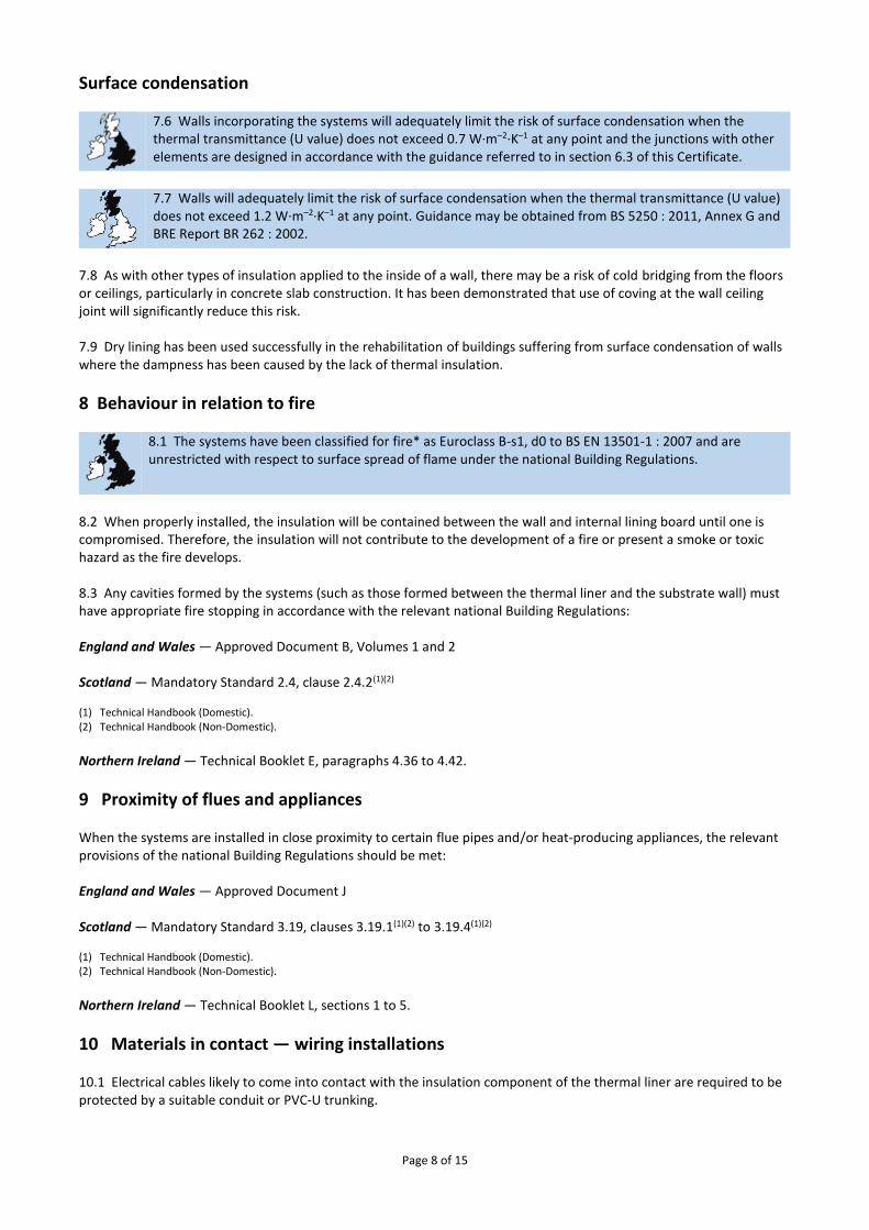
17 Finishing and detailing 17.1 To avoid thermal bridging, the systems should be used to line window reveals and suitable provisions will also need to be adopted at junctions and other details such as separating floors. Further guidance can be obtained from BRE Report BR 262 : 2002. 17.2 For windows, reveals and external angles, it is important to consider the junction of the installation to avoid thermal bridges. The board should be extended beyond the corner. The insulation is cut back to form a neat junction with the reveal board or wall lining. A bed of adhesive is applied and the cut board placed into it. Once the adhesive has dried, two nailable fixings should be installed half way up the board and 25 mm from each edge.
Page 12 of 15
Figure 4 Window reveal installation
17.3 When using Celotex PL4000, Celotex GD5000 and Celotex GS5000 there are a variety of thicknesses available. Thin solutions are available for specific use in door and window reveals. 17.4 For board joints, an appropriate joint filler should be firmly placed into the tapered edge, with tape then set into the filler. 17.5 Two or three applications of jointing compound are trowel-applied, allowing each to set before the next application. Each application should be feathered out beyond the previous application. Screws and nails should receive the same number of applications. 17.6 In circumstances where square edges meet, it will result in a raised profile. In these situations, the secondary application of joint filler should be omitted and the feathering extended to conceal the joint. 17.7 For internal angles, a jointing tape is creased into the corner and the same procedure used as for board edges. At external angles, an appropriate corner tape can be used or, where extra protection is required, an angle-bead used. 17.8 A finishing skim coat of 2 mm of plaster should be applied to complete the installation. Clean non-contaminated tools and materials should be used for this process. 17.9 Plaster is applied to the boards and joints with firm pressure. The joint adhesive should be firm but not quite set. Two applications should be used to achieve the final thickness of 2 mm. The second coat is applied onto a wet primary coat and trowelled to a smooth flat finish. 17.10 Once dry, the final surface is ready to be decorated. Consideration should be given to the need to prime the surface prior to painting or papering.
Technical Investigations
18 Tests Results of test data carried out on Celotex Plasterboard Thermal Laminates were assessed to determine: ● flatness of the composite plasterboard thermal laminate to BS EN 13950 : 2005 ● offset of the insulation over the plasterboard to BS EN 13950 : 2005 ● adhesion/cohesion of the insulating material to BS EN 13950 : 2005 ● soft body impact resistance of composite plasterboard thermal laminate to MOAT No 43 : 1987 ● hard body impact resistance of composite plasterboard thermal laminate to MOAT No 43 : 1987.

Page 13 of 15
19 Investigations 19.1 An assessment was made of the results of test data relating to: ● squareness ● vapour resistance ● density ● flatness ● dimension ● thermal conductivity ● dimensional stability at specific temperatures and humidity ● behaviour in relation to fire
● the declared lambda (λD) value ● thermal performance and condensation risk analysis were carried out. 19.2 The manufacturing process was evaluated, including methods for quality control, and details were obtained of the quality and composition of the materials used.

Page 14 of 15
Bibliography BS 5250 : 2011 Code of practice for control of condensation in buildings BS 6576 : 2005 Code of practice for diagnosis of rising damp in walls of buildings and installation of chemical damp-proof courses BS 8212 : 1995 Code of practice for dry lining and partitioning using gypsum plasterboard BS EN 13501-1 : 2007 Fire classification of construction products and building elements — Classification using test data from reaction to fire tests BS EN 13950 : 2005 Gypsum plasterboard thermal/acoustic insulation composite panels — Definitions, requirements and test methods BS EN 13963 : 2005 Jointing materials for gypsum plasterboards — Definitions, requirements and test methods BS EN 14195 : 2005 Metal framing components for gypsum plasterboard systems — Definitions, requirements and test methods BS EN 14353 : 2007 Metal beads and feature profiles for use with gypsum plasterboards — Definitions, requirements and test methods BS EN 14496 : 2005 Gypsum based adhesives for thermal/acoustic insulation composite panels and plasterboards —Definitions, requirements and test methods BS EN 14566 : 2008 Mechanical fasteners for gypsum plasterboard systems — Definitions, requirements and test methods BS EN ISO 6946 : 2007 Building components and building elements — Thermal resistance and thermal transmittance — Calculation method BS EN ISO 9001 : 2008 Quality management systems — Requirements BS EN ISO 13788 : 2012 Hygrothermal performance of building components and building elements — Internal surface temperature to avoid critical surface humidity and interstitial condensation — Calculation methods BS EN ISO 14001 : 2004 Environmental Management systems — Requirements with guidance for use BRE Digest 465: 2002 U values for light steel-frame construction BRE Report (BR 262 : 2002) Thermal insulation: avoiding risks BRE Report (BR 443 : 2006) Conventions for U-value calculations MOAT No 43 : 1987 UEAtc Directives for Impact Testing Opaque Vertical Building Components
Page 15 of 15
Conditions of Certification
20 Conditions 20.1 This Certificate:
relates only to the product/system that is named and described on the front page
is issued only to the company, firm, organisation or person named on the front page – no other company, firm, organisation or person may hold claim that this Certificate has been issued to them
is valid only within the UK
has to be read, considered and used as a whole document – it may be misleading and will be incomplete to be selective
is copyright of the BBA
is subject to English Law. 20.2 Publications, documents, specifications, legislation, regulations, standards and the like referenced in this Certificate are those that were current and/or deemed relevant by the BBA at the date of issue or reissue of this Certificate. 20.3 This Certificate will remain valid for an unlimited period provided that the product/system and its manufacture and/or fabrication, including all related and relevant parts and processes thereof: ● are maintained at or above the levels which have been assessed and found to be satisfactory by the BBA ● continue to be checked as and when deemed appropriate by the BBA under arrangements that it will determine ● are reviewed by the BBA as and when it considers appropriate. 20.4 The BBA has used due skill, care and diligence in preparing this Certificate, but no warranty is provided. 20.5 In issuing this Certificate the BBA is not responsible and is excluded from any liability to any company, firm, organisation or person, for any matters arising directly or indirectly from:
the presence or absence of any patent, intellectual property or similar rights subsisting in the product/system or any other product/system
the right of the Certificate holder to manufacture, supply, install, maintain or market the product/system
actual installations of the product/system, including their nature, design, methods, performance, workmanship and maintenance
any works and constructions in which the product/system is installed, including their nature, design, methods, performance, workmanship and maintenance
any loss or damage, including personal injury, howsoever caused by the product/system, including its manufacture, supply, installation, use, maintenance and removal
any claims by the manufacturer relating to CE marking. 20.6 Any information relating to the manufacture, supply, installation, use, maintenance and removal of this product/system which is contained or referred to in this Certificate is the minimum required to be met when the product/system is manufactured, supplied, installed, used, maintained and removed. It does not purport in any way to restate the requirements of the Health and Safety at Work etc. Act 1974, or of any other statutory, common law or other duty which may exist at the date of issue or reissue of this Certificate; nor is conformity with such information to be taken as satisfying the requirements of the 1974 Act or of any statutory, common law or other duty of care.
British Board of Agrément Bucknalls Lane Watford Herts WD25 9BA
©2015
tel: 01923 665300 fax: 01923 665301
[email protected] www.bbacerts.co.uk


![ICANCERRESEARCH56.4922-4926.NovemberI,1996 ...cancerres.aacrjournals.org/content/56/21/4922.full.pdf · ICANCERRESEARCH56.4922-4926.NovemberI,1996] ABSTRACT Phenolphthalein(atriphenylmethanederivative)hasbeencommonly](https://img.pdfslide.us/doc/110x75/5b8864627f8b9a46538dca9a/icancerresearch564922-4926novemberi1996-icancerresearch564922-4926novemberi1996.jpg)


![4926-Subversive Spinoza Uncontemporary Variations[1]](https://img.pdfslide.us/doc/110x75/577d33e91a28ab3a6b8c0e54/4926-subversive-spinoza-uncontemporary-variations1.jpg)