Embed Size (px)
Citation preview
Agreement
Concerning the Adoption of Uniform Technical Prescriptions for
Wheeled Vehicles, Equipment and Parts which can be Fitted and/or be
Used on Wheeled Vehicles and the Conditions for Reciprocal
Recognition of Approvals Granted on the Basis of these Prescriptions*
(Revision 2, including the amendments which entered into force on 16 October 1995)
_________
Addendum 127 – Regulation No. 128
Amendment 4
Supplement 4 to the original version of the Regulation – Date of entry into force:
8 October 2015
Uniform provisions concerning the approval of light emitting diode (LED) light sources for use in approved lamp units on power-driven vehicles and their trailers
This document is meant purely as documentation tool. The authentic and legal binding texts are:
- ECE/TRANS/WP.29/2015/33
- ECE/TRANS/WP.29/2015/33/Corr.1.
_________
UNITED NATIONS
* Former title of the Agreement: Agreement Concerning the Adoption of Uniform Conditions of
Approval and Reciprocal Recognition of Approval for Motor Vehicle Equipment and Parts, done at
Geneva on 20 March 1958.
E/ECE/324/Rev.2/Add.127/Amend.4−E/ECE/TRANS/505/Rev.2/Add.127/Amend.4
9 November 2015

E/ECE/324/Rev.2/Add.127/Amend.4
E/ECE/TRANS/505/Rev.2/Add.127/Amend.4
2
Paragraph 3.8., the table, amend to read:
"
S() S() S()
250 0.430 305 0.060 355 0.000 16
255 0.520 310 0.015 360 0.000 13
260 0.650 315 0.003 365 0.000 11
265 0.810 320 0.001 370 0.000 09
270 1.000 325 0.000 50 375 0.000 077
275 0.960 330 0.000 41 380 0.000 064
280 0.880 335 0.000 34 385 0.000 053
285 0.770 340 0.000 28 390 0.000 044
290 0.640 345 0.000 24 395 0.000 036
295 0.540 350 0.000 20 400 0.000 030
300 0.300
"
Annex 1,
The list of categories of LED light sources and their sheet numbers, amend to read:
" Category Sheet number(s)
LR1 LR1/1 to 5
LW2 LW2/1 to 5
LR3A LR3/1 to 5
LR3B LR3/1 to 5
LR4A LR4/1 to 5
LR4B LR4/1 to 5
"
The list of sheets for LED light sources and their sequence in this annex, amend to read:
" Sheet number(s)
LR1/1 to 5
LW2/1 to 5
LR3/1 to 5
LR4/1 to 5
"
After sheet LW2/5, insert new sheets LR3/1 to 5 and LR4/1 to 5, to read (see following pages; one page
per sheet):
E/ECE/324/Rev.2/Add.127/Amend.4
E/ECE/TRANS/505/Rev.2/Add.127/Amend.4
3
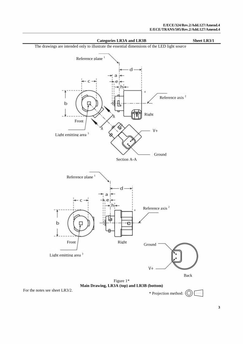
Categories LR3A and LR3B Sheet LR3/1
The drawings are intended only to illustrate the essential dimensions of the LED light source
Figure 1*
Main Drawing, LR3A (top) and LR3B (bottom)
For the notes see sheet LR3/2.
* Projection method:
Refe
renc
e
axis 2
Reference plane 1
Reference axis 2
Right
Right
Right
Front
Light emitting area 3
Ground
Section A-A
4
V+
Reference plane 1
Reference axis 2
Right
Front
Light emitting area 3
Ground
Back
4

E/ECE/324/Rev.2/Add.127/Amend.4
E/ECE/TRANS/505/Rev.2/Add.127/Amend.4
4
Categories LR3A and LR3B Sheet LR3/2
Table 1
Essential electrical and photometric characteristics of the LED light source
Dimensions
Production LED light sources Standard LED light sources
a mm 6.0 max.
b mm c + 10.0 min.
38.0 max.
c mm 18.5 ± 0.1
d mm 28.0 max.
e mm 3.0 ± 0.30 3.0 ± 0.15
h mm 5.5 + 0.0/ – 0.1
Cap PGJ18.5d-1 in accordance with IEC Publication 60061 (sheet 7004-185-1)
Electrical and photometric characteristics 5
Rated values Volts 12
Watts 3
Objective
Values 6
Watts
(at 13.5 V DC) 3.5 max. 3.5 max.
Luminous flux
(in lm at 13.5 V DC) 80 ± 20%
7 80 ± 10%
8
Luminous flux
(in lm at 9 V DC) 19 min.
1 The reference plane is the plane defined by the contact points of the cap-holder fit.
2 The reference axis is perpendicular to the reference plane and passing through the centre of the bayonet core.
3 Light emitting area: to be checked by means of the box system in Figure 2
4 A minimum free air space of 5mm around the light source shall be respected for convection.
5 The emitted light shall be red.
6 After continuous operation for 30 minutes at 23 ± 2.5° C.
7 The measured value shall be in between 100 per cent and 70 per cent of the value measured after 1 minute.
8 The measured value shall be in between 85 per cent and 75 per cent of the value measured after 1 minute.
Electrical characteristics
In case of LED light source failure (no light emitted) the max. electrical current draw, when operated between 12 V and
14 V, shall be less than 20 mA (open circuit condition).
E/ECE/324/Rev.2/Add.127/Amend.4
E/ECE/TRANS/505/Rev.2/Add.127/Amend.4
5
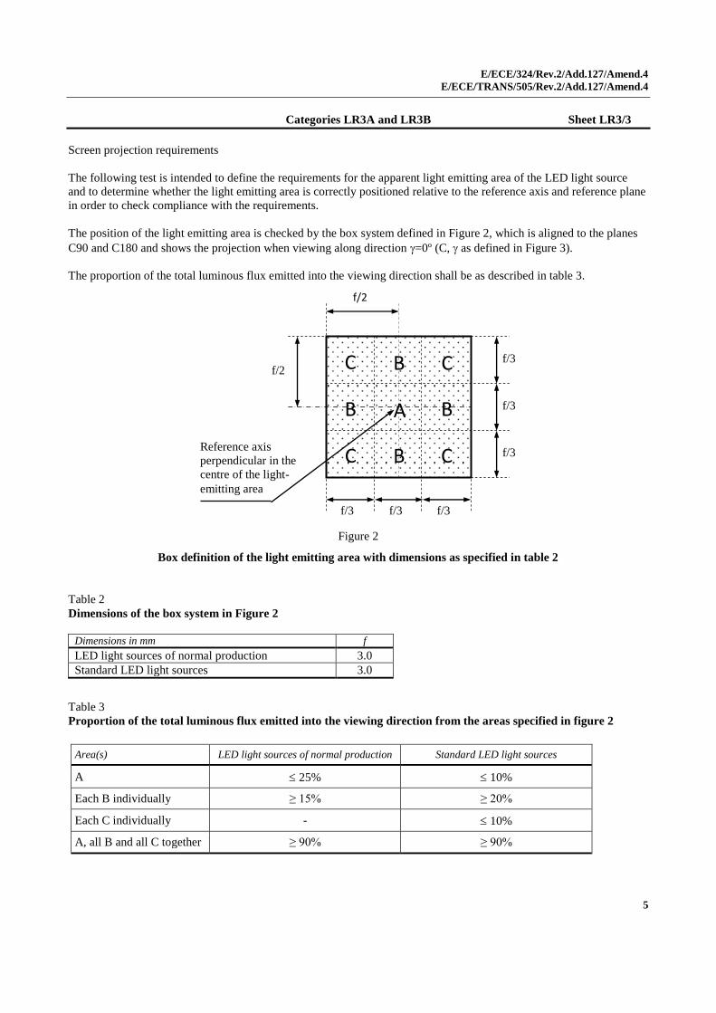
Categories LR3A and LR3B Sheet LR3/3
Screen projection requirements
The following test is intended to define the requirements for the apparent light emitting area of the LED light source
and to determine whether the light emitting area is correctly positioned relative to the reference axis and reference plane
in order to check compliance with the requirements.
The position of the light emitting area is checked by the box system defined in Figure 2, which is aligned to the planes
C90 and C180 and shows the projection when viewing along direction =0º (C, as defined in Figure 3).
The proportion of the total luminous flux emitted into the viewing direction shall be as described in table 3.
Figure 2
Box definition of the light emitting area with dimensions as specified in table 2
Table 2
Dimensions of the box system in Figure 2
Dimensions in mm f
LED light sources of normal production 3.0
Standard LED light sources 3.0
Table 3
Proportion of the total luminous flux emitted into the viewing direction from the areas specified in figure 2
Area(s) LED light sources of normal production Standard LED light sources
A 25% 10%
Each B individually ≥ 15% ≥ 20%
Each C individually - 10%
A, all B and all C together ≥ 90% ≥ 90%
f/3
Reference axis perpendicular in the centre of the light- emitting area
f/3
f/3
f/3
f/3 f/3
AA
BB
BB
BB
BB
CC
CC
CC
CC
f/2
f/2

E/ECE/324/Rev.2/Add.127/Amend.4
E/ECE/TRANS/505/Rev.2/Add.127/Amend.4
6
Categories LR3A and LR3B Sheet LR3/4
Normalized luminous intensity distribution
The following test is intended to determine the normalized luminous intensity distribution of the light source in an
arbitrary plane containing the reference axis. The intersection of the reference axis and the parallel plane to the
reference plane in distance e is used as the coordinate system origin.
The light source is mounted on a flat plate with the corresponding mounting lug features. The plate is mounted to the
goniometer table by a bracket, so that the reference axis of the light source lines up with one of the rotating axis of the
goniometer. The corresponding measurement set-up is described in Figure 3.
Luminous intensity data is recorded with a standard photo-goniometer. The measurement distance should be chosen
appropriately, to make sure that the detector is located in the far field of the light distribution.
The measurements shall be performed in C-planes C0/180 and C90/270, which contain the reference axis of the light
source. The test points for each plane for multiple polar angles are specified in Table 4.
After measurement the data shall be normalized to 1,000 lm according to Paragraph 3.1.11 using the luminous flux of
the individual light source under test. The data shall comply with the tolerance band as defined in Table 4.
The drawings are intended only to illustrate the essential set-up for measurement of the LED light source.
Figure 3
Set-up to measure the luminous intensity distribution, LR3A (top) and LR3B (bottom)
Reference axis
Reference plane
Photo-Detector of
Goniometer
C-plane definition
Viewing direction along reference
axis
Reference axis
Reference plane
Photo-Detector of
Goniometer
C-plane definition
Viewing direction along reference axis

E/ECE/324/Rev.2/Add.127/Amend.4
E/ECE/TRANS/505/Rev.2/Add.127/Amend.4
7
Categories LR3A and LR3B Sheet LR3/5
The light pattern as described in Table 4 shall be substantially uniform, i.e. in between two adjacent grid points the
relative luminous intensity requirement is calculated by linear interpolation using the two adjacent grid points. In case
of doubt this may be checked in addition to verification of the grid points given in table 4.
Table 4
Test point values of normalized intensities of normal production and standard lamps, respectively.
LED lamps of normal production Standard LED lamps
Angle Minimum Intensity
in cd /1000 lm
Maximum Intensity
in cd/1000 lm
Minimum Intensity
in cd /1000 lm
Maximum Intensity in
cd /1000 lm
-90° 0 38 0 25
-75° 0 160 0 140
-60° 98 246 127 220
-45° 142 305 181 275
-30° 169 352 213 315
-15° 192 389 239 340
0° 200 401 248 352
15° 192 389 239 340
30° 169 352 213 315
45° 142 305 181 275
60° 98 246 127 220
75° 0 160 0 140
90° 0 38 0 25

E/ECE/324/Rev.2/Add.127/Amend.4
E/ECE/TRANS/505/Rev.2/Add.127/Amend.4
8
Categories LR4A and LR4B Sheet LR4/1
The drawings are intended only to illustrate the essential dimensions of the LED light source
Figure 1*
Main Drawing, LR4A (top) and LR4B (bottom)
For the notes see sheet LR4/2. * Projection method:
Reference plane 1
Reference axis 2
Right
Light emitting area 3
Front
Ground
Section A-A
Major function
Minor function
4
Reference plane 1
Reference axis 2
Right
Major function
Minor function
Ground
Light emitting area 3
Back
Front
4

E/ECE/324/Rev.2/Add.127/Amend.4
E/ECE/TRANS/505/Rev.2/Add.127/Amend.4
9
Categories LR4A and LR4B Sheet LR4/2
Table 1
Essential electrical and photometric characteristics of the LED light source
Dimensions
Production LED light sources Standard LED light sources
a mm 6.0 max.
b mm c + 10.0 min.
38.0 max.
c mm 18.5 ± 0.1
d mm 28.0 max.
e mm 3.0 ± 0.30 3.0 ± 0.15
h mm 5.5 + 0.0/ – 0.1
Cap PGJ18.5t-5 in accordance with IEC Publication 60061 (sheet 7004-185-1)
Electrical and photometric characteristics 5
Rated values
Minor function Major function Minor function Major function
Volts 12 12
Watts 0.75 3 0.75 3
Objective
Values 6
Watts
(at 13.5 V DC) 1.0 max. 3.5 max. 1.0 max. 3.5 max.
Luminous flux
(in lm at 13.5 V DC) 6 ± 20% 80 ± 20%
7 6 ± 10% 80 ± 10%
8
Luminous flux
(in lm at 9 V DC) 1.5 min. 19 min.
1 The reference plane is the plane defined by the contact points of the cap-holder fit.
2 The reference axis is perpendicular to the reference plane and passing through the centre of the Bayonet core.
3 Light emitting area: to be checked by means of the box system in Figure 2
4 A minimum free air space of 5mm around the light source shall be respected for convection.
5 The emitted light shall be red.
6 After continuous operation for 30 minutes at 23 ± 2.5° C.
7 The measured value shall be in between 100 per cent and 70 per cent of the value measured after 1 minute.
8 The measured value shall be in between 85 per cent and 75 per cent of the value measured after 1 minute.
Electrical characteristics
In case of LED light source failure (no light emitted) the max. electrical current draw, when operated between 12 V and
14 V, shall be less than 20 mA (open circuit condition).
The major and the minor function shall be operated by separate electrical circuits.
E/ECE/324/Rev.2/Add.127/Amend.4
E/ECE/TRANS/505/Rev.2/Add.127/Amend.4
10
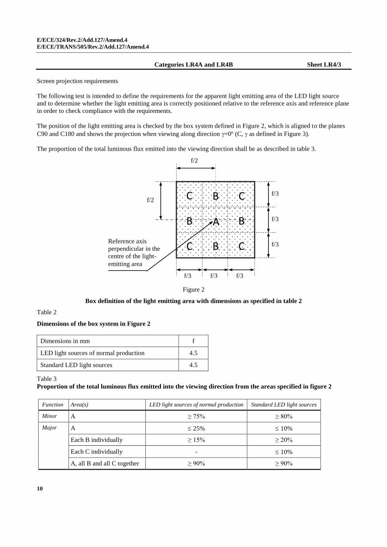
Categories LR4A and LR4B Sheet LR4/3
Screen projection requirements
The following test is intended to define the requirements for the apparent light emitting area of the LED light source
and to determine whether the light emitting area is correctly positioned relative to the reference axis and reference plane
in order to check compliance with the requirements.
The position of the light emitting area is checked by the box system defined in Figure 2, which is aligned to the planes
C90 and C180 and shows the projection when viewing along direction =0º (C, as defined in Figure 3).
The proportion of the total luminous flux emitted into the viewing direction shall be as described in table 3.
Figure 2
Box definition of the light emitting area with dimensions as specified in table 2
Table 2
Dimensions of the box system in Figure 2
Dimensions in mm f
LED light sources of normal production 4.5
Standard LED light sources 4.5
Table 3
Proportion of the total luminous flux emitted into the viewing direction from the areas specified in figure 2
Function Area(s) LED light sources of normal production Standard LED light sources
Minor A ≥ 75% ≥ 80%
Major A 25% 10%
Each B individually ≥ 15% ≥ 20%
Each C individually - 10%
A, all B and all C together ≥ 90% ≥ 90%
f/3
Reference axis perpendicular in the centre of the light- emitting area
f/3
f/3
f/3
f/3 f/3
AA
BB
BB
BB
BB
CC
CC
CC
CC
f/2
f/2

E/ECE/324/Rev.2/Add.127/Amend.4
E/ECE/TRANS/505/Rev.2/Add.127/Amend.4
11
Categories LR4A and LR4B Sheet LR4/4
Normalized luminous intensity distribution
The following test is intended to determine the normalized luminous intensity distribution of the light source in an
arbitrary plane containing the reference axis. The intersection of the reference axis and the parallel plane to the
reference plane in distance e is used as the coordinate system origin.
The light source is mounted on a flat plate with the corresponding mounting lug features. The plate is mounted to the
goniometer table by a bracket, so that the reference axis of the light source lines up with one of the rotating axis of the
goniometer. The corresponding measurement set-up is described in Figure 3.
Luminous intensity data is recorded with a standard photo-goniometer. The measurement distance should be chosen
appropriately, to make sure that the detector is located in the far field of the light distribution.
The measurements shall be performed in C-planes C0/180 and C90/270, which contain the reference axis of the light
source. The test points for each plane for multiple polar angles are specified in Table 4.
After measurement the data shall be normalized to 1000 lm according to Paragraph 3.1.11 using the luminous flux of
the individual light source under test. The data shall comply with the tolerance band as defined in Table 4.
The drawings are intended only to illustrate the essential set-up for measurement of the LED light source
Figure 3
Set-up to measure the luminous intensity distribution, LR4A (top) and LR4B (bottom)
Reference axis
Reference plane
Photo-Detector of
Goniometer
C-plane definition
Viewing direction along reference axis
Reference axis
Reference plane
Photo-Detector of
Goniometer
C-plane definition
Viewing direction along reference
axis

E/ECE/324/Rev.2/Add.127/Amend.4
E/ECE/TRANS/505/Rev.2/Add.127/Amend.4
12
Categories LR4A and LR4B Sheet LR4/5
The light pattern as described in Table 4 shall be substantially uniform, i.e. in between two adjacent grid points the
relative luminous intensity requirement is calculated by linear interpolation using the two adjacent grid points. In case
of doubt this may be checked in addition to verification of the grid points given in Table 4.
Table 4
Test point values of normalized intensities of normal production and standard lamps, respectively.
Requirements apply to both, major and minor function.
LED lamps of normal production Standard LED lamps
Angle Minimum Intensity in cd /1000lm
Maximum Intensity in cd/1000lm
Minimum Intensity in cd /1000lm
Maximum Intensity in cd/1000lm
-90° 0 38 0 25
-75° 0 160 0 140
-60° 98 246 127 220
-45° 142 305 181 275
-30° 169 352 213 315
-15° 192 389 239 340
0° 200 401 248 352
15° 192 389 239 340
30° 169 352 213 315
45° 142 305 181 275
60° 98 246 127 220
75° 0 160 0 140
90° 0 38 0 25
E/ECE/324/Rev.2/Add.127/Amend.4
E/ECE/TRANS/505/Rev.2/Add.127/Amend.4
13
Annex 4,
Paragraph 1.2., amend to read:
"1.2. The luminous flux values, as measured after
(a) 30 minutes, or
(b) Stabilisation of temperature Tb
shall comply with the minimum and maximum requirements.
In case of (a), unless otherwise specified on the data sheet, this value shall be
in between 100 per cent and 80 per cent of the value measured after 1
minute."