Embed Size (px)
Citation preview
GE.12-
Agreement
Concerning the adoption of uniform technical prescriptions
for wheeled vehicles, equipment and parts which can be fitted
and/or be used on wheeled vehicles and the conditions for reciprocal
recognition of approvals granted on the basis of these prescriptions*
(Revision 2, including the amendments which entered into force on 16 October 1995)
_________
Addendum 36: Regulation No. 37
Revision 7
Incorporating all valid text up to:
Supplement 37 to the 03 series of amendments - Date of entry into force: 28 October 2011
Corrigendum 1 to Revision 6 of the Regulation - Date of entry into force: 14 March 2012
Uniform provisions concerning the approval of filament lamps for use
in approved lamp units of power-driven vehicles and of their trailers ___________
UNITED NATIONS
* Former title of the Agreement: Agreement concerning the adoption of uniform conditions of approval
and reciprocal recognition of approval for motor vehicle equipment and parts, done at Geneva on
20 March 1958.
E/ECE/324/Rev.1/Add.36/Rev.7−E/ECE/TRANS/505/Rev.1/Add.36/Rev.7
3 July 2012

E/ECE/324/Rev.1/Add.36/Rev.7
E/ECE/TRANS/505/Rev.1/Add.36/Rev.7
3
Regulation No. 37
Uniform provisions concerning the approval of filament lamps for use in approved lamp units of power-driven vehicles and of their trailers
Contents
Page
1. Scope ................................................................................................................................................ 4
2. Administrative provisions ................................................................................................................ 4
3. Technical requirements .................................................................................................................... 6
4. Conformity of production ................................................................................................................. 10
5. Penalties for non-conformity of production ..................................................................................... 11
6. Production definitively discontinued ................................................................................................ 12
7. Names and addresses of Technical Services responsible for conducting approval
tests, and of Type Approval Authorities........................................................................................... 12
8. Transitional provisions ..................................................................................................................... 12
Annexes
1 Sheets for filament lamps ................................................................................................................. 14
2 Communication ................................................................................................................................ 176
3 Example of the arrangement of the approval mark .......................................................................... 178
4 Luminous centre and shapes of filament lamps................................................................................ 179
5 Checking the colour of filament lamps ............................................................................................ 180
6 Minimum requirements for quality control procedures by the manufacturer ................................... 182
7 Sampling and compliance levels for manufacturer test records ....................................................... 183
8 Minimum requirements for spot checks by theType Approval Authority ........................................ 187
9 Compliance approved by spot check ............................................................................................... 188
E/ECE/324/Rev.1/Add.36/Rev.7
E/ECE/TRANS/505/Rev.1/Add.36/Rev.7
4
1. Scope
This Regulation applies to filament lamps shown in Annex 1 and intended for
use in approved lamp units of power-driven vehicles and of their trailers.
2. Administrative provisions
2.1. Definitions
2.1.1. Definition of "category"
The term "category" is used in this Regulation to describe different basic
design of standardised filament lamps. Each category has a specific
designation, as for example: "H4", "P21W", "T4W", "PY21W"or "RR10W".
2.1.2. Definition of "type"
Filament lamps of different1 "types" are filament lamps within the same
category which differ in such essential respects as:
2.1.2.1. Trade name or mark (Filament lamps bearing the same trade name or mark
but produced by different manufacturers are considered as being of different
types. Filament lamps produced by the same manufacturer differing only by
the trade name or mark may be considered to be of the same type);
2.1.2.2. Bulb design and/or cap design, in so far as these differences affect the optical
results;
2.1.2.3. Rated voltage;
2.1.2.4. Halogen.
2.2. Application for approval
2.2.1. Application for approval shall be submitted by the owner of the trade name
or mark, or by his duly accredited representative.
2.2.2. Every application for approval shall be accompanied (see also
paragraph 2.4.2.) by:
2.2.2.1. Drawings in triplicate, sufficiently detailed to permit identification of the
type;
2.2.2.2. A brief technical description;
2.2.2.3. Five samples of each colour which has been applied for;
2.2.3. In the case of a type of filament lamp differing only by the trade name or
mark from a type that has already been approved it shall be sufficient to
submit:
1 A selective-yellow bulb or an additional selective-yellow outer bulb, solely intended to change the
colour but not the other characteristics of a filament lamp emitting white light, does not constitute a
change of type of the filament lamp.
E/ECE/324/Rev.1/Add.36/Rev.7
E/ECE/TRANS/505/Rev.1/Add.36/Rev.7
5
2.2.3.1. A declaration by the manufacturer that the type submitted is identical (except
in the trade name or mark) with and has been produced by the same
manufacturer as, the type already approved, the latter being identified by its
approval code;
2.2.3.2. Two samples bearing the new trade name or mark.
2.2.4. The competent authority shall verify the existence of satisfactory
arrangements for ensuring effective control of the conformity of production
before type approval is granted.
2.3. Inscriptions
2.3.1. Filament lamps submitted for approval shall bear on the cap or bulb2:
2.3.1.1. The trade name or mark of the applicant;
2.3.1.2. The rated voltage. However, for filament lamps for which only a 12 V type is
standardised and the maximum allowed bulb diameter of which does not
exceed 7.5 mm, the rated voltage need not be marked;
2.3.1.3. The international designation of the relevant category. The wattage character
"W" of this designation need not be marked when the maximum allowed bulb
diameter of the filament lamp type does not exceed 7.5 mm;
2.3.1.4. The rated wattage (in the sequence, high wattage/low wattage filament for
dual-filament lamps); this need not be indicated separately if it is part of the
international designation of the relevant filament lamp category;
2.3.1.5. A space of sufficient size to accommodate the approval mark.
2.3.2. The space mentioned in paragraph 2.3.1.5. above shall be indicated in the
drawings accompanying the application for approval.
2.3.3. Halogen filament lamps meeting the requirements of paragraph 3.7. below
shall be marked with a "U".
2.3.4. Inscriptions other than those covered by paragraphs 2.3.1. and 2.4.3. may be
affixed, on the condition that they do not adversely affect the luminous
characteristics.
2.4. Approval
2.4.1. If all samples of a type of filament lamp which are submitted in pursuance of
paragraphs 2.2.2.3. or 2.2.3.2. above meet the requirements of this
Regulation, approval shall be granted.
2.4.2. An approval code shall be assigned to each type approved. Its first character
(at present 2, corresponding to the 02 series of amendments which entered
into force on 27 October 1983 and to the 03 series of amendments (not
requiring changes in the approval number), which entered into force on
1 June 1984) shall indicate the series of amendments incorporating the most
recent major technical amendments made to the Regulation at the time of
issue of the approval. This will be followed by an identification code
comprising not more than two characters. Only the Arabic numerals and
capital letters listed in footnote3 shall be used. The same Contracting Party
2 In the latter case, the luminous characteristics shall not be adversely affected.
3 0 1 2 3 4 5 6 7 8 9
A B C D E F G H J K L M N P R S T U V W X Y Z
E/ECE/324/Rev.1/Add.36/Rev.7
E/ECE/TRANS/505/Rev.1/Add.36/Rev.7
6
may not assign the same code to another type of filament lamp. Notice of
approval or of extension or refusal or withdrawal of approval or production
definitively discontinued of a type of filament lamp pursuant to this
Regulation shall be communicated to the Parties of the Agreement which
apply this Regulation by means of a form conforming to the model in
Annex 2 to this Regulation and of a drawing, supplied by the applicant for
approval in a format not exceeding A4 (210 x 297 mm) and on a scale of at
least 2: 1. If the applicant so desires, the same approval code may be
assigned to the filament lamp emitting white light and to the filament lamp
emitting selective-yellow light (see para. 2.1.2.3.).
2.4.3. To every filament lamp conforming to a type approved under this Regulation
there shall be affixed in the space referred to in paragraph 2.3.1.5., in addition
to the inscriptions required under paragraph 2.3.1., an international approval
mark consisting of:
2.4.3.1. A truncated circle surrounding the letter "E" followed by the distinguishing
number of the country which has granted approval4;
2.4.3.2. The approval code, placed close to the truncated circle.
2.4.4. If the applicant has obtained the same approval code for several trade names
or marks, one or more of them will suffice to meet the requirements of
paragraph 2.3.1.1.
2.4.5. The marks and inscriptions specified in paragraphs 2.3.1. and 2.4.3. shall be
clearly legible and be indelible.
2.4.6. Annex 3 to this Regulation gives an example of arrangement of the approval
mark.
3. Technical requirements
3.1. Definitions
3.1.1. Rated voltage: voltage (in volts) marked on the filament lamp;
3.1.2. Rated wattage: wattage (in watts) marked on the filament lamp which may be
incorporated into the international designation of the relevant category;
3.1.3. Test voltage: voltage, at the filament lamp terminals for which the electrical
and photometric characteristics of the filament lamp are intended and are to
be tested.
3.1.4. Objective values: values to be achieved, within the specified tolerances, when
the filament lamp is supplied with current at its test voltage;
3.1.5. Standard (étalon) filament lamp: a filament lamp emitting white or amber or
red light with reduced dimensional tolerances, used for the photometric
testing of lighting and light-signalling devices. Standard filament lamps are
specified in only one voltage rating for each category;
4 The distinguish numbers of the Contracting Parties to the 1958 Agreement are reproduced in
Annex 3 to Consolidated Resolution on the Construction of Vehicles (R.E.3), document
TRANS/WP.29/78/Rev.2/Amend.1.
E/ECE/324/Rev.1/Add.36/Rev.7
E/ECE/TRANS/505/Rev.1/Add.36/Rev.7
7
3.1.6. Reference luminous flux: specified luminous flux of a standard filament lamp
to which the optical characteristics of a lighting device shall be referred;
3.1.7. Measuring luminous flux: specified value of the luminous flux for testing a
filament lamp in a standard headlamp as specified in paragraph 3.8.;
3.1.8. Reference axis: an axis defined with reference to the cap and to which certain
dimensions of the filament lamp are referred;
3.1.9. Reference plane: a plane defined with reference to the cap and to which
certain dimensions of the filament lamp are referred.
3.1.10. Filament light source (filament lamp): a light source where the element for
visible radiation is one or more heated filaments producing thermal radiation.
3.2. General specifications
3.2.1. Each sample submitted shall conform to the relevant specifications of this
Regulation.
3.2.2. Filament lamps shall be so designed as to be and to remain in good working
order when in normal use. They shall moreover exhibit no fault in design or
manufacture.
3.2.3. The filament(s) as specified in the data sheet of the relevant category in
Annex 1 shall be the only element(s) of the filament lamp that generate and
emit light when energised.
3.3. Manufacture
3.3.1. Filament lamp bulbs shall exhibit no scores or spots which might impair their
efficiency and their optical performance.
3.3.2. Filament lamps shall be equipped with standard caps complying with the cap
data sheets of IEC Publication 60061, third edition, as specified on the
individual data sheets of Annex 1.
3.3.3. The cap shall be strong and firmly secured to the bulb.
3.3.4. To ascertain whether filament lamps conform to the requirements of
paragraphs 3.3.1. to 3.3.3. above, a visual inspection, a dimension check and,
where necessary, a trial fitting shall be carried out.
3.4. Tests
3.4.1. Filament lamps shall first be aged at their test voltage for approximately one
hour. For dual-filament lamps, each filament shall be aged separately. In the
case of filament lamps, for which more than one test voltage is specified, the
highest test voltage value shall be used for ageing.
3.4.2. In the case of a filament lamp having a coated bulb, after the ageing period
corresponding to paragraph 3.4.1., the surface of the bulb shall be lightly
wiped with a cotton cloth soaked in a mixture of 70 vol. per cent of n-heptane
and 30 vol. per cent of toluol. After about five minutes, the surface shall be
inspected visually. It shall not show any apparent changes.
3.4.3. The position and dimensions of the filament shall be measured with the
filament lamps being supplied with current at from 90 per cent to 100 per
cent of the test voltage. In the case of filament lamps, for which more than
one test voltage is specified, the highest test voltage value shall be used for
measurement of the position and dimensions of the filament.
E/ECE/324/Rev.1/Add.36/Rev.7
E/ECE/TRANS/505/Rev.1/Add.36/Rev.7
8
3.4.4. Unless otherwise specified, electrical and photometric measurements shall be
carried out at the test voltage(s).
3.4.5. Electrical measurements shall be carried out with instruments of at least
class 0.2.
3.4.6. The luminous flux (in lumen) specified on the filament lamp data sheets of
Annex 1 is valid for filament lamps emitting white light unless a special
colour is stated there.
In the case where the selective-yellow colour is allowed, the luminous flux of
the filament lamp with the selective-yellow outer bulb shall be at least 85 per
cent of the specified luminous flux of the relevant filament lamp emitting
white light.
3.5. Filament position and dimensions
3.5.1. The geometric shapes of the filament shall in principle be as specified on the
filament lamp data sheets of Annex 1.
3.5.2. For line filaments the correct position and shape shall be checked as specified
in the relevant data sheets.
3.5.3. If the filament is shown on the filament lamp data sheet in at least one view
as a point, the position of the luminous centre shall be determined in
conformity with Annex 4.
3.5.4. The length of a line filament shall be determined by its ends, defined - unless
otherwise specified on the relevant data sheet - as the apices of the first and
the last filament turn as seen in projection perpendicular to the reference axis
of the filament lamp. Such an apex shall comply with the requirement that
the angle formed by the legs shall not exceed 90°. In the case of coiled-coil
filaments the apices of the secondary turns shall be taken into account.
3.5.4.1. For axial filaments the extreme position of the apices considered shall be
determined by rotating the filament lamp about its reference axis. The length
shall then be measured in a direction parallel to the reference axis.
3.5.4.2. For transverse filaments the filament axis shall be placed perpendicular to the
direction of projection. The length shall be measured in a direction
perpendicular to the reference axis.
3.6. Colour
3.6.1. The colour of the light emitted by the filament lamp shall be white unless
otherwise specified on the relevant data sheet.
3.6.2. The definitions of the colour of the light emitted, given in Regulation No. 48
and its series of amendments in force at the time of application for type
approval, shall apply to this Regulation.
3.6.3. The colour of the light emitted shall be measured by the method specified in
Annex 5. Each measured value shall lie within the required tolerance area5.
Moreover, in the case of filament lamps emitting white light, the measured
values shall not deviate more than 0.020 unit in the x and/or y direction from
5 For Conformity of Production purposes of amber and red colour only, at least 80 per cent of the
measuring results shall lie within the required tolerance area.
E/ECE/324/Rev.1/Add.36/Rev.7
E/ECE/TRANS/505/Rev.1/Add.36/Rev.7
9
a point of choice on the Planckian locus (IEC Publication 15.2 Colorimetry,
1986). Filament lamps for use in light signalling devices shall meet the
requirements as specified in paragraph 2.4.2. of IEC Publication 60809,
Amendment 5 to Edition 2.
3.7. UV radiation
The UV radiation of a halogen lamp shall be such that:
400 nm
∫ Ee()∙d
=315 nm
k1 = ____________________ ≤ 2 ∙ 10-4 W/lm
780 nm
km ∙ ∫ Ee()∙V()∙d
=380 nm
315 nm
∫ Ee()∙d
=250 nm
k2 = ____________________ ≤ 2 ∙ 10-6 W/lm
780 nm
km ∙ ∫ Ee()∙V()∙d
=380 nm
where:
Ee () (W/nm) is the spectral distribution of the radiant flux;
V () (1) is the spectral luminous efficiency;
km = 683 (lm/W) is the photometric radiation equivalent;
(nm) is the wave length.
This value shall be calculated using intervals of five nanometres.
3.8. Observation concerning selective-yellow colour
An approval of a filament lamp type under this Regulation may be granted,
pursuant to paragraph 3.6. above, for a filament lamp emitting white light as
well as selective-yellow light; Article 3 of the Agreement to which this
Regulation is annexed shall not prevent the Contracting Parties from
prohibiting, on vehicles registered by them, filament lamps emitting either
white or selective-yellow light.
3.9. Check on optical quality
(Applies only to filament lamps of categories R2, H4 and HS1).
3.9.1. This check on optical quality shall be carried out at a voltage such that the
measuring luminous flux is obtained; the specifications of paragraph 3.4.6.
are to be observed accordingly.
3.9.2. For 12-Volt filament lamps emitting white light:
The sample which most nearly conforms to the requirements laid down for the
standard filament lamp shall be tested in a standard headlamp as specified in
paragraph 3.9.5. and it shall be verified whether the assembly comprising the
aforesaid headlamp and the filament lamp being tested meets the light-
distribution requirements laid down for the passing beam in the relevant
Regulation.
E/ECE/324/Rev.1/Add.36/Rev.7
E/ECE/TRANS/505/Rev.1/Add.36/Rev.7
10
3.9.3. For 6-Volt and 24-Volt filament lamps emitting white light:
The sample which most nearly conforms to the nominal dimension values
shall be tested in a standard headlamp as specified in paragraph 3.9.5. and it
shall be verified whether the assembly comprising the aforesaid headlamp
and the filament lamp being tested meets the light-distribution requirements
laid down for the passing beam in the relevant Regulation. Deviations not
exceeding 10 per cent of the minimum values will be acceptable.
3.9.4. Filament lamps emitting selective-yellow light shall be tested in the same
manner as described in paragraphs 3.9.2. and 3.9.3. in a standard headlamp as
specified in paragraph 3.9.5. to ensure that the illumination complies with at
least 85 per cent for 12-Volt filament lamps, and at least 77 per cent for
6-Volt and 24-Volt filament lamps, with the minimum values of the light-
distribution requirements laid down for the passing beam in the relevant
Regulation. The maximum illumination limits remain unchanged.
In the case of a filament lamp having a selective-yellow bulb, this test shall
be left out if the approval is also given to the same type of filament lamp
emitting white light.
3.9.5. A headlamp shall be deemed to be a standard headlamp if:
3.9.5.1. It satisfies the pertinent conditions of approval;
3.9.5.2. It has an effective diameter of not less than 160 mm;
3.9.5.3. With a standard filament lamp it produces at the various points and in the
various zones specified for the headlamp type concerned, illumination equal to:
3.9.5.3.1. Not more than 90 per cent of the maximum limits;
3.9.5.3.2. Not less than 120 per cent of the minimum limits prescribed for the headlamp
type concerned.
3.10. Standard filament lamps
Additional requirements for standard (étalon) filament lamps are given on the
relevant data sheets of Annex 1.
Bulbs of standard (étalon) filament lamps emitting white light shall not alter
the CIE trichromatic coordinates of a luminous source having a colour
temperature of 2,856 K by more than 0.010 units in the x and/or y direction.
For standard (étalon) filament lamps emitting amber or red light, changes of
the bulb temperature shall not affect the luminous flux which might impair
photometric measurements of signalling devices.
4. Conformity of production
4.1. Filament lamps approved to this Regulation shall be so manufactured as to
conform to the type approved by meeting the inscriptions and technical
requirements set forth in paragraph 3. above and Annexes 1, 3 and 4 to this
Regulation.
4.2. In order to verify that the requirements of paragraph 4.1. are met, suitable
controls of the production shall be carried out.
E/ECE/324/Rev.1/Add.36/Rev.7
E/ECE/TRANS/505/Rev.1/Add.36/Rev.7
11
4.3. The holder of the approval shall in particular:
4.3.1. Ensure existence of procedures for the effective control of the quality of
products,
4.3.2. Have access to the control equipment necessary for checking the conformity
to each approved type,
4.3.3. Ensure that data of test results are recorded and that related documents shall
remain available for a period to be determined in accordance with the
administrative service,
4.3.4. Analyse the results of each type of test, applying criteria of Annex 7, in order
to verify and ensure the stability of the product characteristics making
allowance for variation of an industrial production,
4.3.5. Ensure that for each type of filament lamp, at least the tests prescribed in
Annex 6 to this Regulation are carried out,
4.3.6. Ensure that any collecting of samples giving evidence of non-conformity
with the type of test considered shall give rise to another sampling and
another test. All the necessary steps shall be taken to re-establish the
conformity of the corresponding production.
4.4. The competent authority which has granted type-approval may at any time
verify the conformity control methods applicable to each production unit.
4.4.1. In every inspection, the test books and production survey records shall be
presented to the visiting inspector.
4.4.2. The inspector may take samples at random which will be tested in the
manufacturer's laboratory. The minimum number of samples may be
determined according to the results of the manufacturer's own verification.
4.4.3. When the quality level appears unsatisfactory or when it seems necessary to
verify the validity of the tests carried out in application of paragraph 4.4.2.
above, the inspector shall select samples, to be sent to the Technical Service
which has conducted the type approval tests.
4.4.4. The competent authority may carry out any tests prescribed in this
Regulation. Where the competent authority decides to carry out spot checks,
criteria of Annexes 8 and 9 to this Regulation shall be applied.
4.4.5. The normal frequency of inspection authorised by the competent authority shall
be one every two years. In the case where negative results are recorded during
one of these visits, the competent authority shall ensure that all necessary steps
are taken to re-establish the conformity of production as rapidly as possible.
5. Penalties for non-conformity of production
5.1. The approval granted in respect of a filament lamp pursuant to this
Regulation may be withdrawn if the requirements are not met or if a filament
lamp bearing the approval mark does not conform to the type approved.
5.2. If a Contracting Party to the Agreement applying this Regulation withdraws
an approval it has previously granted, it shall forthwith so notify the other
Contracting Parties applying this Regulation, by means of a communication
form conforming to the model in Annex 2 to this Regulation.
E/ECE/324/Rev.1/Add.36/Rev.7
E/ECE/TRANS/505/Rev.1/Add.36/Rev.7
12
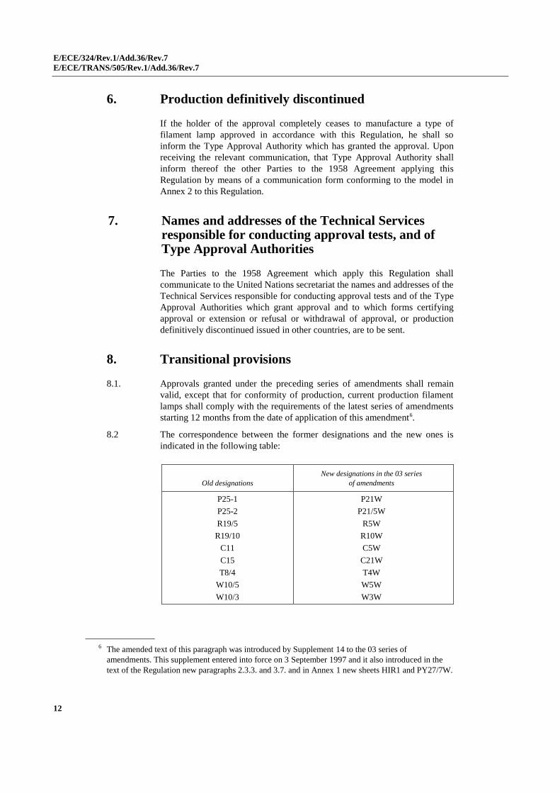
6. Production definitively discontinued
If the holder of the approval completely ceases to manufacture a type of
filament lamp approved in accordance with this Regulation, he shall so
inform the Type Approval Authority which has granted the approval. Upon
receiving the relevant communication, that Type Approval Authority shall
inform thereof the other Parties to the 1958 Agreement applying this
Regulation by means of a communication form conforming to the model in
Annex 2 to this Regulation.
7. Names and addresses of the Technical Services responsible for conducting approval tests, and of Type Approval Authorities
The Parties to the 1958 Agreement which apply this Regulation shall
communicate to the United Nations secretariat the names and addresses of the
Technical Services responsible for conducting approval tests and of the Type
Approval Authorities which grant approval and to which forms certifying
approval or extension or refusal or withdrawal of approval, or production
definitively discontinued issued in other countries, are to be sent.
8. Transitional provisions
8.1. Approvals granted under the preceding series of amendments shall remain
valid, except that for conformity of production, current production filament
lamps shall comply with the requirements of the latest series of amendments
starting 12 months from the date of application of this amendment6.
8.2 The correspondence between the former designations and the new ones is
indicated in the following table:
Old designations
New designations in the 03 series
of amendments
P25-1
P25-2
R19/5
R19/10
C11
C15
T8/4
W10/5
W10/3
P21W
P21/5W
R5W
R10W
C5W
C21W
T4W
W5W
W3W
6 The amended text of this paragraph was introduced by Supplement 14 to the 03 series of
amendments. This supplement entered into force on 3 September 1997 and it also introduced in the
text of the Regulation new paragraphs 2.3.3. and 3.7. and in Annex 1 new sheets HIR1 and PY27/7W.
E/ECE/324/Rev.1/Add.36/Rev.7
E/ECE/TRANS/505/Rev.1/Add.36/Rev.7
13
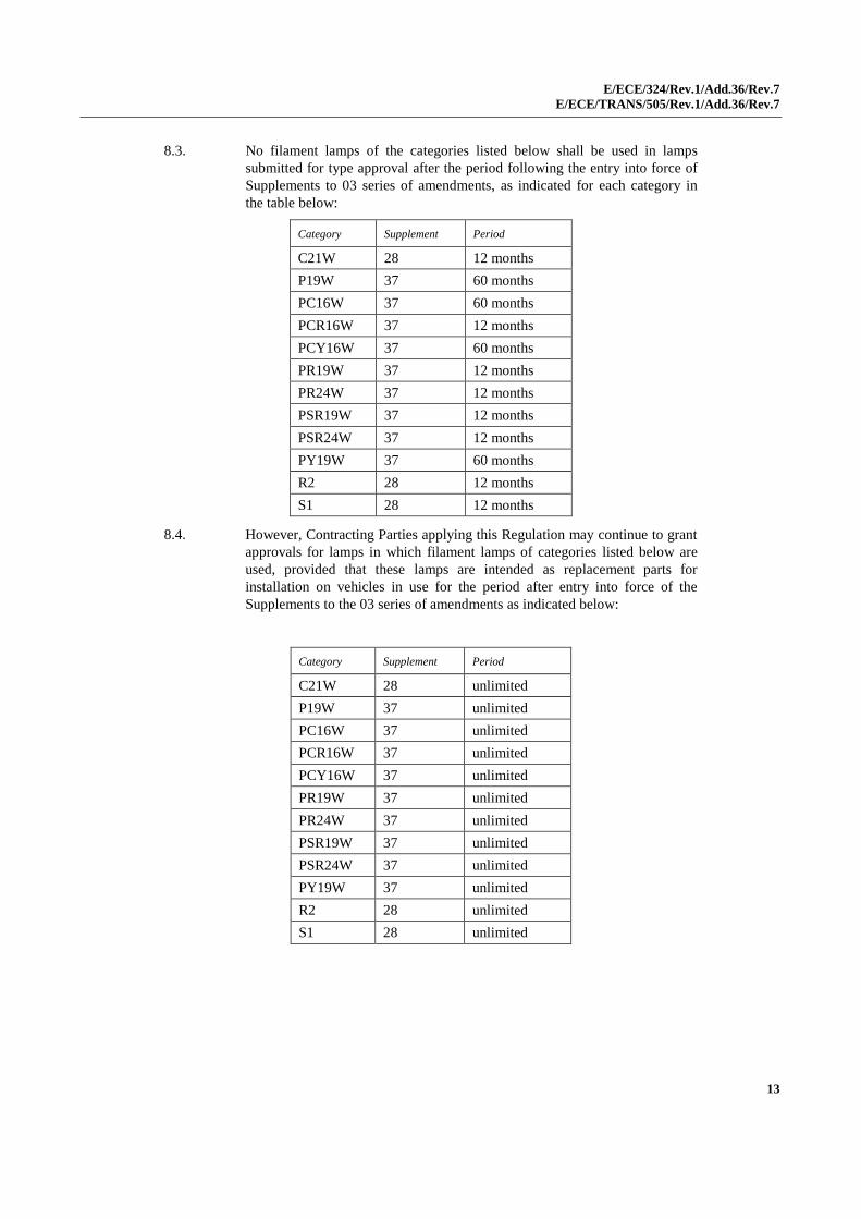
8.3. No filament lamps of the categories listed below shall be used in lamps
submitted for type approval after the period following the entry into force of
Supplements to 03 series of amendments, as indicated for each category in
the table below:
Category Supplement Period
C21W 28 12 months
P19W 37 60 months
PC16W 37 60 months
PCR16W 37 12 months
PCY16W 37 60 months
PR19W 37 12 months
PR24W 37 12 months
PSR19W 37 12 months
PSR24W 37 12 months
PY19W 37 60 months
R2 28 12 months
S1 28 12 months
8.4. However, Contracting Parties applying this Regulation may continue to grant
approvals for lamps in which filament lamps of categories listed below are
used, provided that these lamps are intended as replacement parts for
installation on vehicles in use for the period after entry into force of the
Supplements to the 03 series of amendments as indicated below:
Category Supplement Period
C21W 28 unlimited
P19W 37 unlimited
PC16W 37 unlimited
PCR16W 37 unlimited
PCY16W 37 unlimited
PR19W 37 unlimited
PR24W 37 unlimited
PSR19W 37 unlimited
PSR24W 37 unlimited
PY19W 37 unlimited
R2 28 unlimited
S1 28 unlimited
E/ECE/324/Rev.1/Add.36/Rev.7
E/ECE/TRANS/505/Rev.1/Add.36/Rev.7
Annex 1
14
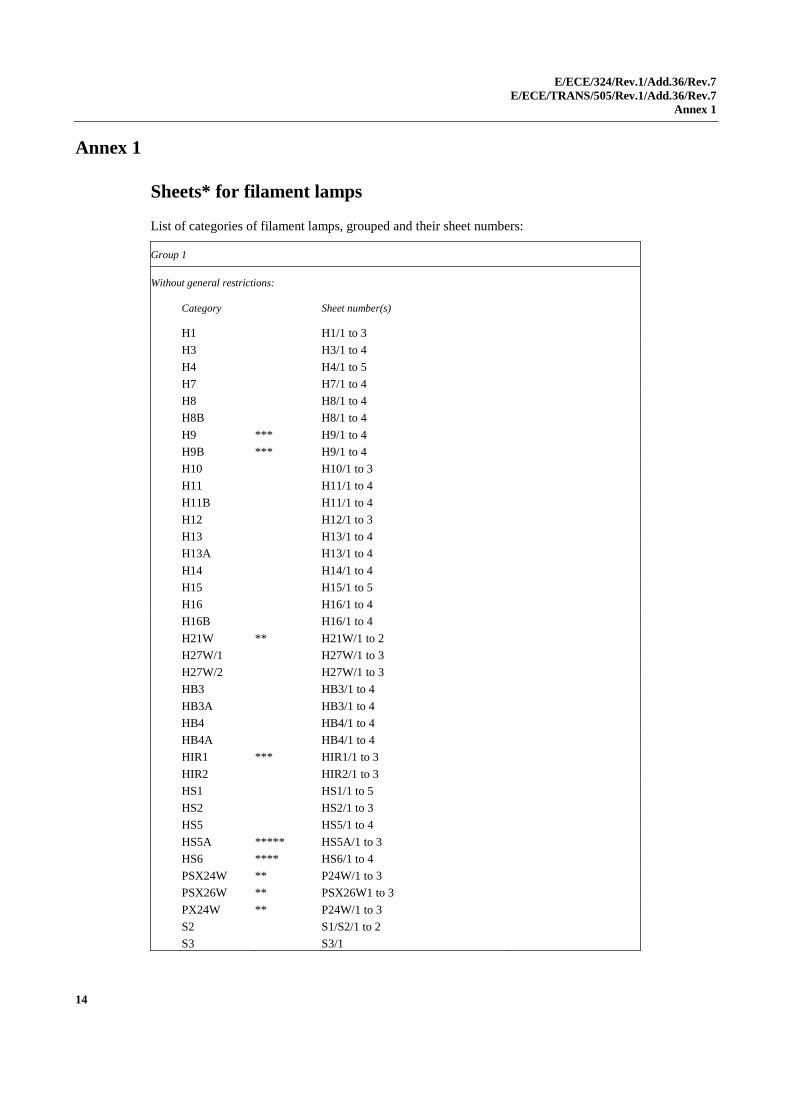
Annex 1
Sheets* for filament lamps
List of categories of filament lamps, grouped and their sheet numbers:
Group 1
Without general restrictions:
Category
Sheet number(s)
H1 H1/1 to 3
H3 H3/1 to 4
H4 H4/1 to 5
H7 H7/1 to 4
H8 H8/1 to 4
H8B H8/1 to 4
H9 *** H9/1 to 4
H9B *** H9/1 to 4
H10 H10/1 to 3
H11 H11/1 to 4
H11B H11/1 to 4
H12 H12/1 to 3
H13 H13/1 to 4
H13A H13/1 to 4
H14 H14/1 to 4
H15 H15/1 to 5
H16 H16/1 to 4
H16B H16/1 to 4
H21W ** H21W/1 to 2
H27W/1 H27W/1 to 3
H27W/2 H27W/1 to 3
HB3 HB3/1 to 4
HB3A HB3/1 to 4
HB4 HB4/1 to 4
HB4A HB4/1 to 4
HIR1 *** HIR1/1 to 3
HIR2 HIR2/1 to 3
HS1 HS1/1 to 5
HS2 HS2/1 to 3
HS5 HS5/1 to 4
HS5A ***** HS5A/1 to 3
HS6 **** HS6/1 to 4
PSX24W ** P24W/1 to 3
PSX26W ** PSX26W1 to 3
PX24W ** P24W/1 to 3
S2 S1/S2/1 to 2
S3 S3/1
E/ECE/324/Rev.1/Add.36/Rev.7
E/ECE/TRANS/505/Rev.1/Add.36/Rev.7
Annex 1
15
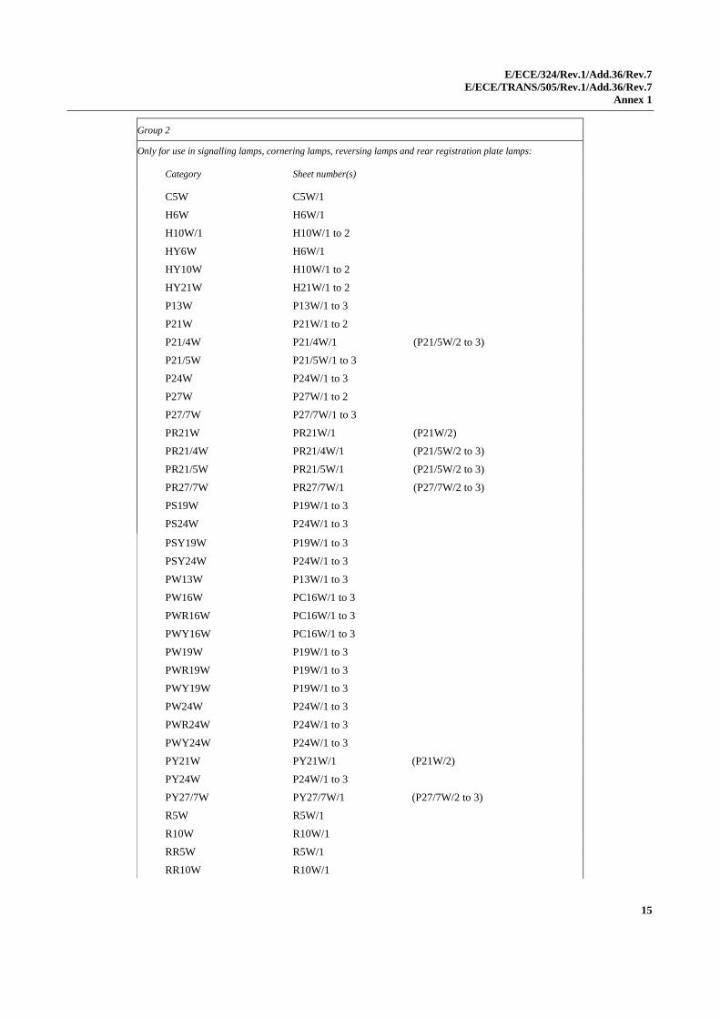
Group 2
Only for use in signalling lamps, cornering lamps, reversing lamps and rear registration plate lamps:
Category
Sheet number(s)
C5W C5W/1
H6W H6W/1
H10W/1 H10W/1 to 2
HY6W H6W/1
HY10W H10W/1 to 2
HY21W H21W/1 to 2
P13W P13W/1 to 3
P21W P21W/1 to 2
P21/4W P21/4W/1 (P21/5W/2 to 3)
P21/5W P21/5W/1 to 3
P24W P24W/1 to 3
P27W P27W/1 to 2
P27/7W P27/7W/1 to 3
PR21W PR21W/1 (P21W/2)
PR21/4W PR21/4W/1 (P21/5W/2 to 3)
PR21/5W PR21/5W/1 (P21/5W/2 to 3)
PR27/7W PR27/7W/1 (P27/7W/2 to 3)
PS19W P19W/1 to 3
PS24W P24W/1 to 3
PSY19W P19W/1 to 3
PSY24W P24W/1 to 3
PW13W P13W/1 to 3
PW16W PC16W/1 to 3
PWR16W PC16W/1 to 3
PWY16W PC16W/1 to 3
PW19W P19W/1 to 3
PWR19W P19W/1 to 3
PWY19W P19W/1 to 3
PW24W P24W/1 to 3
PWR24W P24W/1 to 3
PWY24W P24W/1 to 3
PY21W PY21W/1 (P21W/2)
PY24W P24W/1 to 3
PY27/7W PY27/7W/1 (P27/7W/2 to 3)
R5W R5W/1
R10W R10W/1
RR5W R5W/1
RR10W R10W/1
E/ECE/324/Rev.1/Add.36/Rev.7
E/ECE/TRANS/505/Rev.1/Add.36/Rev.7
Annex 1
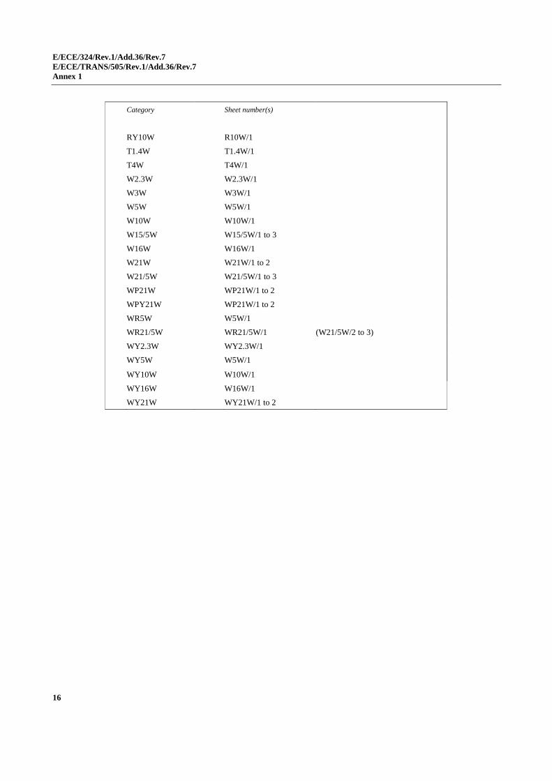
16
Category Sheet number(s)
RY10W R10W/1
T1.4W T1.4W/1
T4W T4W/1
W2.3W W2.3W/1
W3W W3W/1
W5W W5W/1
W10W W10W/1
W15/5W W15/5W/1 to 3
W16W W16W/1
W21W W21W/1 to 2
W21/5W W21/5W/1 to 3
WP21W WP21W/1 to 2
WPY21W WP21W/1 to 2
WR5W W5W/1
WR21/5W WR21/5W/1 (W21/5W/2 to 3)
WY2.3W WY2.3W/1
WY5W W5W/1
WY10W W10W/1
WY16W W16W/1
WY21W WY21W/1 to 2
E/ECE/324/Rev.1/Add.36/Rev.7
E/ECE/TRANS/505/Rev.1/Add.36/Rev.7
Annex 1
17
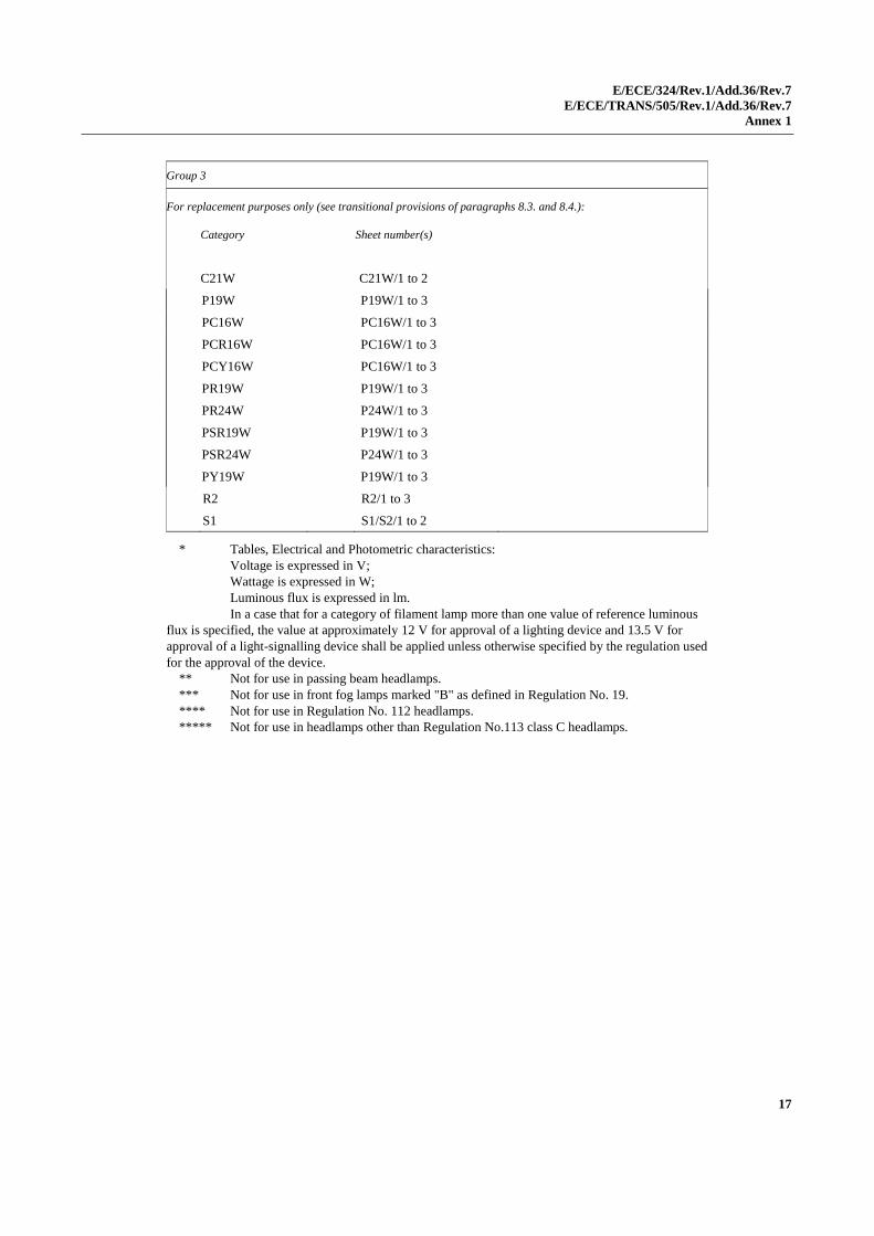
Group 3
For replacement purposes only (see transitional provisions of paragraphs 8.3. and 8.4.):
Category
Sheet number(s)
C21W C21W/1 to 2
P19W P19W/1 to 3
PC16W PC16W/1 to 3
PCR16W PC16W/1 to 3
PCY16W PC16W/1 to 3
PR19W P19W/1 to 3
PR24W P24W/1 to 3
PSR19W P19W/1 to 3
PSR24W P24W/1 to 3
PY19W P19W/1 to 3
R2 R2/1 to 3
S1 S1/S2/1 to 2
* Tables, Electrical and Photometric characteristics:
Voltage is expressed in V;
Wattage is expressed in W;
Luminous flux is expressed in lm.
In a case that for a category of filament lamp more than one value of reference luminous
flux is specified, the value at approximately 12 V for approval of a lighting device and 13.5 V for
approval of a light-signalling device shall be applied unless otherwise specified by the regulation used
for the approval of the device.
** Not for use in passing beam headlamps.
*** Not for use in front fog lamps marked "B" as defined in Regulation No. 19.
**** Not for use in Regulation No. 112 headlamps.
***** Not for use in headlamps other than Regulation No.113 class C headlamps.
E/ECE/324/Rev.1/Add.36/Rev.7
E/ECE/TRANS/505/Rev.1/Add.36/Rev.7
Annex 1
18
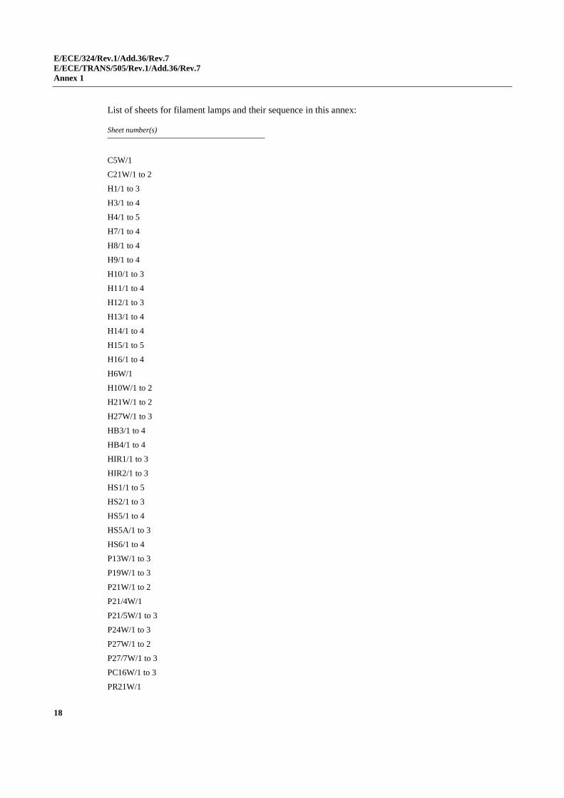
List of sheets for filament lamps and their sequence in this annex:
Sheet number(s)
C5W/1
C21W/1 to 2
H1/1 to 3
H3/1 to 4
H4/1 to 5
H7/1 to 4
H8/1 to 4
H9/1 to 4
H10/1 to 3
H11/1 to 4
H12/1 to 3
H13/1 to 4
H14/1 to 4
H15/1 to 5
H16/1 to 4
H6W/1
H10W/1 to 2
H21W/1 to 2
H27W/1 to 3
HB3/1 to 4
HB4/1 to 4
HIR1/1 to 3
HIR2/1 to 3
HS1/1 to 5
HS2/1 to 3
HS5/1 to 4
HS5A/1 to 3
HS6/1 to 4
P13W/1 to 3
P19W/1 to 3
P21W/1 to 2
P21/4W/1
P21/5W/1 to 3
P24W/1 to 3
P27W/1 to 2
P27/7W/1 to 3
PC16W/1 to 3
PR21W/1
E/ECE/324/Rev.1/Add.36/Rev.7
E/ECE/TRANS/505/Rev.1/Add.36/Rev.7
Annex 1
19
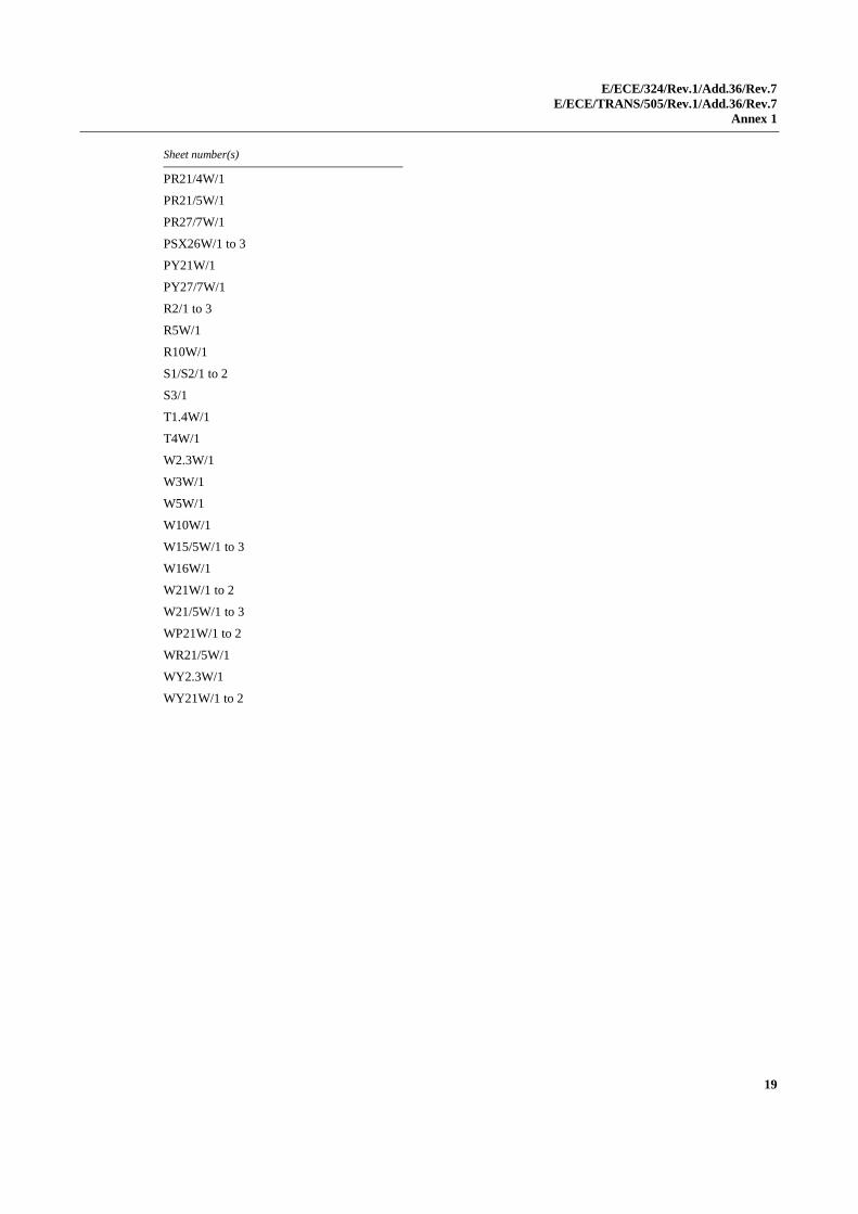
Sheet number(s)
PR21/4W/1
PR21/5W/1
PR27/7W/1
PSX26W/1 to 3
PY21W/1
PY27/7W/1
R2/1 to 3
R5W/1
R10W/1
S1/S2/1 to 2
S3/1
T1.4W/1
T4W/1
W2.3W/1
W3W/1
W5W/1
W10W/1
W15/5W/1 to 3
W16W/1
W21W/1 to 2
W21/5W/1 to 3
WP21W/1 to 2
WR21/5W/1
WY2.3W/1
WY21W/1 to 2
E/ECE/324/Rev.1/Add.36/Rev.7
E/ECE/TRANS/505/Rev.1/Add.36/Rev.7
Annex 1
20
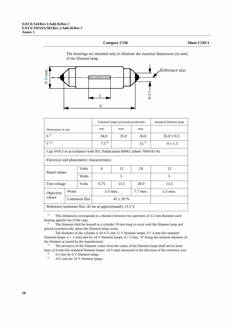
Category C5W Sheet C5W/1
The drawings are intended only to illustrate the essential dimensions (in mm)
of the filament lamp
Dimensions in mm
Filament lamps of normal production Standard filament lamp
min. nom. max.
b 1/
34.0 35.0 36.0 35.0 0.5
f 2/,3/
7.5 4/ 15
5/ 9 1.5
Cap SV8.5 in accordance with IEC Publication 60061 (sheet 7004-81-4)
Electrical and photometric characteristics
Rated values Volts 6 12 24 12
Watts 5 5
Test voltage Volts 6.75 13.5 28.0 13.5
Objective values
Watts 5.5 max. 7.7 max. 5.5 max.
Luminous flux 45 20 %
Reference luminous flux: 45 lm at approximately 13.5 V
1/ This dimension corresponds to a distance between two apertures of 3.5 mm diameter each
bearing against one of the caps. 2/ The filament shall be housed in a cylinder 19 mm long co-axial with the filament lamp and
placed symmetrically about the filament lamp centre.
The diameter of the cylinder is for 6 V and 12 V filament lamps: d + 4 mm (for standard
filament lamps: d + 2 mm) and for 24 V filament lamps: d + 5 mm, "d" being the nominal diameter of
the filament as stated by the manufacturer. 3/ The deviation of the filament centre from the centre of the filament lamp shall not be more
than ±2.0 mm (for standard filament lamps: ±0.5 mm) measured in the direction of the reference axis. 4/ 4.5 mm for 6 V filament lamps. 5/ 16.5 mm for 24 V filament lamps.
E/ECE/324/Rev.1/Add.36/Rev.7
E/ECE/TRANS/505/Rev.1/Add.36/Rev.7
Annex 1
21
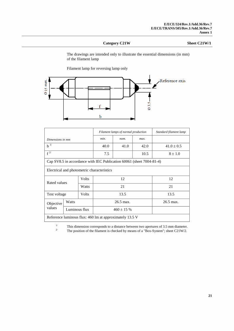
Category C21W Sheet C21W/1
The drawings are intended only to illustrate the essential dimensions (in mm)
of the filament lamp
Filament lamp for reversing lamp only
Dimensions in mm
Filament lamps of normal production Standard filament lamp
min. nom. max.
b 1/
40.0 41.0 42.0 41.0 0.5
f 2/
7.5 10.5 8 1.0
Cap SV8.5 in accordance with IEC Publication 60061 (sheet 7004-81-4)
Electrical and photometric characteristics
Rated values Volts 12 12
Watts 21 21
Test voltage Volts 13.5 13.5
Objective values
Watts 26.5 max. 26.5 max.
Luminous flux 460 15 %
Reference luminous flux: 460 lm at approximately 13.5 V
1/ This dimension corresponds to a distance between two apertures of 3.5 mm diameter.
2/ The position of the filament is checked by means of a "Box-System"; sheet C21W/2.
E/ECE/324/Rev.1/Add.36/Rev.7
E/ECE/TRANS/505/Rev.1/Add.36/Rev.7
Annex 1
22
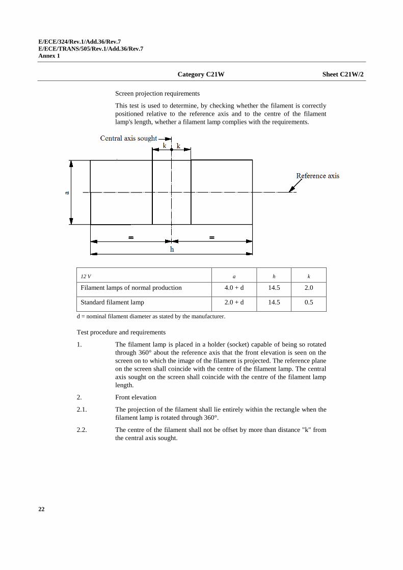
Category C21W Sheet C21W/2
Screen projection requirements
This test is used to determine, by checking whether the filament is correctly
positioned relative to the reference axis and to the centre of the filament
lamp's length, whether a filament lamp complies with the requirements.
12 V a h k
Filament lamps of normal production 4.0 + d 14.5 2.0
Standard filament lamp 2.0 + d 14.5 0.5
d = nominal filament diameter as stated by the manufacturer.
Test procedure and requirements
1. The filament lamp is placed in a holder (socket) capable of being so rotated
through 360° about the reference axis that the front elevation is seen on the
screen on to which the image of the filament is projected. The reference plane
on the screen shall coincide with the centre of the filament lamp. The central
axis sought on the screen shall coincide with the centre of the filament lamp
length.
2. Front elevation
2.1. The projection of the filament shall lie entirely within the rectangle when the
filament lamp is rotated through 360°.
2.2. The centre of the filament shall not be offset by more than distance "k" from
the central axis sought.
E/ECE/324/Rev.1/Add.36/Rev.7
E/ECE/TRANS/505/Rev.1/Add.36/Rev.7
Annex 1
23
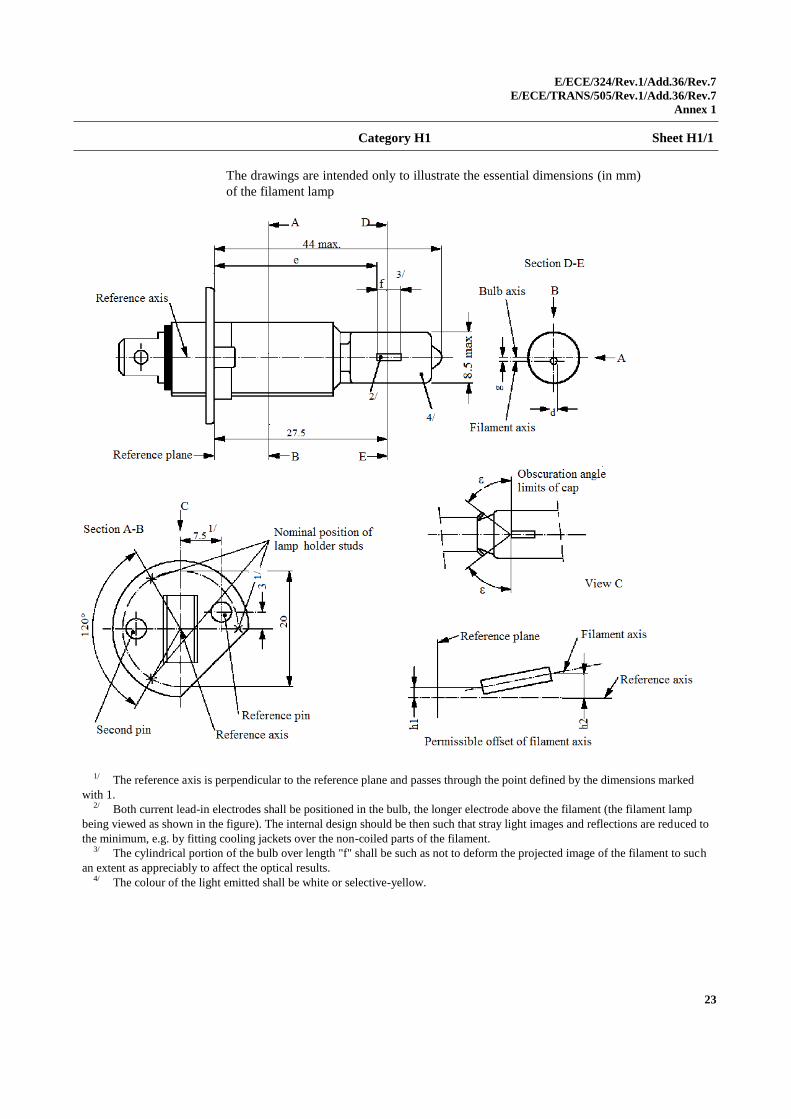
Category H1 Sheet H1/1
The drawings are intended only to illustrate the essential dimensions (in mm)
of the filament lamp
1/ The reference axis is perpendicular to the reference plane and passes through the point defined by the dimensions marked
with 1. 2/ Both current lead-in electrodes shall be positioned in the bulb, the longer electrode above the filament (the filament lamp
being viewed as shown in the figure). The internal design should be then such that stray light images and reflections are reduced to
the minimum, e.g. by fitting cooling jackets over the non-coiled parts of the filament. 3/ The cylindrical portion of the bulb over length "f" shall be such as not to deform the projected image of the filament to such
an extent as appreciably to affect the optical results. 4/ The colour of the light emitted shall be white or selective-yellow.
E/ECE/324/Rev.1/Add.36/Rev.7
E/ECE/TRANS/505/Rev.1/Add.36/Rev.7
Annex 1
24
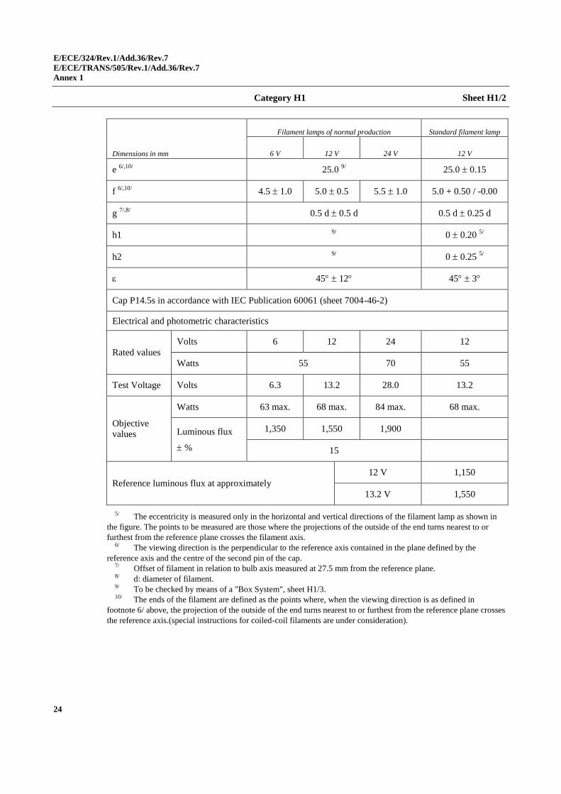
Category H1 Sheet H1/2
Dimensions in mm
Filament lamps of normal production Standard filament lamp
6 V 12 V 24 V 12 V
e 6/,10/
25.0 9/ 25.0 0.15
f 6/,10/
4.5 1.0 5.0 0.5 5.5 1.0 5.0 + 0.50 / -0.00
g 7/,8/
0.5 d 0.5 d 0.5 d 0.25 d
h1 9/
0 0.20 5/
h2 9/
0 0.25 5/
45 12 45 3
Cap P14.5s in accordance with IEC Publication 60061 (sheet 7004-46-2)
Electrical and photometric characteristics
Rated values
Volts 6 12 24 12
Watts 55 70 55
Test Voltage Volts 6.3 13.2 28.0 13.2
Objective values
Watts 63 max. 68 max. 84 max. 68 max.
Luminous flux
%
1,350 1,550 1,900
15
Reference luminous flux at approximately
12 V 1,150
13.2 V 1,550
5/ The eccentricity is measured only in the horizontal and vertical directions of the filament lamp as shown in
the figure. The points to be measured are those where the projections of the outside of the end turns nearest to or
furthest from the reference plane crosses the filament axis. 6/ The viewing direction is the perpendicular to the reference axis contained in the plane defined by the
reference axis and the centre of the second pin of the cap. 7/ Offset of filament in relation to bulb axis measured at 27.5 mm from the reference plane. 8/ d: diameter of filament. 9/ To be checked by means of a "Box System", sheet H1/3. 10/ The ends of the filament are defined as the points where, when the viewing direction is as defined in
footnote 6/ above, the projection of the outside of the end turns nearest to or furthest from the reference plane crosses
the reference axis.(special instructions for coiled-coil filaments are under consideration).
E/ECE/324/Rev.1/Add.36/Rev.7
E/ECE/TRANS/505/Rev.1/Add.36/Rev.7
Annex 1
25
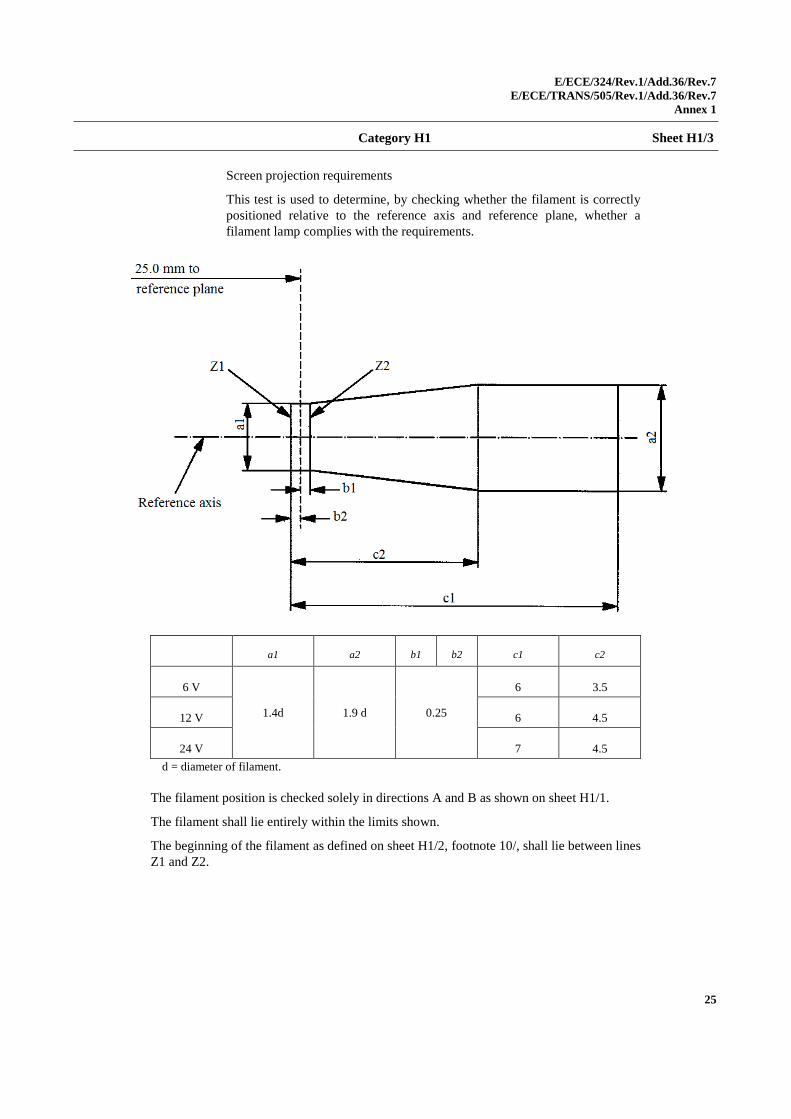
Category H1 Sheet H1/3
Screen projection requirements
This test is used to determine, by checking whether the filament is correctly
positioned relative to the reference axis and reference plane, whether a
filament lamp complies with the requirements.
a1 a2 b1 b2 c1 c2
6 V
1.4d 1.9 d 0.25
6 3.5
12 V 6 4.5
24 V 7 4.5
d = diameter of filament.
The filament position is checked solely in directions A and B as shown on sheet H1/1.
The filament shall lie entirely within the limits shown.
The beginning of the filament as defined on sheet H1/2, footnote 10/, shall lie between lines
Z1 and Z2.
E/ECE/324/Rev.1/Add.36/Rev.7
E/ECE/TRANS/505/Rev.1/Add.36/Rev.7
Annex 1
26
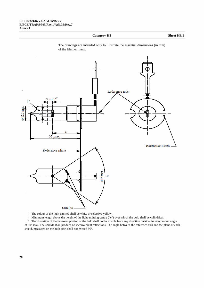
Category H3 Sheet H3/1
The drawings are intended only to illustrate the essential dimensions (in mm)
of the filament lamp
1/ The colour of the light emitted shall be white or selective-yellow. 2/ Minimum length above the height of the light emitting centre ("e") over which the bulb shall be cylindrical. 3/ The distortion of the base-end portion of the bulb shall not be visible from any direction outside the obscuration angle
of 80° max. The shields shall produce no inconvenient reflections. The angle between the reference axis and the plane of each
shield, measured on the bulb side, shall not exceed 90°.
E/ECE/324/Rev.1/Add.36/Rev.7
E/ECE/TRANS/505/Rev.1/Add.36/Rev.7
Annex 1
27
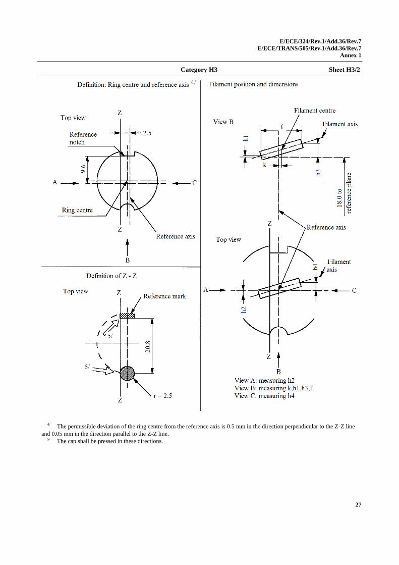
Category H3 Sheet H3/2
4/ The permissible deviation of the ring centre from the reference axis is 0.5 mm in the direction perpendicular to the Z-Z line
and 0.05 mm in the direction parallel to the Z-Z line. 5/ The cap shall be pressed in these directions.
E/ECE/324/Rev.1/Add.36/Rev.7
E/ECE/TRANS/505/Rev.1/Add.36/Rev.7
Annex 1
28
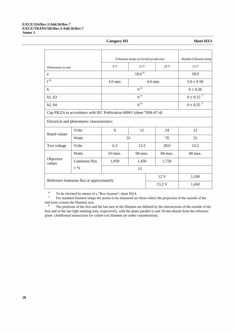
Category H3 Sheet H3/3
Dimensions in mm
Filaments lamps of normal production Standard filament lamp
6 V 12 V 24 V 12 V
e 18.0 6/ 18.0
f 8/
3.0 min. 4.0 min. 5.0 0.50
k 0 6/
0 0.20
h1, h3 0 6/
0 0.15 7/
h2, h4 0 6/
0 0.25 7/
Cap PK22s in accordance with IEC Publication 60061 (sheet 7004-47-4)
Electrical and photometric characteristics
Rated values Volts 6 12 24 12
Watts 55 70 55
Test voltage Volts 6.3 13.2 28.0 13.2
Objective values
Watts 63 max. 68 max. 84 max. 68 max.
Luminous flux
%
1,050 1,450 1,750
15
Reference luminous flux at approximately 12 V 1,100
13.2 V 1,450
6/ To be checked by means of a "Box-System"; sheet H3/4. 7/ For standard filament lamps the points to be measured are those where the projection of the outside of the
end turns crosses the filament axis. 8/ The positions of the first and the last turn of the filament are defined by the intersections of the outside of the
first and of the last light emitting turn, respectively, with the plane parallel to and 18 mm distant from the reference
plane. (Additional instructions for coiled-coil filament are under consideration).
E/ECE/324/Rev.1/Add.36/Rev.7
E/ECE/TRANS/505/Rev.1/Add.36/Rev.7
Annex 1
29
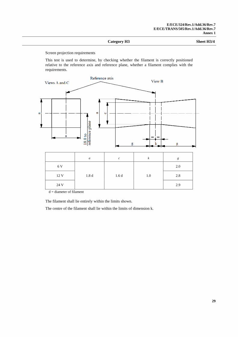
Category H3 Sheet H3/4
Screen projection requirements
This test is used to determine, by checking whether the filament is correctly positioned
relative to the reference axis and reference plane, whether a filament complies with the
requirements.
a c k g
6 V
1.8 d 1.6 d 1.0
2.0
12 V 2.8
24 V 2.9
d = diameter of filament
The filament shall lie entirely within the limits shown.
The centre of the filament shall lie within the limits of dimension k.
E/ECE/324/Rev.1/Add.36/Rev.7
E/ECE/TRANS/505/Rev.1/Add.36/Rev.7
Annex 1
30
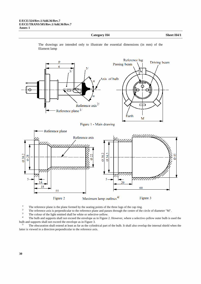
Category H4 Sheet H4/1
The drawings are intended only to illustrate the essential dimensions (in mm) of the
filament lamp
1/ The reference plane is the plane formed by the seating points of the three lugs of the cap ring. 2/ The reference axis is perpendicular to the reference plane and passes through the centre of the circle of diameter "M". 3/ The colour of the light emitted shall be white or selective-yellow. 4/ The bulb and supports shall not exceed the envelope as in Figure 2. However, where a selective-yellow outer bulb is used the
bulb and supports shall not exceed the envelope as in Figure 3. 5/ The obscuration shall extend at least as far as the cylindrical part of the bulb. It shall also overlap the internal shield when the
latter is viewed in a direction perpendicular to the reference axis.
E/ECE/324/Rev.1/Add.36/Rev.7
E/ECE/TRANS/505/Rev.1/Add.36/Rev.7
Annex 1
31
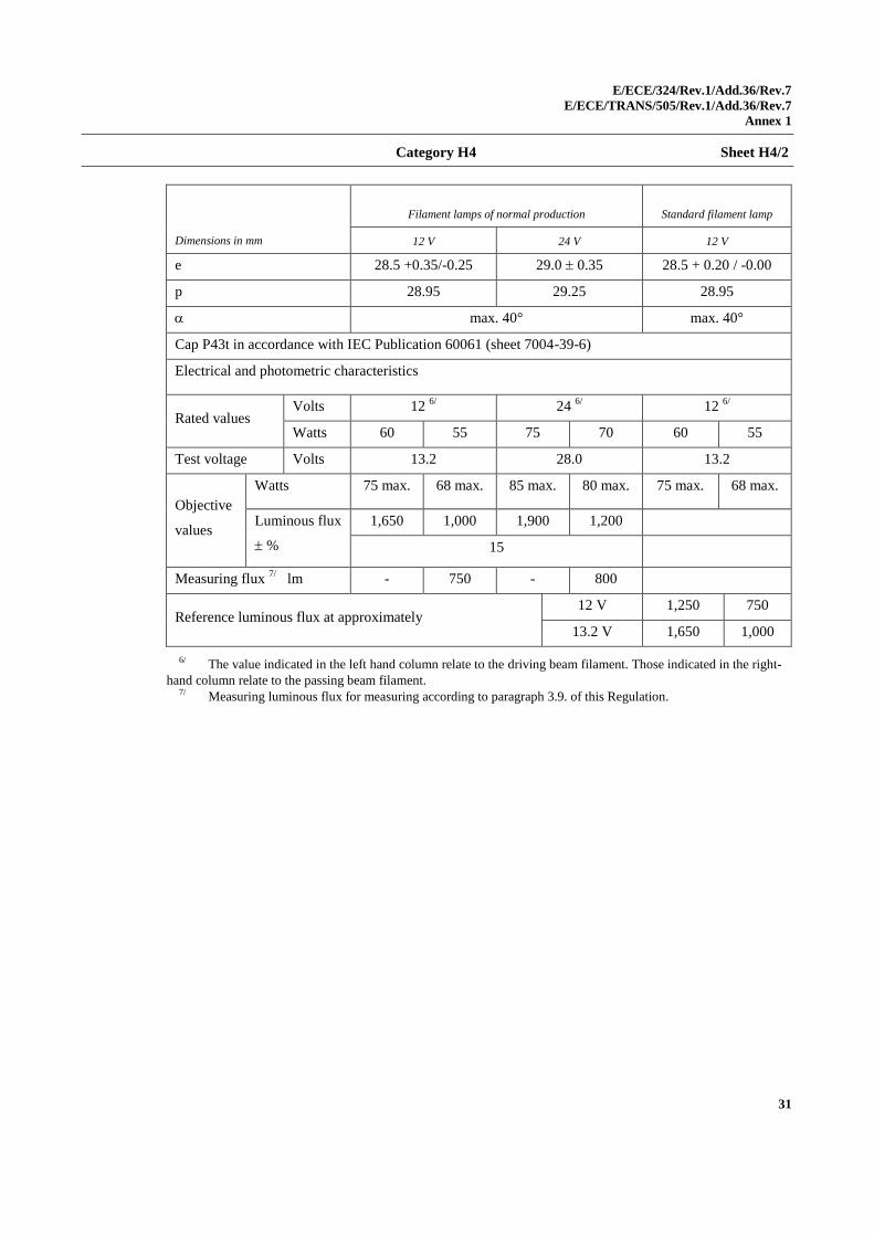
Category H4 Sheet H4/2
Dimensions in mm
Filament lamps of normal production Standard filament lamp
12 V 24 V 12 V
e 28.5 +0.35/-0.25 29.0 0.35 28.5 + 0.20 / -0.00
p 28.95 29.25 28.95
max. 40° max. 40°
Cap P43t in accordance with IEC Publication 60061 (sheet 7004-39-6)
Electrical and photometric characteristics
Rated values Volts 12
6/ 24
6/ 12
6/
Watts 60 55 75 70 60 55
Test voltage Volts 13.2 28.0 13.2
Objective
values
Watts 75 max. 68 max. 85 max. 80 max. 75 max. 68 max.
Luminous flux
%
1,650 1,000 1,900 1,200
15
Measuring flux 7/
lm - 750 - 800
Reference luminous flux at approximately 12 V 1,250 750
13.2 V 1,650 1,000
6/ The value indicated in the left hand column relate to the driving beam filament. Those indicated in the right-
hand column relate to the passing beam filament. 7/ Measuring luminous flux for measuring according to paragraph 3.9. of this Regulation.
E/ECE/324/Rev.1/Add.36/Rev.7
E/ECE/TRANS/505/Rev.1/Add.36/Rev.7
Annex 1
32
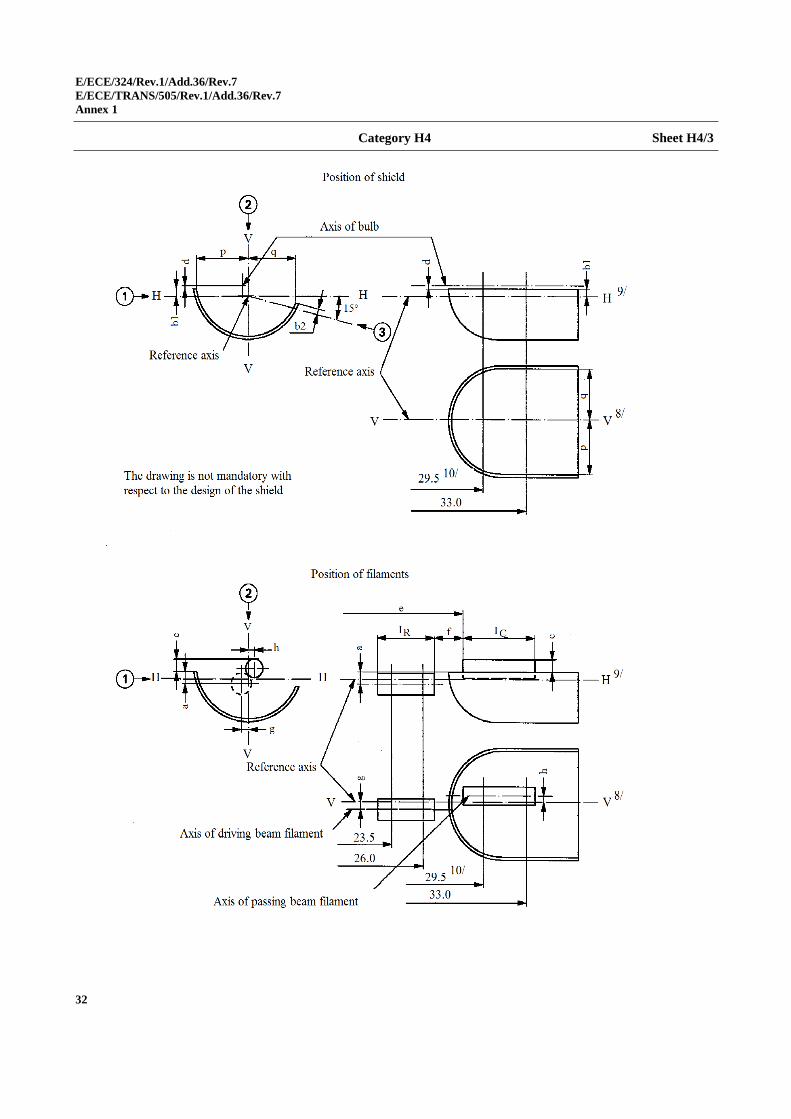
Category H4 Sheet H4/3
E/ECE/324/Rev.1/Add.36/Rev.7
E/ECE/TRANS/505/Rev.1/Add.36/Rev.7
Annex 1
33
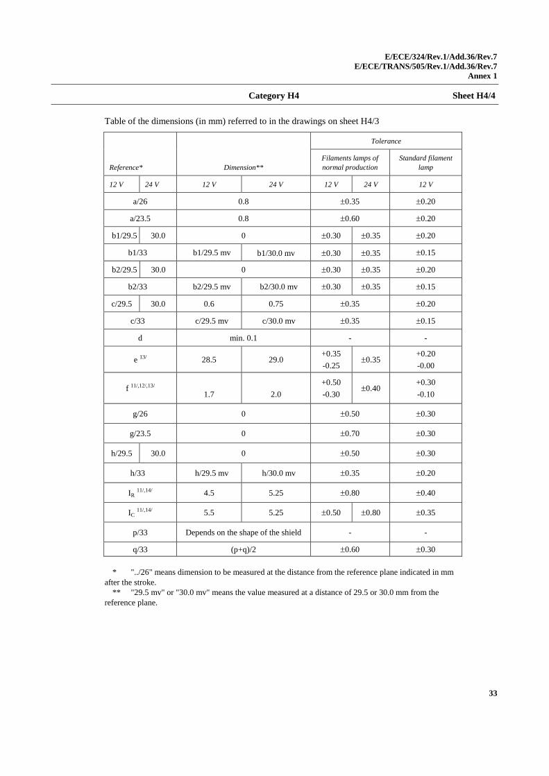
Category H4 Sheet H4/4
Table of the dimensions (in mm) referred to in the drawings on sheet H4/3
Reference* Dimension**
Tolerance
Filaments lamps of
normal production
Standard filament
lamp
12 V 24 V 12 V 24 V 12 V 24 V 12 V
a/26 0.8 0.35 0.20
a/23.5 0.8 0.60 0.20
b1/29.5 30.0 0 0.30 0.35 0.20
b1/33 b1/29.5 mv b1/30.0 mv 0.30 0.35 0.15
b2/29.5 30.0 0 0.30 0.35 0.20
b2/33 b2/29.5 mv b2/30.0 mv 0.30 0.35 0.15
c/29.5 30.0 0.6 0.75 0.35 0.20
c/33 c/29.5 mv c/30.0 mv 0.35 0.15
d min. 0.1 - -
e 13/ 28.5 29.0 +0.35
-0.25 0.35
+0.20
-0.00
f 11/,12/,13/
1.7
2.0
+0.50
-0.30 0.40
+0.30
-0.10
g/26 0 0.50 0.30
g/23.5 0 0.70 0.30
h/29.5 30.0 0 0.50 0.30
h/33 h/29.5 mv h/30.0 mv 0.35 0.20
IR 11/,14/ 4.5 5.25 0.80 0.40
IC 11/,14/ 5.5 5.25 0.50 0.80 0.35
p/33 Depends on the shape of the shield - -
q/33 (p+q)/2 0.60 0.30
* "../26" means dimension to be measured at the distance from the reference plane indicated in mm
after the stroke.
** "29.5 mv" or "30.0 mv" means the value measured at a distance of 29.5 or 30.0 mm from the
reference plane.
E/ECE/324/Rev.1/Add.36/Rev.7
E/ECE/TRANS/505/Rev.1/Add.36/Rev.7
Annex 1
34
Category H4 Sheet H4/5
8/ Plane V-V is the plane perpendicular to the reference plane and passing through the reference axis and
through the intersection of the circle of diameter "M" with the axis of the reference lug. 9/ Plane H-H is the plane perpendicular to both the reference plane and plane V-V and passing through
the reference axis. 10/ 30.0 mm for the 24-Volt type. 11/ The end turns of the filament are defined as being the first luminous turn and the last luminous turn
that are at substantially the correct helix angle. For coiled-coil filaments, the turns are defined by the envelope
of the primary coil. 12/ For the passing beam filament, the points to be measured are the intersections, seen in direction 1, of the
lateral edge of the shield with the outside of the end turns defined under footnote 11/. 13/ "e" denotes the distance from the reference plane to the beginning of the passing beam filament as
defined above. 14/ For the driving beam filament the points to be measured are the intersections, seen in direction 1, of a plane,
parallel to plane H-H and situated at a distance of 0.8 mm below it, with the end turns defined under footnote 11/.
Additional explanations to sheet H4/3
The dimensions below are measured in three directions:
1 For dimensions a, b1, c, d, e, f, IR and IC;
2 For dimensions g, h, p and q;
3 For dimension b2.
Dimensions p and q are measured in planes parallel to and 33 mm away from
the reference plane.
Dimensions b1, b2, c and h are measured in planes parallel to and 29.5 mm
(30.0 mm for 24 V filament lamps) and 33 mm away from the reference
plane.
Dimensions a and g are measured in planes parallel to and 26.0 mm and
23.5 mm away from the reference plane.
Note: For the method of measurement, see Appendix E of IEC Publication 60809.
E/ECE/324/Rev.1/Add.36/Rev.7
E/ECE/TRANS/505/Rev.1/Add.36/Rev.7
Annex 1
35
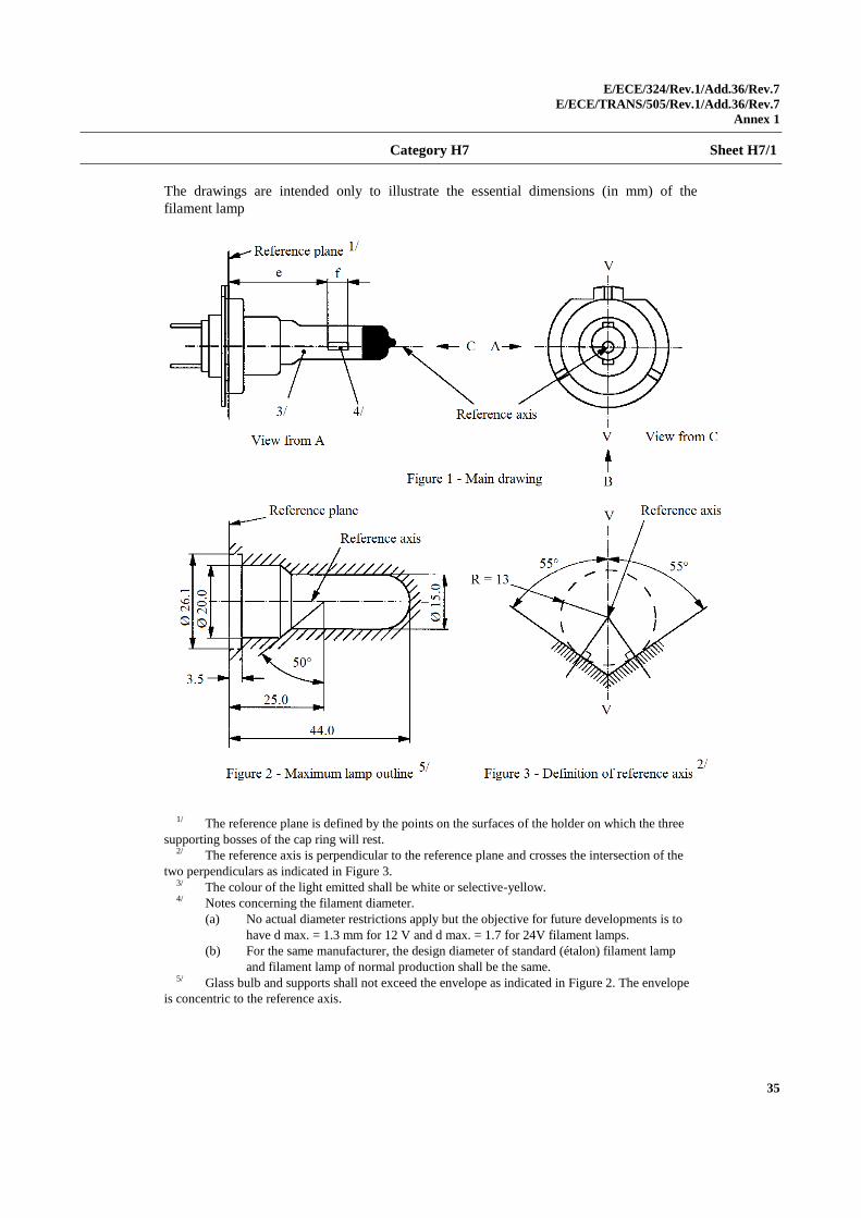
Category H7 Sheet H7/1
The drawings are intended only to illustrate the essential dimensions (in mm) of the
filament lamp
1/ The reference plane is defined by the points on the surfaces of the holder on which the three
supporting bosses of the cap ring will rest. 2/ The reference axis is perpendicular to the reference plane and crosses the intersection of the
two perpendiculars as indicated in Figure 3. 3/ The colour of the light emitted shall be white or selective-yellow. 4/ Notes concerning the filament diameter.
(a) No actual diameter restrictions apply but the objective for future developments is to
have d max. = 1.3 mm for 12 V and d max. = 1.7 for 24V filament lamps.
(b) For the same manufacturer, the design diameter of standard (étalon) filament lamp
and filament lamp of normal production shall be the same. 5/ Glass bulb and supports shall not exceed the envelope as indicated in Figure 2. The envelope
is concentric to the reference axis.
E/ECE/324/Rev.1/Add.36/Rev.7
E/ECE/TRANS/505/Rev.1/Add.36/Rev.7
Annex 1
36
Category H7 Sheet H7/2
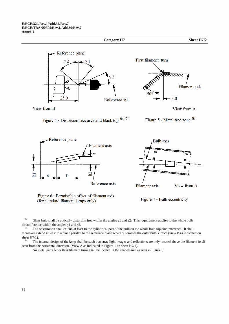
6/ Glass bulb shall be optically distortion free within the angles 1 and 2. This requirement applies to the whole bulb
circumference within the angles 1 and 2. 7/ The obscuration shall extend at least to the cylindrical part of the bulb on the whole bulb top circumference. It shall
moreover extend at least to a plane parallel to the reference plane where 3 crosses the outer bulb surface (view B as indicated on
sheet H7/1). 8/ The internal design of the lamp shall be such that stray light images and reflections are only located above the filament itself
seen from the horizontal direction. (View A as indicated in Figure 1 on sheet H7/1).
No metal parts other than filament turns shall be located in the shaded area as seen in Figure 5.
E/ECE/324/Rev.1/Add.36/Rev.7
E/ECE/TRANS/505/Rev.1/Add.36/Rev.7
Annex 1
37
Category H7 Sheet H7/3
Dimensions in mm
Filaments lamps of normal production
Standard
filament lamp
12 V 24 V 12 V
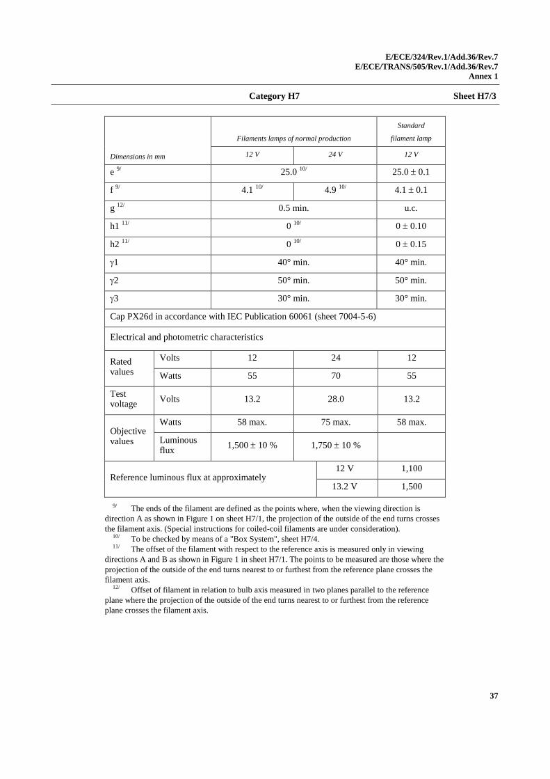
e 9/
25.0 10/
25.0 0.1
f 9/
4.1 10/
4.9 10/
4.1 0.1
g 12/
0.5 min. u.c.
h1 11/
0 10/
0 0.10
h2 11/
0 10/
0 0.15
1 40° min. 40° min.
2 50° min. 50° min.
3 30° min. 30° min.
Cap PX26d in accordance with IEC Publication 60061 (sheet 7004-5-6)
Electrical and photometric characteristics
Rated values
Volts 12 24 12
Watts 55 70 55
Test voltage
Volts 13.2 28.0 13.2
Objectivevalues
Watts 58 max. 75 max. 58 max.
Luminous flux
1,500 10 % 1,750 10 %
Reference luminous flux at approximately 12 V 1,100
13.2 V 1,500
9/ The ends of the filament are defined as the points where, when the viewing direction is
direction A as shown in Figure 1 on sheet H7/1, the projection of the outside of the end turns crosses
the filament axis. (Special instructions for coiled-coil filaments are under consideration). 10/ To be checked by means of a "Box System", sheet H7/4. 11/ The offset of the filament with respect to the reference axis is measured only in viewing
directions A and B as shown in Figure 1 in sheet H7/1. The points to be measured are those where the
projection of the outside of the end turns nearest to or furthest from the reference plane crosses the
filament axis. 12/ Offset of filament in relation to bulb axis measured in two planes parallel to the reference
plane where the projection of the outside of the end turns nearest to or furthest from the reference
plane crosses the filament axis.
E/ECE/324/Rev.1/Add.36/Rev.7
E/ECE/TRANS/505/Rev.1/Add.36/Rev.7
Annex 1
38
Category H7 Sheet H7/4
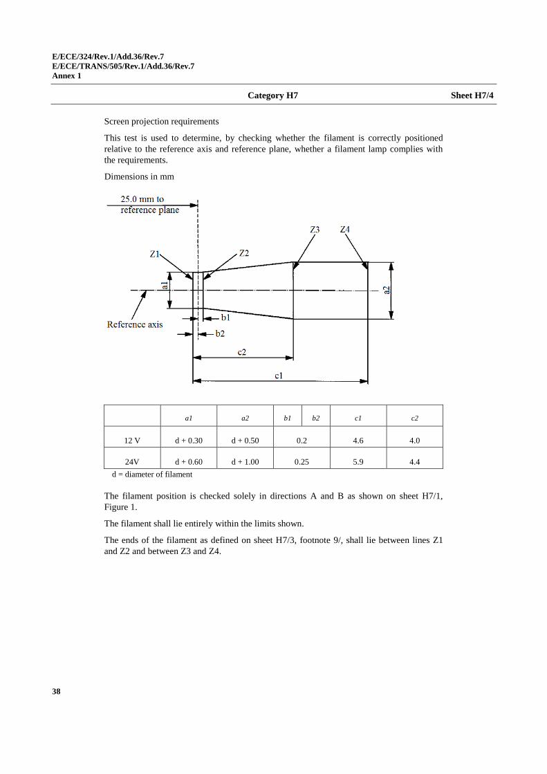
Screen projection requirements
This test is used to determine, by checking whether the filament is correctly positioned
relative to the reference axis and reference plane, whether a filament lamp complies with
the requirements.
Dimensions in mm
a1 a2 b1 b2 c1 c2
12 V d + 0.30 d + 0.50 0.2 4.6 4.0
24V d + 0.60 d + 1.00 0.25 5.9 4.4
d = diameter of filament
The filament position is checked solely in directions A and B as shown on sheet H7/1,
Figure 1.
The filament shall lie entirely within the limits shown.
The ends of the filament as defined on sheet H7/3, footnote 9/, shall lie between lines Z1
and Z2 and between Z3 and Z4.
E/ECE/324/Rev.1/Add.36/Rev.7
E/ECE/TRANS/505/Rev.1/Add.36/Rev.7
Annex 1
39
Categories H8 and H8B Sheet H8/1
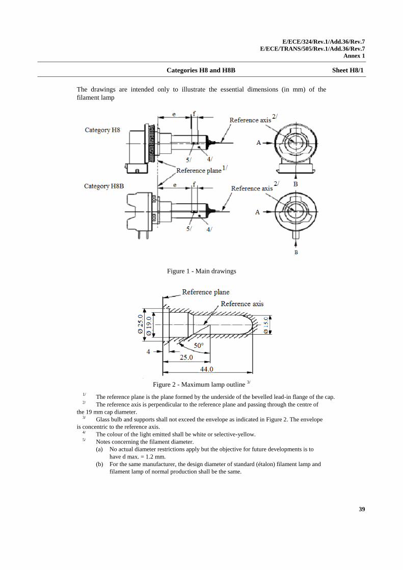
The drawings are intended only to illustrate the essential dimensions (in mm) of the
filament lamp
Figure 1 - Main drawings
Figure 2 - Maximum lamp outline
3/
1/ The reference plane is the plane formed by the underside of the bevelled lead-in flange of the cap.
2/ The reference axis is perpendicular to the reference plane and passing through the centre of
the 19 mm cap diameter. 3/ Glass bulb and supports shall not exceed the envelope as indicated in Figure 2. The envelope
is concentric to the reference axis. 4/ The colour of the light emitted shall be white or selective-yellow. 5/ Notes concerning the filament diameter.
(a) No actual diameter restrictions apply but the objective for future developments is to
have d max. = 1.2 mm.
(b) For the same manufacturer, the design diameter of standard (étalon) filament lamp and
filament lamp of normal production shall be the same.
E/ECE/324/Rev.1/Add.36/Rev.7
E/ECE/TRANS/505/Rev.1/Add.36/Rev.7
Annex 1
40
Categories H8 and H8B Sheet H8/2
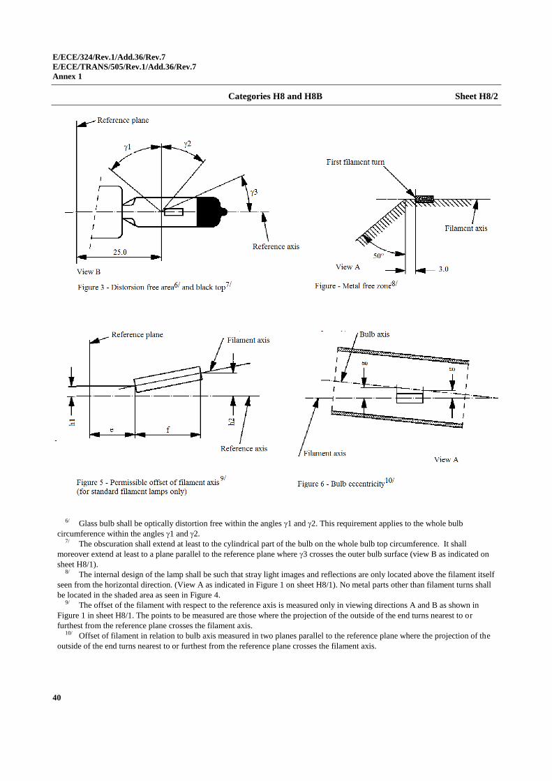
6/ Glass bulb shall be optically distortion free within the angles 1 and 2. This requirement applies to the whole bulb
circumference within the angles 1 and 2. 7/ The obscuration shall extend at least to the cylindrical part of the bulb on the whole bulb top circumference. It shall
moreover extend at least to a plane parallel to the reference plane where 3 crosses the outer bulb surface (view B as indicated on
sheet H8/1). 8/ The internal design of the lamp shall be such that stray light images and reflections are only located above the filament itself
seen from the horizontal direction. (View A as indicated in Figure 1 on sheet H8/1). No metal parts other than filament turns shall
be located in the shaded area as seen in Figure 4. 9/ The offset of the filament with respect to the reference axis is measured only in viewing directions A and B as shown in
Figure 1 in sheet H8/1. The points to be measured are those where the projection of the outside of the end turns nearest to or
furthest from the reference plane crosses the filament axis. 10/ Offset of filament in relation to bulb axis measured in two planes parallel to the reference plane where the projection of the
outside of the end turns nearest to or furthest from the reference plane crosses the filament axis.
E/ECE/324/Rev.1/Add.36/Rev.7
E/ECE/TRANS/505/Rev.1/Add.36/Rev.7
Annex 1
41
Categories H8 and H8B Sheet H8/3
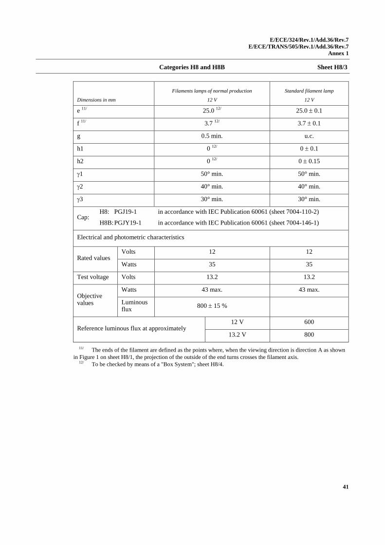
Dimensions in mm
Filaments lamps of normal production
12 V
Standard filament lamp
12 V
e 11/
25.0 12/
25.0 0.1
f 11/
3.7 12/
3.7 0.1
g 0.5 min. u.c.
h1 0 12/
0 0.1
h2 0 12/
0 0.15
1 50° min. 50° min.
2 40° min. 40° min.
3 30° min. 30° min.
Cap: H8: PGJ19-1
H8B: PGJY19-1
in accordance with IEC Publication 60061 (sheet 7004-110-2)
in accordance with IEC Publication 60061 (sheet 7004-146-1)
Electrical and photometric characteristics
Rated values Volts 12 12
Watts 35 35
Test voltage Volts 13.2 13.2
Objective values
Watts 43 max. 43 max.
Luminous flux
800 15 %
Reference luminous flux at approximately 12 V 600
13.2 V 800
11/ The ends of the filament are defined as the points where, when the viewing direction is direction A as shown
in Figure 1 on sheet H8/1, the projection of the outside of the end turns crosses the filament axis. 12/ To be checked by means of a "Box System"; sheet H8/4.
E/ECE/324/Rev.1/Add.36/Rev.7
E/ECE/TRANS/505/Rev.1/Add.36/Rev.7
Annex 1
42
Categories H8 and H8B Sheet H8/4
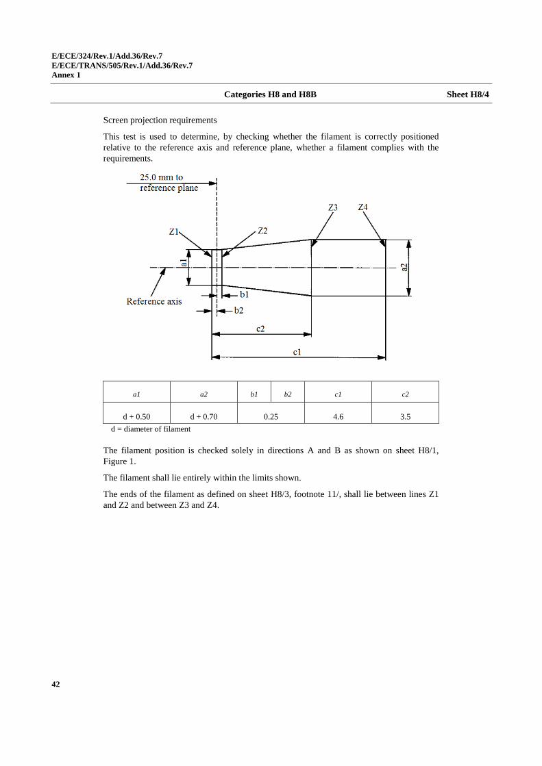
Screen projection requirements
This test is used to determine, by checking whether the filament is correctly positioned
relative to the reference axis and reference plane, whether a filament complies with the
requirements.
a1 a2 b1 b2 c1 c2
d + 0.50 d + 0.70 0.25 4.6 3.5
d = diameter of filament
The filament position is checked solely in directions A and B as shown on sheet H8/1,
Figure 1.
The filament shall lie entirely within the limits shown.
The ends of the filament as defined on sheet H8/3, footnote 11/, shall lie between lines Z1
and Z2 and between Z3 and Z4.
E/ECE/324/Rev.1/Add.36/Rev.7
E/ECE/TRANS/505/Rev.1/Add.36/Rev.7
Annex 1
43
Categories H9 and H9B Sheet H9/1
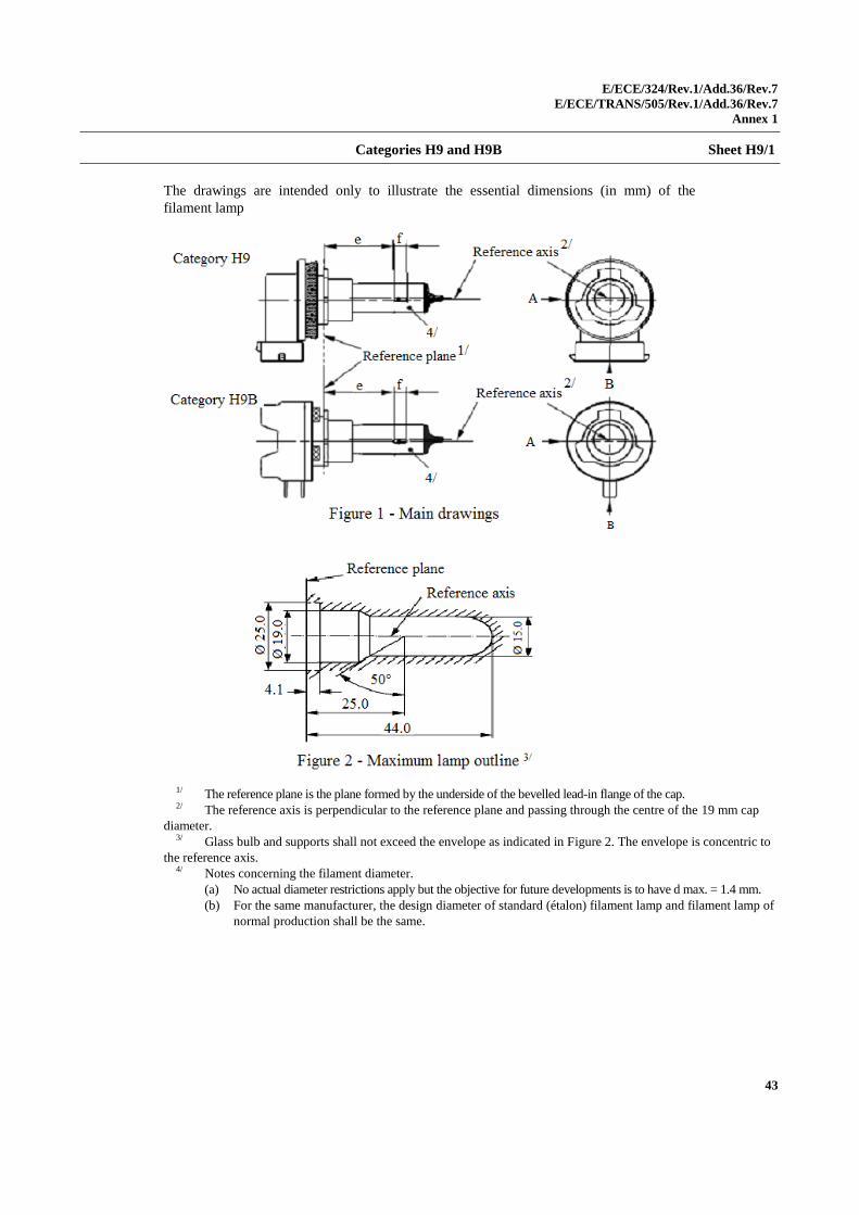
The drawings are intended only to illustrate the essential dimensions (in mm) of the
filament lamp
1/ The reference plane is the plane formed by the underside of the bevelled lead-in flange of the cap. 2/ The reference axis is perpendicular to the reference plane and passing through the centre of the 19 mm cap
diameter. 3/ Glass bulb and supports shall not exceed the envelope as indicated in Figure 2. The envelope is concentric to
the reference axis. 4/ Notes concerning the filament diameter.
(a) No actual diameter restrictions apply but the objective for future developments is to have d max. = 1.4 mm.
(b) For the same manufacturer, the design diameter of standard (étalon) filament lamp and filament lamp of
normal production shall be the same.
E/ECE/324/Rev.1/Add.36/Rev.7
E/ECE/TRANS/505/Rev.1/Add.36/Rev.7
Annex 1
44
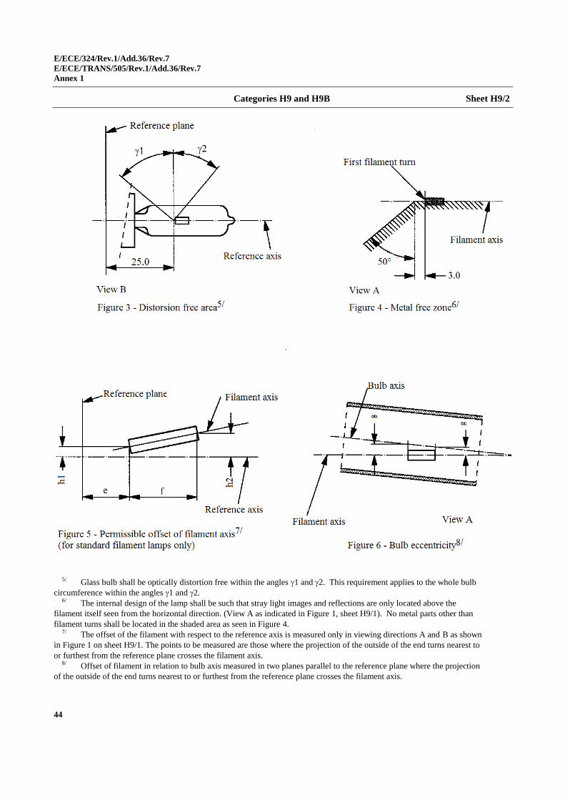
Categories H9 and H9B Sheet H9/2
5/ Glass bulb shall be optically distortion free within the angles 1 and 2. This requirement applies to the whole bulb
circumference within the angles 1 and 2. 6/ The internal design of the lamp shall be such that stray light images and reflections are only located above the
filament itself seen from the horizontal direction. (View A as indicated in Figure 1, sheet H9/1). No metal parts other than
filament turns shall be located in the shaded area as seen in Figure 4. 7/ The offset of the filament with respect to the reference axis is measured only in viewing directions A and B as shown
in Figure 1 on sheet H9/1. The points to be measured are those where the projection of the outside of the end turns nearest to
or furthest from the reference plane crosses the filament axis. 8/ Offset of filament in relation to bulb axis measured in two planes parallel to the reference plane where the projection
of the outside of the end turns nearest to or furthest from the reference plane crosses the filament axis.
E/ECE/324/Rev.1/Add.36/Rev.7
E/ECE/TRANS/505/Rev.1/Add.36/Rev.7
Annex 1
45
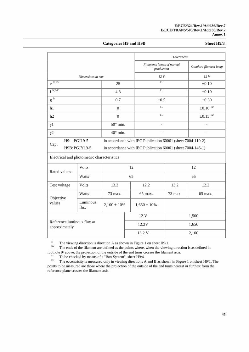
Categories H9 and H9B Sheet H9/3
Dimensions in mm
Tolerances
Filaments lamps of normal
production Standard filament lamp
12 V 12 V
e 9/,10/
25 11/
0.10
f 9/,10/
4.8 11/
0.10
g 9/
0.7 0.5 0.30
h1 0 11/
0.10 12/
h2 0 11/
0.15 12/
1 50° min. - -
2 40° min. - -
Cap: H9: PGJ19-5
H9B: PGJY19-5
in accordance with IEC Publication 60061 (sheet 7004-110-2)
in accordance with IEC Publication 60061 (sheet 7004-146-1)
Electrical and photometric characteristics
Rated values Volts 12 12
Watts 65 65
Test voltage Volts 13.2 12.2 13.2 12.2
Objective
values
Watts 73 max. 65 max. 73 max. 65 max.
Luminous
flux 2,100 10% 1,650 10%
Reference luminous flux at
approximately
12 V 1,500
12.2V 1,650
13.2 V 2,100
9/ The viewing direction is direction A as shown in Figure 1 on sheet H9/1. 10/ The ends of the filament are defined as the points where, when the viewing direction is as defined in
footnote 9/ above, the projection of the outside of the end turns crosses the filament axis. 11/ To be checked by means of a "Box System"; sheet H9/4. 12/ The eccentricity is measured only in viewing directions A and B as shown in Figure 1 on sheet H9/1. The
points to be measured are those where the projection of the outside of the end turns nearest or furthest from the
reference plane crosses the filament axis.
E/ECE/324/Rev.1/Add.36/Rev.7
E/ECE/TRANS/505/Rev.1/Add.36/Rev.7
Annex 1
46
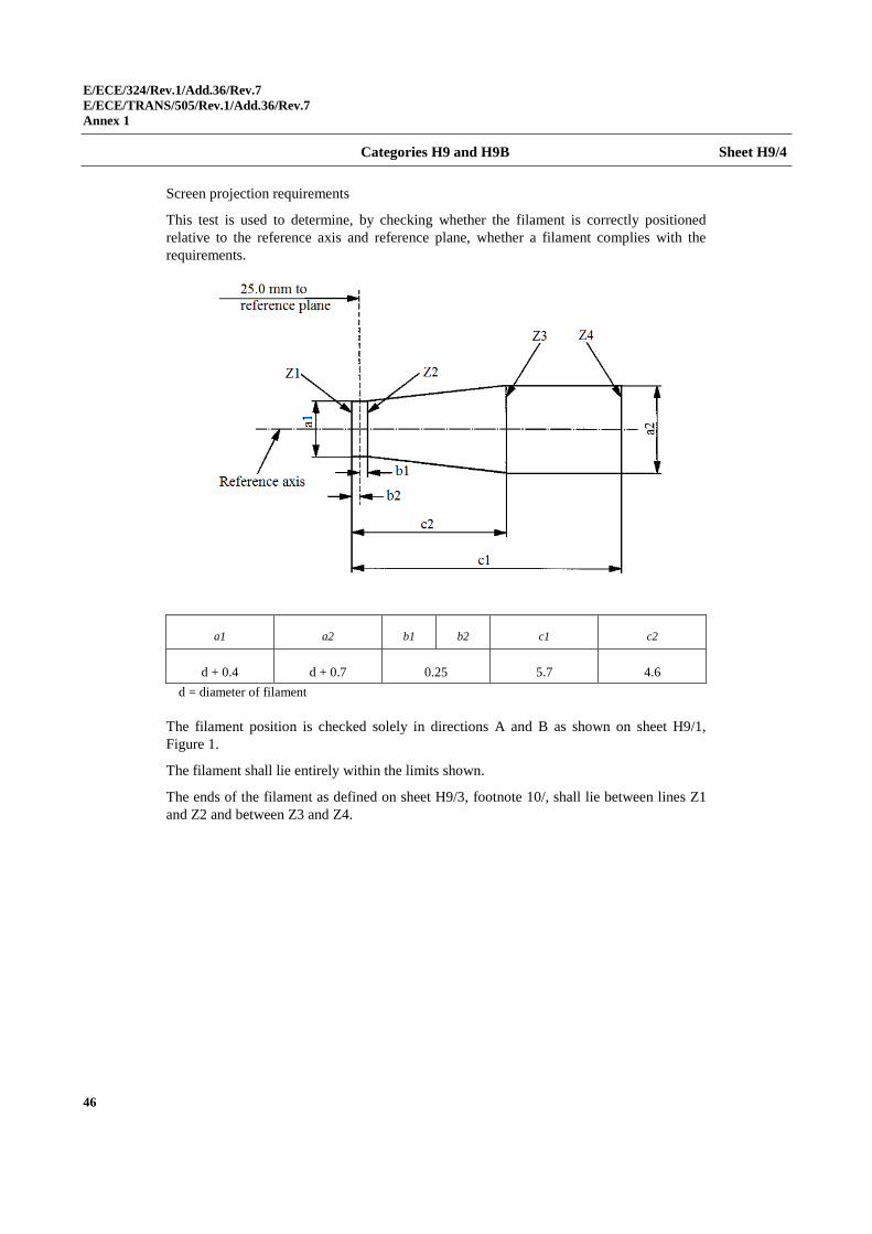
Categories H9 and H9B Sheet H9/4
Screen projection requirements
This test is used to determine, by checking whether the filament is correctly positioned
relative to the reference axis and reference plane, whether a filament complies with the
requirements.
a1 a2 b1 b2 c1 c2
d + 0.4 d + 0.7 0.25 5.7 4.6
d = diameter of filament
The filament position is checked solely in directions A and B as shown on sheet H9/1,
Figure 1.
The filament shall lie entirely within the limits shown.
The ends of the filament as defined on sheet H9/3, footnote 10/, shall lie between lines Z1
and Z2 and between Z3 and Z4.
E/ECE/324/Rev.1/Add.36/Rev.7
E/ECE/TRANS/505/Rev.1/Add.36/Rev.7
Annex 1
47
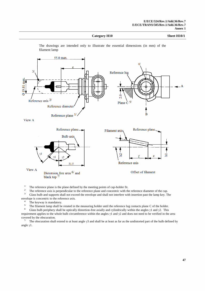
Category H10 Sheet H10/1
The drawings are intended only to illustrate the essential dimensions (in mm) of the
filament lamp
1/ The reference plane is the plane defined by the meeting points of cap-holder fit. 2/ The reference axis is perpendicular to the reference plane and concentric with the reference diameter of the cap. 3/ Glass bulb and supports shall not exceed the envelope and shall not interfere with insertion past the lamp key. The
envelope is concentric to the reference axis. 4/ The keyway is mandatory. 5/ The filament lamp shall be rotated in the measuring holder until the reference lug contacts plane C of the holder. 6/ Glass bulb periphery shall be optically distortion-free axially and cylindrically within the angles 1 and 2. This
requirement applies to the whole bulb circumference within the angles 1 and 2 and does not need to be verified in the area
covered by the obscuration. 7/ The obscuration shall extend to at least angle 3 and shall be at least as far as the undistorted part of the bulb defined by
angle 1.
E/ECE/324/Rev.1/Add.36/Rev.7
E/ECE/TRANS/505/Rev.1/Add.36/Rev.7
Annex 1
48
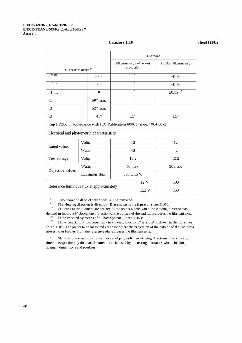
Category H10 Sheet H10/2
Dimensions in mm 8/
Tolerance
Filament lamps of normal
production
Standard filament lamp
e 9/,10/
28.9 11/
0.16
f 9/,10/
5.2 11/
0.16
h1, h2 0 11/
0.15 12/
1 50° min. - -
2 52° min. - -
3 45° 5° 5°
Cap PY20d in accordance with IEC Publication 60061 (sheet 7004-31-2)
Electrical and photometric characteristics
Rated values Volts 12 12
Watts 42 42
Test voltage Volts 13.2 13.2
Objective values Watts 50 max. 50 max.
Luminous flux 850 15 %
Reference luminous flux at approximately 12 V 600
13.2 V 850
8/ Dimensions shall be checked with O-ring removed. 9/ The viewing direction is direction* B as shown in the figure on sheet H10/1. 10/ The ends of the filament are defined as the points where, when the viewing direction* as
defined in footnote 9/ above, the projection of the outside of the end turns crosses the filament axis. 11/ To be checked by means of a "Box-System", sheet H10/3*. 12/ The eccentricity is measured only in viewing directions* A and B as shown in the figure on
sheet H10/1. The points to be measured are those where the projection of the outside of the end turns
nearest to or furthest from the reference plane crosses the filament axis.
* Manufacturers may choose another set of perpendicular viewing directions. The viewing
directions specified by the manufacturer are to be used by the testing laboratory when checking
filament dimensions and position.
E/ECE/324/Rev.1/Add.36/Rev.7
E/ECE/TRANS/505/Rev.1/Add.36/Rev.7
Annex 1
49
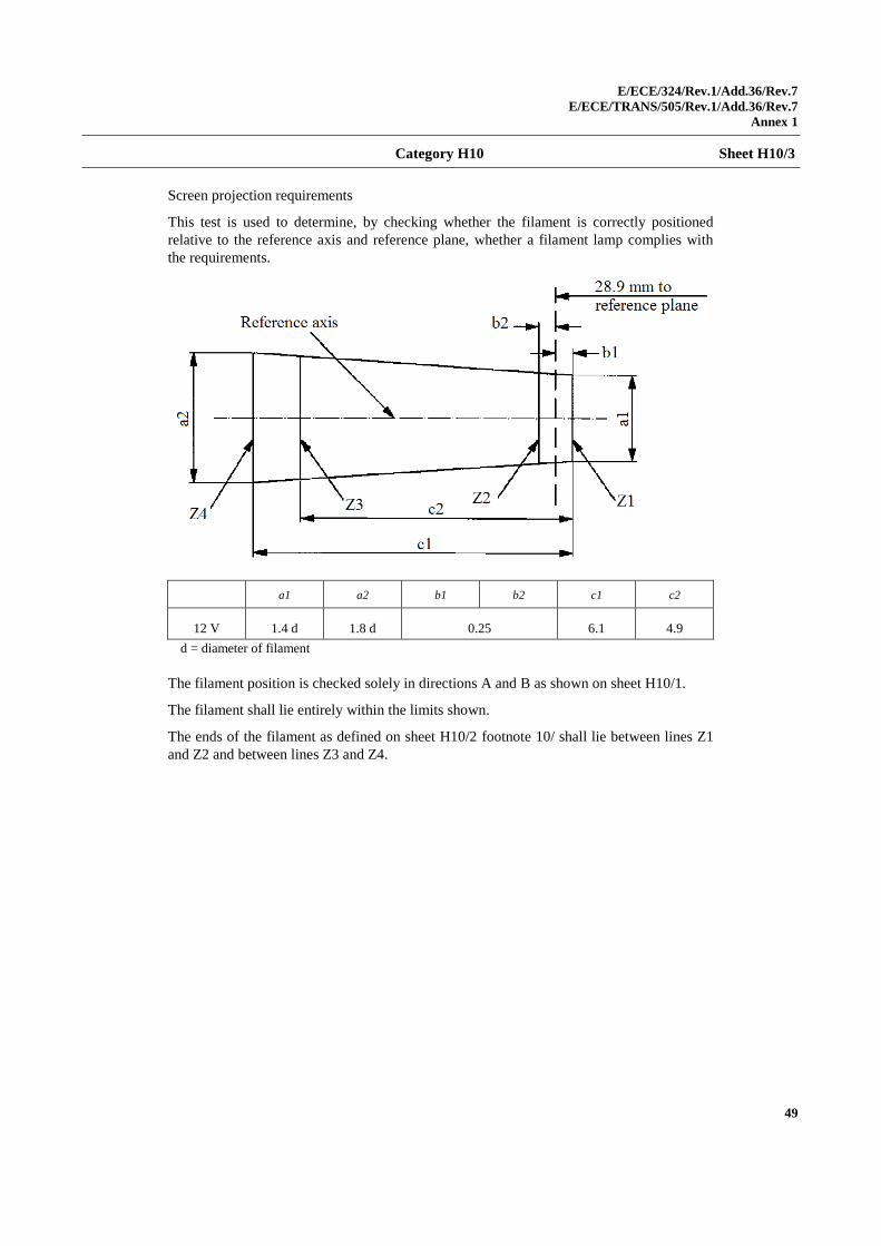
Category H10 Sheet H10/3
Screen projection requirements
This test is used to determine, by checking whether the filament is correctly positioned
relative to the reference axis and reference plane, whether a filament lamp complies with
the requirements.
a1 a2 b1 b2 c1 c2
12 V 1.4 d 1.8 d 0.25 6.1 4.9
d = diameter of filament
The filament position is checked solely in directions A and B as shown on sheet H10/1.
The filament shall lie entirely within the limits shown.
The ends of the filament as defined on sheet H10/2 footnote 10/ shall lie between lines Z1
and Z2 and between lines Z3 and Z4.
E/ECE/324/Rev.1/Add.36/Rev.7
E/ECE/TRANS/505/Rev.1/Add.36/Rev.7
Annex 1
50
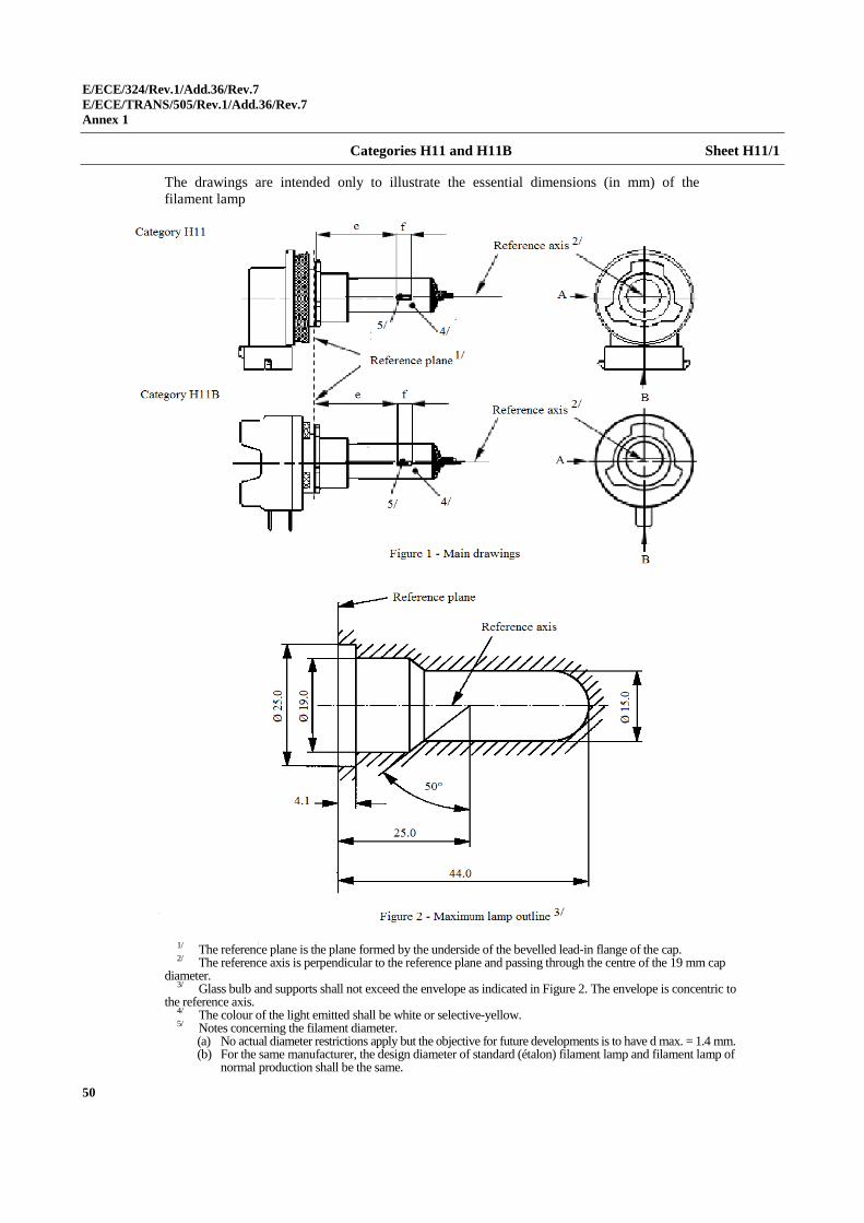
Categories H11 and H11B Sheet H11/1
The drawings are intended only to illustrate the essential dimensions (in mm) of the
filament lamp
1/ The reference plane is the plane formed by the underside of the bevelled lead-in flange of the cap. 2/ The reference axis is perpendicular to the reference plane and passing through the centre of the 19 mm cap
diameter. 3/ Glass bulb and supports shall not exceed the envelope as indicated in Figure 2. The envelope is concentric to
the reference axis. 4/ The colour of the light emitted shall be white or selective-yellow. 5/ Notes concerning the filament diameter.
(a) No actual diameter restrictions apply but the objective for future developments is to have d max. = 1.4 mm. (b) For the same manufacturer, the design diameter of standard (étalon) filament lamp and filament lamp of
normal production shall be the same.
E/ECE/324/Rev.1/Add.36/Rev.7
E/ECE/TRANS/505/Rev.1/Add.36/Rev.7
Annex 1
51
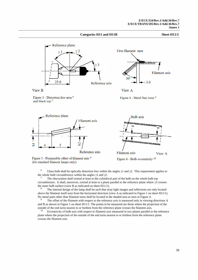
Categories H11 and H11B Sheet H11/2
6/ Glass bulb shall be optically distortion free within the angles 1 and 2. This requirement applies to
the whole bulb circumference within the angles 1 and 2. 7/ The obscuration shall extend at least to the cylindrical part of the bulb on the whole bulb top
circumference. It shall, moreover, extend at least to a plane parallel to the reference plane where 3 crosses
the outer bulb surface (view B as indicated on sheet H11/1). 8/ The internal design of the lamp shall be such that stray light images and reflections are only located
above the filament itself seen from the horizontal direction (view A as indicated in Figure 1 on sheet H11/1).
No metal parts other than filament turns shall be located in the shaded area as seen in Figure 4. 9/ The offset of the filament with respect to the reference axis is measured only in viewing directions A
and B as shown in Figure 1 on sheet H11/1. The points to be measured are those where the projection of the
outside of the end turns nearest to or furthest from the reference plane crosses the filament axis. 10/ Eccentricity of bulb axis with respect to filament axis measured in two planes parallel to the reference
plane where the projection of the outside of the end turns nearest to or furthest from the reference plane
crosses the filament axis.
E/ECE/324/Rev.1/Add.36/Rev.7
E/ECE/TRANS/505/Rev.1/Add.36/Rev.7
Annex 1
52
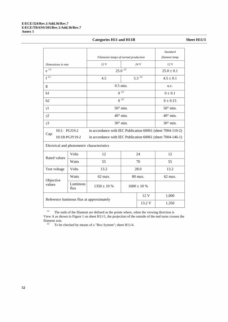
Categories H11 and H11B Sheet H11/3
Dimensions in mm
Filaments lamps of normal production
Standard
filament lamp
12 V 24 V 12 V
e 11/
25.0 12/
25.0 0.1
f 11/
4.5 5.3 12/
4.5 0.1
g 0.5 min. u.c.
h1 0 12/
0 0.1
h2 0 12/
0 0.15
1 50° min. 50° min.
2 40° min. 40° min.
3 30° min. 30° min.
Cap: H11: PGJ19-2
H11B: PGJY19-2
in accordance with IEC Publication 60061 (sheet 7004-110-2)
in accordance with IEC Publication 60061 (sheet 7004-146-1)
Electrical and photometric characteristics
Rated values Volts 12 24 12
Watts 55 70 55
Test voltage Volts 13.2 28.0 13.2
Objective values
Watts 62 max. 80 max. 62 max.
Luminous flux
1350 10 % 1600 10 %
Reference luminous flux at approximately 12 V 1,000
13.2 V 1,350
11/ The ends of the filament are defined as the points where, when the viewing direction is
View A as shown in Figure 1 on sheet H11/1, the projection of the outside of the end turns crosses the
filament axis. 12/ To be checked by means of a "Box System"; sheet H11/4.

E/ECE/324/Rev.1/Add.36/Rev.7
E/ECE/TRANS/505/Rev.1/Add.36/Rev.7
Annex 1
53
Categories H11 and H11B Sheet H11/4
Screen projection requirements
This test is used to determine, by checking whether the filament is correctly positioned
relative to the reference axis and reference plane, whether a filament complies with the
requirements.
a1 a2 b1 b2 c1 c2
12 V d + 0.3 d + 0.5 0.2 5.0 4.0
24 V d + 0.6 d + 1.0 0.25 6.3 4.6
d = diameter of filament
The filament position is checked solely in directions A and B as shown on sheet H11/1,
Figure 1.
The filament shall lie entirely within the limits shown.
The ends of the filament as defined on sheet H11/3, footnote 11/, shall lie between lines Z1
and Z2 and between Z3 and Z4.
E/ECE/324/Rev.1/Add.36/Rev.7
E/ECE/TRANS/505/Rev.1/Add.36/Rev.7
Annex 1
54
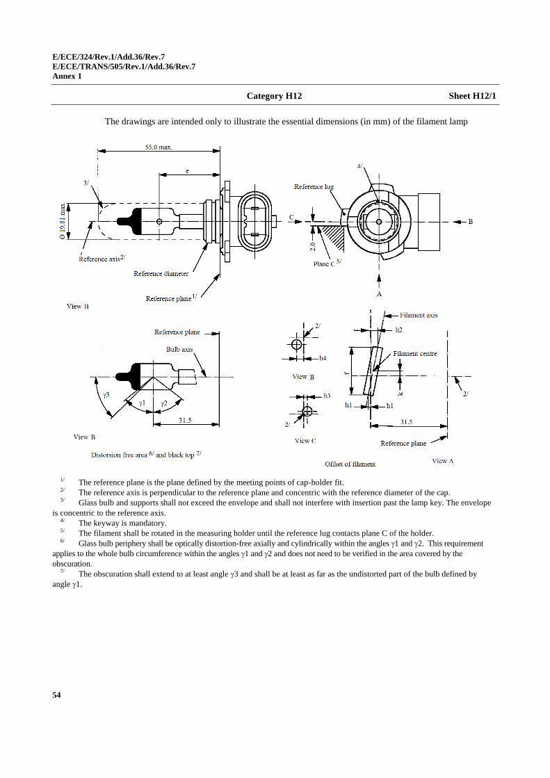
Category H12 Sheet H12/1
The drawings are intended only to illustrate the essential dimensions (in mm) of the filament lamp
1/ The reference plane is the plane defined by the meeting points of cap-holder fit. 2/ The reference axis is perpendicular to the reference plane and concentric with the reference diameter of the cap. 3/ Glass bulb and supports shall not exceed the envelope and shall not interfere with insertion past the lamp key. The envelope
is concentric to the reference axis. 4/ The keyway is mandatory. 5/ The filament shall be rotated in the measuring holder until the reference lug contacts plane C of the holder. 6/ Glass bulb periphery shall be optically distortion-free axially and cylindrically within the angles 1 and 2. This requirement
applies to the whole bulb circumference within the angles 1 and 2 and does not need to be verified in the area covered by the
obscuration. 7/ The obscuration shall extend to at least angle 3 and shall be at least as far as the undistorted part of the bulb defined by
angle 1.
E/ECE/324/Rev.1/Add.36/Rev.7
E/ECE/TRANS/505/Rev.1/Add.36/Rev.7
Annex 1
55
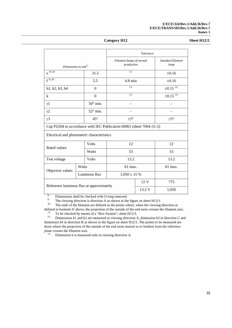
Category H12 Sheet H12/2
Dimensions in mm8/
Tolerance
Filament lamps of normal
production
Standard filament
lamp
e 9/,10/
31.5 11/
0.16
f 9/,10/
5.5 4.8 min 0.16
h1, h2, h3, h4 0 11/
0.15 12/
k 0 11/
0.15 13/
1 50° min. - -
2 52° min. - -
3 45° 5° 5°
Cap PZ20d in accordance with IEC Publication 60061 (sheet 7004-31-2)
Electrical and photometric characteristics
Rated values Volts 12 12
Watts 53 53
Test voltage Volts 13.2 13.2
Objective values Watts 61 max. 61 max.
Luminous flux 1,050 15 %
Reference luminous flux at approximately 12 V 775
13.2 V 1,050
8/ Dimensions shall be checked with O-ring removed. 9/ The viewing direction is direction A as shown in the figure on sheet H12/1. 10/ The ends of the filament are defined as the points where, when the viewing direction as
defined in footnote 9/ above, the projection of the outside of the end turns crosses the filament axis. 11/ To be checked by means of a "Box-System"; sheet H12/3. 12/ Dimensions h1 and h2 are measured in viewing direction A, dimension h3 in direction C and
dimension h4 in direction B as shown in the figure on sheet H12/1. The points to be measured are
those where the projection of the outside of the end turns nearest to or furthest from the reference
plane crosses the filament axis. 13/ Dimension k is measured only in viewing direction A.
E/ECE/324/Rev.1/Add.36/Rev.7
E/ECE/TRANS/505/Rev.1/Add.36/Rev.7
Annex 1
56
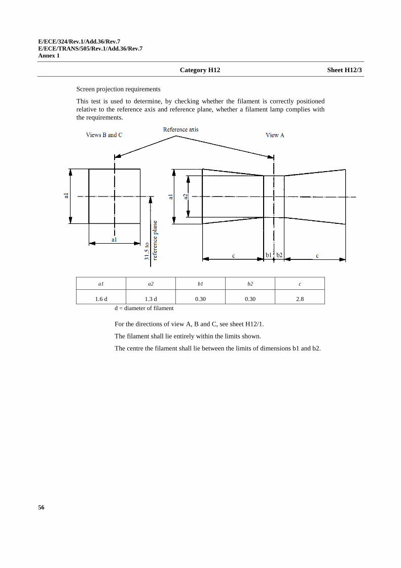
Category H12 Sheet H12/3
Screen projection requirements
This test is used to determine, by checking whether the filament is correctly positioned
relative to the reference axis and reference plane, whether a filament lamp complies with
the requirements.
a1 a2 b1 b2 c
1.6 d 1.3 d 0.30 0.30 2.8
d = diameter of filament
For the directions of view A, B and C, see sheet H12/1.
The filament shall lie entirely within the limits shown.
The centre the filament shall lie between the limits of dimensions b1 and b2.
E/ECE/324/Rev.1/Add.36/Rev.7
E/ECE/TRANS/505/Rev.1/Add.36/Rev.7
Annex 1
57
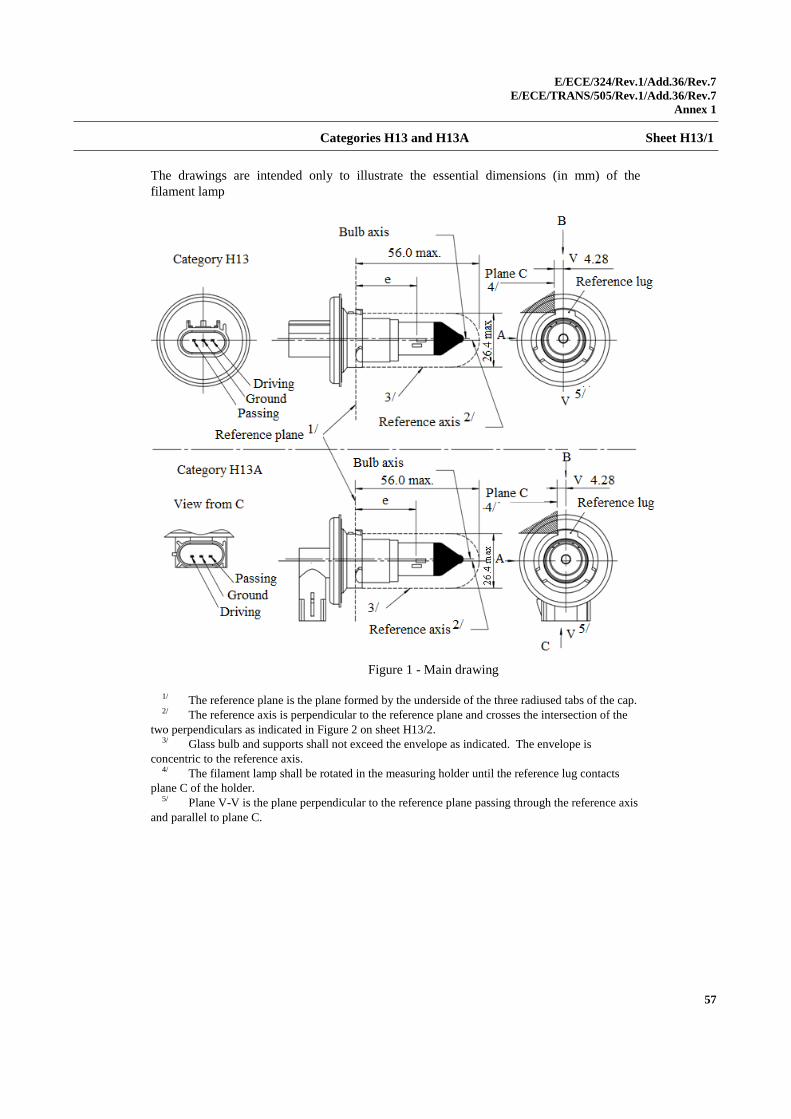
Categories H13 and H13A Sheet H13/1
The drawings are intended only to illustrate the essential dimensions (in mm) of the
filament lamp
Figure 1 - Main drawing
1/ The reference plane is the plane formed by the underside of the three radiused tabs of the cap. 2/ The reference axis is perpendicular to the reference plane and crosses the intersection of the
two perpendiculars as indicated in Figure 2 on sheet H13/2. 3/ Glass bulb and supports shall not exceed the envelope as indicated. The envelope is
concentric to the reference axis. 4/ The filament lamp shall be rotated in the measuring holder until the reference lug contacts
plane C of the holder. 5/ Plane V-V is the plane perpendicular to the reference plane passing through the reference axis
and parallel to plane C.
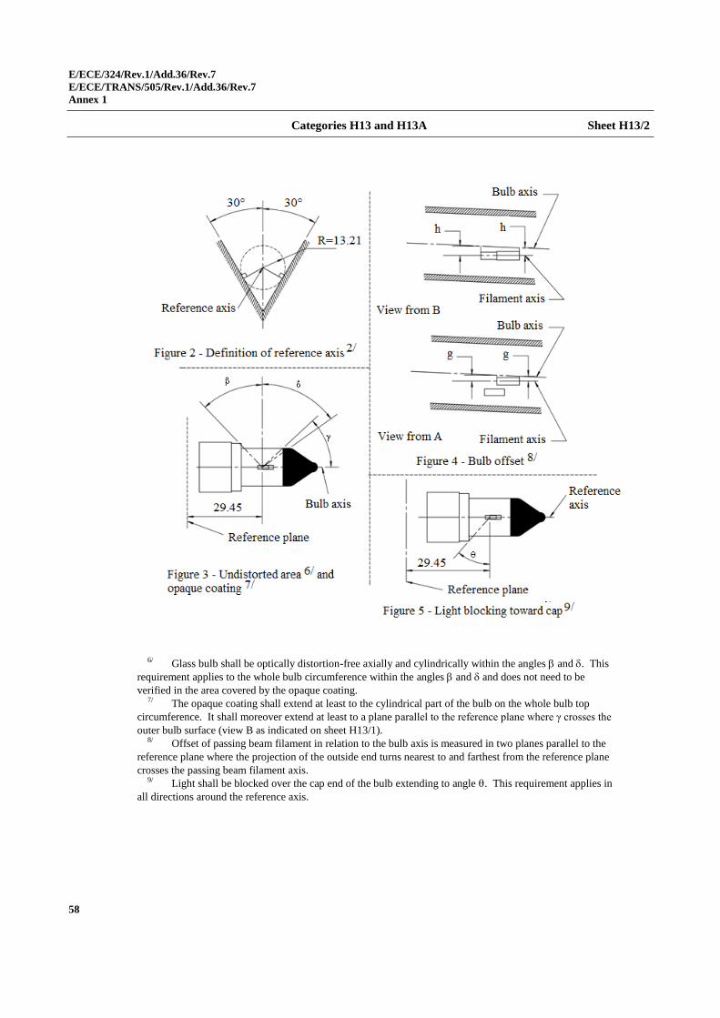
E/ECE/324/Rev.1/Add.36/Rev.7
E/ECE/TRANS/505/Rev.1/Add.36/Rev.7
Annex 1
58
Categories H13 and H13A Sheet H13/2
6/ Glass bulb shall be optically distortion-free axially and cylindrically within the angles and . This
requirement applies to the whole bulb circumference within the angles and and does not need to be
verified in the area covered by the opaque coating. 7/ The opaque coating shall extend at least to the cylindrical part of the bulb on the whole bulb top
circumference. It shall moreover extend at least to a plane parallel to the reference plane where γ crosses the
outer bulb surface (view B as indicated on sheet H13/1). 8/ Offset of passing beam filament in relation to the bulb axis is measured in two planes parallel to the
reference plane where the projection of the outside end turns nearest to and farthest from the reference plane
crosses the passing beam filament axis. 9/ Light shall be blocked over the cap end of the bulb extending to angle . This requirement applies in
all directions around the reference axis.
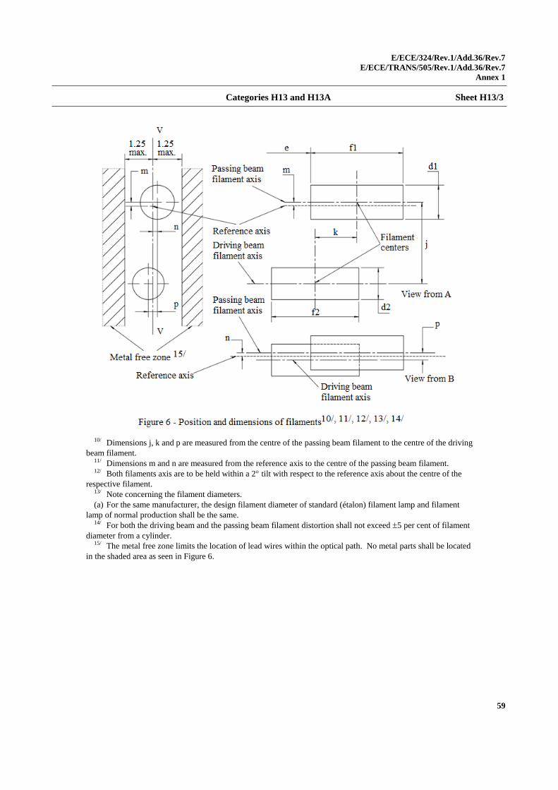
E/ECE/324/Rev.1/Add.36/Rev.7
E/ECE/TRANS/505/Rev.1/Add.36/Rev.7
Annex 1
59
Categories H13 and H13A Sheet H13/3
10/ Dimensions j, k and p are measured from the centre of the passing beam filament to the centre of the driving
beam filament. 11/ Dimensions m and n are measured from the reference axis to the centre of the passing beam filament. 12/ Both filaments axis are to be held within a 2 tilt with respect to the reference axis about the centre of the
respective filament. 13/ Note concerning the filament diameters.
(a) For the same manufacturer, the design filament diameter of standard (étalon) filament lamp and filament
lamp of normal production shall be the same. 14/ For both the driving beam and the passing beam filament distortion shall not exceed 5 per cent of filament
diameter from a cylinder. 15/ The metal free zone limits the location of lead wires within the optical path. No metal parts shall be located
in the shaded area as seen in Figure 6.
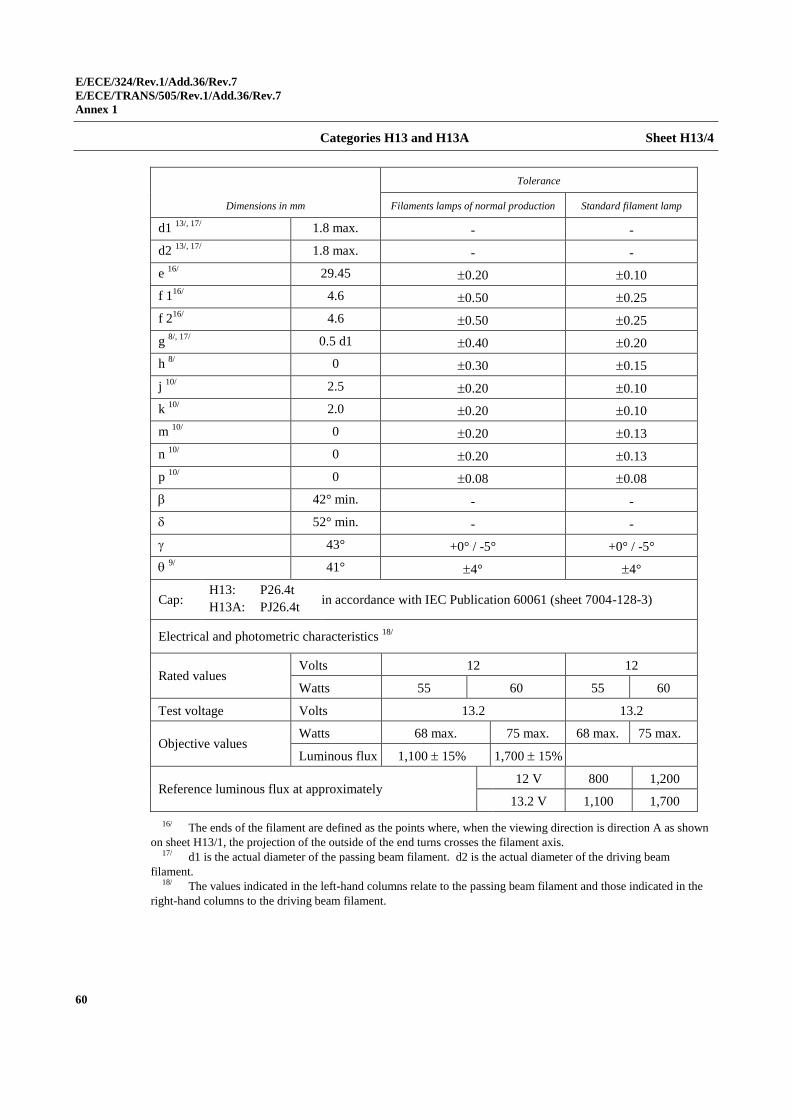
E/ECE/324/Rev.1/Add.36/Rev.7
E/ECE/TRANS/505/Rev.1/Add.36/Rev.7
Annex 1
60
Categories H13 and H13A Sheet H13/4
Dimensions in mm
Tolerance
Filaments lamps of normal production Standard filament lamp
d1 13/, 17/
1.8 max. - -
d2 13/, 17/
1.8 max. - -
e 16/
29.45 0.20 0.10
f 116/
4.6 0.50 0.25
f 216/
4.6 0.50 0.25
g 8/, 17/
0.5 d1 0.40 0.20
h 8/
0 0.30 0.15
j 10/
2.5 0.20 0.10
k 10/
2.0 0.20 0.10
m 10/
0 0.20 0.13
n 10/
0 0.20 0.13
p 10/
0 0.08 0.08
42° min. - -
52° min. - -
43° +0° / -5° +0° / -5°
9/
41° 4° 4°
Cap: H13: P26.4t
H13A: PJ26.4t in accordance with IEC Publication 60061 (sheet 7004-128-3)
Electrical and photometric characteristics 18/
Rated values Volts 12 12
Watts 55 60 55 60
Test voltage Volts 13.2 13.2
Objective values Watts 68 max. 75 max. 68 max. 75 max.
Luminous flux 1,100 15% 1,700 15%
Reference luminous flux at approximately 12 V 800 1,200
13.2 V 1,100 1,700
16/ The ends of the filament are defined as the points where, when the viewing direction is direction A as shown
on sheet H13/1, the projection of the outside of the end turns crosses the filament axis. 17/ d1 is the actual diameter of the passing beam filament. d2 is the actual diameter of the driving beam
filament. 18/ The values indicated in the left-hand columns relate to the passing beam filament and those indicated in the
right-hand columns to the driving beam filament.
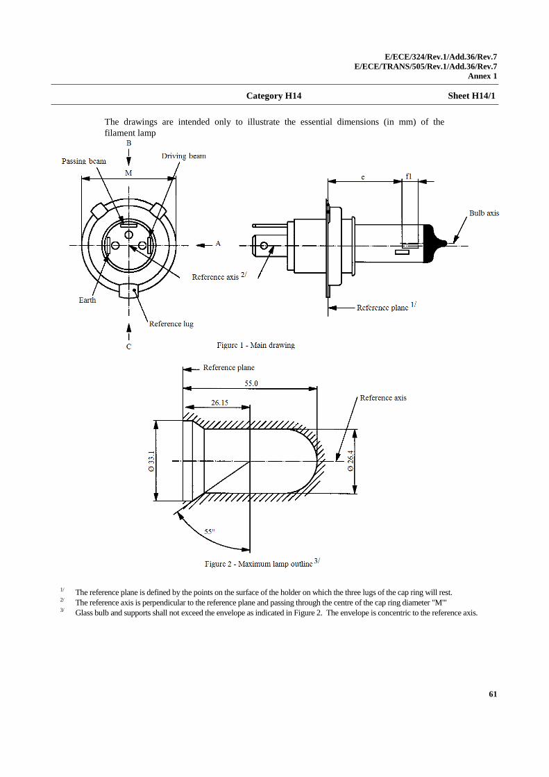
E/ECE/324/Rev.1/Add.36/Rev.7
E/ECE/TRANS/505/Rev.1/Add.36/Rev.7
Annex 1
61
Category H14 Sheet H14/1
The drawings are intended only to illustrate the essential dimensions (in mm) of the
filament lamp
1/ The reference plane is defined by the points on the surface of the holder on which the three lugs of the cap ring will rest. 2/ The reference axis is perpendicular to the reference plane and passing through the centre of the cap ring diameter "M'" 3/ Glass bulb and supports shall not exceed the envelope as indicated in Figure 2. The envelope is concentric to the reference axis.
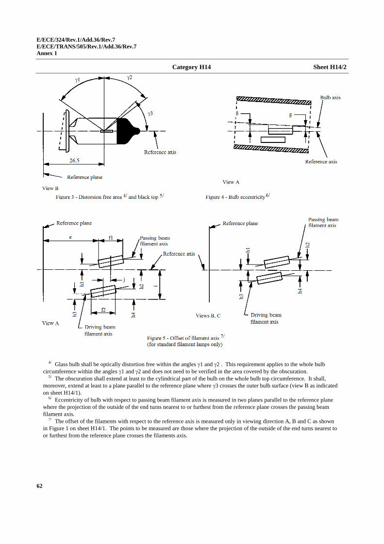
E/ECE/324/Rev.1/Add.36/Rev.7
E/ECE/TRANS/505/Rev.1/Add.36/Rev.7
Annex 1
62
Category H14 Sheet H14/2
4/ Glass bulb shall be optically distortion free within the angles 1 and 2 . This requirement applies to the whole bulb
circumference within the angles 1 and 2 and does not need to be verified in the area covered by the obscuration. 5/ The obscuration shall extend at least to the cylindrical part of the bulb on the whole bulb top circumference. It shall,
moreover, extend at least to a plane parallel to the reference plane where 3 crosses the outer bulb surface (view B as indicated
on sheet H14/1). 6/ Eccentricity of bulb with respect to passing beam filament axis is measured in two planes parallel to the reference plane
where the projection of the outside of the end turns nearest to or furthest from the reference plane crosses the passing beam
filament axis. 7/ The offset of the filaments with respect to the reference axis is measured only in viewing direction A, B and C as shown
in Figure 1 on sheet H14/1. The points to be measured are those where the projection of the outside of the end turns nearest to
or furthest from the reference plane crosses the filaments axis.
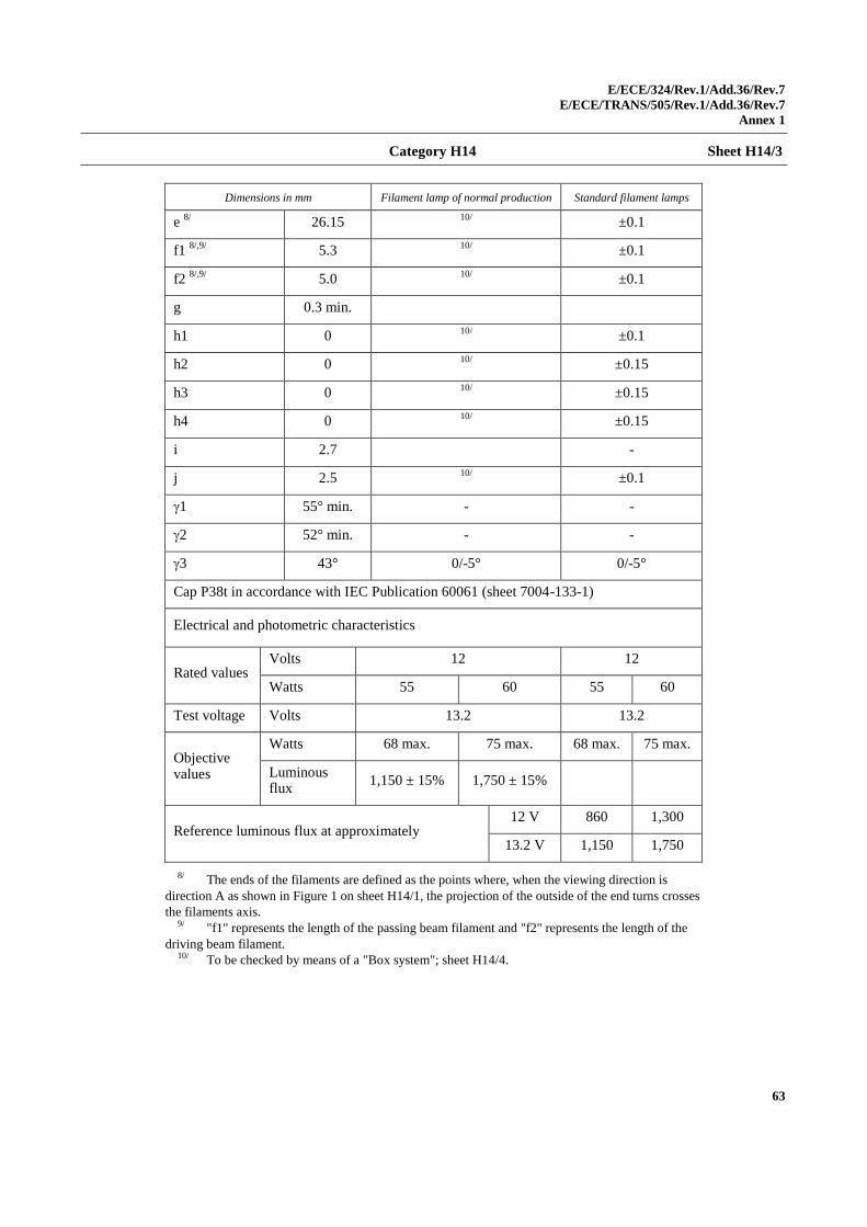
E/ECE/324/Rev.1/Add.36/Rev.7
E/ECE/TRANS/505/Rev.1/Add.36/Rev.7
Annex 1
63
Category H14 Sheet H14/3
Dimensions in mm Filament lamp of normal production Standard filament lamps
e 8/
26.15 10/
±0.1
f1 8/,9/
5.3 10/
±0.1
f2 8/,9/
5.0 10/
±0.1
g 0.3 min.
h1 0 10/
±0.1
h2 0 10/
±0.15
h3 0 10/
±0.15
h4 0 10/
±0.15
i 2.7 -
j 2.5 10/
±0.1
1 55° min. - -
2 52° min. - -
3 43° 0/-5° 0/-5°
Cap P38t in accordance with IEC Publication 60061 (sheet 7004-133-1)
Electrical and photometric characteristics
Rated values Volts 12 12
Watts 55 60 55 60
Test voltage Volts 13.2 13.2
Objective values
Watts 68 max. 75 max. 68 max. 75 max.
Luminous flux
1,150 ± 15% 1,750 ± 15%
Reference luminous flux at approximately 12 V 860 1,300
13.2 V 1,150 1,750
8/ The ends of the filaments are defined as the points where, when the viewing direction is
direction A as shown in Figure 1 on sheet H14/1, the projection of the outside of the end turns crosses
the filaments axis. 9/ "f1" represents the length of the passing beam filament and "f2" represents the length of the
driving beam filament. 10/ To be checked by means of a "Box system"; sheet H14/4.
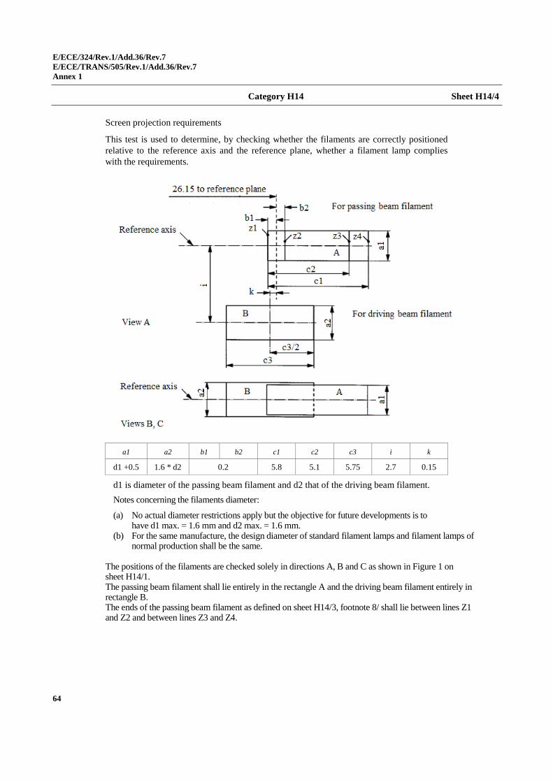
E/ECE/324/Rev.1/Add.36/Rev.7
E/ECE/TRANS/505/Rev.1/Add.36/Rev.7
Annex 1
64
Category H14 Sheet H14/4
Screen projection requirements
This test is used to determine, by checking whether the filaments are correctly positioned
relative to the reference axis and the reference plane, whether a filament lamp complies
with the requirements.
a1 a2 b1 b2 c1 c2 c3 i k
d1 +0.5 1.6 * d2 0.2 5.8 5.1 5.75 2.7 0.15
d1 is diameter of the passing beam filament and d2 that of the driving beam filament.
Notes concerning the filaments diameter:
(a) No actual diameter restrictions apply but the objective for future developments is to have d1 max. = 1.6 mm and d2 max. = 1.6 mm.
(b) For the same manufacture, the design diameter of standard filament lamps and filament lamps of normal production shall be the same.
The positions of the filaments are checked solely in directions A, B and C as shown in Figure 1 on sheet H14/1. The passing beam filament shall lie entirely in the rectangle A and the driving beam filament entirely in rectangle B. The ends of the passing beam filament as defined on sheet H14/3, footnote 8/ shall lie between lines Z1 and Z2 and between lines Z3 and Z4.
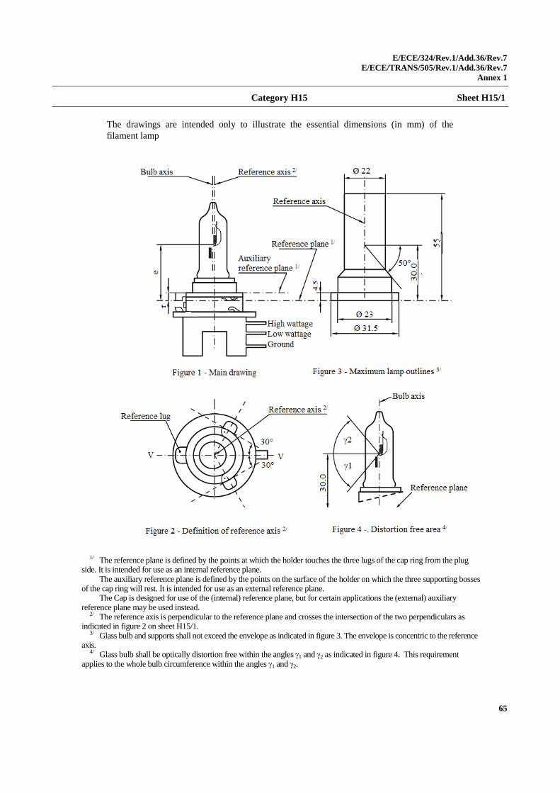
E/ECE/324/Rev.1/Add.36/Rev.7
E/ECE/TRANS/505/Rev.1/Add.36/Rev.7
Annex 1
65
Category H15 Sheet H15/1
The drawings are intended only to illustrate the essential dimensions (in mm) of the
filament lamp
1/ The reference plane is defined by the points at which the holder touches the three lugs of the cap ring from the plug side. It is intended for use as an internal reference plane.
The auxiliary reference plane is defined by the points on the surface of the holder on which the three supporting bosses of the cap ring will rest. It is intended for use as an external reference plane.
The Cap is designed for use of the (internal) reference plane, but for certain applications the (external) auxiliary reference plane may be used instead.
2/ The reference axis is perpendicular to the reference plane and crosses the intersection of the two perpendiculars as indicated in figure 2 on sheet H15/1.
3/ Glass bulb and supports shall not exceed the envelope as indicated in figure 3. The envelope is concentric to the reference axis.
4/ Glass bulb shall be optically distortion free within the angles 1 and 2 as indicated in figure 4. This requirement applies to the whole bulb circumference within the angles 1 and 2.
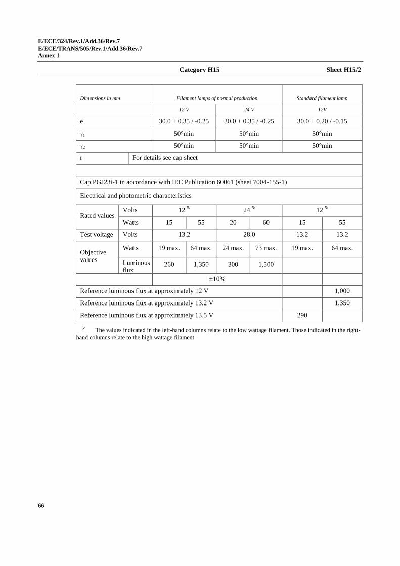
E/ECE/324/Rev.1/Add.36/Rev.7
E/ECE/TRANS/505/Rev.1/Add.36/Rev.7
Annex 1
66
Category H15 Sheet H15/2
Dimensions in mm Filament lamps of normal production Standard filament lamp
12 V 24 V 12V
e 30.0 + 0.35 / -0.25 30.0 + 0.35 / -0.25 30.0 + 0.20 / -0.15
1 50°min 50°min 50°min
2 50°min 50°min 50°min
r For details see cap sheet
Cap PGJ23t-1 in accordance with IEC Publication 60061 (sheet 7004-155-1)
Electrical and photometric characteristics
Rated values Volts 12
5/ 24
5/ 12
5/
Watts 15 55 20 60 15 55
Test voltage Volts 13.2 28.0 13.2 13.2
Objective values
Watts 19 max. 64 max. 24 max. 73 max. 19 max. 64 max.
Luminous flux
260 1,350 300 1,500
10%
Reference luminous flux at approximately 12 V 1,000
Reference luminous flux at approximately 13.2 V 1,350
Reference luminous flux at approximately 13.5 V 290
5/ The values indicated in the left-hand columns relate to the low wattage filament. Those indicated in the right-
hand columns relate to the high wattage filament.
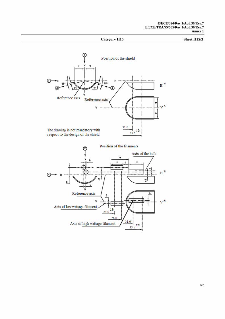
E/ECE/324/Rev.1/Add.36/Rev.7
E/ECE/TRANS/505/Rev.1/Add.36/Rev.7
Annex 1
67
Category H15 Sheet H15/3
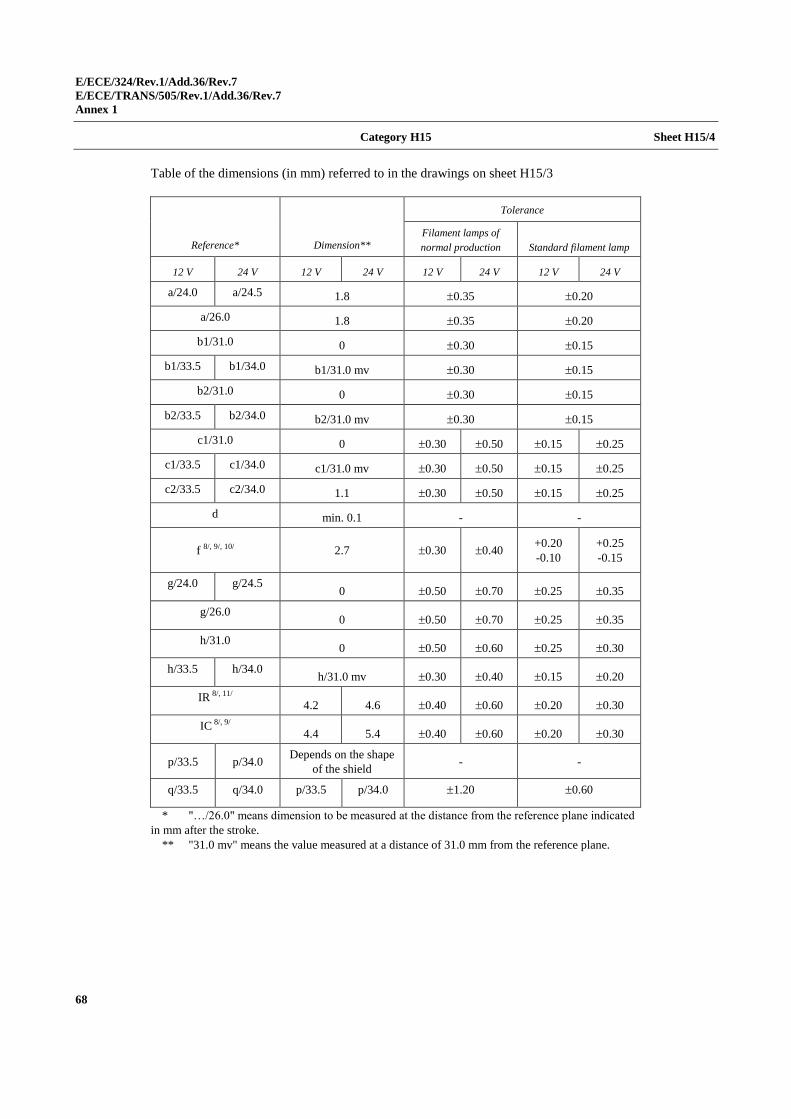
E/ECE/324/Rev.1/Add.36/Rev.7
E/ECE/TRANS/505/Rev.1/Add.36/Rev.7
Annex 1
68
Category H15 Sheet H15/4
Table of the dimensions (in mm) referred to in the drawings on sheet H15/3
Reference* Dimension**
Tolerance
Filament lamps of
normal production Standard filament lamp
12 V 24 V 12 V 24 V 12 V 24 V 12 V 24 V
a/24.0 a/24.5 1.8 0.35 0.20
a/26.0 1.8 0.35 0.20
b1/31.0 0 0.30 0.15
b1/33.5 b1/34.0 b1/31.0 mv 0.30 0.15
b2/31.0 0 0.30 0.15
b2/33.5 b2/34.0 b2/31.0 mv 0.30 0.15
c1/31.0 0 0.30 0.50 0.15 0.25
c1/33.5 c1/34.0 c1/31.0 mv 0.30 0.50 0.15 0.25
c2/33.5 c2/34.0 1.1 0.30 0.50 0.15 0.25
d min. 0.1 - -
f 8/, 9/, 10/ 2.7 0.30 0.40 +0.20
-0.10
+0.25
-0.15
g/24.0 g/24.5 0 0.50 0.70 0.25 0.35
g/26.0 0 0.50 0.70 0.25 0.35
h/31.0 0 0.50 0.60 0.25 0.30
h/33.5 h/34.0 h/31.0 mv 0.30 0.40 0.15 0.20
IR 8/, 11/
4.2 4.6 0.40 0.60 0.20 0.30
IC 8/, 9/
4.4 5.4 0.40 0.60 0.20 0.30
p/33.5 p/34.0 Depends on the shape
of the shield - -
q/33.5 q/34.0 p/33.5 p/34.0 1.20 0.60
* "…/26.0" means dimension to be measured at the distance from the reference plane indicated
in mm after the stroke.
** "31.0 mv" means the value measured at a distance of 31.0 mm from the reference plane.
E/ECE/324/Rev.1/Add.36/Rev.7
E/ECE/TRANS/505/Rev.1/Add.36/Rev.7
Annex 1
69
Category H15 Sheet H15/5
6/ Plane V-V is the plane perpendicular to the reference plane and passing through the reference
axis and through the axis of the reference lug. 7/ Plane H-H is the plane perpendicular to both the reference plane and plane V-V and passing
through the reference axis. 8/ The end turns of the filament are defined as being the first luminous turn and the last
luminous turn that are at substantially the correct helix angle. 9/ For the high wattage filament, the points to be measured are the intersections, seen in
direction 1, of the lateral edge of the shield with the outside of the end turns defined under
footnote 8/. 10/ "e" denotes the distance from the reference plane to the beginning of the driving beam
filament as defined above. 11/ For the low wattage filament the points to be measured are the intersections, seen in
direction 1, of a plane, parallel to plane H-H and situated at a distance of 1.8 mm above it, with the
end turns defined under footnote 8/. 12/ 34.0 for the 24 V type. 13/ 24.5 for the 24 V type.
Additional explanations to sheet H15/3
The dimensions below are measured in four directions:
1) For dimensions a, c1, c2, d, e, f, lR and lC;
2) For dimensions g, h, p and q;
3) For dimension b1;
4) For dimension b2.
Dimensions b1, b2, c1 and h are measured in planes parallel to the reference
plane at distances of 31.0 mm and 33.5 mm (34.0 mm for 24 V types).
Dimensions c2, p and q are measured in a plane parallel to the reference
plane at a distance of 33.5 mm (34.0 mm for 24 V types).
Dimensions a and g are measured in planes parallel to the reference plane at
distances of 24.0 mm (24.5 mm for 24 V types) and 26.0 mm.
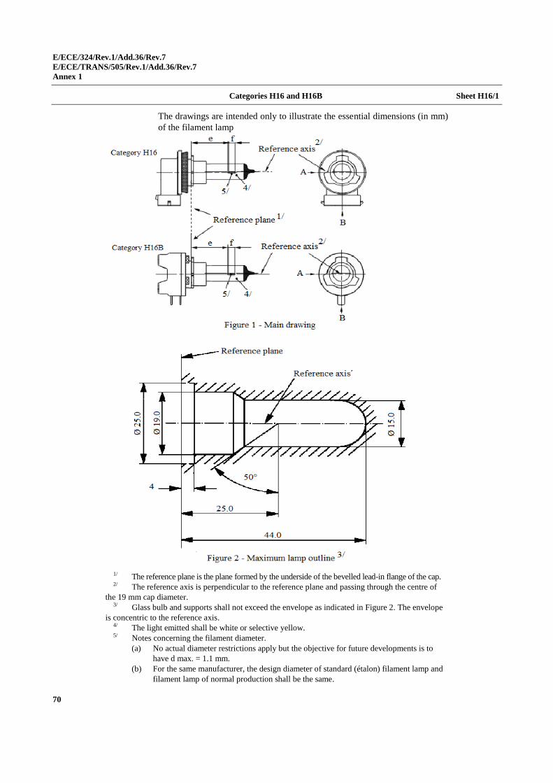
E/ECE/324/Rev.1/Add.36/Rev.7
E/ECE/TRANS/505/Rev.1/Add.36/Rev.7
Annex 1
70
Categories H16 and H16B Sheet H16/1
The drawings are intended only to illustrate the essential dimensions (in mm)
of the filament lamp
1/ The reference plane is the plane formed by the underside of the bevelled lead-in flange of the cap. 2/ The reference axis is perpendicular to the reference plane and passing through the centre of
the 19 mm cap diameter. 3/ Glass bulb and supports shall not exceed the envelope as indicated in Figure 2. The envelope
is concentric to the reference axis. 4/ The light emitted shall be white or selective yellow. 5/ Notes concerning the filament diameter.
(a) No actual diameter restrictions apply but the objective for future developments is to
have d max. = 1.1 mm.
(b) For the same manufacturer, the design diameter of standard (étalon) filament lamp and
filament lamp of normal production shall be the same.
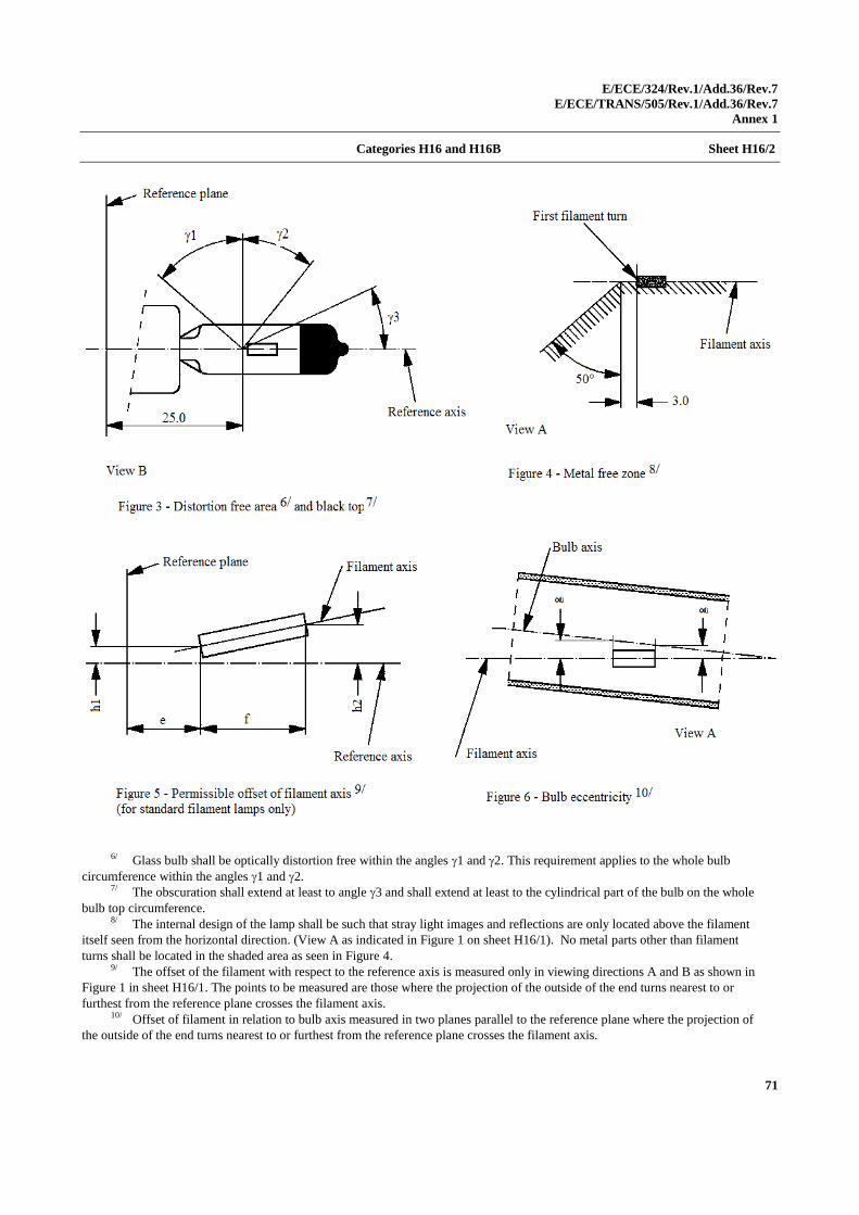
E/ECE/324/Rev.1/Add.36/Rev.7
E/ECE/TRANS/505/Rev.1/Add.36/Rev.7
Annex 1
71
Categories H16 and H16B Sheet H16/2
6/ Glass bulb shall be optically distortion free within the angles 1 and 2. This requirement applies to the whole bulb
circumference within the angles 1 and 2. 7/ The obscuration shall extend at least to angle 3 and shall extend at least to the cylindrical part of the bulb on the whole
bulb top circumference. 8/ The internal design of the lamp shall be such that stray light images and reflections are only located above the filament
itself seen from the horizontal direction. (View A as indicated in Figure 1 on sheet H16/1). No metal parts other than filament
turns shall be located in the shaded area as seen in Figure 4. 9/ The offset of the filament with respect to the reference axis is measured only in viewing directions A and B as shown in
Figure 1 in sheet H16/1. The points to be measured are those where the projection of the outside of the end turns nearest to or
furthest from the reference plane crosses the filament axis. 10/ Offset of filament in relation to bulb axis measured in two planes parallel to the reference plane where the projection of
the outside of the end turns nearest to or furthest from the reference plane crosses the filament axis.
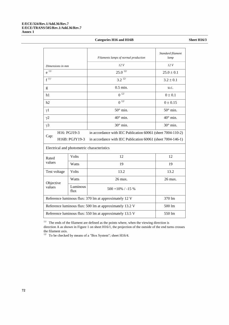
E/ECE/324/Rev.1/Add.36/Rev.7
E/ECE/TRANS/505/Rev.1/Add.36/Rev.7
Annex 1
72
Categories H16 and H16B Sheet H16/3
Dimensions in mm
Filaments lamps of normal production
Standard filament
lamp
12 V 12 V
e 11/
25.0 12/
25.0 0.1
f 11/
3.2 12/
3.2 0.1
g 0.5 min. u.c.
h1 0 12/
0 0.1
h2 0 12/
0 0.15
1 50° min. 50° min.
2 40° min. 40° min.
3 30° min. 30° min.
Cap: H16: PGJ19-3
H16B: PGJY19-3
in accordance with IEC Publication 60061 (sheet 7004-110-2)
in accordance with IEC Publication 60061 (sheet 7004-146-1)
Electrical and photometric characteristics
Rated values
Volts 12 12
Watts 19 19
Test voltage Volts 13.2 13.2
Objective values
Watts 26 max. 26 max.
Luminous flux
500 +10% / -15 %
Reference luminous flux: 370 lm at approximately 12 V 370 lm
Reference luminous flux: 500 lm at approximately 13.2 V 500 lm
Reference luminous flux: 550 lm at approximately 13.5 V 550 lm
11/ The ends of the filament are defined as the points where, when the viewing direction is
direction A as shown in Figure 1 on sheet H16/1, the projection of the outside of the end turns crosses
the filament axis.
12/ To be checked by means of a "Box System"; sheet H16/4.
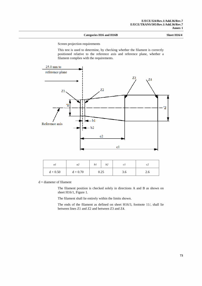
E/ECE/324/Rev.1/Add.36/Rev.7
E/ECE/TRANS/505/Rev.1/Add.36/Rev.7
Annex 1
73
Categories H16 and H16B Sheet H16/4
Screen projection requirements
This test is used to determine, by checking whether the filament is correctly
positioned relative to the reference axis and reference plane, whether a
filament complies with the requirements.
a1 a2 b1 b2 c1 c2
d + 0.50 d + 0.70 0.25 3.6 2.6
d = diameter of filament
The filament position is checked solely in directions A and B as shown on
sheet H16/1, Figure 1.
The filament shall lie entirely within the limits shown.
The ends of the filament as defined on sheet H16/3, footnote 11/, shall lie
between lines Z1 and Z2 and between Z3 and Z4.
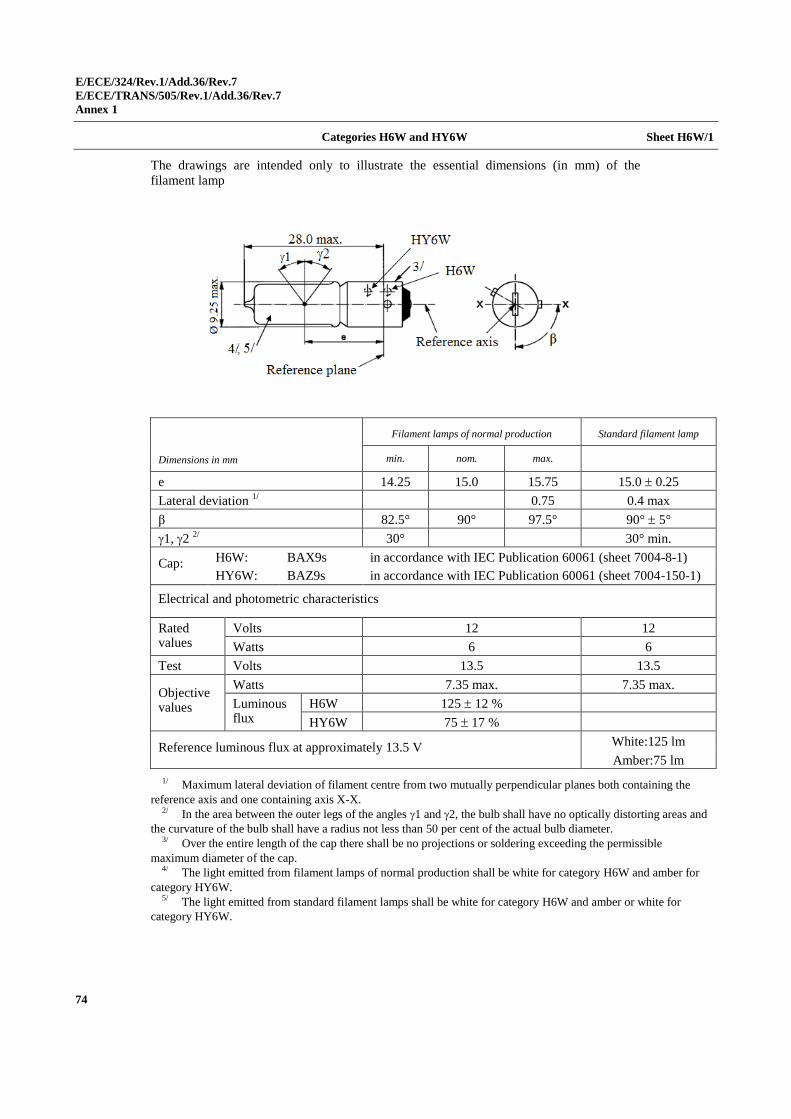
E/ECE/324/Rev.1/Add.36/Rev.7
E/ECE/TRANS/505/Rev.1/Add.36/Rev.7
Annex 1
74
Categories H6W and HY6W Sheet H6W/1
The drawings are intended only to illustrate the essential dimensions (in mm) of the
filament lamp
Dimensions in mm
Filament lamps of normal production Standard filament lamp
min. nom. max.
e 14.25 15.0 15.75 15.0 0.25
Lateral deviation 1/
0.75 0.4 max
β 82.5° 90° 97.5° 90° 5°
1, 2 2/
30° 30° min.
Cap: H6W: BAX9s in accordance with IEC Publication 60061 (sheet 7004-8-1)
HY6W: BAZ9s in accordance with IEC Publication 60061 (sheet 7004-150-1)
Electrical and photometric characteristics
Rated values
Volts 12 12
Watts 6 6
Test voltage
Volts 13.5 13.5
Objective values
Watts 7.35 max. 7.35 max.
Luminous flux
H6W 125 12 %
HY6W 75 17 %
Reference luminous flux at approximately 13.5 V White:125 lm
Amber:75 lm
1/ Maximum lateral deviation of filament centre from two mutually perpendicular planes both containing the
reference axis and one containing axis X-X. 2/ In the area between the outer legs of the angles 1 and 2, the bulb shall have no optically distorting areas and
the curvature of the bulb shall have a radius not less than 50 per cent of the actual bulb diameter. 3/ Over the entire length of the cap there shall be no projections or soldering exceeding the permissible
maximum diameter of the cap. 4/ The light emitted from filament lamps of normal production shall be white for category H6W and amber for
category HY6W. 5/ The light emitted from standard filament lamps shall be white for category H6W and amber or white for
category HY6W.
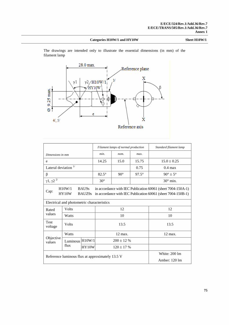
E/ECE/324/Rev.1/Add.36/Rev.7
E/ECE/TRANS/505/Rev.1/Add.36/Rev.7
Annex 1
75
Categories H10W/1 and HY10W Sheet H10W/1
The drawings are intended only to illustrate the essential dimensions (in mm) of the
filament lamp
Dimensions in mm
Filament lamps of normal production Standard filament lamp
min. nom. max.
e 14.25 15.0 15.75 15.0 0.25
Lateral deviation 1/
0.75 0.4 max
β 82.5° 90° 97.5° 90° 5°
1, 2 2/
30° 30° min.
Cap: H10W/1
HY10W
BAU9s
BAUZ9s
in accordance with IEC Publication 60061 (sheet 7004-150A-1)
in accordance with IEC Publication 60061 (sheet 7004-150B-1)
Electrical and photometric characteristics
Rated values
Volts 12 12
Watts 10 10
Test voltage
Volts 13.5 13.5
Objective values
Watts 12 max. 12 max.
Luminous flux
H10W/1 200 12 %
HY10W 120 17 %
Reference luminous flux at approximately 13.5 V White: 200 lm
Amber: 120 lm

E/ECE/324/Rev.1/Add.36/Rev.7
E/ECE/TRANS/505/Rev.1/Add.36/Rev.7
Annex 1
76
Categories H10W and HY10W Sheet H10W/2
1/ Maximum lateral deviation of filament centre from two mutually perpendicular planes both
containing the reference axis and one containing axis X-X. 2/ In the area between the outer legs of the angles 1 and 2, the bulb shall have no optically
distorting areas and the curvature of the bulb shall have a radius not less than 50 per cent of the actual
bulb diameter. 3/ Over the entire length of the cap there shall be no projections or soldering exceeding the
permissible maximum diameter of the cap. 4/ The light emitted from filament lamps of normal production shall be white for
category H10W/1 and amber for category HY10W. 5/ The light emitted from standard filament lamps shall be white for category H10W/1 and
amber or white for category HY10W.
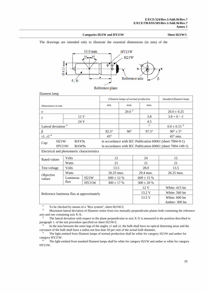
E/ECE/324/Rev.1/Add.36/Rev.7
E/ECE/TRANS/505/Rev.1/Add.36/Rev.7
Annex 1
77
Categories H21W and HY21W Sheet H21W/1
The drawings are intended only to illustrate the essential dimensions (in mm) of the
filament lamp
Dimensions in mm
Filament lamps of normal production Standard filament lamp
min. nom. max.
e 20.0 1/ 20.0 0.25
f 12 V 3.8 3.8 + 0 / -1
24 V 4.5
Lateral deviation 2/
1/
0.0 0.15 3/
82.5° 90° 97.5° 90° 5°
1, 2 4/
45° 45° min.
Cap: H21W: BAY9s in accordance with IEC Publication 60061 (sheet 7004-9-1)
HY21W: BAW9s in accordance with IEC Publication 60061 (sheet 7004-149-1)
Electrical and photometric characteristics
Rated values Volts 12 24 12
Watts 21 21 21
Test voltage Volts 13.5 28.0 13.5
Objective values
Watts 26.25 max. 29.4 max. 26.25 max.
Luminous flux
H21W 600 12 % 600 15 %
HY21W 300 17 % 300 20 %
Reference luminous flux at approximately
12 V White: 415 lm
13.2 V White: 560 lm
13.5 V White: 600 lm
Amber: 300 lm 1/ To be checked by means of a "Box system", sheet H21W/2. 2/ Maximum lateral deviation of filament centre from two mutually perpendicular planes both containing the reference
axis and one containing axis X-X. 3/ The lateral deviation with respect to the plane perpendicular to axis X-X is measured in the position described in
paragraph 1. of the test procedure specified on sheet H21W/2. 4/ In the area between the outer legs of the angles 1 and 2, the bulb shall have no optical distorting areas and the
curvature of the bulb shall have a radius not less than 50 per cent of the actual bulb diameter. 5/ The light emitted from filament lamps of normal production shall be white for category H21W and amber for
category HY21W. 6/ The light emitted from standard filament lamps shall be white for category H21W and amber or white for category
HY21W.
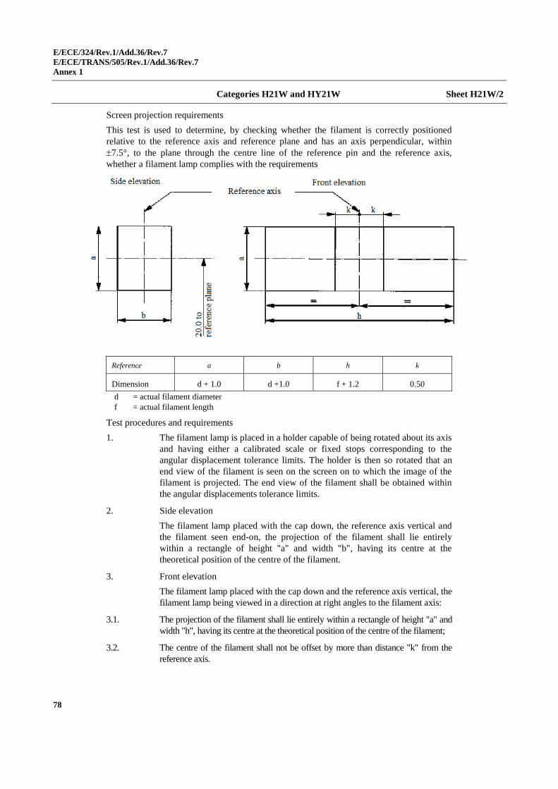
E/ECE/324/Rev.1/Add.36/Rev.7
E/ECE/TRANS/505/Rev.1/Add.36/Rev.7
Annex 1
78
Categories H21W and HY21W Sheet H21W/2
Screen projection requirements
This test is used to determine, by checking whether the filament is correctly positioned
relative to the reference axis and reference plane and has an axis perpendicular, within
7.5°, to the plane through the centre line of the reference pin and the reference axis,
whether a filament lamp complies with the requirements
Reference a b h k
Dimension d + 1.0 d +1.0 f + 1.2 0.50
d = actual filament diameter
f = actual filament length
Test procedures and requirements
1. The filament lamp is placed in a holder capable of being rotated about its axis
and having either a calibrated scale or fixed stops corresponding to the
angular displacement tolerance limits. The holder is then so rotated that an
end view of the filament is seen on the screen on to which the image of the
filament is projected. The end view of the filament shall be obtained within
the angular displacements tolerance limits.
2. Side elevation
The filament lamp placed with the cap down, the reference axis vertical and
the filament seen end-on, the projection of the filament shall lie entirely
within a rectangle of height "a" and width "b", having its centre at the
theoretical position of the centre of the filament.
3. Front elevation
The filament lamp placed with the cap down and the reference axis vertical, the
filament lamp being viewed in a direction at right angles to the filament axis:
3.1. The projection of the filament shall lie entirely within a rectangle of height "a" and
width "h", having its centre at the theoretical position of the centre of the filament;
3.2. The centre of the filament shall not be offset by more than distance "k" from the
reference axis.
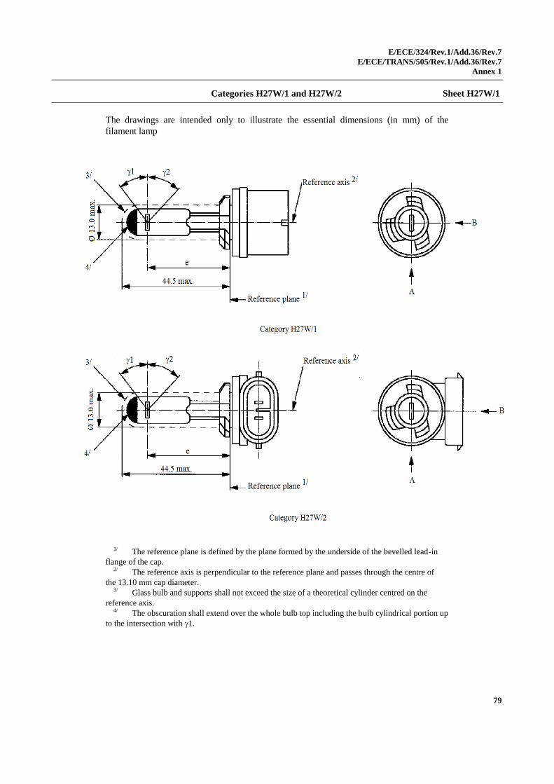
E/ECE/324/Rev.1/Add.36/Rev.7
E/ECE/TRANS/505/Rev.1/Add.36/Rev.7
Annex 1
79
Categories H27W/1 and H27W/2 Sheet H27W/1
The drawings are intended only to illustrate the essential dimensions (in mm) of the
filament lamp
1/ The reference plane is defined by the plane formed by the underside of the bevelled lead-in
flange of the cap. 2/ The reference axis is perpendicular to the reference plane and passes through the centre of
the 13.10 mm cap diameter. 3/ Glass bulb and supports shall not exceed the size of a theoretical cylinder centred on the
reference axis. 4/ The obscuration shall extend over the whole bulb top including the bulb cylindrical portion up
to the intersection with 1.
1
3.0
max
.
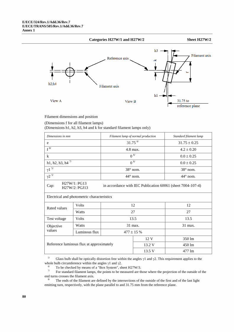
E/ECE/324/Rev.1/Add.36/Rev.7
E/ECE/TRANS/505/Rev.1/Add.36/Rev.7
Annex 1
80
Categories H27W/1 and H27W/2 Sheet H27W/2
Filament dimensions and position
(Dimensions f for all filament lamps)
(Dimensions h1, h2, h3, h4 and k for standard filament lamps only)
Dimensions in mm Filament lamp of normal production Standard filament lamp
e 31.75 6/ 31.75 0.25
f 8/
4.8 max. 4.2 0.20
k 0 6/
0.0 0.25
h1, h2, h3, h4 7/
0 6/
0.0 0.25
1 5/
38° nom. 38° nom.
2 5/
44° nom. 44° nom.
Cap: H27W/1: PG13 H27W/2: PGJ13
in accordance with IEC Publication 60061 (sheet 7004-107-4)
Electrical and photometric characteristics
Rated values Volts 12 12
Watts 27 27
Test voltage Volts 13.5 13.5
Objective values
Watts 31 max. 31 max.
Luminous flux 477 15 %
Reference luminous flux at approximately
12 V 350 lm
13.2 V 450 lm
13.5 V 477 lm
5/ Glass bulb shall be optically distortion free within the angles 1 and 2. This requirement applies to the
whole bulb circumference within the angles 1 and 2. 6/ To be checked by means of a "Box System", sheet H27W/3. 7/ For standard filament lamps, the points to be measured are those where the projection of the outside of the
end turns crosses the filament axis. 8/ The ends of the filament are defined by the intersections of the outside of the first and of the last light
emitting turn, respectively, with the plane parallel to and 31.75 mm from the reference plane.
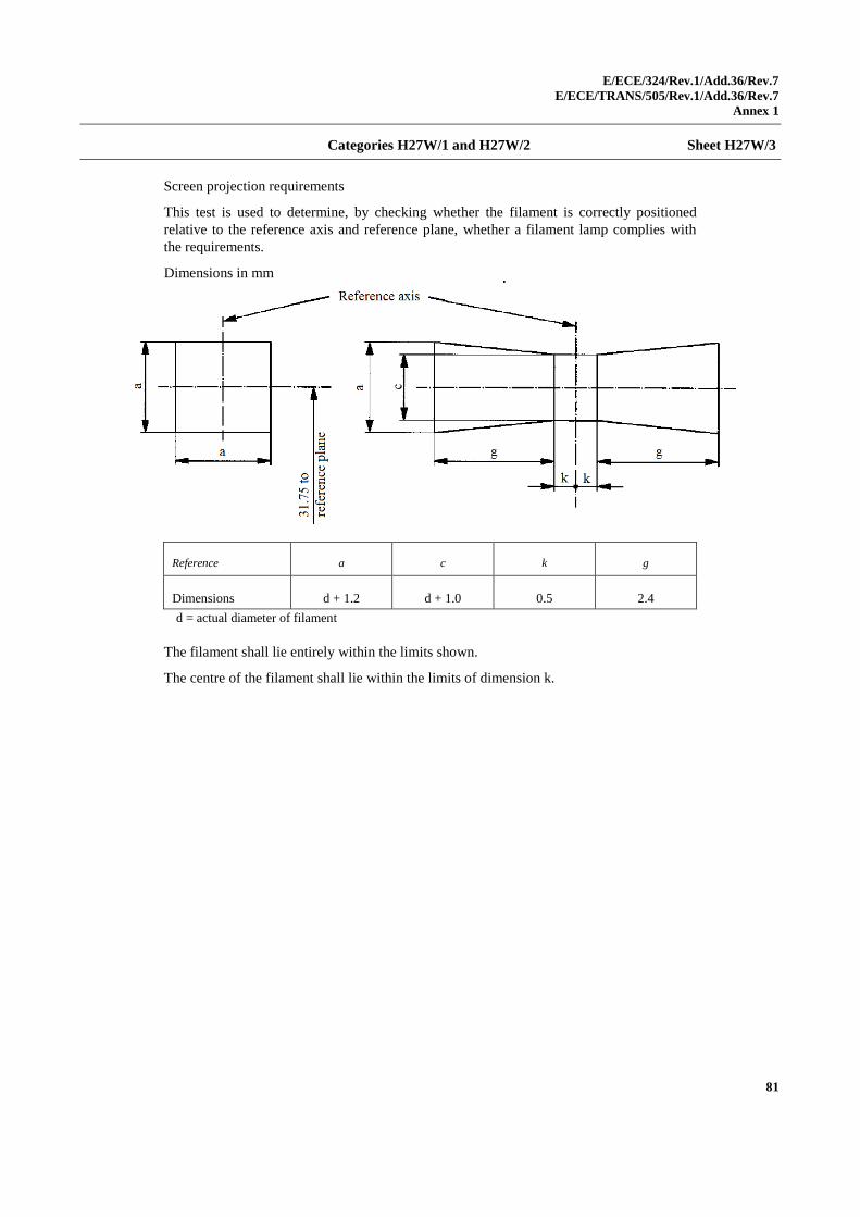
E/ECE/324/Rev.1/Add.36/Rev.7
E/ECE/TRANS/505/Rev.1/Add.36/Rev.7
Annex 1
81
Categories H27W/1 and H27W/2 Sheet H27W/3
Screen projection requirements
This test is used to determine, by checking whether the filament is correctly positioned
relative to the reference axis and reference plane, whether a filament lamp complies with
the requirements.
Dimensions in mm
Reference a c k g
Dimensions d + 1.2 d + 1.0 0.5 2.4
d = actual diameter of filament
The filament shall lie entirely within the limits shown.
The centre of the filament shall lie within the limits of dimension k.
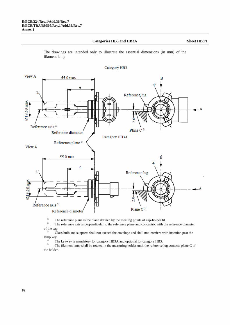
E/ECE/324/Rev.1/Add.36/Rev.7
E/ECE/TRANS/505/Rev.1/Add.36/Rev.7
Annex 1
82
Categories HB3 and HB3A Sheet HB3/1
The drawings are intended only to illustrate the essential dimensions (in mm) of the
filament lamp
1/ The reference plane is the plane defined by the meeting points of cap-holder fit. 2/ The reference axis is perpendicular to the reference plane and concentric with the reference diameter
of the cap. 3/ Glass bulb and supports shall not exceed the envelope and shall not interfere with insertion past the
lamp key. 4/ The keyway is mandatory for category HB3A and optional for category HB3. 5/ The filament lamp shall be rotated in the measuring holder until the reference lug contacts plane C of
the holder.
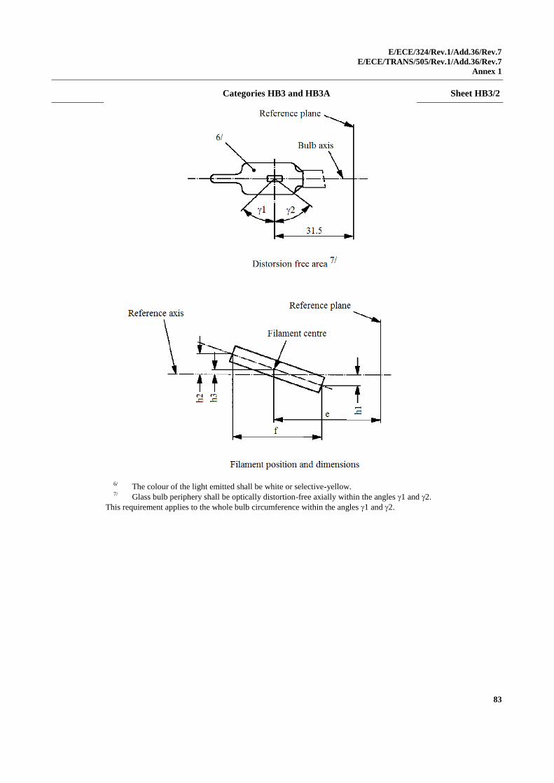
E/ECE/324/Rev.1/Add.36/Rev.7
E/ECE/TRANS/505/Rev.1/Add.36/Rev.7
Annex 1
83
Categories HB3 and HB3A Sheet HB3/2
6/ The colour of the light emitted shall be white or selective-yellow. 7/ Glass bulb periphery shall be optically distortion-free axially within the angles 1 and 2.
This requirement applies to the whole bulb circumference within the angles 1 and 2.
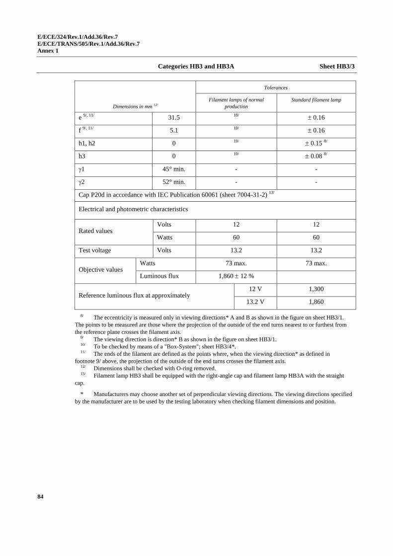
E/ECE/324/Rev.1/Add.36/Rev.7
E/ECE/TRANS/505/Rev.1/Add.36/Rev.7
Annex 1
84
Categories HB3 and HB3A Sheet HB3/3
Dimensions in mm 12/
Tolerances
Filament lamps of normal
production
Standard filament lamp
e 9/, 11/
31.5 10/
0.16
f 9/, 11/
5.1 10/
0.16
h1, h2 0 10/
0.15 8/
h3 0 10/
0.08 8/
1 45° min. - -
2 52° min. - -
Cap P20d in accordance with IEC Publication 60061 (sheet 7004-31-2) 13/
Electrical and photometric characteristics
Rated values Volts 12 12
Watts 60 60
Test voltage Volts 13.2 13.2
Objective values Watts 73 max. 73 max.
Luminous flux 1,860 12 %
Reference luminous flux at approximately 12 V 1,300
13.2 V 1,860
8/ The eccentricity is measured only in viewing directions* A and B as shown in the figure on sheet HB3/1.
The points to be measured are those where the projection of the outside of the end turns nearest to or furthest from
the reference plane crosses the filament axis. 9/ The viewing direction is direction* B as shown in the figure on sheet HB3/1. 10/ To be checked by means of a "Box-System"; sheet HB3/4*. 11/ The ends of the filament are defined as the points where, when the viewing direction* as defined in
footnote 9/ above, the projection of the outside of the end turns crosses the filament axis. 12/ Dimensions shall be checked with O-ring removed. 13/ Filament lamp HB3 shall be equipped with the right-angle cap and filament lamp HB3A with the straight
cap.
* Manufacturers may choose another set of perpendicular viewing directions. The viewing directions specified
by the manufacturer are to be used by the testing laboratory when checking filament dimensions and position.
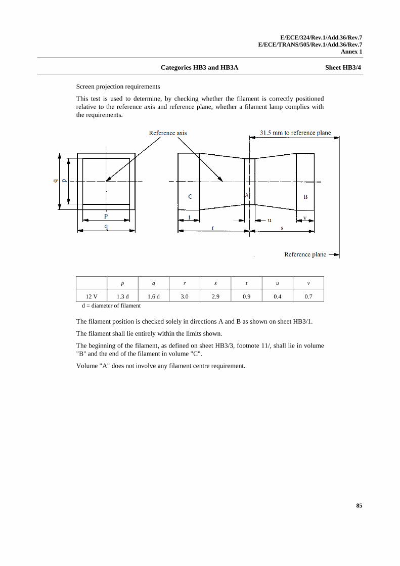
E/ECE/324/Rev.1/Add.36/Rev.7
E/ECE/TRANS/505/Rev.1/Add.36/Rev.7
Annex 1
85
Categories HB3 and HB3A Sheet HB3/4
Screen projection requirements
This test is used to determine, by checking whether the filament is correctly positioned
relative to the reference axis and reference plane, whether a filament lamp complies with
the requirements.
p q r s t u v
12 V 1.3 d 1.6 d 3.0 2.9 0.9 0.4 0.7
d = diameter of filament
The filament position is checked solely in directions A and B as shown on sheet HB3/1.
The filament shall lie entirely within the limits shown.
The beginning of the filament, as defined on sheet HB3/3, footnote 11/, shall lie in volume
"B" and the end of the filament in volume "C".
Volume "A" does not involve any filament centre requirement.
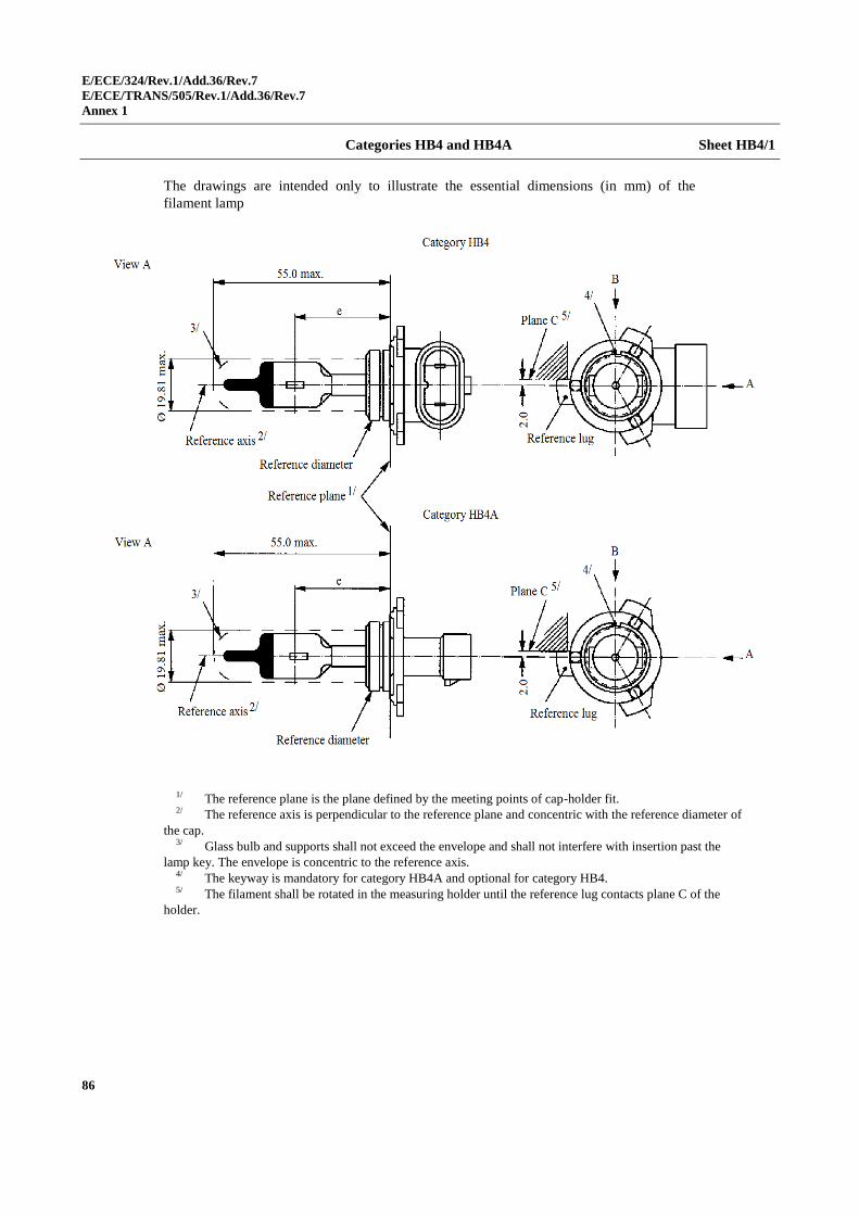
E/ECE/324/Rev.1/Add.36/Rev.7
E/ECE/TRANS/505/Rev.1/Add.36/Rev.7
Annex 1
86
Categories HB4 and HB4A Sheet HB4/1
The drawings are intended only to illustrate the essential dimensions (in mm) of the
filament lamp
1/ The reference plane is the plane defined by the meeting points of cap-holder fit. 2/ The reference axis is perpendicular to the reference plane and concentric with the reference diameter of
the cap. 3/ Glass bulb and supports shall not exceed the envelope and shall not interfere with insertion past the
lamp key. The envelope is concentric to the reference axis. 4/ The keyway is mandatory for category HB4A and optional for category HB4. 5/ The filament shall be rotated in the measuring holder until the reference lug contacts plane C of the
holder.
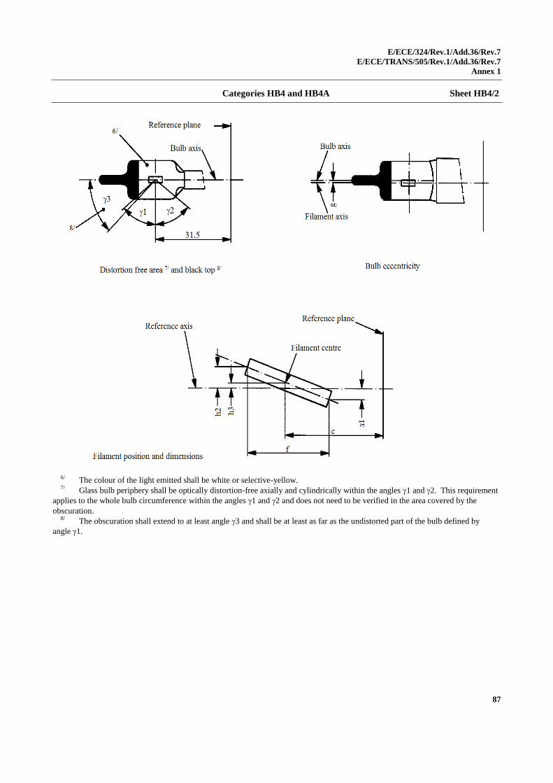
E/ECE/324/Rev.1/Add.36/Rev.7
E/ECE/TRANS/505/Rev.1/Add.36/Rev.7
Annex 1
87
Categories HB4 and HB4A Sheet HB4/2
6/ The colour of the light emitted shall be white or selective-yellow. 7/ Glass bulb periphery shall be optically distortion-free axially and cylindrically within the angles 1 and 2. This requirement
applies to the whole bulb circumference within the angles 1 and 2 and does not need to be verified in the area covered by the
obscuration. 8/ The obscuration shall extend to at least angle 3 and shall be at least as far as the undistorted part of the bulb defined by
angle 1.
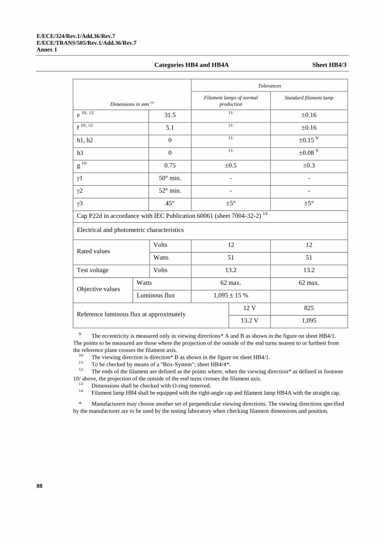
E/ECE/324/Rev.1/Add.36/Rev.7
E/ECE/TRANS/505/Rev.1/Add.36/Rev.7
Annex 1
88
Categories HB4 and HB4A Sheet HB4/3
Dimensions in mm 13/
Tolerances
Filament lamps of normal
production
Standard filament lamp
e 10/, 12/
31.5 11/
0.16
f 10/, 12/
5.1 11/
0.16
h1, h2 0 11/
0.15 9/
h3 0 11/
0.08 9/
g 10/
0.75 0.5 0.3
1 50° min. - -
2 52° min. - -
3 45° 5° 5°
Cap P22d in accordance with IEC Publication 60061 (sheet 7004-32-2) 14/
Electrical and photometric characteristics
Rated values Volts 12 12
Watts 51 51
Test voltage Volts 13.2 13.2
Objective values Watts 62 max. 62 max.
Luminous flux 1,095 15 %
Reference luminous flux at approximately 12 V 825
13.2 V 1,095
9/ The eccentricity is measured only in viewing directions* A and B as shown in the figure on sheet HB4/1.
The points to be measured are those where the projection of the outside of the end turns nearest to or furthest from
the reference plane crosses the filament axis. 10/ The viewing direction is direction* B as shown in the figure on sheet HB4/1. 11/ To be checked by means of a "Box-System"; sheet HB4/4*. 12/ The ends of the filament are defined as the points where, when the viewing direction* as defined in footnote
10/ above, the projection of the outside of the end turns crosses the filament axis. 13/ Dimensions shall be checked with O-ring removed. 14/ Filament lamp HB4 shall be equipped with the right-angle cap and filament lamp HB4A with the straight cap.
* Manufacturers may choose another set of perpendicular viewing directions. The viewing directions specified
by the manufacturer are to be used by the testing laboratory when checking filament dimensions and position.
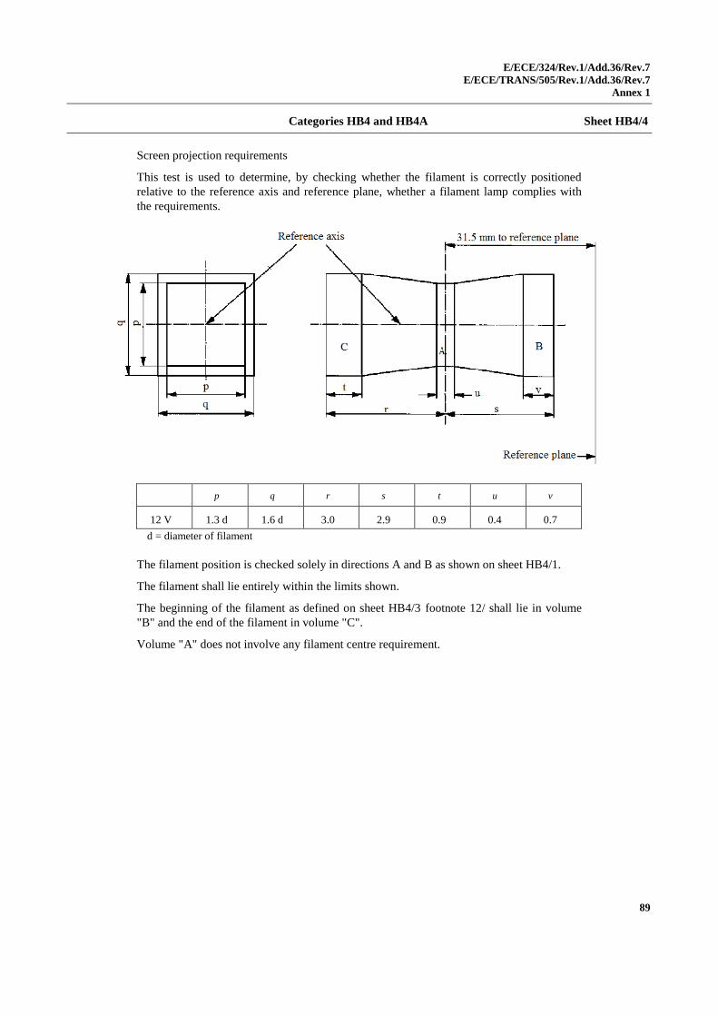
E/ECE/324/Rev.1/Add.36/Rev.7
E/ECE/TRANS/505/Rev.1/Add.36/Rev.7
Annex 1
89
Categories HB4 and HB4A Sheet HB4/4
Screen projection requirements
This test is used to determine, by checking whether the filament is correctly positioned
relative to the reference axis and reference plane, whether a filament lamp complies with
the requirements.
p q r s t u v
12 V 1.3 d 1.6 d 3.0 2.9 0.9 0.4 0.7
d = diameter of filament
The filament position is checked solely in directions A and B as shown on sheet HB4/1.
The filament shall lie entirely within the limits shown.
The beginning of the filament as defined on sheet HB4/3 footnote 12/ shall lie in volume
"B" and the end of the filament in volume "C".
Volume "A" does not involve any filament centre requirement.
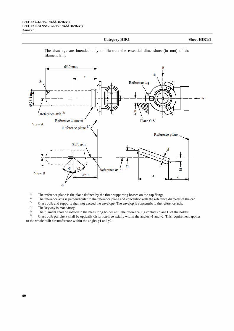
E/ECE/324/Rev.1/Add.36/Rev.7
E/ECE/TRANS/505/Rev.1/Add.36/Rev.7
Annex 1
90
Category HIR1 Sheet HIR1/1
The drawings are intended only to illustrate the essential dimensions (in mm) of the
filament lamp
1/ The reference plane is the plane defined by the three supporting bosses on the cap flange. 2/ The reference axis is perpendicular to the reference plane and concentric with the reference diameter of the cap. 3/ Glass bulb and supports shall not exceed the envelope. The envelop is concentric to the reference axis. 4/ The keyway is mandatory. 5/ The filament shall be rotated in the measuring holder until the reference lug contacts plane C of the holder. 6/ Glass bulb periphery shall be optically distortion-free axially within the angles 1 and 2. This requirement applies
to the whole bulb circumference within the angles 1 and 2.
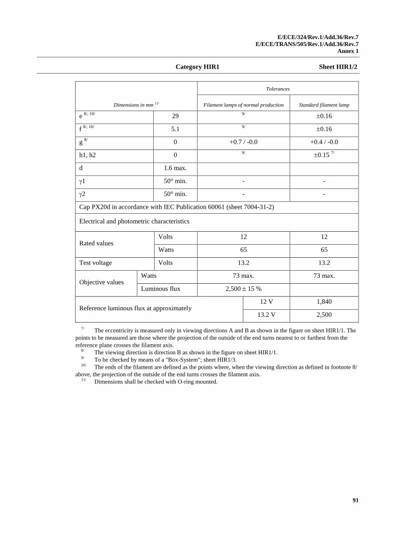
E/ECE/324/Rev.1/Add.36/Rev.7
E/ECE/TRANS/505/Rev.1/Add.36/Rev.7
Annex 1
91
Category HIR1 Sheet HIR1/2
Dimensions in mm 11/
Tolerances
Filament lamps of normal production Standard filament lamp
e 8/, 10/
29 9/
0.16
f 8/, 10/
5.1 9/
0.16
g 8/
0 +0.7 / -0.0 +0.4 / -0.0
h1, h2 0 9/
0.15 7/
d 1.6 max.
1 50° min. - -
2 50° min. - -
Cap PX20d in accordance with IEC Publication 60061 (sheet 7004-31-2)
Electrical and photometric characteristics
Rated values Volts 12 12
Watts 65 65
Test voltage Volts 13.2 13.2
Objective values Watts 73 max. 73 max.
Luminous flux 2,500 15 %
Reference luminous flux at approximately 12 V 1,840
13.2 V 2,500
7/ The eccentricity is measured only in viewing directions A and B as shown in the figure on sheet HIR1/1. The
points to be measured are those where the projection of the outside of the end turns nearest to or furthest from the
reference plane crosses the filament axis. 8/ The viewing direction is direction B as shown in the figure on sheet HIR1/1. 9/ To be checked by means of a "Box-System"; sheet HIR1/3. 10/ The ends of the filament are defined as the points where, when the viewing direction as defined in footnote 8/
above, the projection of the outside of the end turns crosses the filament axis. 11/ Dimensions shall be checked with O-ring mounted.
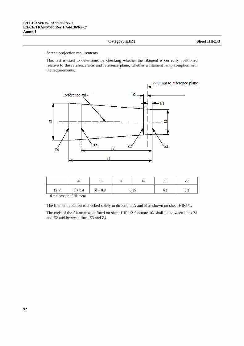
E/ECE/324/Rev.1/Add.36/Rev.7
E/ECE/TRANS/505/Rev.1/Add.36/Rev.7
Annex 1
92
Category HIR1 Sheet HIR1/3
Screen projection requirements
This test is used to determine, by checking whether the filament is correctly positioned
relative to the reference axis and reference plane, whether a filament lamp complies with
the requirements.
a1 a2 b1 b2 c1 c2
12 V d + 0.4 d + 0.8 0.35 6.1 5.2
d = diameter of filament
The filament position is checked solely in directions A and B as shown on sheet HIR1/1.
The ends of the filament as defined on sheet HIR1/2 footnote 10/ shall lie between lines Z1
and Z2 and between lines Z3 and Z4.
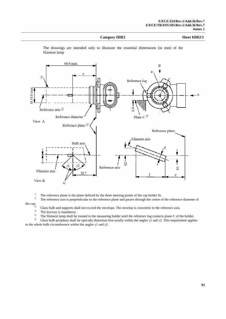
E/ECE/324/Rev.1/Add.36/Rev.7
E/ECE/TRANS/505/Rev.1/Add.36/Rev.7
Annex 1
93
Category HIR2 Sheet HIR2/1
The drawings are intended only to illustrate the essential dimensions (in mm) of the
filament lamp
1/ The reference plane is the plane defined by the three meeting points of the cap holder fit. 2/ The reference axis is perpendicular to the reference plane and passes through the centre of the reference diameter of
the cap. 3/ Glass bulb and supports shall not exceed the envelope. The envelop is concentric to the reference axis. 4/ The keyway is mandatory. 5/ The filament lamp shall be rotated in the measuring holder until the reference lug contacts plane C of the holder. 6/ Glass bulb periphery shall be optically distortion-free axially within the angles 1 and 2. This requirement applies
to the whole bulb circumference within the angles 1 and 2.
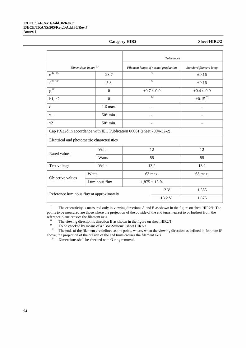
E/ECE/324/Rev.1/Add.36/Rev.7
E/ECE/TRANS/505/Rev.1/Add.36/Rev.7
Annex 1
94
Category HIR2 Sheet HIR2/2
Dimensions in mm 11/
Tolerances
Filament lamps of normal production Standard filament lamp
e 8/, 10/
28.7 9/
0.16
f 8/, 10/
5.3 9/
0.16
g 8/
0 +0.7 / -0.0 +0.4 / -0.0
h1, h2 0 9/
0.15 7/
d 1.6 max. - -
1 50° min. - -
2 50° min. - -
Cap PX22d in accordance with IEC Publication 60061 (sheet 7004-32-2)
Electrical and photometric characteristics
Rated values Volts 12 12
Watts 55 55
Test voltage Volts 13.2 13.2
Objective values Watts 63 max. 63 max.
Luminous flux 1,875 15 %
Reference luminous flux at approximately 12 V 1,355
13.2 V 1,875
7/ The eccentricity is measured only in viewing directions A and B as shown in the figure on sheet HIR2/1. The
points to be measured are those where the projection of the outside of the end turns nearest to or furthest from the
reference plane crosses the filament axis. 8/ The viewing direction is direction B as shown in the figure on sheet HIR2/1. 9/ To be checked by means of a "Box-System"; sheet HIR2/3. 10/ The ends of the filament are defined as the points where, when the viewing direction as defined in footnote 8/
above, the projection of the outside of the end turns crosses the filament axis. 11/ Dimensions shall be checked with O-ring removed.
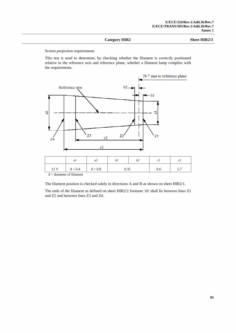
E/ECE/324/Rev.1/Add.36/Rev.7
E/ECE/TRANS/505/Rev.1/Add.36/Rev.7
Annex 1
95
Category HIR2 Sheet HIR2/3
Screen projection requirements
This test is used to determine, by checking whether the filament is correctly positioned
relative to the reference axis and reference plane, whether a filament lamp complies with
the requirements.
a1 a2 b1 b2 c1 c2
12 V d + 0.4 d + 0.8 0.35 6.6 5.7
d = diameter of filament
The filament position is checked solely in directions A and B as shown on sheet HIR2/1.
The ends of the filament as defined on sheet HIR2/2 footnote 10/ shall lie between lines Z1
and Z2 and between lines Z3 and Z4.
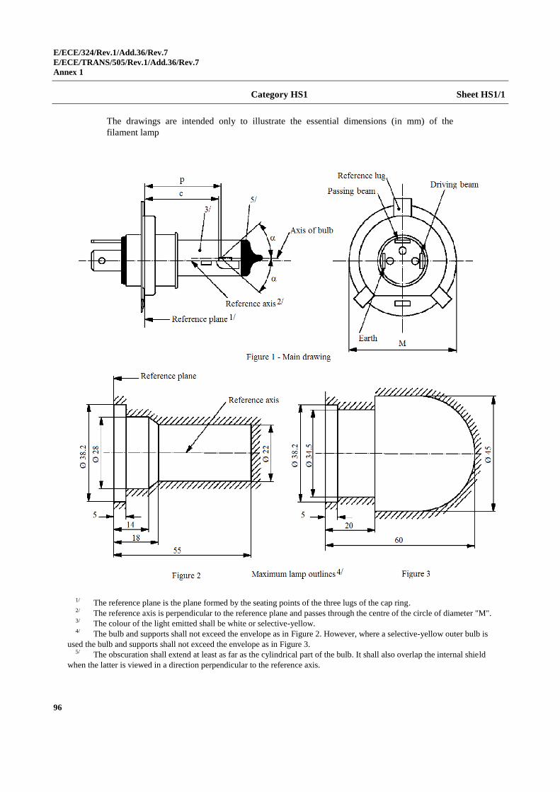
E/ECE/324/Rev.1/Add.36/Rev.7
E/ECE/TRANS/505/Rev.1/Add.36/Rev.7
Annex 1
96
Category HS1 Sheet HS1/1
The drawings are intended only to illustrate the essential dimensions (in mm) of the
filament lamp
1/ The reference plane is the plane formed by the seating points of the three lugs of the cap ring. 2/ The reference axis is perpendicular to the reference plane and passes through the centre of the circle of diameter "M". 3/ The colour of the light emitted shall be white or selective-yellow. 4/ The bulb and supports shall not exceed the envelope as in Figure 2. However, where a selective-yellow outer bulb is
used the bulb and supports shall not exceed the envelope as in Figure 3. 5/ The obscuration shall extend at least as far as the cylindrical part of the bulb. It shall also overlap the internal shield
when the latter is viewed in a direction perpendicular to the reference axis.
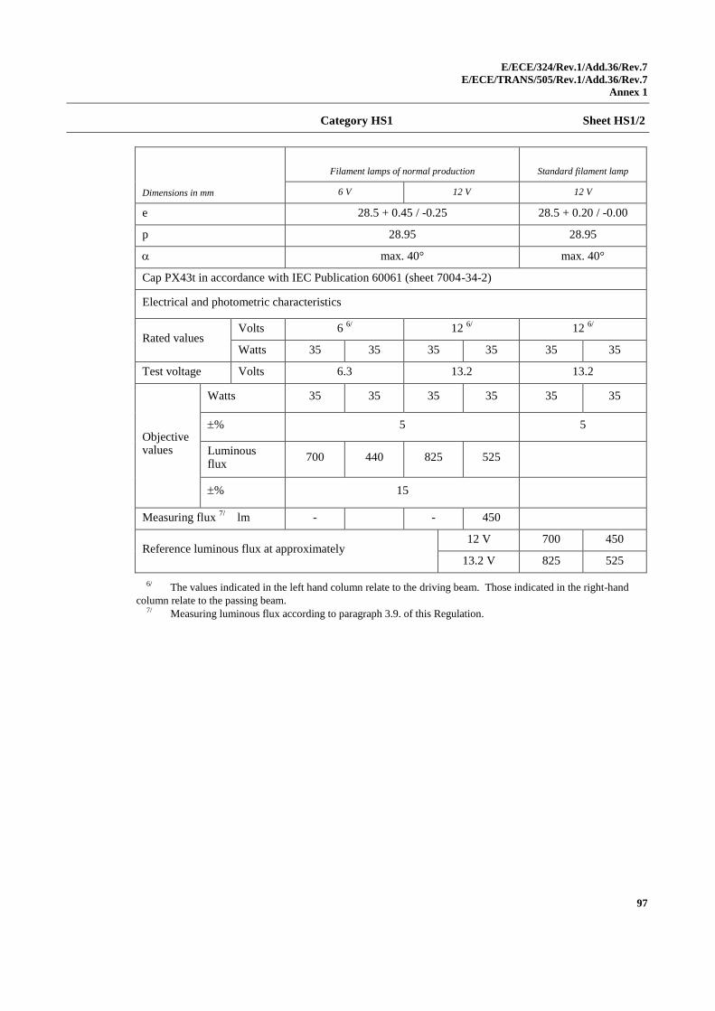
E/ECE/324/Rev.1/Add.36/Rev.7
E/ECE/TRANS/505/Rev.1/Add.36/Rev.7
Annex 1
97
Category HS1 Sheet HS1/2
Dimensions in mm
Filament lamps of normal production Standard filament lamp
6 V 12 V 12 V
e 28.5 + 0.45 / -0.25 28.5 + 0.20 / -0.00
p 28.95 28.95
max. 40° max. 40°
Cap PX43t in accordance with IEC Publication 60061 (sheet 7004-34-2)
Electrical and photometric characteristics
Rated values Volts 6
6/ 12
6/ 12
6/
Watts 35 35 35 35 35 35
Test voltage Volts 6.3 13.2 13.2
Objective values
Watts 35 35 35 35 35 35
% 5 5
Luminous flux
700 440 825 525
% 15
Measuring flux 7/
lm - - 450
Reference luminous flux at approximately 12 V 700 450
13.2 V 825 525
6/ The values indicated in the left hand column relate to the driving beam. Those indicated in the right-hand
column relate to the passing beam. 7/ Measuring luminous flux according to paragraph 3.9. of this Regulation.
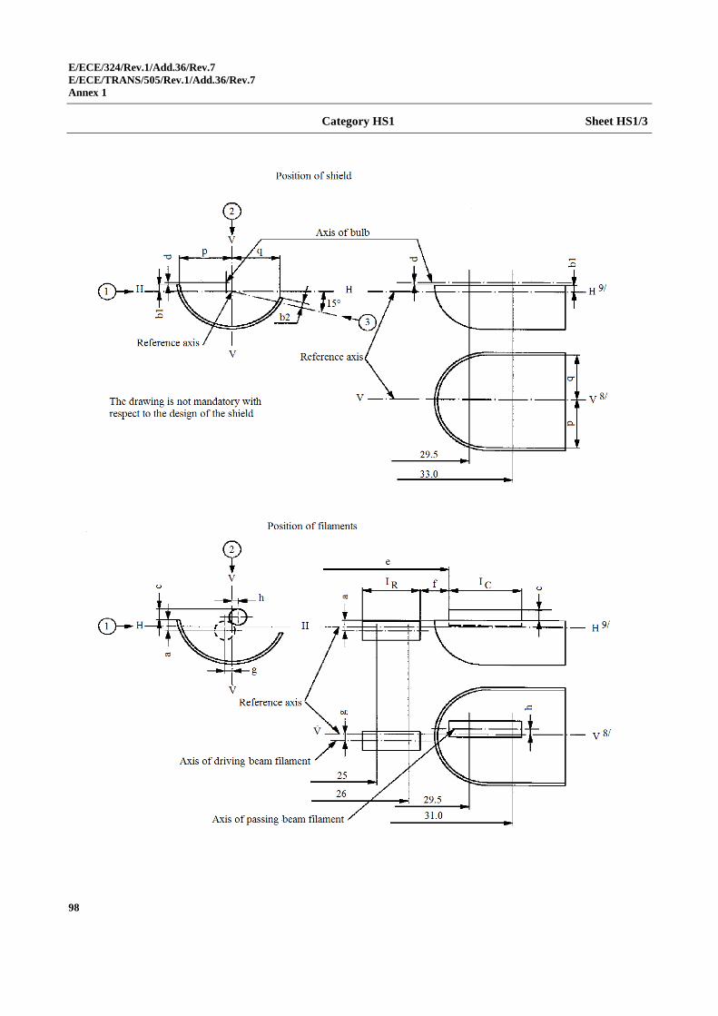
E/ECE/324/Rev.1/Add.36/Rev.7
E/ECE/TRANS/505/Rev.1/Add.36/Rev.7
Annex 1
98
Category HS1 Sheet HS1/3
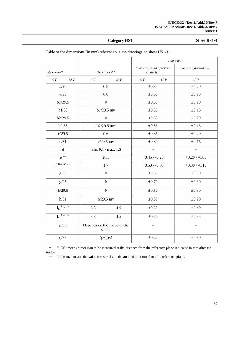
E/ECE/324/Rev.1/Add.36/Rev.7
E/ECE/TRANS/505/Rev.1/Add.36/Rev.7
Annex 1
99
Category HS1 Sheet HS1/4
Table of the dimensions (in mm) referred to in the drawings on sheet HS1/3
Reference* Dimensions**
Tolerance
Filaments lamps of normal
production
Standard filament lamp
6 V 12 V 6 V 12 V 6 V 12 V 12 V
a/26 0.8 0.35 0.20
a/25 0.8 0.55 0.20
b1/29.5 0 0.35 0.20
b1/33 b1/29.5 mv 0.35 0.15
b2/29.5 0 0.35 0.20
b2/33 b2/29.5 mv 0.35 0.15
c/29.5 0.6 0.35 0.20
c/31 c/29.5 mv 0.30 0.15
d min. 0.1 / max. 1.5 - -
e 13/
28.5 +0.45 / -0.25 +0.20 / -0.00
f 11/, 12/, 13/
1.7 +0.50 / -0.30 +0.30 / -0.10
g/26 0 0.50 0.30
g/25 0 0.70 0.30
h/29.5 0 0.50 0.30
h/31 h/29.5 mv 0.30 0.20
lR 11/, 14/
3.5 4.0 0.80 0.40
lC 11/, 12/
3.3 4.5 0.80 0.35
p/33 Depends on the shape of the shield
- -
q/33 (p+q)/2 0.60 0.30
* "../26" means dimension to be measured at the distance from the reference plane indicated in mm after the
stroke.
** "29.5 mv" means the value measured at a distance of 29.5 mm from the reference plane.
E/ECE/324/Rev.1/Add.36/Rev.7
E/ECE/TRANS/505/Rev.1/Add.36/Rev.7
Annex 1
100
Category HS1 Sheet HS1/5
8/ Plane V-V is the plane perpendicular to the reference plane and passing through the reference
axis and through the intersection of the circle of diameter "M" with the axis of the reference lug. 9/ Plane H-H is the plane perpendicular to both the reference plane and plane V-V and passing
through the reference axis. 10/ (Blank). 11/ The end turns of the filament are defined as being the first luminous turn and the last
luminous turn that are at substantially the correct helix angle. For coiled-coil filaments, the turns are
defined by the envelope of the primary coil. 12/ For the passing beam filament, the points to be measured are the intersections, seen in direction 1 ,
of the lateral edge of the shield with the outside of the end turns defined under footnote 11/. 13/ "e" denotes the distance from the reference plane to the beginning of the passing beam
filament as defined above. 14/ For the driving beam filament the points to be measured are the intersections, seen in
direction 1 , of a plane, parallel to plane H-H and situated at a distance of 0.8 mm below it, with the
end turns defined under footnote 11/.
Additional explanations to sheet HS1/3
The dimensions below are measured in three directions:
1 For dimensions a, b1, c, d, e, f, IR and IC;
2 For dimensions g, h, p and q;
3 For dimension b2.
Dimensions p and q are measured in planes parallel to and 33 mm away from the reference
plane.
Dimensions b1 and b2 are measured in planes parallel to and 29.5 mm and 33 mm away
from the reference plane.
Dimensions a and g are measured in planes parallel to and 25.0 mm and 26.0 mm away
from the reference plane.
Dimensions c and h are measured in planes parallel to and 29.5 mm and 31 mm away from
the reference plane.
Note: For the method of measurement, see Appendix E of IEC Publication 60809.
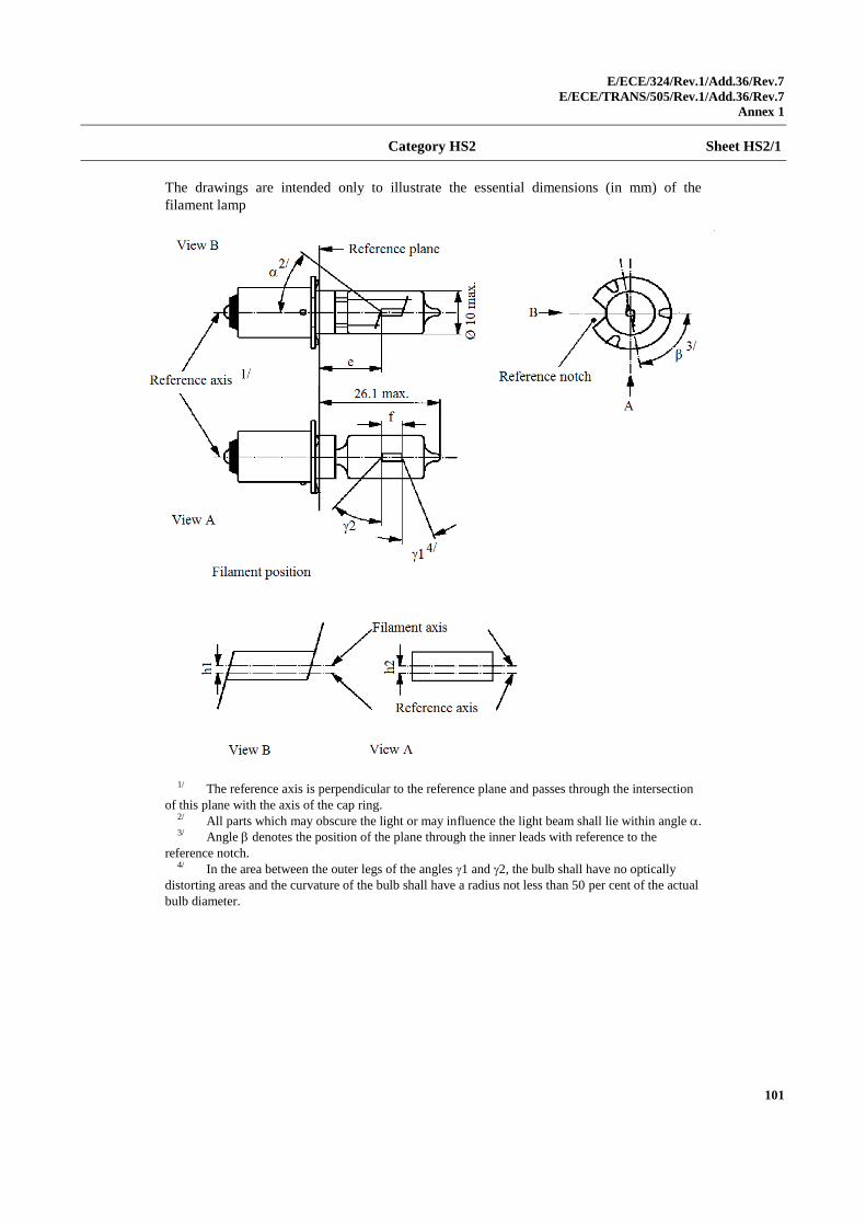
E/ECE/324/Rev.1/Add.36/Rev.7
E/ECE/TRANS/505/Rev.1/Add.36/Rev.7
Annex 1
101
Category HS2 Sheet HS2/1
The drawings are intended only to illustrate the essential dimensions (in mm) of the
filament lamp
1/ The reference axis is perpendicular to the reference plane and passes through the intersection
of this plane with the axis of the cap ring. 2/ All parts which may obscure the light or may influence the light beam shall lie within angle . 3/ Angle denotes the position of the plane through the inner leads with reference to the
reference notch. 4/ In the area between the outer legs of the angles 1 and 2, the bulb shall have no optically
distorting areas and the curvature of the bulb shall have a radius not less than 50 per cent of the actual
bulb diameter.
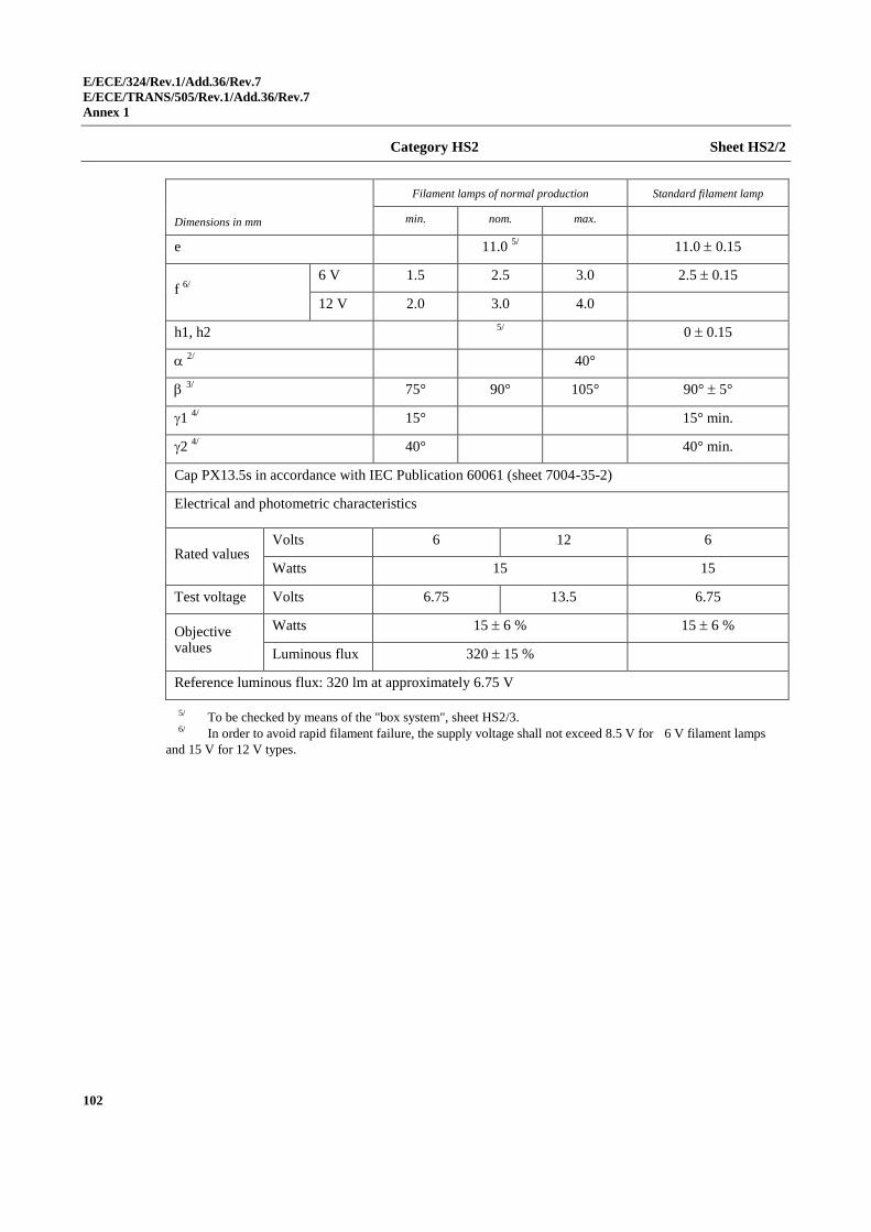
E/ECE/324/Rev.1/Add.36/Rev.7
E/ECE/TRANS/505/Rev.1/Add.36/Rev.7
Annex 1
102
Category HS2 Sheet HS2/2
Dimensions in mm
Filament lamps of normal production Standard filament lamp
min. nom. max.
e 11.0 5/ 11.0 0.15
f 6/
6 V 1.5 2.5 3.0 2.5 0.15
12 V 2.0 3.0 4.0
h1, h2 5/
0 0.15
2/
40°
3/ 75° 90° 105° 90° 5°
1 4/
15° 15° min.
2 4/
40° 40° min.
Cap PX13.5s in accordance with IEC Publication 60061 (sheet 7004-35-2)
Electrical and photometric characteristics
Rated values Volts 6 12 6
Watts 15 15
Test voltage Volts 6.75 13.5 6.75
Objective values
Watts 15 6 % 15 6 %
Luminous flux 320 15 %
Reference luminous flux: 320 lm at approximately 6.75 V
5/ To be checked by means of the "box system", sheet HS2/3. 6/ In order to avoid rapid filament failure, the supply voltage shall not exceed 8.5 V for 6 V filament lamps
and 15 V for 12 V types.
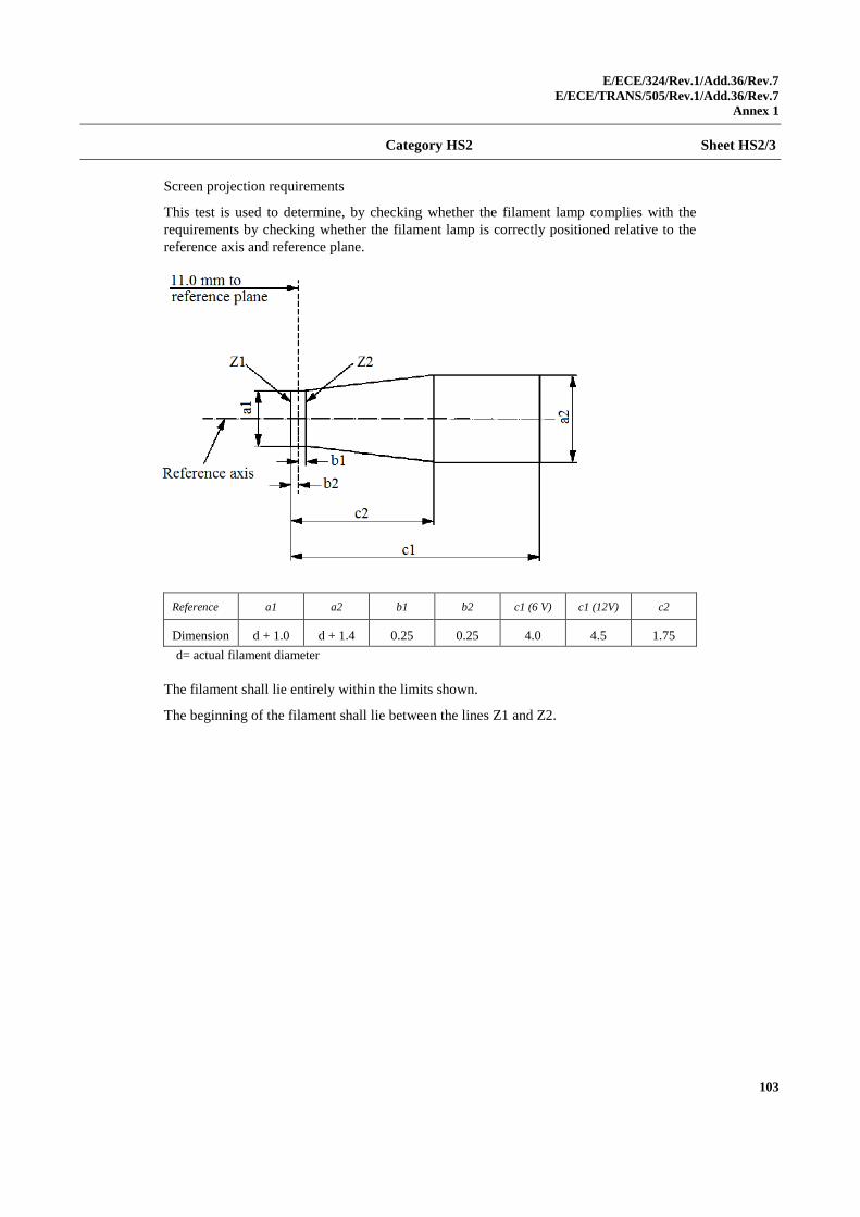
E/ECE/324/Rev.1/Add.36/Rev.7
E/ECE/TRANS/505/Rev.1/Add.36/Rev.7
Annex 1
103
Category HS2 Sheet HS2/3
Screen projection requirements
This test is used to determine, by checking whether the filament lamp complies with the
requirements by checking whether the filament lamp is correctly positioned relative to the
reference axis and reference plane.
Reference a1 a2 b1 b2 c1 (6 V) c1 (12V) c2
Dimension d + 1.0 d + 1.4 0.25 0.25 4.0 4.5 1.75
d= actual filament diameter
The filament shall lie entirely within the limits shown.
The beginning of the filament shall lie between the lines Z1 and Z2.
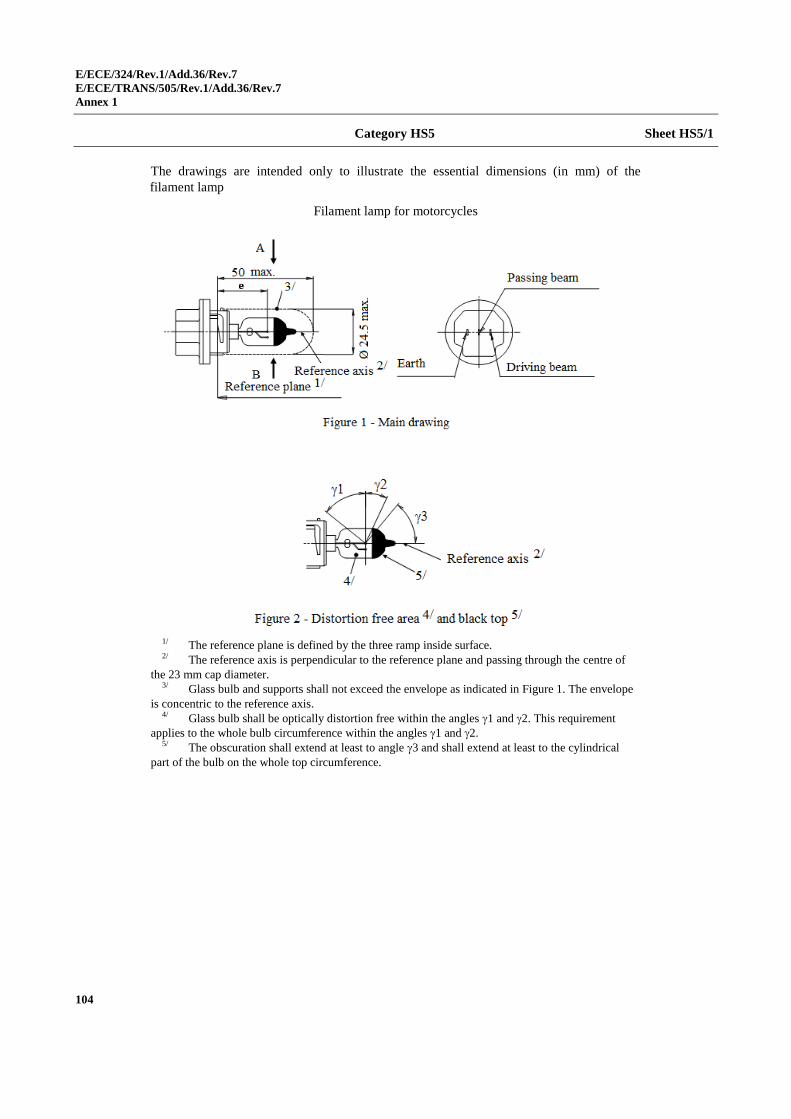
E/ECE/324/Rev.1/Add.36/Rev.7
E/ECE/TRANS/505/Rev.1/Add.36/Rev.7
Annex 1
104
Category HS5 Sheet HS5/1
The drawings are intended only to illustrate the essential dimensions (in mm) of the
filament lamp
Filament lamp for motorcycles
1/ The reference plane is defined by the three ramp inside surface. 2/ The reference axis is perpendicular to the reference plane and passing through the centre of
the 23 mm cap diameter. 3/ Glass bulb and supports shall not exceed the envelope as indicated in Figure 1. The envelope
is concentric to the reference axis. 4/ Glass bulb shall be optically distortion free within the angles 1 and 2. This requirement
applies to the whole bulb circumference within the angles 1 and 2. 5/ The obscuration shall extend at least to angle 3 and shall extend at least to the cylindrical
part of the bulb on the whole top circumference.
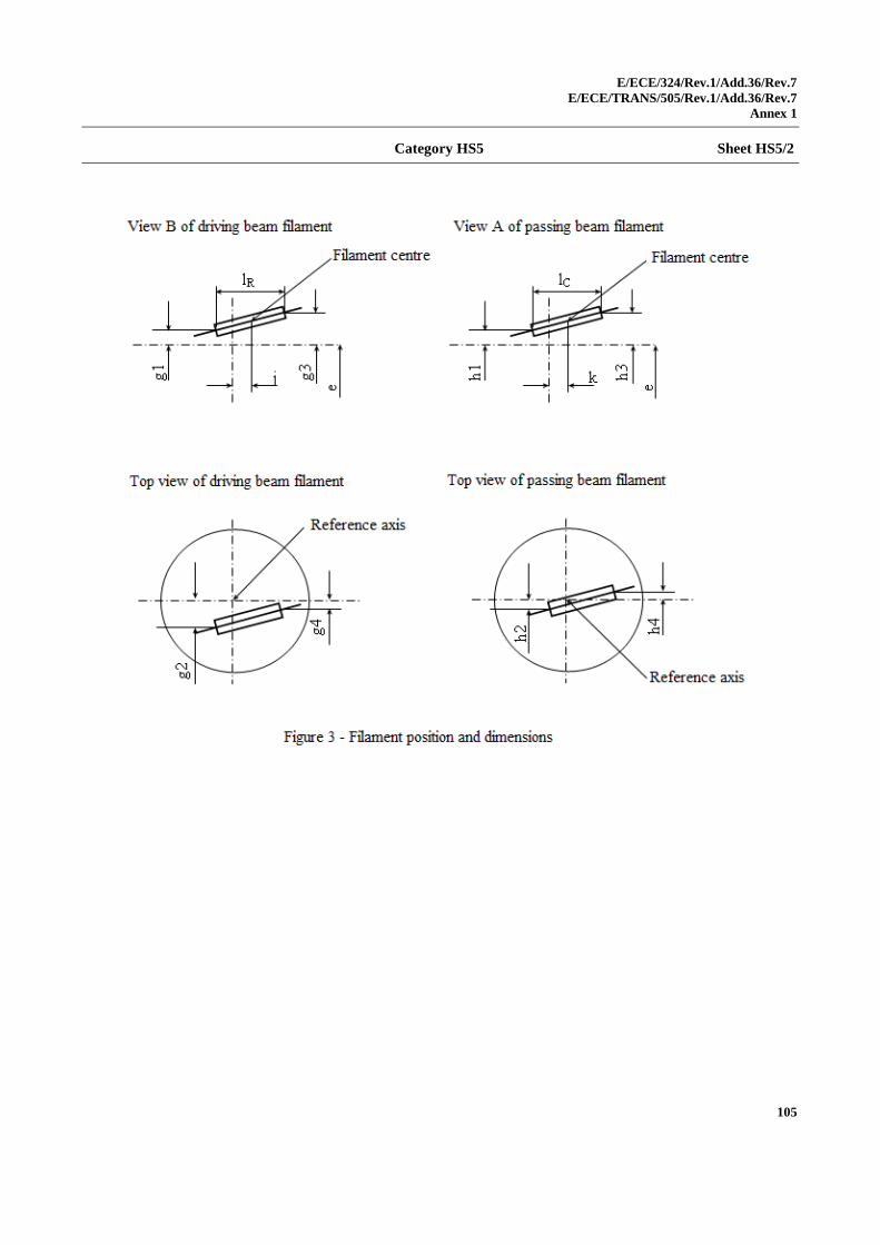
E/ECE/324/Rev.1/Add.36/Rev.7
E/ECE/TRANS/505/Rev.1/Add.36/Rev.7
Annex 1
105
Category HS5 Sheet HS5/2
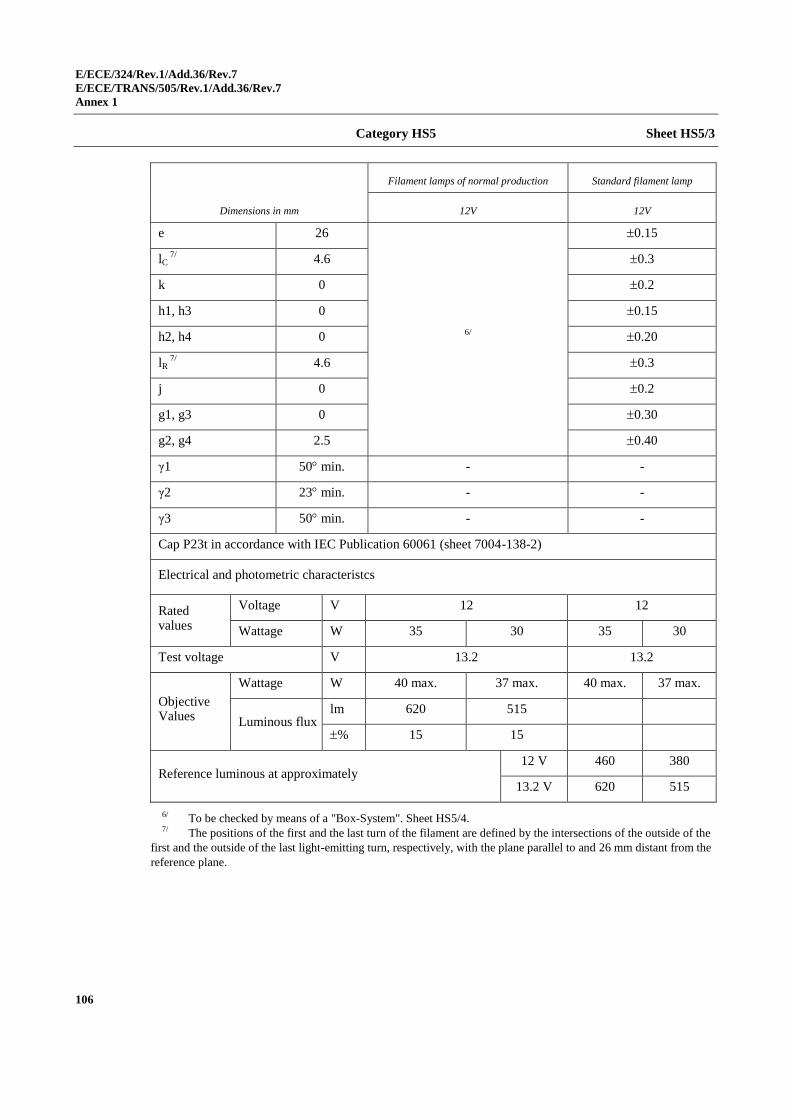
E/ECE/324/Rev.1/Add.36/Rev.7
E/ECE/TRANS/505/Rev.1/Add.36/Rev.7
Annex 1
106
Category HS5 Sheet HS5/3
Dimensions in mm
Filament lamps of normal production Standard filament lamp
12V 12V
e 26
6/
0.15
lC 7/
4.6 0.3
k 0 0.2
h1, h3 0 0.15
h2, h4 0 0.20
lR 7/
4.6 0.3
j 0 0.2
g1, g3 0 0.30
g2, g4 2.5 0.40
γ1 50 min. - -
γ2 23 min. - -
γ3 50 min. - -
Cap P23t in accordance with IEC Publication 60061 (sheet 7004-138-2)
Electrical and photometric characteristcs
Rated values
Voltage V 12 12
Wattage W 35 30 35 30
Test voltage V 13.2 13.2
Objective Values
Wattage W 40 max. 37 max. 40 max. 37 max.
Luminous flux lm 620 515
% 15 15
Reference luminous at approximately 12 V 460 380
13.2 V 620 515
6/ To be checked by means of a "Box-System". Sheet HS5/4. 7/ The positions of the first and the last turn of the filament are defined by the intersections of the outside of the
first and the outside of the last light-emitting turn, respectively, with the plane parallel to and 26 mm distant from the
reference plane.
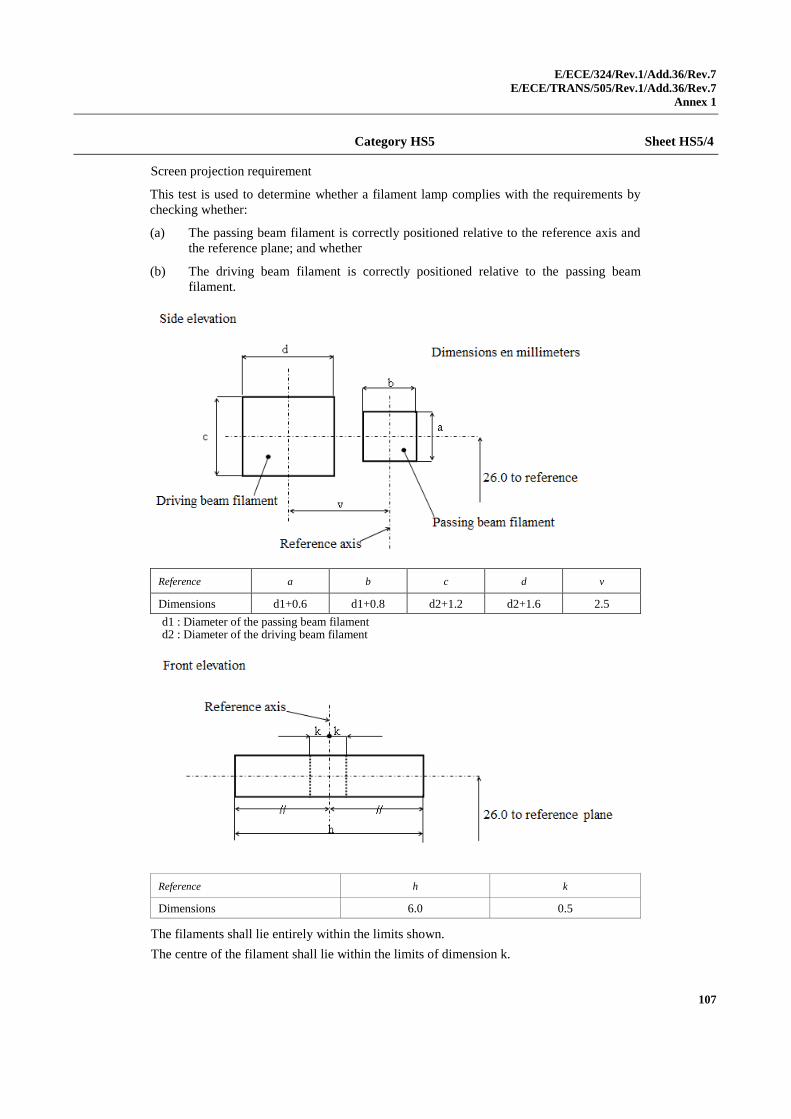
E/ECE/324/Rev.1/Add.36/Rev.7
E/ECE/TRANS/505/Rev.1/Add.36/Rev.7
Annex 1
107
Category HS5 Sheet HS5/4
Screen projection requirement
This test is used to determine whether a filament lamp complies with the requirements by
checking whether:
(a) The passing beam filament is correctly positioned relative to the reference axis and
the reference plane; and whether
(b) The driving beam filament is correctly positioned relative to the passing beam
filament.
Reference a b c d v
Dimensions d1+0.6 d1+0.8 d2+1.2 d2+1.6 2.5
d1 : Diameter of the passing beam filament d2 : Diameter of the driving beam filament
Reference h k
Dimensions 6.0 0.5
The filaments shall lie entirely within the limits shown.
The centre of the filament shall lie within the limits of dimension k.
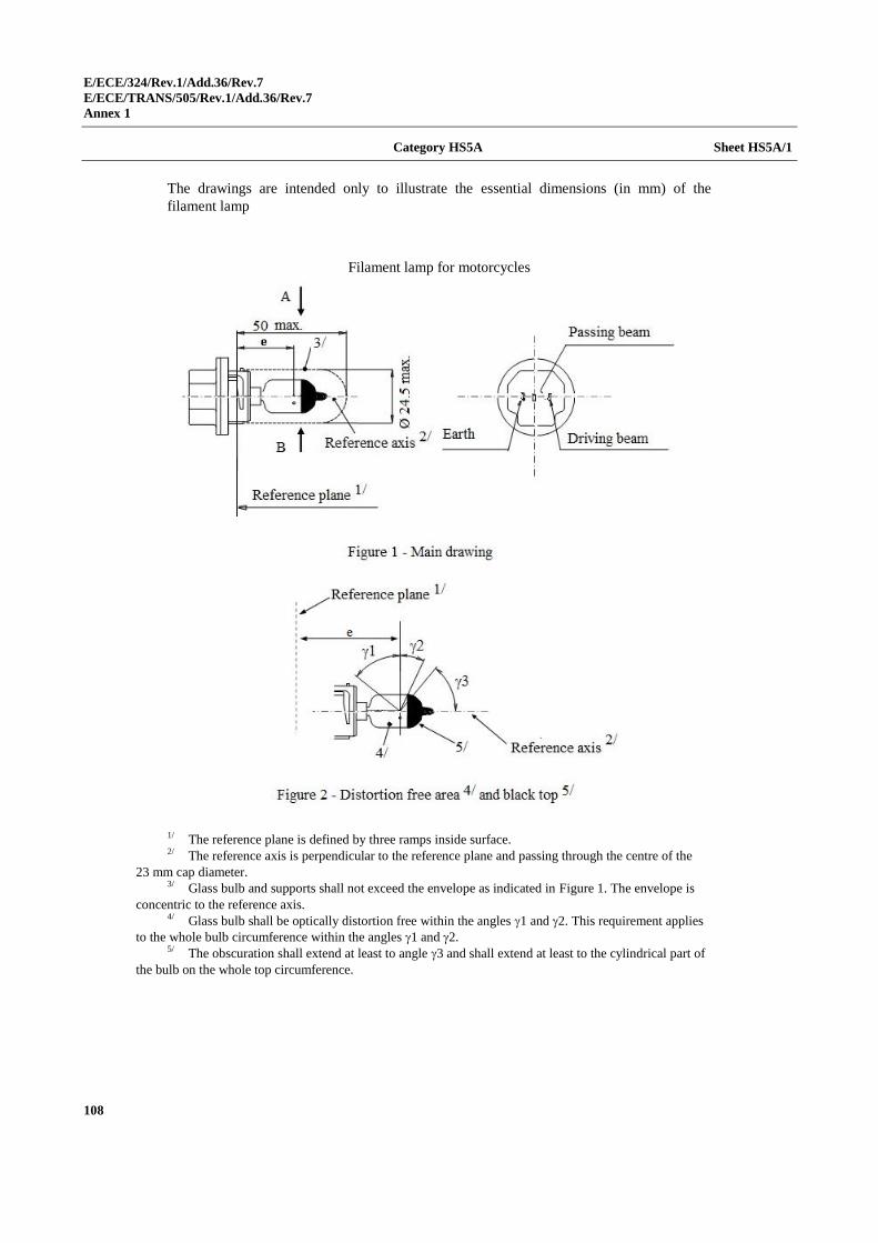
E/ECE/324/Rev.1/Add.36/Rev.7
E/ECE/TRANS/505/Rev.1/Add.36/Rev.7
Annex 1
108
Category HS5A Sheet HS5A/1
The drawings are intended only to illustrate the essential dimensions (in mm) of the
filament lamp
Filament lamp for motorcycles
1/ The reference plane is defined by three ramps inside surface. 2/ The reference axis is perpendicular to the reference plane and passing through the centre of the
23 mm cap diameter. 3/ Glass bulb and supports shall not exceed the envelope as indicated in Figure 1. The envelope is
concentric to the reference axis. 4/ Glass bulb shall be optically distortion free within the angles 1 and 2. This requirement applies
to the whole bulb circumference within the angles 1 and 2. 5/ The obscuration shall extend at least to angle 3 and shall extend at least to the cylindrical part of
the bulb on the whole top circumference.
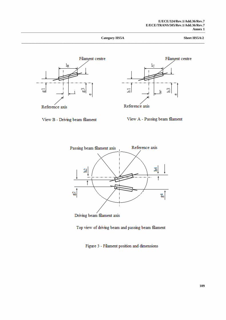
E/ECE/324/Rev.1/Add.36/Rev.7
E/ECE/TRANS/505/Rev.1/Add.36/Rev.7
Annex 1
109
Category HS5A Sheet HS5A/2
___________________________________________________________________________________________________________
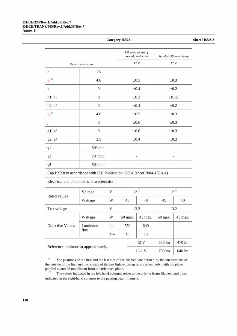
E/ECE/324/Rev.1/Add.36/Rev.7
E/ECE/TRANS/505/Rev.1/Add.36/Rev.7
Annex 1
110
Category HS5A Sheet HS5A/3
Dimensions in mm
Filament lamps of
normal production Standard filament lamp
12 V 12 V
e 26 - -
lC 6/
4.6 0.5 0.3
k 0 0.4 0.2
h1, h3 0 0.3 0.15
h2, h4 0 0.4 0.2
lR 6/
4.6 0.5 0.3
j 0 0.6 0.3
g1, g3 0 0.6 0.3
g2, g4 2.5 0.4 0.2
γ1 50 min. - -
γ2 23 min. - -
γ3 50 min. - -
Cap PX23t in accordance with IEC Publication 60061 (sheet 7004-138A-1)
Electrical and photometric characteristics
Rated values Voltage V 12
7/ 12
7/
Wattage W 45 40 45 40
Test voltage V 13.2 13.2
Objective Values
Wattage W 50 max. 45 max. 50 max. 45 max.
Luminous flux
lm 750 640
% 15 15
Reference luminous at approximately 12 V 550 lm 470 lm
13.2 V 750 lm 640 lm
6/ The positions of the first and the last turn of the filament are defined by the intersections of
the outside of the first and the outside of the last light-emitting turn, respectively, with the plane
parallel to and 26 mm distant from the reference plane. 7/
The values indicated in the left-hand columns relate to the driving beam filament and those
indicated in the right-hand columns to the passing beam filament.
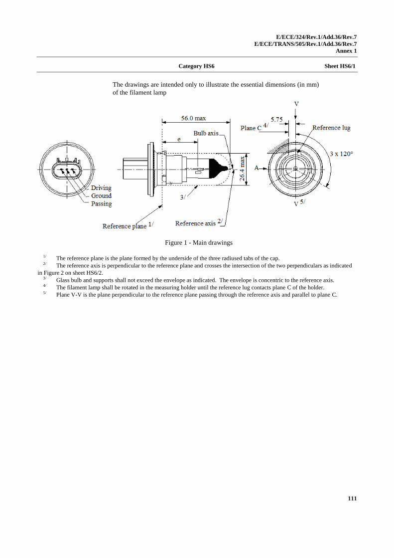
E/ECE/324/Rev.1/Add.36/Rev.7
E/ECE/TRANS/505/Rev.1/Add.36/Rev.7
Annex 1
111
Category HS6 Sheet HS6/1
The drawings are intended only to illustrate the essential dimensions (in mm)
of the filament lamp
Figure 1 - Main drawings
1/ The reference plane is the plane formed by the underside of the three radiused tabs of the cap. 2/ The reference axis is perpendicular to the reference plane and crosses the intersection of the two perpendiculars as indicated
in Figure 2 on sheet HS6/2. 3/ Glass bulb and supports shall not exceed the envelope as indicated. The envelope is concentric to the reference axis. 4/ The filament lamp shall be rotated in the measuring holder until the reference lug contacts plane C of the holder. 5/ Plane V-V is the plane perpendicular to the reference plane passing through the reference axis and parallel to plane C.
3/
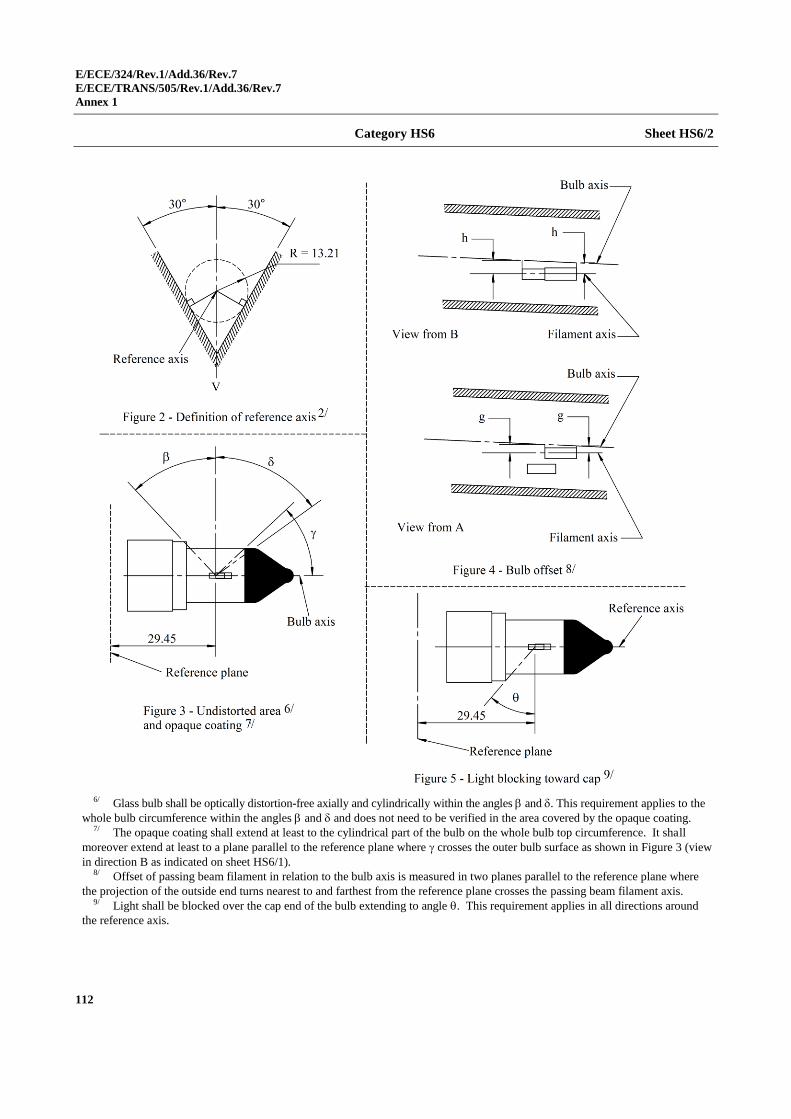
E/ECE/324/Rev.1/Add.36/Rev.7
E/ECE/TRANS/505/Rev.1/Add.36/Rev.7
Annex 1
112
Category HS6 Sheet HS6/2
6/ Glass bulb shall be optically distortion-free axially and cylindrically within the angles and . This requirement applies to the
whole bulb circumference within the angles and and does not need to be verified in the area covered by the opaque coating. 7/ The opaque coating shall extend at least to the cylindrical part of the bulb on the whole bulb top circumference. It shall
moreover extend at least to a plane parallel to the reference plane where crosses the outer bulb surface as shown in Figure 3 (view
in direction B as indicated on sheet HS6/1). 8/ Offset of passing beam filament in relation to the bulb axis is measured in two planes parallel to the reference plane where
the projection of the outside end turns nearest to and farthest from the reference plane crosses the passing beam filament axis. 9/ Light shall be blocked over the cap end of the bulb extending to angle . This requirement applies in all directions around
the reference axis.
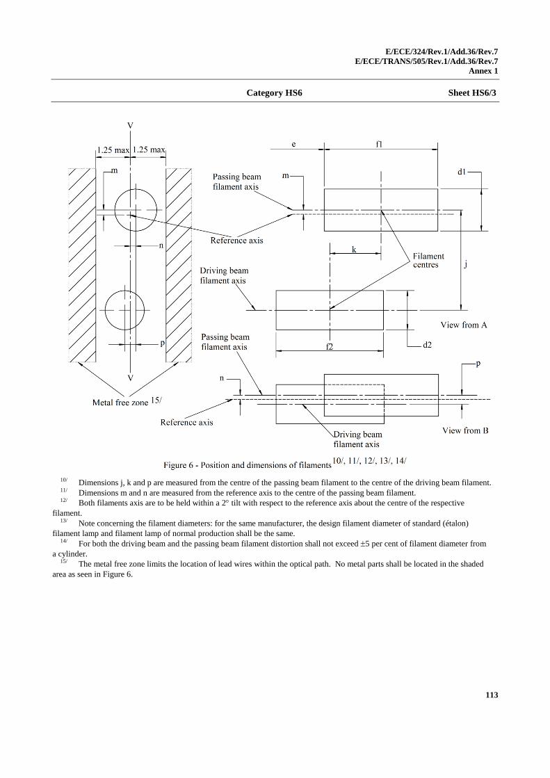
E/ECE/324/Rev.1/Add.36/Rev.7
E/ECE/TRANS/505/Rev.1/Add.36/Rev.7
Annex 1
113
Category HS6 Sheet HS6/3
10/ Dimensions j, k and p are measured from the centre of the passing beam filament to the centre of the driving beam filament. 11/ Dimensions m and n are measured from the reference axis to the centre of the passing beam filament. 12/ Both filaments axis are to be held within a 2 tilt with respect to the reference axis about the centre of the respective
filament. 13/ Note concerning the filament diameters: for the same manufacturer, the design filament diameter of standard (étalon)
filament lamp and filament lamp of normal production shall be the same. 14/ For both the driving beam and the passing beam filament distortion shall not exceed 5 per cent of filament diameter from
a cylinder. 15/ The metal free zone limits the location of lead wires within the optical path. No metal parts shall be located in the shaded
area as seen in Figure 6.
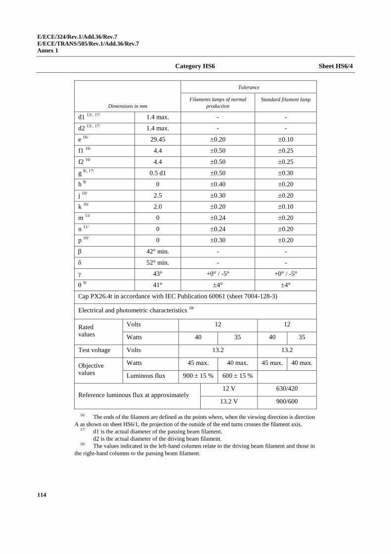
E/ECE/324/Rev.1/Add.36/Rev.7
E/ECE/TRANS/505/Rev.1/Add.36/Rev.7
Annex 1
114
Category HS6 Sheet HS6/4
Dimensions in mm
Tolerance
Filaments lamps of normal
production
Standard filament lamp
d1 13/,
17/
1.4 max. - -
d2 13/,
17/
1.4 max. - -
e 16/
29.45 0.20 0.10
f1 16/
4.4 0.50 0.25
f2 16/
4.4 0.50 0.25
g 8/, 17/
0.5 d1 0.50 0.30
h 8/
0 0.40 0.20
j 10/
2.5 0.30 0.20
k 10/
2.0 0.20 0.10
m 11/
0 0.24 0.20
n 11/
0 0.24 0.20
p 10/
0 0.30 0.20
42° min. - -
52° min. - -
43° +0° / -5° +0° / -5°
9/
41° 4° 4°
Cap PX26.4t in accordance with IEC Publication 60061 (sheet 7004-128-3)
Electrical and photometric characteristics 18/
Rated values
Volts 12 12
Watts 40 35 40 35
Test voltage Volts 13.2 13.2
Objective values
Watts 45 max. 40 max. 45 max. 40 max.
Luminous flux 900 15 % 600 15 %
Reference luminous flux at approximately 12 V 630/420
13.2 V 900/600
16/ The ends of the filament are defined as the points where, when the viewing direction is direction
A as shown on sheet HS6/1, the projection of the outside of the end turns crosses the filament axis. 17/ d1 is the actual diameter of the passing beam filament.
d2 is the actual diameter of the driving beam filament. 18/ The values indicated in the left-hand columns relate to the driving beam filament and those in
the right-hand columns to the passing beam filament.
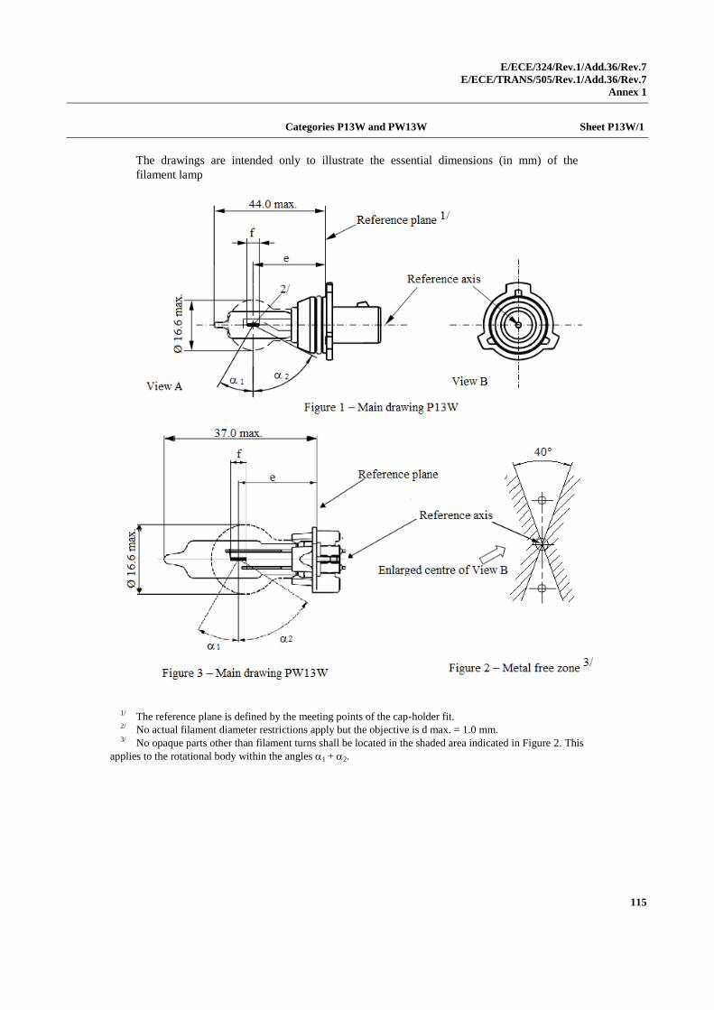
E/ECE/324/Rev.1/Add.36/Rev.7
E/ECE/TRANS/505/Rev.1/Add.36/Rev.7
Annex 1
115
Categories P13W and PW13W Sheet P13W/1
The drawings are intended only to illustrate the essential dimensions (in mm) of the
filament lamp
1/ The reference plane is defined by the meeting points of the cap-holder fit. 2/ No actual filament diameter restrictions apply but the objective is d max. = 1.0 mm. 3/ No opaque parts other than filament turns shall be located in the shaded area indicated in Figure 2. This
applies to the rotational body within the angles 1 + 2.
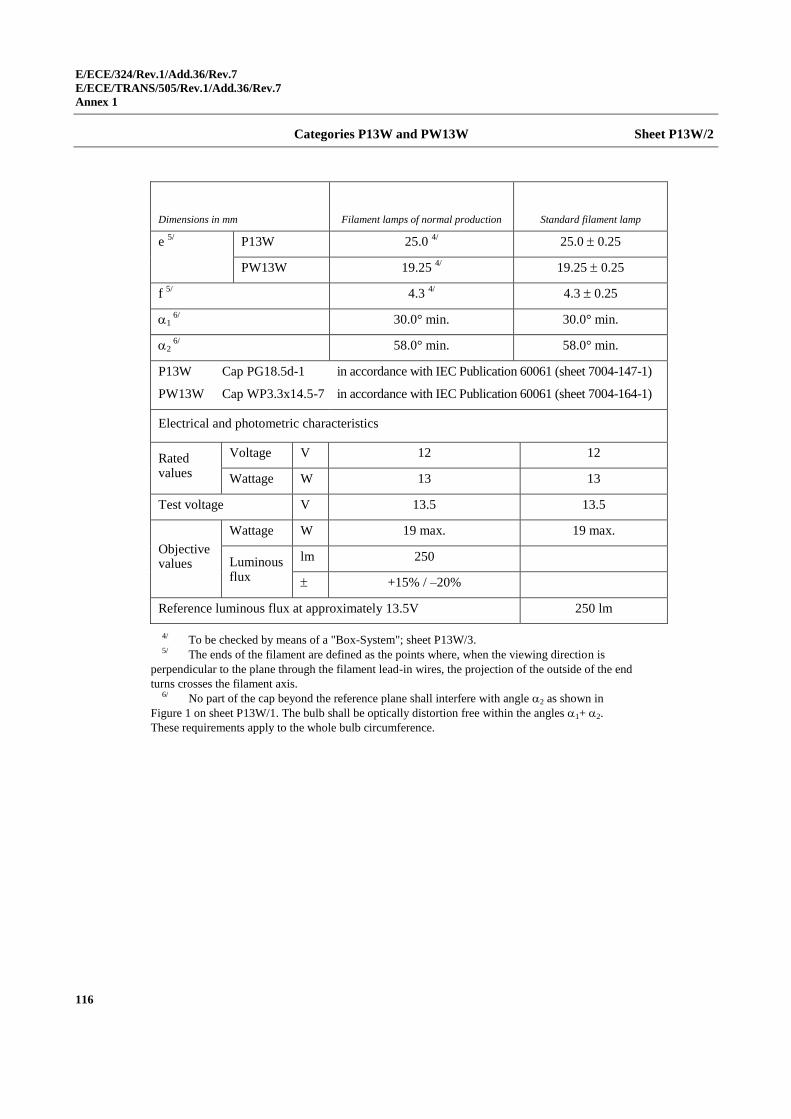
E/ECE/324/Rev.1/Add.36/Rev.7
E/ECE/TRANS/505/Rev.1/Add.36/Rev.7
Annex 1
116
Categories P13W and PW13W Sheet P13W/2
Dimensions in mm Filament lamps of normal production Standard filament lamp
e 5/
P13W 25.0 4/ 25.0 0.25
PW13W 19.25 4/ 19.25 0.25
f 5/
4.3 4/ 4.3 0.25
1 6/
30.0° min.
30.0° min.
2 6/
58.0° min.
58.0° min.
P13W Cap PG18.5d-1
PW13W Cap WP3.3x14.5-7
in accordance with IEC Publication 60061 (sheet 7004-147-1)
in accordance with IEC Publication 60061 (sheet 7004-164-1)
Electrical and photometric characteristics
Rated values
Voltage V 12 12
Wattage W 13 13
Test voltage V 13.5 13.5
Objective values
Wattage W 19 max. 19 max.
Luminous flux
lm 250
+15% / –20%
Reference luminous flux at approximately 13.5V 250 lm
4/ To be checked by means of a "Box-System"; sheet P13W/3. 5/ The ends of the filament are defined as the points where, when the viewing direction is
perpendicular to the plane through the filament lead-in wires, the projection of the outside of the end
turns crosses the filament axis. 6/ No part of the cap beyond the reference plane shall interfere with angle 2 as shown in
Figure 1 on sheet P13W/1. The bulb shall be optically distortion free within the angles 1+ 2.
These requirements apply to the whole bulb circumference.
E/ECE/324/Rev.1/Add.36/Rev.7
E/ECE/TRANS/505/Rev.1/Add.36/Rev.7
Annex 1
117
Categories P13W and PW13W Sheet P13W/3
Screen projection requirements
This test is used to determine, by checking whether the filament is correctly positioned
relative to the reference axis and reference plane, whether a filament lamp complies with
the requirements.
p q u1,u2 r,s t,v
Filament lamps of normal production 1.7 1.9 0.3 2.6 0.9
Standard filament lamps 1.5 1.7 0.25 2.45 0.6
The filament position is checked in two mutually perpendicular planes, one of them being
the plane through the lead-in wires.
The ends of the filament as defined on sheet P13W/2, footnote 4/, shall lie between Z1 and
Z2 and between the lines Z3 and Z4.
The filament shall lie entirely within the limits shown.
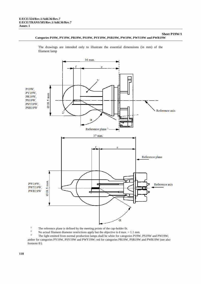
E/ECE/324/Rev.1/Add.36/Rev.7
E/ECE/TRANS/505/Rev.1/Add.36/Rev.7
Annex 1
118
Sheet P19W/1 Categories P19W, PY19W, PR19W, PS19W, PSY19W, PSR19W, PW19W, PWY19W and PWR19W
The drawings are intended only to illustrate the essential dimensions (in mm) of the
filament lamp
1/ The reference plane is defined by the meeting points of the cap-holder fit. 2/ No actual filament diameter restrictions apply but the objective is d max. = 1.1 mm. 3/ The light emitted from normal production lamps shall be white for categories P19W, PS19W and PW19W;
amber for categories PY19W, PSY19W and PWY19W; red for categories PR19W, PSR19W and PWR19W (see also
footnote 8/).
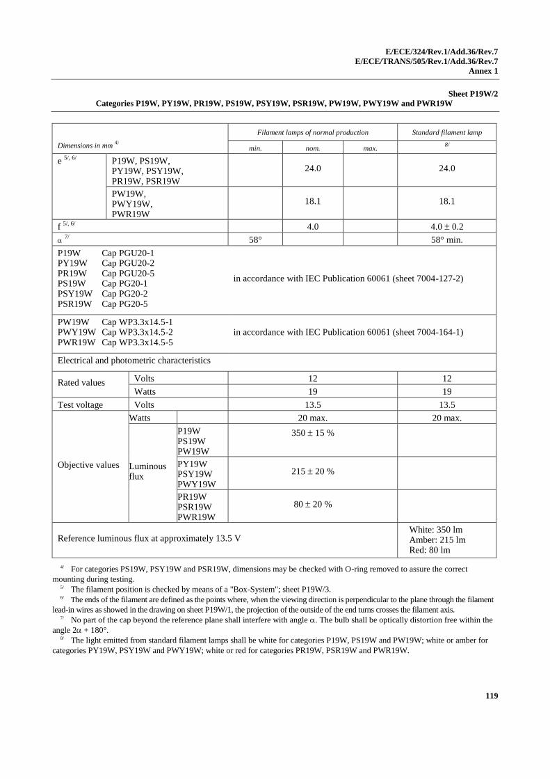
E/ECE/324/Rev.1/Add.36/Rev.7
E/ECE/TRANS/505/Rev.1/Add.36/Rev.7
Annex 1
119
Sheet P19W/2
Categories P19W, PY19W, PR19W, PS19W, PSY19W, PSR19W, PW19W, PWY19W and PWR19W
Dimensions in mm 4/
Filament lamps of normal production Standard filament lamp
min. nom. max. 8/
e 5/, 6/
P19W, PS19W, PY19W, PSY19W, PR19W, PSR19W
24.0 24.0
PW19W, PWY19W, PWR19W
18.1 18.1
f 5/, 6/
4.0 4.0 0.2
7/
58° 58° min.
P19W Cap PGU20-1 PY19W Cap PGU20-2 PR19W Cap PGU20-5 PS19W Cap PG20-1 PSY19W Cap PG20-2 PSR19W Cap PG20-5
in accordance with IEC Publication 60061 (sheet 7004-127-2)
PW19W Cap WP3.3x14.5-1 PWY19W Cap WP3.3x14.5-2 PWR19W Cap WP3.3x14.5-5
in accordance with IEC Publication 60061 (sheet 7004-164-1)
Electrical and photometric characteristics
Rated values Volts 12 12
Watts 19 19
Test voltage Volts 13.5 13.5
Objective values
Watts 20 max. 20 max.
Luminous flux
P19W PS19W PW19W
350 15 %
PY19W PSY19W PWY19W
215 20 %
PR19W PSR19W PWR19W
80 20 %
Reference luminous flux at approximately 13.5 V White: 350 lm Amber: 215 lm Red: 80 lm
4/ For categories PS19W, PSY19W and PSR19W, dimensions may be checked with O-ring removed to assure the correct
mounting during testing. 5/ The filament position is checked by means of a "Box-System"; sheet P19W/3. 6/ The ends of the filament are defined as the points where, when the viewing direction is perpendicular to the plane through the filament
lead-in wires as showed in the drawing on sheet P19W/1, the projection of the outside of the end turns crosses the filament axis. 7/ No part of the cap beyond the reference plane shall interfere with angle . The bulb shall be optically distortion free within the
angle 2 + 180°. 8/ The light emitted from standard filament lamps shall be white for categories P19W, PS19W and PW19W; white or amber for
categories PY19W, PSY19W and PWY19W; white or red for categories PR19W, PSR19W and PWR19W.
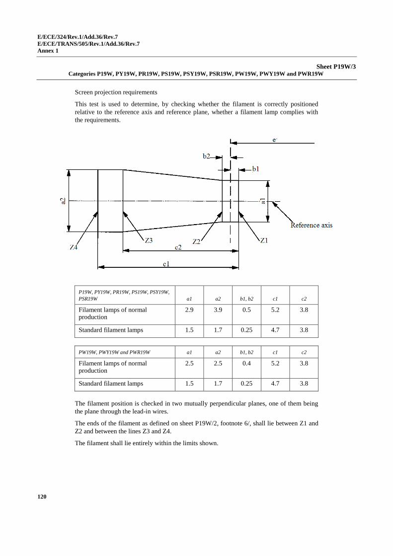
E/ECE/324/Rev.1/Add.36/Rev.7
E/ECE/TRANS/505/Rev.1/Add.36/Rev.7
Annex 1
120
Sheet P19W/3 Categories P19W, PY19W, PR19W, PS19W, PSY19W, PSR19W, PW19W, PWY19W and PWR19W
Screen projection requirements
This test is used to determine, by checking whether the filament is correctly positioned
relative to the reference axis and reference plane, whether a filament lamp complies with
the requirements.
P19W, PY19W, PR19W, PS19W, PSY19W,
PSR19W a1 a2 b1, b2 c1 c2
Filament lamps of normal production
2.9 3.9 0.5 5.2 3.8
Standard filament lamps 1.5 1.7 0.25 4.7 3.8
PW19W, PWY19W and PWR19W a1 a2 b1, b2 c1 c2
Filament lamps of normal production
2.5 2.5 0.4 5.2 3.8
Standard filament lamps 1.5 1.7 0.25 4.7 3.8
The filament position is checked in two mutually perpendicular planes, one of them being
the plane through the lead-in wires.
The ends of the filament as defined on sheet P19W/2, footnote 6/, shall lie between Z1 and
Z2 and between the lines Z3 and Z4.
The filament shall lie entirely within the limits shown.
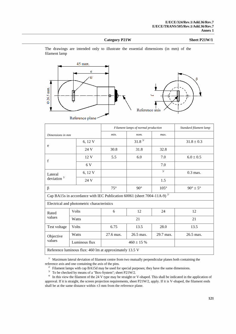
E/ECE/324/Rev.1/Add.36/Rev.7
E/ECE/TRANS/505/Rev.1/Add.36/Rev.7
Annex 1
121
Category P21W Sheet P21W/1
The drawings are intended only to illustrate the essential dimensions (in mm) of the
filament lamp
Dimensions in mm
Filament lamps of normal production Standard filament lamp
min. nom. max.
e 6, 12 V 31.8
3/ 31.8 0.3
24 V 30.8 31.8 32.8
f 12 V 5.5 6.0 7.0 6.0 0.5
6 V 7.0
Lateral deviation
1/
6, 12 V 3/
0.3 max.
24 V 1.5
75° 90° 105° 90° 5°
Cap BA15s in accordance with IEC Publication 60061 (sheet 7004-11A-9) 2/
Electrical and photometric characteristics
Rated values
Volts 6 12 24 12
Watts 21 21
Test voltage Volts 6.75 13.5 28.0 13.5
Objective values
Watts 27.6 max. 26.5 max. 29.7 max. 26.5 max.
Luminous flux 460 15 %
Reference luminous flux: 460 lm at approximately 13.5 V
1/ Maximum lateral deviation of filament centre from two mutually perpendicular planes both containing the
reference axis and one containing the axis of the pins. 2/ Filament lamps with cap BA15d may be used for special purposes; they have the same dimensions. 3/ To be checked by means of a "Box-System"; sheet P21W/2. 4/ In this view the filament of the 24 V type may be straight or V-shaped. This shall be indicated in the application of
approval. If it is straight, the screen projection requirements, sheet P21W/2, apply. If it is V-shaped, the filament ends
shall be at the same distance within ±3 mm from the reference plane.
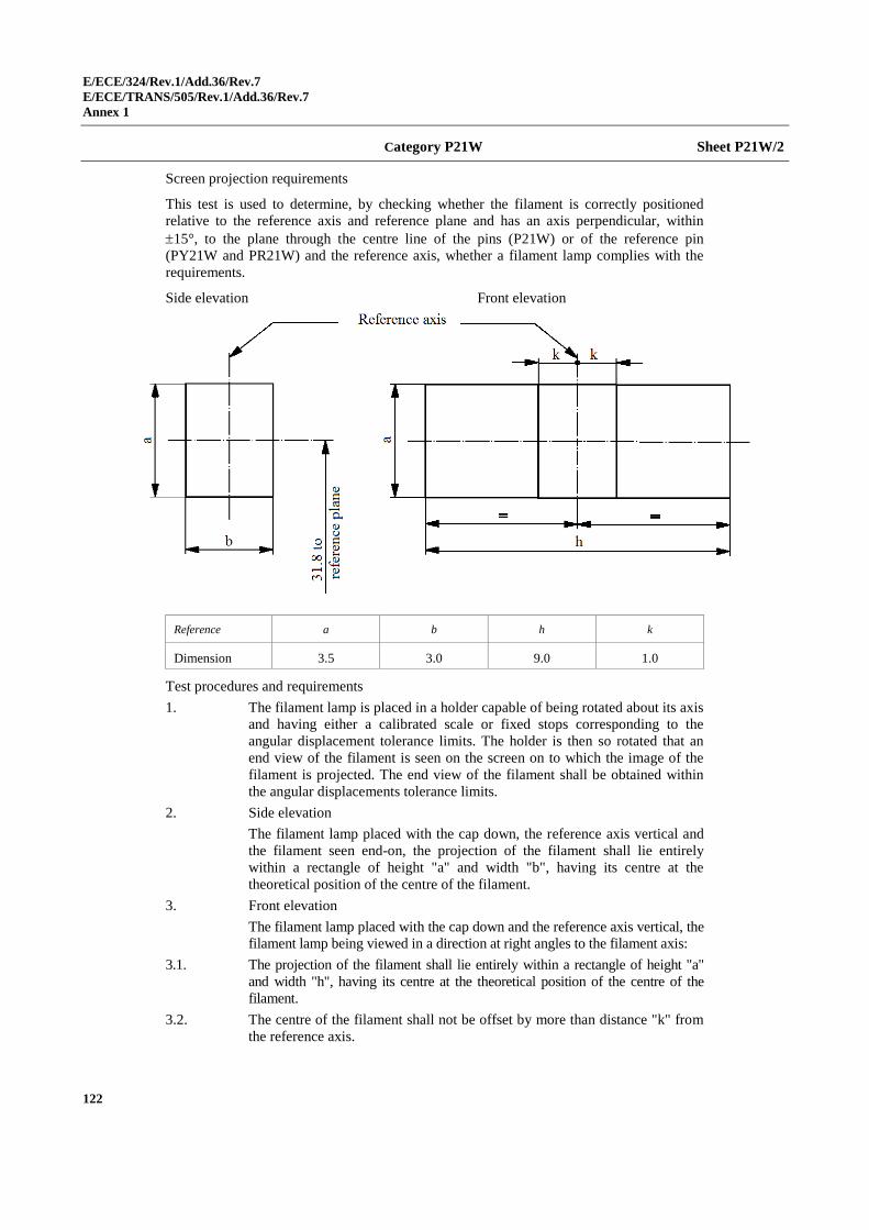
E/ECE/324/Rev.1/Add.36/Rev.7
E/ECE/TRANS/505/Rev.1/Add.36/Rev.7
Annex 1
122
Category P21W Sheet P21W/2
Screen projection requirements
This test is used to determine, by checking whether the filament is correctly positioned
relative to the reference axis and reference plane and has an axis perpendicular, within
15°, to the plane through the centre line of the pins (P21W) or of the reference pin
(PY21W and PR21W) and the reference axis, whether a filament lamp complies with the
requirements.
Side elevation Front elevation
Reference a b h k
Dimension 3.5 3.0 9.0 1.0
Test procedures and requirements
1. The filament lamp is placed in a holder capable of being rotated about its axis
and having either a calibrated scale or fixed stops corresponding to the
angular displacement tolerance limits. The holder is then so rotated that an
end view of the filament is seen on the screen on to which the image of the
filament is projected. The end view of the filament shall be obtained within
the angular displacements tolerance limits.
2. Side elevation
The filament lamp placed with the cap down, the reference axis vertical and
the filament seen end-on, the projection of the filament shall lie entirely
within a rectangle of height "a" and width "b", having its centre at the
theoretical position of the centre of the filament.
3. Front elevation
The filament lamp placed with the cap down and the reference axis vertical, the
filament lamp being viewed in a direction at right angles to the filament axis:
3.1. The projection of the filament shall lie entirely within a rectangle of height "a"
and width "h", having its centre at the theoretical position of the centre of the
filament.
3.2. The centre of the filament shall not be offset by more than distance "k" from
the reference axis.
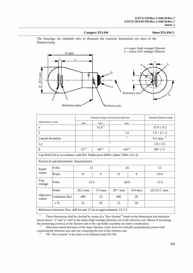
E/ECE/324/Rev.1/Add.36/Rev.7
E/ECE/TRANS/505/Rev.1/Add.36/Rev.7
Annex 1
123
Category P21/4W Sheet P21/4W/1
The drawings are intended only to illustrate the essential dimensions (in mm) of the
filament lamp
Dimensions in mm
Filament lamps of normal production Standard filament lamp
min. nom. max.
e 31.8 1/ 31.8 0.3
f 7.0 7.0 + 0 /- 2
Lateral deviation 1/
0.3 max. 2/
x,y 1/
2.8 0.5
75°1/
90°1/
105°1/ 90° 5°
Cap BAZ15d in accordance with IEC Publication 60061 (sheet 7004-11C-3)
Electrical and photometric characteristics
Rated values
Volts 12 24 12
Watts 21 4 21 4 21/4
Test voltage
Volts 13.5 28.0 13.5
Objective values
Watts 26.5 max. 5.5 max. 29.7 max. 8.8 max. 26.5/5.5 max.
Luminous flux 440 15 440 20
% 15 20 15 20
Reference luminous flux: 440 lm and 15 lm at approximately 13.5 V
1/ These dimensions shall be checked by means of a "Box-System"3 based on the dimensions and tolerances
shown above. "x" and "y" refer to the major (high-wattage) filament, not to the reference axis. Means of increasing
the positioning accuracy of the filament and of the cap-holder assembly are under consideration. 2/ Maximum lateral deviation of the major filament centre from two mutually perpendicular planes both
containing the reference axis and one containing the axis of the reference pin. 3/ The "Box-System" is the same as for filament lamp P21/5W.
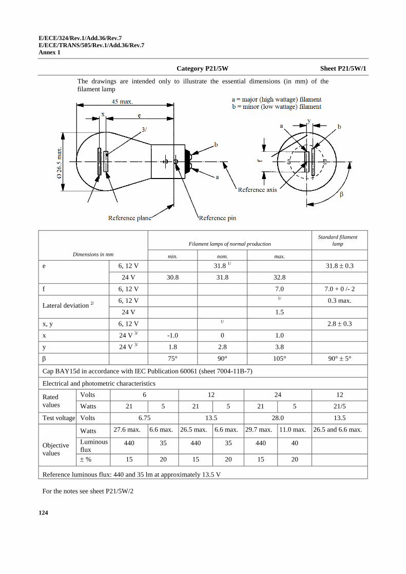
E/ECE/324/Rev.1/Add.36/Rev.7
E/ECE/TRANS/505/Rev.1/Add.36/Rev.7
Annex 1
124
Category P21/5W Sheet P21/5W/1
The drawings are intended only to illustrate the essential dimensions (in mm) of the
filament lamp
Dimensions in mm
Filament lamps of normal production
Standard filament
lamp
min. nom. max.
e 6, 12 V 31.8 1/ 31.8 0.3
24 V 30.8 31.8 32.8
f 6, 12 V 7.0 7.0 + 0 /- 2
Lateral deviation 2/
6, 12 V
1/ 0.3 max.
24 V 1.5
x, y 6, 12 V 1/
2.8 0.3
x 24 V 3/ -1.0 0 1.0
y 24 V 3/ 1.8 2.8 3.8
75° 90° 105° 90° 5°
Cap BAY15d in accordance with IEC Publication 60061 (sheet 7004-11B-7)
Electrical and photometric characteristics
Rated
values
Volts 6 12 24 12
Watts 21 5 21 5 21 5 21/5
Test voltage Volts 6.75 13.5 28.0 13.5
Objective
values
Watts 27.6 max. 6.6 max. 26.5 max. 6.6 max. 29.7 max. 11.0 max. 26.5 and 6.6 max.
Luminous
flux 440 35 440 35 440 40
% 15 20 15 20 15 20
Reference luminous flux: 440 and 35 lm at approximately 13.5 V
For the notes see sheet P21/5W/2
E/ECE/324/Rev.1/Add.36/Rev.7
E/ECE/TRANS/505/Rev.1/Add.36/Rev.7
Annex 1
125
Category P21/5W Sheet P21/5W/2
1/ These dimensions shall be checked by means of a "box-system". See sheets P21/5W/2 and
P21/5W/3. "x" and "y" refer to the major (high-wattage) filament, not to the reference axis. 2/ Maximum lateral deviation of the major (high wattage) filament centre from two mutually
perpendicular planes both containing the reference axis and one containing the axis of the reference pin. 3/ In this view the filaments of the 24 V type may be straight or V-shaped. This shall be indicated in the
application of approval. If the filaments are straight, the screen projection requirements apply. If they are
V-shaped, the ends of each filament shall be at the same distance within ±3 mm from the reference plane.
Screen projection requirements
This test is used to determine, by checking whether:
(a) The major (high wattage) filament is correctly positioned relative to the
reference axis and reference plane and has an axis perpendicular, within ±15°,
to the plane through the centres of the pins and the reference axis; and whether
(b) The minor (low wattage) filament is correctly positioned relative to the major
(high wattage) filament, whether a filament lamp complies with the
requirements.
Test procedure and requirements
1. The filament lamp is placed in a holder capable of being rotated about its axis
and having either a calibrated scale or fixed stops corresponding to the
angular displacement tolerance limits. (i.e. 15°). The holder is then so rotated
that an end view of the major filament is seen on the screen on which the
image of the filament is projected. The end view of that filament shall be
obtained within the angular displacement tolerance limits.
2. Side elevation
The filament lamp placed with the cap down, the reference axis vertical, the
reference pin to the right and the major filament seen end-on:
2.1. The projection of the major filament shall lie entirely within a rectangle of
height "a" and width "b", having its centre at the theoretical position of the
centre of the filament;
2.2. The projection of the minor filament shall lie entirely:
2.2.1. Within a rectangle of width "c" and height "d" having its centre at a distance
"v" to the right of and at a distance "u" above the theoretical position of the
centre of the major filament;
2.2.2. Above a straight line tangential to the upper edge of the projection of the
major filament and rising from left to right at an angle of 25°.
2.2.3. To the right of the projection of the major filament.
3. Front elevation
The filament lamp being placed with the cap down and the reference axis
vertical, the filament lamp being viewed in a direction at right angles to axis
of the major filament:
3.1. The projection of the major filament shall lie entirely within a rectangle of height
"a" and width "h", centred on the theoretical position of the centre of the filament;
3.2. The centre of the major filament shall not be offset by more than distance "k"
from the reference axis.
3.3. The centre of the minor filament axis shall not be offset from the reference
axis by more than 2 mm (0.4 mm for standard filament lamps).
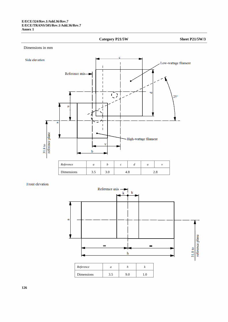
E/ECE/324/Rev.1/Add.36/Rev.7
E/ECE/TRANS/505/Rev.1/Add.36/Rev.7
Annex 1
126
Category P21/5W Sheet P21/5W/3
Dimensions in mm
Reference a b c d u v
Dimensions 3.5 3.0 4.8 2.8
Reference a h k
Dimensions 3.5 9.0 1.0
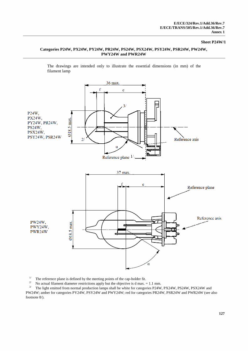
E/ECE/324/Rev.1/Add.36/Rev.7
E/ECE/TRANS/505/Rev.1/Add.36/Rev.7
Annex 1
127
Sheet P24W/1
Categories P24W, PX24W, PY24W, PR24W, PS24W, PSX24W, PSY24W, PSR24W, PW24W,
PWY24W and PWR24W
The drawings are intended only to illustrate the essential dimensions (in mm) of the
filament lamp
1/ The reference plane is defined by the meeting points of the cap-holder fit. 2/ No actual filament diameter restrictions apply but the objective is d max. = 1.1 mm. 3/ The light emitted from normal production lamps shall be white for categories P24W, PX24W, PS24W, PSX24W and
PW24W; amber for categories PY24W, PSY24W and PWY24W; red for categories PR24W, PSR24W and PWR24W (see also
footnote 8/).
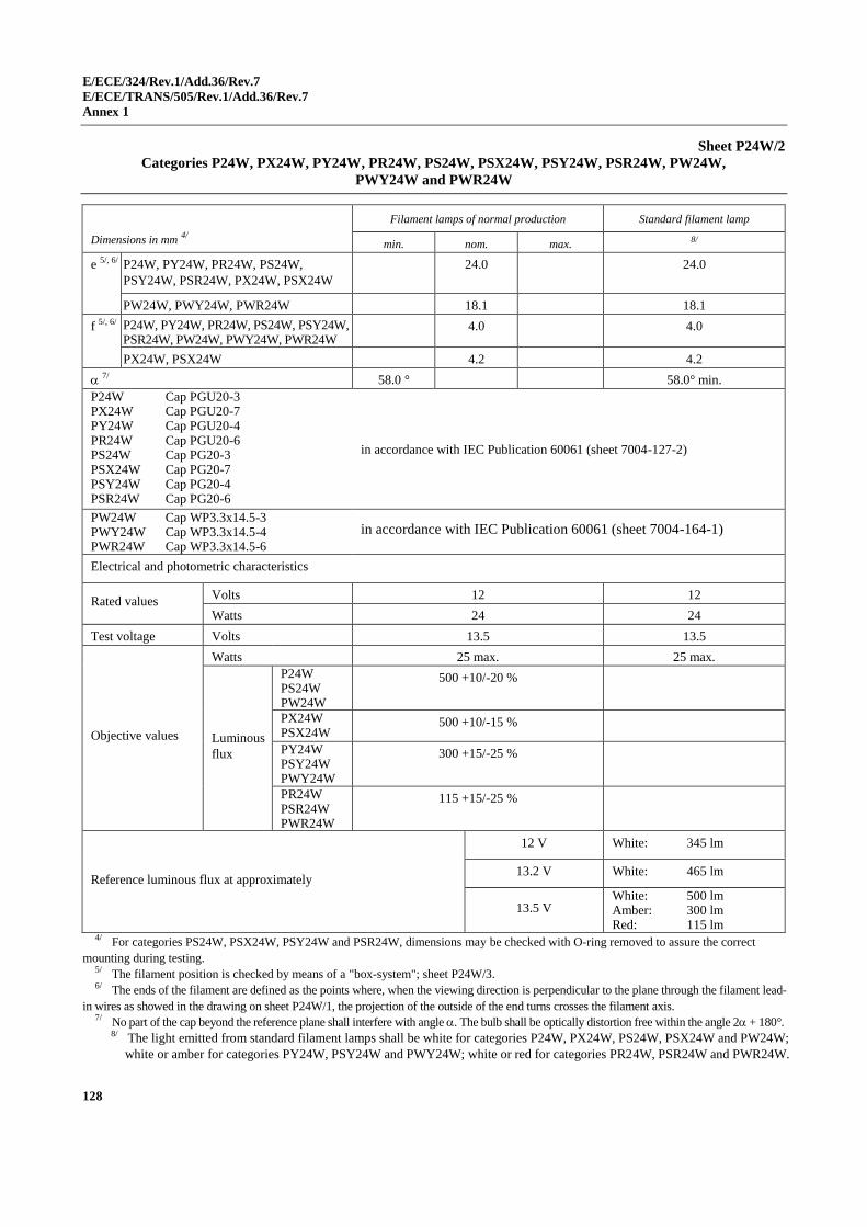
E/ECE/324/Rev.1/Add.36/Rev.7
E/ECE/TRANS/505/Rev.1/Add.36/Rev.7
Annex 1
128
Sheet P24W/2
Categories P24W, PX24W, PY24W, PR24W, PS24W, PSX24W, PSY24W, PSR24W, PW24W,
PWY24W and PWR24W
Dimensions in mm 4/
Filament lamps of normal production Standard filament lamp
min. nom. max. 8/
e 5/, 6/ P24W, PY24W, PR24W, PS24W,
PSY24W, PSR24W, PX24W, PSX24W
24.0 24.0
PW24W, PWY24W, PWR24W 18.1 18.1
f 5/, 6/ P24W, PY24W, PR24W, PS24W, PSY24W, PSR24W, PW24W, PWY24W, PWR24W
4.0 4.0
PX24W, PSX24W 4.2 4.2
7/ 58.0 ° 58.0° min.
P24W Cap PGU20-3 PX24W Cap PGU20-7 PY24W Cap PGU20-4 PR24W Cap PGU20-6 PS24W Cap PG20-3 PSX24W Cap PG20-7 PSY24W Cap PG20-4 PSR24W Cap PG20-6
in accordance with IEC Publication 60061 (sheet 7004-127-2)
PW24W Cap WP3.3x14.5-3 PWY24W Cap WP3.3x14.5-4 PWR24W Cap WP3.3x14.5-6
in accordance with IEC Publication 60061 (sheet 7004-164-1)
Electrical and photometric characteristics
Rated values Volts 12 12
Watts 24 24
Test voltage Volts 13.5 13.5
Objective values
Watts 25 max. 25 max.
Luminous
flux
P24W PS24W PW24W
500 +10/-20 %
PX24W PSX24W
500 +10/-15 %
PY24W PSY24W PWY24W
300 +15/-25 %
PR24W PSR24W PWR24W
115 +15/-25 %
Reference luminous flux at approximately
12 V White: 345 lm
13.2 V White: 465 lm
13.5 V White: 500 lm Amber: 300 lm Red: 115 lm
4/ For categories PS24W, PSX24W, PSY24W and PSR24W, dimensions may be checked with O-ring removed to assure the correct
mounting during testing. 5/ The filament position is checked by means of a "box-system"; sheet P24W/3. 6/ The ends of the filament are defined as the points where, when the viewing direction is perpendicular to the plane through the filament lead-
in wires as showed in the drawing on sheet P24W/1, the projection of the outside of the end turns crosses the filament axis. 7/ No part of the cap beyond the reference plane shall interfere with angle . The bulb shall be optically distortion free within the angle 2 + 180°.
8/ The light emitted from standard filament lamps shall be white for categories P24W, PX24W, PS24W, PSX24W and PW24W;
white or amber for categories PY24W, PSY24W and PWY24W; white or red for categories PR24W, PSR24W and PWR24W.
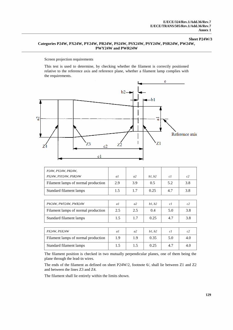
E/ECE/324/Rev.1/Add.36/Rev.7
E/ECE/TRANS/505/Rev.1/Add.36/Rev.7
Annex 1
129
Sheet P24W/3
Categories P24W, PX24W, PY24W, PR24W, PS24W, PSX24W, PSY24W, PSR24W, PW24W,
PWY24W and PWR24W
Screen projection requirements
This test is used to determine, by checking whether the filament is correctly positioned
relative to the reference axis and reference plane, whether a filament lamp complies with
the requirements.
P24W, PY24W, PR24W,
PS24W, PSY24W, PSR24W a1 a2 b1, b2 c1 c2
Filament lamps of normal production 2.9 3.9 0.5 5.2 3.8
Standard filament lamps 1.5 1.7 0.25 4.7 3.8
PW24W, PWY24W, PWR24W a1 a2 b1, b2 c1 c2
Filament lamps of normal production 2.5 2.5 0.4 5.0 3.8
Standard filament lamps 1.5 1.7 0.25 4.7 3.8
PX24W, PSX24W a1 a2 b1, b2 c1 c2
Filament lamps of normal production 1.9 1.9 0.35 5.0 4.0
Standard filament lamps 1.5 1.5 0.25 4.7 4.0
The filament position is checked in two mutually perpendicular planes, one of them being the
plane through the lead-in wires.
The ends of the filament as defined on sheet P24W/2, footnote 6/, shall lie between Z1 and Z2
and between the lines Z3 and Z4.
The filament shall lie entirely within the limits shown.
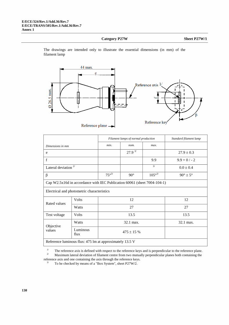
E/ECE/324/Rev.1/Add.36/Rev.7
E/ECE/TRANS/505/Rev.1/Add.36/Rev.7
Annex 1
130
Category P27W Sheet P27W/1
The drawings are intended only to illustrate the essential dimensions (in mm) of the
filament lamp
Dimensions in mm
Filament lamps of normal production Standard filament lamp
min. nom. max.
e 27.9 3/ 27.9 0.3
f 9.9 9.9 + 0 / - 2
Lateral deviation 2/
3/
0.0 0.4
75°3/
90° 105°3/ 90° 5°
Cap W2.5x16d in accordance with IEC Publication 60061 (sheet 7004-104-1)
Electrical and photometric characteristics
Rated values Volts 12 12
Watts 27 27
Test voltage Volts 13.5 13.5
Objective values
Watts 32.1 max. 32.1 max.
Luminous flux
475 15 %
Reference luminous flux: 475 lm at approximately 13.5 V
1/ The reference axis is defined with respect to the reference keys and is perpendicular to the reference plane. 2/ Maximum lateral deviation of filament centre from two mutually perpendicular planes both containing the
reference axis and one containing the axis through the reference keys. 3/ To be checked by means of a "Box System", sheet P27W/2.
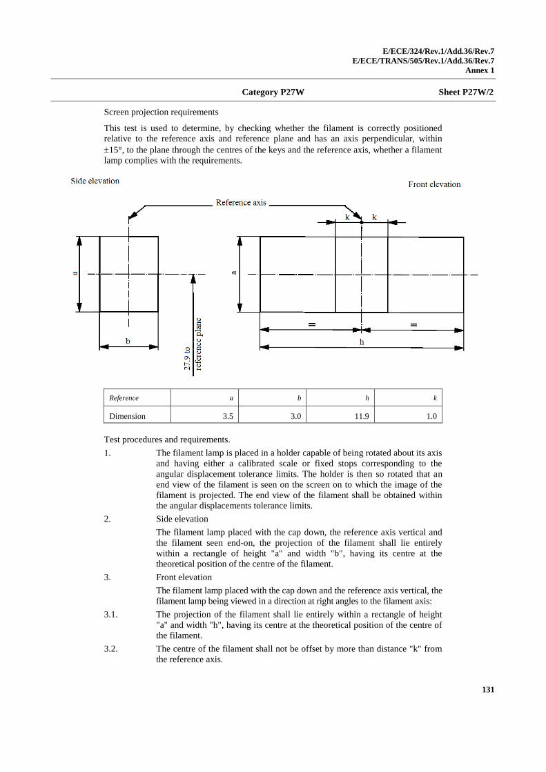
E/ECE/324/Rev.1/Add.36/Rev.7
E/ECE/TRANS/505/Rev.1/Add.36/Rev.7
Annex 1
131
Category P27W Sheet P27W/2
Screen projection requirements
This test is used to determine, by checking whether the filament is correctly positioned
relative to the reference axis and reference plane and has an axis perpendicular, within
15°, to the plane through the centres of the keys and the reference axis, whether a filament
lamp complies with the requirements.
Reference a b h k
Dimension 3.5 3.0 11.9 1.0
Test procedures and requirements.
1. The filament lamp is placed in a holder capable of being rotated about its axis
and having either a calibrated scale or fixed stops corresponding to the
angular displacement tolerance limits. The holder is then so rotated that an
end view of the filament is seen on the screen on to which the image of the
filament is projected. The end view of the filament shall be obtained within
the angular displacements tolerance limits.
2. Side elevation
The filament lamp placed with the cap down, the reference axis vertical and
the filament seen end-on, the projection of the filament shall lie entirely
within a rectangle of height "a" and width "b", having its centre at the
theoretical position of the centre of the filament.
3. Front elevation
The filament lamp placed with the cap down and the reference axis vertical, the
filament lamp being viewed in a direction at right angles to the filament axis:
3.1. The projection of the filament shall lie entirely within a rectangle of height
"a" and width "h", having its centre at the theoretical position of the centre of
the filament.
3.2. The centre of the filament shall not be offset by more than distance "k" from
the reference axis.
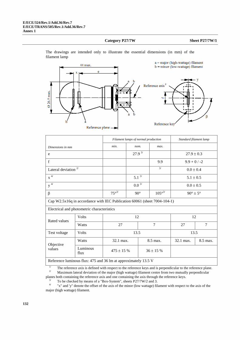
E/ECE/324/Rev.1/Add.36/Rev.7
E/ECE/TRANS/505/Rev.1/Add.36/Rev.7
Annex 1
132
Category P27/7W Sheet P27/7W/1
The drawings are intended only to illustrate the essential dimensions (in mm) of the
filament lamp
Dimensions in mm
Filament lamps of normal production Standard filament lamp
min. nom. max.
e 27.9 3/ 27.9 0.3
f 9.9 9.9 + 0 / -2
Lateral deviation 2/
3/
0.0 0.4
x 4/
5.1 3/ 5.1 0.5
y 4/
0.0 3/ 0.0 0.5
75°3/
90° 105°3/ 90° 5°
Cap W2.5x16q in accordance with IEC Publication 60061 (sheet 7004-104-1)
Electrical and photometric characteristics
Rated values Volts 12 12
Watts 27 7 27 7
Test voltage Volts 13.5 13.5
Objective values
Watts 32.1 max. 8.5 max. 32.1 max. 8.5 max.
Luminous flux
475 15 % 36 15 %
Reference luminous flux: 475 and 36 lm at approximately 13.5 V
1/ The reference axis is defined with respect to the reference keys and is perpendicular to the reference plane. 2/ Maximum lateral deviation of the major (high wattage) filament centre from two mutually perpendicular
planes both containing the reference axis and one containing the axis through the reference keys. 3/ To be checked by means of a "Box-System", sheets P27/7W/2 and 3. 4/ "x" and 'y" denote the offset of the axis of the minor (low wattage) filament with respect to the axis of the
major (high wattage) filament.
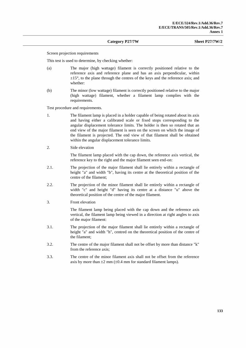
E/ECE/324/Rev.1/Add.36/Rev.7
E/ECE/TRANS/505/Rev.1/Add.36/Rev.7
Annex 1
133
Category P27/7W Sheet P27/7W/2
Screen projection requirements
This test is used to determine, by checking whether:
(a) The major (high wattage) filament is correctly positioned relative to the
reference axis and reference plane and has an axis perpendicular, within
±15°, to the plane through the centres of the keys and the reference axis; and
whether:
(b) The minor (low wattage) filament is correctly positioned relative to the major
(high wattage) filament, whether a filament lamp complies with the
requirements.
Test procedure and requirements.
1. The filament lamp is placed in a holder capable of being rotated about its axis
and having either a calibrated scale or fixed stops corresponding to the
angular displacement tolerance limits. The holder is then so rotated that an
end view of the major filament is seen on the screen on which the image of
the filament is projected. The end view of that filament shall be obtained
within the angular displacement tolerance limits.
2. Side elevation
The filament lamp placed with the cap down, the reference axis vertical, the
reference key to the right and the major filament seen end-on:
2.1. The projection of the major filament shall lie entirely within a rectangle of
height "a" and width "b", having its centre at the theoretical position of the
centre of the filament;
2.2. The projection of the minor filament shall lie entirely within a rectangle of
width "c" and height "d" having its centre at a distance "u" above the
theoretical position of the centre of the major filament.
3. Front elevation
The filament lamp being placed with the cap down and the reference axis
vertical, the filament lamp being viewed in a direction at right angles to axis
of the major filament:
3.1. The projection of the major filament shall lie entirely within a rectangle of
height "a" and width "h", centred on the theoretical position of the centre of
the filament;
3.2. The centre of the major filament shall not be offset by more than distance "k"
from the reference axis;
3.3. The centre of the minor filament axis shall not be offset from the reference
axis by more than 2 mm (0.4 mm for standard filament lamps).
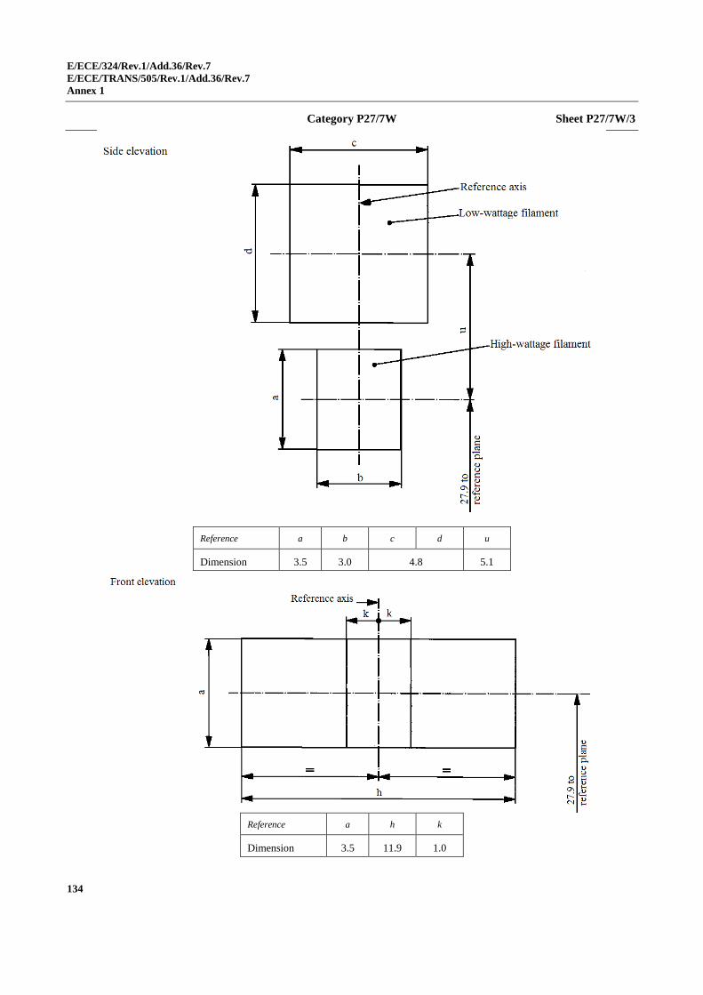
E/ECE/324/Rev.1/Add.36/Rev.7
E/ECE/TRANS/505/Rev.1/Add.36/Rev.7
Annex 1
134
Category P27/7W Sheet P27/7W/3
Reference a b c d u
Dimension 3.5 3.0 4.8 5.1
Reference a h k
Dimension 3.5 11.9 1.0
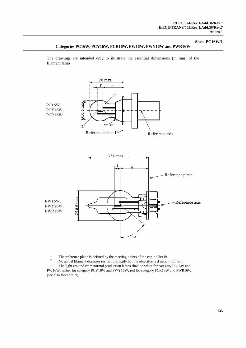
E/ECE/324/Rev.1/Add.36/Rev.7
E/ECE/TRANS/505/Rev.1/Add.36/Rev.7
Annex 1
135
Sheet PC16W/1
Categories PC16W, PCY16W, PCR16W, PW16W, PWY16W and PWR16W
The drawings are intended only to illustrate the essential dimensions (in mm) of the
filament lamp
1/ The reference plane is defined by the meeting points of the cap-holder fit. 2/ No actual filament diameter restrictions apply but the objective is d max. = 1.1 mm. 3/ The light emitted from normal production lamps shall be white for category PC16W and
PW16W; amber for category PCY16W and PWY16W; red for category PCR16W and PWR16W.
(see also footnote 7/).
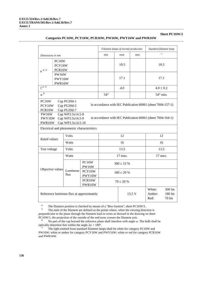
E/ECE/324/Rev.1/Add.36/Rev.7
E/ECE/TRANS/505/Rev.1/Add.36/Rev.7
Annex 1
136
Sheet PC16W/2
Categories PC16W, PCY16W, PCR16W, PW16W, PWY16W and PWR16W
Dimensions in mm
Filament lamps of normal production Standard filament lamp
min. nom. max. 7/
e 4/, 5/
PC16W
PCY16W
PCR16W
18.5 18.5
PW16W
PWY16W
PWR16W
17.1 17.1
f 4/, 5/
4.0 4.0 0.2
α 6/
54° 54° min.
PC16W Cap PU20d-1
PCY16W Cap PU20d-2
PCR16W Cap PU20d-7
in accordance with IEC Publication 60061 (sheet 7004-157-1)
PW16W Cap WP3.3x14.5-8
PWY16W Cap WP3.3x14.5-9
PWR16W Cap WP3.3x14.5-10
in accordance with IEC Publication 60061 (sheet 7004-164-1)
Electrical and photometric characteristics
Rated values Volts 12 12
Watts 16 16
Test voltage Volts 13.5 13.5
Objective values
Watts 17 max. 17 max.
Luminous flux
PC16W
PW16W 300 15 %
PCY16W
PWY16W 180 20 %
PCR16W
PWR16W 70 20 %
Reference luminous flux at approximately 13.5 V
White: 300 lm
Amber: 180 lm
Red: 70 lm
4/ The filament position is checked by means of a "Box-System"; sheet PC16W/3. 5/ The ends of the filament are defined as the points where, when the viewing direction is
perpendicular to the plane through the filament lead-in wires as showed in the drawing on sheet
PC16W/1, the projection of the outside of the end turns crosses the filament axis. 6/ No part of the cap beyond the reference plane shall interfere with angle . The bulb shall be
optically distortion free within the angle 2 + 180°. 7/ The light emitted from standard filament lamps shall be white for category PC16W and
PW16W; white or amber for category PCY16W and PWY16W; white or red for category PCR16W
and PWR16W.
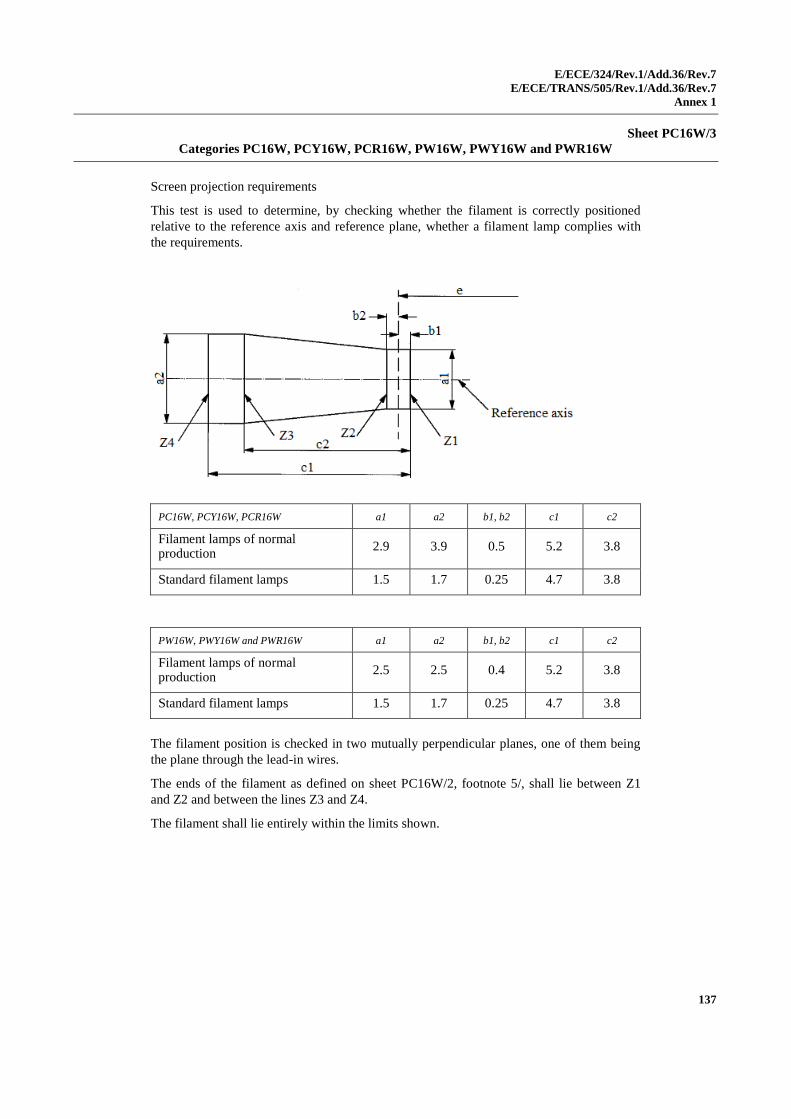
E/ECE/324/Rev.1/Add.36/Rev.7
E/ECE/TRANS/505/Rev.1/Add.36/Rev.7
Annex 1
137
Sheet PC16W/3
Categories PC16W, PCY16W, PCR16W, PW16W, PWY16W and PWR16W
Screen projection requirements
This test is used to determine, by checking whether the filament is correctly positioned
relative to the reference axis and reference plane, whether a filament lamp complies with
the requirements.
PC16W, PCY16W, PCR16W a1 a2 b1, b2 c1 c2
Filament lamps of normal production
2.9 3.9 0.5 5.2 3.8
Standard filament lamps 1.5 1.7 0.25 4.7 3.8
PW16W, PWY16W and PWR16W a1 a2 b1, b2 c1 c2
Filament lamps of normal production
2.5 2.5 0.4 5.2 3.8
Standard filament lamps 1.5 1.7 0.25 4.7 3.8
The filament position is checked in two mutually perpendicular planes, one of them being
the plane through the lead-in wires.
The ends of the filament as defined on sheet PC16W/2, footnote 5/, shall lie between Z1
and Z2 and between the lines Z3 and Z4.
The filament shall lie entirely within the limits shown.
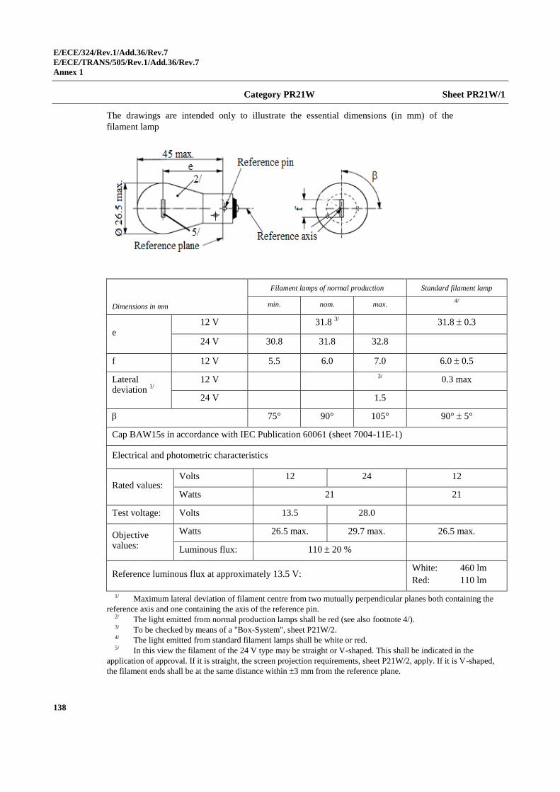
E/ECE/324/Rev.1/Add.36/Rev.7
E/ECE/TRANS/505/Rev.1/Add.36/Rev.7
Annex 1
138
Category PR21W Sheet PR21W/1
The drawings are intended only to illustrate the essential dimensions (in mm) of the
filament lamp
Dimensions in mm
Filament lamps of normal production Standard filament lamp
min. nom. max. 4/
e 12 V 31.8
3/ 31.8 0.3
24 V 30.8 31.8 32.8
f 12 V 5.5 6.0 7.0 6.0 0.5
Lateral deviation
1/
12 V 3/
0.3 max
24 V 1.5
75° 90° 105° 90° 5°
Cap BAW15s in accordance with IEC Publication 60061 (sheet 7004-11E-1)
Electrical and photometric characteristics
Rated values: Volts 12 24 12
Watts 21 21
Test voltage: Volts 13.5 28.0
Objective values:
Watts 26.5 max. 29.7 max. 26.5 max.
Luminous flux: 110 20 %
Reference luminous flux at approximately 13.5 V: White: 460 lm
Red: 110 lm
1/ Maximum lateral deviation of filament centre from two mutually perpendicular planes both containing the
reference axis and one containing the axis of the reference pin. 2/ The light emitted from normal production lamps shall be red (see also footnote 4/). 3/ To be checked by means of a "Box-System", sheet P21W/2. 4/ The light emitted from standard filament lamps shall be white or red. 5/ In this view the filament of the 24 V type may be straight or V-shaped. This shall be indicated in the
application of approval. If it is straight, the screen projection requirements, sheet P21W/2, apply. If it is V-shaped,
the filament ends shall be at the same distance within 3 mm from the reference plane.
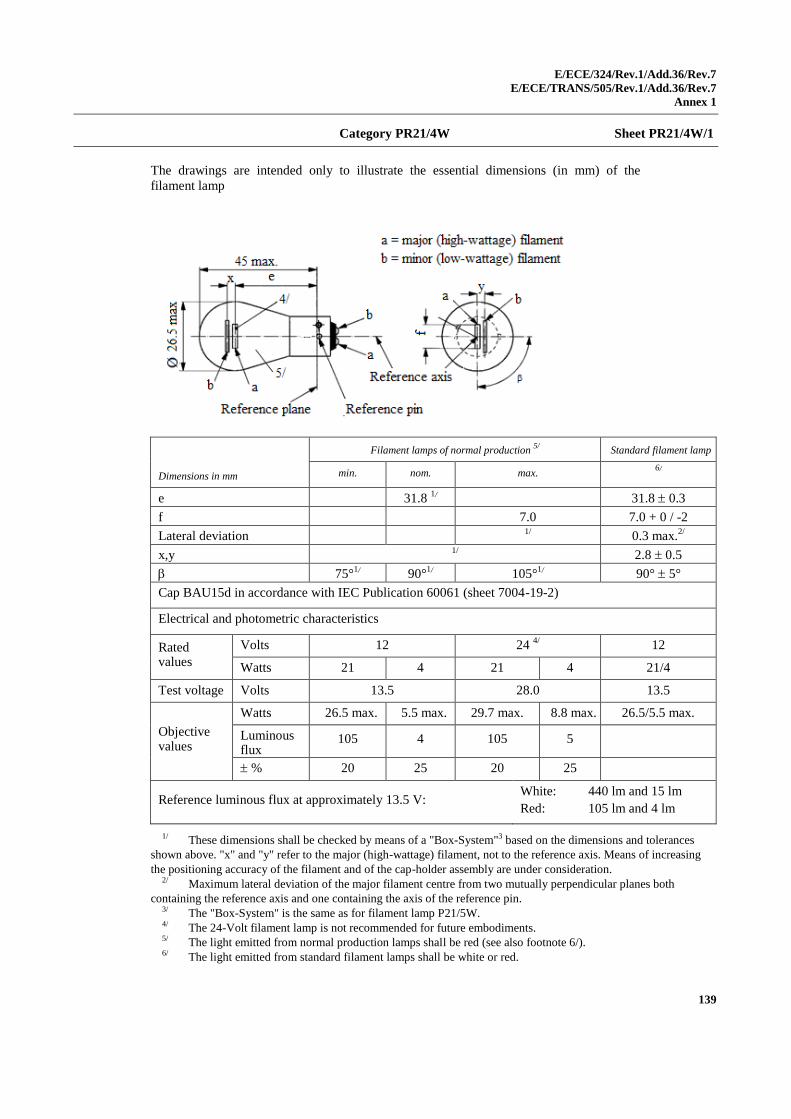
E/ECE/324/Rev.1/Add.36/Rev.7
E/ECE/TRANS/505/Rev.1/Add.36/Rev.7
Annex 1
139
Category PR21/4W Sheet PR21/4W/1
The drawings are intended only to illustrate the essential dimensions (in mm) of the
filament lamp
Dimensions in mm
Filament lamps of normal production 5/
Standard filament lamp
min. nom. max. 6/
e 31.8 1/ 31.8 0.3
f 7.0 7.0 + 0 / -2
Lateral deviation 1/
0.3 max.2/
x,y 1/
2.8 0.5
75°1/ 90°
1/ 105°1/ 90° 5°
Cap BAU15d in accordance with IEC Publication 60061 (sheet 7004-19-2)
Electrical and photometric characteristics
Rated values
Volts 12 24 4/ 12
Watts 21 4 21 4 21/4
Test voltage Volts 13.5 28.0 13.5
Objective values
Watts 26.5 max. 5.5 max. 29.7 max. 8.8 max. 26.5/5.5 max.
Luminous flux
105 4 105 5
% 20 25 20 25
Reference luminous flux at approximately 13.5 V: White: 440 lm and 15 lm
Red: 105 lm and 4 lm
1/ These dimensions shall be checked by means of a "Box-System"3 based on the dimensions and tolerances
shown above. "x" and "y" refer to the major (high-wattage) filament, not to the reference axis. Means of increasing
the positioning accuracy of the filament and of the cap-holder assembly are under consideration. 2/ Maximum lateral deviation of the major filament centre from two mutually perpendicular planes both
containing the reference axis and one containing the axis of the reference pin. 3/ The "Box-System" is the same as for filament lamp P21/5W. 4/ The 24-Volt filament lamp is not recommended for future embodiments. 5/ The light emitted from normal production lamps shall be red (see also footnote 6/). 6/ The light emitted from standard filament lamps shall be white or red.
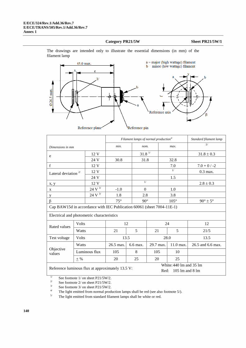
E/ECE/324/Rev.1/Add.36/Rev.7
E/ECE/TRANS/505/Rev.1/Add.36/Rev.7
Annex 1
140
Category PR21/5W Sheet PR21/5W/1
The drawings are intended only to illustrate the essential dimensions (in mm) of the
filament lamp
Dimensions in mm
Filament lamps of normal production4/ Standard filament lamp
min. nom. max. 5/
e 12 V 31.8 1/ 31.8 0.3
24 V 30.8 31.8 32.8
f 12 V 7.0 7.0 + 0 / -2
Lateral deviation 2/
12 V 1/
0.3 max.
24 V 1.5
x, y 12 V 1/
2.8 0.3
x 24 V 3/ -1.0 0 1.0
y 24 V 3/ 1.8 2.8 3.8
75° 90° 105° 90° 5°
Cap BAW15d in accordance with IEC Publication 60061 (sheet 7004-11E-1)
Electrical and photometric characteristics
Rated values Volts 12 24 12
Watts 21 5 21 5 21/5
Test voltage Volts 13.5 28.0 13.5
Objective values
Watts 26.5 max. 6.6 max. 29.7 max. 11.0 max. 26.5 and 6.6 max.
Luminous flux
%
105 8 105 10
+ % 20 25 20 25
Reference luminous flux at approximately 13.5 V: White: 440 lm and 35 lm
Red: 105 lm and 8 lm
1/ See footnote 1/ on sheet P21/5W/2. 2/ See footnote 2/ on sheet P21/5W/2. 3/ See footnote 3/ on sheet P21/5W/2. 4/ The light emitted from normal production lamps shall be red (see also footnote 5/). 5/ The light emitted from standard filament lamps shall be white or red.
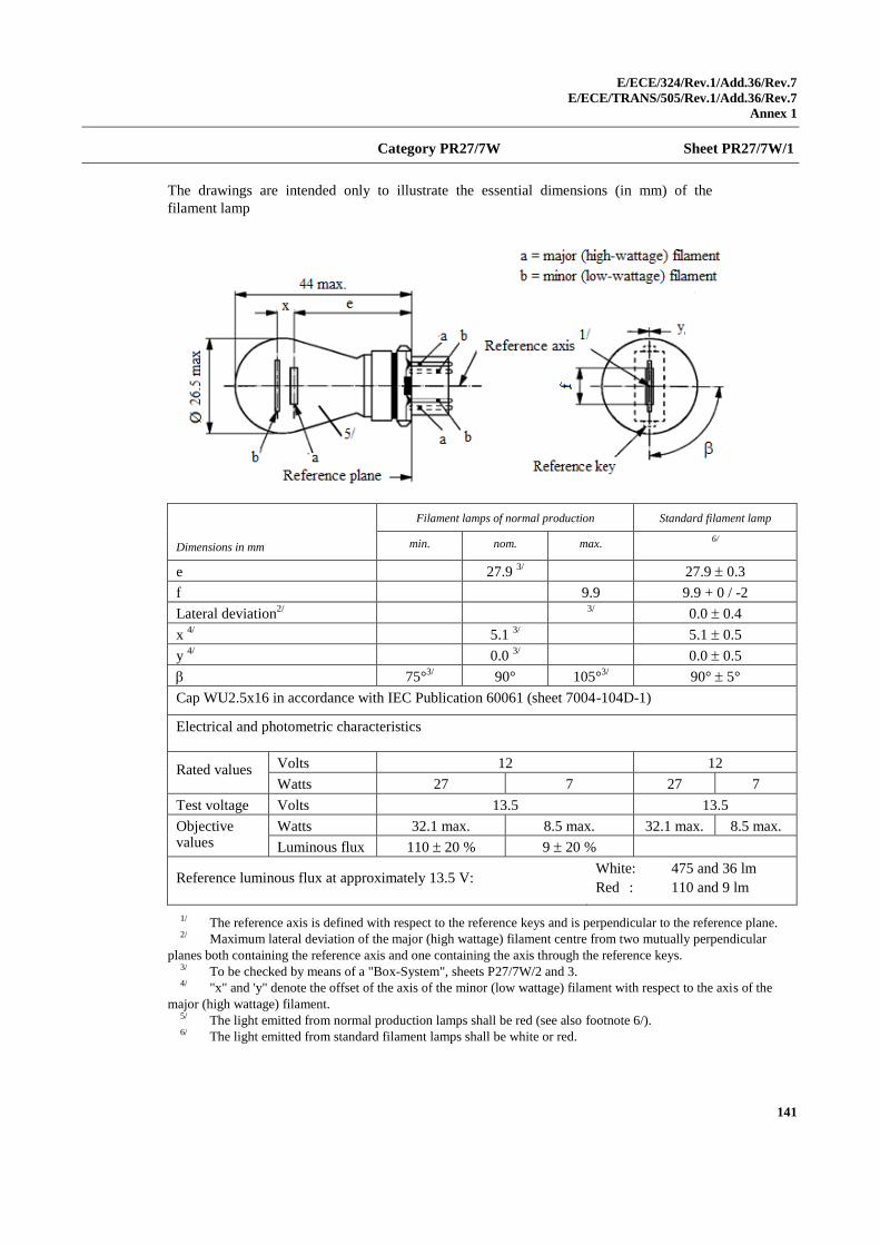
E/ECE/324/Rev.1/Add.36/Rev.7
E/ECE/TRANS/505/Rev.1/Add.36/Rev.7
Annex 1
141
Category PR27/7W Sheet PR27/7W/1
The drawings are intended only to illustrate the essential dimensions (in mm) of the
filament lamp
Dimensions in mm
Filament lamps of normal production Standard filament lamp
min. nom. max. 6/
e 27.9 3/ 27.9 0.3
f 9.9 9.9 + 0 / -2
Lateral deviation2/
3/
0.0 0.4
x 4/
5.1 3/ 5.1 0.5
y 4/
0.0 3/ 0.0 0.5
75°3/
90° 105°3/ 90° 5°
Cap WU2.5x16 in accordance with IEC Publication 60061 (sheet 7004-104D-1)
Electrical and photometric characteristics
Rated values Volts 12 12
Watts 27 7 27 7
Test voltage Volts 13.5 13.5
Objective values
Watts 32.1 max. 8.5 max. 32.1 max. 8.5 max.
Luminous flux 110 20 % 9 20 %
Reference luminous flux at approximately 13.5 V: White: 475 and 36 lm
Red : 110 and 9 lm
1/ The reference axis is defined with respect to the reference keys and is perpendicular to the reference plane. 2/ Maximum lateral deviation of the major (high wattage) filament centre from two mutually perpendicular
planes both containing the reference axis and one containing the axis through the reference keys. 3/ To be checked by means of a "Box-System", sheets P27/7W/2 and 3. 4/ "x" and 'y" denote the offset of the axis of the minor (low wattage) filament with respect to the axis of the
major (high wattage) filament. 5/ The light emitted from normal production lamps shall be red (see also footnote 6/). 6/ The light emitted from standard filament lamps shall be white or red.
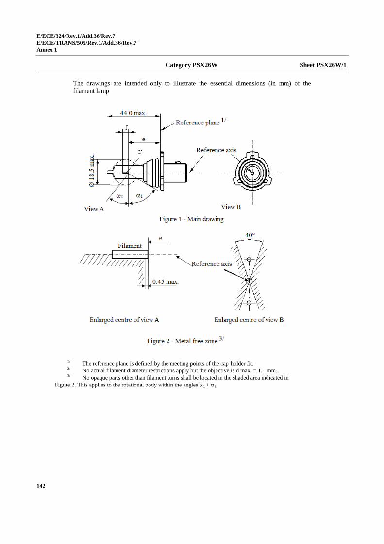
E/ECE/324/Rev.1/Add.36/Rev.7
E/ECE/TRANS/505/Rev.1/Add.36/Rev.7
Annex 1
142
Category PSX26W Sheet PSX26W/1
The drawings are intended only to illustrate the essential dimensions (in mm) of the
filament lamp
1/ The reference plane is defined by the meeting points of the cap-holder fit. 2/ No actual filament diameter restrictions apply but the objective is d max. = 1.1 mm. 3/ No opaque parts other than filament turns shall be located in the shaded area indicated in
Figure 2. This applies to the rotational body within the angles 1 + 2.
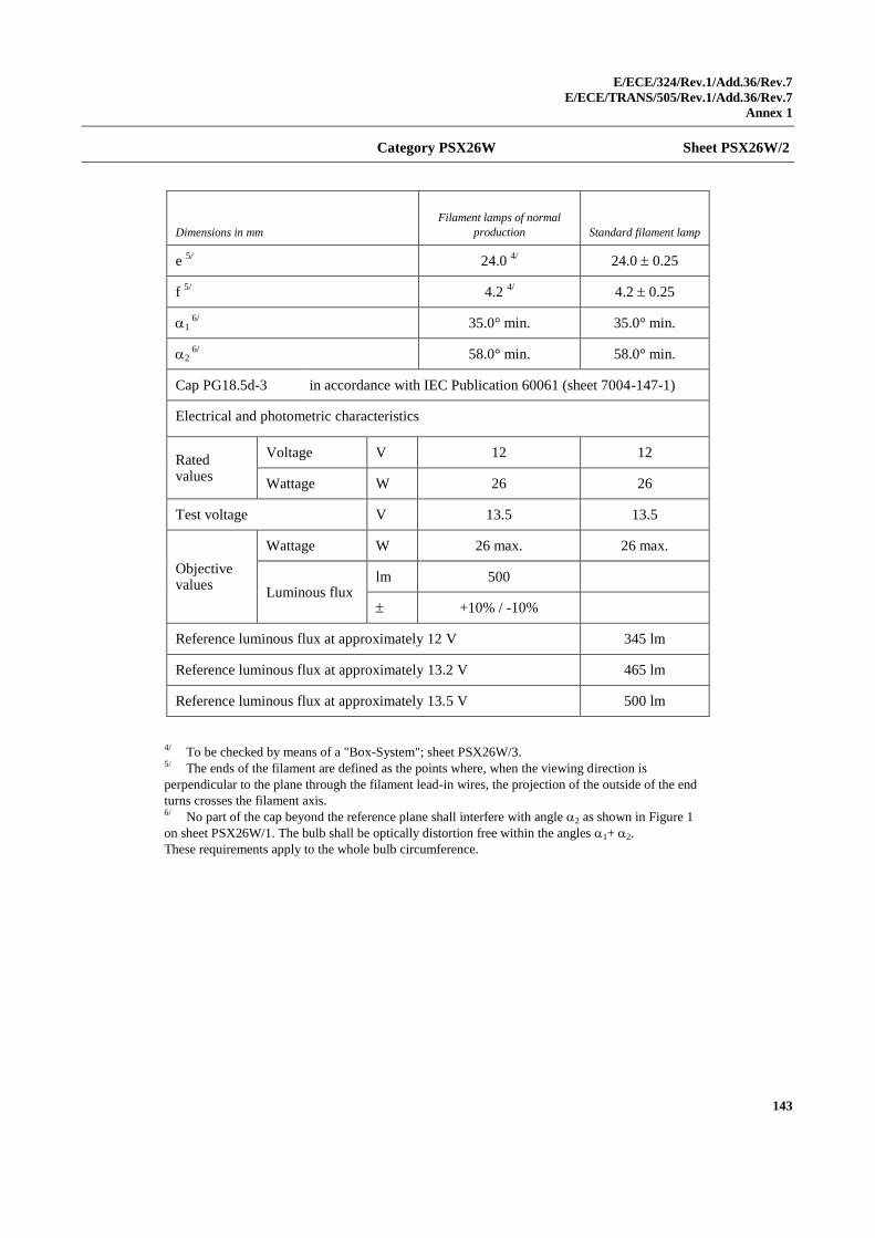
E/ECE/324/Rev.1/Add.36/Rev.7
E/ECE/TRANS/505/Rev.1/Add.36/Rev.7
Annex 1
143
Category PSX26W Sheet PSX26W/2
4/ To be checked by means of a "Box-System"; sheet PSX26W/3.
5/ The ends of the filament are defined as the points where, when the viewing direction is
perpendicular to the plane through the filament lead-in wires, the projection of the outside of the end
turns crosses the filament axis. 6/ No part of the cap beyond the reference plane shall interfere with angle 2 as shown in Figure 1
on sheet PSX26W/1. The bulb shall be optically distortion free within the angles 1+ 2.
These requirements apply to the whole bulb circumference.
Dimensions in mm
Filament lamps of normal
production Standard filament lamp
e 5/
24.0 4/ 24.0 0.25
f 5/
4.2 4/ 4.2 0.25
1 6/
35.0° min. 35.0° min.
2 6/
58.0° min. 58.0° min.
Cap PG18.5d-3 in accordance with IEC Publication 60061 (sheet 7004-147-1)
Electrical and photometric characteristics
Rated values
Voltage V 12 12
Wattage W 26 26
Test voltage V 13.5 13.5
Objective values
Wattage W 26 max. 26 max.
Luminous flux lm 500
+10% / -10%
Reference luminous flux at approximately 12 V 345 lm
Reference luminous flux at approximately 13.2 V 465 lm
Reference luminous flux at approximately 13.5 V 500 lm
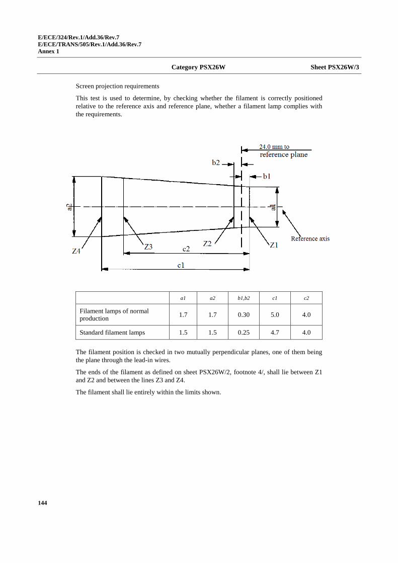
E/ECE/324/Rev.1/Add.36/Rev.7
E/ECE/TRANS/505/Rev.1/Add.36/Rev.7
Annex 1
144
Category PSX26W Sheet PSX26W/3
Screen projection requirements
This test is used to determine, by checking whether the filament is correctly positioned
relative to the reference axis and reference plane, whether a filament lamp complies with
the requirements.
a1 a2 b1,b2 c1 c2
Filament lamps of normal production
1.7 1.7 0.30 5.0 4.0
Standard filament lamps 1.5 1.5 0.25 4.7 4.0
The filament position is checked in two mutually perpendicular planes, one of them being
the plane through the lead-in wires.
The ends of the filament as defined on sheet PSX26W/2, footnote 4/, shall lie between Z1
and Z2 and between the lines Z3 and Z4.
The filament shall lie entirely within the limits shown.
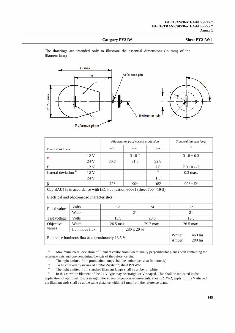
E/ECE/324/Rev.1/Add.36/Rev.7
E/ECE/TRANS/505/Rev.1/Add.36/Rev.7
Annex 1
145
Category PY21W Sheet PY21W/1
The drawings are intended only to illustrate the essential dimensions (in mm) of the
filament lamp
Dimensions in mm
Filament lamps of normal production Standard filament lamp
min. nom. max. 4/
e 12 V 31.8 3/ 31.8 0.3
24 V 30.8 31.8 32.8
f 12 V 7.0 7.0 +0 / -2
Lateral deviation 1/
12 V 3/
0.3 max.
24 V 1.5
75° 90° 105° 90° 5°
Cap BAU15s in accordance with IEC Publication 60061 (sheet 7004-19-2)
Electrical and photometric characteristics
Rated values Volts 12 24 12
Watts 21 21
Test voltage Volts 13.5 28.0 13.5
Objective values
Watts 26.5 max. 29.7 max. 26.5 max.
Luminous flux 280 20 %
Reference luminous flux at approximately 13.5 V: White: 460 lm
Amber: 280 lm
1/ Maximum lateral deviation of filament centre from two mutually perpendicular planes both containing the
reference axis and one containing the axis of the reference pin. 2/ The light emitted from production lamps shall be amber (see also footnote 4/). 3/ To be checked by means of a "Box-System"; sheet P21W/2. 4/ The light emitted from standard filament lamps shall be amber or white. 5/ In this view the filament of the 24 V type may be straight or V-shaped. This shall be indicated in the
application of approval. If it is straight, the screen projection requirements, sheet P21W/2, apply. If it is V-shaped,
the filament ends shall be at the same distance within ±3 mm from the reference plane.
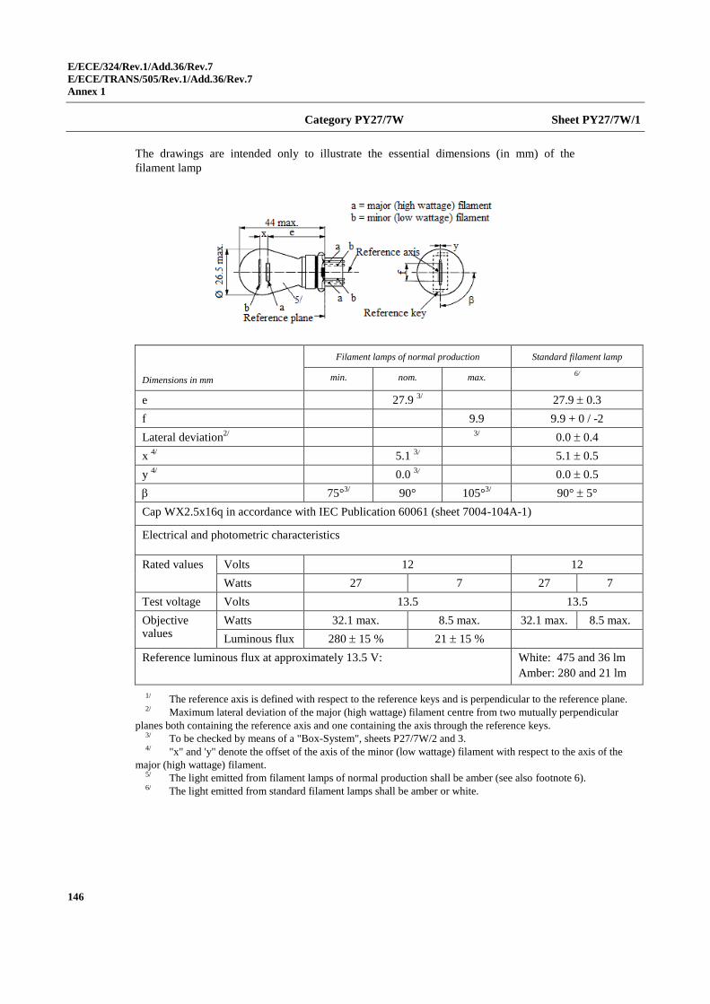
E/ECE/324/Rev.1/Add.36/Rev.7
E/ECE/TRANS/505/Rev.1/Add.36/Rev.7
Annex 1
146
Category PY27/7W Sheet PY27/7W/1
The drawings are intended only to illustrate the essential dimensions (in mm) of the
filament lamp
Dimensions in mm
Filament lamps of normal production Standard filament lamp
min. nom. max. 6/
e 27.9 3/ 27.9 0.3
f 9.9 9.9 + 0 / -2
Lateral deviation2/
3/
0.0 0.4
x 4/
5.1 3/ 5.1 0.5
y 4/
0.0 3/ 0.0 0.5
75°3/
90° 105°3/ 90° 5°
Cap WX2.5x16q in accordance with IEC Publication 60061 (sheet 7004-104A-1)
Electrical and photometric characteristics
Rated values Volts 12 12
Watts 27 7 27 7
Test voltage Volts 13.5 13.5
Objective values
Watts 32.1 max. 8.5 max. 32.1 max. 8.5 max.
Luminous flux 280 15 % 21 15 %
Reference luminous flux at approximately 13.5 V:
White: 475 and 36 lm
Amber: 280 and 21 lm
1/ The reference axis is defined with respect to the reference keys and is perpendicular to the reference plane. 2/ Maximum lateral deviation of the major (high wattage) filament centre from two mutually perpendicular
planes both containing the reference axis and one containing the axis through the reference keys. 3/ To be checked by means of a "Box-System", sheets P27/7W/2 and 3. 4/ "x" and 'y" denote the offset of the axis of the minor (low wattage) filament with respect to the axis of the
major (high wattage) filament. 5/ The light emitted from filament lamps of normal production shall be amber (see also footnote 6). 6/ The light emitted from standard filament lamps shall be amber or white.
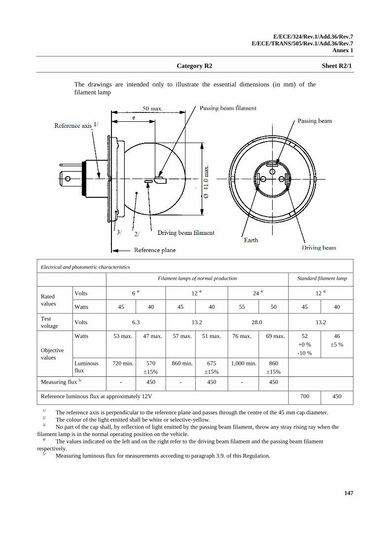
E/ECE/324/Rev.1/Add.36/Rev.7
E/ECE/TRANS/505/Rev.1/Add.36/Rev.7
Annex 1
147
Category R2 Sheet R2/1
The drawings are intended only to illustrate the essential dimensions (in mm) of the
filament lamp
Electrical and photometric characteristics
Filament lamps of normal production Standard filament lamp
Rated
values
Volts 6 4/ 12 4/ 24 4/ 12 4/
Watts 45 40 45 40 55 50 45 40
Test
voltage Volts 6.3 13.2 28.0 13.2
Objective
values
Watts 53 max. 47 max. 57 max. 51 max. 76 max. 69 max. 52
+0 %
-10 %
46
5 %
Luminous
flux
720 min. 570
15%
860 min. 675
15%
1,000 min. 860
15%
Measuring flux 5/ - 450 - 450 - 450
Reference luminous flux at approximately 12V 700 450
1/ The reference axis is perpendicular to the reference plane and passes through the centre of the 45 mm cap diameter. 2/ The colour of the light emitted shall be white or selective-yellow. 3/ No part of the cap shall, by reflection of light emitted by the passing beam filament, throw any stray rising ray when the
filament lamp is in the normal operating position on the vehicle. 4/ The values indicated on the left and on the right refer to the driving beam filament and the passing beam filament
respectively. 5/ Measuring luminous flux for measurements according to paragraph 3.9. of this Regulation.
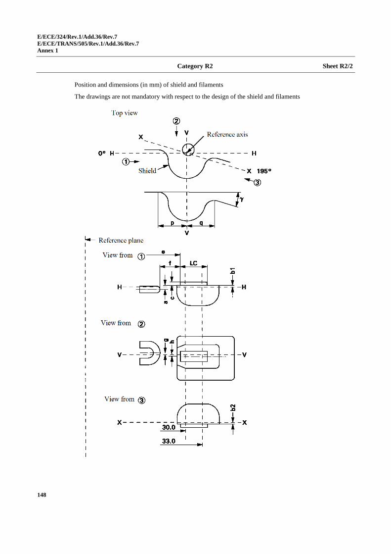
E/ECE/324/Rev.1/Add.36/Rev.7
E/ECE/TRANS/505/Rev.1/Add.36/Rev.7
Annex 1
148
Category R2 Sheet R2/2
Position and dimensions (in mm) of shield and filaments
The drawings are not mandatory with respect to the design of the shield and filaments
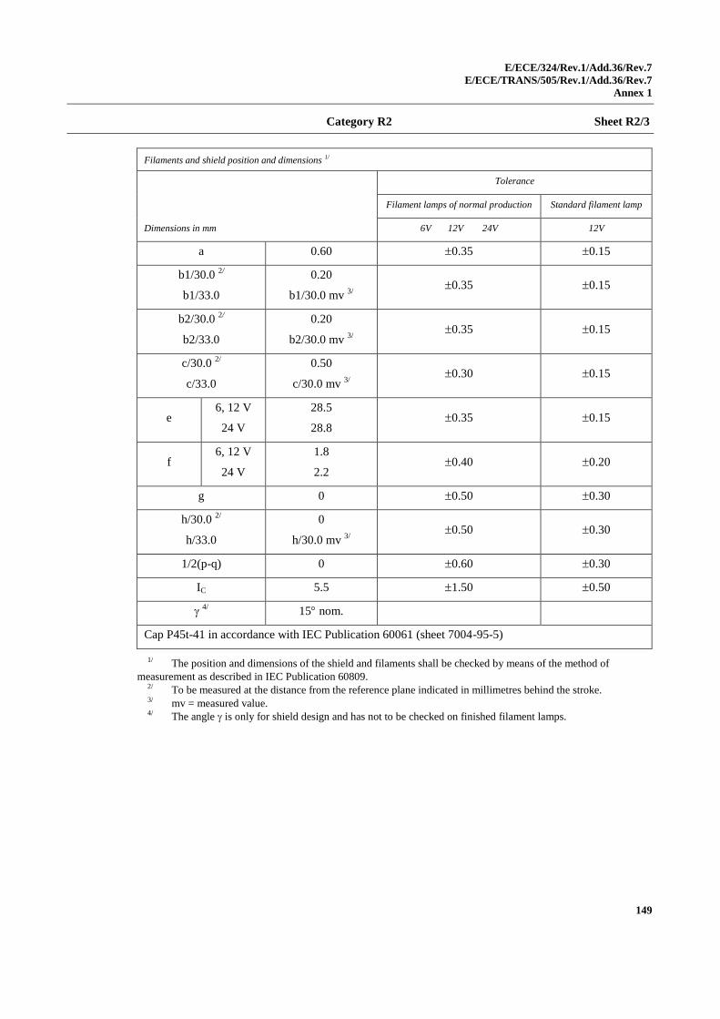
E/ECE/324/Rev.1/Add.36/Rev.7
E/ECE/TRANS/505/Rev.1/Add.36/Rev.7
Annex 1
149
Category R2 Sheet R2/3
Filaments and shield position and dimensions 1/
Dimensions in mm
Tolerance
Filament lamps of normal production Standard filament lamp
6V 12V 24V 12V
a 0.60 0.35 0.15
b1/30.0 2/
b1/33.0
0.20
b1/30.0 mv 3/
0.35 0.15
b2/30.0 2/
b2/33.0
0.20
b2/30.0 mv 3/
0.35 0.15
c/30.0 2/
c/33.0
0.50
c/30.0 mv 3/
0.30 0.15
e 6, 12 V
24 V
28.5
28.8 0.35 0.15
f 6, 12 V
24 V
1.8
2.2 0.40 0.20
g 0 0.50 0.30
h/30.0 2/
h/33.0
0
h/30.0 mv 3/
0.50 0.30
1/2(p-q) 0 0.60 0.30
IC 5.5 1.50 0.50
4/
15 nom.
Cap P45t-41 in accordance with IEC Publication 60061 (sheet 7004-95-5)
1/ The position and dimensions of the shield and filaments shall be checked by means of the method of
measurement as described in IEC Publication 60809. 2/ To be measured at the distance from the reference plane indicated in millimetres behind the stroke. 3/ mv = measured value. 4/ The angle is only for shield design and has not to be checked on finished filament lamps.
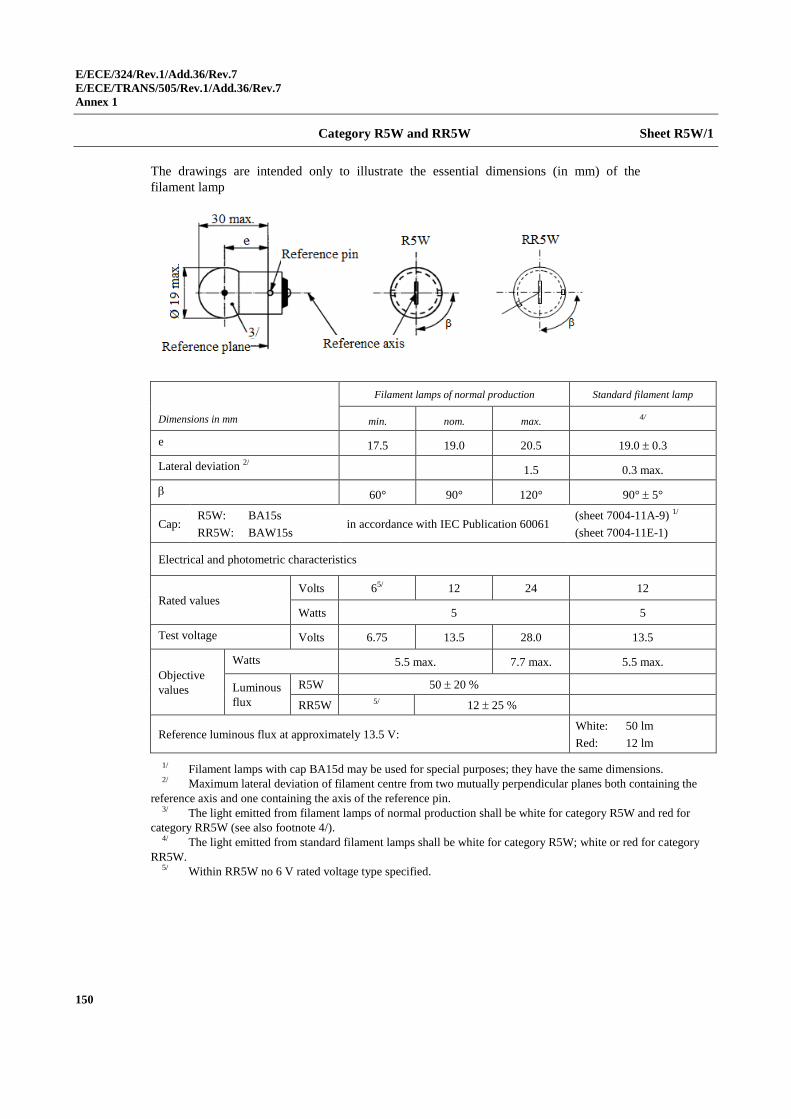
E/ECE/324/Rev.1/Add.36/Rev.7
E/ECE/TRANS/505/Rev.1/Add.36/Rev.7
Annex 1
150
Category R5W and RR5W Sheet R5W/1
The drawings are intended only to illustrate the essential dimensions (in mm) of the
filament lamp
Dimensions in mm
Filament lamps of normal production Standard filament lamp
min. nom. max. 4/
e 17.5 19.0 20.5 19.0 0.3
Lateral deviation 2/ 1.5 0.3 max.
60° 90° 120° 90° 5°
Cap: R5W: BA15s
RR5W: BAW15s in accordance with IEC Publication 60061
(sheet 7004-11A-9) 1/
(sheet 7004-11E-1)
Electrical and photometric characteristics
Rated values Volts 65/ 12 24 12
Watts 5 5
Test voltage Volts 6.75 13.5 28.0 13.5
Objective
values
Watts 5.5 max. 7.7 max. 5.5 max.
Luminous
flux
R5W 50 20 %
RR5W 5/ 12 25 %
Reference luminous flux at approximately 13.5 V: White: 50 lm
Red: 12 lm
1/ Filament lamps with cap BA15d may be used for special purposes; they have the same dimensions. 2/ Maximum lateral deviation of filament centre from two mutually perpendicular planes both containing the
reference axis and one containing the axis of the reference pin. 3/ The light emitted from filament lamps of normal production shall be white for category R5W and red for
category RR5W (see also footnote 4/). 4/ The light emitted from standard filament lamps shall be white for category R5W; white or red for category
RR5W. 5/ Within RR5W no 6 V rated voltage type specified.
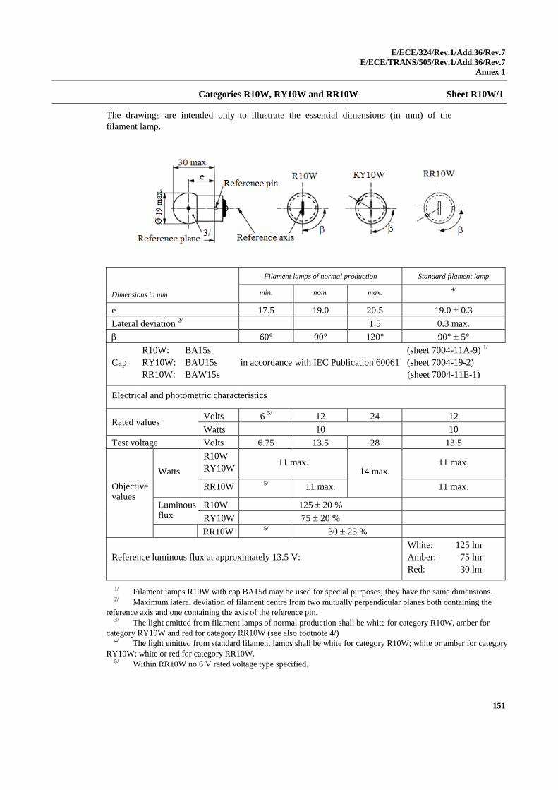
E/ECE/324/Rev.1/Add.36/Rev.7
E/ECE/TRANS/505/Rev.1/Add.36/Rev.7
Annex 1
151
Categories R10W, RY10W and RR10W Sheet R10W/1
The drawings are intended only to illustrate the essential dimensions (in mm) of the
filament lamp.
Dimensions in mm
Filament lamps of normal production Standard filament lamp
min. nom. max. 4/
e 17.5 19.0 20.5 19.0 0.3
Lateral deviation 2/
1.5 0.3 max.
60° 90° 120° 90° 5°
Cap
R10W: BA15s
RY10W: BAU15s
RR10W: BAW15s
in accordance with IEC Publication 60061
(sheet 7004-11A-9) 1/
(sheet 7004-19-2)
(sheet 7004-11E-1)
Electrical and photometric characteristics
Rated values Volts 6
5/ 12 24 12
Watts 10 10
Test voltage Volts 6.75 13.5 28 13.5
Objective values
Watts
R10W
RY10W 11 max.
14 max. 11 max.
RR10W 5/
11 max. 11 max.
Luminous flux
R10W 125 20 %
RY10W 75 20 %
RR10W 5/
30 25 %
Reference luminous flux at approximately 13.5 V:
White: 125 lm
Amber: 75 lm
Red: 30 lm
1/ Filament lamps R10W with cap BA15d may be used for special purposes; they have the same dimensions. 2/ Maximum lateral deviation of filament centre from two mutually perpendicular planes both containing the
reference axis and one containing the axis of the reference pin. 3/ The light emitted from filament lamps of normal production shall be white for category R10W, amber for
category RY10W and red for category RR10W (see also footnote 4/) 4/ The light emitted from standard filament lamps shall be white for category R10W; white or amber for category
RY10W; white or red for category RR10W. 5/ Within RR10W no 6 V rated voltage type specified.
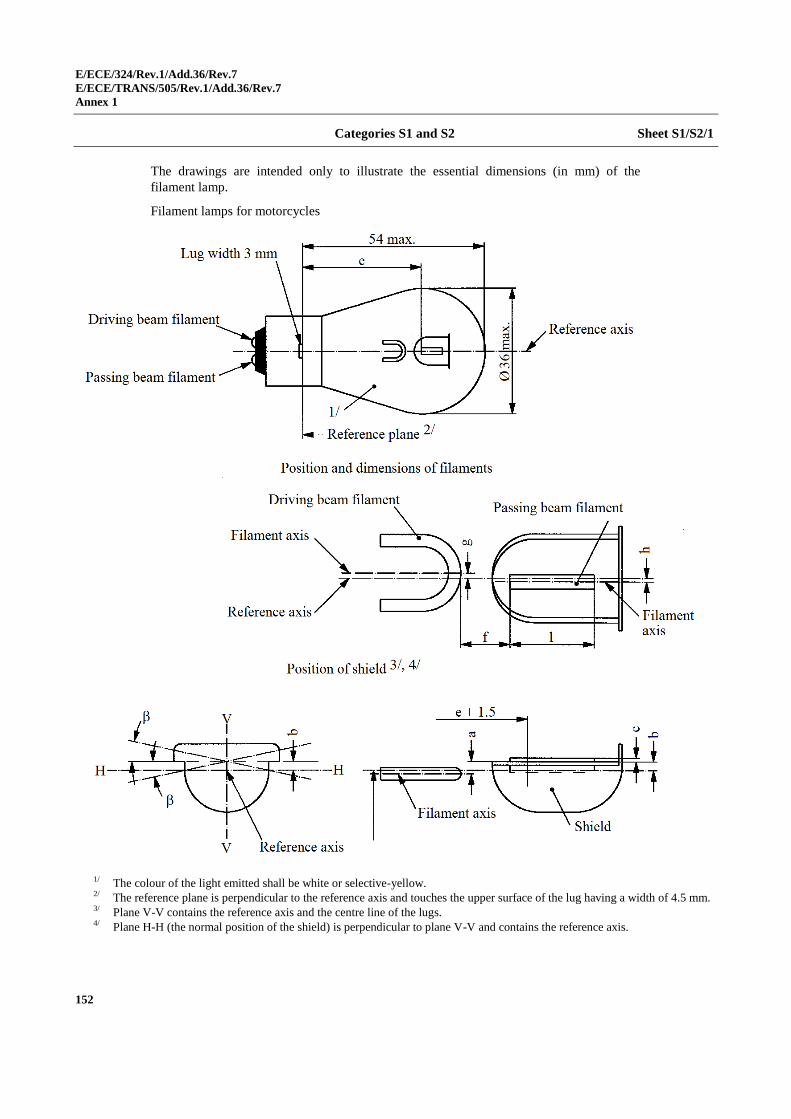
E/ECE/324/Rev.1/Add.36/Rev.7
E/ECE/TRANS/505/Rev.1/Add.36/Rev.7
Annex 1
152
Categories S1 and S2 Sheet S1/S2/1
The drawings are intended only to illustrate the essential dimensions (in mm) of the
filament lamp.
Filament lamps for motorcycles
1/ The colour of the light emitted shall be white or selective-yellow. 2/ The reference plane is perpendicular to the reference axis and touches the upper surface of the lug having a width of 4.5 mm. 3/ Plane V-V contains the reference axis and the centre line of the lugs. 4/ Plane H-H (the normal position of the shield) is perpendicular to plane V-V and contains the reference axis.
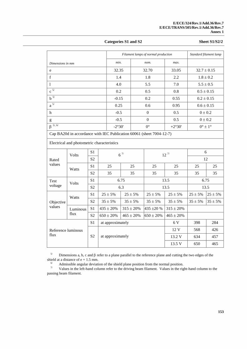
E/ECE/324/Rev.1/Add.36/Rev.7
E/ECE/TRANS/505/Rev.1/Add.36/Rev.7
Annex 1
153
Categories S1 and S2 Sheet S1/S2/2
Dimensions in mm
Filament lamps of normal production Standard filament lamp
min. nom. max.
e 32.35 32.70 33.05 32.7 0.15
f 1.4 1.8 2.2 1.8 0.2
l 4.0 5.5 7.0 5.5 0.5
c 5/
0.2 0.5 0.8 0.5 0.15
b 5/
-0.15 0.2 0.55 0.2 0.15
a 5/
0.25 0.6 0.95 0.6 0.15
h -0.5 0 0.5 0 0.2
g -0.5 0 0.5 0 0.2
5/, 6/
-2°30' 0° +2°30' 0° 1°
Cap BA20d in accordance with IEC Publication 60061 (sheet 7004-12-7)
Electrical and photometric characteristics
Rated values
Volts S1
6 7/
12 7/
6
S2 12
Watts S1 25 25 25 25 25 25
S2 35 35 35 35 35 35
Test voltage
Volts S1 6.75 13.5 6.75
S2 6.3 13.5 13.5
Objective values
Watts S1 25 5% 25 5% 25 5% 25 5% 25 5% 25 5%
S2 35 5% 35 5% 35 5% 35 5% 35 5% 35 5%
Luminous flux
S1 435 20% 315 20% 435 20 % 315 20%
S2 650 20% 465 20% 650 20% 465 20%
Reference luminous flux
S1 at approximately 6 V 398 284
S2 at approximately
12 V 568 426
13.2 V 634 457
13.5 V 650 465
5/ Dimensions a, b, c and refer to a plane parallel to the reference plane and cutting the two edges of the
shield at a distance of e + 1.5 mm. 6/ Admissible angular deviation of the shield plane position from the normal position. 7/ Values in the left-hand column refer to the driving beam filament. Values in the right-hand column to the
passing beam filament.
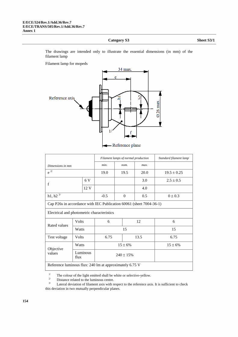
E/ECE/324/Rev.1/Add.36/Rev.7
E/ECE/TRANS/505/Rev.1/Add.36/Rev.7
Annex 1
154
Category S3 Sheet S3/1
The drawings are intended only to illustrate the essential dimensions (in mm) of the
filament lamp
Filament lamp for mopeds
Dimensions in mm
Filament lamps of normal production Standard filament lamp
min. nom. max.
e 2/
19.0 19.5 20.0 19.5 0.25
f 6 V 3.0 2.5 0.5
12 V 4.0
h1, h2 3/
-0.5 0 0.5 0 0.3
Cap P26s in accordance with IEC Publication 60061 (sheet 7004-36-1)
Electrical and photometric characteristics
Rated values Volts 6 12 6
Watts 15 15
Test voltage Volts 6.75 13.5 6.75
Objective values
Watts 15 6% 15 6%
Luminous flux
240 15%
Reference luminous flux: 240 lm at approximately 6.75 V
1/ The colour of the light emitted shall be white or selective-yellow. 2/ Distance related to the luminous centre. 3/ Lateral deviation of filament axis with respect to the reference axis. It is sufficient to check
this deviation in two mutually perpendicular planes.
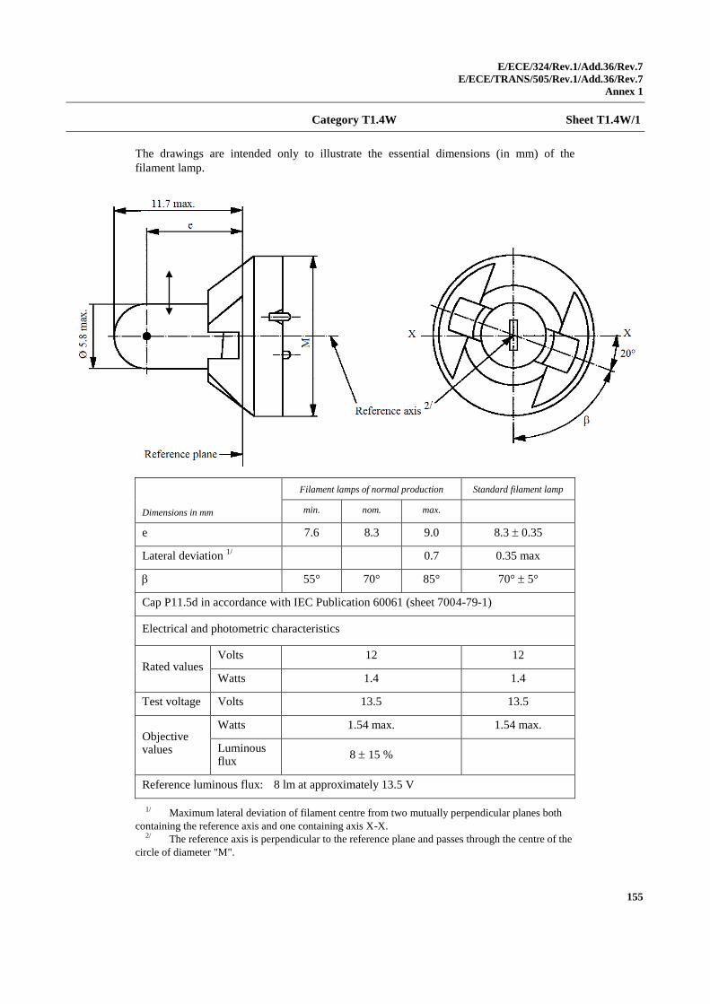
E/ECE/324/Rev.1/Add.36/Rev.7
E/ECE/TRANS/505/Rev.1/Add.36/Rev.7
Annex 1
155
Category T1.4W Sheet T1.4W/1
The drawings are intended only to illustrate the essential dimensions (in mm) of the
filament lamp.
Dimensions in mm
Filament lamps of normal production Standard filament lamp
min. nom. max.
e 7.6 8.3 9.0 8.3 0.35
Lateral deviation 1/
0.7 0.35 max
55° 70° 85° 70° 5°
Cap P11.5d in accordance with IEC Publication 60061 (sheet 7004-79-1)
Electrical and photometric characteristics
Rated values Volts 12 12
Watts 1.4 1.4
Test voltage Volts 13.5 13.5
Objective values
Watts 1.54 max. 1.54 max.
Luminous flux
8 15 %
Reference luminous flux: 8 lm at approximately 13.5 V
1/ Maximum lateral deviation of filament centre from two mutually perpendicular planes both
containing the reference axis and one containing axis X-X. 2/ The reference axis is perpendicular to the reference plane and passes through the centre of the
circle of diameter "M".
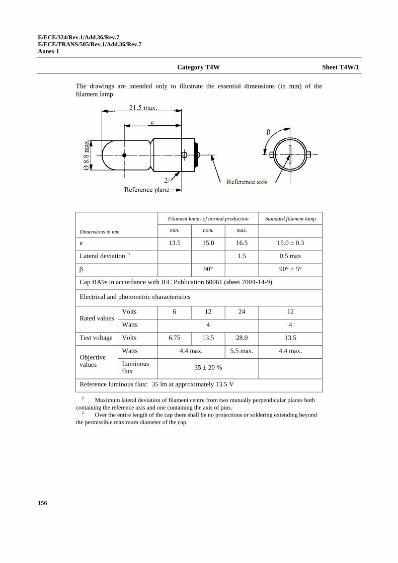
E/ECE/324/Rev.1/Add.36/Rev.7
E/ECE/TRANS/505/Rev.1/Add.36/Rev.7
Annex 1
156
Category T4W Sheet T4W/1
The drawings are intended only to illustrate the essential dimensions (in mm) of the
filament lamp.
Dimensions in mm
Filament lamps of normal production Standard filament lamp
min. nom. max.
e 13.5 15.0 16.5 15.0 0.3
Lateral deviation 1/
1.5 0.5 max
90° 90° 5°
Cap BA9s in accordance with IEC Publication 60061 (sheet 7004-14-9)
Electrical and photometric characteristics
Rated values Volts 6 12 24 12
Watts 4 4
Test voltage Volts 6.75 13.5 28.0 13.5
Objective values
Watts 4.4 max. 5.5 max. 4.4 max.
Luminous flux
35 20 %
Reference luminous flux: 35 lm at approximately 13.5 V
1/ Maximum lateral deviation of filament centre from two mutually perpendicular planes both
containing the reference axis and one containing the axis of pins. 2/ Over the entire length of the cap there shall be no projections or soldering extending beyond
the permissible maximum diameter of the cap.
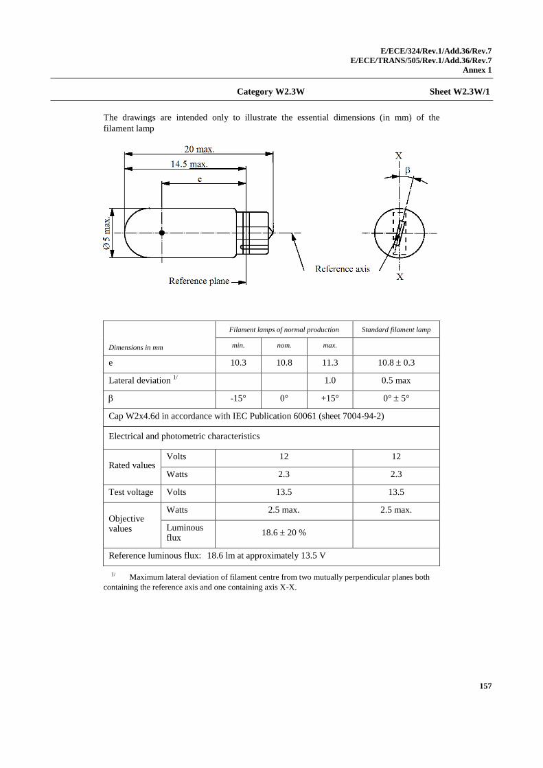
E/ECE/324/Rev.1/Add.36/Rev.7
E/ECE/TRANS/505/Rev.1/Add.36/Rev.7
Annex 1
157
Category W2.3W Sheet W2.3W/1
The drawings are intended only to illustrate the essential dimensions (in mm) of the
filament lamp
Dimensions in mm
Filament lamps of normal production Standard filament lamp
min. nom. max.
e 10.3 10.8 11.3 10.8 0.3
Lateral deviation 1/
1.0 0.5 max
-15° 0° +15° 0° 5°
Cap W2x4.6d in accordance with IEC Publication 60061 (sheet 7004-94-2)
Electrical and photometric characteristics
Rated values Volts 12 12
Watts 2.3 2.3
Test voltage Volts 13.5 13.5
Objective values
Watts 2.5 max. 2.5 max.
Luminous flux
18.6 20 %
Reference luminous flux: 18.6 lm at approximately 13.5 V
1/ Maximum lateral deviation of filament centre from two mutually perpendicular planes both
containing the reference axis and one containing axis X-X.
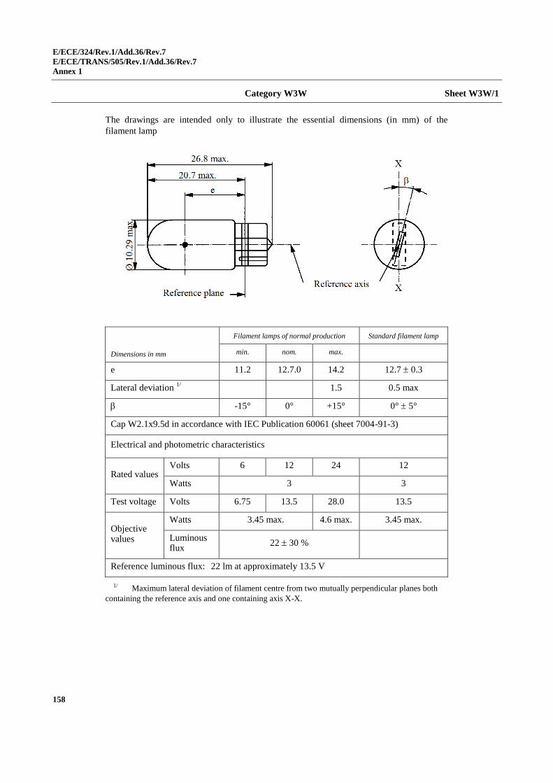
E/ECE/324/Rev.1/Add.36/Rev.7
E/ECE/TRANS/505/Rev.1/Add.36/Rev.7
Annex 1
158
Category W3W Sheet W3W/1
The drawings are intended only to illustrate the essential dimensions (in mm) of the
filament lamp
Dimensions in mm
Filament lamps of normal production Standard filament lamp
min. nom. max.
e 11.2 12.7.0 14.2 12.7 0.3
Lateral deviation 1/
1.5 0.5 max
-15° 0° +15° 0° 5°
Cap W2.1x9.5d in accordance with IEC Publication 60061 (sheet 7004-91-3)
Electrical and photometric characteristics
Rated values Volts 6 12 24 12
Watts 3 3
Test voltage Volts 6.75 13.5 28.0 13.5
Objective values
Watts 3.45 max. 4.6 max. 3.45 max.
Luminous flux
22 30 %
Reference luminous flux: 22 lm at approximately 13.5 V
1/ Maximum lateral deviation of filament centre from two mutually perpendicular planes both
containing the reference axis and one containing axis X-X.
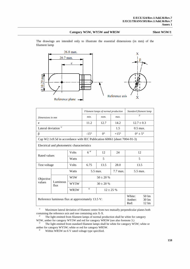
E/ECE/324/Rev.1/Add.36/Rev.7
E/ECE/TRANS/505/Rev.1/Add.36/Rev.7
Annex 1
159
Category W5W, WY5W and WR5W Sheet W5W/1
The drawings are intended only to illustrate the essential dimensions (in mm) of the
filament lamp
Dimensions in mm
Filament lamps of normal production Standard filament lamp
min. nom. max. 3/
e 11.2 12.7 14.2 12.7 0.3
Lateral deviation 1/
1.5 0.5 max.
-15° 0° +15° 0° 5°
Cap W2.1x9.5d in accordance with IEC Publication 60061 (sheet 7004-91-3)
Electrical and photometric characteristics
Rated values Volts 6
4/ 12 24 12
Watts 5 5
Test voltage Volts 6.75 13.5 28.0 13.5
Objective values
Watts 5.5 max. 7.7 max. 5.5 max.
Luminous flux
W5W 50 20 %
WY5W 30 20 %
WR5W 4/
12 25 %
Reference luminous flux at approximately 13.5 V: White: 50 lm Amber: 30 lm Red: 12 lm
1/ Maximum lateral deviation of filament centre from two mutually perpendicular planes both
containing the reference axis and one containing axis X-X. 2/ The light emitted from filament lamps of normal production shall be white for category
W5W, amber for category WY5W and red for category WR5W (see also footnote 3.) 3/ The light emitted from standard filament lamps shall be white for category W5W; white or
amber for category WY5W; white or red for category WR5W. 4/ Within WR5W no 6 V rated voltage type specified.
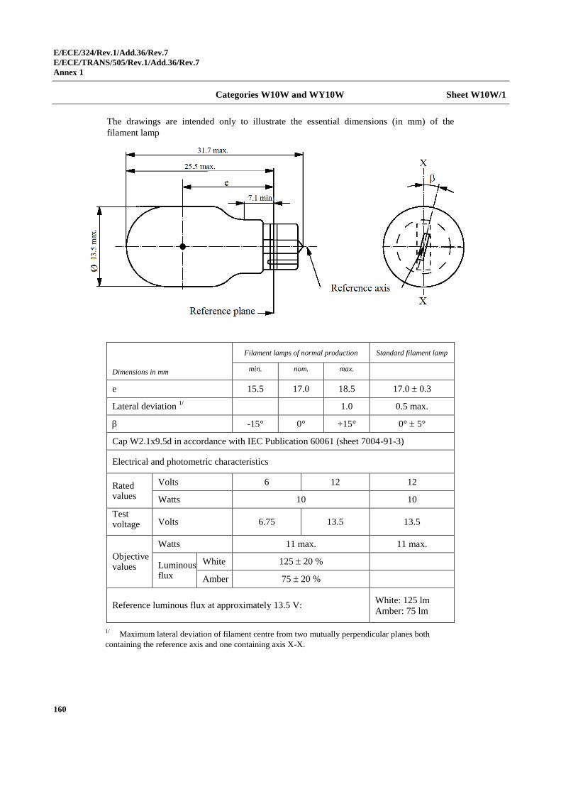
E/ECE/324/Rev.1/Add.36/Rev.7
E/ECE/TRANS/505/Rev.1/Add.36/Rev.7
Annex 1
160
Categories W10W and WY10W Sheet W10W/1
The drawings are intended only to illustrate the essential dimensions (in mm) of the
filament lamp
Dimensions in mm
Filament lamps of normal production Standard filament lamp
min. nom. max.
e 15.5 17.0 18.5 17.0 0.3
Lateral deviation 1/
1.0 0.5 max.
-15° 0° +15° 0° 5°
Cap W2.1x9.5d in accordance with IEC Publication 60061 (sheet 7004-91-3)
Electrical and photometric characteristics
Rated values
Volts 6 12 12
Watts 10 10
Test voltage Volts 6.75 13.5 13.5
Objective values
Watts 11 max. 11 max.
Luminous flux
White 125 20 %
Amber 75 20 %
Reference luminous flux at approximately 13.5 V: White: 125 lm
Amber: 75 lm
1/ Maximum lateral deviation of filament centre from two mutually perpendicular planes both
containing the reference axis and one containing axis X-X.
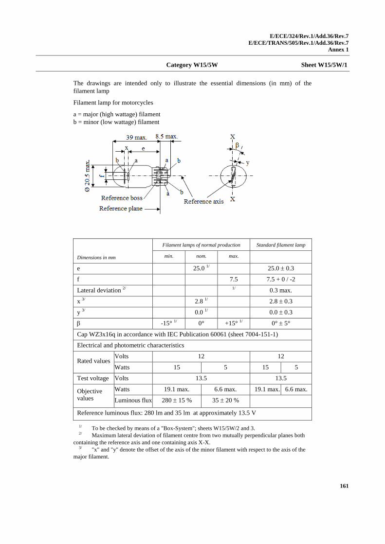
E/ECE/324/Rev.1/Add.36/Rev.7
E/ECE/TRANS/505/Rev.1/Add.36/Rev.7
Annex 1
161
Category W15/5W Sheet W15/5W/1
The drawings are intended only to illustrate the essential dimensions (in mm) of the
filament lamp
Filament lamp for motorcycles
a = major (high wattage) filament
b = minor (low wattage) filament
Dimensions in mm
Filament lamps of normal production Standard filament lamp
min. nom. max.
e 25.0 1/ 25.0 0.3
f 7.5 7.5 + 0 / -2
Lateral deviation 2/
1/
0.3 max.
x 3/
2.8 1/ 2.8 0.3
y 3/
0.0 1/ 0.0 0.3
-15° 1/
0° +15° 1/
0° 5°
Cap WZ3x16q in accordance with IEC Publication 60061 (sheet 7004-151-1)
Electrical and photometric characteristics
Rated values Volts 12 12
Watts 15 5 15 5
Test voltage Volts 13.5 13.5
Objective values
Watts 19.1 max. 6.6 max. 19.1 max. 6.6 max.
Luminous flux 280 15 % 35 20 %
Reference luminous flux: 280 lm and 35 lm at approximately 13.5 V
1/ To be checked by means of a "Box-System"; sheets W15/5W/2 and 3. 2/ Maximum lateral deviation of filament centre from two mutually perpendicular planes both
containing the reference axis and one containing axis X-X. 3/ "x" and "y" denote the offset of the axis of the minor filament with respect to the axis of the
major filament.
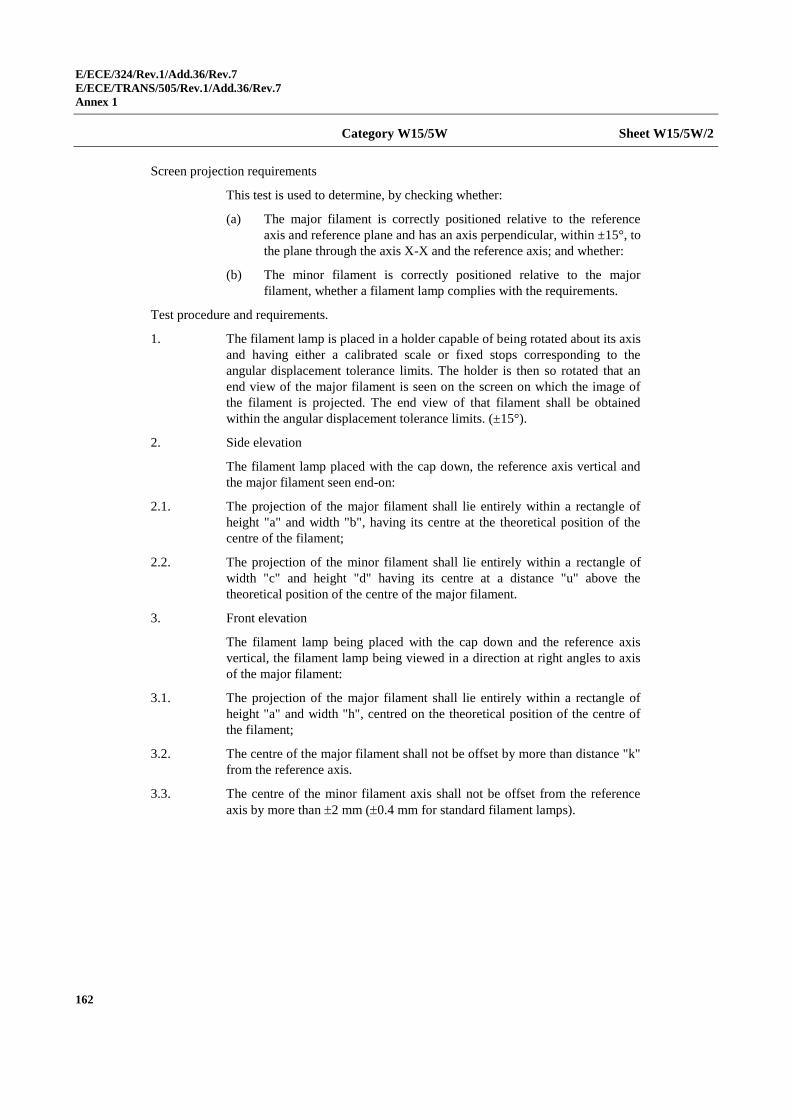
E/ECE/324/Rev.1/Add.36/Rev.7
E/ECE/TRANS/505/Rev.1/Add.36/Rev.7
Annex 1
162
Category W15/5W Sheet W15/5W/2
Screen projection requirements
This test is used to determine, by checking whether:
(a) The major filament is correctly positioned relative to the reference
axis and reference plane and has an axis perpendicular, within ±15°, to
the plane through the axis X-X and the reference axis; and whether:
(b) The minor filament is correctly positioned relative to the major
filament, whether a filament lamp complies with the requirements.
Test procedure and requirements.
1. The filament lamp is placed in a holder capable of being rotated about its axis
and having either a calibrated scale or fixed stops corresponding to the
angular displacement tolerance limits. The holder is then so rotated that an
end view of the major filament is seen on the screen on which the image of
the filament is projected. The end view of that filament shall be obtained
within the angular displacement tolerance limits. (±15°).
2. Side elevation
The filament lamp placed with the cap down, the reference axis vertical and
the major filament seen end-on:
2.1. The projection of the major filament shall lie entirely within a rectangle of
height "a" and width "b", having its centre at the theoretical position of the
centre of the filament;
2.2. The projection of the minor filament shall lie entirely within a rectangle of
width "c" and height "d" having its centre at a distance "u" above the
theoretical position of the centre of the major filament.
3. Front elevation
The filament lamp being placed with the cap down and the reference axis
vertical, the filament lamp being viewed in a direction at right angles to axis
of the major filament:
3.1. The projection of the major filament shall lie entirely within a rectangle of
height "a" and width "h", centred on the theoretical position of the centre of
the filament;
3.2. The centre of the major filament shall not be offset by more than distance "k"
from the reference axis.
3.3. The centre of the minor filament axis shall not be offset from the reference
axis by more than 2 mm (0.4 mm for standard filament lamps).
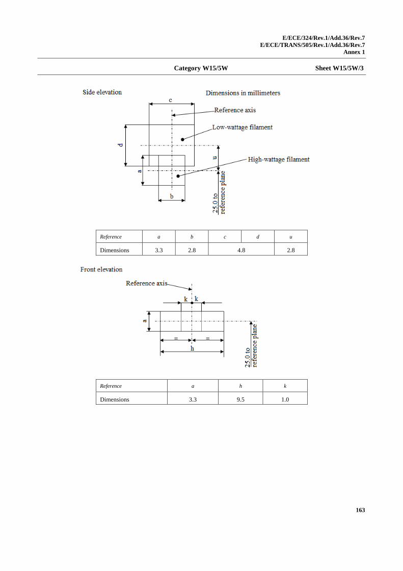
E/ECE/324/Rev.1/Add.36/Rev.7
E/ECE/TRANS/505/Rev.1/Add.36/Rev.7
Annex 1
163
Category W15/5W Sheet W15/5W/3
Reference a b c d u
Dimensions 3.3 2.8 4.8 2.8
Reference a h k
Dimensions 3.3 9.5 1.0
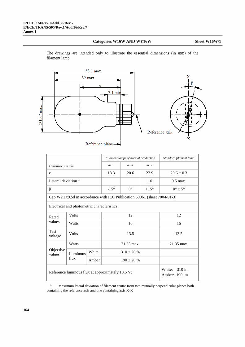
E/ECE/324/Rev.1/Add.36/Rev.7
E/ECE/TRANS/505/Rev.1/Add.36/Rev.7
Annex 1
164
Categories W16W AND WY16W Sheet W16W/1
The drawings are intended only to illustrate the essential dimensions (in mm) of the
filament lamp
Dimensions in mm
Filament lamps of normal production Standard filament lamp
min. nom. max.
e 18.3 20.6 22.9 20.6 0.3
Lateral deviation 1/
1.0 0.5 max.
-15° 0° +15° 0° 5°
Cap W2.1x9.5d in accordance with IEC Publication 60061 (sheet 7004-91-3)
Electrical and photometric characteristics
Rated values
Volts 12 12
Watts 16 16
Test voltage
Volts 13.5 13.5
Objective values
Watts 21.35 max. 21.35 max.
Luminous flux
White 310 20 %
Amber 190 20 %
Reference luminous flux at approximately 13.5 V: White: 310 lm
Amber: 190 lm
1/ Maximum lateral deviation of filament centre from two mutually perpendicular planes both
containing the reference axis and one containing axis X-X
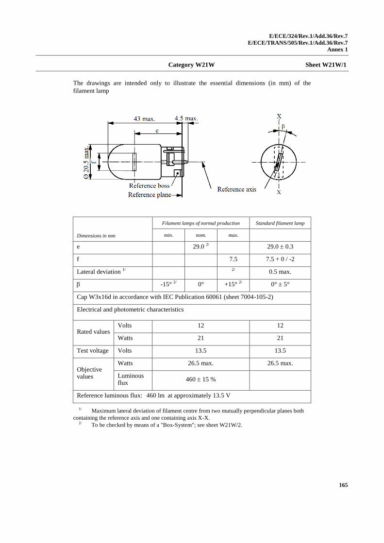
E/ECE/324/Rev.1/Add.36/Rev.7
E/ECE/TRANS/505/Rev.1/Add.36/Rev.7
Annex 1
165
Category W21W Sheet W21W/1
The drawings are intended only to illustrate the essential dimensions (in mm) of the
filament lamp
Dimensions in mm
Filament lamps of normal production Standard filament lamp
min. nom. max.
e 29.0 2/ 29.0 0.3
f 7.5 7.5 + 0 / -2
Lateral deviation 1/
2/
0.5 max.
-15° 2/
0° +15° 2/
0° 5°
Cap W3x16d in accordance with IEC Publication 60061 (sheet 7004-105-2)
Electrical and photometric characteristics
Rated values Volts 12 12
Watts 21 21
Test voltage Volts 13.5 13.5
Objective values
Watts 26.5 max. 26.5 max.
Luminous flux
460 15 %
Reference luminous flux: 460 lm at approximately 13.5 V
1/ Maximum lateral deviation of filament centre from two mutually perpendicular planes both
containing the reference axis and one containing axis X-X. 2/ To be checked by means of a "Box-System"; see sheet W21W/2.
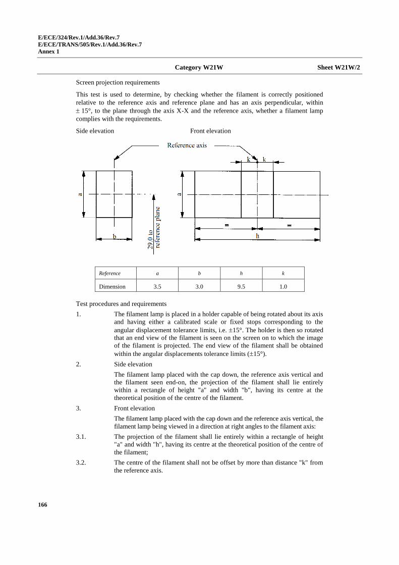
E/ECE/324/Rev.1/Add.36/Rev.7
E/ECE/TRANS/505/Rev.1/Add.36/Rev.7
Annex 1
166
Category W21W Sheet W21W/2
Screen projection requirements
This test is used to determine, by checking whether the filament is correctly positioned
relative to the reference axis and reference plane and has an axis perpendicular, within
15°, to the plane through the axis X-X and the reference axis, whether a filament lamp
complies with the requirements.
Side elevation Front elevation
Reference a b h k
Dimension 3.5 3.0 9.5 1.0
Test procedures and requirements
1. The filament lamp is placed in a holder capable of being rotated about its axis
and having either a calibrated scale or fixed stops corresponding to the
angular displacement tolerance limits, i.e. 15°. The holder is then so rotated
that an end view of the filament is seen on the screen on to which the image
of the filament is projected. The end view of the filament shall be obtained
within the angular displacements tolerance limits (15°).
2. Side elevation
The filament lamp placed with the cap down, the reference axis vertical and
the filament seen end-on, the projection of the filament shall lie entirely
within a rectangle of height "a" and width "b", having its centre at the
theoretical position of the centre of the filament.
3. Front elevation
The filament lamp placed with the cap down and the reference axis vertical, the
filament lamp being viewed in a direction at right angles to the filament axis:
3.1. The projection of the filament shall lie entirely within a rectangle of height
"a" and width "h", having its centre at the theoretical position of the centre of
the filament;
3.2. The centre of the filament shall not be offset by more than distance "k" from
the reference axis.
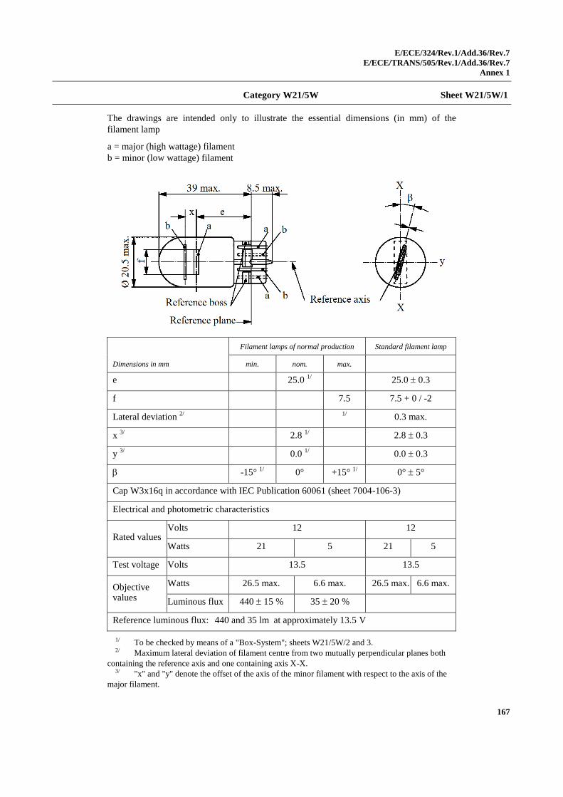
E/ECE/324/Rev.1/Add.36/Rev.7
E/ECE/TRANS/505/Rev.1/Add.36/Rev.7
Annex 1
167
Category W21/5W Sheet W21/5W/1
The drawings are intended only to illustrate the essential dimensions (in mm) of the
filament lamp
a = major (high wattage) filament
b = minor (low wattage) filament
Dimensions in mm
Filament lamps of normal production Standard filament lamp
min. nom. max.
e 25.0 1/ 25.0 0.3
f 7.5 7.5 + 0 / -2
Lateral deviation 2/
1/
0.3 max.
x 3/
2.8 1/ 2.8 0.3
y 3/
0.0 1/ 0.0 0.3
-15° 1/
0° +15° 1/
0° 5°
Cap W3x16q in accordance with IEC Publication 60061 (sheet 7004-106-3)
Electrical and photometric characteristics
Rated values Volts 12 12
Watts 21 5 21 5
Test voltage Volts 13.5 13.5
Objective values
Watts 26.5 max. 6.6 max. 26.5 max. 6.6 max.
Luminous flux 440 15 % 35 20 %
Reference luminous flux: 440 and 35 lm at approximately 13.5 V
1/ To be checked by means of a "Box-System"; sheets W21/5W/2 and 3. 2/ Maximum lateral deviation of filament centre from two mutually perpendicular planes both
containing the reference axis and one containing axis X-X. 3/ "x" and "y" denote the offset of the axis of the minor filament with respect to the axis of the
major filament.

E/ECE/324/Rev.1/Add.36/Rev.7
E/ECE/TRANS/505/Rev.1/Add.36/Rev.7
Annex 1
168
Category W21/5W Sheet W21/5W/2
Screen projection requirements
This test is used to determine, by checking whether:
(a) The major filament is correctly positioned relative to the reference
axis and reference plane and has an axis perpendicular, within ±15°, to
the plane through the axis X-X and the reference axis; and whether:
(b) The minor filament is correctly positioned relative to the major
filament, whether a filament lamp complies with the requirements.
Test procedure and requirements.
1. The filament lamp is placed in a holder capable of being rotated about its axis
and having either a calibrated scale or fixed stops corresponding to the
angular displacement tolerance limits. The holder is then so rotated that an
end view of the major filament is seen on the screen on which the image of
the filament is projected. The end view of that filament shall be obtained
within the angular displacement tolerance limits (±15°).
2. Side elevation
The filament lamp placed with the cap down, the reference axis vertical and
the major filament seen end-on:
2.1. The projection of the major filament shall lie entirely within a rectangle of
height "a" and width "b", having its centre at the theoretical position of the
centre of the filament;
2.2. The projection of the minor filament shall lie entirely within a rectangle of
width "c" and height "d" having its centre at a distance "u" above the
theoretical position of the centre of the major filament.
3. Front elevation
The filament lamp being placed with the cap down and the reference axis
vertical, the filament lamp being viewed in a direction at right angles to axis
of the major filament:
3.1. The projection of the major filament shall lie entirely within a rectangle of
height "a" and width "h", centred on the theoretical position of the centre of
the filament;
3.2. The centre of the major filament shall not be offset by more than distance "k"
from the reference axis;
3.3. The centre of the minor filament axis shall not be offset from the reference
axis by more than 2 mm (0.4 mm for standard filament lamps).
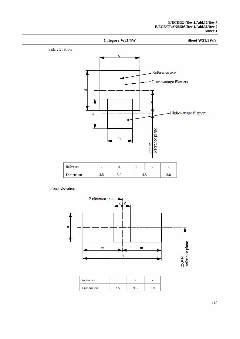
E/ECE/324/Rev.1/Add.36/Rev.7
E/ECE/TRANS/505/Rev.1/Add.36/Rev.7
Annex 1
169
Category W21/5W Sheet W21/5W/3
Reference a b c d u
Dimension 3.5 3.0 4.8 2.8
Reference a h k
Dimension 3.5 9.5 1.0
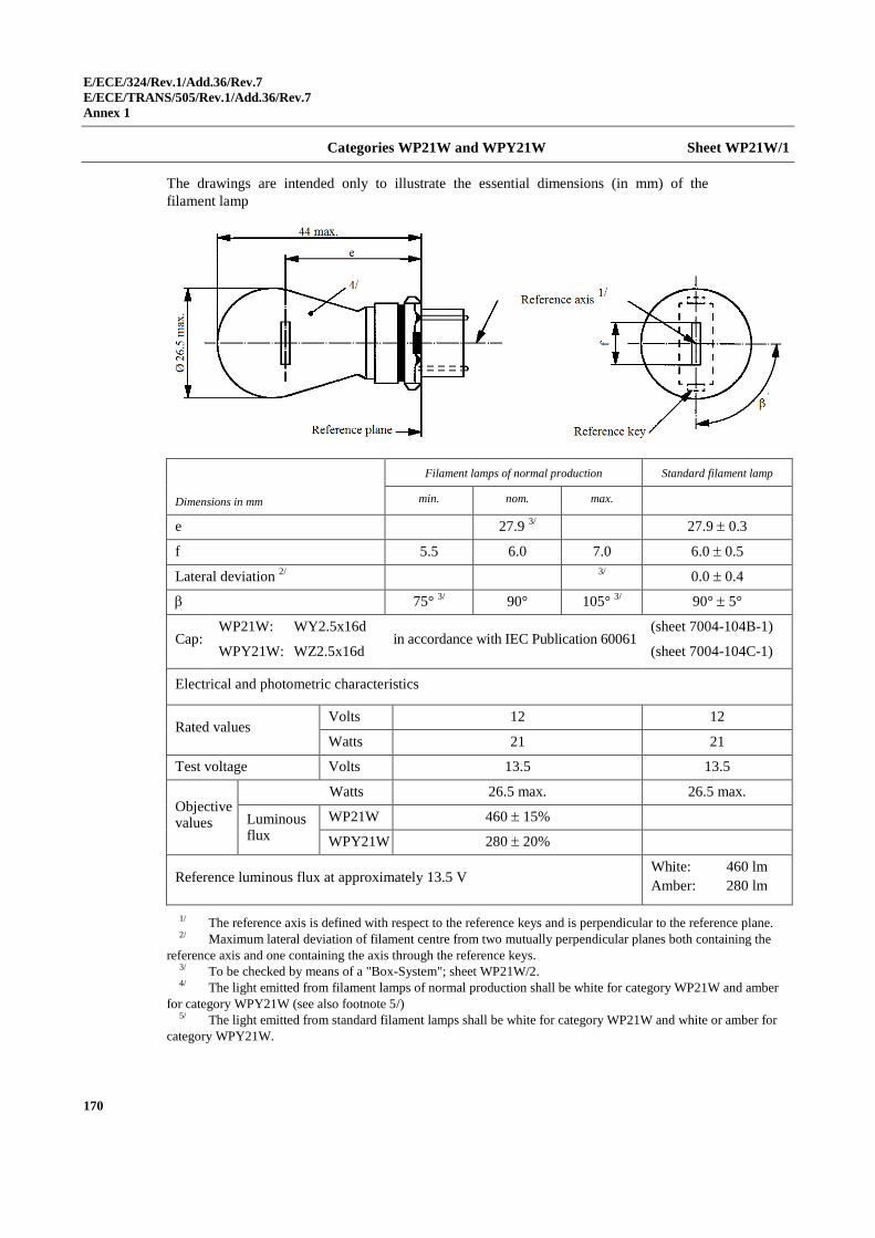
E/ECE/324/Rev.1/Add.36/Rev.7
E/ECE/TRANS/505/Rev.1/Add.36/Rev.7
Annex 1
170
Categories WP21W and WPY21W Sheet WP21W/1
The drawings are intended only to illustrate the essential dimensions (in mm) of the
filament lamp
Dimensions in mm
Filament lamps of normal production Standard filament lamp
min. nom. max.
e 27.9 3/ 27.9 0.3
f 5.5 6.0 7.0 6.0 0.5
Lateral deviation 2/
3/
0.0 0.4
75° 3/
90° 105° 3/ 90° 5°
Cap: WP21W: WY2.5x16d
WPY21W: WZ2.5x16d in accordance with IEC Publication 60061
(sheet 7004-104B-1)
(sheet 7004-104C-1)
Electrical and photometric characteristics
Rated values Volts 12 12
Watts 21 21
Test voltage Volts 13.5 13.5
Objective values
Watts 26.5 max. 26.5 max.
Luminous flux
WP21W 460 15%
WPY21W 280 20%
Reference luminous flux at approximately 13.5 V White: 460 lm
Amber: 280 lm
1/ The reference axis is defined with respect to the reference keys and is perpendicular to the reference plane. 2/ Maximum lateral deviation of filament centre from two mutually perpendicular planes both containing the
reference axis and one containing the axis through the reference keys. 3/ To be checked by means of a "Box-System"; sheet WP21W/2. 4/ The light emitted from filament lamps of normal production shall be white for category WP21W and amber
for category WPY21W (see also footnote 5/) 5/ The light emitted from standard filament lamps shall be white for category WP21W and white or amber for
category WPY21W.
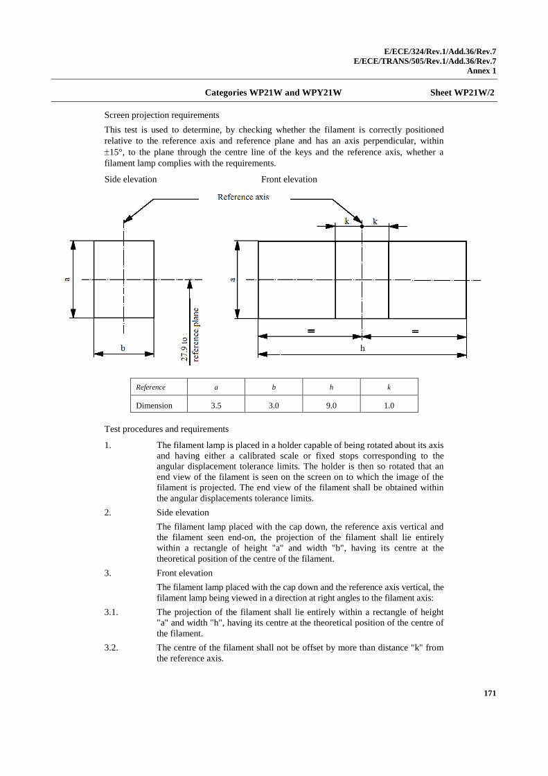
E/ECE/324/Rev.1/Add.36/Rev.7
E/ECE/TRANS/505/Rev.1/Add.36/Rev.7
Annex 1
171
Categories WP21W and WPY21W Sheet WP21W/2
Screen projection requirements
This test is used to determine, by checking whether the filament is correctly positioned
relative to the reference axis and reference plane and has an axis perpendicular, within
15°, to the plane through the centre line of the keys and the reference axis, whether a
filament lamp complies with the requirements.
Side elevation Front elevation
Reference a b h k
Dimension 3.5 3.0 9.0 1.0
Test procedures and requirements
1. The filament lamp is placed in a holder capable of being rotated about its axis
and having either a calibrated scale or fixed stops corresponding to the
angular displacement tolerance limits. The holder is then so rotated that an
end view of the filament is seen on the screen on to which the image of the
filament is projected. The end view of the filament shall be obtained within
the angular displacements tolerance limits.
2. Side elevation
The filament lamp placed with the cap down, the reference axis vertical and
the filament seen end-on, the projection of the filament shall lie entirely
within a rectangle of height "a" and width "b", having its centre at the
theoretical position of the centre of the filament.
3. Front elevation
The filament lamp placed with the cap down and the reference axis vertical, the
filament lamp being viewed in a direction at right angles to the filament axis:
3.1. The projection of the filament shall lie entirely within a rectangle of height
"a" and width "h", having its centre at the theoretical position of the centre of
the filament.
3.2. The centre of the filament shall not be offset by more than distance "k" from
the reference axis.
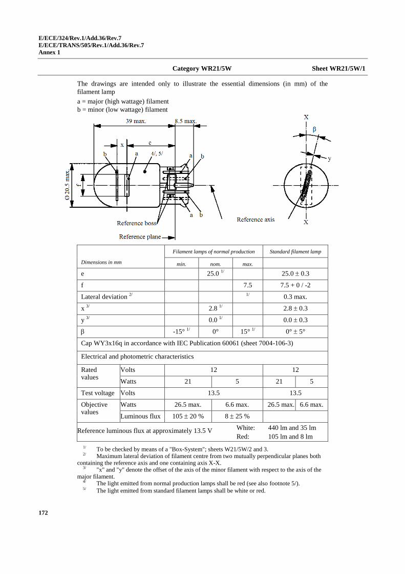
E/ECE/324/Rev.1/Add.36/Rev.7
E/ECE/TRANS/505/Rev.1/Add.36/Rev.7
Annex 1
172
Category WR21/5W Sheet WR21/5W/1
The drawings are intended only to illustrate the essential dimensions (in mm) of the
filament lamp
a = major (high wattage) filament
b = minor (low wattage) filament
Dimensions in mm
Filament lamps of normal production Standard filament lamp
min. nom. max.
e 25.0 1/ 25.0 0.3
f 7.5 7.5 + 0 / -2
Lateral deviation 2/
1/
0.3 max.
x 3/
2.8 1/ 2.8 0.3
y 3/
0.0 1/ 0.0 0.3
-15° 1/
0° 15° 1/
0° 5°
Cap WY3x16q in accordance with IEC Publication 60061 (sheet 7004-106-3)
Electrical and photometric characteristics
Rated values
Volts 12 12
Watts 21 5 21 5
Test voltage Volts 13.5 13.5
Objective values
Watts 26.5 max. 6.6 max. 26.5 max. 6.6 max.
Luminous flux 105 20 % 8 25 %
Reference luminous flux at approximately 13.5 V White: 440 lm and 35 lm
Red: 105 lm and 8 lm
1/ To be checked by means of a "Box-System"; sheets W21/5W/2 and 3. 2/ Maximum lateral deviation of filament centre from two mutually perpendicular planes both
containing the reference axis and one containing axis X-X. 3/ "x" and "y" denote the offset of the axis of the minor filament with respect to the axis of the
major filament. 4/ The light emitted from normal production lamps shall be red (see also footnote 5/). 5/ The light emitted from standard filament lamps shall be white or red.
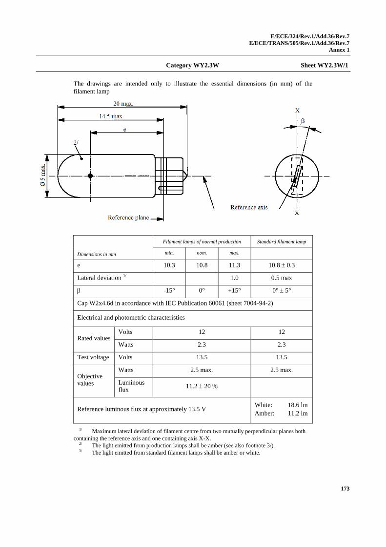
E/ECE/324/Rev.1/Add.36/Rev.7
E/ECE/TRANS/505/Rev.1/Add.36/Rev.7
Annex 1
173
Category WY2.3W Sheet WY2.3W/1
The drawings are intended only to illustrate the essential dimensions (in mm) of the
filament lamp
Dimensions in mm
Filament lamps of normal production Standard filament lamp
min. nom. max.
e 10.3 10.8 11.3 10.8 0.3
Lateral deviation 1/
1.0 0.5 max
-15° 0° +15° 0° 5°
Cap W2x4.6d in accordance with IEC Publication 60061 (sheet 7004-94-2)
Electrical and photometric characteristics
Rated values Volts 12 12
Watts 2.3 2.3
Test voltage Volts 13.5 13.5
Objective values
Watts 2.5 max. 2.5 max.
Luminous flux
11.2 20 %
Reference luminous flux at approximately 13.5 V White: 18.6 lm
Amber: 11.2 lm
1/ Maximum lateral deviation of filament centre from two mutually perpendicular planes both
containing the reference axis and one containing axis X-X. 2/ The light emitted from production lamps shall be amber (see also footnote 3/). 3/ The light emitted from standard filament lamps shall be amber or white.
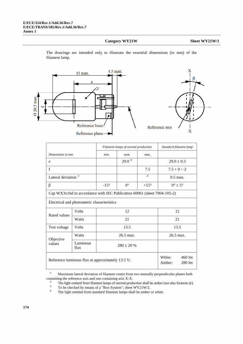
E/ECE/324/Rev.1/Add.36/Rev.7
E/ECE/TRANS/505/Rev.1/Add.36/Rev.7
Annex 1
174
Category WY21W Sheet WY21W/1
The drawings are intended only to illustrate the essential dimensions (in mm) of the
filament lamp.
Dimensions in mm
Filament lamps of normal production Standard filament lamp
min. nom. max.
e 29.0 2/ 29.0 0.3
f 7.5 7.5 + 0 / -2
Lateral deviation 1/
2/
0.5 max.
-15° 0° +15° 0° 5°
Cap WX3x16d in accordance with IEC Publication 60061 (sheet 7004-105-2)
Electrical and photometric characteristics
Rated values Volts 12 12
Watts 21 21
Test voltage Volts 13.5 13.5
Objective values
Watts 26.5 max. 26.5 max.
Luminous flux
280 20 %
Reference luminous flux at approximately 13.5 V: White: 460 lm
Amber: 280 lm
1/ Maximum lateral deviation of filament centre from two mutually perpendicular planes both
containing the reference axis and one containing axis X-X. 2/ The light emitted from filament lamps of normal production shall be amber (see also footnote 4/). 3/ To be checked by means of a "Box-System"; sheet WY21W/2. 4/ The light emitted from standard filament lamps shall be amber or white.
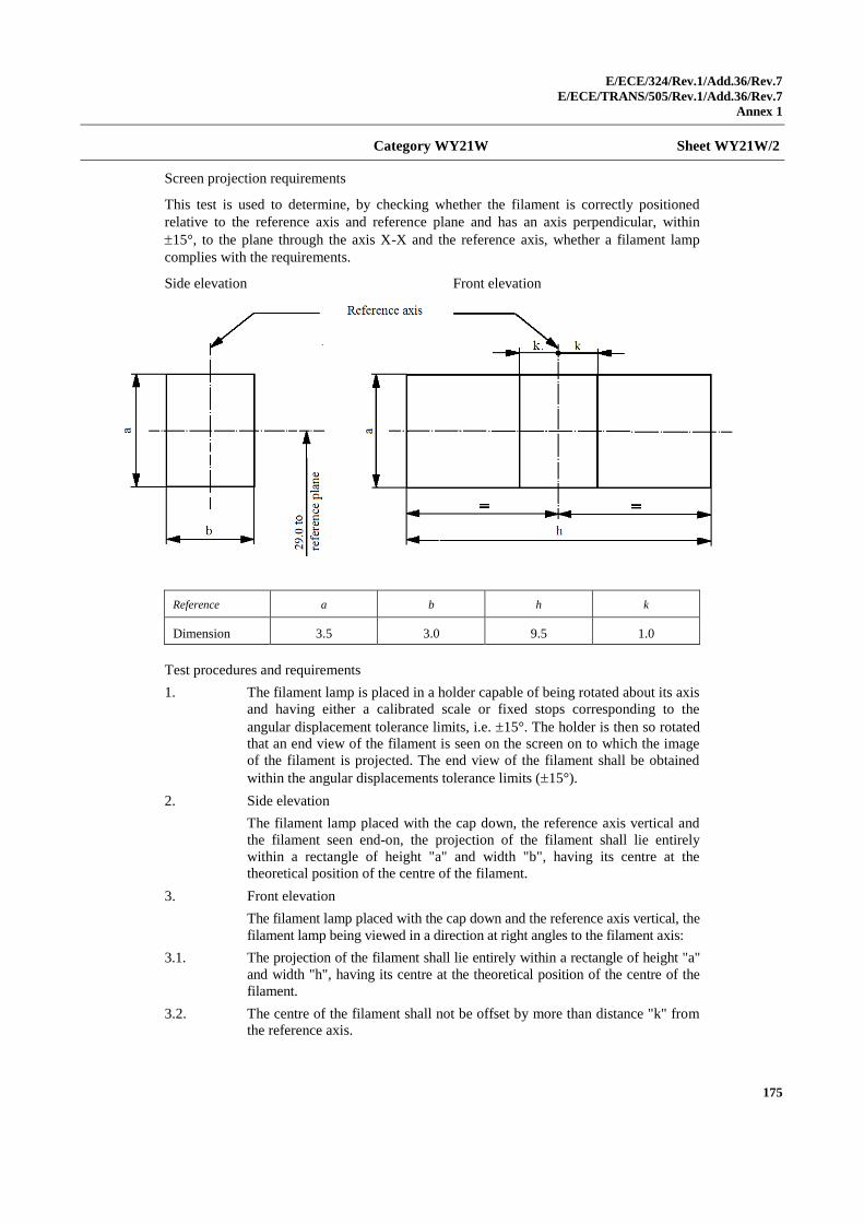
E/ECE/324/Rev.1/Add.36/Rev.7
E/ECE/TRANS/505/Rev.1/Add.36/Rev.7
Annex 1
175
Category WY21W Sheet WY21W/2
Screen projection requirements
This test is used to determine, by checking whether the filament is correctly positioned
relative to the reference axis and reference plane and has an axis perpendicular, within
15°, to the plane through the axis X-X and the reference axis, whether a filament lamp
complies with the requirements.
Side elevation Front elevation
Reference a b h k
Dimension 3.5 3.0 9.5 1.0
Test procedures and requirements
1. The filament lamp is placed in a holder capable of being rotated about its axis
and having either a calibrated scale or fixed stops corresponding to the
angular displacement tolerance limits, i.e. 15°. The holder is then so rotated
that an end view of the filament is seen on the screen on to which the image
of the filament is projected. The end view of the filament shall be obtained
within the angular displacements tolerance limits (15°).
2. Side elevation
The filament lamp placed with the cap down, the reference axis vertical and
the filament seen end-on, the projection of the filament shall lie entirely
within a rectangle of height "a" and width "b", having its centre at the
theoretical position of the centre of the filament.
3. Front elevation
The filament lamp placed with the cap down and the reference axis vertical, the
filament lamp being viewed in a direction at right angles to the filament axis:
3.1. The projection of the filament shall lie entirely within a rectangle of height "a"
and width "h", having its centre at the theoretical position of the centre of the
filament.
3.2. The centre of the filament shall not be offset by more than distance "k" from
the reference axis.
E/ECE/324/Rev.1/Add.36/Rev.7
E/ECE/TRANS/505/Rev.1/Add.36/Rev.7
Annex 2
176
Annex 2
Communication
(Maximum format: A4 (210 x 297 mm))
1
concerning2: Approval granted
Approval extended
Approval refused
Approval withdrawn
Production definitively discontinued
of a type of filament lamp pursuant to Regulation No. 37
Approval No. .................................................... Extension No. ............................................
1. Trade name or mark of the device: ....................................................................
2. Manufacturer's name for the type of device: ......................................................
3. Manufacturer's name and address: .....................................................................
4. If applicable, name and address of manufacturer's representative: ....................
...........................................................................................................................
5. Submitted for approval on: ................................................................................
6. Technical Service responsible for conducting approval tests: ...........................
...........................................................................................................................
7. Date of report issued by that Service: ................................................................
8. Number of report issued by that Service: ..........................................................
9. Concise description:...........................................................................................
Category of filament lamp: ................................................................................
Rated voltage: ....................................................................................................
1 Distinguishing number of the country which has granted/extended/refused/withdrawn approval (see
approval provisions in the Regulation).
2 Strike out what does not apply.
issued by: Name of administration
......................................
....................…………..
....................………….. 1
E/ECE/324/Rev.1/Add.36/Rev.7
E/ECE/TRANS/505/Rev.1/Add.36/Rev.7
Annex 2
177
Rated wattage: ...................................................................................................
Colour of the light emitted: White/selective-yellow/amber/red2
Colour coating on glass bulb: yes/no2
Halogen filament lamp: yes/no2
10. Position of the approval mark: ...........................................................................
11. Reason(s) for extension (if applicable): .............................................................
12. Approval granted/refused/extended/withdrawn2:
13. Place: .................................................................................................................
14. Date: ..................................................................................................................
15. Signature: ...........................................................................................................
16. The following documents, bearing the approval mark shown above, are
available on request: ..........................................................................................
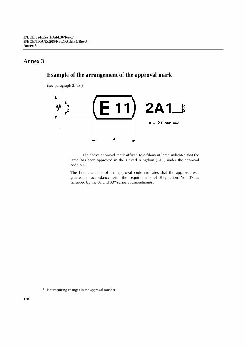
E/ECE/324/Rev.1/Add.36/Rev.7
E/ECE/TRANS/505/Rev.1/Add.36/Rev.7
Annex 3
178
Annex 3
Example of the arrangement of the approval mark
(see paragraph 2.4.3.)
The above approval mark affixed to a filament lamp indicates that the
lamp has been approved in the United Kingdom (E11) under the approval
code A1.
The first character of the approval code indicates that the approval was
granted in accordance with the requirements of Regulation No. 37 as
amended by the 02 and 03* series of amendments.
* Not requiring changes in the approval number.
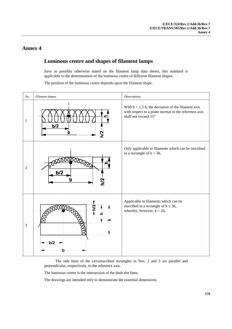
E/ECE/324/Rev.1/Add.36/Rev.7
E/ECE/TRANS/505/Rev.1/Add.36/Rev.7
Annex 4
179
Annex 4
Luminous centre and shapes of filament lamps
Save as possibly otherwise stated on the filament lamp data sheets, this standard is
applicable to the determination of the luminous centre of different filament shapes.
The position of the luminous centre depends upon the filament shape.
No. Filament shapes Observations
1
With b > 1.5 h, the deviation of the filament axis
with respect to a plane normal to the reference axis
shall not exceed 15°
2
Only applicable to filaments which can be inscribed
in a rectangle of b > 3h.
3
b
b/2
k
h
h/3
Applicable to filaments which can be
inscribed in a rectangle of b 3h,
whereby, however, k < 2h.
The side lines of the circumscribed rectangles in Nos. 2 and 3 are parallel and
perpendicular, respectively, to the reference axis.
The luminous centre is the intersection of the dash-dot lines.
The drawings are intended only to demonstrate the essential dimensions.
E/ECE/324/Rev.1/Add.36/Rev.7
E/ECE/TRANS/505/Rev.1/Add.36/Rev.7
Annex 5
180
Annex 5
Checking the colour of filament lamps
1. General
1.1. Measurements shall be made on finished lamps. Filament lamps with
secondary (outer) bulb acting as colour filter shall be handled as filament
lamp with primary bulb.
1.2. Tests shall be made at an ambient temperature of 23 °C ± 5 °C.
1.3. Tests shall be made at test voltage(s) as specified in the relevant lamp data
sheet.
1.4. Filament lamps shall be measured preferably in the normal operating
position. In case of dual filament lamps the high wattage (major or driving
beam) filament shall be operated only.
1.5. Before starting a test, the stabilisation of the temperature of the filament lamp
shall be obtained by operating at test voltage for 10 minutes. In the case of
filament lamps, for which more than one test voltage is specified, the relevant
test voltage value shall be used for achieving stabilization.
2. Colour
2.1. Colour tests shall be made with a measuring system that determines CIE
trichromatic co-ordinates of the received light with an accuracy of ±0.002.
2.2. The trichromatic coordinates shall be measured with a colourimetric receiver
integrating over a right circular cone subtending an angle of minimum 5° and
maximum 15°, at the centre of the filament.
2.3. Measuring directions (see the figure below).
2.3.1. Initially, the receiver shall be positioned perpendicular to the lamp axis and to
the filament axis (or plane in case of a curved filament). After measurement
the receiver shall be moved around the filament lamp in bi-directional steps
of about 30° until the area specified in paragraphs 2.3.2. or 2.3.3. is covered.
In each position a measurement shall be made. However, no measurement
shall be made when:
(a) The centreline of the receiver coincides with the filament axis; or
(b) The line of sight between the receiver and the filament is blocked by
opaque (non-transmitting) parts of the light source, such as lead wires
or a second filament, if any.
2.3.2. For filament lamps used in headlamps, measurements shall be made in
directions around the filament lamp with the centreline of the receiver
aperture located within an angle ±30°, from the plane perpendicular to the
lamp axis with the origin in the centre of the filament. In case of filament
lamps with two filaments, the centre of the driving beam filament shall be
taken.
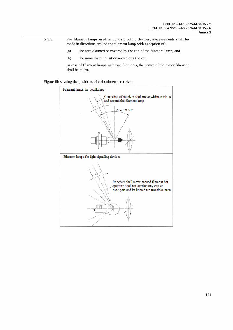
E/ECE/324/Rev.1/Add.36/Rev.7
E/ECE/TRANS/505/Rev.1/Add.36/Rev.6
Annex 5
181
2.3.3. For filament lamps used in light signalling devices, measurements shall be
made in directions around the filament lamp with exception of:
(a) The area claimed or covered by the cap of the filament lamp; and
(b) The immediate transition area along the cap.
In case of filament lamps with two filaments, the centre of the major filament
shall be taken.
Figure illustrating the positions of colourimetric receiver
E/ECE/324/Rev.1/Add.36/Rev.7
E/ECE/TRANS/505/Rev.1/Add.36/Rev.7
Annex 6
182
Annex 6
Minimum requirements for quality control procedures by the manufacturer
1. General
The conformity requirements shall be considered satisfied from a
photometric, geometrical, visual and electrical standpoint if the specified
tolerances for production filament lamps in the relevant data sheet of
Annex 1 and the relevant data sheet for the caps are met.
2. Minimum requirements for verification of conformity by the manufacturer
For each type of filament lamp the manufacturer or the holder of the approval
mark shall carry out tests, in accordance with the provisions of this
Regulation, at appropriate intervals.
2.1. Nature of tests
Tests of conformity of these specifications shall cover their photometric,
geometrical and optical characteristics.
2.2. Methods used in tests
2.2.1. Tests shall generally be carried out in accordance with the methods set out in
this Regulation.
2.2.2. The application of paragraph 2.2.1. requires regular calibration of test
apparatus and its correlation with measurements made by a competent
authority.
2.3. Nature of sampling
Samples of filament lamps shall be selected at random from the production of
a uniform batch. A uniform batch means a set of filament lamps of the same
type, defined according to the production methods of the manufacturer.
2.4. Inspected and recorded characteristics
The filament lamps shall be inspected and test results recorded following the
grouping of characteristics as listed in Annex 7, Table 1.
2.5. Criteria governing acceptability
The manufacturer or the holder of approval is responsible for carrying out a
statistical study of the test results in order to meet the specifications laid
down for verification of conformity of production in paragraph 4.1. of this
Regulation.
Compliance shall be assured if the level of acceptable non-compliance per
grouping of characteristics given in Table 1 of Annex 7 is not exceeded. This
means that the number of filament lamps not complying with the requirement
for any grouping of characteristics of any filament lamp type does not exceed
the qualifying limits in the relevant Tables 2, 3 or 4 of Annex 7.
Note: Each individual filament lamp requirement shall be considered as a
characteristic.
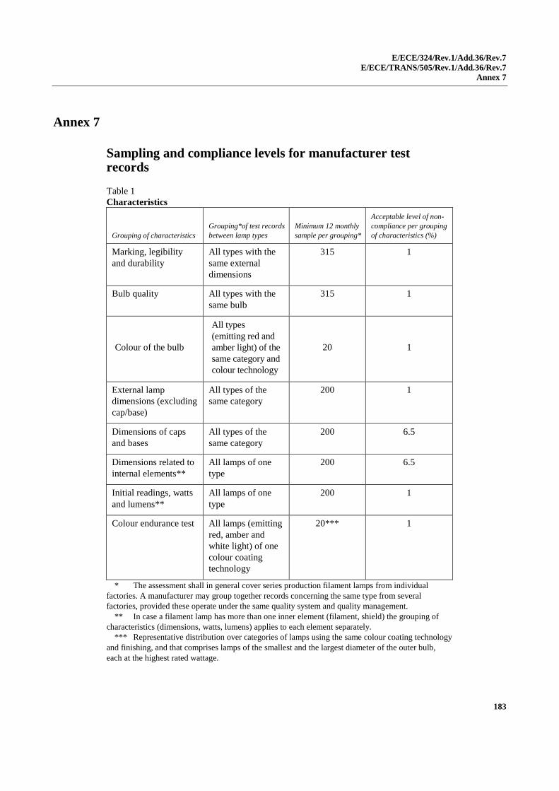
E/ECE/324/Rev.1/Add.36/Rev.7
E/ECE/TRANS/505/Rev.1/Add.36/Rev.7
Annex 7
183
Annex 7
Sampling and compliance levels for manufacturer test records
Table 1
Characteristics
Grouping of characteristics
Grouping*of test records
between lamp types
Minimum 12 monthly
sample per grouping*
Acceptable level of non-
compliance per grouping
of characteristics (%)
Marking, legibility
and durability
All types with the
same external
dimensions
315 1
Bulb quality All types with the
same bulb
315 1
Colour of the bulb
All types
(emitting red and
amber light) of the
same category and
colour technology
20 1
External lamp
dimensions (excluding
cap/base)
All types of the
same category
200 1
Dimensions of caps
and bases
All types of the
same category
200 6.5
Dimensions related to
internal elements**
All lamps of one
type
200 6.5
Initial readings, watts
and lumens**
All lamps of one
type
200 1
Colour endurance test All lamps (emitting
red, amber and
white light) of one
colour coating
technology
20*** 1
* The assessment shall in general cover series production filament lamps from individual
factories. A manufacturer may group together records concerning the same type from several
factories, provided these operate under the same quality system and quality management.
** In case a filament lamp has more than one inner element (filament, shield) the grouping of
characteristics (dimensions, watts, lumens) applies to each element separately.
*** Representative distribution over categories of lamps using the same colour coating technology
and finishing, and that comprises lamps of the smallest and the largest diameter of the outer bulb,
each at the highest rated wattage.
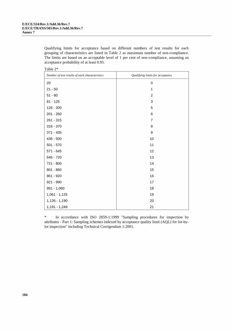
E/ECE/324/Rev.1/Add.36/Rev.7
E/ECE/TRANS/505/Rev.1/Add.36/Rev.7
Annex 7
184
Qualifying limits for acceptance based on different numbers of test results for each
grouping of characteristics are listed in Table 2 as maximum number of non-compliance.
The limits are based on an acceptable level of 1 per cent of non-compliance, assuming an
acceptance probability of at least 0.95.
Table 2*
Number of test results of each characteristics Qualifying limits for acceptance
20
21 - 50
51 - 80
81 - 125
126 - 200
201 - 260
261 - 315
316 - 370
371 - 435
436 - 500
501 - 570
571 - 645
646 - 720
721 - 800
801 - 860
861 - 920
921 - 990
991 - 1,060
1,061 - 1,125
1,126 - 1,190
1,191 - 1,249
0
1
2
3
5
6
7
8
9
10
11
12
13
14
15
16
17
18
19
20
21
* In accordance with ISO 2859-1:1999 "Sampling procedures for inspection by
attributes - Part 1: Sampling schemes indexed by acceptance quality limit (AQL) for lot-by-
lot inspection" including Technical Corrigendum 1:2001.
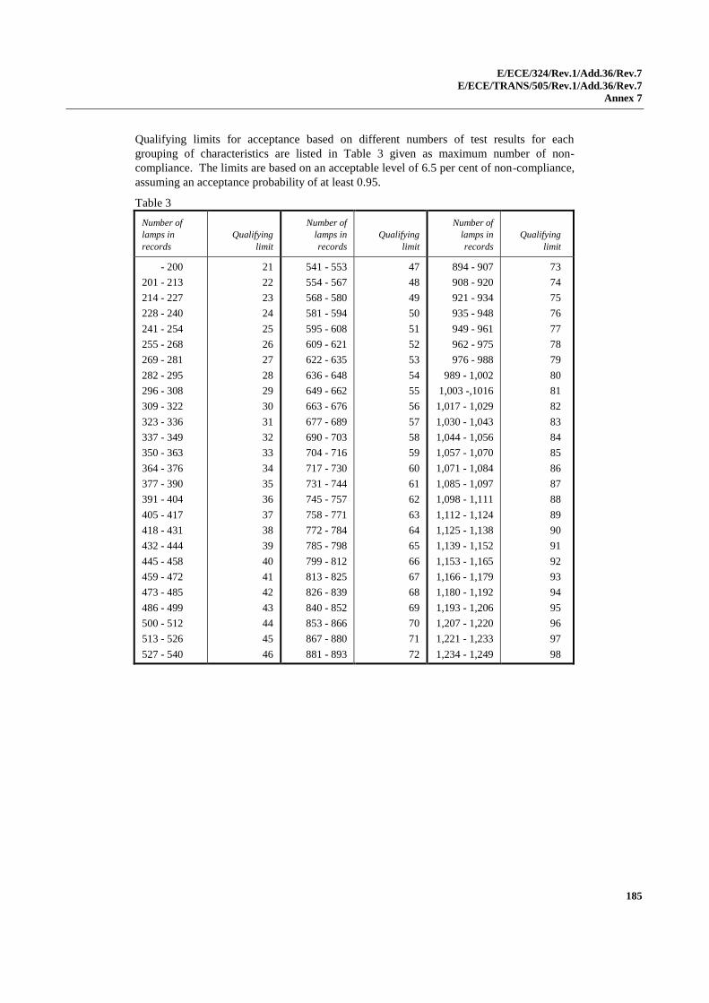
E/ECE/324/Rev.1/Add.36/Rev.7
E/ECE/TRANS/505/Rev.1/Add.36/Rev.7
Annex 7
185
Qualifying limits for acceptance based on different numbers of test results for each
grouping of characteristics are listed in Table 3 given as maximum number of non-
compliance. The limits are based on an acceptable level of 6.5 per cent of non-compliance,
assuming an acceptance probability of at least 0.95.
Table 3
Number of
lamps in
records
Qualifying
limit
Number of
lamps in
records
Qualifying
limit
Number of
lamps in
records
Qualifying
limit
- 200
201 - 213
214 - 227
228 - 240
241 - 254
255 - 268
269 - 281
282 - 295
296 - 308
309 - 322
323 - 336
337 - 349
350 - 363
364 - 376
377 - 390
391 - 404
405 - 417
418 - 431
432 - 444
445 - 458
459 - 472
473 - 485
486 - 499
500 - 512
513 - 526
527 - 540
21
22
23
24
25
26
27
28
29
30
31
32
33
34
35
36
37
38
39
40
41
42
43
44
45
46
541 - 553
554 - 567
568 - 580
581 - 594
595 - 608
609 - 621
622 - 635
636 - 648
649 - 662
663 - 676
677 - 689
690 - 703
704 - 716
717 - 730
731 - 744
745 - 757
758 - 771
772 - 784
785 - 798
799 - 812
813 - 825
826 - 839
840 - 852
853 - 866
867 - 880
881 - 893
47
48
49
50
51
52
53
54
55
56
57
58
59
60
61
62
63
64
65
66
67
68
69
70
71
72
894 - 907
908 - 920
921 - 934
935 - 948
949 - 961
962 - 975
976 - 988
989 - 1,002
1,003 -,1016
1,017 - 1,029
1,030 - 1,043
1,044 - 1,056
1,057 - 1,070
1,071 - 1,084
1,085 - 1,097
1,098 - 1,111
1,112 - 1,124
1,125 - 1,138
1,139 - 1,152
1,153 - 1,165
1,166 - 1,179
1,180 - 1,192
1,193 - 1,206
1,207 - 1,220
1,221 - 1,233
1,234 - 1,249
73
74
75
76
77
78
79
80
81
82
83
84
85
86
87
88
89
90
91
92
93
94
95
96
97
98
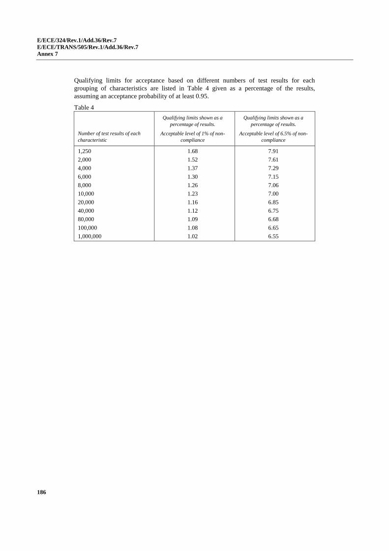
E/ECE/324/Rev.1/Add.36/Rev.7
E/ECE/TRANS/505/Rev.1/Add.36/Rev.7
Annex 7
186
Qualifying limits for acceptance based on different numbers of test results for each
grouping of characteristics are listed in Table 4 given as a percentage of the results,
assuming an acceptance probability of at least 0.95.
Table 4
Number of test results of each
characteristic
Qualifying limits shown as a
percentage of results.
Acceptable level of 1% of non-
compliance
Qualifying limits shown as a
percentage of results.
Acceptable level of 6.5% of non-
compliance
1,250
2,000
4,000
6,000
8,000
10,000
20,000
40,000
80,000
100,000
1,000,000
1.68
1.52
1.37
1.30
1.26
1.23
1.16
1.12
1.09
1.08
1.02
7.91
7.61
7.29
7.15
7.06
7.00
6.85
6.75
6.68
6.65
6.55
E/ECE/324/Rev.1/Add.36/Rev.7
E/ECE/TRANS/505/Rev.1/Add.36/Rev.7
Annex 8
187
Annex 8
Minimum requirements for spot checks by the Type Approval Authority
1. General
The conformity requirements shall be considered satisfied from a
photometric, geometrical, visual and electrical standpoint if the specified
tolerances for production filament lamps in the relevant data sheet of
Annex 1 and the relevant data sheet for the caps are met.
2. The conformity of mass-produced filament lamps shall not be contested if the
results are in agreement with Annex 9 to this Regulation.
3. Conformity shall be contested and the manufacturer requested to make the
production meet the requirements if the results are not in agreement with
Annex 9 to this Regulation.
4. If paragraph 3 of this annex is applied, a further sample of 250 filament
lamps, selected at random from a recent production run, shall be taken within
two months.
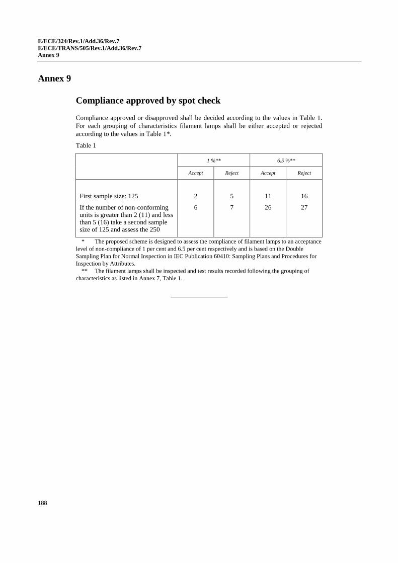
E/ECE/324/Rev.1/Add.36/Rev.7
E/ECE/TRANS/505/Rev.1/Add.36/Rev.7
Annex 9
188
Annex 9
Compliance approved by spot check
Compliance approved or disapproved shall be decided according to the values in Table 1.
For each grouping of characteristics filament lamps shall be either accepted or rejected
according to the values in Table 1*.
Table 1
1 %** 6.5 %**
Accept Reject Accept Reject
First sample size: 125
If the number of non-conforming units is greater than 2 (11) and less than 5 (16) take a second sample size of 125 and assess the 250
2
6
5
7
11
26
16
27
* The proposed scheme is designed to assess the compliance of filament lamps to an acceptance
level of non-compliance of 1 per cent and 6.5 per cent respectively and is based on the Double
Sampling Plan for Normal Inspection in IEC Publication 60410: Sampling Plans and Procedures for
Inspection by Attributes.
** The filament lamps shall be inspected and test results recorded following the grouping of
characteristics as listed in Annex 7, Table 1.