Embed Size (px)
Citation preview
AGN 165 ISSUE B/1/14
Application Guidance Notes: Technical Information from Cummins Generator Technologies
AGN 165 – Parallel Operation with Mains Grid Systems
AvK AND STAMFORD ALTERNATOR SUITABILITY Standard industrial AvK and STAMFORD alternators may not be suitable for operating in
parallel with a mains grid system network. There is a range of AvK and STAMFORD alternators
that are designed specifically for ‘grid connection’. These specially designed alternators are
manufactured with many special technical features that include:
Perfect lap windings.
Enhanced electrical insulation system (EIS).
Winding out-hang bracing.
All alternator winding designs are suitable for ‘grid connection’. The alternator, designed
primarily for close coupling to a RIC diesel or gas prime mover, will be offered at a rating
suitable for the grid/network, to comply with any existing Grid Codes, for the following technical
reasons:
To ensure the EIS dielectric strength is maintained as high as possible by controlling
the operating temperature of the EIS.
To ensure peak operating efficiency.
To provide a capability to cope with operation over a wide voltage, frequency and
power factor range.
AvK and STAMFORD alternators are nominated for Static Grid Code requirements by
considering design parameters to ensure the operating rotor load angle is controlled to provide
the best possible capability to cope with voltage sags and swells, which are acceptable if within
AGN 165 ISSUE B/2/14
+/- 5% step change over 20mS period, where the alternator will momentarily be subjected to
100% overload current transient.
But, for a +/- 10% voltage change, the requirement is that this must be over a 4 second period,
thereby having a dV/dt gradient which does not subject the alternator to multiples of rated
current.
Experience shows that, Rate-of-Change-of-Frequency (RoCoF) and Vector Shift protection
equipment are not fast enough to protect a Generating Set from damage under step network
changes; it is an unfortunate fact that the damage to the alternator components has been
imposed before either of these protection modules have even initiated a command to the
Circuit Breaker (CB) to disconnect.
The selection of the alternator is typically based on the alternator’s synchronous reactance
(Xd) <2.2pu....where the SCR = 0.5. This is to ensure stable operations with Grid Code
regulations.
GRID CODES When considering applying a Generating Set to a grid/network connect application (embedded
generator) it is most important that the expected duty of that Generating Set and the
operational characteristics of the grid at the proposed point of common coupling (PCC) are
fully understood.
The operator of the grid/network, whether that be at distribution level (Distribution Network
Operator – DNO) or transmission level (TNO), is very likely to have a technical specification,
which describes the variances of the voltage and frequency at the proposed PCC. This
specification document is often referred to as the Grid Code, and each DNO / TNO will have a
Grid Code specification that is unique to their local operating conditions, but with several
aspects that are now becoming a familiar requirement common to certain network operating
organisations.
These grid codes will specify the operational bandwidths for network voltage levels, frequency
levels, along with local requirements for operational power factor, with the proposed
Generating Set equipment package being required to operate within the specified envelope at
the contractually agreed rated power level. Typically, these requirements are being specified
at +/-10% Voltage, +/-5% Frequency and 0.8 pf lag through to 0.9 pf lead.
Such fundamental requirements are often described as the network’s ‘Static’ requirements, as
they describe the outer limits of the x, y & z axis of the three dimensional envelope. Whilst this
is a starting point to consider alternator nomination, the real detail is in identifying the actual
rate-of-change (slew rate) of each of these three fundamental characteristics, which will occur
within the host electrical network’s system.
The consequence of any change is to force the connected Generating Set to realign with the
new prevailing conditions. The rate of change and the degree of change become significant
factors, which must be identified, as this complex behaviour will impose operational stress to
electrical and mechanical components incorporated within the embedded power generation
AGN 165 ISSUE B/3/14
equipment package. This magnitude of imposed stress being related to the rate of change of
the host network, where the factor associated with magnitude is amplified beyond a directly
proportional relationship.
Simply put; will the synchronized Generating Set 'ride-through' the system disturbance without:
losing synchronism
pole-slipping
Importing MVAr. The objective answer must be maybe and should be yes. Yes, if the system impedance between the point of 'abnormal occurrence' and the terminals of the alternator is high enough to ensure that the level and rate of voltage deviation does not result in the Generating Set’s synchronism-retaining-torque being exceeded. The subjective answer is based on the considerations set out below. Establishing the operating condition of the alternator and engine prior to the 'abnormal occurrence', then identifying the system impedance between the 'abnormal occurrence' and the alternator’s terminals. Then considering the Generating Set’s behaviour with regard to dynamics of the alternator’s excitation system and the engine’s behavior in terms rate of change of shaft power capability and conclude with the likelihood of:
losing synchronism
pole-slipping
Importing MVAr
CONSIDERATIONS REQUIRED WHEN APPLYING ALTERNATORS TO GRID CONNECTED APPLICATIONS
It is accepted that at the quotation stage of any project, access to real operational data will not
be available. Nevertheless, technical discussions based on salient points from the customer’s
specification should be encouraged. Internet access to satellite based views of the proposed
site can provide an insight into the adjacency of other power generation plant, the runs of
overhead lines, etc. It is imperative that, at the earliest opportunity, power system analysis
equipment is fitted to the PCC to monitor the local network’s characteristics. This equipment
should remain in place for least the first six months of operation over which period a log should
be created in which plant activities and installed electrical protection device trips and alarms
are included.
There follows a list of top level aspects that must be introduced into the decision making
process for equipment selection at the earliest possible opportunity:
Identification of the operator of the host network.
The relevant Codes or Standards that will be applied for performance of the embedded
power generation equipment.
Ask questions about typical operating characteristics at that PCC for system:
AGN 165 ISSUE B/4/14
Nominal voltage and typical variance in terms of +/- V%
Nominal frequency and typical variance in terms of +/- Hz%
If there is a specified expectation of fault ride through, and thereby a contractual
requirement to contribute to grid fault clearance situations or network support during
momentary grid overload conditions, which have forced the network voltage or
frequency to levels outside the static grid code requirements, then some form of
mitigation to protect against damaging the asset must be initiated.
Gain an understanding of the power flow and fault level at the proposed PCC. This
work is best undertaken in conjunction with reference to a Single Line Diagram (SLD)
that provides good information regarding details of local transformers, the identification
of local consumers and any local power generation plant. Also, with regard to
consumers, some understanding of the characteristics of their loads in terms of impact
load steps, along with harmonically distorting Non-Linear Loads.
Understand the local distribution electrical network in terms of local feeder conductors.
For example, if overhead lines are being used and the local area has a weather related
history that suggests there is a risk of lightning strikes, then request details to be
provided regarding the locally installed transient voltage surge suppression / arrestor
equipment.
If, for example, the PCC is at 11kV and the SLD shows that the local 11kV network is
directly supporting local loads at high power levels, then their demand on that 11kV
network could introduce levels of disturbance, which it would be imprudent to subject
directly to the alternator’s terminals. Establish if the 11kV system includes vacuum or
SF6 type circuit breakers, both are known to be stress raisers for wound components.
Such observations should be used to introduce considerations of operating the
Generating Sets at LV, with an interconnecting transformer between the LV Generating
Sets and the HV grid network. This transformer will provide a degree of isolation and
so ‘soft coupling’ which will reduce the degree of stress imposed on the Generating Set
equipment package components.
Specified operating conditions:
o Continuous duty
o Peak Lopping
o Constant kW at a specified pf
o Dynamic power contribution provided by appropriate speed control
With regard to the expected mode of operation, there is always a risk that each time a
Generating Set is synchronised there is a risk of a ‘rough’ synchronisation and so needs
the introduction of a failure mechanism. For this reason, Cummins Generator
Technologies expect every synchronising exercise to be conducted by suitably set
auto-synchronising equipment, which will ensure that the current transient will never
exceed 50% of the Generating Set’s rated current level.
AGN 165 ISSUE B/5/14
If peak lopping, then the associated frequency with which the Generating Sets will be
synchronised, increases the risks of unseen damage taking place. Establish how many
times per day, times per week, the Generating Sets will be synchronised to the local
grid.
When Generating Sets are operated in parallel with a grid, the fact that operational
voltage and frequency levels will not be fixed with these variations being imposed on
the alternators, which is contracted to deliver constant power, need to be considered
in terms of the extra losses – and so increased heating effect - certain combinations of
the variables will have on the alternator component operating temperatures. This is but
one of the reasons why it is a contractual requirement by Cummins Generator
Technologies that LV alternators will not be operated above their published Class ’F’
(105/40) temperature rise ratings.
For MV and HV Generating Sets, please discuss this thermal rating issue with the
factory to ensure Cummins Generator Technologies will support all warranty
expectations for the alternator.
When considering operating temperatures of the Generating Set equipment package,
care must be taken to ensure that the allocated space for the proposed power
generation packages to be installed in an engineered manner, permits adequate
cooling, ventilation and clean air circulation; provided in order to ensure a microclimate
is not created.
Are the proposed site conditions likely to pose environmental challenges in terms of
local ambient temperatures, solar radiation, dusty and so contaminated cooling air,
prevailing wind direction, salt laden atmosphere? Remember that sand has a high
saline content. Is the installation at an altitude exceeding 1000m above sea level? If
any of these conditions apply, then mitigating engineered solutions must form part of
the planned equipment package and design control of the site layout.
The operator of the host grid/network will require assurance that the proposed
generation equipment will not promote instability of the local grid/network. Typically, a
modelling study of the generation equipment is undertaken by the operator of the
network, and this process requires the supplier of the generation equipment to
complete the necessary Application to Connect document. This document will require
the collation of many different parameters for individually both engine and alternator
and then for the two operating as a Generating Set. Do not underestimate the
complexity of the questions and therefore, the incurred cost of providing the necessary
data. Often the proposer needs to engage a consultant.
Identify who will have the responsibility for installation and commissioning and then the
degree of complexity required for this most important stage of the process. It is most
important that due consideration is given to ensure compliance with the grid operator,
local authority environmental laws and local citizen protection.

AGN 165 ISSUE B/6/14
The whole aspect of providing a co-ordinated electrical protection scheme is very
specialist to the local site. Often the proposer needs to engage a consultant.
Scope of Work for a typical Site Survey
There follows, a list of actions in information gathering to permit adequate consideration for
connecting a Generating Set to a grid/network:
1. The specifying network operator to be contracted by the commercial team, to identify if
they are buying:
a. Power generation equipment packages.
b. kW & kVAr.
This will lead to identification of the business partners and this will be the start of
identifying, and so gaining, an understanding of that partner’s capability.
2. Identification of the site(s) location.
This can initiate a web based satellite photo survey, looking for overhead cable
lines and other power generation stations and nearby environmental hazards.
3. Site survey(s).
Details of our business partner’s first walk of the site and survey of how the Point
of Common Coupling (PCC) will be configured.
4. Acquisition of the local network's Single Line Drawings (SLD).
These are only likely to be provided to the network’s selected bidder and so
selected partner for the proposed project.
5. Technical work to establish the network’s Power Flows and local system stability.
If Cummins Generator Technologies work with a competent partner, then this
system study will be part of their action plan. Cummins Generator Technologies
are not the experts in this type of work, so can contribute but not lead. If there is a
need to lead, then all parties must engage the services of a specialist company
(TNEI Manchester for example).
6. Modelling of the network with and without the new embedded equipment operating.
Same comments as item 5, above.
7. Providing alternator modelling data for items 5 and 6, above.
This would, typically, be 3 man-days for a Customer Engineering Service (CES)
engineer, for each type of alternator / site location.
Site visits by CES personnel during the final stages of site installation - deployment
of site monitoring power system analysing equipment, such as the Dranetz PX5 or
similar.
AGN 165 ISSUE B/7/14
8. Site visits by CES personnel during the commissioning stage.
9. Site and customer visits to tailor the 'care' regime and data gathering policy.
10. Site presence of CES experienced technical person during infantile period of operation.
This should include the training of the designated CES representative for site data
gathering and site operational activities.
11. Site presence of designated CES representative for the duration of the warranty period.
12. The CES representative to accept the returned Dranetz data, plus details of the network
characteristics, based on local information gained from the local Network (DNO or
TNO) control room - which the business partner should be gathering to understand the
risk of his asset.
Note: There may well be a process for the business partners, regarding the handing-over of
the power generation equipment to their customer; this phase may introduce complex
difficulties regarding Cummins Generator Technologies being allowed to remain on site. This
may require the Contractual negotiation.
Conclusion
Application Engineering are able to assist with the considerations that are necessary to comply with the expectations contained within the numerous Grid Codes. To date there is no clear route forward for claiming 'absolute' compliance. There are many aspects of embedded operation that have been identified as challenging. Each challenging situation needs subjective consideration of what level of detection/protection has been considered and will be incorporated in the complete Generating Set equipment package. The major concern is when the Grid to which the embedded Generating Set is paralleled experiences a 'disturbance'. The magnitude of this disturbance is likely to cause the Generating Set to lose synchronism and then it is important to consider how the consequential behavior and stress imposed on the equipment package can be minimized. GRID CONNECTED GENERATING SETS OPERATING AT A LEADING POWER FACTOR
National Grid Codes are becoming more demanding, with many now having a specified
expectation for the Generating Set to operate with a leading power factor (pf). Confirming the
capability of an alternator to operate with a leading pf introduces a number of complex
considerations, where both the grid network and the Generating Set equipment package must
be reviewed to ensure overall operational compatibility can be assured.
The need for a Generating Set to operate with a leading pf is usually only stipulated when the
host grid is weak and therefore, suffers from an inherently wide bandwidth variation of the
system operating voltage level. Under low loading levels the grid voltage level will rise and this
is when alternator may be called upon to reduce its excitation level – possibly entering a
leading pf mode of operation - but thereby, allowing the grid voltage level to reduce for the
benefit of the remaining connected load.
AGN 165 ISSUE B/8/14
Operating an alternator with a leading pf - therefore a low excitation level - makes that
alternator more susceptible to losing synchronous operation with the grid network – a situation
called ‘pole slipping’ – and such an event will be stressful to the Generating Set concerned
and may also promote system instability for the host grid network.
Top Level Recommendations
Leading pf operation requires consideration of the host grid’s stability and operational voltage
bandwidth. Therefore, gaining technical knowledge of how the grid operator presently achieves
this is imperative. The resulting technical considerations may promote the nomination of
specialist equipment to be incorporated as part of the ‘new package’, and here dynamic voltage
regulation in terms of a synchronous condenser may be deliberated.
A system modelling study should always be conducted. The resulting data will assist with
protection parameter settings and risk mitigation.
The nominated alternator should have a synchronous reactance (Xd) no higher than 2.2pu
under the condition of the lowest level of steady state system voltage.
The protection package must include all items listed 1 to 8, as detailed in Section 3 further on
in this AGN.
The settings of the protection parameters should be based on:
The risks identified during the modelling study.
Historically established levels based on International engineering documents such as
G59 and G75.
The following sections outline the considerations that form the basis of the top level
recommendations.
Technical Considerations
Section 1.0. Power Generation Equipment
Consideration needs to be given to the characteristics of the proposed equipment package.
This should begin by considering the specified performance requirements and therefore an
indication of mode of operation in terms of fixed/variable kW, and correspondingly
fixed/variable kVAr.
Section 1.1. Prime Mover
The characteristics of an RIC engine fuelled by Gas – further compounded by the type of gas
– compared with a Diesel are very different. Their respective transient behaviour varies greatly
and therefore requires the project engineer to fully consider rotating mass inertia, control
system functions and time constants, thereby resulting equipment package behaviour when
AGN 165 ISSUE B/9/14
the proposed unit is synchronised to a grid network prone to suffering from system
disturbances.
Section 1.2. Alternator Capability Diagram (Operating Chart)
As the construction of these documents is based on the alternator’s synchronous reactance
values, it follows that specifying a value of Xd for the proposed alternator will result in an
inherent capability to cope with leading pf operational duty. This key alternator boundary will
be discussed later within this document.
Section 1.3. Alternator Thermal Rating
The site rating of the alternator must never exceed the Class F thermal rating. This is to ensure
the winding insulation systems retain the highest possible level of dielectric strength to cope
with the imposed dielectric stresses from grid system disturbances. See also Section 1.4.
Section 1.4. Alternator Voltage Range
The upper and lower limits of the proposed Point of Common Coupling (PPC) need to be
identified and this bandwidth duly considered against points 1.3 and 2.0.
Section 2.0. Grid System
When an embedded power generation scheme is being planned it is most important for the
Generating Set equipment supplier to conduct a local study of the grid system’s behaviour in
terms of:
Voltage range +/-%
Fault Current levels at the proposed Point of Common Coupling (PCC)
History of local supply system stability and present level of power supply quality
This information must then be duly considered by the project engineer. It is expected that the
project engineer will then conduct a power flow study of the existing installation, and then
propose revisions to the local network. All gathered data should be used to conduct a system
modelling study to identify the likely behaviour of the grid when the proposed embedded
generation scheme is operational.
This modelling exercise will provide the crucial data required for appropriate setting of the
electrical protection system associated with the embedded Generating Set(s).
Section 2.1. Operational Voltage Range
The greater the operational voltage bandwidth, the greater the risk that the alternator will be
operating at a dangerously low excitation level and a pole slip will occur.
AGN 165 ISSUE B/10/14
Section 2.2. System Stability
The mains grid system’s ability to maintain ‘system stability’ can be compromised when
embedded power generation is operating. Stability may be seriously at risk when the
embedded Generating Set is operating in a leading power factor condition.
Section 2.3. Critical Clearing Time (CCT)
CCT is the maximum time between initiation and isolation of a fault on a power system such
that the power system remains transiently stable. This time should be lower than the operation
of the back-up protection.
Operating embedded generation under a condition of leading power factor softens the
Generating Set’s contribution to a fault condition, when compared with a more typical higher
excitation condition under the more typical slightly lagging power factor mode of operation.
The inherent change to the CCT should be considered by the responsible project engineer and
appropriate protection philosophy must be incorporated within the overall electrical protection
scheme.
Section 3.0. Electrical Protection
Many Grid Codes will include specified parameters to be included in the embedded Generating
Set’s electrical protection scheme, and when this is the case bespoke protection packages
must be created and co-ordinated.
The responsible person for the embedded power generation equipment needs to provide
protection to safeguard the embedded Generating Set as an ‘asset’, and shield the host grid
network from stress, should the Generating Set malfunction, whilst ensuring the grid codes
‘ride-through’ requirements are satisfied.
The on-site co-ordinated settings for the protection parameters should be based on system
data calculations. This may be achieved by an experienced engineer conducting power flow
calculations, and/or the result of a computed modelling study of the system.
Section 3.1. Control System
It has been assumed that the Generating Set will be fitted with an Auto-Synchronising package,
and engine and alternator control functions, to ensure controlled contribution of kWe and kVAr.
Comments regarding the functionality of the automatic control elements are not covered within
this document. However; if the control functions allow for manual intervention, then it is
expected that the Generating Set designer will limit the allowable adjustment given to the
manual control function, and these will be ‘locked’ during commissioning.
AGN 165 ISSUE B/11/14
Section 3.2. Protection Parameters
The following list identifies typically specified protection parameters for embedded Generating
Sets:
1. Over/Under Voltage
2. Over/Under Hz
3. Over Current
4. Loss of Mains
4.1 Monitoring all 3 and each individual phase
4.2 Neutral Voltage Displacement
5. Vector Surge
5.1 Vector Shift
5.2 ROCOF
5.3 Phase Angle Displacement
6. Reverse Power (P)
7. Reverse kVAr (Q)
7.1 Loss of Excitation
When operating in parallel with a grid network, which requires the alternator to operate in a
leading power factor mode, extra/revised protection parameters must be considered:
8. Pole Slip Detection
8.1 Rotor Load Angle Detector
8.2 Impedance
8.3 Equal area
Revised settings for all above parameters 1 to 7, when operating in leading power factor mode,
must be considered and introduced to ensure overall system stability is not at risk.
Typical settings for embedded Generating Sets are:
1. Over/Under Voltage……. +/- 10% for 1sec………. +/- 20% for 0.2sec
2. Over/Under Hz……………+1% / -4% for 0.5sec
3. Over Current………………Appropriate Co-ordination
4. Loss of Mains
4.1 Monitoring all 3, and each individual phase…..*
4.2 Neutral Voltage Displacement………………….*
5. Vector Surge
5.1 Vector Shift……………………. 10deg
5.2 ROCOF……………………….….0.5Hz
5.3 Phase Angle Displacement……10deg
6. Reverse Power (P)……………..….. 10%
7. Reverse kVAr (Q)……….………….20%
7.1 Loss of Excitation …………..…...0.2sec
8. Pole Slip Detection
8.1 Rotor Load Angle Detector……..100deg
AGN 165 ISSUE B/12/14
8.2 Impedance……….…*
8.3 Equal area……….…*.
Note: Sub-paragraphs with ……..*. These values to be advised by the protection engineer, or
by attained from a data modelling exercise conducted for the application under consideration.
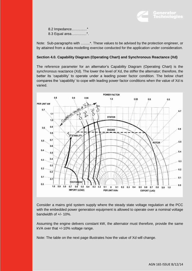
Section 4.0. Capability Diagram (Operating Chart) and Synchronous Reactance (Xd)
The reference parameter for an alternator’s Capability Diagram (Operating Chart) is the
synchronous reactance (Xd). The lower the level of Xd, the stiffer the alternator; therefore, the
better its ‘capability’ to operate under a leading power factor condition. The below chart
compares the ‘capability’ to cope with leading power factor conditions when the value of Xd is
varied.
Consider a mains grid system supply where the steady state voltage regulation at the PCC
with the embedded power generation equipment is allowed to operate over a nominal voltage
bandwidth of +/- 10%.
Assuming the engine delivers constant kW, the alternator must therefore, provide the same
kVA over that +/-10% voltage range.
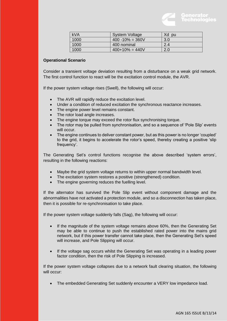
Note: The table on the next page illustrates how the value of Xd will change.
AGN 165 ISSUE B/13/14
kVA System Voltage Xd pu
1000 400 -10% = 360V 3.0
1000 400 nominal 2.4
1000 400+10% = 440V 2.0
Operational Scenario
Consider a transient voltage deviation resulting from a disturbance on a weak grid network.
The first control function to react will be the excitation control module, the AVR.
If the power system voltage rises (Swell), the following will occur:
The AVR will rapidly reduce the excitation level.
Under a condition of reduced excitation the synchronous reactance increases.
The engine power level remains constant.
The rotor load angle increases.
The engine torque may exceed the rotor flux synchronising torque.
The rotor may be pulled from synchronisation, and so a sequence of ‘Pole Slip’ events will occur.
The engine continues to deliver constant power, but as this power is no longer ‘coupled’ to the grid, it begins to accelerate the rotor’s speed, thereby creating a positive ‘slip frequency’.
The Generating Set’s control functions recognise the above described ‘system errors’,
resulting in the following reactions:
Maybe the grid system voltage returns to within upper normal bandwidth level.
The excitation system restores a positive (strengthened) condition.
The engine governing reduces the fuelling level.
If the alternator has survived the Pole Slip event without component damage and the
abnormalities have not activated a protection module, and so a disconnection has taken place,
then it is possible for re-synchronisation to take place.
If the power system voltage suddenly falls (Sag), the following will occur:
If the magnitude of the system voltage remains above 60%, then the Generating Set may be able to continue to push the established rated power into the mains grid network, but if this power transfer cannot take place, then the Generating Set’s speed will increase, and Pole Slipping will occur.
If the voltage sag occurs whilst the Generating Set was operating in a leading power factor condition, then the risk of Pole Slipping is increased.
If the power system voltage collapses due to a network fault clearing situation, the following
will occur:
The embedded Generating Set suddenly encounter a VERY low impedance load.
AGN 165 ISSUE B/14/14
The Generating Set will be unable to transfer established rated power and so the engine speed will increase. The alternator’s stored magnetic energy, in terms of sub-transient and transient reactance values will deliver high fault current levels, consequently imposing high mechanical torque stress levels on the Generating Set’s drive line and structural components.
In the above scenarios, there are so many variables in the sequence of events, that actually
predicting the behaviour and survivability of the Generating Set becomes a risk assessment
exercise rather an engineering calculation. With the operational stresses that are likely to be
encountered, the risk of in-service damage increases.
The latest versions of many country's Grid Codes now clearly expect an embedded Generating
Set to ride through quite sever levels of system disturbance, which previously would have
resulted in the local protection scheme initiating a disconnect. The technical requirements of
such 'ride-through' specifications clearly require very careful consideration on the part of the
design team responsible for any newly proposed embedded generation scheme, and this must
include very careful studies of the likely stresses that will be imposed on the incorporated
alternator. This will; therefore, initiate a technical discussion with the designer of the proposed
alternator, to indicate where robustness needs to be increased and where/what protection
schemes will be incorporated within the overall system to mitigate the risk of alternator
damage.
Consultation with Application Engineering is advised, to consider the technical proposals for
these challenging applications. This AGN has explained the technical situation in length, whilst
offering a route forward when ready to be more specific about a proposed application. The
following information is required, to start initial consideration of a suitable alternator from the
AvK or STAMFORD range:
Proposed level of exported KVA, kVAr.
Operating system Voltage and Frequency, including local Grid Code +/- % limits.
Input power characteristics and stability of input torque to the generator, to comply with
the local Grid Code.
Remember for synchronous generators, your equipment package must include a
method for run-up and synchronisation of the alternator to the host network.
For engagement with Application Engineering, contact [email protected].