Embed Size (px)
DESCRIPTION
particle technology topic related to industry . For chemical engineers.topic is related to agitation and mixing.
Citation preview
Agitation and Mixing of Liquids
Unit IV
Agitation and Mixing
• Agitation : the induced motion of a material in a circulatory pattern
• Mixing :the random distribution of two or more separate phases
• Agitation of low to moderate viscosity and the mixing of liquids, liquid-gas dispersion and liquid-solid suspension
Purposes of agitation:
1. Suspending solid particles (suspension)2. Blending miscible liquids (alcohol & water)3. Dispersing a gas through the liquid (bubble)4. Dispersing immiscible liquids (emulsion)5. Promoting heat transfer between the liquid
and coil or jacket
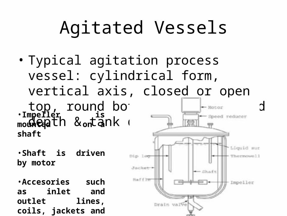
Agitated Vessels
• Typical agitation process vessel: cylindrical form, vertical axis, closed or open top, round bottom, equal liquid depth & tank diameter
•Impeller is mounted on a shaft
•Shaft is driven by motor
•Accesories such as inlet and outlet lines, coils, jackets and wells for thermometer
Impellers
• Impellers are divided into two classes:• Axial-flow impellers : generate currents parallel
with the axis of impeller• Radial-flow impellers : generate currents in
tangential or radial direction
• Impellers for low-to moderate-viscosity liquids: – propellers, turbines & high efficiency impellers
• Impellers for very viscous liquids:– helical impellers & anchor, paddle agitators
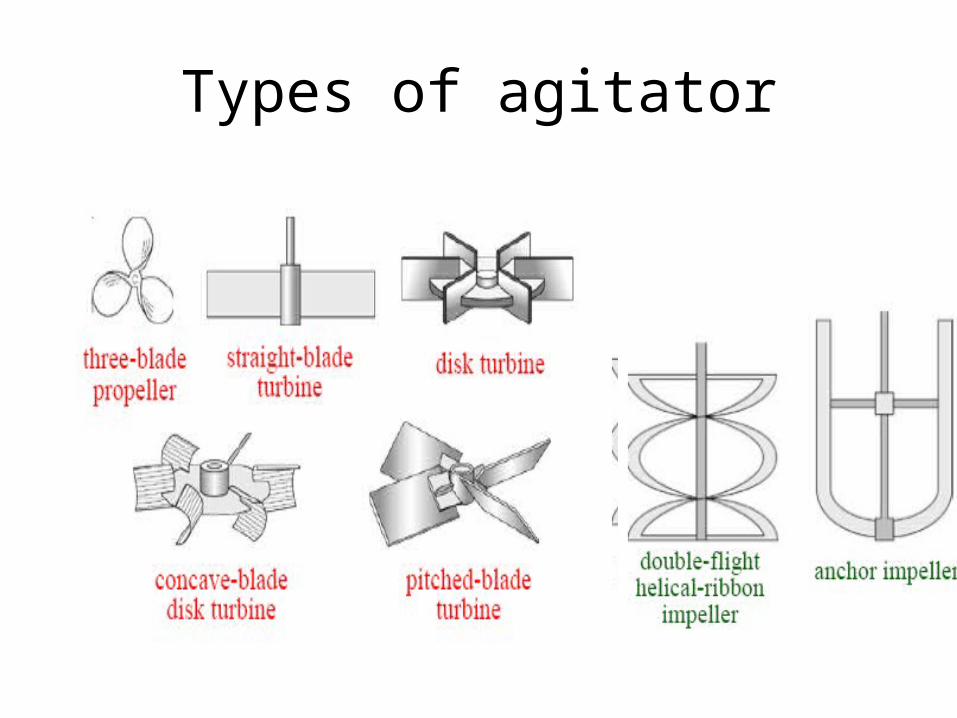
Types of agitator
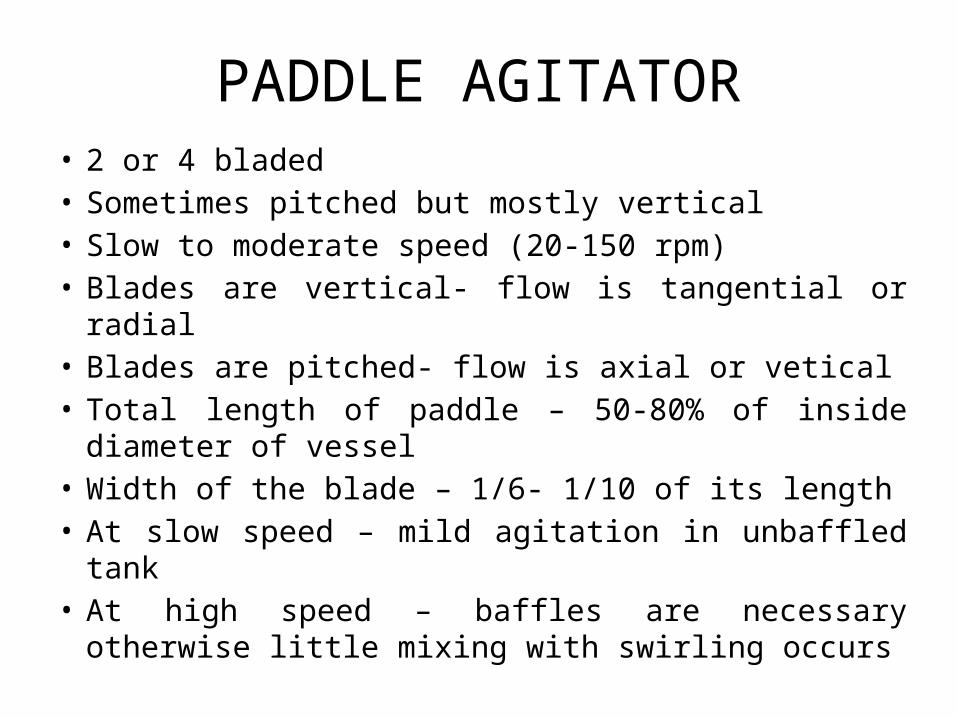
PADDLE AGITATOR• 2 or 4 bladed• Sometimes pitched but mostly vertical• Slow to moderate speed (20-150 rpm)• Blades are vertical- flow is tangential or radial• Blades are pitched- flow is axial or vetical• Total length of paddle – 50-80% of inside diameter of
vessel• Width of the blade – 1/6- 1/10 of its length• At slow speed – mild agitation in unbaffled tank• At high speed – baffles are necessary otherwise little
mixing with swirling occurs
Anchor agitator
• Slow speed and poor mixing
• Scrap the surface or pass over it with close clearance
• So used to prevent the deposits on the heat transfer surface, as in jacketted process vessels
• Poor mixer- used in conjunction with high speed paddle ot other agitator, turning in opposite direction
Turbine agitator
• Multibladed paddle agitator with short blades & turning at high speed
• Blades: vertical or pitched, straight or curved• Diameter of impeller- 30-50 % of vessel diameter• Flow is radial and tangential• Tangential flow- reduced by baffles or diffuser
ring• Effective over a wide range of viscosities
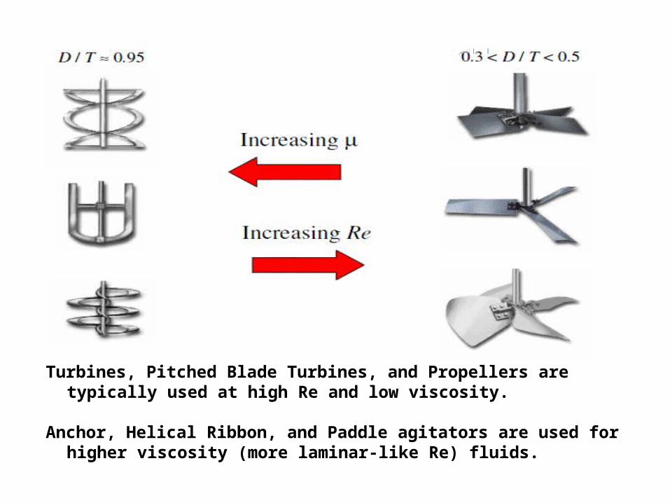
Turbines, Pitched Blade Turbines, and Propellers are typically used at high Re and low viscosity.
Anchor, Helical Ribbon, and Paddle agitators are used for higher viscosity (more laminar-like Re) fluids.
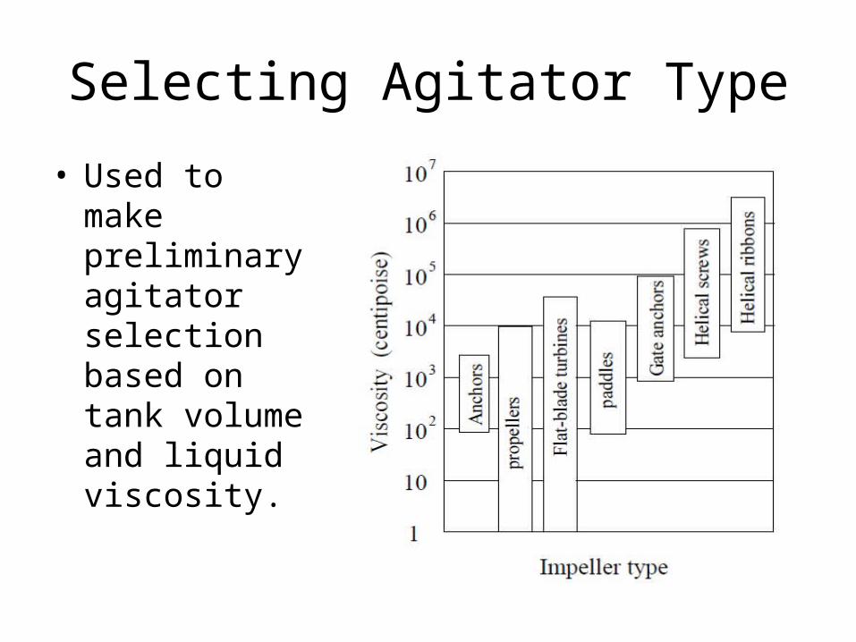
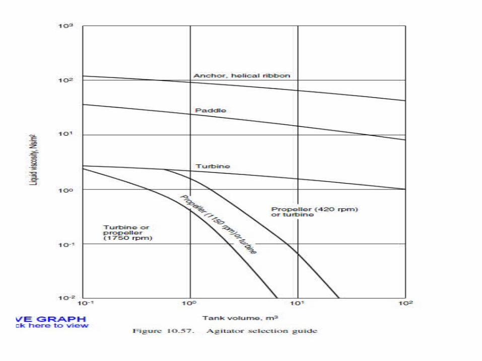
Selecting Agitator Type
• Used to make preliminary agitator selection based on tank volume and liquid viscosity.
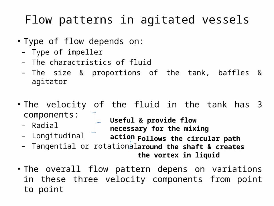
Flow patterns in agitated vessels• Type of flow depends on:– Type of impeller– The charactristics of fluid– The size & proportions of the tank, baffles & agitator
• The velocity of the fluid in the tank has 3 components:– Radial– Longitudinal– Tangential or rotational
• The overall flow pattern depens on variations in these three velocity components from point to point
Useful & provide flow necessary for the mixing action
Follows the circular path around the shaft & creates the vortex in liquid
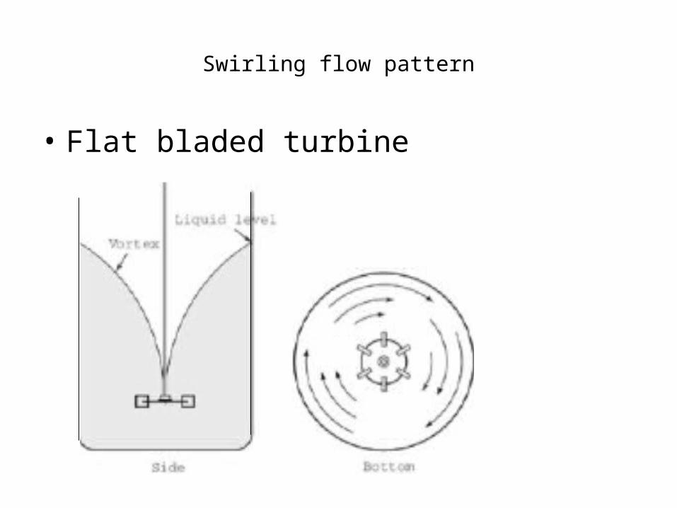
Swirling flow pattern
• Flat bladed turbine
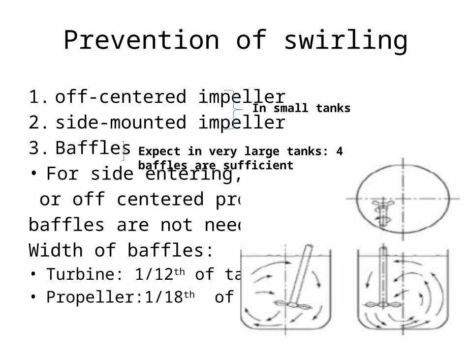
Prevention of swirling
1. off-centered impeller
2. side-mounted impeller
3. Baffles• For side entering, inclined
or off centered propellers
baffles are not needed
Width of baffles:• Turbine: 1/12th of tank dia.• Propeller:1/18th of tank dia.
In small tanks
Expect in very large tanks: 4 baffles are sufficient
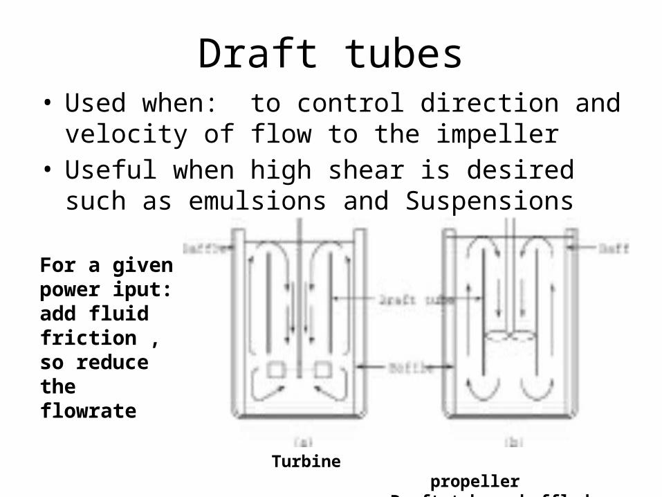
Draft tubes• Used when: to control direction and velocity of flow
to the impeller• Useful when high shear is desired such as emulsions
and Suspensions
Turbine propeller Draft tubes, baffled tank
For a given power iput: add fluid friction , so reduce the flowrate
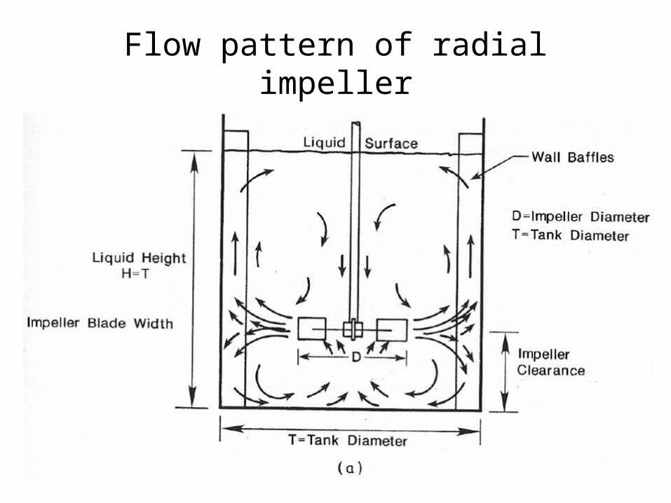
Flow pattern of radial impeller
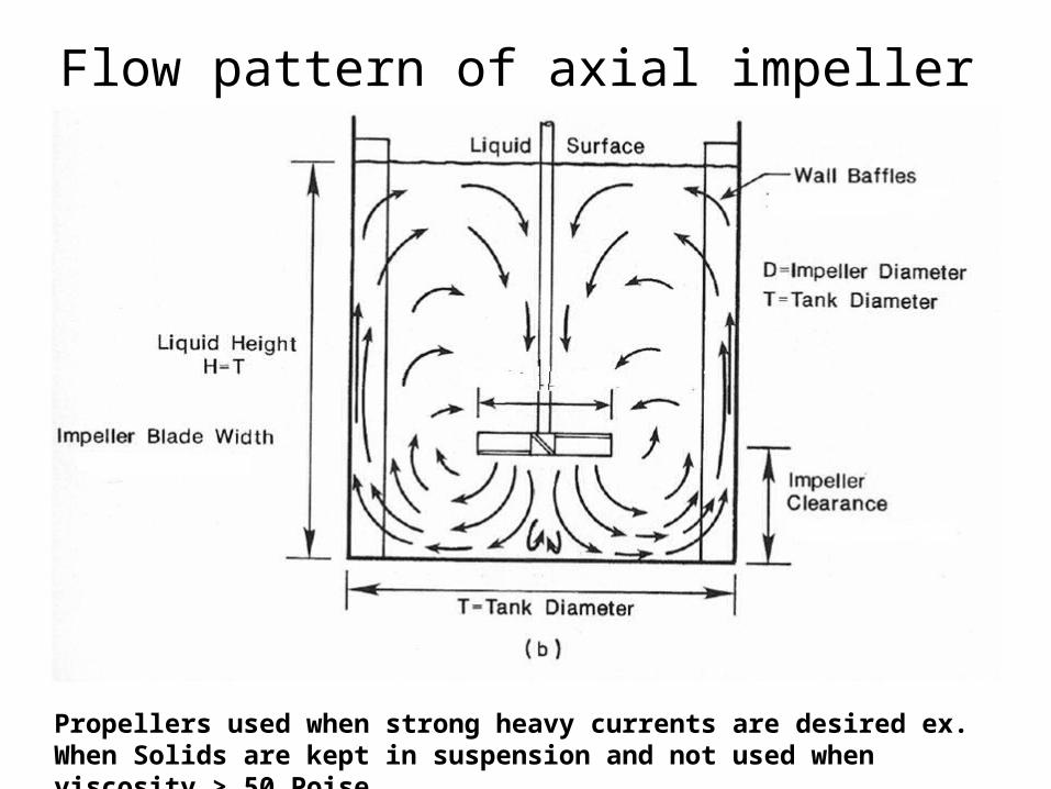
Flow pattern of axial impeller
Propellers used when strong heavy currents are desired ex. When Solids are kept in suspension and not used when viscosity > 50 Poise.
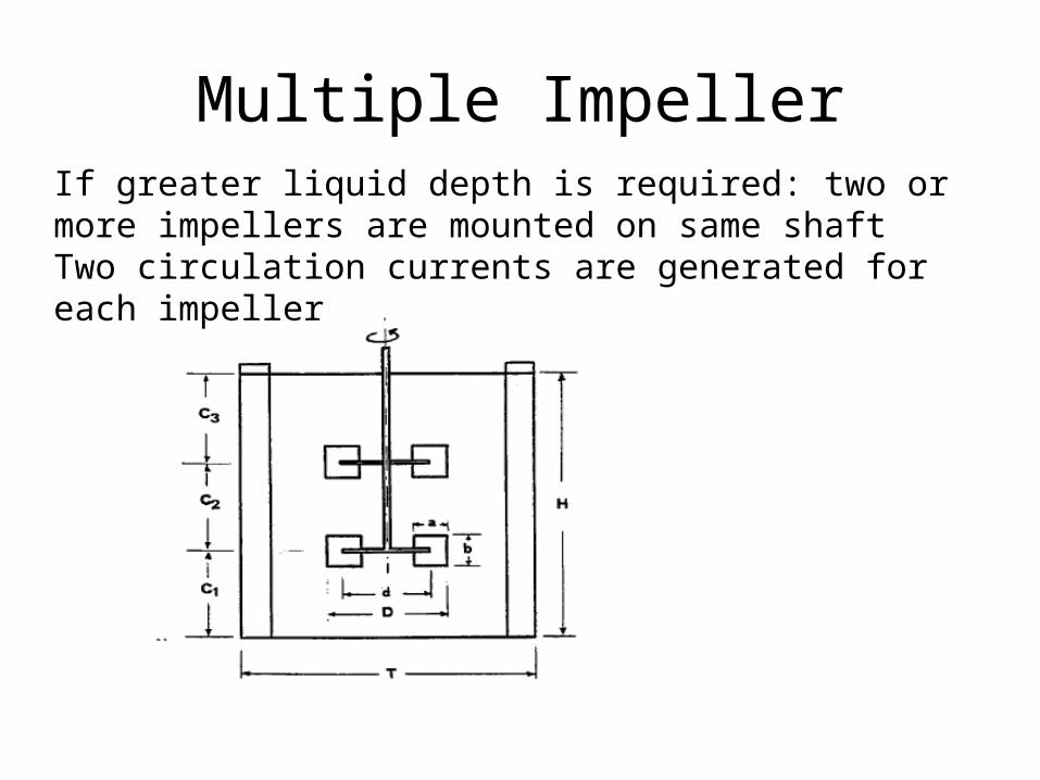
Multiple ImpellerIf greater liquid depth is required: two or more impellers are mounted on same shaftTwo circulation currents are generated for each impeller
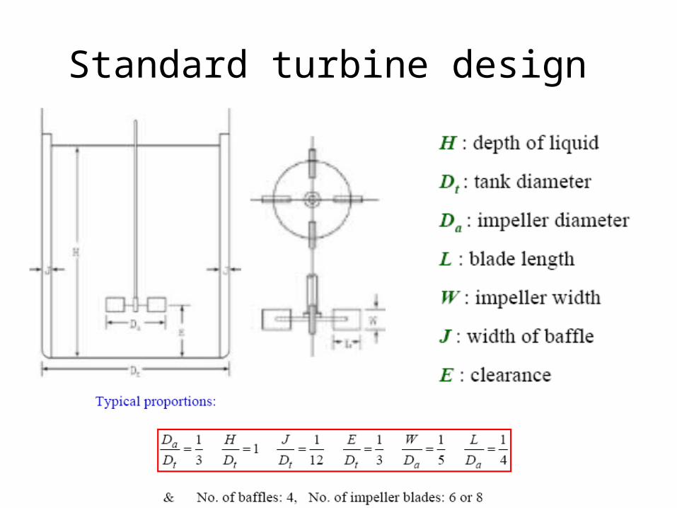
Standard turbine design
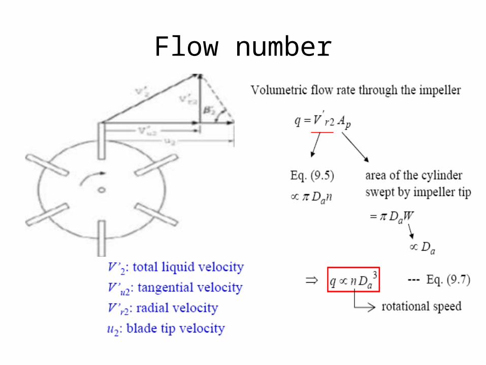
Flow number
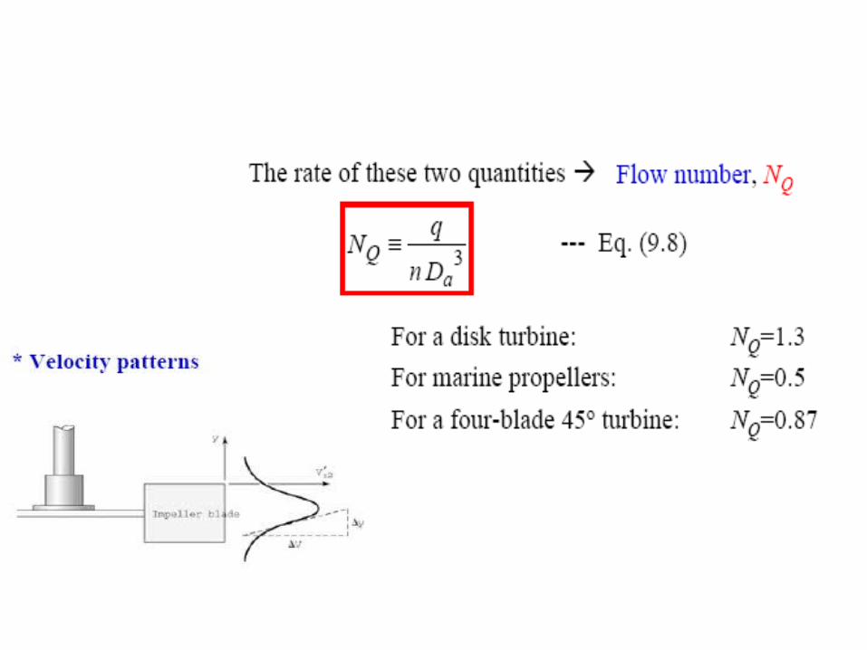
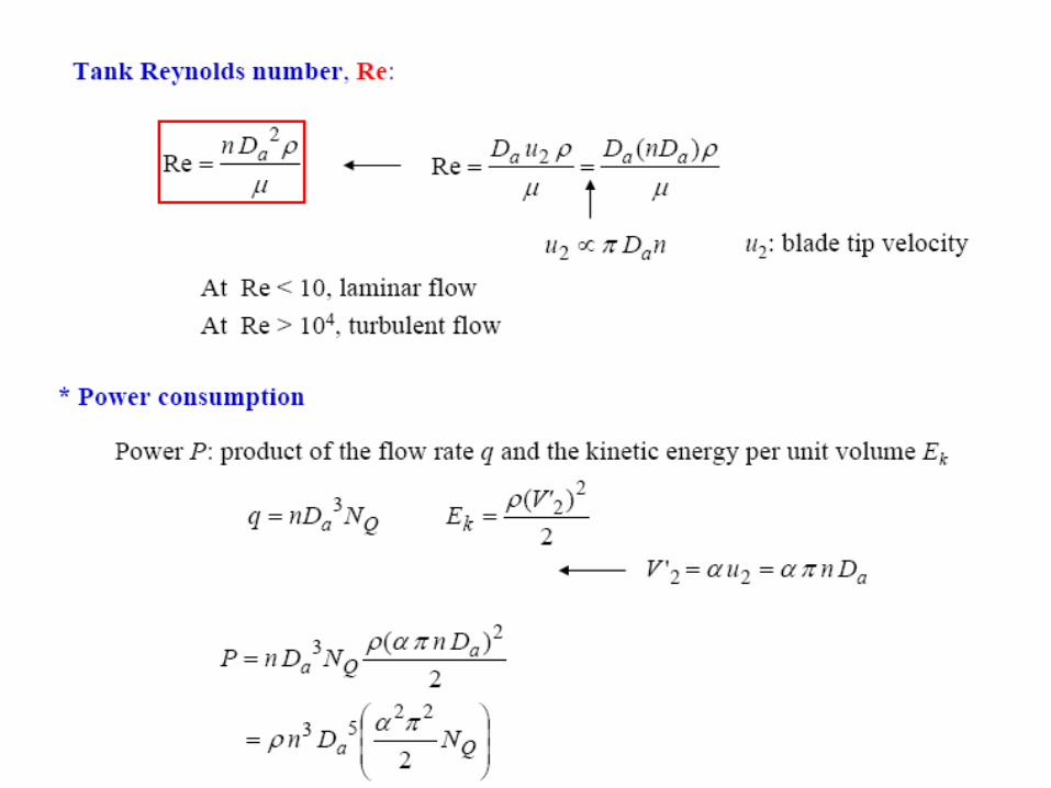
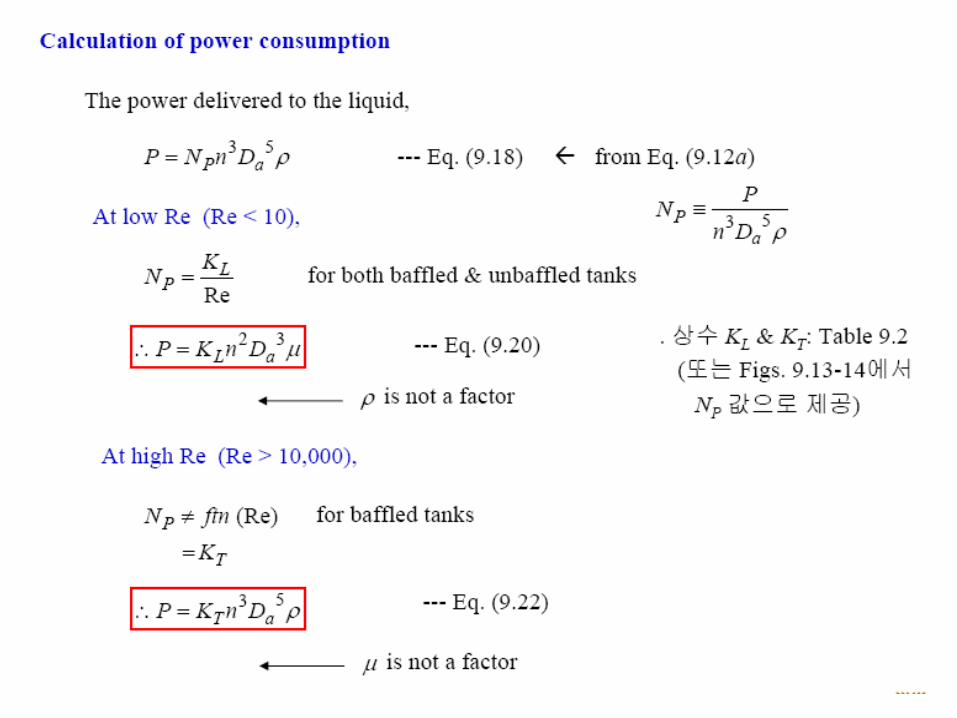
POWER CONSUMPTION
• Power consumption depends on– Shape and dimensions of impeller and vessel as
well as baffles– Density, viscosity of fluid– Frequency of rotation– Additional dependency on acceleration due to
gravity g
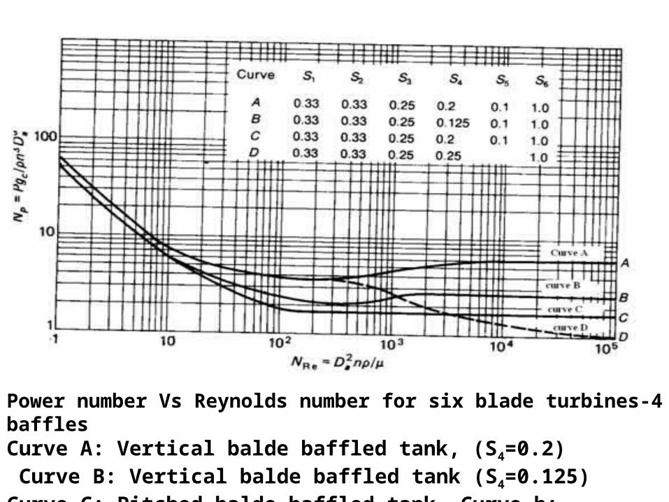
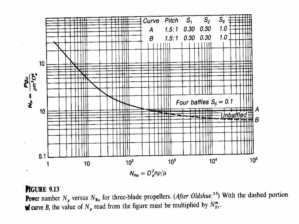
Power number Vs Reynolds number for six blade turbines-4 bafflesCurve A: Vertical balde baffled tank, (S4=0.2) Curve B: Vertical balde baffled tank (S4=0.125)Curve C: Pitched balde baffled tank, Curve b: Vertical balde Unbaffled tank
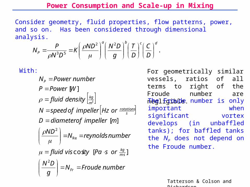
Power Consumption and Scale-up in Mixing
Consider geometry, fluid properties, flow patterns, power, and so on. Has been considered through dimensional analysis.
Tatterson & Colson and Richardson.
...22
53
dcba
P D
C
D
T
g
DNNDK
DN
PN
With:
numberFroudeNg
DN
orsPaityvisfluid
numberreynoldsNND
mimpellerofdiameterD
orHzimpellerofspeedN
densityfluid
WPowerP
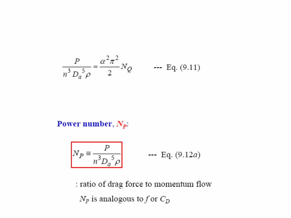
numberPowerN
Fr
smkg
srotations
m
kg
P
2
Re
2
][cos
][
][
3
For geometrically similar vessels, ratios of all terms to right of the Froude number are negligible.
The Froude number is only important when significant vortex develops (in unbaffled tanks); for baffled tanks the NP does not depend on the Froude number.
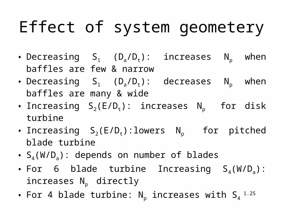
Effect of system geometery
• Decreasing S1 (Da/Dt): increases Np when baffles are few & narrow
• Decreasing S1 (Da/Dt): decreases Np when baffles are many & wide
• Increasing S2(E/Dt): increases Np for disk turbine
• Increasing S2(E/Dt):lowers Np for pitched blade turbine
• S4(W/Da): depends on number of blades
• For 6 blade turbine Increasing S4(W/Da): increases Np directly
• For 4 blade turbine: Np increases with S4 1.25
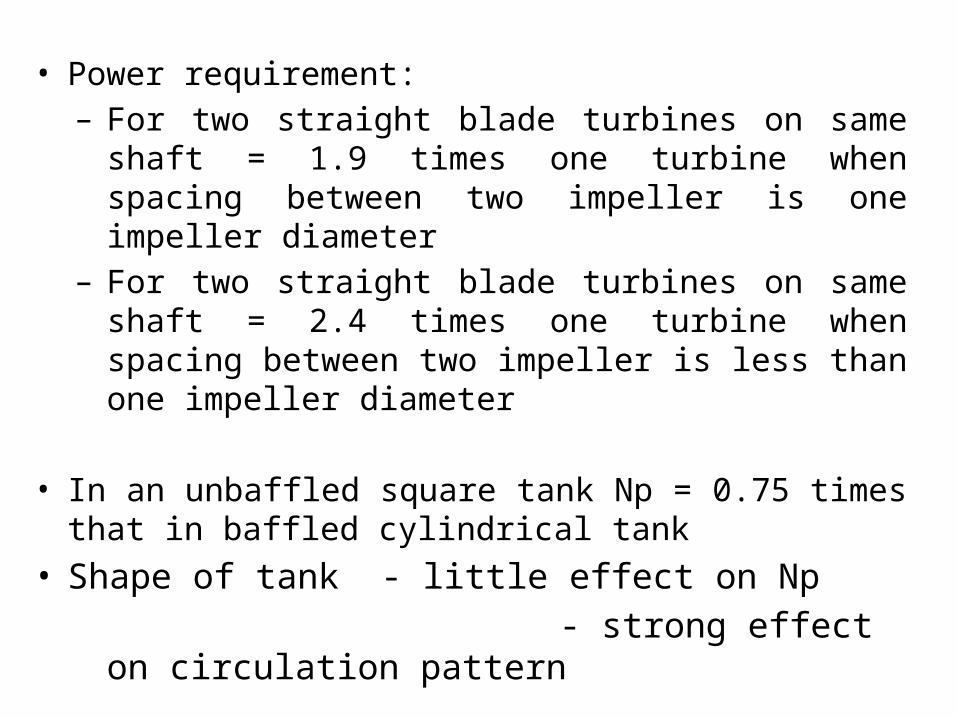
• Power requirement:– For two straight blade turbines on same shaft = 1.9 times
one turbine when spacing between two impeller is one impeller diameter
– For two straight blade turbines on same shaft = 2.4 times one turbine when spacing between two impeller is less than one impeller diameter
• In an unbaffled square tank Np = 0.75 times that in baffled cylindrical tank
• Shape of tank - little effect on Np
- strong effect on circulation pattern
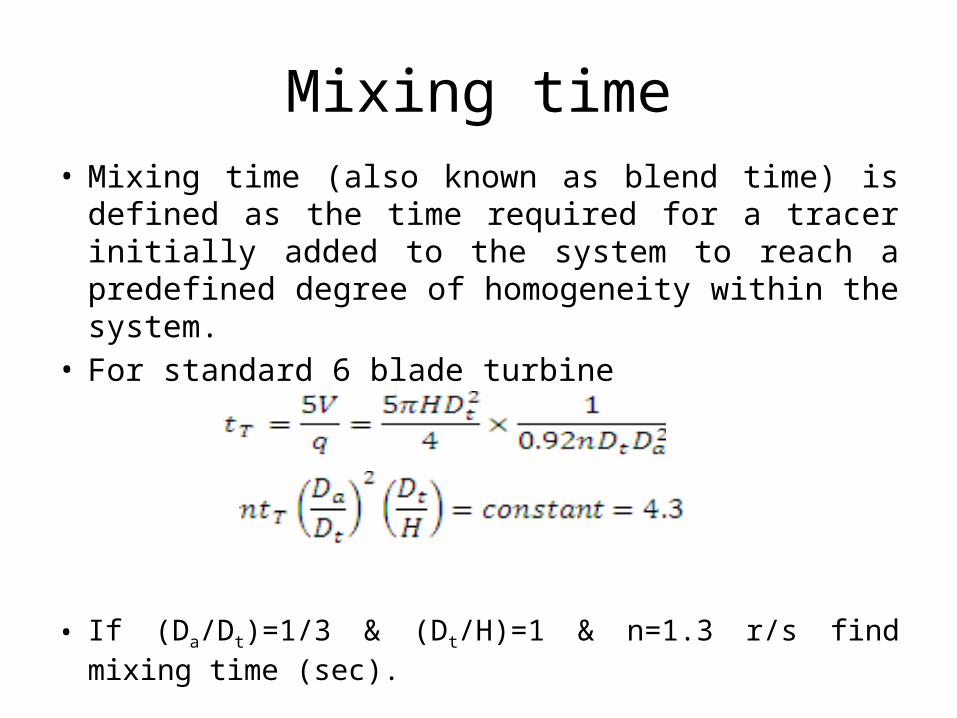
Mixing time• Mixing time (also known as blend time) is defined as the
time required for a tracer initially added to the system to reach a predefined degree of homogeneity within the system.
• For standard 6 blade turbine
• If (Da/Dt)=1/3 & (Dt/H)=1 & n=1.3 r/s find mixing time (sec).
Suspension of solid particles• Important operations in solid-liquid mixing :solid suspension
and dispersion in a liquid
• Degrees of suspension1. Nearly complete suspension with filleting2. Complete particle motion3. Complete suspension or complete off bottom suspension4. Uniform suspension
• The primary objective of solid—liquid mixing :– to create and maintain a solid-liquid slurry, and– to promote and enhance the rate of mass transfer between the
solid and liquid phases.– To catalyze the chemical reaction– To promote the growth of crystalline product
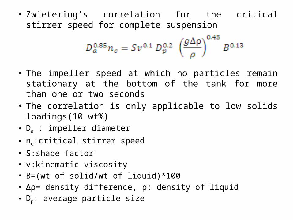
• Zwietering’s correlation for the critical stirrer speed for complete suspension
• The impeller speed at which no particles remain stationary at the bottom of the tank for more than one or two seconds
• The correlation is only applicable to low solids loadings(10 wt%)
• Da : impeller diameter
• nc:critical stirrer speed
• S:shape factor• v:kinematic viscosity• B=(wt of solid/wt of liquid)*100• Δρ= density difference, ρ: density of liquid
• Dp: average particle size
Mixers• Mixers are meant to shift the non-homogeneity of a batch
to a homogenous state.• Employed both for solids and liquids phases• Blending of ingredients, cooling or heating purposes,
drying or roasting of solids, reaction engineering, coatings, agglomeration or even size reduction
• More power required for mixing pastes and dry solids than in blending liquids
Mixers for cohesive solids
• Most difficult : mixing of cohesive solids such as pastes, plastic materials and rubber.
• Viscosity is very high
• For cohesive solids- mixers can not generate the flow currents instead they shear, fold, stretch & compress the material to be mixed
• Mixers for cohesive solids: pastes, plastic & rubber– Change can, kneader, pug mill, pan mixer, mixer
extruder, mixer rolls
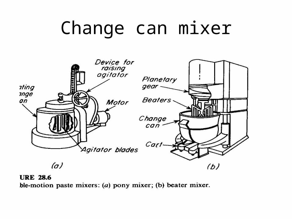
Change Can Mixer• Can handle viscous liquid & light pastes as in
food processing & paint industries.
• 1) Pony mixer:• Agitator has several vertical blades mounted on a vertical
shaft (positioned near the wall ) rotating in one direction while can or container counter rotates
• The agitator shaft is usually mounted on a hinged structure so that it can raised, lifting the blades out of can.
• The blades are wiped clean that permits the can to be removed , emptied and can be replaced easily with new batch.
Change Can Mixer
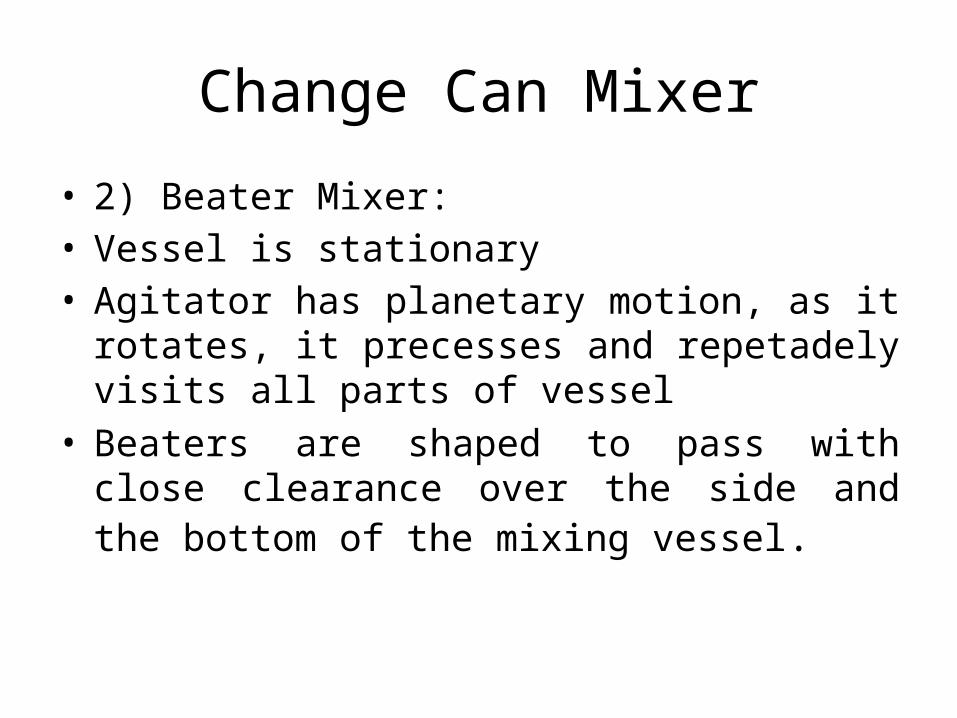
• 2) Beater Mixer: • Vessel is stationary• Agitator has planetary motion, as it rotates, it
precesses and repetadely visits all parts of vessel• Beaters are shaped to pass with close clearance over
the side and the bottom of the mixing vessel.
Change can mixer
Kneader mixer• Kneading is the method of mixing used with deformable or
plastic solids• Involves: squashing the mass flat, folding it over on itself
and squashing it once more• Also tear the mass apart and shear it between moving blade
and stationary surface.• Two arm kneader: suspension, pastes and light
plastic masses• Disperser : heavier than kneader & draws more power– is suitable for additives and coloring agents into stiff
materials.• Masticator: still heavier & draws even more power, called as
intensive mixer
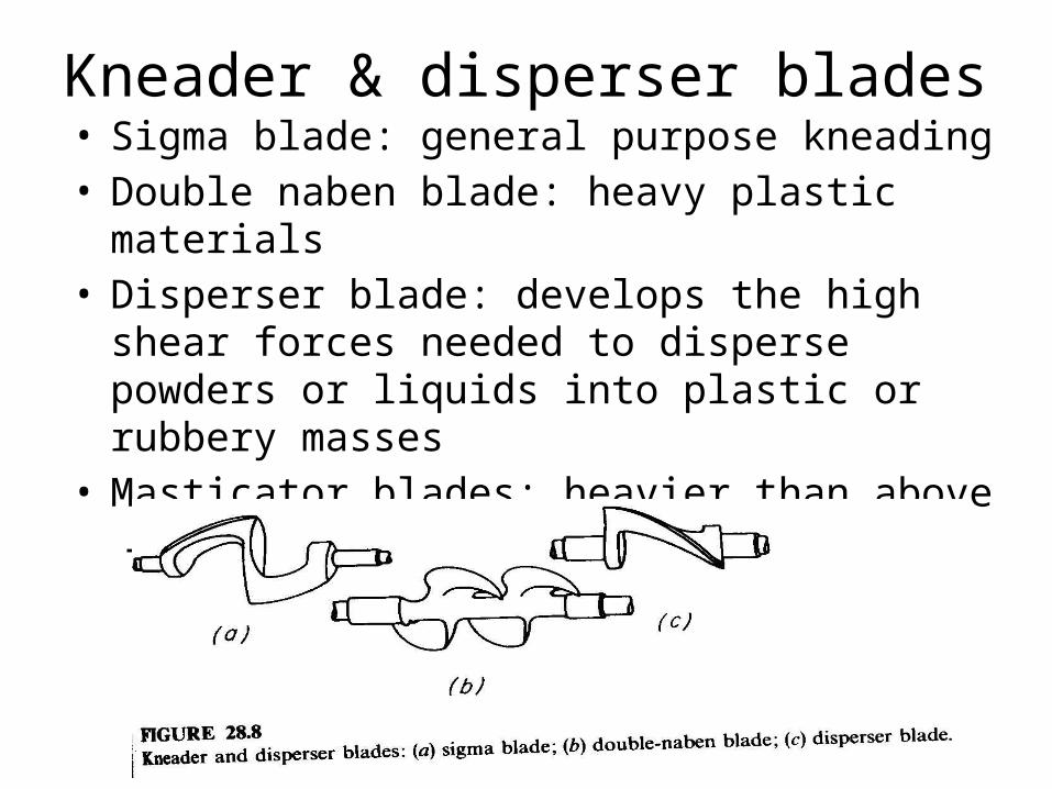
Kneader & disperser blades• Sigma blade: general purpose kneading• Double naben blade: heavy plastic materials• Disperser blade: develops the high shear forces
needed to disperse powders or liquids into plastic or rubbery masses
• Masticator blades: heavier than above – Spiral , flattened and elliptical shapes
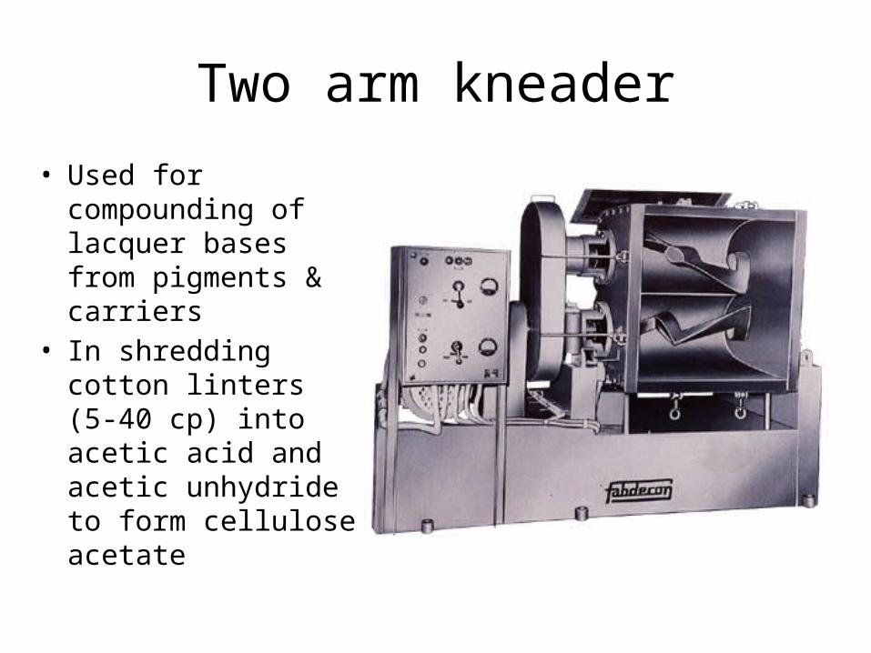
Two arm kneader
• Used for compounding of lacquer bases from pigments & carriers
• In shredding cotton linters (5-40 cp) into acetic acid and acetic unhydride to form cellulose acetate
Banbury mixer
• Called as internal mixers: mixing chamber is closed• Rubber is always compounded with additives• Such as sulfur for vulcanization, fillers to enhance the
rubber's mechanical properties, antioxidants, plasticizers, coloring pigments
• The additives must be thoroughly mixed with the base rubber to achieve uniform dispersion of ingredients
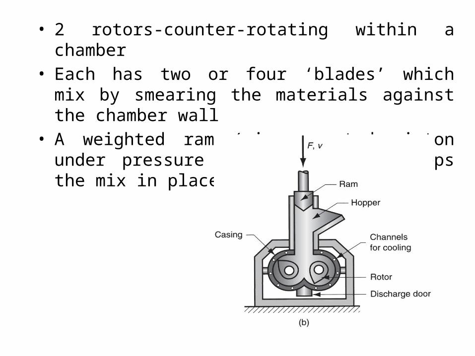
• 2 rotors-counter-rotating within a chamber• Each has two or four ‘blades’ which mix by smearing the
materials against the chamber wall• A weighted ram (air operated piston under pressure 1-10
atm press) keeps the mix in place inside the chamber
Pug mill• Blades or knives in a helical pattern on a horizontal shaft
turning in an open trough or close cylinder• Solids enter at one end and discharge at other end• In chamber they are cut, mixed and move forward to be
acted upon by succeeding blades• Single shaft mills- used enclosed mixing chamber• Double shaft – used when more through or rapid mixing is
required• Chamber is cylindrical or polygonal for sticky materials• Sometimes operate under vacuum to remove the air from
clay or other materials• Built with jackets with heating or cooling
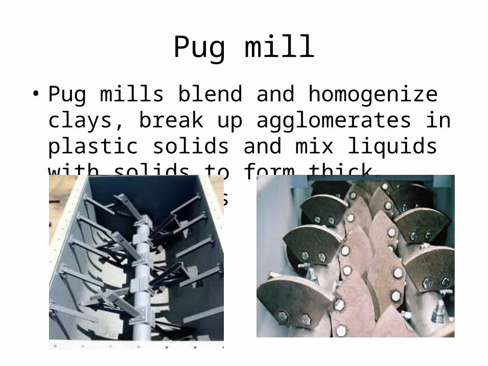
Pug mill• Pug mills blend and homogenize clays, break
up agglomerates in plastic solids and mix liquids with solids to form thick, heavy slurries
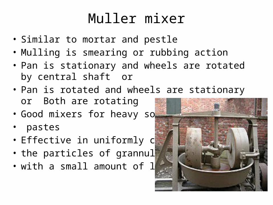
Muller mixer• Similar to mortar and pestle• Mulling is smearing or rubbing action• Pan is stationary and wheels are rotated by central shaft or • Pan is rotated and wheels are stationary or Both are
rotating• Good mixers for heavy solids & • pastes• Effective in uniformly coating • the particles of grannular solid • with a small amount of liquid
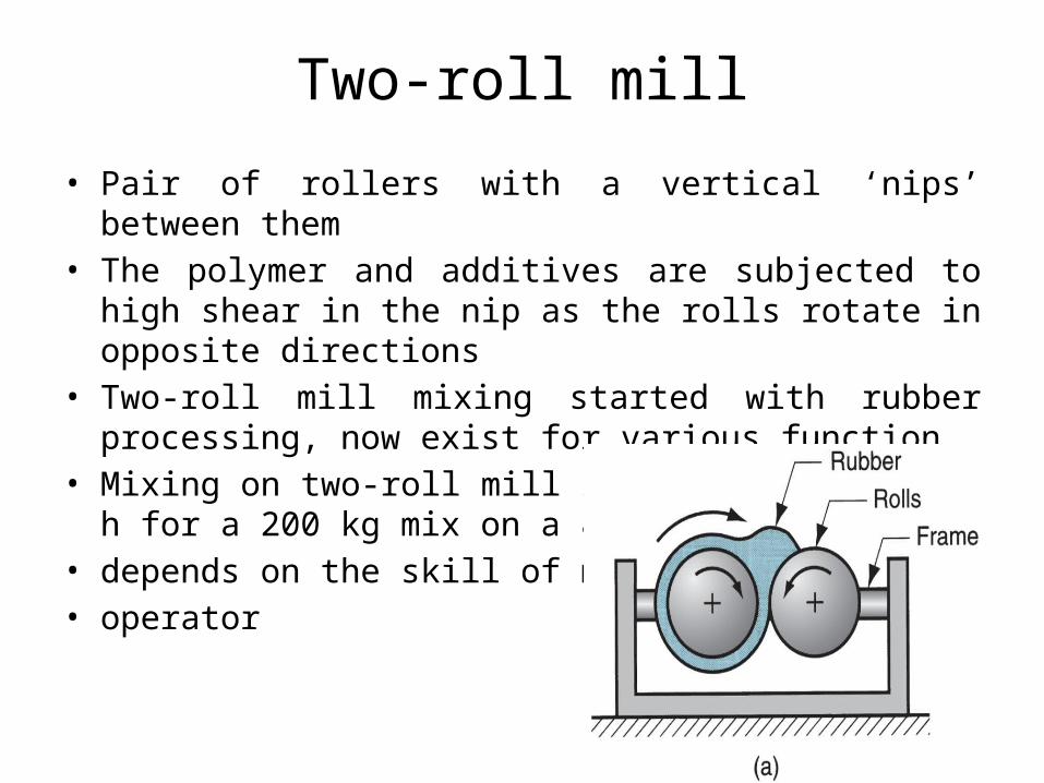
Two-roll mill
• Pair of rollers with a vertical ‘nips’ between them• The polymer and additives are subjected to high shear in the
nip as the rolls rotate in opposite directions• Two-roll mill mixing started with rubber processing, now exist
for various function• Mixing on two-roll mill is time consuming, 2 h for a 200 kg
mix on a 84” wide mill, and • depends on the skill of mill • operator
• Mixers for free flowing solids: – Ribbon blender, – internal screw, – tumbling mixer, – impact wheels
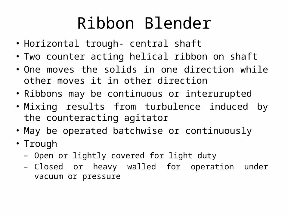
Ribbon Blender• Horizontal trough- central shaft • Two counter acting helical ribbon on shaft• One moves the solids in one direction while other
moves it in other direction• Ribbons may be continuous or interurupted• Mixing results from turbulence induced by the
counteracting agitator• May be operated batchwise or continuously• Trough – Open or lightly covered for light duty– Closed or heavy walled for operation under vacuum or
pressure
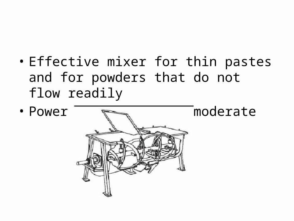
• Effective mixer for thin pastes and for powders that do not flow readily
• Power requirement is moderate
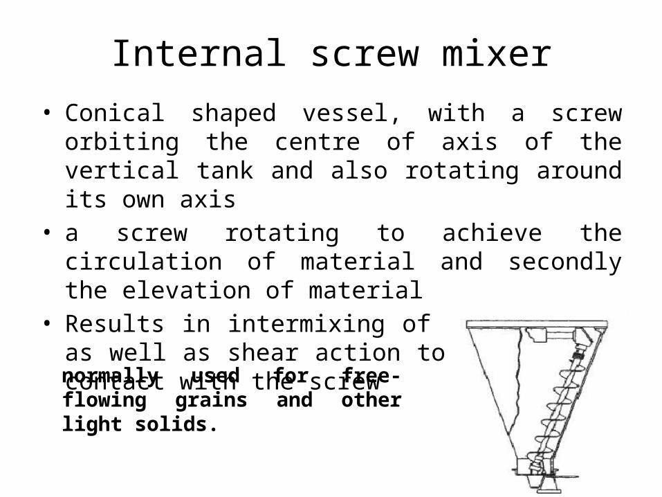
Internal screw mixer
• Conical shaped vessel, with a screw orbiting the centre of axis of the vertical tank and also rotating around its own axis
• a screw rotating to achieve the circulation of material and secondly the elevation of material
• Results in intermixing of solid grains as well as shear action to the ones in contact with the screw
normally used for free-flowing grains and other light solids.
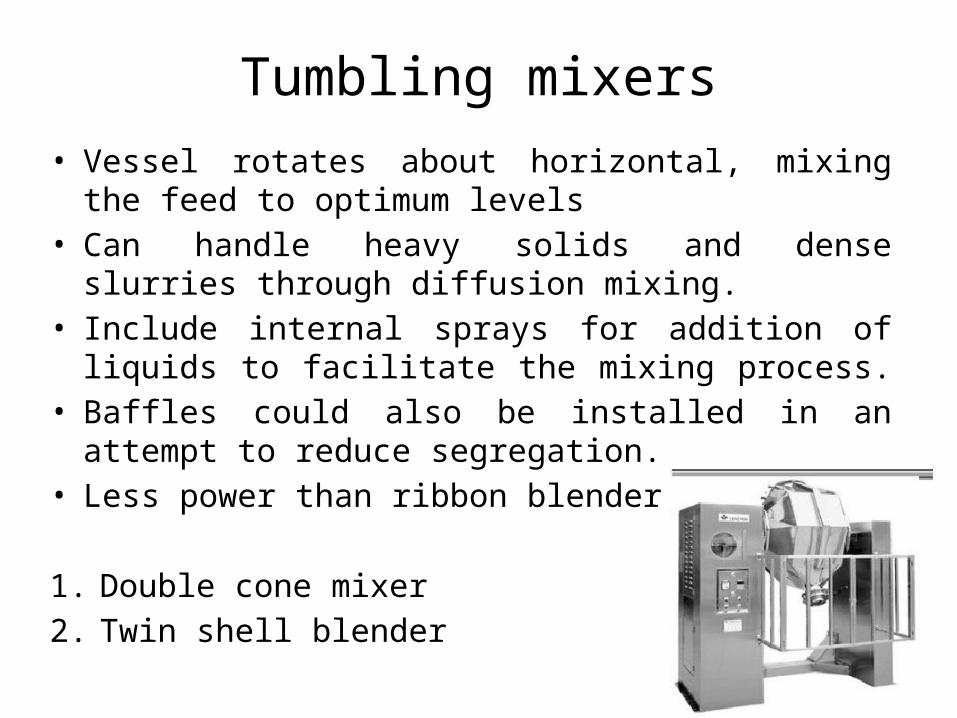
Tumbling mixers
• Vessel rotates about horizontal, mixing the feed to optimum levels
• Can handle heavy solids and dense slurries through diffusion mixing.
• Include internal sprays for addition of liquids to facilitate the mixing process.
• Baffles could also be installed in an attempt to reduce segregation.
• Less power than ribbon blender
1. Double cone mixer
2. Twin shell blender
Mixing index


![FF0 Agitation Mixing [Compatibility Mode]](https://img.pdfslide.us/doc/110x75/547accafb4af9fc3158b4c62/ff0-agitation-mixing-compatibility-mode.jpg)