Embed Size (px)
Citation preview
SPECIFICATION
INSTALLATION INSTRUCTIONS
Note
Note
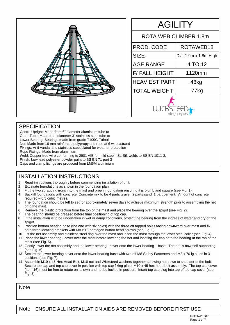
PROD. CODE
SIZE
AGE RANGE
F/ FALL HEIGHT
HEAVIEST PART
TOTAL WEIGHT
AGILITYROTA WEB CLIMBER 1.8m
ROTAWEB18
Dia. 1.9m x 1.8m High
4 TO 12
1120mm
48kg
77kg
ROTAWEB18Page 1 of 7
Centre Upright: Made from 6" diameter aluminium tube toOuter Tube: Made from diameter 3" stainless steel tube toLower Bearing: Bearings made from grade T100G TufnolNet: Made from 16 mm reinforced polypropylene rope at 6 wires/strandFixings: Anti-vandal and stainless steel/plated for weather protectionRope Fixings: Made from aluminiumWeld: Copper free wire conforming to 2901 AIB for mild steel. St. Stl. welds to BS EN 1011-3.Finish: Low lead polyester powder paint to BS EN 71 part 3Caps and clamp fixings are produced from LM6M aluminium
1234
5
678
9
1011
12
13
14
ENSURE ALL INSTALLATION AIDS ARE REMOVED BEFORE FIRST USE
Read instructions thoroughly before commencing installation of unit.Excavate foundations as shown in the foundation plan.Fit the two spragging irons into the mast and prop in foundation ensuring it is plumb and square (see Fig. 1).Backfill foundations with concrete. Concrete mix to be 4 parts gravel, 2 parts sand, 1 part cement. Amount of concreterequired – 0.5 cubic metres.The foundation should be left to set for approximately seven days to achieve maximum strength prior to assembling the netonto the mast.Remove the plastic protection from the top of the mast and place the bearing over the spigot (see Fig. 2).The bearing should be greased before final positioning of top cap.If the installation is to be undertaken in wet or damp conditions, protect the bearing from the ingress of water and dry off thespigot.Position bottom bearing base (the one with six holes) with the three off tapped holes facing downward over mast and fixonto three locating brackets with M8 x 16 pentagon button head screws (see Fig. 3).Lift the net assembly and stainless steel ring over the mast and insert the mast through the lower steel collar (see Fig. 4).Place the lower bearing - cover over the mast before lowering the net and locating the cap onto the bearing at the top of themast (see Fig. 5).Gently lower the net assembly and the lower bearing - cover onto the lower bearing – base. The net is now self-supporting(see Fig. 6).Secure the lower bearing cover onto the lower bearing base with two off M8 Safety Fasteners and M8 x 70 lg studs in 3positions (see Fig. 7).Assemble M10 x 45 Hex Head Bolt, M10 nut and Wicksteed washers together screwing nut down to shoulder of the bolt.Secure top cap and top cap cover in position with top cap fixing plate, M10 x 45 hex head bolt assembly. The top cap cover(item 16) must be free to rotate on its own and not be locked in position. Insert top cap plug into top of top cap cover (seeFig. 8).
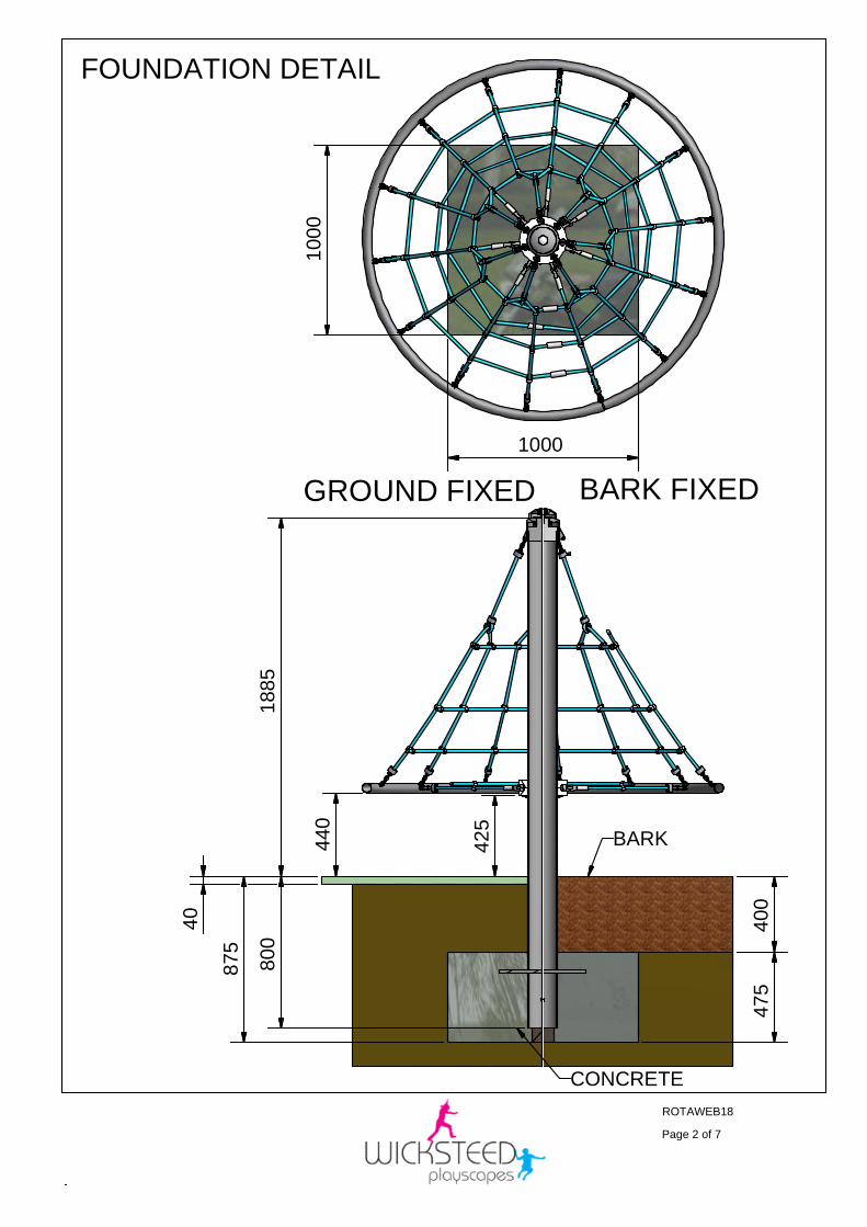
BARK FIXEDGROUND FIXED
ROTAWEB18
Page 2 of 7
FOUNDATION DETAIL
1000
1000
400
475
CONCRETE
BARK425
440
1885
800
875
40
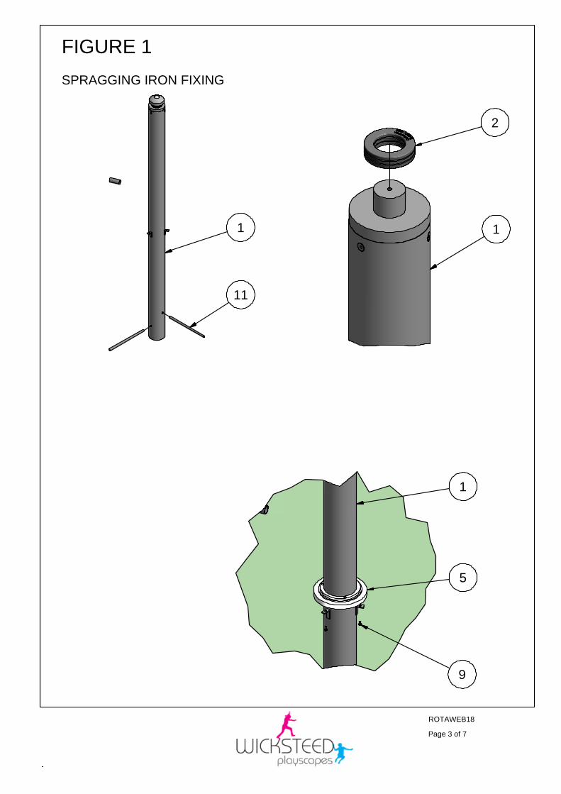
FIGURE 1
SPRAGGING IRON FIXING
ROTAWEB18
Page 3 of 7
1
11
1
1
5
9
2
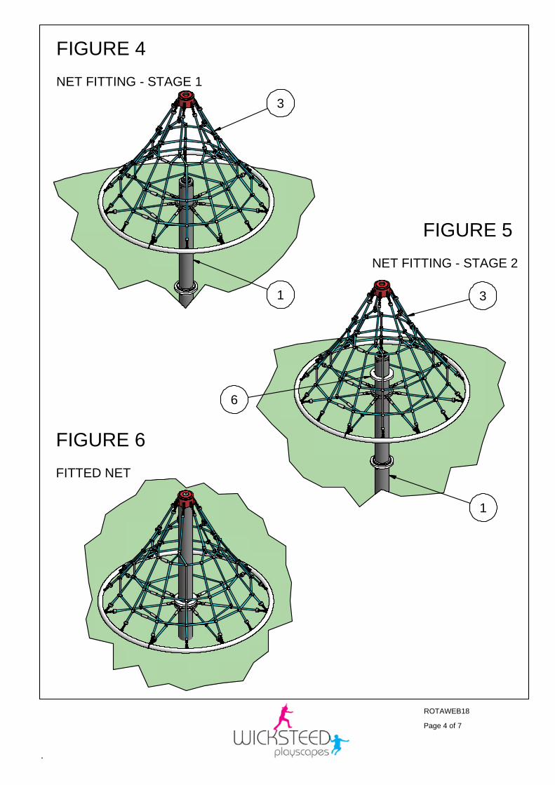
FIGURE 4
NET FITTING - STAGE 1
FIGURE 5
NET FITTING - STAGE 2
FIGURE 6
FITTED NET
ROTAWEB18
Page 4 of 7
1
1
6
3
3
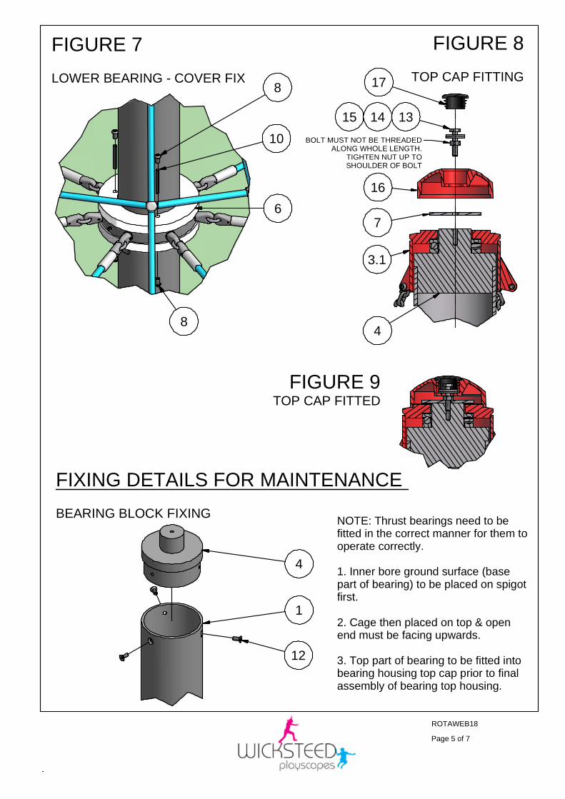
FIGURE 7
LOWER BEARING - COVER FIX
FIXING DETAILS FOR MAINTENANCE
BEARING BLOCK FIXING
FIGURE 8
TOP CAP FITTING
FIGURE 9TOP CAP FITTED
ROTAWEB18
Page 5 of 7
8
8
10
6
4
12
1
17
131415
16
7
4
3.1
BOLT MUST NOT BE THREADEDALONG WHOLE LENGTH.
TIGHTEN NUT UP TOSHOULDER OF BOLT
NOTE: Thrust bearings need to befitted in the correct manner for them tooperate correctly.
1. Inner bore ground surface (basepart of bearing) to be placed on spigotfirst.
2. Cage then placed on top & openend must be facing upwards.
3. Top part of bearing to be fitted intobearing housing top cap prior to finalassembly of bearing top housing.
ROTAWEB18
Page 6 of 7
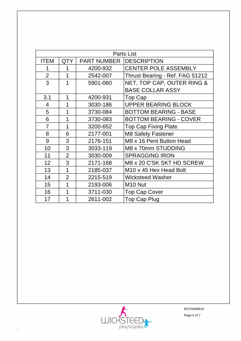
Parts List
DESCRIPTIONPART NUMBERQTYITEM
CENTER POLE ASSEMBLY4200-93211
Thrust Bearing - Ref. FAG 512122542-00712
NET, TOP CAP, OUTER RING &
BASE COLLAR ASSY
5901-06013
Top Cap4200-93113.1
UPPER BEARING BLOCK3030-18614
BOTTOM BEARING - BASE3730-08415
BOTTOM BEARING - COVER3730-08316
Top Cap Fixing Plate3200-65217
M8 Safety Fastener2177-00168
M8 x 16 Pent Button Head2176-15139
M8 x 70mm STUDDING3033-119310
SPRAGGING IRON3030-009211
M8 x 20 C'SK SKT HD SCREW2171-168312
M10 x 45 Hex Head Bolt2185-037113
Wicksteed Washer2215-519214
M10 Nut2193-006115
Top Cap Cover3711-030116
Top Cap Plug2611-002117
REV
ECN
SIG.
DATE:
COMPILED
DATE:
ROTAWEB18
Page 7 of 7
SB
01/08/07
Maintenance & Inspection
General
The ROTAWEB 18-climber should be inspected and maintained in accordance with the recommendations asdetailed in BS EN 1176 part 7: Guidance on installation, inspection, maintenance and operation for PlaygroundEquipment.
If any part of the equipment is found to be unsafe during an inspection and that part cannot be repaired orreplacedimmediately, the equipment unit or the part(s) concerned should be secured against use. This may involveimmobilisation or removal from site.
IMPORTANT NOTE: THE FREQUENCY OF INSPECTION WILL VARY WITH THE TYPE OF EQUIPMENT ORMATERIALS USED AND OTHER FACTORS, E.G. HEAVY USE, LEVELS OF VANDALISM, COASTALLOCATION, AIR POLLUTION, AGE OF EQUIPMENT ETC.
__________________________________________________________________________________________
Routine Visual Inspection
A routine visual inspection enables the identification of obvious hazards that can result from vandalism, use orweather conditions, e.g. broken parts.
A daily routine visual inspection is recommended especially for playground equipment that has heavy use and/oris subject to vandalism and should include the inspection of the following as a minimum:-
a) General equipment and surface cleanliness
b) Equipment ground clearances are maintained
c) Foundations not exposed, loose in the ground or cracked
d) Parts not missing or damaged
e) Surface finishes not damaged, rusting or deteriorating
f) Connections and bolts are secure and tight, locknuts are in place
g) Bearings are free running – grease weekly or more frequently if necessary.
(grease to be ‘castrol mp2 grease speerol 125’ or equivalent)
h) Safety surface (if installed) not compacted, damaged or contaminated with sharp objects.
1
minor
SB
14/11/08
0
1533
SB
01/08/07
2
minor
SB
01/06/09
3
minor
DB
30/07/13
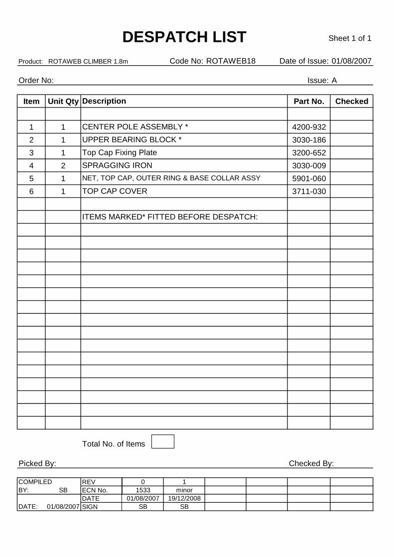
Product: ROTAWEB CLIMBER 1.8m Code No: ROTAWEB18 Date of Issue: 01/08/2007
Order No: Issue: A
Item Unit Qty Part No. Checked
1 1 4200-932
2 1 3030-186
3 1 3200-652
4 2 3030-009
5 1 5901-060
6 1 3711-030
Picked By: Checked By:
COMPILED REV 0 1
BY: SB ECN No. 1533 minor
DATE 01/08/2007 19/12/2008
DATE: 01/08/2007 SIGN SB SB
Total No. of Items
DESPATCH LIST
Description
CENTER POLE ASSEMBLY *
Sheet 1 of 1
UPPER BEARING BLOCK *
Top Cap Fixing Plate
SPRAGGING IRON
NET, TOP CAP, OUTER RING & BASE COLLAR ASSY
TOP CAP COVER
ITEMS MARKED* FITTED BEFORE DESPATCH:
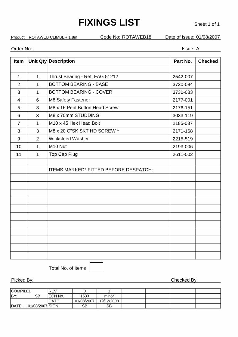
Product: ROTAWEB CLIMBER 1.8m Code No: ROTAWEB18 Date of Issue: 01/08/2007
Order No: Issue: A
Item Unit Qty Part No. Checked
1 1 2542-007
2 1 3730-084
3 1 3730-083
4 6 2177-001
5 3 2176-151
6 3 3033-119
7 1 2185-0378 3 2171-168
9 2 2215-519
10 1 2193-006
11 1 2611-002
Picked By: Checked By:
COMPILED REV 0 1
BY: SB ECN No. 1533 minor
DATE 01/08/2007 19/12/2008
DATE: 01/08/2007 SIGN SB SB
Sheet 1 of 1
Thrust Bearing - Ref. FAG 51212
ITEMS MARKED* FITTED BEFORE DESPATCH:
M8 x 20 C"SK SKT HD SCREW *
BOTTOM BEARING - COVER
M8 Safety Fastener
M8 x 16 Pent Button Head Screw
Total No. of Items
FIXINGS LIST
Description
BOTTOM BEARING - BASE
M8 x 70mm STUDDING
M10 x 45 Hex Head Bolt
Wicksteed Washer
M10 Nut
Top Cap Plug