Embed Size (px)
Citation preview
Agilent Technologies
Need Help with Power Products?www.agilent.com/find/power
Agilent
Power Products
Catalog 2002-2003
Application Information and Technical Data for:
dc Power Supplies
dc Electronic Loads
ac Power Solutions
Application-Specific Power Solutions• Mobile Communications dc Sources• Solar Array Simulators• Component Test dc Source• Multi-Cell Charger/Discharger
Power Products Modification Service

One quick browse through
this catalog will convince you
that Agilent power products
offer so much more than
simple power generation. In
each product category, we’ve
integrated the capabilities you
need for a complete power
solution, including extensive
measurement and analysis
capabilities.
The cost and performance
benefits of the one-box approach
The central theme in all our power
products is one-box integration–
giving you a complete test solution
for the price of a single instrument.
The one-box approach improves
test results while cutting costs,
complexity and rack size. These
solutions are much easier to inte-
grate, program and maintain in ATE
systems. Another major benefit is
that we specify and guarantee per-
formance for the entire integrated
system, so you know what you’re
really dealing with–unlike the
typical “rack-and-stack” setup.
Power you can count on year after year
We’ve been a leader in the power
products business for more than
four decades because engineers like
you know they can count on Agilent
Agilent Technologies
s o l u t i o n s to match your new test and measurement
challenges. From Power Supplies
to Power Solutions
performance and reliability. Even
our least-expensive dc supplies
offer low ripple and noise with
tight load and line regulation. Our
high-precision products give you
exacting control over power output
levels, with accurate readback
measurements to match. Plus,
every Agilent power product in
this catalog is covered by a three-
year warranty (except where noted).
We know you have more important
things to do than shop around for
power supplies. That’s why we’ve
made such a wide range of products
available through Agilent. The
experienced engineers at Agilent
can help you select just the right
solutions for your application and
your budget, then arrange fast
shipping so you can get to work
in a hurry.
www.agilent.com/find/power
1
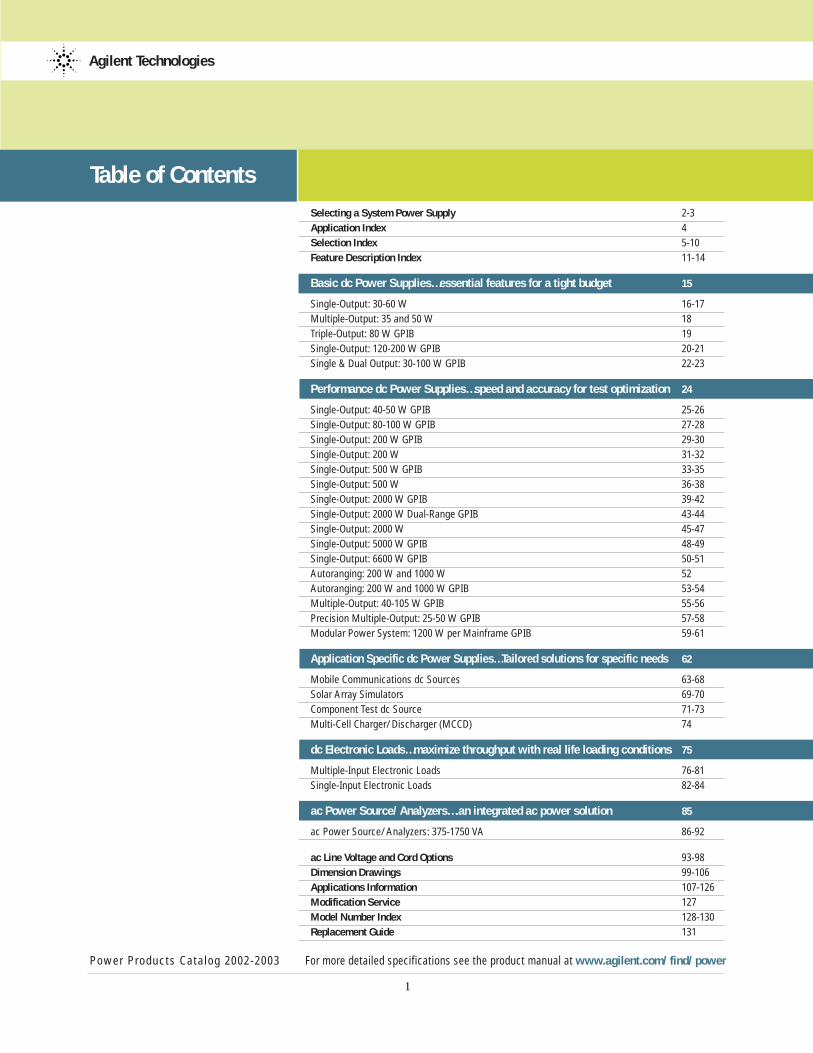
Table of Contents
Selecting a System Power Supply 2-3
Application Index 4
Selection Index 5-10
Feature Description Index 11-14
Basic dc Power Supplies…essential features for a tight budget 15
Single-Output: 30-60 W 16-17
Multiple-Output: 35 and 50 W 18
Triple-Output: 80 W GPIB 19
Single-Output: 120-200 W GPIB 20-21
Single & Dual Output: 30-100 W GPIB 22-23
Performance dc Power Supplies…speed and accuracy for test optimization 24
Single-Output: 40-50 W GPIB 25-26
Single-Output: 80-100 W GPIB 27-28
Single-Output: 200 W GPIB 29-30
Single-Output: 200 W 31-32
Single-Output: 500 W GPIB 33-35
Single-Output: 500 W 36-38
Single-Output: 2000 W GPIB 39-42
Single-Output: 2000 W Dual-Range GPIB 43-44
Single-Output: 2000 W 45-47
Single-Output: 5000 W GPIB 48-49
Single-Output: 6600 W GPIB 50-51
Autoranging: 200 W and 1000 W 52
Autoranging: 200 W and 1000 W GPIB 53-54
Multiple-Output: 40-105 W GPIB 55-56
Precision Multiple-Output: 25-50 W GPIB 57-58
Modular Power System: 1200 W per Mainframe GPIB 59-61
Application Specific dc Power Supplies…Tailored solutions for specific needs 62
Mobile Communications dc Sources 63-68
Solar Array Simulators 69-70
Component Test dc Source 71-73
Multi-Cell Charger/Discharger (MCCD) 74
dc Electronic Loads…maximize throughput with real life loading conditions 75
Multiple-Input Electronic Loads 76-81
Single-Input Electronic Loads 82-84
ac Power Source/Analyzers….an integrated ac power solution 85
ac Power Source/Analyzers: 375-1750 VA 86-92
ac Line Voltage and Cord Options 93-98
Dimension Drawings 99-106
Applications Information 107-126
Modification Service 127
Model Number Index 128-130
Replacement Guide 131
Power Products Catalog 2002-2003 For more detailed specifications see the product manual at www.agilent.com/find/power
Agilent Technologies

1Does the power supply performance meet your requirements?Agilent 6600, 6800, and 66000Series offer low output noise –among the best in their powerranges – allowing you to make eventhe most critical measurements.Active circuits ensure fast up anddown programming, regardless ofthe load.
2 How complete are the specifications?Agilent specifications cover the totalpower supply system, including pro-grammers, current shunt, and DVM.Agilent specifications and supple-mental characteristics are verycomplete and cover a broad range of real operating conditions.
3 How much will the power supply costyou now and after it is purchased?The competitive initial cost of theAgilent 6600, 6800, and 66000Series power supplies is an impor-tant part of Agilent’s lower totalcost. However, there are other components in the total cost ofownership. Agilent power supplies
cost less time, money, and expertiseto integrate into your system, andtheir renowned reliability results inless downtime cost.
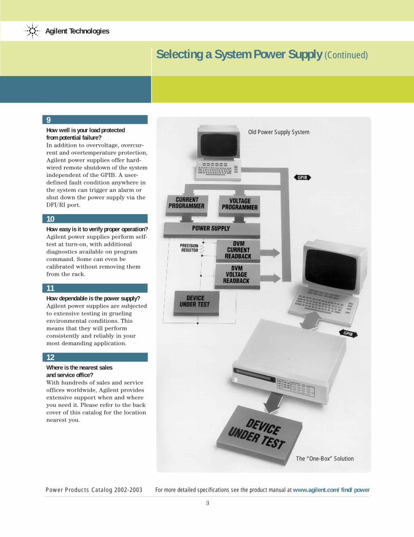
4 How long does it take to integratethe power supplies into your system?With the Agilent “One-Box” Solution,current and voltage programmers,current shunt, and DVM are all partof the single power supply package.This not only takes less rack space,but eliminates external cabling andinterconnections between units,greatly increasing ease of integra-tion and reliability.
5 How long will it take to write a program?With Agilent power supplies, youboth program and read back involts and amps; not binary, percentof full scale, or some other indirectrepresentation. Most Agilent powersupplies use the industry standardprogramming language, SCPI(Standard Commands forProgrammable Instruments). Oncethese commands are learned for oneinstrument, programming anyinstrument is easy.
6Can you find the information you need in the manual?Complete programming, operating,and service documentation isavailable for each Agilent powersupply.
7Is the power supply flexible enoughto meet your changing needs?Agilent offers many choices for system configuration. These includea mainframe with easily removablemodules, full-featured single-outputpower supplies, and preconfiguredmultiple-output power supplies.Power supply outputs can be connected in series and parallel tofurther increase product flexibility.These GPIB power supplies can alsobe controlled without a computerconnected for easy system testingand troubleshooting.
8Will you need additional GPIB interfaces?Agilent multiple-output power supplies and modular powersystems both use one GPIB addressper mainframe. Most Agilentpower supplies also are equippedwith Agilent’s serial link. Thisallows up to 16 power supply out-puts to be programmed from oneGPIB address.
Agilent Technologies
Power Products Catalog 2002-2003 For more detailed specifications see the product manual at www.agilent.com/find/power
2
12 Factors to Consider when
Selecting a System Power Supply
Selecting a System Power Supply
3
Selecting a System Power Supply (Continued)
Power Products Catalog 2002-2003 For more detailed specifications see the product manual at www.agilent.com/find/power
Agilent Technologies
9How well is your load protected from potential failure?In addition to overvoltage, overcur-rent and overtemperature protection,Agilent power supplies offer hard-wired remote shutdown of the systemindependent of the GPIB. A user-defined fault condition anywhere inthe system can trigger an alarm orshut down the power supply via theDFI/RI port.
10How easy is it to verify proper operation?Agilent power supplies perform self-test at turn-on, with additionaldiagnostics available on programcommand. Some can even becalibrated without removing themfrom the rack.
11How dependable is the power supply?Agilent power supplies are subjectedto extensive testing in gruelingenvironmental conditions. Thismeans that they will performconsistently and reliably in yourmost demanding application.
12Where is the nearest sales and service office?With hundreds of sales and serviceoffices worldwide, Agilent providesextensive support when and whereyou need it. Please refer to the backcover of this catalog for the locationnearest you.
Old Power Supply System
The “One-Box” Solution
Agilent Technologies
Power Products Catalog 2002-2003 For more detailed specifications see the product manual at www.agilent.com/find/power
4
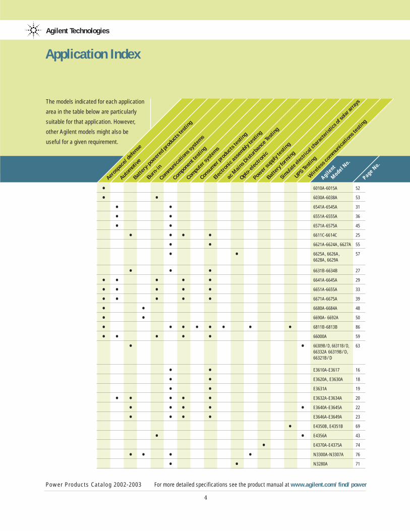
Application Index
The models indicated for each application
area in the table below are particularly
suitable for that application. However,
other Agilent models might also be
useful for a given requirement.
Aerospace/defe
nse
Autom
otive
Battery
-pow
ered pro
ducts te
sting
Burn-in
Comm
unicatio
ns system
s
Component t
esting
Compute
r syste
ms
Consumer p
roducts
testin
g
Electro
nic assem
bly te
sting
ac Main
s Dis
turb
ance Testin
g
Opto-e
lectro
nic
Power s
upply te
sting
Battery
form
ing
Simulate
electrical c
haracte
ristic
s of solar a
rrays
UPS Testin
g
Wire
less com
munic
ations te
sting
• 6010A-6015A 52
• • 6030A-6038A 53
• • 6541A-6545A 31
• • 6551A-6555A 36
• • 6571A-6575A 45
• • • • 6611C-6614C 25
• • 6621A-6624A, 6627A 55
• • 6625A, 6626A, 576628A, 6629A
• • • 6631B-6634B 27
• • • • • 6641A-6645A 29
• • • • • 6651A-6655A 33
• • • • • 6671A-6675A 39
• • 6680A-6684A 48
• • 6690A- 6692A 50
• • • • • • • • 6811B-6813B 86
• • • • • 66000A 59
• • 66309B/D, 66311B/D, 6366332A 66319B/D, 66321B/D
• • E3610A-E3617 16
• • E3620A, E3630A 18
• • E3631A 19
• • • • • E3632A-E3634A 20
• • • • • E3640A-E3645A 22
• • • • E3646A-E3649A 23
• E4350B, E4351B 69
• • E4356A 43
• E4370A-E4375A 74
• • • • N3300A-N3307A 76
• • N3280A 71
Agil
ent
Model N
o.
Page No.
Agilent Technologies
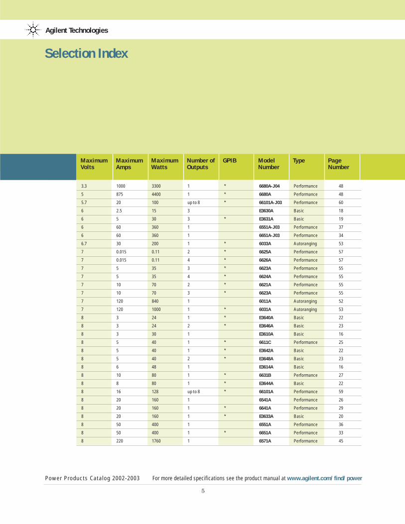
Maximum Maximum Maximum Number of GPIB Model Type PageVolts Amps Watts Outputs Number Number
Power Products Catalog 2002-2003 For more detailed specifications see the product manual at www.agilent.com/find/power
5
Selection Index
3.3 1000 3300 1 * 6680A-J04 Performance 48
5 875 4400 1 * 6680A Performance 48
5.7 20 100 up to 8 * 66101A-J03 Performance 60
6 2.5 15 3 E3630A Basic 18
6 5 30 3 * E3631A Basic 19
6 60 360 1 6551A-J03 Performance 37
6 60 360 1 6651A-J03 Performance 34
6.7 30 200 1 * 6033A Autoranging 53
7 0.015 0.11 2 * 6625A Performance 57
7 0.015 0.11 4 * 6626A Performance 57
7 5 35 3 * 6623A Performance 55
7 5 35 4 * 6624A Performance 55
7 10 70 2 * 6621A Performance 55
7 10 70 3 * 6623A Performance 55
7 120 840 1 6011A Autoranging 52
7 120 1000 1 * 6031A Autoranging 53
8 3 24 1 * E3640A Basic 22
8 3 24 2 * E3646A Basic 23
8 3 30 1 E3610A Basic 16
8 5 40 1 * 6611C Performance 25
8 5 40 1 * E3642A Basic 22
8 5 40 2 * E3648A Basic 23
8 6 48 1 E3614A Basic 16
8 10 80 1 * 6631B Performance 27
8 8 80 1 * E3644A Basic 22
8 16 128 up to 8 * 66101A Performance 59
8 20 160 1 6541A Performance 26
8 20 160 1 * 6641A Performance 29
8 20 160 1 * E3633A Basic 20
8 50 400 1 6551A Performance 36
8 50 400 1 * 6651A Performance 33
8 220 1760 1 6571A Performance 45
6
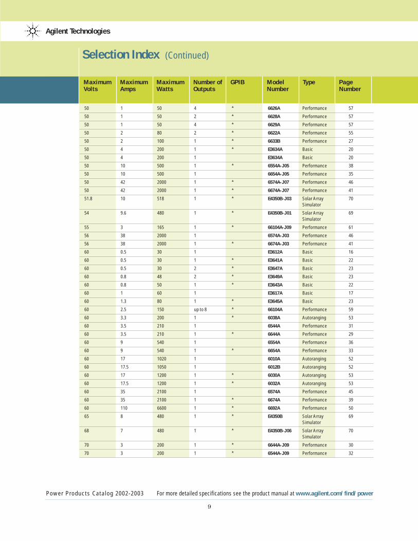
Selection Index (Continued)
Power Products Catalog 2002-2003 For more detailed specifications see the product manual at www.agilent.com/find/power
Agilent Technologies
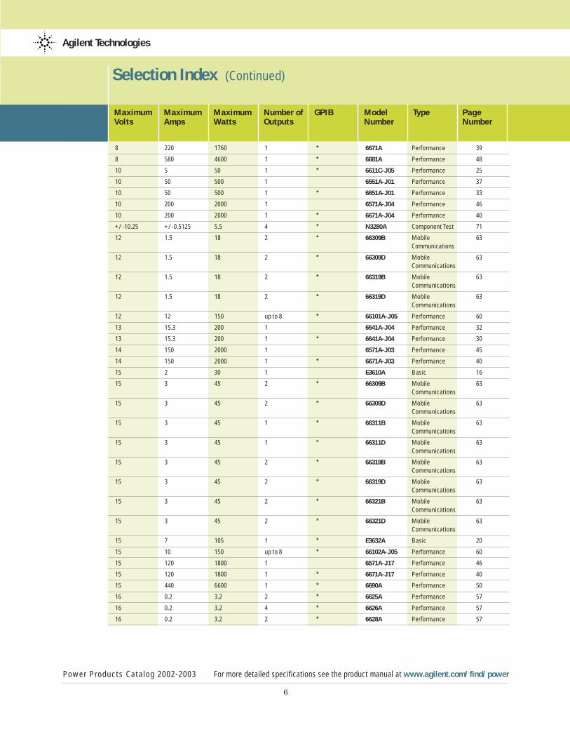
Maximum Maximum Maximum Number of GPIB Model Type PageVolts Amps Watts Outputs Number Number
8 220 1760 1 * 6671A Performance 39
8 580 4600 1 * 6681A Performance 48
10 5 50 1 * 6611C-J05 Performance 25
10 50 500 1 6551A-J01 Performance 37
10 50 500 1 * 6651A-J01 Performance 33
10 200 2000 1 6571A-J04 Performance 46
10 200 2000 1 * 6671A-J04 Performance 40
+/-10.25 +/-0.5125 5.5 4 * N3280A Component Test 71
12 1.5 18 2 * 66309B Mobile 63Communications
12 1.5 18 2 * 66309D Mobile 63 Communications
12 1.5 18 2 * 66319B Mobile 63Communications
12 1.5 18 2 * 66319D Mobile 63Communications
12 12 150 up to 8 * 66101A-J05 Performance 60
13 15.3 200 1 6541A-J04 Performance 32
13 15.3 200 1 * 6641A-J04 Performance 30
14 150 2000 1 6571A-J03 Performance 45
14 150 2000 1 * 6671A-J03 Performance 40
15 2 30 1 E3610A Basic 16
15 3 45 2 * 66309B Mobile 63Communications
15 3 45 2 * 66309D Mobile 63Communications
15 3 45 1 * 66311B Mobile 63Communications
15 3 45 1 * 66311D Mobile 63Communications
15 3 45 2 * 66319B Mobile 63Communications
15 3 45 2 * 66319D Mobile 63Communications
15 3 45 2 * 66321B Mobile 63Communications
15 3 45 2 * 66321D Mobile 63Communications
15 7 105 1 * E3632A Basic 20
15 10 150 up to 8 * 66102A-J05 Performance 60
15 120 1800 1 6571A-J17 Performance 46
15 120 1800 1 * 6671A-J17 Performance 40
15 440 6600 1 * 6690A Performance 50
16 0.2 3.2 2 * 6625A Performance 57
16 0.2 3.2 4 * 6626A Performance 57
16 0.2 3.2 2 * 6628A Performance 57
7
Selection Index (Continued)
Power Products Catalog 2002-2003 For more detailed specifications see the product manual at www.agilent.com/find/power
Agilent Technologies
Maximum Maximum Maximum Number of GPIB Model Type PageVolts Amps Watts Outputs Number Number
16 0.2 3.2 4 * 6629A Performance 57
17 30 510 1 * 6651A-J09 Performance 34
20 0.5 10 3 E3630A Basic 18
20 1.5 30 1 E3611A Basic 16
20 1.5 30 1 * E3640A Basic 22
20 1.5 30 2 * E3646A Basic 23
20 2 40 1 * 6612C Performance 25
20 2 40 3 * 6623A Performance 55
20 2 40 4 * 6624A Performance 55
20 2 40 4 * 6627A Performance 55
20 2.5 50 1 * E3642A Basic 22
20 2.5 50 2 * E3648A Basic 23
20 3 60 1 E3615A Basic 17
20 4 80 2 * 6621A Performance 55
20 4 80 2 * 6622A Performance 55
20 4 80 3 * 6623A Performance 55
20 4 80 1 * E3644A Basic 22
20 5 100 1 * 6632B Performance 27
20 5 100 1 * 66332A Mobile 63Communications
20 7.5 150 up to 8 * 66102A Performance 59
20 10 200 1 * 6033A Autoranging 53
20 10 200 1 * 6038A Autoranging 53
20 10 200 1 6542A Performance 31
20 10 200 1 * 6642A Performance 29
20 10 200 1 * E3633A Basic 20
20 15 300 1 * 6651A-J09 Performance 34
20 25 500 1 6552A Performance 36
20 25 500 1 * 6652A Performance 33
20 50 1000 1 6011A Autoranging 52
20 50 1000 1 6012B Autoranging 52
20 50 1000 1 * 6031A Autoranging 53
20 50 1000 1 * 6032A Autoranging 53
20 100 2000 1 6572A Performance 45
20 100 2000 1 * 6672A Performance 39
21 240 5000 1 * 6682A Performance 48
24 6 100 up to 8 * 66103A-J12 Performance 61
24 85 2000 1 * 6672A-J04 Performance 40
25 1 25 2 E3620A Basic 18
25 1 25 3 * E3631A Basic 19
25 7 160 1 * E3634A Basic 20
25 7 175 1 * E3634A Basic 20
27 20 540 1 * 6652A-J03 Performance 34
8
Selection Index (Continued)
Power Products Catalog 2002-2003 For more detailed specifications see the product manual at www.agilent.com/find/power
Agilent Technologies
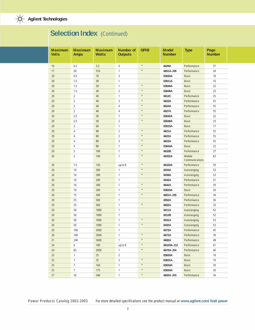
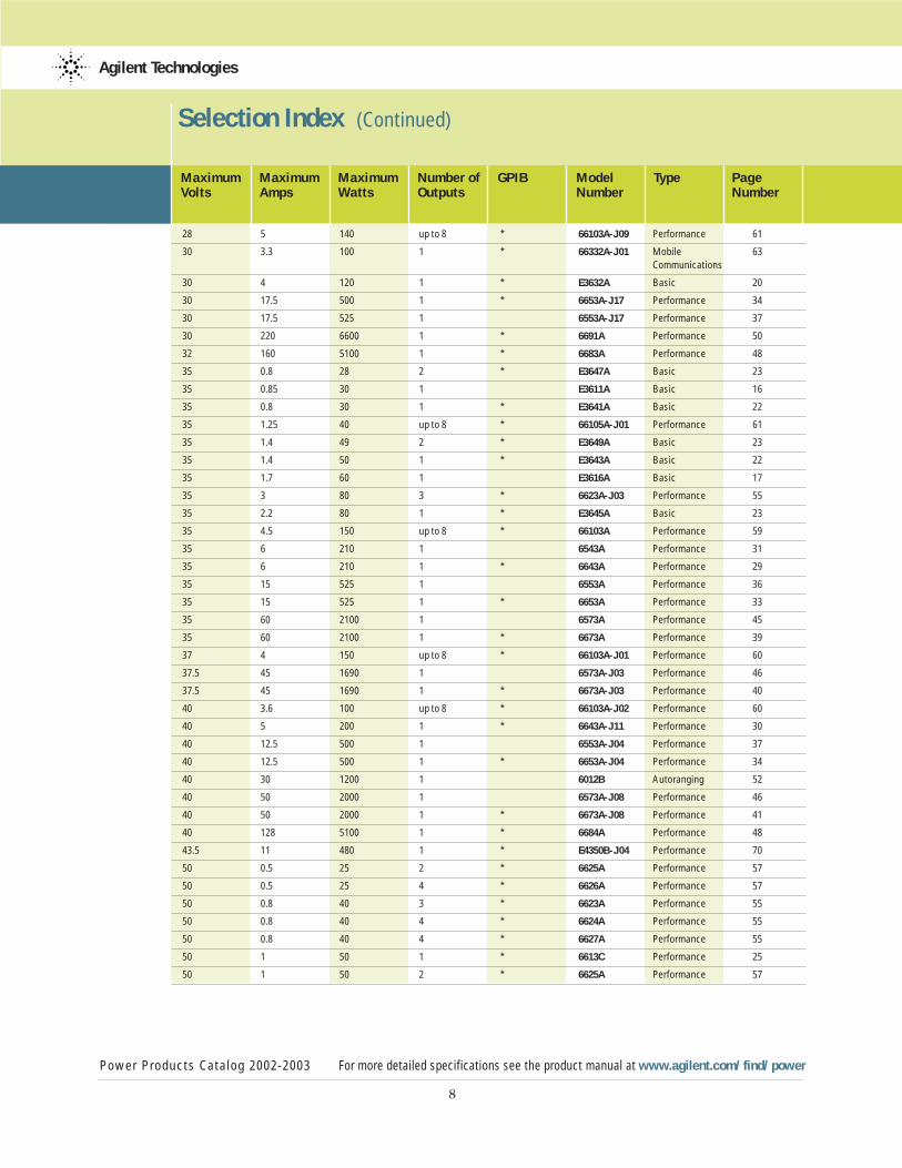
Maximum Maximum Maximum Number of GPIB Model Type PageVolts Amps Watts Outputs Number Number
28 5 140 up to 8 * 66103A-J09 Performance 61
30 3.3 100 1 * 66332A-J01 Mobile 63Communications
30 4 120 1 * E3632A Basic 20
30 17.5 500 1 * 6653A-J17 Performance 34
30 17.5 525 1 6553A-J17 Performance 37
30 220 6600 1 * 6691A Performance 50
32 160 5100 1 * 6683A Performance 48
35 0.8 28 2 * E3647A Basic 23
35 0.85 30 1 E3611A Basic 16
35 0.8 30 1 * E3641A Basic 22
35 1.25 40 up to 8 * 66105A-J01 Performance 61
35 1.4 49 2 * E3649A Basic 23
35 1.4 50 1 * E3643A Basic 22
35 1.7 60 1 E3616A Basic 17
35 3 80 3 * 6623A-J03 Performance 55
35 2.2 80 1 * E3645A Basic 23
35 4.5 150 up to 8 * 66103A Performance 59
35 6 210 1 6543A Performance 31
35 6 210 1 * 6643A Performance 29
35 15 525 1 6553A Performance 36
35 15 525 1 * 6653A Performance 33
35 60 2100 1 6573A Performance 45
35 60 2100 1 * 6673A Performance 39
37 4 150 up to 8 * 66103A-J01 Performance 60
37.5 45 1690 1 6573A-J03 Performance 46
37.5 45 1690 1 * 6673A-J03 Performance 40
40 3.6 100 up to 8 * 66103A-J02 Performance 60
40 5 200 1 * 6643A-J11 Performance 30
40 12.5 500 1 6553A-J04 Performance 37
40 12.5 500 1 * 6653A-J04 Performance 34
40 30 1200 1 6012B Autoranging 52
40 50 2000 1 6573A-J08 Performance 46
40 50 2000 1 * 6673A-J08 Performance 41
40 128 5100 1 * 6684A Performance 48
43.5 11 480 1 * E4350B-J04 Performance 70
50 0.5 25 2 * 6625A Performance 57
50 0.5 25 4 * 6626A Performance 57
50 0.8 40 3 * 6623A Performance 55
50 0.8 40 4 * 6624A Performance 55
50 0.8 40 4 * 6627A Performance 55
50 1 50 1 * 6613C Performance 25
50 1 50 2 * 6625A Performance 57
9
Selection Index (Continued)
Power Products Catalog 2002-2003 For more detailed specifications see the product manual at www.agilent.com/find/power
Agilent Technologies
Maximum Maximum Maximum Number of GPIB Model Type PageVolts Amps Watts Outputs Number Number
50 1 50 4 * 6626A Performance 57
50 1 50 2 * 6628A Performance 57
50 1 50 4 * 6629A Performance 57
50 2 80 2 * 6622A Performance 55
50 2 100 1 * 6633B Performance 27
50 4 200 1 * E3634A Basic 20
50 4 200 1 E3634A Basic 20
50 10 500 1 * 6554A-J05 Performance 38
50 10 500 1 6654A-J05 Performance 35
50 42 2000 1 * 6574A-J07 Performance 46
50 42 2000 1 * 6674A-J07 Performance 41
51.8 10 518 1 * E4350B-J03 Solar Array 70Simulator
54 9.6 480 1 * E4350B-J01 Solar Array 69Simulator
55 3 165 1 * 66104A-J09 Performance 61
56 38 2000 1 6574A-J03 Performance 46
56 38 2000 1 * 6674A-J03 Performance 41
60 0.5 30 1 E3612A Basic 16
60 0.5 30 1 * E3641A Basic 22
60 0.5 30 2 * E3647A Basic 23
60 0.8 48 2 * E3649A Basic 23
60 0.8 50 1 * E3643A Basic 22
60 1 60 1 E3617A Basic 17
60 1.3 80 1 * E3645A Basic 23
60 2.5 150 up to 8 * 66104A Performance 59
60 3.3 200 1 * 6038A Autoranging 53
60 3.5 210 1 6544A Performance 31
60 3.5 210 1 * 6644A Performance 29
60 9 540 1 6554A Performance 36
60 9 540 1 * 6654A Performance 33
60 17 1020 1 6010A Autoranging 52
60 17.5 1050 1 6012B Autoranging 52
60 17 1200 1 * 6030A Autoranging 53
60 17.5 1200 1 * 6032A Autoranging 53
60 35 2100 1 6574A Performance 45
60 35 2100 1 * 6674A Performance 39
60 110 6600 1 * 6692A Performance 50
65 8 480 1 * E4350B Solar Array 69Simulator
68 7 480 1 * E4350B-J06 Solar Array 70Simulator
70 3 200 1 * 6644A-J09 Performance 30
70 3 200 1 * 6544A-J09 Performance 32
10
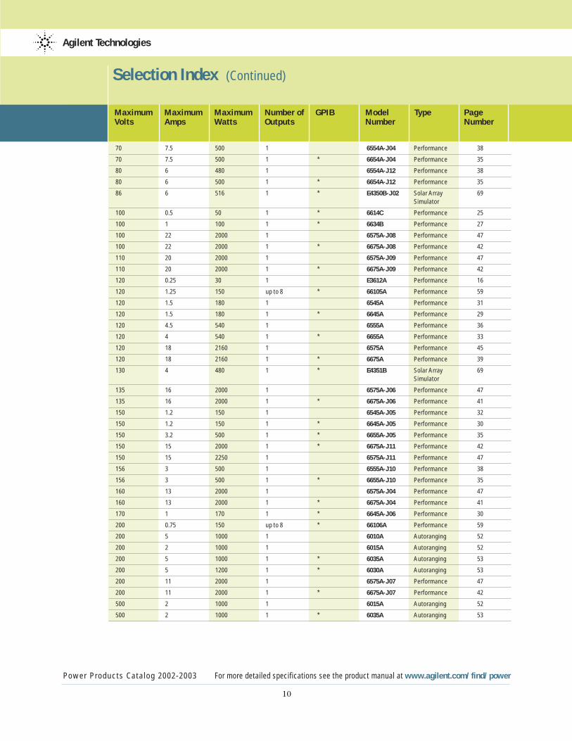
Selection Index (Continued)
Power Products Catalog 2002-2003 For more detailed specifications see the product manual at www.agilent.com/find/power
Agilent Technologies
Maximum Maximum Maximum Number of GPIB Model Type PageVolts Amps Watts Outputs Number Number
70 7.5 500 1 6554A-J04 Performance 38
70 7.5 500 1 * 6654A-J04 Performance 35
80 6 480 1 6554A-J12 Performance 38
80 6 500 1 * 6654A-J12 Performance 35
86 6 516 1 * E4350B-J02 Solar Array 69Simulator
100 0.5 50 1 * 6614C Performance 25
100 1 100 1 * 6634B Performance 27
100 22 2000 1 6575A-J08 Performance 47
100 22 2000 1 * 6675A-J08 Performance 42
110 20 2000 1 6575A-J09 Performance 47
110 20 2000 1 * 6675A-J09 Performance 42
120 0.25 30 1 E3612A Performance 16
120 1.25 150 up to 8 * 66105A Performance 59
120 1.5 180 1 6545A Performance 31
120 1.5 180 1 * 6645A Performance 29
120 4.5 540 1 6555A Performance 36
120 4 540 1 * 6655A Performance 33
120 18 2160 1 6575A Performance 45
120 18 2160 1 * 6675A Performance 39
130 4 480 1 * E4351B Solar Array 69Simulator
135 16 2000 1 6575A-J06 Performance 47
135 16 2000 1 * 6675A-J06 Performance 41
150 1.2 150 1 6545A-J05 Performance 32
150 1.2 150 1 * 6645A-J05 Performance 30
150 3.2 500 1 * 6655A-J05 Performance 35
150 15 2000 1 * 6675A-J11 Performance 42
150 15 2250 1 6575A-J11 Performance 47
156 3 500 1 6555A-J10 Performance 38
156 3 500 1 * 6655A-J10 Performance 35
160 13 2000 1 6575A-J04 Performance 47
160 13 2000 1 * 6675A-J04 Performance 41
170 1 170 1 * 6645A-J06 Performance 30
200 0.75 150 up to 8 * 66106A Performance 59
200 5 1000 1 6010A Autoranging 52
200 2 1000 1 6015A Autoranging 52
200 5 1000 1 * 6035A Autoranging 53
200 5 1200 1 * 6030A Autoranging 53
200 11 2000 1 6575A-J07 Performance 47
200 11 2000 1 * 6675A-J07 Performance 42
500 2 1000 1 6015A Autoranging 52
500 2 1000 1 * 6035A Autoranging 53
6030 Series
Autora
ngers
6610 & 6630 Serie
s Sin
gle-Outp
ut
6620 Series
Multi
ple-Outp
ut
6620 Series
Precisi
on Multi
ple-Outp
ut
6640 & 6650 Serie
s Sin
gle-Outp
ut
6670-6690 Serie
s Sin
gle-Outp
ut
66000 Modula
r Power S
yste
ms
66300 Series
Mobile
Communications
E3630 & E3640 Series S
ingle & Multip
le-Output
N3280A Pre
cision M
ultiple-O
utput
Agilent Technologies
Power Products Catalog 2002-2003 For more detailed specifications see the product manual at www.agilent.com/find/power
11
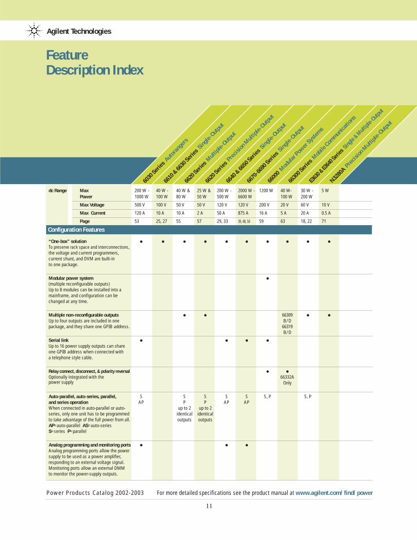
Feature Description Index
dc Range Max 200 W - 40 W - 40 W & 25 W & 200 W - 2000 W - 1200 W 40 W- 30 W - 5 W Power 1000 W 100 W 80 W 50 W 500 W 6600 W 100 W 200 W
Max Voltage 500 V 100 V 50 V 50 V 120 V 120 V 200 V 20 V 60 V 10 V
Max Current 120 A 10 A 10 A 2 A 50 A 875 A 16 A 5 A 20 A 0.5 A
Page 53 25, 27 55 57 29, 33 39, 48, 50 59 63 18, 22 71
Configuration Features
“One-box” solution • • • • • • • • • •To preserve rack space and interconnections, the voltage and current programmers, current shunt, and DVM are built-in to one package.
Modular power system •(multiple reconfigurable outputs)Up to 8 modules can be installed into a mainframe, and configuration can be changed at any time.
Multiple non-reconfigurable outputs • • 66309 • •Up to four outputs are included in one B/Dpackage, and they share one GPIB address. 66319
B/D
Serial link • • • •Up to 16 power supply outputs can share one GPIB address when connected with a telephone style cable.
Relay connect, disconnect, & polarity reversal• • •Optionally integrated with the 66332Apower supply Only
Auto-parallel, auto-series, parallel, • S S S S S S, P S, Pand series operation AP P P AP APWhen connected in auto-parallel or auto- up to 2 up to 2series, only one unit has to be programmed identical identicalto take advantage of the full power from all. outputs outputs AP=auto-parallel AS=auto-series S=series P=parallel
Analog programming and monitoring ports• • • •Analog programming ports allow the power supply to be used as a power amplifier, responding to an external voltage signal. Monitoring ports allow an external DMM to monitor the power-supply outputs.
Agilent Technologies
Feature Description Index (Continued)
6030 Series
Autora
ngers
6610 & 6630 Serie
s Sin
gle-Outp
ut
6620 Series
Multi
ple-Outp
ut
6620 Series
Precisi
on Multi
ple-Outp
ut
6640 & 6650 Serie
s Sin
gle-Outp
ut
6670-6690 Serie
s Sin
gle-Outp
ut
66000 Modula
r Power S
yste
ms
66300 Series
Mobile
Communications
E3630 & E3640 Series S
ingle & Multip
le-Output
N3280A Pre
cision M
ultiple-O
utput
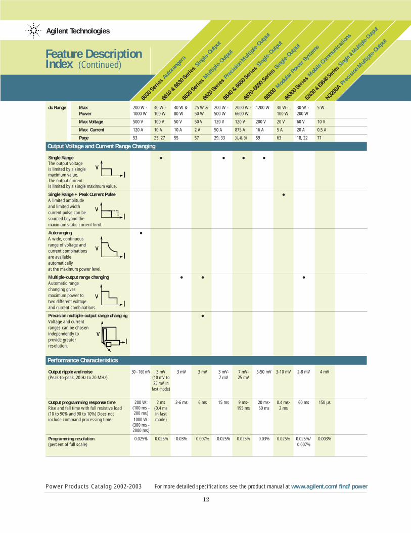
dc Range Max 200 W - 40 W - 40 W & 25 W & 200 W - 2000 W - 1200 W 40 W- 30 W - 5 W Power 1000 W 100 W 80 W 50 W 500 W 6600 W 100 W 200 W
Max Voltage 500 V 100 V 50 V 50 V 120 V 120 V 200 V 20 V 60 V 10 V
Max Current 120 A 10 A 10 A 2 A 50 A 875 A 16 A 5 A 20 A 0.5 A
Page 53 25, 27 55 57 29, 33 39, 48, 50 59 63 18, 22 71
Output Voltage and Current Range Changing
Single Range • • • •The output voltage is limited by a single maximum value. The output current is limited by a single maximum value.
Single Range + Peak Current Pulse •A limited amplitude and limited width current pulse can be sourced beyond the maximum static current limit.
Autoranging •A wide, continuous range of voltage and current combinationsare available automatically at the maximum power level.
Multiple-output range changing • • •Automatic range changing gives maximum power to two different voltage and current combinations.
Precision multiple-output range changing •Voltage and current ranges can be chosen independently to provide greater resolution.
Performance Characteristics
Output ripple and noise 30 - 160 mV 3 mV 3 mV 3 mV 3 mV- 7 mV- 5-50 mV 3-10 mV 2-8 mV 4 mV(Peak-to-peak, 20 Hz to 20 MHz) (10 mV to 7 mV 25 mV
25 mV infast mode)
Output programming response time • 200 W: 2 ms 2-6 ms 6 ms 15 ms 9 ms- 20 ms- 0.4 ms- 60 ms 150 µsRise and fall time with full resistive load (100 ms - (0.4 ms 195 ms 50 ms 2 ms(10 to 90% and 90 to 10%) Does not 200 ms) in fast include command processing time. 1000 W: mode)
(300 ms -2000 ms)
Programming resolution • 0.025% 0.025% 0.03% 0.007% 0.025% 0.025% 0.03% 0.025% 0.025%/ 0.003% (percent of full scale) 0.007%
Power Products Catalog 2002-2003 For more detailed specifications see the product manual at www.agilent.com/find/power
12
vl
vl
vl
vl
vl
Agilent Technologies
Feature Description Index (Continued)
6030 Series
Autora
ngers
6610 & 6630 Serie
s Sin
gle-Outp
ut
6620 Series
Multi
ple-Outp
ut
6620 Series
Precisi
on Multi
ple-Outp
ut
6640 & 6650 Serie
s Sin
gle-Outp
ut
6670-6690 Serie
s Sin
gle-Outp
ut
66000 Modula
r Power S
yste
ms
66300 Series
Mobile
Communications
E3630 & E3640 Series S
ingle & Multip
le-Output
N3280A Pre
cision M
ultiple-O
utput
Power Products Catalog 2002-2003 For more detailed specifications see the product manual at www.agilent.com/find/power
13
dc Range Max 200 W - 40 W - 40 W & 25 W & 200 W - 2000 W - 1200 W 40 W- 30 W - 5 W Power 1000 W 100 W 80 W 50 W 500 W 6600 W 100 W 200 W
Max Voltage 500 V 100 V 50 V 50 V 120 V 120 V 200 V 20 V 60 V 10 V
Max Current 120 A 10 A 10 A 2 A 50 A 875 A 16 A 5 A 20 A 0.5 A
Page 53 25, 27 55 57 29, 33 39, 48, 50 59 63 18, 22 71
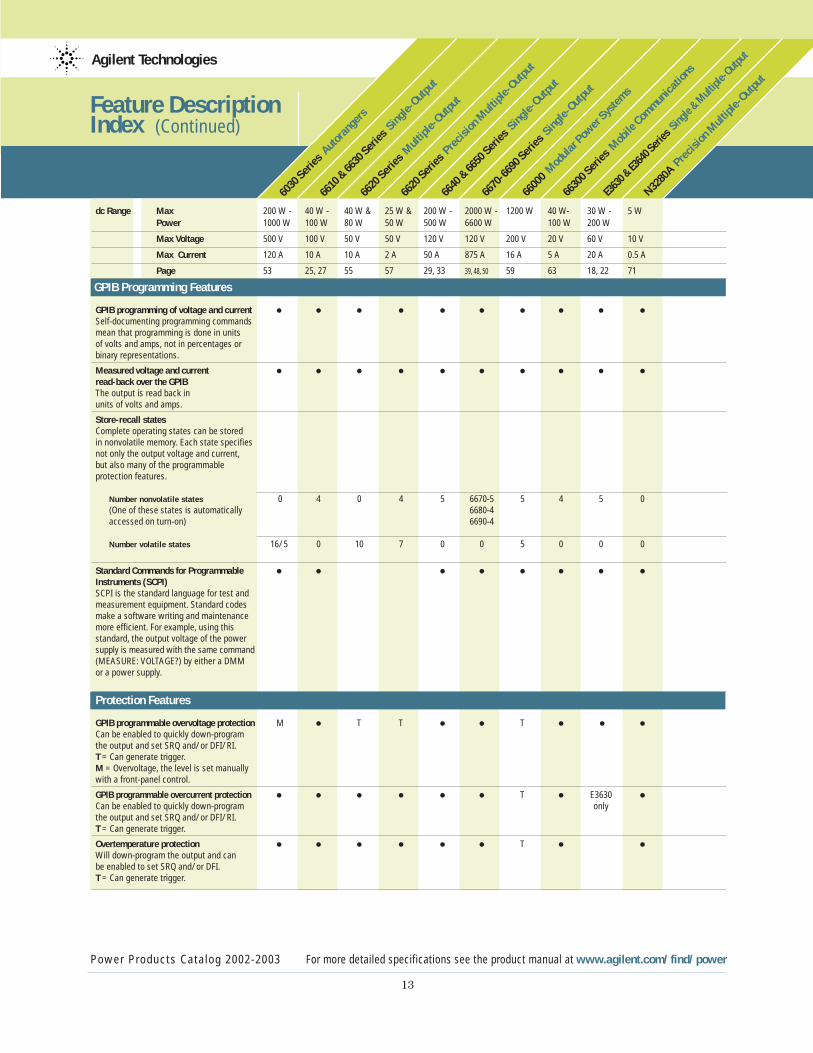
GPIB Programming Features
GPIB programming of voltage and current • • • • • • • • • •Self-documenting programming commands mean that programming is done in units of volts and amps, not in percentages or binary representations.
Measured voltage and current • • • • • • • • • •read-back over the GPIBThe output is read back in units of volts and amps.
Store-recall states •Complete operating states can be stored in nonvolatile memory. Each state specifies not only the output voltage and current, but also many of the programmable protection features.
Number nonvolatile states 0 4 0 4 5 6670-5 5 4 5 0 (One of these states is automatically 6680-4accessed on turn-on) 6690-4
Number volatile states 16/5 0 10 7 0 0 5 0 0 0
Standard Commands for Programmable • • • • • • • •Instruments (SCPI)SCPI is the standard language for test and measurement equipment. Standard codesmake a software writing and maintenance more efficient. For example, using this standard, the output voltage of the power supply is measured with the same command(MEASURE: VOLTAGE?) by either a DMM or a power supply.
Protection Features •GPIB programmable overvoltage protection M • T T • • T • • •Can be enabled to quickly down-program the output and set SRQ and/or DFI/RI. T = Can generate trigger.M = Overvoltage, the level is set manually with a front-panel control.
GPIB programmable overcurrent protection • • • • • • T • E3630 •Can be enabled to quickly down-program onlythe output and set SRQ and/or DFI/RI.T = Can generate trigger.
Overtemperature protection • • • • • • T • •Will down-program the output and can be enabled to set SRQ and/or DFI. T = Can generate trigger.

Agilent Technologies
Feature Description Index (Continued)
6030 Series
Autora
ngers
6610 & 6630 Serie
s Sin
gle-Outp
ut
6620 Series
Multi
ple-Outp
ut
6620 Series
Precisi
on Multi
ple-Outp
ut
6640 & 6650 Serie
s Sin
gle-Outp
ut
6670-6690 Serie
s Sin
gle-Outp
ut
66000 Modula
r Power S
yste
ms
66300 Series
Mobile
Communications
E3630 & E3640 Series S
ingle & Multip
le-Output
N3280A Pre
cision M
ultiple-O
utput
Power Products Catalog 2002-2003 For more detailed specifications see the product manual at www.agilent.com/find/power
14
dc Range Max 200 W - 40 W - 40 W & 25 W & 200 W - 2000 W - 1200 W 40 W- 30 W - 5 W Power 1000 W 100 W 80 W 50 W 500 W 6600 W 100 W 200 W
Max Voltage 500 V 100 V 50 V 50 V 120 V 120 V 200 V 20 V 60 V 10 V
Max Current 120 A 10 A 10 A 2 A 50 A 875 A 16 A 5 A 20 A 0.5 A
Page 53 25, 27 55 57 29, 33 39, 48, 50 59 63 18, 22 71
Protection Features (Continued)
Discrete fault indicator/ • • O O • • • •remote inhibit (DFI/RI)Using these digital ports, power supplies can be connected independently of the GPIB. If any one experiences an error condition (overvoltage, for example),it can signal the other units to also
downprogram their outputs.O = Optional
SRQ • • • • • • • • •Almost any fault condition or change of state of the power supply can be enabled to generate an SRQ. This signals the computer to take the appropriate action.
Local lockout • • • • • • • • •Front-panel or keyboard control can be disabled. This keepsunauthorized operators from changing the programmed states.
Fan-speed control • • • • • •Controls the fan-speed to provide only the required cooling, reducing unnecessary acoustic noise. O = Optional
Active down-programming • P 6610-P F F P P P P Active circuits quickly drain the energy 6630-Ffrom the output when unit is programmed to a lower voltage. This means that a unit under test can be safely removed from its test fixture without danger of arcing.F = Full-rated output currentP = Less than 100% rated output current
Maintenance Features •Electronic calibration in the rack • • • • • • • • •Calibration requires no internal adjustments.
Calibration security • P, S J J P, J P, J P, S P, S P, J P Units can be protected from accidental access to calibration routines by either a password (P) or an internal jumper (J ) or switch (s).
Self-test • • • • • • • • • •Extensive self-test is triggered automatically on power-up. Additional tests can be initialed by user programming or front-panel control.
*A nonvolatile status in SCPI mode only.
Power Products Catalog 2002-2003 www.agilent.com/find/power
15
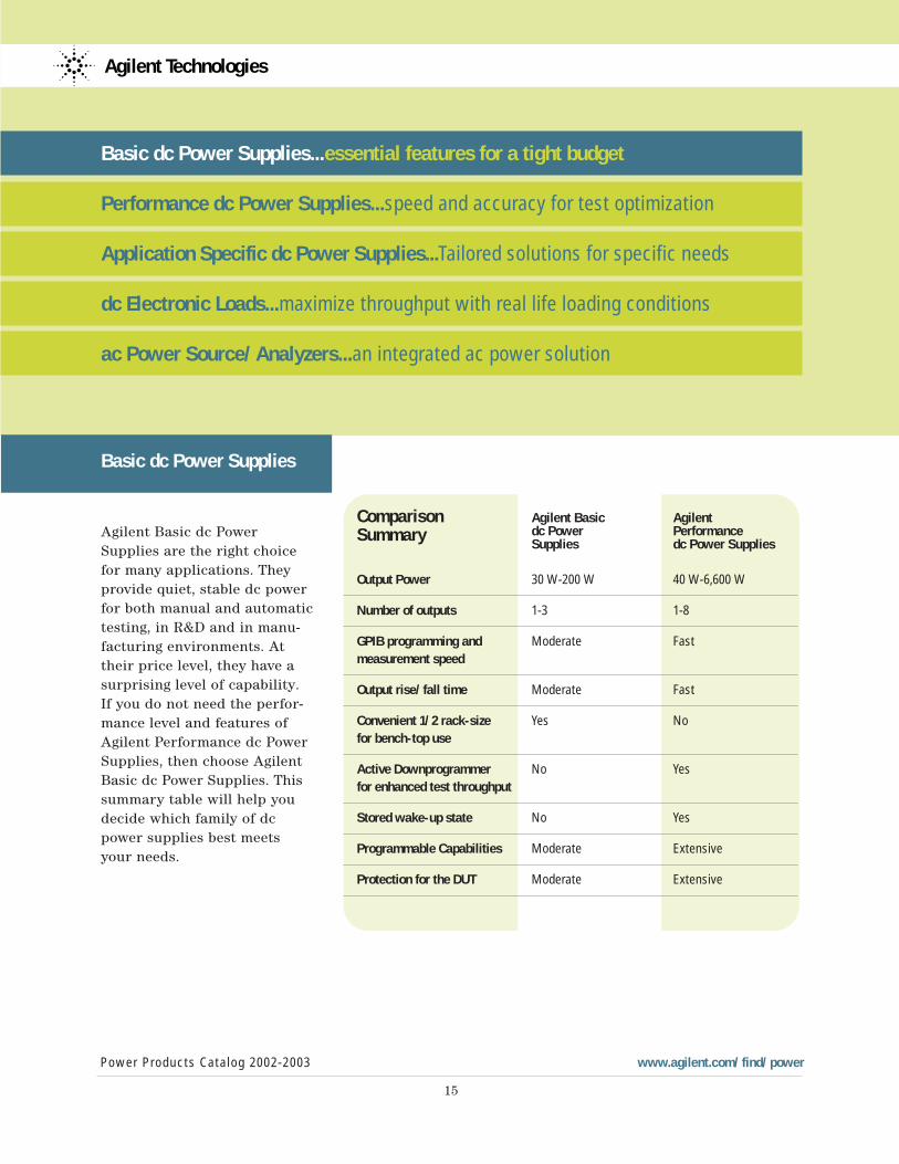
Comparison Agilent Basic Agilent
Summary dc Power Performance Supplies dc Power Supplies
Output Power 30 W-200 W 40 W-6,600 W
Number of outputs 1-3 1-8
GPIB programming and Moderate Fastmeasurement speed
Output rise/fall time Moderate Fast
Convenient 1/2 rack-size Yes No for bench-top use
Active Downprogrammer No Yesfor enhanced test throughput
Stored wake-up state No Yes
Programmable Capabilities Moderate Extensive
Protection for the DUT Moderate Extensive
Agilent Technologies
Basic dc Power Supplies...essential features for a tight budget
Performance dc Power Supplies...speed and accuracy for test optimization
Application Specific dc Power Supplies...Tailored solutions for specific needs
dc Electronic Loads...maximize throughput with real life loading conditions
ac Power Source/Analyzers...an integrated ac power solution
Basic dc Power Supplies
Agilent Basic dc PowerSupplies are the right choicefor many applications. Theyprovide quiet, stable dc powerfor both manual and automatictesting, in R&D and in manu-facturing environments. Attheir price level, they have asurprising level of capability.If you do not need the perfor-mance level and features ofAgilent Performance dc PowerSupplies, then choose AgilentBasic dc Power Supplies. Thissummary table will help youdecide which family of dcpower supplies best meetsyour needs.
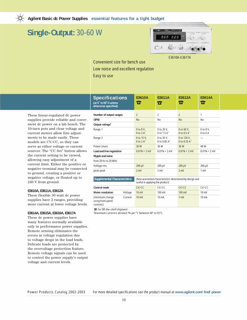
These linear-regulated dc powersupplies provide reliable and conve-nient dc power on a lab bench. The10-turn pots and clear voltage andcurrent meters allow fine adjust-ments to be made easily. These models are CV/CC, so they can serve as either voltage or currentsources. The “CC Set” button allowsthe current setting to be viewed,allowing easy adjustment of a current limit. Either the positive ornegative terminal may be connectedto ground, creating a positive ornegative voltage, or floated up to240 V from ground.
E3610A, E3611A, E3612AThese flexible 30 watt dc power supplies have 2 ranges, providingmore current at lower voltage levels.
E3614A, E3615A, E3616A, E3617AThese dc power supplies have many features normally availableonly in performance power supplies.Remote sensing eliminates theerrors in voltage regulation due to voltage drops in the load leads.Delicate loads are protected by the overvoltage protection feature.Remote voltage signals can be usedto control the power supply’s outputvoltage and current levels.
Agilent Basic dc Power Supplies essential features for a tight budget
Specif ications(at 0˚ to 55˚C unless otherwise specified)
Power Products Catalog 2002-2003 For more detailed specifications see the product manual at www.agilent.com/find/power
16
Convenient size for bench use
Low noise and excellent regulation
Easy to use
E3610A-E3617A
Single-Output: 30-60 W
E3610A E3611A E3612A E3614A
Number of output ranges 2 2 2 1
GPIB No No No No
Output ratings1
Range 1 0 to 8 V, 0 to 20 V, 0 to 60 V, 0 to 8 V, 0 to 3 A1 0 to 1.5 A1 0 to 0.5 A1 0 to 6 A
Range 2 0 to 15 V, 0 to 35 V, 0 to 120 V, — 0 to 2 A1 0 to 0.85 A1 0 to 0.25 A1
Power (max) 30 W 30 W 30 W 48 W
Load and line regulation 0.01% + 2 mV 0.01% + 2 mV 0.01% + 2 mV 0.01% + 2 mV
Ripple and noise
from 20 Hz to 20 MHz
Voltage rms 200 µV 200 µV 200 µV 200 µV
peak-peak 2 mV 2 mV 2 mV 1 mV
Supplemental Characteristics (Non-warranted characteristics determined by design and useful in applying the product)
Control mode CV/CC CV/CC CV/CC CV/CC
Meter resolution Voltage 10 mV 100 mV 100 mV 10 mV
(minimum change Current 10 mA 10 mA 1 mA 10 mAusing front-panelcontrols)
For 0ff-the-shelf shipment1Maximum current is derated 1% per °C between 40° to 55°C.
17
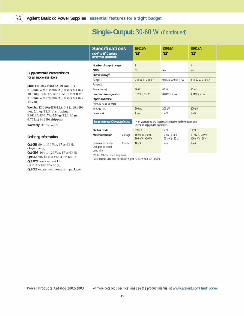
Supplemental Characteristicsfor all model numbers
Size: E3610A-E3612A: 91 mm H x 213 mm W x 319 mm D (3.6 in x 8.4 in x12.6 in); E3614A-E3617A: 91 mm H x 213 mm W x 373 mm D (3.6 in x 8.4 in x14.7 in)
Weight: E3610A-E3612A: 3.8 kg (8.4 lb)net, 5.1 kg (11.3 lb) shipping; E3614A-E3617A: 5.5 kg (12.1 lb) net, 6.75 kg (14.9 lb) shipping
Warranty: Three years.
Ordering Information
Opt 0E9 90 to 110 Vac, 47 to 63 Hz (Japan only)Opt 0EM 104 to 126 Vac, 47 to 63 HzOpt 0E3 207 to 253 Vac, 47 to 63 HzOpt 1CM rack mount kit (E3614A-E3617A only)Opt 0L2 extra documentation package
Single-Output: 30-60 W (Continued)
Specif ications(at 0˚ to 55˚C unless otherwise specified)
Power Products Catalog 2002-2003 For more detailed specifications see the product manual at www.agilent.com/find/power
Agilent Basic dc Power Supplies essential features for a tight budget
Specif ications(at 0˚ to 55˚C unless otherwise specified)
E3615A E3616A E3617A
Number of output ranges 1 1 1
GPIB No No No
Output ratings1
Range 1 0 to 20 V, 0 to 3 A 0 to 35 V, 0 to 1.7 A 0 to 60 V, 0 to 1 A
Range 2 — — —
Power (max) 60 W 60 W 60 W
Load and line regulation 0.01% + 2 mV 0.01% + 2 mV 0.01% + 2 mV
Ripple and noise
from 20 Hz to 20 MHz
Voltage rms 200 µV 200 µV 200 µV
peak-peak 1 mV 1 mV 1 mV
Supplemental Characteristics (Non-warranted characteristics determined by design and useful in applying the product)
Control mode CV/CC CV/CC CV/CC
Meter resolution Voltage 10 mV (0-20 V), 10 mV (0-20 V), 10 mV (0-20 V),100 mV (>20 V) 100 mV (>20 V) 100 mV (>20 V)
(minimum change Current 10 mA 1 mA 1 mA using front-panelcontrols)
For 0ff-the-shelf shipment1Maximum current is derated 1% per °C between 40° to 55°C.
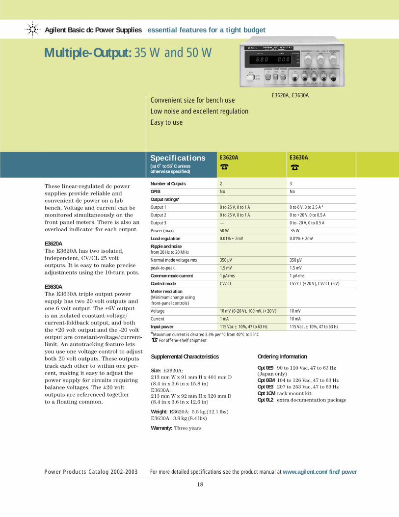
These linear-regulated dc powersupplies provide reliable and convenient dc power on a lab bench. Voltage and current can bemonitored simultaneously on thefront panel meters. There is also an overload indicator for each output.
E3620AThe E3620A has two isolated, independent, CV/CL 25 volt outputs. It is easy to make preciseadjustments using the 10-turn pots.
E3630AThe E3630A triple output powersupply has two 20 volt outputs andone 6 volt output. The +6V output is an isolated constant-voltage/current-foldback output, and boththe +20 volt output and the -20 voltoutput are constant-voltage/current-limit. An autotracking feature letsyou use one voltage control to adjustboth 20 volt outputs. These outputstrack each other to within one per-cent, making it easy to adjust thepower supply for circuits requiringbalance voltages. The ±20 volt outputs are referenced together to a floating common.
Agilent Basic dc Power Supplies essential features for a tight budget
Specif ications(at 0˚ to 55˚C unless otherwise specified)
E3620A E3630A
Power Products Catalog 2002-2003 For more detailed specifications see the product manual at www.agilent.com/find/power
18
Convenient size for bench use
Low noise and excellent regulation
Easy to use
E3620A, E3630A
Multiple-Output: 35 W and 50 W
Number of Outputs 2 3
GPIB No No
Output ratings*
Output 1 0 to 25 V, 0 to 1 A 0 to 6 V, 0 to 2.5 A*
Output 2 0 to 25 V, 0 to 1 A 0 to +20 V, 0 to 0.5 A
Output 3 — 0 to -20 V, 0 to 0.5 A
Power (max) 50 W 35 W
Load regulation 0.01% + 2mV 0.01% + 2mV
Ripple and noisefrom 20 Hz to 20 MHz
Normal mode voltage rms 350 µV 350 µV
peak-to-peak 1.5 mV 1.5 mV
Common mode current 1 µArms 1 µArms
Control mode CV/CL CV/CL (±20 V), CV/CL (6 V)
Meter resolution(Minimum change usingfront-panel controls)
Voltage 10 mV (0-20 V), 100 mV, (>20 V) 10 mV
Current 1 mA 10 mA
Input power 115 Vac ± 10%, 47 to 63 Hz 115 Vac, ± 10%, 47 to 63 Hz
*Maximum current is derated 3.3% per °C from 40°C to 55°C For off-the-shelf shipment
Ordering Information
Opt 0E9 90 to 110 Vac, 47 to 63 Hz (Japan only)Opt 0EM 104 to 126 Vac, 47 to 63 HzOpt 0E3 207 to 253 Vac, 47 to 63 HzOpt 1CM rack mount kit Opt 0L2 extra documentation package
Supplemental Characteristics
Size: E3620A: 213 mm W x 91 mm H x 401 mm D (8.4 in x 3.6 in x 15.8 in) E3630A: 213 mm W x 92 mm H x 320 mm D(8.4 in x 3.6 in x 12.6 in)
Weight: E3620A: 5.5 kg (12.1 lbs)E3630A: 3.8 kg (8.4 lbs)
Warranty: Three years
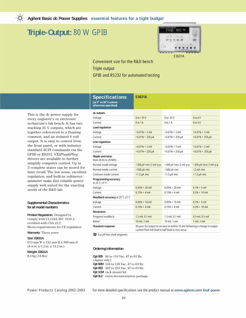
This is the dc power supply forevery engineer’s or electronic technician’s lab bench. It has twotracking 25 V outputs, which aretogether referenced to a floatingcommon, and an isolated 6 volt output. It is easy to control from the front panel, or with industrystandard SCPI commands via theGPIB or RS232. VXIPlug&Playdrivers are available to further simplify computer control. Up to 3 complete states can be stored forlater recall. The low noise, excellentregulation, and built-in voltmeter/ammeter make this reliable powersupply well suited for the exactingneeds of the R&D lab.
Agilent Basic dc Power Supplies essential features for a tight budget
Specif ications(at 0˚ to 55˚C unless otherwise specified)
E3631A
Power Products Catalog 2002-2003 For more detailed specifications see the product manual at www.agilent.com/find/power
19
Convenient size for the R&D bench
Triple output
GPIB and RS232 for automated testing
E3631A
Triple-Output: 80 W GPIB
dc outputs
Voltage 0 to +25 V 0 to -25 V 0 to 6 V
Current 0 to 1 A 0 to 1 A 0 to 5 A
Load regulation
Voltage <0.01% + 2 mV <0.01% + 2 mV <0.01% + 2 mV
Current <0.01% + 250 µA <0.01% + 250 µA <0.01% + 250 µA
Line regulation
Voltage <0.01% + 2 mV <0.01% + 2 mV <0.01% + 2 mV
Current <0.01% + 250 µA <0.01% + 250 µA <0.01% + 250 µA
Ripple and noisefrom 20 Hz to 20 MHz
Normal-mode voltage <350 µV rms/2 mV p-p <350 µV rms/2 mV p-p <350 µV rms/2 mV p-p
Normal-mode current <500 µA rms <500 µA rms <2 mA rms
Common-mode current <1.5 µA rms <1.5 µA rms <1.5 µA rms
Programming accuracy at 25˚C ±5˚C
Voltage 0.05% + 20 mV 0.05% + 20 mV 0.1% + 5 mV
Current 0.15% + 4 mA 0.15% + 4 mA 0.2% + 10 mA
Readback accuracy at 25˚C ±5˚C
Voltage 0.05% + 10 mV 0.05% + 10 mV 0.1% + 5 mV
Current 0.15% + 4 mA 0.15% + 4 mA 0.2% + 10 mA
Resolution
Program/readback 1.5 mV, 0.1 mA 1.5 mV, 0.1 mA 0.5 mV, 0.5 mA
Meter 10 mV, 1 mA 10 mV, 1 mA 1 mV, 1 mA
Transient response 50 µsec for output to recover to within 15 mV following a change in output current from full load to half load or vice versa
For off-the-shelf shipment
Supplemental Characteristicsfor all model numbers
Product Regulation: Designed to comply with UL1244, IEC 1010-1; certified with CSA 22.2Meets requirements for CE regulation
Warranty: Three years
Size: E3631A213 mm W x 132 mm H x 360 mm D(8.4 in. x 5.2 in. x 14.2 in.)
Weight: E3631A8.2 kg (18 lbs)
Ordering Information
Opt 0E9 90 to 110 Vac, 47 to 63 Hz (Japan only)Opt 0EM 104 to 126 Vac, 47 to 63 HzOpt 0E3 207 to 253 Vac, 47 to 63 HzOpt 1CM rack mount kit Opt 0L2 extra documentation package
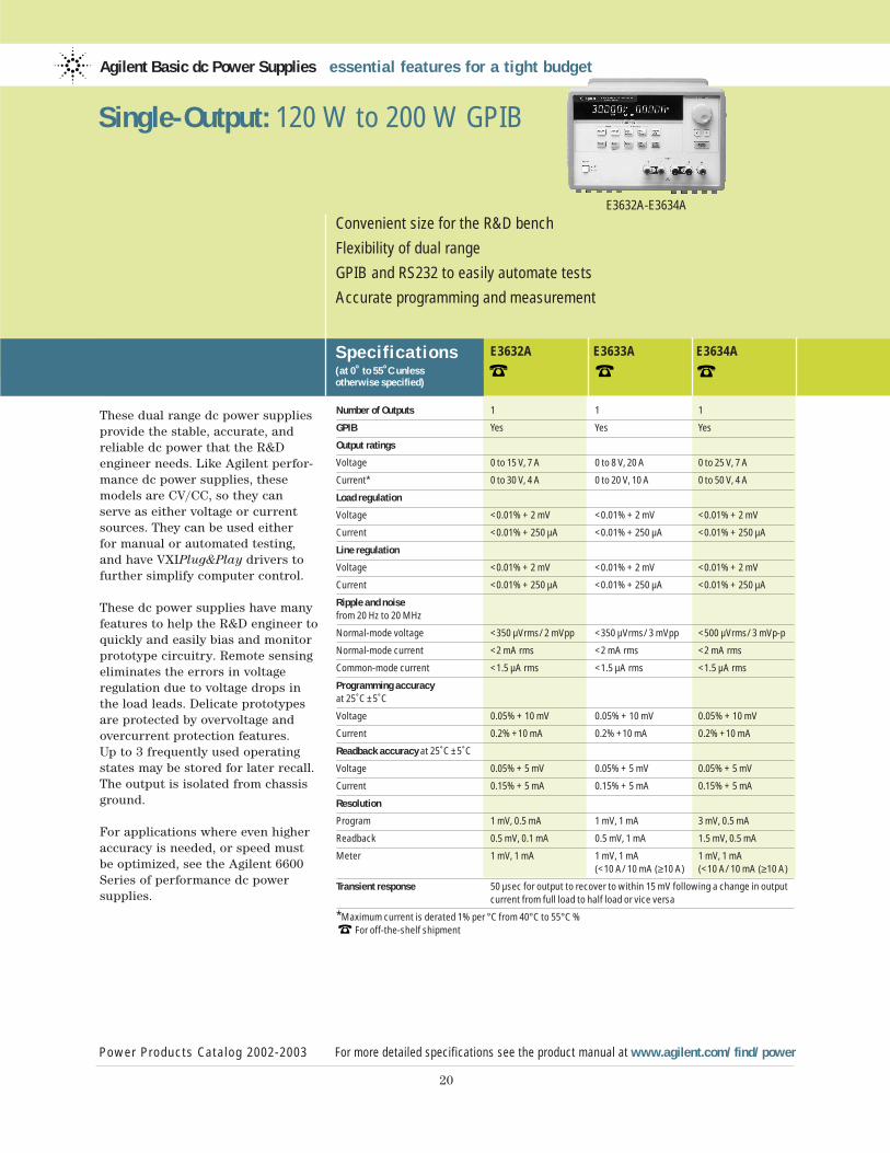
These dual range dc power suppliesprovide the stable, accurate, andreliable dc power that the R&D engineer needs. Like Agilent perfor-mance dc power supplies, thesemodels are CV/CC, so they can serve as either voltage or currentsources. They can be used either for manual or automated testing,and have VXIPlug&Play drivers tofurther simplify computer control.
These dc power supplies have manyfeatures to help the R&D engineer toquickly and easily bias and monitorprototype circuitry. Remote sensingeliminates the errors in voltage regulation due to voltage drops inthe load leads. Delicate prototypesare protected by overvoltage andovercurrent protection features. Up to 3 frequently used operatingstates may be stored for later recall.The output is isolated from chassisground.
For applications where even higheraccuracy is needed, or speed mustbe optimized, see the Agilent 6600Series of performance dc power supplies.
Agilent Basic dc Power Supplies essential features for a tight budget
Specif ications(at 0˚ to 55˚C unless otherwise specified)
E3632A E3633A E3634A
Power Products Catalog 2002-2003 For more detailed specifications see the product manual at www.agilent.com/find/power
20
Convenient size for the R&D bench
Flexibility of dual range
GPIB and RS232 to easily automate tests
Accurate programming and measurement
E3632A-E3634A
Single-Output: 120 W to 200 W GPIB
Number of Outputs 1 1 1
GPIB Yes Yes Yes
Output ratings
Voltage 0 to 15 V, 7 A 0 to 8 V, 20 A 0 to 25 V, 7 A
Current* 0 to 30 V, 4 A 0 to 20 V, 10 A 0 to 50 V, 4 A
Load regulation
Voltage <0.01% + 2 mV <0.01% + 2 mV <0.01% + 2 mV
Current <0.01% + 250 µA <0.01% + 250 µA <0.01% + 250 µA
Line regulation
Voltage <0.01% + 2 mV <0.01% + 2 mV <0.01% + 2 mV
Current <0.01% + 250 µA <0.01% + 250 µA <0.01% + 250 µA
Ripple and noisefrom 20 Hz to 20 MHz
Normal-mode voltage <350 µVrms/2 mVpp <350 µVrms/3 mVpp <500 µVrms/3 mVp-p
Normal-mode current <2 mA rms <2 mA rms <2 mA rms
Common-mode current <1.5 µA rms <1.5 µA rms <1.5 µA rms
Programming accuracy at 25˚C ±5˚C
Voltage 0.05% + 10 mV 0.05% + 10 mV 0.05% + 10 mV
Current 0.2% +10 mA 0.2% +10 mA 0.2% +10 mA
Readback accuracy at 25˚C ±5˚C
Voltage 0.05% + 5 mV 0.05% + 5 mV 0.05% + 5 mV
Current 0.15% + 5 mA 0.15% + 5 mA 0.15% + 5 mA
Resolution
Program 1 mV, 0.5 mA 1 mV, 1 mA 3 mV, 0.5 mA
Readback 0.5 mV, 0.1 mA 0.5 mV, 1 mA 1.5 mV, 0.5 mA
Meter 1 mV, 1 mA 1 mV, 1 mA 1 mV, 1 mA (<10 A/10 mA (≥10 A) (<10 A/10 mA (≥10 A)
Transient response 50 µsec for output to recover to within 15 mV following a change in output current from full load to half load or vice versa
*Maximum current is derated 1% per °C from 40°C to 55°C % For off-the-shelf shipment
21
Supplemental Characteristicsfor all model numbers
Product Regulation: Designed to comply with UL1244, IEC 61010-1; certified with CSA 22.2Meets requirements for CE regulation
Warranty: Three years
Size: 213 mm W x 132 mm H x 348 mm D(8.4 in. x 5.2 in. x 13.7 in.)
Weight: 9.5 kg (21 lbs)
Ordering Information
Opt 0E9 90 to 110 Vac, 47 to 63 Hz (Japan only)Opt 0EM 104 to 126 Vac, 47 to 63 HzOpt 0E3 207 to 253 Vac, 47 to 63 HzOpt 1CM rack mount kit Opt 0L2 extra documentation package
Single-Output: 120 W to 200 W (Continued)
Power Products Catalog 2002-2003 For more detailed specifications see the product manual at www.agilent.com/find/power
Agilent Basic dc Power Supplies essential features for a tight budget
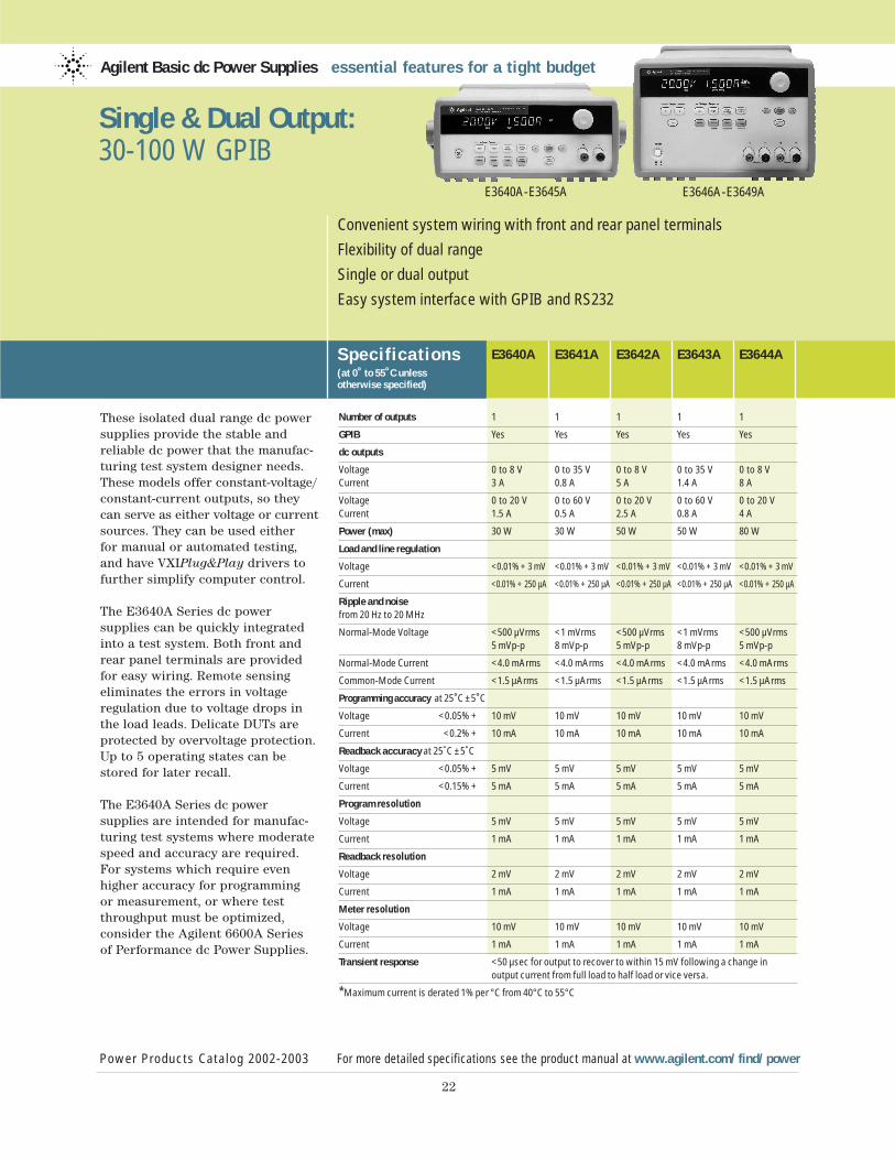
These isolated dual range dc powersupplies provide the stable and reliable dc power that the manufac-turing test system designer needs.These models offer constant-voltage/constant-current outputs, so theycan serve as either voltage or currentsources. They can be used either for manual or automated testing,and have VXIPlug&Play drivers to further simplify computer control.
The E3640A Series dc power supplies can be quickly integratedinto a test system. Both front andrear panel terminals are providedfor easy wiring. Remote sensingeliminates the errors in voltage regulation due to voltage drops inthe load leads. Delicate DUTs areprotected by overvoltage protection.Up to 5 operating states can bestored for later recall.
The E3640A Series dc power supplies are intended for manufac-turing test systems where moderatespeed and accuracy are required.For systems which require evenhigher accuracy for programming or measurement, or where testthroughput must be optimized, consider the Agilent 6600A Series of Performance dc Power Supplies.
Agilent Basic dc Power Supplies essential features for a tight budget
Specif ications(at 0˚ to 55˚C unless otherwise specified)
Power Products Catalog 2002-2003 For more detailed specifications see the product manual at www.agilent.com/find/power
22
Convenient system wiring with front and rear panel terminals
Flexibility of dual range
Single or dual output
Easy system interface with GPIB and RS232
Single & Dual Output: 30-100 W GPIB
E3646A-E3649A
E3640A E3641A E3642A E3643A E3644A
Number of outputs 1 1 1 1 1
GPIB Yes Yes Yes Yes Yes
dc outputs
Voltage 0 to 8 V 0 to 35 V 0 to 8 V 0 to 35 V 0 to 8 VCurrent 3 A 0.8 A 5 A 1.4 A 8 A
Voltage 0 to 20 V 0 to 60 V 0 to 20 V 0 to 60 V 0 to 20 V Current 1.5 A 0.5 A 2.5 A 0.8 A 4 A
Power (max) 30 W 30 W 50 W 50 W 80 W
Load and line regulation
Voltage <0.01% + 3 mV <0.01% + 3 mV <0.01% + 3 mV <0.01% + 3 mV <0.01% + 3 mV
Current <0.01% + 250 µA <0.01% + 250 µA <0.01% + 250 µA <0.01% + 250 µA <0.01% + 250 µA
Ripple and noisefrom 20 Hz to 20 MHz
Normal-Mode Voltage <500 µVrms <1 mVrms <500 µVrms <1 mVrms <500 µVrms 5 mVp-p 8 mVp-p 5 mVp-p 8 mVp-p 5 mVp-p
Normal-Mode Current <4.0 mArms <4.0 mArms <4.0 mArms <4.0 mArms <4.0 mArms
Common-Mode Current <1.5 µArms <1.5 µArms <1.5 µArms <1.5 µArms <1.5 µArms
Programming accuracy at 25˚C ±5˚C
Voltage <0.05% + 10 mV 10 mV 10 mV 10 mV 10 mV
Current <0.2% + 10 mA 10 mA 10 mA 10 mA 10 mA
Readback accuracy at 25˚C ±5˚C
Voltage <0.05% + 5 mV 5 mV 5 mV 5 mV 5 mV
Current <0.15% + 5 mA 5 mA 5 mA 5 mA 5 mA
Program resolution
Voltage 5 mV 5 mV 5 mV 5 mV 5 mV
Current 1 mA 1 mA 1 mA 1 mA 1 mA
Readback resolution
Voltage 2 mV 2 mV 2 mV 2 mV 2 mV
Current 1 mA 1 mA 1 mA 1 mA 1 mA
Meter resolution
Voltage 10 mV 10 mV 10 mV 10 mV 10 mV
Current 1 mA 1 mA 1 mA 1 mA 1 mA
Transient response <50 µsec for output to recover to within 15 mV following a change in output current from full load to half load or vice versa.
*Maximum current is derated 1% per °C from 40°C to 55°C
E3640A-E3645A
23
Supplemental Characteristicsfor all model numbers
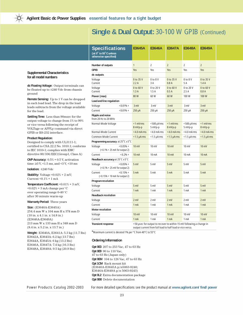
dc Floating Voltage: Output terminals canbe floated up to ±240 Vdc from chassisground
Remote Sensing: Up to 1 V can be droppedin each load lead. The drop in the loadleads subtracts from the voltage availablefor the load.
Settling Time: Less than 90msec for the output voltage to change from 1% to 99%or vice versa following the receipt ofVOLTage or APPLy command via directGPIB or RS-232 interface.
Product Regulation:Designed to comply with UL3111-1; certified to CSA 22.2 No. 1010.1; conformsto IEC 1010-1; complies with EMC directive 89/336/EEC(Group1, Class A)
OVP Accuracy: 0.5% + 0.5 V, activation time: ≥3 V, <1.5 ms, and <3 V, <10 ms
Isolation: ±240 Vdc
Stability: Voltage <0.02% + 2 mV; Current <0.1% + 1 mA
Temperature Coefficient: <0.01% + 3 mV,<0.02% + 3 mA change per˚C over operating range 0-40˚C after 30 minute warm-up
Warranty Period: Three years
Size: (E3640A-E3645A)254.4 mm W x 104 mm H x 374 mm D (10 in. x 4.1 in. x 14.8 in.)(E3646A-E3649A)213 mm W x 133 mm H x 348 mm D (8.4 in. x 5.2 in. x 13.7 in.)
Weight: E3640A, E3641A: 5.3 kg (11.7 lbs)E3642A, E3643A: 6.2 kg (13.7 lbs)E3644A, E3645A: 6 kg (13.2 lbs)E3646A, E3647A: 7.4 kg (16.3 lbs)E3648A, E3649A: 9.5 kg (20.9 lbs)
Single & Dual Output: 30-100 W GPIB (Continued)
Specif ications(at 0˚ to 55˚C unless otherwise specified)
Power Products Catalog 2002-2003 For more detailed specifications see the product manual at www.agilent.com/find/power
Agilent Basic dc Power Supplies essential features for a tight budget
E3645A E3646A E3647A E3648A E3649A
Number of outputs 1 2 2 2 2
GPIB Yes Yes Yes Yes Yes
dc outputs
Voltage 0 to 35 V 0 to 8 V 0 to 35 V 0 to 8 V 0 to 35 VCurrent 2.2 A 3 A 0.8 A 5 A 1.4 A
Voltage 0 to 60 V 0 to 20 V 0 to 60 V 0 to 20 V 0 to 60 V Current 1.3 A 1.5 A 0.5 A 2.5 A 0.8 A
Power (max) 80 W 60 W 60 W 100 W 100 W
Load and line regulation
Voltage <0.01% + 3 mV 3 mV 3 mV 3 mV 3 mV
Current <0.01% + 250 µA 250 µA 250 µA 250 µA 250 µA
Ripple and noisefrom 20 Hz to 20 MHz
Normal-Mode Voltage <1 mVrms <500 µVrms <1 mVrms <500 µVrms <1 mVrms 8 mVp-p 5 mVp-p 8 mVp-p 5 mVp-p 8 mVp-p
Normal-Mode Current <4.0 mArms <4.0 mArms <4.0 mArms <4.0 mArms <4.0 mArms
Common-Mode Current <1.5 µArms <1.5 µArms <1.5 µArms <1.5 µArms <1.5 µArms
Programming accuracy at 25˚C ±5˚C
Voltage <0.05% + 10 mV 10 mV 10 mV 10 mV 10 mV(<0.1% + 25 mA for output 2)
Current <0.2% + 10 mA 10 mA 10 mA 10 mA 10 mA
Readback accuracy at 25˚C ±5˚C
Voltage <0.05% + 5 mV 5 mV 5 mV 5 mV 5 mV(<0.1% + 25 mV for output 2)
Current <0.15% + 5 mA 5 mA 5 mA 5 mA 5 mA(<0.15% + 10 mA for output 2)
Program resolution
Voltage 5 mV 5 mV 5 mV 5 mV 5 mV
Current 1 mA 1 mA 1 mA 1 mA 1 mA
Readback resolution
Voltage 2 mV 2 mV 2 mV 2 mV 2 mV
Current 1 mA 1 mA 1 mA 1 mA 1 mA
Meter resolution
Voltage 10 mV 10 mV 10 mV 10 mV 10 mV
Current 1 mA 1 mA 1 mA 1 mA 1 mA
Transient response <50 µsec for output to recover to within 15 mV following a change in output current from full load to half load or vice versa.
*Maximum current is derated 1% per °C from 40°C to 55°C
Ordering Information
Opt 0E3 207 to 253 Vac, 47 to 63 HzOpt 0E9 90 to 110 Vac, 47 to 63 Hz (Japan only)Opt 0EM 104 to 126 Vac, 47 to 63 HzOpt 1CM Rack mount kit (E3640A-E3645A p/n5063-9240; E3646A-E3649A p/n 5063-9243) Opt 0L2 Extra documentation packageOpt 0B0 Delete documentation
Power Products Catalog 2002-2003 www.agilent.com/find/power
24
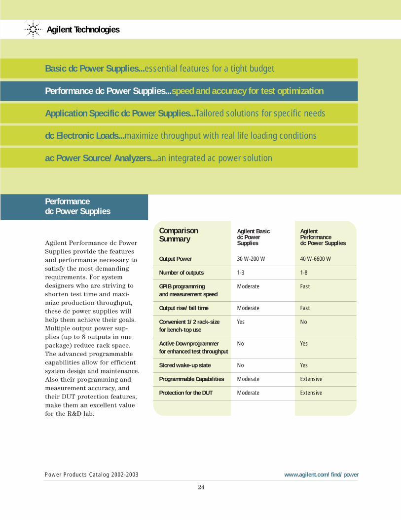
Comparison Agilent Basic Agilent
Summary dc Power Performance Supplies dc Power Supplies
Output Power 30 W-200 W 40 W-6600 W
Number of outputs 1-3 1-8
GPIB programming Moderate Fastand measurement speed
Output rise/fall time Moderate Fast
Convenient 1/2 rack-size Yes No for bench-top use
Active Downprogrammer No Yesfor enhanced test throughput
Stored wake-up state No Yes
Programmable Capabilities Moderate Extensive
Protection for the DUT Moderate Extensive
Agilent Technologies
Basic dc Power Supplies...essential features for a tight budget
Performance dc Power Supplies...speed and accuracy for test optimization
Application Specific dc Power Supplies...Tailored solutions for specific needs
dc Electronic Loads...maximize throughput with real life loading conditions
ac Power Source/Analyzers...an integrated ac power solution
Performance dc Power Supplies
Agilent Performance dc PowerSupplies provide the featuresand performance necessary tosatisfy the most demandingrequirements. For systemdesigners who are striving toshorten test time and maxi-mize production throughput,these dc power supplies willhelp them achieve their goals.Multiple output power sup-plies (up to 8 outputs in onepackage) reduce rack space.The advanced programmablecapabilities allow for efficientsystem design and maintenance.Also their programming andmeasurement accuracy, andtheir DUT protection features,make them an excellent valuefor the R&D lab.
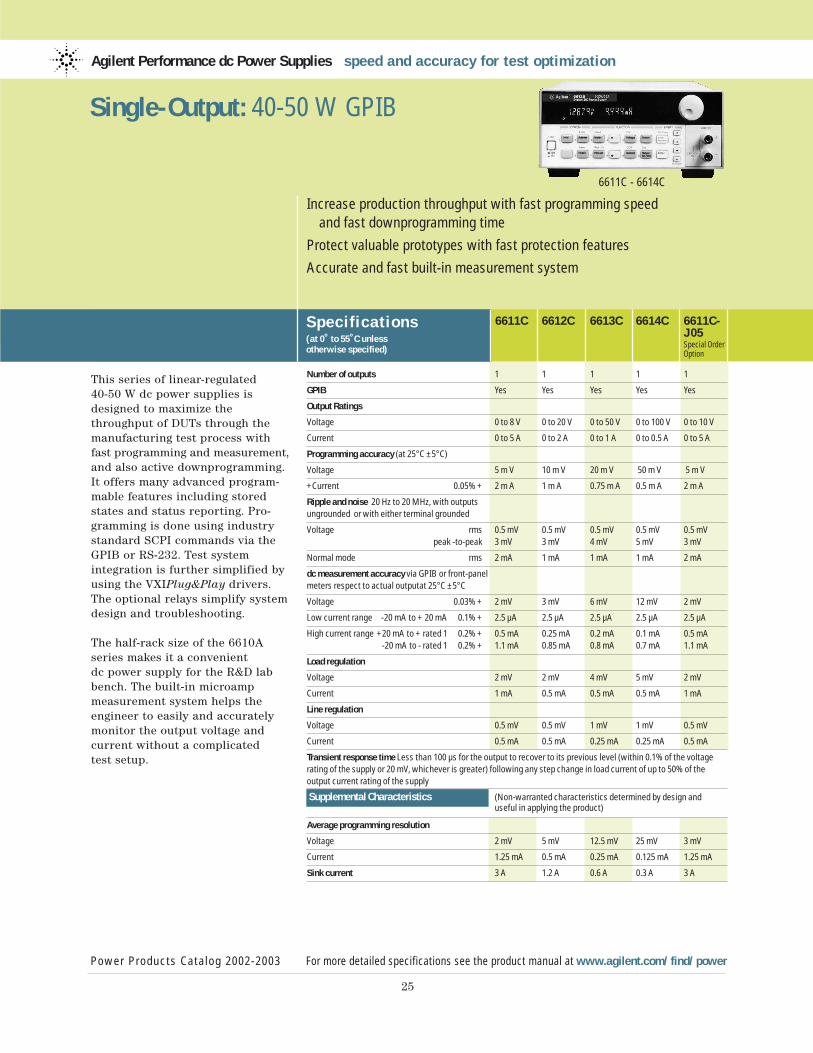
This series of linear-regulated 40-50 W dc power supplies isdesigned to maximize the throughput of DUTs through themanufacturing test process withfast programming and measurement,and also active downprogramming.It offers many advanced program-mable features including storedstates and status reporting. Pro-gramming is done using industrystandard SCPI commands via theGPIB or RS-232. Test system integration is further simplified byusing the VXIPlug&Play drivers.The optional relays simplify systemdesign and troubleshooting.
The half-rack size of the 6610Aseries makes it a convenient dc power supply for the R&D labbench. The built-in microamp measurement system helps the engineer to easily and accuratelymonitor the output voltage and current without a complicated test setup.
Agilent Performance dc Power Supplies speed and accuracy for test optimization
Power Products Catalog 2002-2003 For more detailed specifications see the product manual at www.agilent.com/find/power
25
Increase production throughput with fast programming speed and fast downprogramming time
Protect valuable prototypes with fast protection features
Accurate and fast built-in measurement system
6611C - 6614C
Single-Output: 40-50 W GPIB
Specif ications(at 0˚ to 55˚C unless otherwise specified)
6611C 6612C 6613C 6614C 6611C-J05Special OrderOption
Number of outputs 1 1 1 1 1
GPIB Yes Yes Yes Yes Yes
Output Ratings
Voltage 0 to 8 V 0 to 20 V 0 to 50 V 0 to 100 V 0 to 10 V
Current 0 to 5 A 0 to 2 A 0 to 1 A 0 to 0.5 A 0 to 5 A
Programming accuracy (at 25°C ±5°C)
Voltage 5 m V 10 m V 20 m V 50 m V 5 m V
+Current 0.05% + 2 m A 1 m A 0.75 m A 0.5 m A 2 m A
Ripple and noise 20 Hz to 20 MHz, with outputs ungrounded or with either terminal grounded
Voltage rms 0.5 mV 0.5 mV 0.5 mV 0.5 mV 0.5 mVpeak -to-peak 3 mV 3 mV 4 mV 5 mV 3 mV
Normal mode rms 2 mA 1 mA 1 mA 1 mA 2 mA
dc measurement accuracy via GPIB or front-panel meters respect to actual outputat 25°C ±5°C
Voltage 0.03% + 2 mV 3 mV 6 mV 12 mV 2 mV
Low current range -20 mA to + 20 mA 0.1% + 2.5 µA 2.5 µA 2.5 µA 2.5 µA 2.5 µA
High current range +20 mA to + rated 1 0.2% + 0.5 mA 0.25 mA 0.2 mA 0.1 mA 0.5 mA-20 mA to - rated 1 0.2% + 1.1 mA 0.85 mA 0.8 mA 0.7 mA 1.1 mA
Load regulation
Voltage 2 mV 2 mV 4 mV 5 mV 2 mV
Current 1 mA 0.5 mA 0.5 mA 0.5 mA 1 mA
Line regulation
Voltage 0.5 mV 0.5 mV 1 mV 1 mV 0.5 mV
Current 0.5 mA 0.5 mA 0.25 mA 0.25 mA 0.5 mA
Transient response time Less than 100 µs for the output to recover to its previous level (within 0.1% of the voltage rating of the supply or 20 mV, whichever is greater) following any step change in load current of up to 50% of the output current rating of the supply
Supplemental Characteristics (Non-warranted characteristics determined by design and useful in applying the product)
Average programming resolution
Voltage 2 mV 5 mV 12.5 mV 25 mV 3 mV
Current 1.25 mA 0.5 mA 0.25 mA 0.125 mA 1.25 mA
Sink current 3 A 1.2 A 0.6 A 0.3 A 3 A
26
Supplemental Characteristicsfor all model numbers
dc Floating Voltage: Output terminals can be floated up to ±240 Vdcmaximum from chassis ground
Remote Sensing: Up to two volts droppedin each load lead. Add 2 mV to the voltage load regulation specification for each one volt change in the postiveoutput lead due to load current change.
Command Processing Time: Average timerequired for the output voltage to beginto change following receipt of digital dateis 4 ms for the power supplies connecteddirectly to the GPIB.
Output Programming Response Time: The rise and fall time (10/90% and 90/10%) of the output voltage is less than 2 ms.The output voltage change settles within1 LSB (0.025% x rated voltage) of finalvalue in less than 6 ms.
GPIB Interface Capabilities: IEEE-488.2,SCPI command set, and 6630A Seriesprogramming compatability
Input Power: (full load): 1.6 A, 100 W(6611C: 2.2 A, 120 W)
Regulatory Compliance: Complies with EMC directive 89/336/EEC (ISM 1B).
Warranty Period: Three years
Size: 212.8 mm W x 88.1 mm H x 368.3 mm D (8.4 in x 3.5 in x 14.5 in)See page 102 for more details
Weight: 8.2 kg (18.16 lb) net; 10.6 kg (23.5 lb) shipping
Single-Output: 40-50 W GPIB (Continued)
Power Products Catalog 2002-2003 For more detailed specifications see the product manual at www.agilent.com/find/power
Agilent Performance dc Power Supplies speed and accuracy for test optimization
Ordering Information
Opt 100 87 to 106 Vac, 47 to 63 Hz
Opt 120 104 to 127 Vac, 47 to 63 Hz
Opt 220 191 to 233 Vac, 47 to 63 Hz
Opt 230 207 to 253 Vac, 47 to 63 Hz
Opt 760 Isolation and Reversal relays
* Opt ICM Rack-mount Kit (p/n 5063-9240)
* Opt AXS Rack-mount Kit side-by-side mounting of two units, Lock-link Kit p/n 5061-9694; Flange Kit p/n 5062-3974
Opt 0L2 Additional standard documentation package
Opt 0B3 Service Manual
*Support rails required
AccessoriesRack-mount and slide for two side-by-side units of different lengths p/n 1494-0015, 5063-9255 and fillerpanel 5002-3999
Rack-mount slide and support for oneinstrument p/n 1494-0015, 5063-9255and filler panel 5002-3999
E3663AC Support rails for Agilent rackcabinets
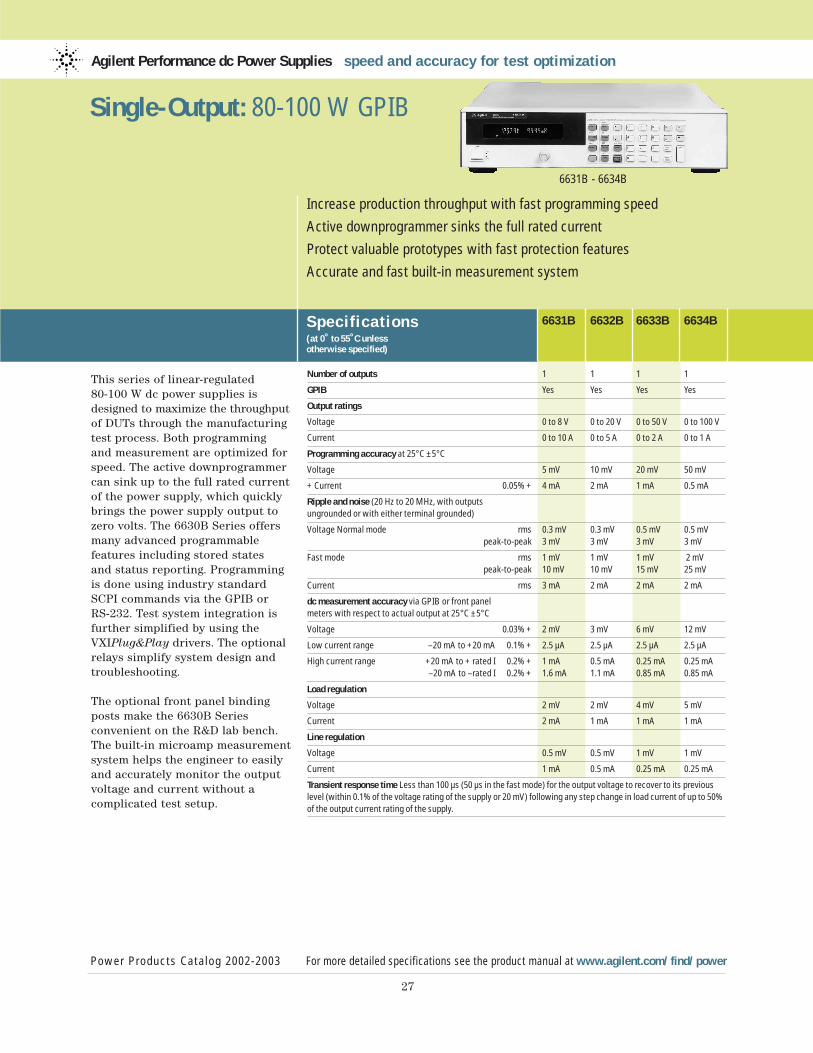
This series of linear-regulated 80-100 W dc power supplies isdesigned to maximize the throughputof DUTs through the manufacturingtest process. Both programming and measurement are optimized forspeed. The active downprogrammercan sink up to the full rated currentof the power supply, which quicklybrings the power supply output tozero volts. The 6630B Series offersmany advanced programmable features including stored states and status reporting. Programmingis done using industry standardSCPI commands via the GPIB or RS-232. Test system integration isfurther simplified by using the VXIPlug&Play drivers. The optionalrelays simplify system design andtroubleshooting.
The optional front panel bindingposts make the 6630B Series convenient on the R&D lab bench.The built-in microamp measurementsystem helps the engineer to easilyand accurately monitor the outputvoltage and current without a complicated test setup.
Agilent Performance dc Power Supplies speed and accuracy for test optimization
Specif ications(at 0˚ to 55˚C unless otherwise specified)
6631B 6632B 6633B 6634B
Power Products Catalog 2002-2003 For more detailed specifications see the product manual at www.agilent.com/find/power
27
Increase production throughput with fast programming speed
Active downprogrammer sinks the full rated current
Protect valuable prototypes with fast protection features
Accurate and fast built-in measurement system
6631B - 6634B
Single-Output: 80-100 W GPIB
Number of outputs 1 1 1 1
GPIB Yes Yes Yes Yes
Output ratings
Voltage 0 to 8 V 0 to 20 V 0 to 50 V 0 to 100 V
Current 0 to 10 A 0 to 5 A 0 to 2 A 0 to 1 A
Programming accuracy at 25°C ±5°C
Voltage 5 mV 10 mV 20 mV 50 mV
+ Current 0.05% + 4 mA 2 mA 1 mA 0.5 mA
Ripple and noise (20 Hz to 20 MHz, with outputs ungrounded or with either terminal grounded)
Voltage Normal mode rms 0.3 mV 0.3 mV 0.5 mV 0.5 mVpeak-to-peak 3 mV 3 mV 3 mV 3 mV
Fast mode rms 1 mV 1 mV 1 mV 2 mVpeak-to-peak 10 mV 10 mV 15 mV 25 mV
Current rms 3 mA 2 mA 2 mA 2 mA
dc measurement accuracy via GPIB or front panel meters with respect to actual output at 25°C ±5°C
Voltage 0.03% + 2 mV 3 mV 6 mV 12 mV
Low current range –20 mA to +20 mA 0.1% + 2.5 µA 2.5 µA 2.5 µA 2.5 µA
High current range +20 mA to + rated I 0.2% + 1 mA 0.5 mA 0.25 mA 0.25 mA–20 mA to –rated I 0.2% + 1.6 mA 1.1 mA 0.85 mA 0.85 mA
Load regulation
Voltage 2 mV 2 mV 4 mV 5 mV
Current 2 mA 1 mA 1 mA 1 mA
Line regulation
Voltage 0.5 mV 0.5 mV 1 mV 1 mV
Current 1 mA 0.5 mA 0.25 mA 0.25 mA
Transient response time Less than 100 µs (50 µs in the fast mode) for the output voltage to recover to its previous level (within 0.1% of the voltage rating of the supply or 20 mV) following any step change in load current of up to 50% of the output current rating of the supply.
28
Supplemental Characteristicsfor all model numbers
dc Floating Voltage: Output terminals canbe floated up to ±240 Vdc maximum fromchassis ground
Remote Sensing: Up to two volts droppedin each load lead. Add 2 mV to the voltageload regulation specification for each onevolt change in the positive output leaddue to load current change.
Command-Processing Time: Average timerequired for the output voltage to begin tochange following receipt of digital data is4 ms for the power supplies connecteddirectly to the GPIB. (Display disabled).
Output-Programming Response Time: Therise and fall time (10/90% and 90/10%) of the output voltage is less than 2 ms(400 µs in fast mode). The output voltagechange settles within 1 LSB (0.025% xrated voltage) of final value in less than 6 ms (2 ms in the fast mode).
GPIB Interface Capabilities: IEEE-488.2,SCPI command set and 6630A Series programming compatability
Measurement Time: Average time to make a voltage or current measurement is 50 ms.
Input Power (full load): 3.5 A, 250 W
Regulatory Compliance: Complies withEMC directive 89/336/EEC (ISM 1B).
Warranty Period: Three years
Size: 425.5 mm W x 88.1 mm H x 364.4 mm D (16.8 in x 3.5 in x 14.3 in).See page 103 for more information
Weight: Net, 12.7 kg (28 lb) net; 15.0 kg (33 lb) shipping
Single-Output: 80-100 W GPIB (Continued)
Specif ications(at 0˚ to 55˚C unless otherwise specified)
Power Products Catalog 2002-2003 For more detailed specifications see the product manual at www.agilent.com/find/power
Agilent Performance dc Power Supplies speed and accuracy for test optimization
Specif ications(at 0˚ to 55˚C unless otherwise specified)
6631B 6632B 6633B 6634B
Supplemental Characteristics (Non-warranted characteristics determined by design and useful in applying the product)
Average programming resolution
Voltage 2 mV 5 mV 12.5 mV 25 mV
Current 2.5 mA 1.25 mA 0.5 mA 0.25 mA
Sink current 10 A 5 A 2 A 1 A
Sink current tracking
SCPI mode 0.4% + 0.4% + 0.4% + 0.4% +4 mA 2 mA 1 mA 0.5 mA
Compatability mode -500 mA -250 mA -100 mA -50 mA
Minimum current in constant current mode* 40 mA 20 mA 8 mA 4 mA
*When programming in the 6630A Series language compatibility mode.
Ordering Information
Opt 100 87 to 106 Vac, 47 to 63 Hz
Opt 120 104 to 127 Vac, 47 to 63 Hz
Opt 220 191 to 233 Vac, 47 to 63 Hz
Opt 230 207 to 253 Vac, 47 to 63 Hz
Opt 020 Front-panel Binding Posts
Opt 760 Isolation and Reversal Relays(N/A on 6631B)
* Opt 1CM Rack-mount Kit,p/n 5063-9212
* Opt 1CP Rack-mount Kit with Handles,p/n 5063-9219Opt 0L2 Additional standarddocumentation packageOpt 0B3 Service Manual
* Support rails required
Accessories
p/n 1494-0060 Rack Slide Kit
E3663AC Support rails for Agilentrack cabinets
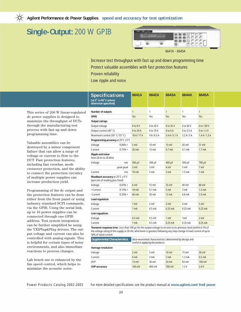
This series of 200 W linear-regulateddc power supplies is designed tomaximize the throughput of DUTsthrough the manufacturing testprocess with fast up and down programming time.
Valuable assemblies can bedestroyed by a minor componentfailure that can allow a surge ofvoltage or current to flow to theDUT. Fast protection features,including fast crowbar, modecrossover protection, and the abilityto connect the protection circuitryof multiple power supplies canincrease production yield.
Programming of the dc output andthe protection features can be doneeither from the front panel or usingindustry standard SCPI commands,via the GPIB. Using the serial link,up to 16 power supplies can be connected through one GPIBaddress. Test system integration can be further simplified be usingthe VXIPlug&Play drivers. The out-put voltage and current can also be controlled with analog signals. Thisis helpful for certain types of noisyenvironments, and also immediatereactions to process changes.
Lab bench use is enhanced by thefan speed control, which helps tominimize the acoustic noise.
Agilent Performance dc Power Supplies speed and accuracy for test optimization
Specif ications(at 0˚ to 55˚C unless otherwise specified)
Power Products Catalog 2002-2003 For more detailed specifications see the product manual at www.agilent.com/find/power
29
Increase test throughput with fast up and down programming time
Protect valuable assemblies with fast protection features
Proven reliability
Low ripple and noise
6641A - 6645A
Single-Output: 200 W GPIB
6641A 6642A 6643A 6644A 6645A
Number of outputs 1 1 1 1 1
GPIB Yes Yes Yes Yes Yes
Output ratings
Output voltage 0 to 8 V 0 to 20 V 0 to 35 V 0 to 60 V 0 to 120 V
Output current (40° C) 0 to 20 A 0 to 10 A 0 to 6 A 0 to 3.5 A 0 to 1.5 A
Maximum current (50° C/55° C) 18 A/17 A 9 A/8.5 A 5.4 A/5.1 A 3.2 A/3 A 1.4 A/1.3 A
Programming accuracy at 25°C ±5°C
Voltage 0.06% + 5 mV 10 mV 15 mV 26 mV 51 mV
Current 0.15% + 26 mA 13 mA 6.7 mA 4.1 mA 1.7 mA
Ripple and noisefrom 20 Hz to 20 MHz
Voltage rms 300 µV 300 µV 400 µV 500 µV 700 µV
peak-peak 3 mV 3 mV 4 mV 5 mV 7 mV
Current rms 10 mA 5 mA 3 mA 1.5 mA 1 mA
Readback accuracy at 25°C ±5°C (percent of reading plus fixed)
Voltage 0.07% + 6 mV 15 mV 25 mV 40 mV 80 mV
+Current 0.15% + 18 mA 9.1 mA 5 mA 3 mA 1.3 mA
-Current 0.35% + 40 mA 20 mA 12 mA 6.8 mA 2.9 mA
Load regulation
Voltage 1 mV 2 mV 3 mV 4 mV 5 mV
Current 1 mA 0.5 mA 0.25 mA 0.25 mA 0.25 mA
Line regualtion
Voltage 0.5 mV 0.5 mV 1 mV 1mV 2 mV
Current 1 mA 0.5 mA 0.25 mA 0.25 mA 0.25 mA
Transient response time Less than 100 µs for the output voltage to recover to its previous level (within 0.1% of the voltage rating of the supply or 20 mV, whichever is greater) following any step change in load current of up to 50% of rated current
Supplemental Characteristics (Non-warranted characteristics determined by design and useful in applying the product)
Average resolution
Voltage 2 mV 5 mV 10 mV 15 mV 30 mV
Current 6 mA 3 mA 2 mA 1.2 mA 0.5 mA
OVP 13 mV 30 mV 54 mV 93 mV 190 mV
OVP accuracy 160 mV 400 mV 700 mV 1.2 V 2.4 V
30
Supplemental Characteristicsfor all model numbers
dc Floating Voltage: Output terminals can be floated up to ±240 Vdc from chassis ground
Remote Sensing: Up to half the rated output voltage can be dropped in eachload lead. The drop in the load leads subtracts from the voltage available for the load.
Command Processing Time: Average timerequired for the output voltage to begin tochange following receipt of digital data is20 ms for the power supplies connecteddirectly to the GPIB
Output Programming Response Time: Therise and fall time (10/90% and 90/10%) ofthe output voltage is less than 15 ms. The output voltage change settles within 1 LSB (0.025% x rated voltage) of finalvalue in less than 60 ms.
Down Programming: An active down programmer sinks approximately20% of the rated output current
Modulation: (Analog programming of output voltage and current)Input Signal: 0 to –5 VInput Impedance: 10 k Ohm nominal
ac Input: (ac input frequency 47 to 63 Hz)Voltage 100 Vac 120 Vac 220 Vac 240 VacCurrent 4.4 A 3.8 A 2.2 A 2.0 A
Input Power 480 VA, 400 W at full load; 60 W at no load
GPIB Interface Capabilities SH1, AH1, T6,L4, SR1, RL1, PP0, DC1, DT1, E1, and C0.IEEE-488.2 and SCPI-compatible com-mand set
Regulatory Compliance: Complies with UL 3111-1, IEC 61010-1.
Size: 425.5 mm W x 88.1 mm H x 439 mm D (16.75 in x 3.5 in x 17.3 in)See page 101 for more details.
Weight: Net, 14.2 kg (31.4 lb); shipping,16.3 kg (36 lb)
Warranty Period: Three years
Single-Output: 200 W GPIB (Continued)
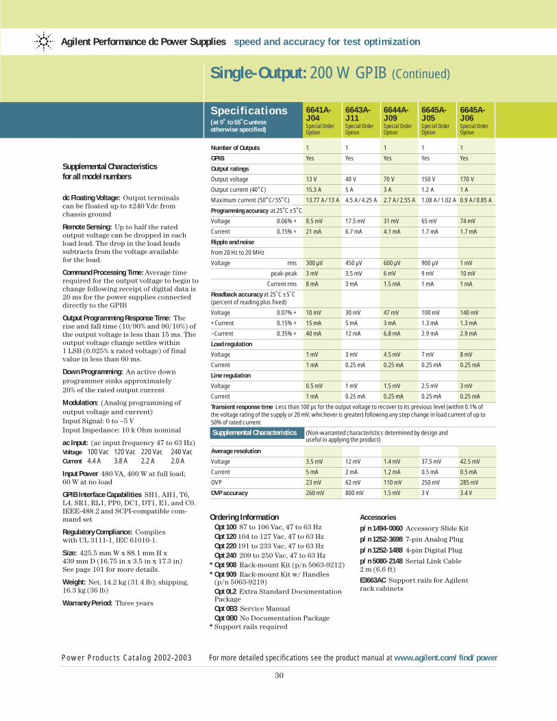
Specif ications(at 0˚ to 55˚C unless otherwise specified)
6641A- 6643A- 6644A- 6645A- 6645A-J04 J11 J09 J05 J06Special Order Special Order Special Order Special Order Special OrderOption Option Option Option Option
Number of Outputs 1 1 1 1 1
GPIB Yes Yes Yes Yes Yes
Output ratings
Output voltage 13 V 40 V 70 V 150 V 170 V
Output current (40˚C) 15.3 A 5 A 3 A 1.2 A 1 A
Maximum current (50˚C/55˚C) 13.77 A/13 A 4.5 A/4.25 A 2.7 A/2.55 A 1.08 A/1.02 A 0.9 A/0.85 A
Programming accuracy at 25˚C ±5˚C
Voltage 0.06% + 8.5 mV 17.5 mV 31 mV 65 mV 74 mV
Current 0.15% + 21 mA 6.7 mA 4.1 mA 1.7 mA 1.7 mA
Ripple and noise
from 20 Hz to 20 MHz
Voltage rms 300 µV 450 µV 600 µV 900 µV 1 mV
peak-peak 3 mV 3.5 mV 6 mV 9 mV 10 mV
Current rms 8 mA 3 mA 1.5 mA 1 mA 1 mA
Readback accuracy at 25˚C ±5˚C (percent of reading plus fixed)
Voltage 0.07% + 10 mV 30 mV 47 mV 100 mV 140 mV
+Current 0.15% + 15 mA 5 mA 3 mA 1.3 mA 1.3 mA
–Current 0.35% + 40 mA 12 mA 6.8 mA 2.9 mA 2.9 mA
Load regulation
Voltage 1 mV 3 mV 4.5 mV 7 mV 8 mV
Current 1 mA 0.25 mA 0.25 mA 0.25 mA 0.25 mA
Line regulation
Voltage 0.5 mV 1 mV 1.5 mV 2.5 mV 3 mV
Current 1 mA 0.25 mA 0.25 mA 0.25 mA 0.25 mA
Transient response time Less than 100 µs for the output voltage to recover to its previous level (within 0.1% of the voltage rating of the supply or 20 mV, whichever is greater) following any step change in load current of up to 50% of rated current
Supplemental Characteristics (Non-warranted characteristics determined by design and useful in applying the product)
Average resolution
Voltage 3.5 mV 12 mV 1.4 mV 37.5 mV 42.5 mV
Current 5 mA 2 mA 1.2 mA 0.5 mA 0.5 mA
OVP 23 mV 62 mV 110 mV 250 mV 285 mV
OVP accuracy 260 mV 800 mV 1.5 mV 3 V 3.4 V
Power Products Catalog 2002-2003 For more detailed specifications see the product manual at www.agilent.com/find/power
Agilent Performance dc Power Supplies speed and accuracy for test optimization
Ordering InformationOpt 100 87 to 106 Vac, 47 to 63 Hz Opt 120 104 to 127 Vac, 47 to 63 Hz Opt 220 191 to 233 Vac, 47 to 63 Hz Opt 240 209 to 250 Vac, 47 to 63 Hz
* Opt 908 Rack-mount Kit (p/n 5063-9212)* Opt 909 Rack-mount Kit w/ Handles
(p/n 5063-9219)Opt 0L2 Extra Standard DocumentationPackageOpt 0B3 Service ManualOpt 0B0 No Documentation Package
* Support rails required
Accessories
p/n 1494-0060 Accessory Slide Kit
p/n 1252-3698 7-pin Analog Plug
p/n 1252-1488 4-pin Digital Plug
p/n 5080-2148 Serial Link Cable 2 m (6.6 ft)
E3663AC Support rails for Agilent rack cabinets
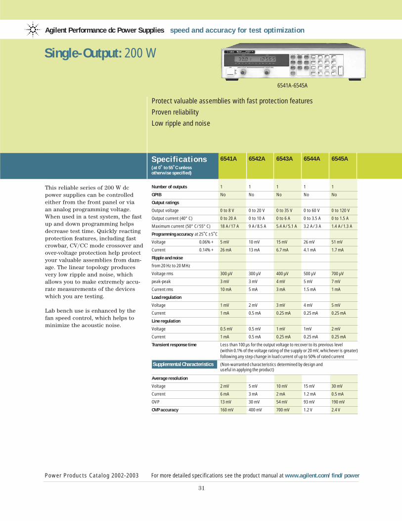
This reliable series of 200 W dcpower supplies can be controlledeither from the front panel or via an analog programming voltage.When used in a test system, the fastup and down programming helpsdecrease test time. Quickly reactingprotection features, including fastcrowbar, CV/CC mode crossover andover-voltage protection help protectyour valuable assemblies from dam-age. The linear topology producesvery low ripple and noise, whichallows you to make extremely accu-rate measurements of the deviceswhich you are testing.
Lab bench use is enhanced by thefan speed control, which helps tominimize the acoustic noise.
Agilent Performance dc Power Supplies speed and accuracy for test optimization
Power Products Catalog 2002-2003 For more detailed specifications see the product manual at www.agilent.com/find/power
31
Protect valuable assemblies with fast protection features
Proven reliability
Low ripple and noise
6541A-6545A
Single-Output: 200 W
Specif ications(at 0˚ to 55˚C unless otherwise specified)
6541A 6542A 6543A 6544A 6545A
Number of outputs 1 1 1 1 1
GPIB No No No No No
Output ratings
Output voltage 0 to 8 V 0 to 20 V 0 to 35 V 0 to 60 V 0 to 120 V
Output current (40° C) 0 to 20 A 0 to 10 A 0 to 6 A 0 to 3.5 A 0 to 1.5 A
Maximum current (50° C/55° C) 18 A/17 A 9 A/8.5 A 5.4 A/5.1 A 3.2 A/3 A 1.4 A/1.3 A
Programming accuracy at 25˚C ±5˚C
Voltage 0.06% + 5 mV 10 mV 15 mV 26 mV 51 mV
Current 0.14% + 26 mA 13 mA 6.7 mA 4.1 mA 1.7 mA
Ripple and noise
from 20 Hz to 20 MHz
Voltage rms 300 µV 300 µV 400 µV 500 µV 700 µV
peak-peak 3 mV 3 mV 4 mV 5 mV 7 mV
Current rms 10 mA 5 mA 3 mA 1.5 mA 1 mA
Load regulation
Voltage 1 mV 2 mV 3 mV 4 mV 5 mV
Current 1 mA 0.5 mA 0.25 mA 0.25 mA 0.25 mA
Line regulation
Voltage 0.5 mV 0.5 mV 1 mV 1mV 2 mV
Current 1 mA 0.5 mA 0.25 mA 0.25 mA 0.25 mA
Transient response time Less than 100 µs for the output voltage to recover to its previous level (within 0.1% of the voltage rating of the supply or 20 mV, whichever is greater) following any step change in load current of up to 50% of rated current
Supplemental Characteristics (Non-warranted characteristics determined by design and useful in applying the product)
Average resolution
Voltage 2 mV 5 mV 10 mV 15 mV 30 mV
Current 6 mA 3 mA 2 mA 1.2 mA 0.5 mA
OVP 13 mV 30 mV 54 mV 93 mV 190 mV
OVP accuracy 160 mV 400 mV 700 mV 1.2 V 2.4 V
32
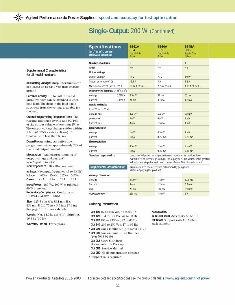
Supplemental Characteristicsfor all model numbers
dc Floating Voltage: Output terminals canbe floated up to ±240 Vdc from chassisground
Remote Sensing: Up to half the rated output voltage can be dropped in eachload lead. The drop in the load leads subtracts from the voltage available forthe load.
Output Programming Response Time: Therise and fall time (10/90% and 90/10%) of the output voltage is less than 15 ms.The output voltage change settles within1 LSB (0.025% x rated voltage) offinal value in less than 60 ms.
Down Programming: An active down programmer sinks approximately 20% ofthe rated output current
Modulation: (Analog programming of output voltage and current)Input Signal: 0 to –5 VInput Impedance: 10 k Ohm nominal
ac Input: (ac input frequency 47 to 63 Hz)Voltage 100 Vac 120 Vac 220 Vac 240 Vac
Current 4.4 A 3.8 A 2.2 A 2.0 A
Input Power: 480 VA, 400 W at full load; 60 W at no loadRegulatory Compliance: Conforms toUL1244 and IEC 61010-1.
Size: 425.5 mm W x 88.1 mm H x 439 mm D (16.75 in x 3.5 in x 17.3 in)See page 101 for more details
Weight: Net, 14.2 kg (31.4 lb); shipping,16.3 kg (36 lb)
Warranty Period: Three years
Single-Output: 200 W (Continued)
Specif ications(at 0˚ to 55˚C unless otherwise specified)
Power Products Catalog 2002-2003 For more detailed specifications see the product manual at www.agilent.com/find/power
Agilent Performance dc Power Supplies speed and accuracy for test optimization
6541A- 6544A- 6545A-J04 J09 J05Special Order Special Order Special OrderOption Option Option
Number of outputs 1 1 1
GPIB No No No
Output ratings
Output voltage 13 V 70 V 150 V
Output current (40° C) 15.3 A 3 A 1.2 A
Maximum current (50° C/55° C) 13.77 A/13 A 2.7 A/2.55 A 1.08 A/1.02 A
Programming accuracy at 25˚C ±5˚C
Voltage 0.06% + 8.5 mV 31 mV 65 mV
Current 0.15% + 21 mA 4.1 mA 1.7 mA
Ripple and noise
from 20 Hz to 20 MHz
Voltage rms 300 µV 600 µV 900 µV
peak-peak 3 mV 6 mV 9 mV
Current rms 8 mA 1.5 mA 1 mA
Load regulation
Voltage 1 mV 4.5 mV 7 mV
Current 1 mA 0.25 mA 0.25 mA
Line regulation
Voltage 0.5 mV 1.5 mV 2.5 mV
Current 1 mA 0.25 mA 0.25 mA
Transient response time Less than 100 µs for the output voltage to recover to its previous level (within 0.1% of the voltage rating of the supply or 20 mV, whichever is greater) following any step change in load current of up to 50% of rated current
Supplemental Characteristics (Non-warranted characteristics determined by design and useful in applying the product)
Average resolution
Voltage 3.5 mV 1.4 mV 37.5 mV
Current 5 mA 1.2 mA 0.5 mA
OVP 23 mV 110 mV 250 mV
OVP accuracy 260 mV 1.5 mV 3 V
Ordering Information
Opt 100 87 to 106 Vac, 47 to 63 HzOpt 120 104 to 127 Vac, 47 to 63 HzOpt 220 191 to 233 Vac, 47 to 63 HzOpt 240 209 to 250 Vac, 47 to 63 Hz
* Opt 908 Rack-mount Kit (p/n 5063-9212)* Opt 909 Rack-mount Kit w/ Handles
(p/n 5063-9219)Opt 0L2 Extra Standard Documentation PackageOpt 0B3 Service ManualOpt 0B0 No documentation package
* Support rails required
Accessoriesp/n 1494-0060 Accessory Slide Kit E3663AC Support rails for Agilent rack cabinets
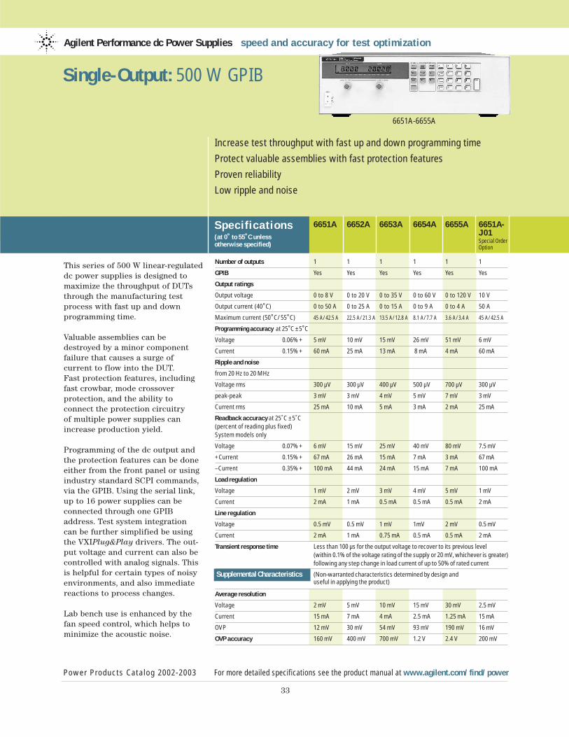
This series of 500 W linear-regulateddc power supplies is designed tomaximize the throughput of DUTsthrough the manufacturing testprocess with fast up and down programming time.
Valuable assemblies can bedestroyed by a minor componentfailure that causes a surge of current to flow into the DUT. Fast protection features, includingfast crowbar, mode crossover protection, and the ability to connect the protection circuitry of multiple power supplies canincrease production yield.
Programming of the dc output andthe protection features can be doneeither from the front panel or usingindustry standard SCPI commands,via the GPIB. Using the serial link,up to 16 power supplies can be connected through one GPIBaddress. Test system integration can be further simplified be usingthe VXIPlug&Play drivers. The out-put voltage and current can also be controlled with analog signals. Thisis helpful for certain types of noisyenvironments, and also immediatereactions to process changes.
Lab bench use is enhanced by thefan speed control, which helps tominimize the acoustic noise.
Agilent Performance dc Power Supplies speed and accuracy for test optimization
Specif ications(at 0˚ to 55˚C unless otherwise specified)
6651A 6652A 6653A 6654A 6655A 6651A-J01Special OrderOption
Power Products Catalog 2002-2003 For more detailed specifications see the product manual at www.agilent.com/find/power
33
Increase test throughput with fast up and down programming time
Protect valuable assemblies with fast protection features
Proven reliability
Low ripple and noise
6651A-6655A
Single-Output: 500 W GPIB
Number of outputs 1 1 1 1 1 1
GPIB Yes Yes Yes Yes Yes Yes
Output ratings
Output voltage 0 to 8 V 0 to 20 V 0 to 35 V 0 to 60 V 0 to 120 V 10 V
Output current (40˚C) 0 to 50 A 0 to 25 A 0 to 15 A 0 to 9 A 0 to 4 A 50 A
Maximum current (50˚C/55˚C) 45 A/42.5 A 22.5 A/21.3 A 13.5 A/12.8 A 8.1 A/7.7 A 3.6 A/3.4 A 45 A/42.5 A
Programming accuracy at 25˚C ±5˚C
Voltage 0.06% + 5 mV 10 mV 15 mV 26 mV 51 mV 6 mV
Current 0.15% + 60 mA 25 mA 13 mA 8 mA 4 mA 60 mA
Ripple and noise
from 20 Hz to 20 MHz
Voltage rms 300 µV 300 µV 400 µV 500 µV 700 µV 300 µV
peak-peak 3 mV 3 mV 4 mV 5 mV 7 mV 3 mV
Current rms 25 mA 10 mA 5 mA 3 mA 2 mA 25 mA
Readback accuracy at 25˚C ±5˚C (percent of reading plus fixed) System models only
Voltage 0.07% + 6 mV 15 mV 25 mV 40 mV 80 mV 7.5 mV
+Current 0.15% + 67 mA 26 mA 15 mA 7 mA 3 mA 67 mA
–Current 0.35% + 100 mA 44 mA 24 mA 15 mA 7 mA 100 mA
Load regulation
Voltage 1 mV 2 mV 3 mV 4 mV 5 mV 1 mV
Current 2 mA 1 mA 0.5 mA 0.5 mA 0.5 mA 2 mA
Line regulation
Voltage 0.5 mV 0.5 mV 1 mV 1mV 2 mV 0.5 mV
Current 2 mA 1 mA 0.75 mA 0.5 mA 0.5 mA 2 mA
Transient response time Less than 100 µs for the output voltage to recover to its previous level (within 0.1% of the voltage rating of the supply or 20 mV, whichever is greater) following any step change in load current of up to 50% of rated current
Supplemental Characteristics (Non-warranted characteristics determined by design and useful in applying the product)
Average resolution
Voltage 2 mV 5 mV 10 mV 15 mV 30 mV 2.5 mV
Current 15 mA 7 mA 4 mA 2.5 mA 1.25 mA 15 mA
OVP 12 mV 30 mV 54 mV 93 mV 190 mV 16 mV
OVP accuracy 160 mV 400 mV 700 mV 1.2 V 2.4 V 200 mV
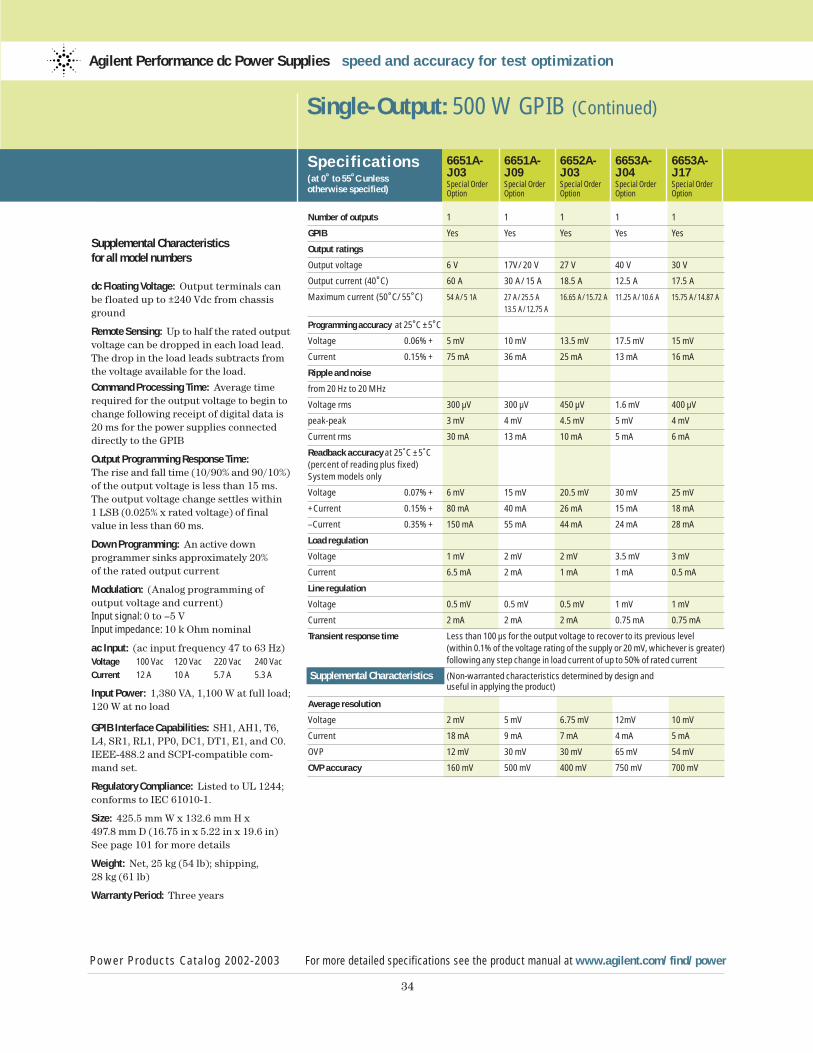
34
Supplemental Characteristicsfor all model numbers
dc Floating Voltage: Output terminals canbe floated up to ±240 Vdc from chassisground
Remote Sensing: Up to half the rated outputvoltage can be dropped in each load lead.The drop in the load leads subtracts fromthe voltage available for the load.
Command Processing Time: Average timerequired for the output voltage to begin tochange following receipt of digital data is20 ms for the power supplies connecteddirectly to the GPIB
Output Programming Response Time:The rise and fall time (10/90% and 90/10%)of the output voltage is less than 15 ms.The output voltage change settles within 1 LSB (0.025% x rated voltage) of finalvalue in less than 60 ms.
Down Programming: An active down programmer sinks approximately 20% of the rated output current
Modulation: (Analog programming of output voltage and current)Input signal: 0 to –5 VInput impedance: 10 k Ohm nominal
ac Input: (ac input frequency 47 to 63 Hz)Voltage 100 Vac 120 Vac 220 Vac 240 Vac
Current 12 A 10 A 5.7 A 5.3 A
Input Power: 1,380 VA, 1,100 W at full load; 120 W at no load
GPIB Interface Capabilities: SH1, AH1, T6,L4, SR1, RL1, PP0, DC1, DT1, E1, and C0.IEEE-488.2 and SCPI-compatible com-mand set.
Regulatory Compliance: Listed to UL 1244;conforms to IEC 61010-1.
Size: 425.5 mm W x 132.6 mm H x 497.8 mm D (16.75 in x 5.22 in x 19.6 in)See page 101 for more details
Weight: Net, 25 kg (54 lb); shipping, 28 kg (61 lb)
Warranty Period: Three years
Single-Output: 500 W GPIB (Continued)
Specif ications(at 0˚ to 55˚C unless otherwise specified)
6651A- 6651A- 6652A- 6653A- 6653A-J03 J09 J03 J04 J17Special Order Special Order Special Order Special Order Special OrderOption Option Option Option Option
Number of outputs 1 1 1 1 1
GPIB Yes Yes Yes Yes Yes
Output ratings
Output voltage 6 V 17V/20 V 27 V 40 V 30 V
Output current (40˚C) 60 A 30 A/15 A 18.5 A 12.5 A 17.5 A
Maximum current (50˚C/55˚C) 54 A/5 1A 27 A/25.5 A 16.65 A/15.72 A 11.25 A/10.6 A 15.75 A/14.87 A
13.5 A/12.75 A
Programming accuracy at 25˚C ±5˚C
Voltage 0.06% + 5 mV 10 mV 13.5 mV 17.5 mV 15 mV
Current 0.15% + 75 mA 36 mA 25 mA 13 mA 16 mA
Ripple and noise
from 20 Hz to 20 MHz
Voltage rms 300 µV 300 µV 450 µV 1.6 mV 400 µV
peak-peak 3 mV 4 mV 4.5 mV 5 mV 4 mV
Current rms 30 mA 13 mA 10 mA 5 mA 6 mA
Readback accuracy at 25˚C ±5˚C (percent of reading plus fixed) System models only
Voltage 0.07% + 6 mV 15 mV 20.5 mV 30 mV 25 mV
+Current 0.15% + 80 mA 40 mA 26 mA 15 mA 18 mA
–Current 0.35% + 150 mA 55 mA 44 mA 24 mA 28 mA
Load regulation
Voltage 1 mV 2 mV 2 mV 3.5 mV 3 mV
Current 6.5 mA 2 mA 1 mA 1 mA 0.5 mA
Line regulation
Voltage 0.5 mV 0.5 mV 0.5 mV 1 mV 1 mV
Current 2 mA 2 mA 2 mA 0.75 mA 0.75 mA
Transient response time Less than 100 µs for the output voltage to recover to its previous level (within 0.1% of the voltage rating of the supply or 20 mV, whichever is greater) following any step change in load current of up to 50% of rated current
Supplemental Characteristics (Non-warranted characteristics determined by design and useful in applying the product)
Average resolution
Voltage 2 mV 5 mV 6.75 mV 12mV 10 mV
Current 18 mA 9 mA 7 mA 4 mA 5 mA
OVP 12 mV 30 mV 30 mV 65 mV 54 mV
OVP accuracy 160 mV 500 mV 400 mV 750 mV 700 mV
Power Products Catalog 2002-2003 For more detailed specifications see the product manual at www.agilent.com/find/power
Agilent Performance dc Power Supplies speed and accuracy for test optimization
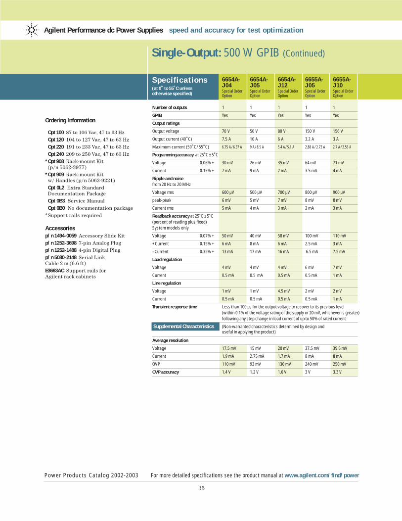
35
Ordering Information
Opt 100 87 to 106 Vac, 47 to 63 HzOpt 120 104 to 127 Vac, 47 to 63 HzOpt 220 191 to 233 Vac, 47 to 63 HzOpt 240 209 to 250 Vac, 47 to 63 Hz
* Opt 908 Rack-mount Kit (p/n 5062-3977)
* Opt 909 Rack-mount Kitw/ Handles (p/n 5063-9221)Opt 0L2 Extra Standard Documentation PackageOpt 0B3 Service ManualOpt 0B0 No documentation package
* Support rails required
Accessoriesp/n 1494-0059 Accessory Slide Kitp/n 1252-3698 7-pin Analog Plugp/n 1252-1488 4-pin Digital Plugp/n 5080-2148 Serial Link Cable 2 m (6.6 ft)E3663AC Support rails for Agilent rack cabinets
Single-Output: 500 W GPIB (Continued)
Specif ications(at 0˚ to 55˚C unless otherwise specified)
6654A- 6654A- 6654A- 6655A- 6655A-J04 J05 J12 J05 J10Special Order Special Order Special Order Special Order Special OrderOption Option Option Option Option
Number of outputs 1 1 1 1 1
GPIB Yes Yes Yes Yes Yes
Output ratings
Output voltage 70 V 50 V 80 V 150 V 156 V
Output current (40˚C) 7.5 A 10 A 6 A 3.2 A 3 A
Maximum current (50˚C/55˚C) 6.75 A/6.37 A 9 A/8.5 A 5.4 A/5.1 A 2.88 A/2.72 A 2.7 A/2.55 A
Programming accuracy at 25˚C ±5˚C
Voltage 0.06% + 30 mV 26 mV 35 mV 64 mV 71 mV
Current 0.15% + 7 mA 9 mA 7 mA 3.5 mA 4 mA
Ripple and noisefrom 20 Hz to 20 MHz
Voltage rms 600 µV 500 µV 700 µV 800 µV 900 µV
peak-peak 6 mV 5 mV 7 mV 8 mV 8 mV
Current rms 5 mA 4 mA 3 mA 2 mA 3 mA
Readback accuracy at 25˚C ±5˚C (percent of reading plus fixed) System models only
Voltage 0.07% + 50 mV 40 mV 58 mV 100 mV 110 mV
+Current 0.15% + 6 mA 8 mA 6 mA 2.5 mA 3 mA
–Current 0.35% + 13 mA 17 mA 16 mA 6.5 mA 7.5 mA
Load regulation
Voltage 4 mV 4 mV 4 mV 6 mV 7 mV
Current 0.5 mA 0.5 mA 0.5 mA 0.5 mA 1 mA
Line regulation
Voltage 1 mV 1 mV 4.5 mV 2 mV 2 mV
Current 0.5 mA 0.5 mA 0.5 mA 0.5 mA 1 mA
Transient response time Less than 100 µs for the output voltage to recover to its previous level (within 0.1% of the voltage rating of the supply or 20 mV, whichever is greater) following any step change in load current of up to 50% of rated current
Supplemental Characteristics (Non-warranted characteristics determined by design and useful in applying the product)
Average resolution
Voltage 17.5 mV 15 mV 20 mV 37.5 mV 39.5 mV
Current 1.9 mA 2.75 mA 1.7 mA 8 mA 8 mA
OVP 110 mV 93 mV 130 mV 240 mV 250 mV
OVP accuracy 1.4 V 1.2 V 1.6 V 3 V 3.3 V
Power Products Catalog 2002-2003 For more detailed specifications see the product manual at www.agilent.com/find/power
Agilent Performance dc Power Supplies speed and accuracy for test optimization
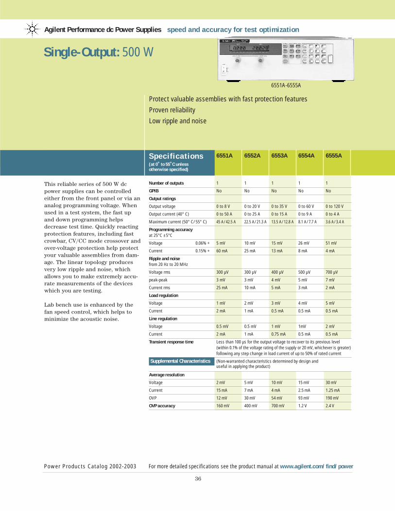
This reliable series of 500 W dcpower supplies can be controlledeither from the front panel or via ananalog programming voltage. Whenused in a test system, the fast upand down programming helpsdecrease test time. Quickly reactingprotection features, including fastcrowbar, CV/CC mode crossover andover-voltage protection help protectyour valuable assemblies from dam-age. The linear topology producesvery low ripple and noise, whichallows you to make extremely accu-rate measurements of the deviceswhich you are testing.
Lab bench use is enhanced by thefan speed control, which helps tominimize the acoustic noise.
Agilent Performance dc Power Supplies speed and accuracy for test optimization
Specif ications(at 0˚ to 55˚C unless otherwise specified)
Power Products Catalog 2002-2003 For more detailed specifications see the product manual at www.agilent.com/find/power
36
Protect valuable assemblies with fast protection features
Proven reliability
Low ripple and noise
Single-Output: 500 W
6551A 6552A 6553A 6554A 6555A
Number of outputs 1 1 1 1 1
GPIB No No No No No
Output ratings
Output voltage 0 to 8 V 0 to 20 V 0 to 35 V 0 to 60 V 0 to 120 V
Output current (40° C) 0 to 50 A 0 to 25 A 0 to 15 A 0 to 9 A 0 to 4 A
Maximum current (50° C/55° C) 45 A/42.5 A 22.5 A/21.3 A 13.5 A/12.8 A 8.1 A/7.7 A 3.6 A/3.4 A
Programming accuracyat 25°C ±5°C
Voltage 0.06% + 5 mV 10 mV 15 mV 26 mV 51 mV
Current 0.15% + 60 mA 25 mA 13 mA 8 mA 4 mA
Ripple and noise from 20 Hz to 20 MHz
Voltage rms 300 µV 300 µV 400 µV 500 µV 700 µV
peak-peak 3 mV 3 mV 4 mV 5 mV 7 mV
Current rms 25 mA 10 mA 5 mA 3 mA 2 mA
Load regulation
Voltage 1 mV 2 mV 3 mV 4 mV 5 mV
Current 2 mA 1 mA 0.5 mA 0.5 mA 0.5 mA
Line regulation
Voltage 0.5 mV 0.5 mV 1 mV 1mV 2 mV
Current 2 mA 1 mA 0.75 mA 0.5 mA 0.5 mA
Transient response time Less than 100 µs for the output voltage to recover to its previous level (within 0.1% of the voltage rating of the supply or 20 mV, whichever is greater)following any step change in load current of up to 50% of rated current
Supplemental Characteristics (Non-warranted characteristics determined by design and useful in applying the product)
Average resolution
Voltage 2 mV 5 mV 10 mV 15 mV 30 mV
Current 15 mA 7 mA 4 mA 2.5 mA 1.25 mA
OVP 12 mV 30 mV 54 mV 93 mV 190 mV
OVP accuracy 160 mV 400 mV 700 mV 1.2 V 2.4 V
6551A-6555A
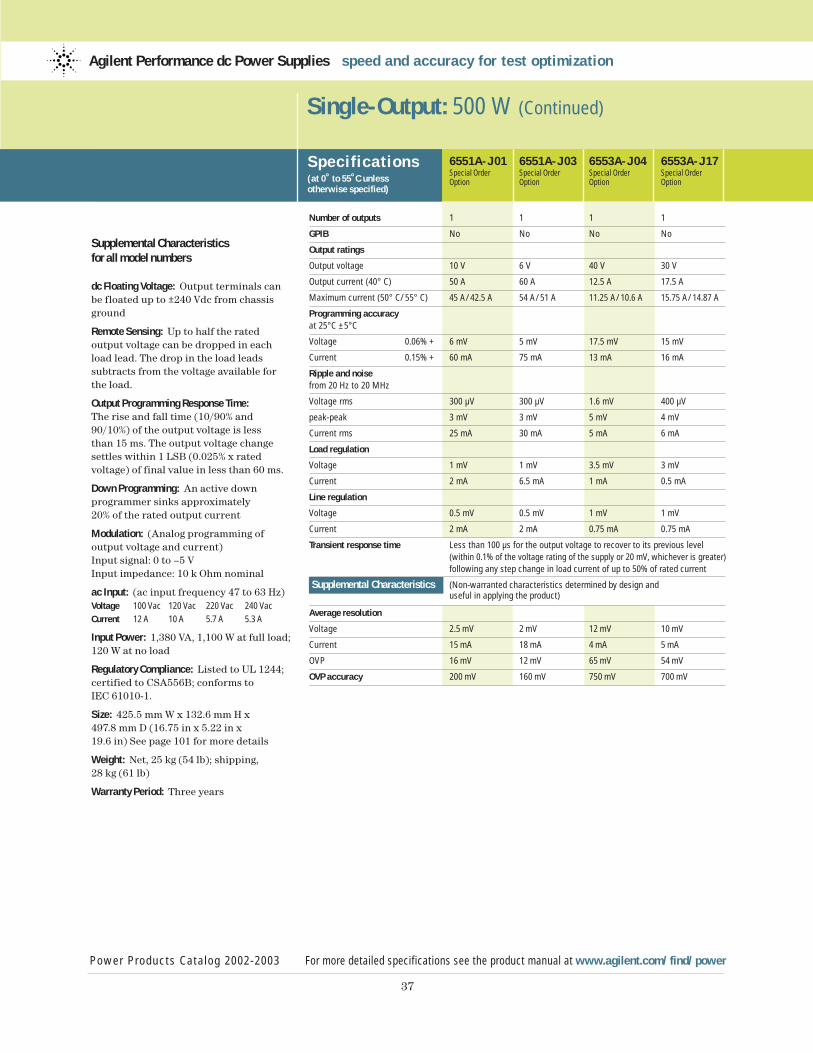
37
Supplemental Characteristicsfor all model numbers
dc Floating Voltage: Output terminals canbe floated up to ±240 Vdc from chassisground
Remote Sensing: Up to half the rated output voltage can be dropped in eachload lead. The drop in the load leads subtracts from the voltage available forthe load.
Output Programming Response Time:The rise and fall time (10/90% and90/10%) of the output voltage is less than 15 ms. The output voltage changesettles within 1 LSB (0.025% x rated voltage) of final value in less than 60 ms.
Down Programming: An active down programmer sinks approximately20% of the rated output current
Modulation: (Analog programming of output voltage and current)Input signal: 0 to –5 VInput impedance: 10 k Ohm nominal
ac Input: (ac input frequency 47 to 63 Hz)Voltage 100 Vac 120 Vac 220 Vac 240 Vac
Current 12 A 10 A 5.7 A 5.3 A
Input Power: 1,380 VA, 1,100 W at full load;120 W at no load
Regulatory Compliance: Listed to UL 1244;certified to CSA556B; conforms to IEC 61010-1.
Size: 425.5 mm W x 132.6 mm H x 497.8 mm D (16.75 in x 5.22 in x19.6 in) See page 101 for more details
Weight: Net, 25 kg (54 lb); shipping, 28 kg (61 lb)
Warranty Period: Three years
Single-Output: 500 W (Continued)
Specif ications(at 0˚ to 55˚C unless otherwise specified)
Power Products Catalog 2002-2003 For more detailed specifications see the product manual at www.agilent.com/find/power
Agilent Performance dc Power Supplies speed and accuracy for test optimization
6551A-J01 6551A-J03 6553A-J04 6553A-J17Special Order Special Order Special Order Special OrderOption Option Option Option
Number of outputs 1 1 1 1
GPIB No No No No
Output ratings
Output voltage 10 V 6 V 40 V 30 V
Output current (40° C) 50 A 60 A 12.5 A 17.5 A
Maximum current (50° C/55° C) 45 A/42.5 A 54 A/51 A 11.25 A/10.6 A 15.75 A/14.87 A
Programming accuracyat 25°C ±5°C
Voltage 0.06% + 6 mV 5 mV 17.5 mV 15 mV
Current 0.15% + 60 mA 75 mA 13 mA 16 mA
Ripple and noise from 20 Hz to 20 MHz
Voltage rms 300 µV 300 µV 1.6 mV 400 µV
peak-peak 3 mV 3 mV 5 mV 4 mV
Current rms 25 mA 30 mA 5 mA 6 mA
Load regulation
Voltage 1 mV 1 mV 3.5 mV 3 mV
Current 2 mA 6.5 mA 1 mA 0.5 mA
Line regulation
Voltage 0.5 mV 0.5 mV 1 mV 1 mV
Current 2 mA 2 mA 0.75 mA 0.75 mA
Transient response time Less than 100 µs for the output voltage to recover to its previous level (within 0.1% of the voltage rating of the supply or 20 mV, whichever is greater)following any step change in load current of up to 50% of rated current
Supplemental Characteristics (Non-warranted characteristics determined by design and useful in applying the product)
Average resolution
Voltage 2.5 mV 2 mV 12 mV 10 mV
Current 15 mA 18 mA 4 mA 5 mA
OVP 16 mV 12 mV 65 mV 54 mV
OVP accuracy 200 mV 160 mV 750 mV 700 mV
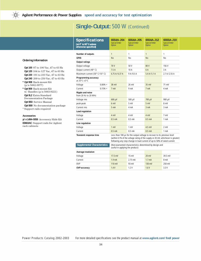
38
Ordering Information
Opt 100 87 to 106 Vac, 47 to 63 HzOpt 120 104 to 127 Vac, 47 to 63 HzOpt 220 191 to 233 Vac, 47 to 63 HzOpt 240 209 to 250 Vac, 47 to 63 Hz
* Opt 908 Rack-mount Kit (p/n 5062-3977)
* Opt 909 Rack-mount Kit w/ Handles (p/n 5063-9221)Opt 0L2 Extra Standard Documentation PackageOpt 0B3 Service ManualOpt 0B0 No documentation package
* Support rails required
Accessoriesp/n 1494-0059 Accessory Slide KitE3663AC Support rails for Agilentrack cabinets
Single-Output: 500 W (Continued)
Specif ications(at 0˚ to 55˚C unless otherwise specified)
Power Products Catalog 2002-2003 For more detailed specifications see the product manual at www.agilent.com/find/power
Agilent Performance dc Power Supplies speed and accuracy for test optimization
Specif ications(at 0˚ to 55˚C unless otherwise specified)
6554A-J04 6554A-J05 6554A-J12 6555A-J10Special Order Special Order Special Order Special OrderOption Option Option Option
Number of outputs 1 1 1 1
GPIB No No No No
Output ratings
Output voltage 70 V 50 V 80 V 156 V
Output current (40° C) 7.5 A 10 A 6 A 3 A
Maximum current (50° C/55° C) 6.75 A/6.37 A 9 A/8.5 A 5.4 A/5.1 A 2.7 A/2.55 A
Programming accuracyat 25°C ±5°C
Voltage 0.06% + 38 mV 26 mV 35 mV 71 mV
Current 0.15% + 7 mA 9 mA 7 mA 4 mA
Ripple and noise from 20 Hz to 20 MHz
Voltage rms 600 µV 500 µV 700 µV 900 µV
peak-peak 6 mV 5 mV 5 mV 8 mV
Current rms 5 mA 4 mA 3 mA 3 mA
Load regulation
Voltage 4 mV 4 mV 4 mV 7 mV
Current 0.5 mA 0.5 mA 0.5 mA 1 mA
Line regulation
Voltage 1 mV 1 mV 4.5 mV 2 mV
Current 0.5 mA 0.5 mA 0.5 mA 1 mA
Transient response time Less than 100 µs for the output voltage to recover to its previous level (within 0.1% of the voltage rating of the supply or 20 mV, whichever is greater)following any step change in load current of up to 50% of rated current
Supplemental Characteristics (Non-warranted characteristics determined by design and useful in applying the product)
Average resolution
Voltage 17.5 mV 15 mV 20 mV 39.5 mV
Current 1.9 mA 2.75 mA 1.7 mA 8 mA
OVP 110 mV 93 mV 130 mV 250 mV
OVP accuracy 1.4 V 1.2 V 1.6 V 3.3 V
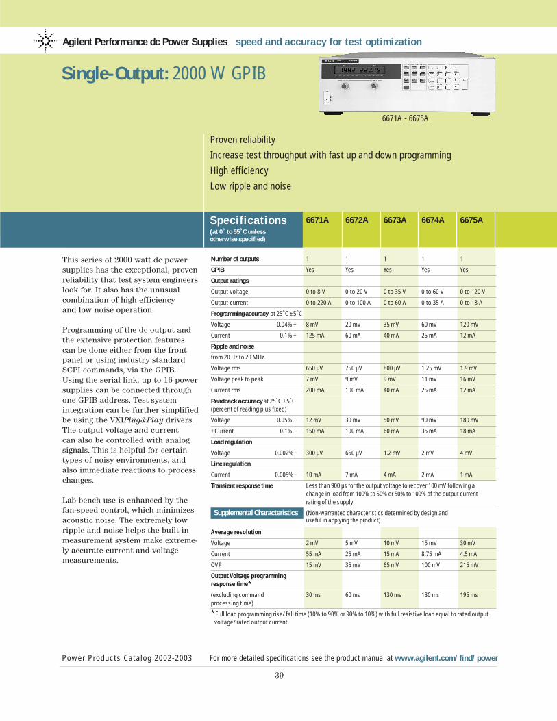
This series of 2000 watt dc powersupplies has the exceptional, provenreliability that test system engineerslook for. It also has the unusualcombination of high efficiency and low noise operation.
Programming of the dc output andthe extensive protection featurescan be done either from the frontpanel or using industry standardSCPI commands, via the GPIB.Using the serial link, up to 16 powersupplies can be connected throughone GPIB address. Test system integration can be further simplifiedbe using the VXIPlug&Play drivers.The output voltage and current can also be controlled with analogsignals. This is helpful for certaintypes of noisy environments, andalso immediate reactions to processchanges.
Lab-bench use is enhanced by thefan-speed control, which minimizesacoustic noise. The extremely lowripple and noise helps the built-inmeasurement system make extreme-ly accurate current and voltage measurements.
Agilent Performance dc Power Supplies speed and accuracy for test optimization
Specif ications(at 0˚ to 55˚C unless otherwise specified)
Power Products Catalog 2002-2003 For more detailed specifications see the product manual at www.agilent.com/find/power
39
Proven reliability
Increase test throughput with fast up and down programming
High efficiency
Low ripple and noise
6671A - 6675A
Single-Output: 2000 W GPIB
6671A 6672A 6673A 6674A 6675A
Number of outputs 1 1 1 1 1
GPIB Yes Yes Yes Yes Yes
Output ratings
Output voltage 0 to 8 V 0 to 20 V 0 to 35 V 0 to 60 V 0 to 120 V
Output current 0 to 220 A 0 to 100 A 0 to 60 A 0 to 35 A 0 to 18 A
Programming accuracy at 25˚C ±5˚C
Voltage 0.04% + 8 mV 20 mV 35 mV 60 mV 120 mV
Current 0.1% + 125 mA 60 mA 40 mA 25 mA 12 mA
Ripple and noise
from 20 Hz to 20 MHz
Voltage rms 650 µV 750 µV 800 µV 1.25 mV 1.9 mV
Voltage peak to peak 7 mV 9 mV 9 mV 11 mV 16 mV
Current rms 200 mA 100 mA 40 mA 25 mA 12 mA
Readback accuracy at 25˚C ±5˚C (percent of reading plus fixed)
Voltage 0.05% + 12 mV 30 mV 50 mV 90 mV 180 mV
±Current 0.1% + 150 mA 100 mA 60 mA 35 mA 18 mA
Load regulation
Voltage 0.002%+ 300 µV 650 µV 1.2 mV 2 mV 4 mV
Line regulation
Current 0.005%+ 10 mA 7 mA 4 mA 2 mA 1 mA
Transient response time Less than 900 µs for the output voltage to recover 100 mV following a change in load from 100% to 50% or 50% to 100% of the output currentrating of the supply
Supplemental Characteristics (Non-warranted characteristics determined by design and useful in applying the product)
Average resolution
Voltage 2 mV 5 mV 10 mV 15 mV 30 mV
Current 55 mA 25 mA 15 mA 8.75 mA 4.5 mA
OVP 15 mV 35 mV 65 mV 100 mV 215 mV
Output Voltage programming
response time*
(excluding command 30 ms 60 ms 130 ms 130 ms 195 msprocessing time)
* Full load programming rise/fall time (10% to 90% or 90% to 10%) with full resistive load equal to rated output voltage/rated output current.
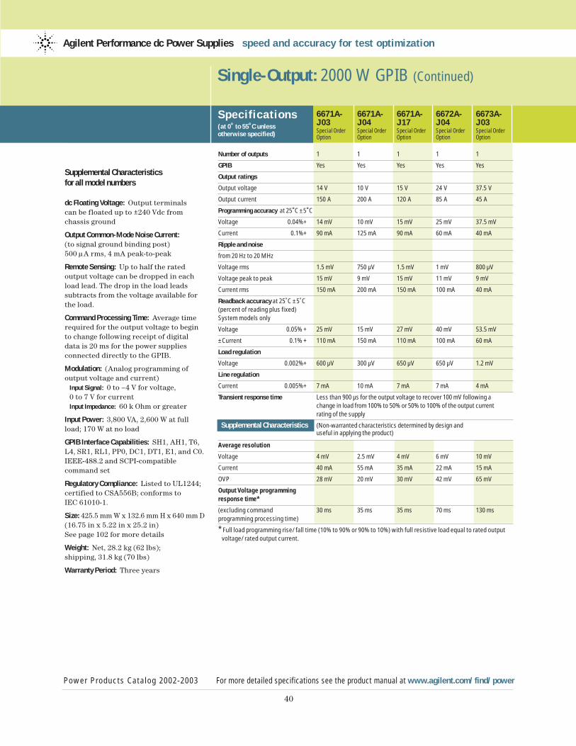
40
Supplemental Characteristicsfor all model numbers
dc Floating Voltage: Output terminals can be floated up to ±240 Vdc from chassis ground
Output Common-Mode Noise Current:(to signal ground binding post)500 µA rms, 4 mA peak-to-peak
Remote Sensing: Up to half the rated output voltage can be dropped in eachload lead. The drop in the load leads subtracts from the voltage available forthe load.
Command Processing Time: Average timerequired for the output voltage to beginto change following receipt of digital data is 20 ms for the power supplies connected directly to the GPIB.
Modulation: (Analog programming of output voltage and current)
Input Signal: 0 to –4 V for voltage, 0 to 7 V for currentInput Impedance: 60 k Ohm or greater
Input Power: 3,800 VA, 2,600 W at full load; 170 W at no load
GPIB Interface Capabilities: SH1, AH1, T6,L4, SR1, RL1, PP0, DC1, DT1, E1, and C0.IEEE-488.2 and SCPI-compatiblecommand set
Regulatory Compliance: Listed to UL1244;certified to CSA556B; conforms to IEC 61010-1.
Size: 425.5 mm W x 132.6 mm H x 640 mm D(16.75 in x 5.22 in x 25.2 in)See page 102 for more details
Weight: Net, 28.2 kg (62 lbs); shipping, 31.8 kg (70 lbs)
Warranty Period: Three years
Single-Output: 2000 W GPIB (Continued)
Specif ications(at 0˚ to 55˚C unless otherwise specified)
6671A- 6671A- 6671A- 6672A- 6673A-J03 J04 J17 J04 J03Special Order Special Order Special Order Special Order Special OrderOption Option Option Option Option
Number of outputs 1 1 1 1 1
GPIB Yes Yes Yes Yes Yes
Output ratings
Output voltage 14 V 10 V 15 V 24 V 37.5 V
Output current 150 A 200 A 120 A 85 A 45 A
Programming accuracy at 25˚C ±5˚C
Voltage 0.04%+ 14 mV 10 mV 15 mV 25 mV 37.5 mV
Current 0.1%+ 90 mA 125 mA 90 mA 60 mA 40 mA
Ripple and noise
from 20 Hz to 20 MHz
Voltage rms 1.5 mV 750 µV 1.5 mV 1 mV 800 µV
Voltage peak to peak 15 mV 9 mV 15 mV 11 mV 9 mV
Current rms 150 mA 200 mA 150 mA 100 mA 40 mA
Readback accuracy at 25˚C ±5˚C (percent of reading plus fixed) System models only
Voltage 0.05% + 25 mV 15 mV 27 mV 40 mV 53.5 mV
±Current 0.1% + 110 mA 150 mA 110 mA 100 mA 60 mA
Load regulation
Voltage 0.002%+ 600 µV 300 µV 650 µV 650 µV 1.2 mV
Line regulation
Current 0.005%+ 7 mA 10 mA 7 mA 7 mA 4 mA
Transient response time Less than 900 µs for the output voltage to recover 100 mV following a change in load from 100% to 50% or 50% to 100% of the output currentrating of the supply
Supplemental Characteristics (Non-warranted characteristics determined by design and useful in applying the product)
Average resolution
Voltage 4 mV 2.5 mV 4 mV 6 mV 10 mV
Current 40 mA 55 mA 35 mA 22 mA 15 mA
OVP 28 mV 20 mV 30 mV 42 mV 65 mV
Output Voltage programming
response time*
(excluding command 30 ms 35 ms 35 ms 70 ms 130 msprogramming processing time)
* Full load programming rise/fall time (10% to 90% or 90% to 10%) with full resistive load equal to rated output voltage/rated output current.
Power Products Catalog 2002-2003 For more detailed specifications see the product manual at www.agilent.com/find/power
Agilent Performance dc Power Supplies speed and accuracy for test optimization
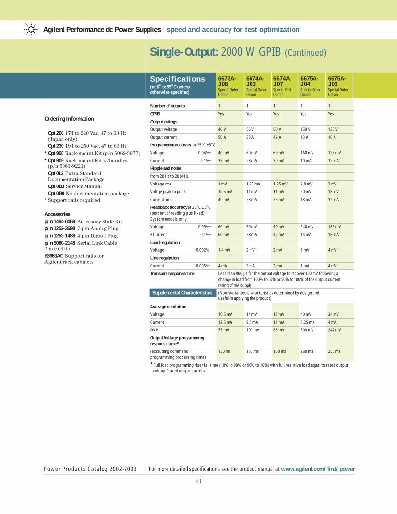
41
Ordering Information
Opt 200 174 to 220 Vac, 47 to 63 Hz(Japan only)Opt 230 191 to 250 Vac, 47 to 63 Hz
* Opt 908 Rack-mount Kit (p/n 5062-3977)* Opt 909 Rack-mount Kit w/handles
(p/n 5063-9221)Opt 0L2 Extra Standard Documentation PackageOpt 0B3 Service ManualOpt 0B0 No documentation package
* Support rails required
Accessoriesp/n 1494-0059 Accessory Slide Kitp/n 1252-3698 7-pin Analog Plugp/n 1252-1488 4-pin Digital Plugp/n 5080-2148 Serial Link Cable 2 m (6.6 ft)E3663AC Support rails for Agilent rack cabinets
Single-Output: 2000 W GPIB (Continued)
Specif ications(at 0˚ to 55˚C unless otherwise specified)
6673A- 6674A- 6674A- 6675A- 6675A-J08 J03 J07 J04 J06Special Order Special Order Special Order Special Order Special OrderOption Option Option Option Option
Number of outputs 1 1 1 1 1
GPIB Yes Yes Yes Yes Yes
Output ratings
Output voltage 40 V 56 V 50 V 160 V 135 V
Output current 50 A 38 A 42 A 13 A 16 A
Programming accuracy at 25˚C ±5˚C
Voltage 0.04%+ 40 mV 60 mV 60 mV 160 mV 125 mV
Current 0.1%+ 35 mA 28 mA 30 mA 10 mA 12 mA
Ripple and noise
from 20 Hz to 20 MHz
Voltage rms 1 mV 1.25 mV 1.25 mV 2.8 mV 2 mV
Voltge peak to peak 10.5 mV 11 mV 11 mV 20 mV 18 mV
Current rms 40 mA 28 mA 25 mA 18 mA 12 mA
Readback accuracy at 25˚C ±5˚C (percent of reading plus fixed) System models only
Voltage 0.05%+ 60 mV 90 mV 90 mV 240 mV 185 mV
±Current 0.1%+ 60 mA 38 mA 42 mA 14 mA 18 mA
Load regulation
Voltage 0.002%+ 1.4 mV 2 mV 2 mV 6 mV 4 mV
Line regulation
Current 0.005%+ 4 mA 2 mA 2 mA 1 mA 4 mV
Transient response time Less than 900 µs for the output voltage to recover 100 mV following a change in load from 100% to 50% or 50% to 100% of the output currentrating of the supply
Supplemental Characteristics (Non-warranted characteristics determined by design and useful in applying the product)
Average resolution
Voltage 10.5 mV 14 mV 12 mV 40 mV 34 mV
Current 12.5 mA 9.5 mA 11 mA 3.25 mA 4 mA
OVP 75 mV 100 mV 85 mV 300 mV 242 mV
Output Voltage programming
response time*
(excluding command 130 ms 130 ms 130 ms 280 ms 250 msprogramming processing time)
* Full load programming rise/fall time (10% to 90% or 90% to 10%) with full resistive load equal to rated output voltage/rated output current.
Power Products Catalog 2002-2003 For more detailed specifications see the product manual at www.agilent.com/find/power
Agilent Performance dc Power Supplies speed and accuracy for test optimization
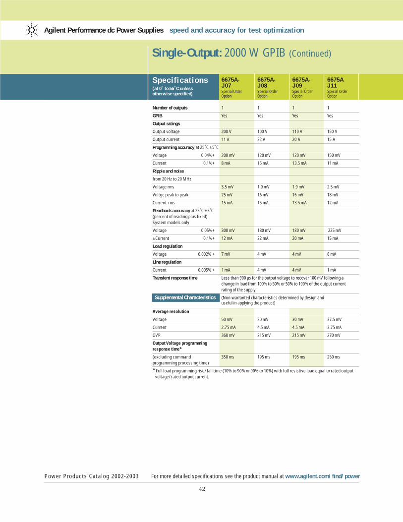
42
Single-Output: 2000 W GPIB (Continued)
Specif ications(at 0˚ to 55˚C unless otherwise specified)
6675A- 6675A- 6675A- 6675AJ07 J08 J09 J11Special Order Special Order Special Order Special OrderOption Option Option Option
Number of outputs 1 1 1 1
GPIB Yes Yes Yes Yes
Output ratings
Output voltage 200 V 100 V 110 V 150 V
Output current 11 A 22 A 20 A 15 A
Programming accuracy at 25˚C ±5˚C
Voltage 0.04%+ 200 mV 120 mV 120 mV 150 mV
Current 0.1%+ 8 mA 15 mA 13.5 mA 11 mA
Ripple and noise
from 20 Hz to 20 MHz
Voltage rms 3.5 mV 1.9 mV 1.9 mV 2.5 mV
Voltge peak to peak 25 mV 16 mV 16 mV 18 mV
Current rms 15 mA 15 mA 13.5 mA 12 mA
Readback accuracy at 25˚C ±5˚C (percent of reading plus fixed) System models only
Voltage 0.05%+ 300 mV 180 mV 180 mV 225 mV
±Current 0.1%+ 12 mA 22 mA 20 mA 15 mA
Load regulation
Voltage 0.002% + 7 mV 4 mV 4 mV 6 mV
Line regulation
Current 0.005% + 1 mA 4 mV 4 mV 1 mA
Transient response time Less than 900 µs for the output voltage to recover 100 mV following a change in load from 100% to 50% or 50% to 100% of the output currentrating of the supply
Supplemental Characteristics (Non-warranted characteristics determined by design and useful in applying the product)
Average resolution
Voltage 50 mV 30 mV 30 mV 37.5 mV
Current 2.75 mA 4.5 mA 4.5 mA 3.75 mA
OVP 360 mV 215 mV 215 mV 270 mV
Output Voltage programming
response time*
(excluding command 350 ms 195 ms 195 ms 250 msprogramming processing time)
* Full load programming rise/fall time (10% to 90% or 90% to 10%) with full resistive load equal to rated output voltage/rated output current.
Power Products Catalog 2002-2003 For more detailed specifications see the product manual at www.agilent.com/find/power
Agilent Performance dc Power Supplies speed and accuracy for test optimization
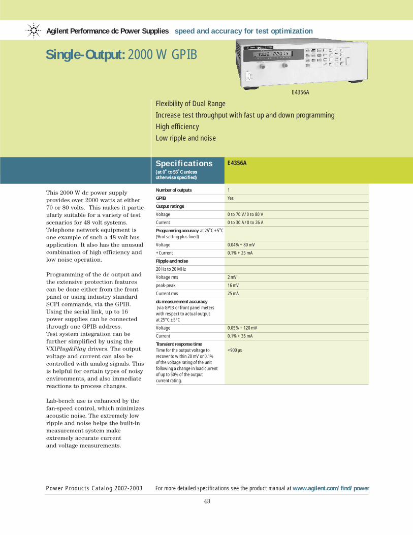
This 2000 W dc power supply provides over 2000 watts at either70 or 80 volts. This makes it partic-ularly suitable for a variety of testscenarios for 48 volt systems.Telephone network equipment isone example of such a 48 volt busapplication. It also has the unusualcombination of high efficiency andlow noise operation.
Programming of the dc output andthe extensive protection featurescan be done either from the frontpanel or using industry standardSCPI commands, via the GPIB.Using the serial link, up to 16 power supplies can be connectedthrough one GPIB address. Test system integration can be further simplified by using theVXIPlug&Play drivers. The outputvoltage and current can also be controlled with analog signals. Thisis helpful for certain types of noisyenvironments, and also immediatereactions to process changes.
Lab-bench use is enhanced by thefan-speed control, which minimizesacoustic noise. The extremely lowripple and noise helps the built-inmeasurement system make extremely accurate current and voltage measurements.
Agilent Performance dc Power Supplies speed and accuracy for test optimization
Specif ications(at 0˚ to 55˚C unless otherwise specified)
E4356A
Power Products Catalog 2002-2003 For more detailed specifications see the product manual at www.agilent.com/find/power
43
Flexibility of Dual Range
Increase test throughput with fast up and down programming
High efficiency
Low ripple and noise
E4356A
Single-Output: 2000 W GPIB
Number of outputs 1
GPIB Yes
Output ratings
Voltage 0 to 70 V/0 to 80 V
Current 0 to 30 A/0 to 26 A
Programming accuracy at 25˚C ±5˚C(% of setting plus fixed)
Voltage 0.04% + 80 mV
+Current 0.1% + 25 mA
Ripple and noise
20 Hz to 20 MHz
Voltage rms 2 mV
peak-peak 16 mV
Current rms 25 mA
dc measurement accuracy (via GPIB or front panel meters with respect to actual output at 25°C ±5°C
Voltage 0.05% + 120 mV
Current 0.1% + 35 mA
Transient response timeTime for the output voltage to <900 µsrecover to within 20 mV or 0.1%of the voltage rating of the unitfollowing a change in load current of up to 50% of the output current rating.
44
Supplemental Characteristicsfor all model numbers
dc Floating Voltage: Output terminals can be floated up to ±240 Vdc maximum fromchassis ground.
Remote Sensing: Up to half the rated output voltage can be dropped in eachload lead. The drop in the load leads subtracts from the voltage available forthe load.
Command Processing Time: Average timerequired for the output voltage to beginto change following receipt of digital data is 20 ms for the power supplies connected directly to the GPIB.(Display disabled.)
Output Voltage Rise Time/Fall Time:100 ms/200 ms for output to change from90% to 10% or from 10% to 90% of its totalexcursion with full resistive load(excludes command processing time).
Modulation: (Analog programming of output voltage and current)Input Signal: 0 to -4 V for voltage and currentInput Impedance: 60 k Ohm nominal
Input Power: 3800 VA, 2600 W at full load;100 W at no load
GPIB Interface Capabilities: SH1, AH1, TE6,LE4, SR1, RL1, PP0, DC1, DT1, E1 andC0. IEEE-488.2 and SCPI-compatiblecommand set
Regulatory Compliance: Listed to UL1244;certified to CSA556B, conforms toEN61010.
Warranty Period: Three years
Size: 425.5 mm W x 132.6 mm H x 640 mm D(16.75 in. x 5.22 in. x 25.2 in.)See page 102 for more details
Weight: 27.7 kg (61 lbs) net, 31.4 kg (69 lbs) shipping.
Ordering Information
Opt 200 174 to 220 Vac, 47 to 63 Hz (Japan only)Opt 230 191 to 250 Vac, 47 to 63 Hz
* Opt 908 Rack-mount Kit (p/n 5062-3977)* Opt 909 Rack-mount Kit w/Handles
(p/n 5063-9221)Opt 0L2 Extra Standard Documentation PackageOpt 0B3 Service ManualOpt 0B0 No Documentation PackageSee pages 93-98 for information on line cord options.
* Support rails required
Accessoriesp/n 1494-0059 Accessory Slide Kitp/n 1252-3698 7-pin Analog Plugp/n 1252-1488 4-pin Digitial Plugp/n 5080-2148 Serial Link Cable 2 m (6.6 ft)E3663AC Support rails for Agilent rack cabinets
Single-Output: 2000 W GPIB (Continued)
Power Products Catalog 2002-2003 For more detailed specifications see the product manual at www.agilent.com/find/power
Agilent Performance dc Power Supplies speed and accuracy for test optimization
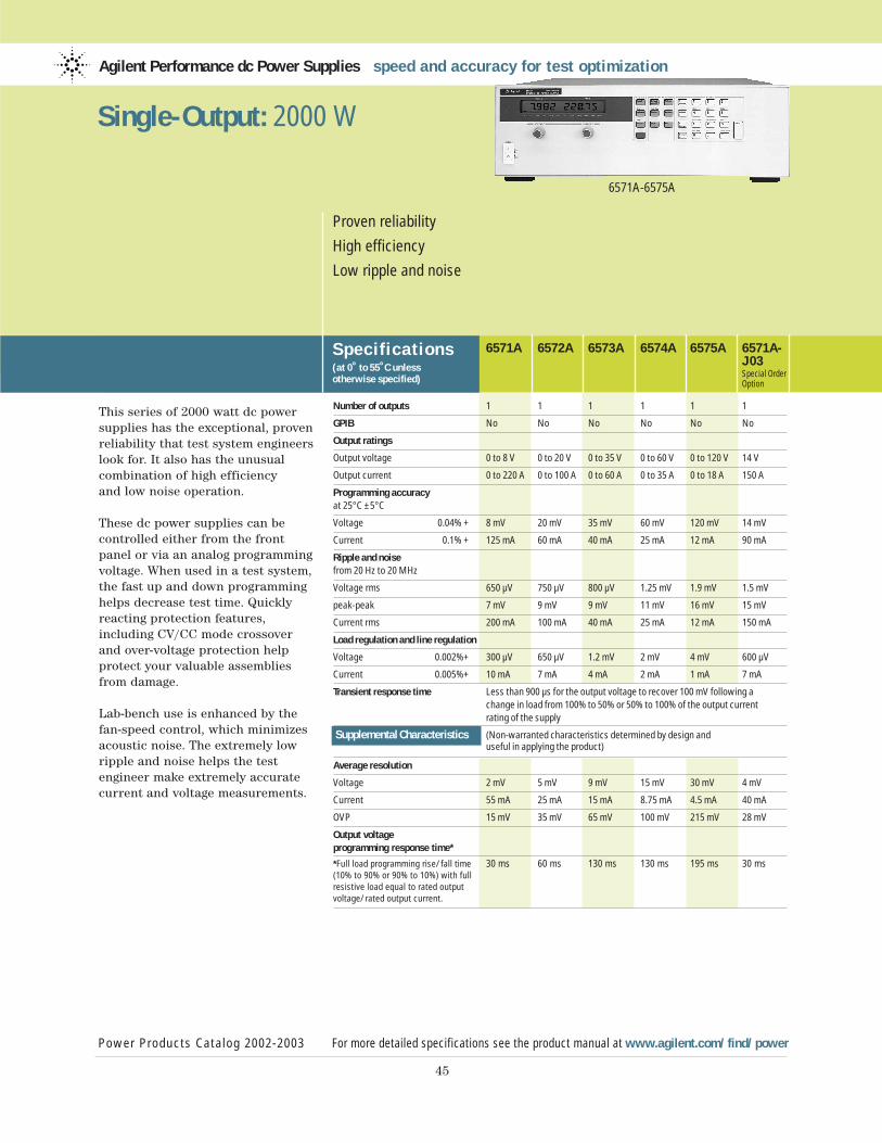
This series of 2000 watt dc powersupplies has the exceptional, provenreliability that test system engineerslook for. It also has the unusualcombination of high efficiency and low noise operation.
These dc power supplies can be controlled either from the frontpanel or via an analog programmingvoltage. When used in a test system,the fast up and down programminghelps decrease test time. Quicklyreacting protection features, including CV/CC mode crossoverand over-voltage protection helpprotect your valuable assembliesfrom damage.
Lab-bench use is enhanced by thefan-speed control, which minimizesacoustic noise. The extremely lowripple and noise helps the test engineer make extremely accuratecurrent and voltage measurements.
Agilent Performance dc Power Supplies speed and accuracy for test optimization
Specif ications(at 0˚ to 55˚C unless otherwise specified)
6571A 6572A 6573A 6574A 6575A 6571A-J03Special OrderOption
Power Products Catalog 2002-2003 For more detailed specifications see the product manual at www.agilent.com/find/power
45
Proven reliability
High efficiency
Low ripple and noise
6571A-6575A
Single-Output: 2000 W
Number of outputs 1 1 1 1 1 1
GPIB No No No No No No
Output ratings
Output voltage 0 to 8 V 0 to 20 V 0 to 35 V 0 to 60 V 0 to 120 V 14 V
Output current 0 to 220 A 0 to 100 A 0 to 60 A 0 to 35 A 0 to 18 A 150 A
Programming accuracy at 25°C ±5°C
Voltage 0.04% + 8 mV 20 mV 35 mV 60 mV 120 mV 14 mV
Current 0.1% + 125 mA 60 mA 40 mA 25 mA 12 mA 90 mA
Ripple and noise from 20 Hz to 20 MHz
Voltage rms 650 µV 750 µV 800 µV 1.25 mV 1.9 mV 1.5 mV
peak-peak 7 mV 9 mV 9 mV 11 mV 16 mV 15 mV
Current rms 200 mA 100 mA 40 mA 25 mA 12 mA 150 mA
Load regulation and line regulation
Voltage 0.002%+ 300 µV 650 µV 1.2 mV 2 mV 4 mV 600 µV
Current 0.005%+ 10 mA 7 mA 4 mA 2 mA 1 mA 7 mA
Transient response time Less than 900 µs for the output voltage to recover 100 mV following a change in load from 100% to 50% or 50% to 100% of the output current rating of the supply
Supplemental Characteristics (Non-warranted characteristics determined by design and useful in applying the product)
Average resolution
Voltage 2 mV 5 mV 9 mV 15 mV 30 mV 4 mV
Current 55 mA 25 mA 15 mA 8.75 mA 4.5 mA 40 mA
OVP 15 mV 35 mV 65 mV 100 mV 215 mV 28 mV
Output voltage programming response time*
*Full load programming rise/fall time 30 ms 60 ms 130 ms 130 ms 195 ms 30 ms(10% to 90% or 90% to 10%) with full resistive load equal to rated output voltage/rated output current.
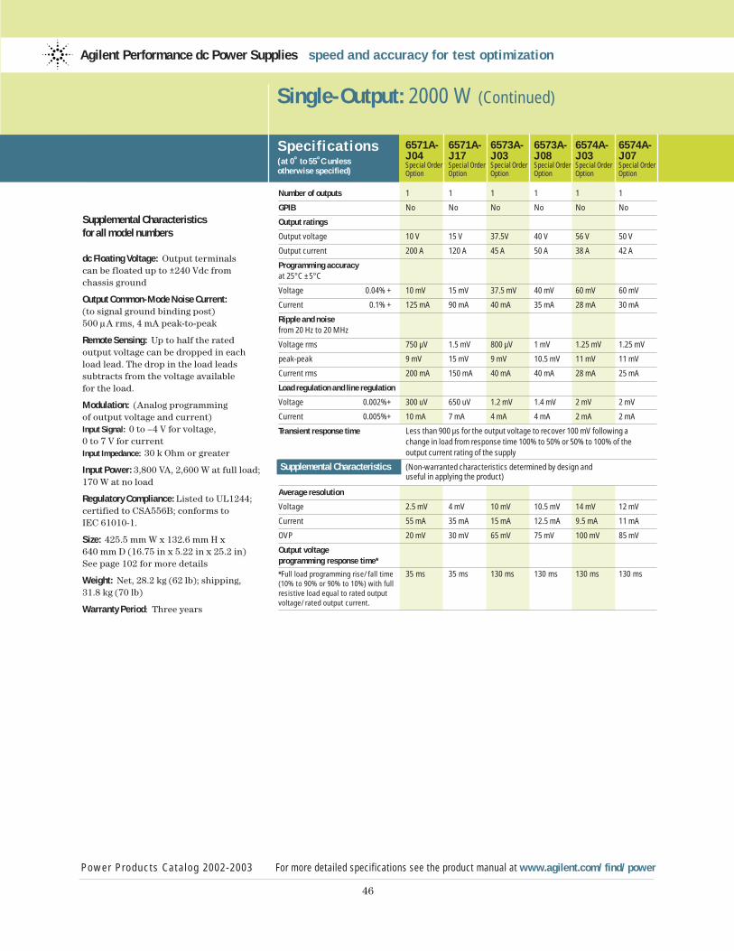
46
Supplemental Characteristicsfor all model numbers
dc Floating Voltage: Output terminals can be floated up to ±240 Vdc from chassis ground
Output Common-Mode Noise Current:(to signal ground binding post)500 µA rms, 4 mA peak-to-peak
Remote Sensing: Up to half the rated output voltage can be dropped in eachload lead. The drop in the load leads subtracts from the voltage available for the load.
Modulation: (Analog programming of output voltage and current)Input Signal: 0 to –4 V for voltage, 0 to 7 V for currentInput Impedance: 30 k Ohm or greater
Input Power: 3,800 VA, 2,600 W at full load;170 W at no load
Regulatory Compliance: Listed to UL1244;certified to CSA556B; conforms to IEC 61010-1.
Size: 425.5 mm W x 132.6 mm H x 640 mm D (16.75 in x 5.22 in x 25.2 in)See page 102 for more details
Weight: Net, 28.2 kg (62 lb); shipping, 31.8 kg (70 lb)
Warranty Period: Three years
Single-Output: 2000 W (Continued)
Specif ications(at 0˚ to 55˚C unless otherwise specified)
Power Products Catalog 2002-2003 For more detailed specifications see the product manual at www.agilent.com/find/power
Agilent Performance dc Power Supplies speed and accuracy for test optimization
6571A- 6571A- 6573A- 6573A- 6574A- 6574A-J04 J17 J03 J08 J03 J07Special Order Special Order Special Order Special Order Special Order Special OrderOption Option Option Option Option Option
Number of outputs 1 1 1 1 1 1
GPIB No No No No No No
Output ratings
Output voltage 10 V 15 V 37.5V 40 V 56 V 50 V
Output current 200 A 120 A 45 A 50 A 38 A 42 A
Programming accuracy at 25°C ±5°C
Voltage 0.04% + 10 mV 15 mV 37.5 mV 40 mV 60 mV 60 mV
Current 0.1% + 125 mA 90 mA 40 mA 35 mA 28 mA 30 mA
Ripple and noise from 20 Hz to 20 MHz
Voltage rms 750 µV 1.5 mV 800 µV 1 mV 1.25 mV 1.25 mV
peak-peak 9 mV 15 mV 9 mV 10.5 mV 11 mV 11 mV
Current rms 200 mA 150 mA 40 mA 40 mA 28 mA 25 mA
Load regulation and line regulation
Voltage 0.002%+ 300 uV 650 uV 1.2 mV 1.4 mV 2 mV 2 mV
Current 0.005%+ 10 mA 7 mA 4 mA 4 mA 2 mA 2 mA
Transient response time Less than 900 µs for the output voltage to recover 100 mV following a change in load from response time 100% to 50% or 50% to 100% of the output current rating of the supply
Supplemental Characteristics (Non-warranted characteristics determined by design and useful in applying the product)
Average resolution
Voltage 2.5 mV 4 mV 10 mV 10.5 mV 14 mV 12 mV
Current 55 mA 35 mA 15 mA 12.5 mA 9.5 mA 11 mA
OVP 20 mV 30 mV 65 mV 75 mV 100 mV 85 mV
Output voltage programming response time*
*Full load programming rise/fall time 35 ms 35 ms 130 ms 130 ms 130 ms 130 ms(10% to 90% or 90% to 10%) with full resistive load equal to rated output voltage/rated output current.
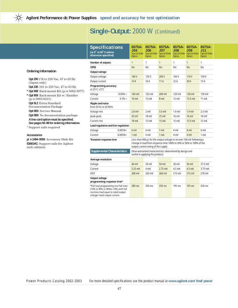
47
Ordering Information
Opt 200 174 to 220 Vac, 47 to 63 Hz (Japan only)Opt 230 191 to 250 Vac, 47 to 63 Hz
* Opt 908 Rack-mount Kit (p/n 5062-3977)* Opt 909 Rack-mount Kit w/ Handles
(p/n 5063-9221)Opt 0L2 Extra Standard Documentation PackageOpt 0B3 Service ManualOpt 0B0 No documentation packageA line cord option must be specified.See pages 93-98 for ordering information.
* Support rails required
Accessoriesp/n 1494-0059 Accessory Slide Kit E3663AC Support rails for Agilent rack cabinets
Single-Output: 2000 W (Continued)
Specif ications(at 0˚ to 55˚C unless otherwise specified)
Power Products Catalog 2002-2003 For more detailed specifications see the product manual at www.agilent.com/find/power
Agilent Performance dc Power Supplies speed and accuracy for test optimization
6575A- 6575A- 6575A- 6575A- 6575A- 6575A-J04 J06 J07 J08 J09 J11Special Order Special Order Special Order Special Order Special Order Special OrderOption Option Option Option Option Option
Number of outputs 1 1 1 1 1 1
GPIB No No No No No No
Output ratings
Output voltage 160 V 135 V 200 V 100 V 110 V 150 V
Output current 13 A 16 A 11 A 22 A 20 A 15 A
Programming accuracy at 25°C ±5°C
Voltage 0.04% + 160 mV 125 mV 200 mV 120 mV 120 mV 150 mV
Current 0.1% + 10 mA 12 mA 8 mA 15 mA 13.5 mA 11 mA
Ripple and noise from 20 Hz to 20 MHz
Voltage rms 2.8 mV 2 mV 3.5 mV 1.9 mV 1.9 mV 2.5 mV
peak-peak 20 mV 18 mV 25 mV 16 mV 16 mV 18 mV
Current rms 18 mA 12 mA 15 mA 15 mA 13.5 mA 12 mA
Load regulation and line regulation
Voltage 0.002%+ 6 mV 4 mV 7 mV 4 mV 4 mV 6 mV
Current 0.005%+ 1 mA 4 mV 1 mA 4 mV 4 mV 1 mA
Transient response time Less than 900 µs for the output voltage to recover 100 mV following a change in load from response time 100% to 50% or 50% to 100% of the output current rating of the supply
Supplemental Characteristics (Non-warranted characteristics determined by design and useful in applying the product)
Average resolution
Voltage 40 mV 34 mV 50 mV 30 mV 30 mV 37.5 mV
Current 3.25 mA 4 mA 2.75 mA 4.5 mA 4.5 mA 3.75 mA
OVP 300 mV 242 mV 360 mV 215 mV 215 mV 270 mV
Output voltage programming response time*
*Full load programming rise/fall time 280 ms 250 ms 350 ms 195 ms 195 ms 250 ms(10% to 90% or 90%to 10%) with full resistive load equal to rated output voltage/rated output current.
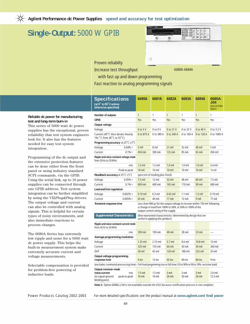
Reliable dc power for manufacturing test and long-term burn-inThis series of 5000 watt dc powersupplies has the exceptional, provenreliability that test system engineerslook for. It also has the featuresneeded for easy test system integration.
Programming of the dc output andthe extensive protection featurescan be done either from the frontpanel or using industry standardSCPI commands, via the GPIB.Using the serial link, up to 16 powersupplies can be connected throughone GPIB address. Test system integration can be further simplifiedby using the VXIPlug&Play drivers. The output voltage and current can also be controlled with analogsignals. This is helpful for certaintypes of noisy environments, andalso immediate reactions to process changes.
The 6680A Series has extremely low ripple and noise for a 5000 wattdc power supply. This helps thebuilt-in measurement system makeextremely accurate current and voltage measurements.
Selectable compensation is providedfor problem-free powering of inductive loads.
Agilent Performance dc Power Supplies speed and accuracy for test optimization
Specif ications(at 0˚ to 55˚C unless otherwise specified)
6680A 6681A 6682A 6683A 6684A 6680A-J04Special OrderOption
Power Products Catalog 2002-2003 For more detailed specifications see the product manual at www.agilent.com/find/power
48
Proven reliabilty
Increase test throughput
with fast up and down programming
Fast reaction to analog programming signals
6680A-6684A
Single-Output: 5000 W GPIB
Number of outputs 1 1 1 1 1 1
GPIB Yes Yes Yes Yes Yes Yes
Output ratings
Voltage 0 to 5 V 0 to 8 V 0 to 21 V 0 to 32 V 0 to 40 V 0 to 3.3 V
Current (40˚C then derate linearly 0 to 875 A 0 to 580 A 0 to 240 A 0 to 160 A 0 to 128 A 0 to 1000 A1%/˚C from 40˚C to 55˚C)
Programming accuracy at 25˚C ±5˚C
Voltage 0.04% + 5 mV 8 mV 21 mV 32 mV 40 mV 5 mV
Current 0.1% + 450 mA 300 mA 125 mA 85 mA 65 mA 450 mV
Ripple and noise constant voltage modefrom 20 Hz to 20 MHz
rms 1.5 mV 1.5 mV 1.0 mV 1.0 mV 1.0 mV 3.4 mV
Peak to peak 10 mV 10 mV 10 mV 10 mV 10 mV 15 mV
Readback accuracy at 25˚C ±5˚C (percent of reading plus fixed)
Voltage 0.05% + 7.5 mV 12 mV 32 mV 48 mV 60 mV 7.5 mV
Current 0.1% + 600 mA 400 mA 165 mA 110 mA 90 mA 600 mA
Load and line regulation
Voltage 0.002% + 0.19 mV 0.3 mV 0.65 mV 1.1 mV 1.5 mV 0.19 mV
Current 0.005% + 65 mA 40 mA 17 mA 12 mA 9 mA 77 mA
Transient response time Less than 900 µs for the output voltage to recover within 150 mV following a change in load from 100% to 50%, or 50% to 100% of the output current rating of the supply
Supplemental Characteristics (Non-warranted characteristics determined by design that are useful in applying this product)
Ripple and noise constant current modefrom 20 Hz to 20 MHz
rms 290 mA 190 mA 40 mA 28 mA 23 mA —
Average programming resolution
Voltage 1.35 mV 2.15 mV 5.7 mV 8.6 mV 10.8 mV 12 mV
Current 235 mA 155 mA 64 mA 43 mA 34 mA 260 mA
OVP 30 mV 45 mV 120 mV 180 mV 225 mV 25 mV
Output voltage programmingresponse time 9 ms 12 ms 45 ms 60 ms 60 ms 9 ms
(excludes command-processing time) Full-load progrmming rise or fall time (10 to 90% or 90 to 10%, resistive load)
Output common-mode noise current rms 1.5 mA 1.5 mA 3 mA 3 mA 3 mA 2.0 mA(to signal-ground peak-to-peak 10 mA 10 mA 20 mA 20 mA 20 mA 12.5 mAbinding post)
Note 1: Option 6680A-JO4 is not available outside the USA because certification process is not complete.
49
Supplemental Characteristicsfor all model numbers
dc Floating Voltage: Output terminals canbe floated up to ±60 Vdc maximum fromchassis ground
Remote Sensing: Up to half the rated output voltage can be dropped in eachload lead. The drop in the load leads subtracts from the voltage available forthe load.
Command Processing Time: Average timerequired for the output voltage to begin to change following receipt of digital datais 20 ms for power supplies connecteddirectly to the GPIB
Modulation: (analog programming of output voltage and current):Input Signal: 0 to –5 V for voltage, 0 to +5 V for currentInput Impedance: 30 kΩ/or greater
ac Input (47 to 63 Hz): 180 to 235 Vac (line-to-line, 3 phase), 27.7 A rms maximum worst case, 21.4 A rms nominal; 360 to 440 Vac, 14.3 A rms maximum worst case, 10.7 A rms nomi-nal (maximum line current includes 5% unbalanced phase voltage condition.)Output voltage derated 5% at 50 Hz and below 200 Vac.
Input Power: 7350 VA and 6000 W maximum; 160 W at no load
GPIB Interface Capabilities: SH1, AH1, T6,L4, SR1, RL1, PP0, DC1, DT1, E1, and C0.IEEE-488.2 and SCPI command set.
Size: 425.5 mm W x 221.5 mm H x 674.7 mm D (16.75 in x 8.75 in x 25.56 in)See page 104 for more details
Weight: Net, 51.3 kg (113 lbs); shipping, 63.6 kg (140 lbs)
Warranty Period: Three years
Ordering Information
Opt 208 180 to 235 Vac, 3 phase, 47 to 63 HzOpt 400 360 to 440 Vac, 3 phase, 47 to 63 HzOpt 602 Two Bus Bar Spacers for paralleling power supplies (p/n 5060-3514)
* Opt 908 Rack-mount Kit (p/n 5062-3977 and p/n 5063-9212)
* Opt 909 Rack-mount Kit with Handles(p/n 5063-9221 and p/n 5063-9219).Opt 0L2 Extra Standard Documentation PackageOpt 0B3 Service Manual Opt 0B0 No Documentation Package
* Support rails required
Accessoriesp/n 5060-3513 Three 30-A ReplacementFuses for 180 to 235 Vac linep/n 5060-3512 Three 16-A ReplacementFuses for 360 to 440 Vac lineE3663AC Support rails for Agilent rack cabinetsp/n 5080-2148 Serial link cable 2m (6.6 ft.)
Single-Output: 5000 W GPIB (Continued)
Power Products Catalog 2002-2003 For more detailed specifications see the product manual at www.agilent.com/find/power
Agilent Performance dc Power Supplies speed and accuracy for test optimization
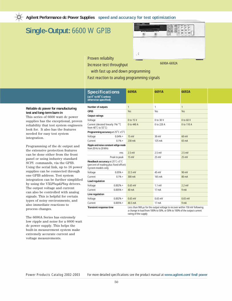
Reliable dc power for manufacturing test and long-term burn-inThis series of 6600 watt dc powersupplies has the exceptional, provenreliability that test system engineerslook for. It also has the featuresneeded for easy test system integration.
Programming of the dc output andthe extensive protection featurescan be done either from the frontpanel or using industry standardSCPI commands, via the GPIB.Using the serial link, up to 16 powersupplies can be connected throughone GPIB address. Test system integration can be further simplifiedby using the VXIPlug&Play drivers.The output voltage and current can also be controlled with analogsignals. This is helpful for certain types of noisy environments, andalso immediate reactions to process changes.
The 6690A Series has extremely low ripple and noise for a 6600 wattdc power supply. This helps thebuilt-in measurement system makeextremely accurate current and voltage measurements.
Agilent Performance dc Power Supplies speed and accuracy for test optimization
Specif ications(at 0˚ to 55˚C unless otherwise specified)
Power Products Catalog 2002-2003 For more detailed specifications see the product manual at www.agilent.com/find/power
50
Proven reliabilty
Increase test throughput
with fast up and down programming
Fast reaction to analog programming signals
6690A-6692A
Single-Output: 6600 W GPIB
6690A 6691A 6692A
Number of outputs 1 1 1
GPIB Yes Yes Yes
Output ratings
Voltage 0 to 15 V 0 to 30 V 0 to 60 V
Current (derated linearly 1%/˚C 0 to 440 A 0 to 220 A 0 to 110 A from 40˚C to 55˚C)
Programming accuracy at 25˚C ±5˚C
Voltage 0.04% + 15 mV 30 mV 60 mV
Current 0.1% + 230 mA 125 mA 65 mA
Ripple and noise constant voltge modefrom 20 Hz to 20 MHz
rms 2.5 mV 2.5 mV 2.5 mV
Peak to peak 15 mV 25 mV 25 mV
Readback accuracy at 25˚C ±5˚C (percent of reading plus fixed offset) System models only
Voltage 0.05% + 22.5 mV 45 mV 90 mV
Current 0.1% + 300 mA 165 mA 80 mA
Load regulation
Voltage 0.002% + 0.65 mV 1.1 mV 2.2 mV
Current 0.005% + 40 mA 17 mA 9 mA
Line regulation
Voltage 0.002% + 0.65 mV 0.65 mV 0.65 mV
Current 0.005% + 40.5 mA 17 mA 9 mA
Transient response time Less than 900 µs for the output voltage to recover within 150 mV following a change in load from 100% to 50%, or 50% to 100% of the output current rating of the supply
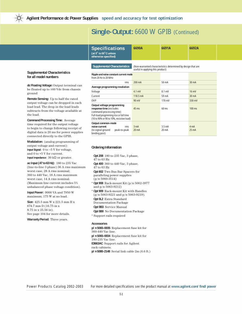
51
Supplemental Characteristicsfor all model numbers
dc Floating Voltage: Output terminal canbe floated up to ±60 Vdc from chassisground
Remote Sensing: Up to half the rated output voltage can be dropped in eachload lead. The drop in the load leadssubtracts from the voltage available atthe load.
Command Processing Time: Average time required for the output voltage to begin to change following receipt ofdigital data is 20 ms for power suppliesconnected directly to the GPIB.
Modulation: (analog programming of output voltage and current):Input Signal: 0 to –5 V for voltage, and 0 to +5 V for current.Input Impedance: 30 kΩ or greater.
ac Input (47 to 63 Hz): 180 to 235 Vac (line-to-line 3 phase) 36 A rms maximumworst case, 28 A rms nominal;360 to 440 Vac, 18 A rms maximum worst case, 14 A rms nominal.(Maximum line current includes 5%unbalanced phase voltage condition).
Input Power: 9000 VA and 7950 W maximum; 175 W at no load.
Size: 425.5 mm W x 221.5 mm H x 674.7 mm D (16.75 in x8.75 in x 25.56 in). See page 104 for more details.
Warranty Period: Three years.
Single-Output: 6600 W GPIB (Continued)
Power Products Catalog 2002-2003 For more detailed specifications see the product manual at www.agilent.com/find/power
Agilent Performance dc Power Supplies speed and accuracy for test optimization
Specif ications(at 0˚ to 55˚C unless otherwise specified)
6690A 6691A 6692A
Supplemental Characteristics (Non-warranted characteristics determined by design that are useful in applying this product)
Ripple and noise constant current modefrom 20 Hz to 20 MHz
rms 200 mA 50 mA 30 mA
Average programming resolution
Voltage 4.1 mV 8.1 mV 16 mV
Current 118.5 mA 59 mA 30 mA
OVP 90 mV 170 mV 330 mV
Output voltage programmingresponse time (excludes 45 ms 60 ms 100 mscommand-processing time)Full-load progrmming rise or fall time(10 to 90% or 90 to 10%, resistive load)
Output common-mode noise current rms 3 mA 3.5 mA 4 mA (to signal-ground peak-to-peak 20 mA 20 mA 25 mAbinding post)
Ordering Information
Opt 208 180 to 235 Vac, 3 phase, 47 to 63 HzOpt 400 360 to 440 Vac, 3 phase, 47 to 63 HzOpt 602 Two Bus Bar Spacers for paralleling power supplies (p/n 5060-3514)
* Opt 908 Rack-mount Kit (p/n 5062-3977and p/n 5063-9212)
* Opt 909 Rack-mount Kit with Handles(p/n 5063-9221 and p/n 5063-9219).Opt 0L2 Extra Standard Documentation PackageOpt 0B3 Service ManualOpt 0B0 No Documentation Package
* Support rails required
Accessoriesp/n 5065-6935 Replacement fuse kit for360-440 Vac line.p/n 5065-6934 Replacement fuse kit for180-235 Vac line.E3663AC Support rails for Agilent rack cabinets.p/n 5080-2148 Serial link cable 2m (6.6 ft.)
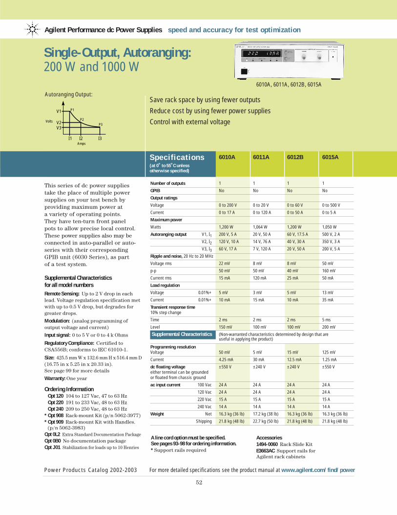
This series of dc power suppliestake the place of multiple powersupplies on your test bench by providing maximum power at a variety of operating points. They have ten-turn front panel pots to allow precise local control.These power supplies also may beconnected in auto-parallel or auto-series with their correspondingGPIB unit (6030 Series), as part of a test system.
Supplemental Characteristicsfor all model numbers
Remote Sensing: Up to 2 V drop in eachlead. Voltage regulation specification metwith up to 0.5 V drop, but degrades forgreater drops.
Modulation: (analog programming of output voltage and current)
Input signal: 0 to 5 V or 0 to 4 k Ohms
Regulatory Compliance: Certified toCSA556B; conforms to IEC 61010-1.
Size: 425.5 mm W x 132.6 mm H x 516.4 mm D(16.75 in x 5.25 in x 20.33 in). See page 99 for more details
Warranty: One year
Ordering InformationOpt 120 104 to 127 Vac, 47 to 63 Hz Opt 220 191 to 233 Vac, 48 to 63 Hz Opt 240 209 to 250 Vac, 48 to 63 Hz
* Opt 908 Rack-mount Kit (p/n 5062-3977)* Opt 909 Rack-mount Kit with Handles.
(p/n 5062-3983)Opt 0L2 Extra Standard Documentation PackageOpt 0B0 No documentation packageOpt J01 Stabilization for loads up to 10 Henries
Agilent Performance dc Power Supplies speed and accuracy for test optimization
Specif ications(at 0˚ to 55˚C unless otherwise specified)
Power Products Catalog 2002-2003 For more detailed specifications see the product manual at www.agilent.com/find/power
52
Save rack space by using fewer outputs
Reduce cost by using fewer power supplies
Control with external voltage
6010A, 6011A, 6012B, 6015A
Single-Output, Autoranging:200 W and 1000 W
6010A 6011A 6012B 6015A
Number of outputs 1 1 1 1
GPIB No No No No
Output ratings
Voltage 0 to 200 V 0 to 20 V 0 to 60 V 0 to 500 V
Current 0 to 17 A 0 to 120 A 0 to 50 A 0 to 5 A
Maximum power
Watts 1,200 W 1,064 W 1,200 W 1,050 W
Autoranging output V1, I1 200 V, 5 A 20 V, 50 A 60 V, 17.5 A 500 V, 2 A
V2, I2 120 V, 10 A 14 V, 76 A 40 V, 30 A 350 V, 3 A
V3, I3 60 V, 17 A 7 V, 120 A 20 V, 50 A 200 V, 5 A
Ripple and noise, 20 Hz to 20 MHz
Voltage rms 22 mV 8 mV 8 mV 50 mV
p-p 50 mV 50 mV 40 mV 160 mV
Current rms 15 mA 120 mA 25 mA 50 mA
Load regulation
Voltage 0.01%+ 5 mV 3 mV 5 mV 13 mV
Current 0.01%+ 10 mA 15 mA 10 mA 35 mA
Transient response time10% step change
Time 2 ms 2 ms 2 ms 5 ms
Level 150 mV 100 mV 100 mV 200 mV
Supplemental Characteristics (Non-warranted characteristics determined by design that are useful in applying the product)
Programming resolution Voltage 50 mV 5 mV 15 mV 125 mV
Current 4.25 mA 30 mA 12.5 mA 1.25 mA
dc floating voltage ±550 V ±240 V ±240 V ±550 Veither terminal can be groundedor floated from chassis ground
ac input current 100 Vac 24 A 24 A 24 A 24 A
120 Vac 24 A 24 A 24 A 24 A
220 Vac 15 A 15 A 15 A 15 A
240 Vac 14 A 14 A 14 A 14 A
Weight Net 16.3 kg (36 lb) 17.2 kg (38 lb) 16.3 kg (36 lb) 16.3 kg (36 lb)
Shipping 21.8 kg (48 lb) 22.7 kg (50 lb) 21.8 kg (48 lb) 21.8 kg (48 lb)
A line cord option must be specified.See pages 93-98 for ordering information.* Support rails required
Accessories1494-0060 Rack Slide KitE3663AC Support rails for Agilent rack cabinets
V1
I1 I2 I3
Volts
P1
P2P3
Amps
V2V3
Autoranging Output:
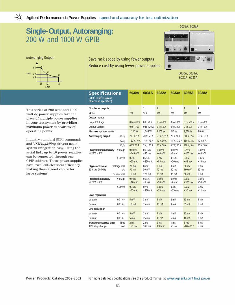
This series of 200 watt and 1000watt dc power supplies take theplace of multiple power supplies in your test system by providingmaximum power at a variety ofoperating points.
Industry standard SCPI commandsand VXIPlug&Play drivers makesystem integration easy. Using theserial link, up to 16 power suppliescan be connected through one GPIB address. These power supplieshave excellent electrical efficiency,making them a good choice for large systems.
Agilent Performance dc Power Supplies speed and accuracy for test optimization
Specif ications(at 0˚ to 55˚C unless otherwise specified)
6030A 6031A 6032A 6033A 6035A 6038A
Power Products Catalog 2002-2003 For more detailed specifications see the product manual at www.agilent.com/find/power
53
Save rack space by using fewer outputs
Reduce cost by using fewer power supplies
6030A, 6031A, 6032A, 6035A
6033A, 6038A
Single-Output, Autoranging: 200 W and 1000 W GPIB
Number of outputs 1 1 1 1 1 1
GPIB Yes Yes Yes Yes Yes Yes
Output ratings
Output Voltage 0 to 200 V 0 to 20 V 0 to 60 V 0 to 20 V 0 to 500 V 0 to 60 V
Output Current 0 to 17 A 0 to 120 A 0 to 50 A 0 to 30 A 0 to 5 A 0 to 10 A
Maximum power watts 1,200 W 1,064 W 1,200 W 242 W 1,050 W 240 W
Autoranging output V1, I1 200 V, 5 A 20 V, 50 A 60 V, 17.5 A 20 V, 10 A 500 V, 2 A 60 V, 3.3 A
V2, I2 120 V, 10 A 14 V, 76 A 40 V, 30 A 14 V, 17.2 A 350 V, 3 A 40 V, 6 A
V3, I3 60 V, 17 A 7 V, 120 A 20 V, 50 A 6.7 V, 30 A 200 V, 5 A 20 V, 10 A
Programming accuracy Voltage 0.035% 0.035% 0.035% 0.035% 0.25% 0.035% at 25°C ±5°C +145 mV +15 mV +40 mV +9 mV +400 mV +40 mV
Current 0.2% 0.25% 0.2% 0.15% 0.3% 0.09% +25 mA +250 mA +85 mA +20 mA +63 mA +10 mA
Ripple and noise Voltage rms 22 mV 8 mV 8 mV 3 mV 50 mV 3 mV20 Hz to 20 MHz p-p 50 mV 50 mV 40 mV 30 mV 160 mV 30 mV
Current rms 15 mA 120 mA 25 mA 30 mA 50 mA 5 mA
Readback accuracy Voltage 0.08% 0.08% 0.08% 0.07% 0.5% 0.07% at 25°C ±5°C +80 mV +7 mV +20 mV +6 mV +300 mV +50 mV
Current 0.36% 0.4% 0.36% 0.3% 0.5% 0.2% +15 mA +100 mA +35 mA +25 mA +50 mA +11 mA
Load regulation
Voltage 0.01%+ 5 mV 3 mV 5 mV 2 mV 13 mV 3 mV
Current 0.01%+ 10 mA 15 mA 10 mA 9 mA 35 mA 5 mA
Line regulation
Voltage 0.01%+ 5 mV 2 mV 3 mV 1 mV 13 mV 2 mV
Current 0.01%+ 5 mA 25 mA 10 mA 6 mA 18 mA 2 mA
Transient response time Time 2 ms 2 ms 2 ms 1 ms 5 ms 1 ms10% step change Level 150 mV 100 mV 100 mV 50 mV 200 mV 7 5 mV
V1
I1 I2 I3
Volts
P1
P2P3
Amps
V2V3
Autoranging Output:
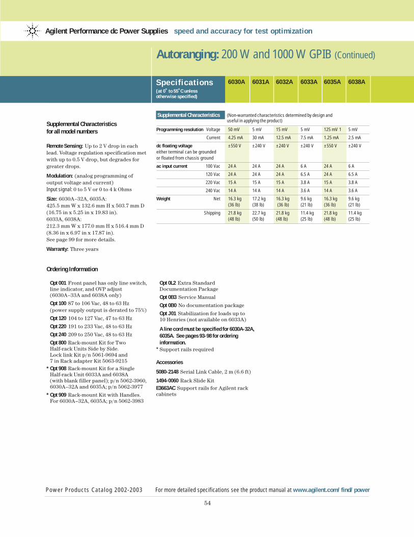
54
Supplemental Characteristicsfor all model numbers
Remote Sensing: Up to 2 V drop in eachlead. Voltage regulation specification metwith up to 0.5 V drop, but degrades forgreater drops.
Modulation: (analog programming of output voltage and current)Input signal: 0 to 5 V or 0 to 4 k Ohms
Size: 6030A–32A, 6035A: 425.5 mm W x 132.6 mm H x 503.7 mm D (16.75 in x 5.25 in x 19.83 in).6033A, 6038A: 212.3 mm W x 177.0 mm H x 516.4 mm D(8.36 in x 6.97 in x 17.87 in).See page 99 for more details.
Warranty: Three years
Ordering Information
Opt 001 Front panel has only line switch, line indicator, and OVP adjust (6030A–33A and 6038A only)
Opt 100 87 to 106 Vac, 48 to 63 Hz (power supply output is derated to 75%)
Opt 120 104 to 127 Vac, 47 to 63 Hz
Opt 220 191 to 233 Vac, 48 to 63 Hz
Opt 240 209 to 250 Vac, 48 to 63 Hz
Opt 800 Rack-mount Kit for Two Half-rack Units Side by Side. Lock link Kit p/n 5061-9694 and 7 in Rack adapter Kit 5063-9215
* Opt 908 Rack-mount Kit for a Single Half-rack Unit 6033A and 6038A (with blank filler panel); p/n 5062-3960, 6030A–32A and 6035A; p/n 5062-3977
* Opt 909 Rack-mount Kit with Handles.For 6030A–32A, 6035A; p/n 5062-3983
Autoranging: 200 W and 1000 W GPIB (Continued)
Power Products Catalog 2002-2003 For more detailed specifications see the product manual at www.agilent.com/find/power
Agilent Performance dc Power Supplies speed and accuracy for test optimization
Specif ications(at 0˚ to 55˚C unless otherwise specified)
6030A 6031A 6032A 6033A 6035A 6038A
Supplemental Characteristics (Non-warranted characteristics determined by design and useful in applying the product)
Programming resolution Voltage 50 mV 5 mV 15 mV 5 mV 125 mV 1 5 mV
Current 4.25 mA 30 mA 12.5 mA 7.5 mA 1.25 mA 2.5 mA
dc floating voltage ±550 V ±240 V ±240 V ±240 V ±550 V ±240 Veither terminal can be groundedor floated from chassis ground
ac input current 100 Vac 24 A 24 A 24 A 6 A 24 A 6 A
120 Vac 24 A 24 A 24 A 6.5 A 24 A 6.5 A
220 Vac 15 A 15 A 15 A 3.8 A 15 A 3.8 A
240 Vac 14 A 14 A 14 A 3.6 A 14 A 3.6 A
Weight Net 16.3 kg 17.2 kg 16.3 kg 9.6 kg 16.3 kg 9.6 kg (36 lb) (38 lb) (36 lb) (21 lb) (36 lb) (21 lb)
Shipping 21.8 kg 22.7 kg 21.8 kg 11.4 kg 21.8 kg 11.4 kg (48 lb) (50 lb) (48 lb) (25 lb) (48 lb) (25 lb)
Opt 0L2 Extra Standard Documentation Package
Opt 0B3 Service Manual
Opt 0B0 No documentation package
Opt J01 Stabilization for loads up to 10 Henries (not available on 6033A)
A line cord must be specified for 6030A-32A, 6035A. See pages 93-98 for ordering information.
* Support rails required
Accessories
5080-2148 Serial Link Cable, 2 m (6.6 ft)
1494-0060 Rack Slide KitE3663AC Support rails for Agilent rack cabinets
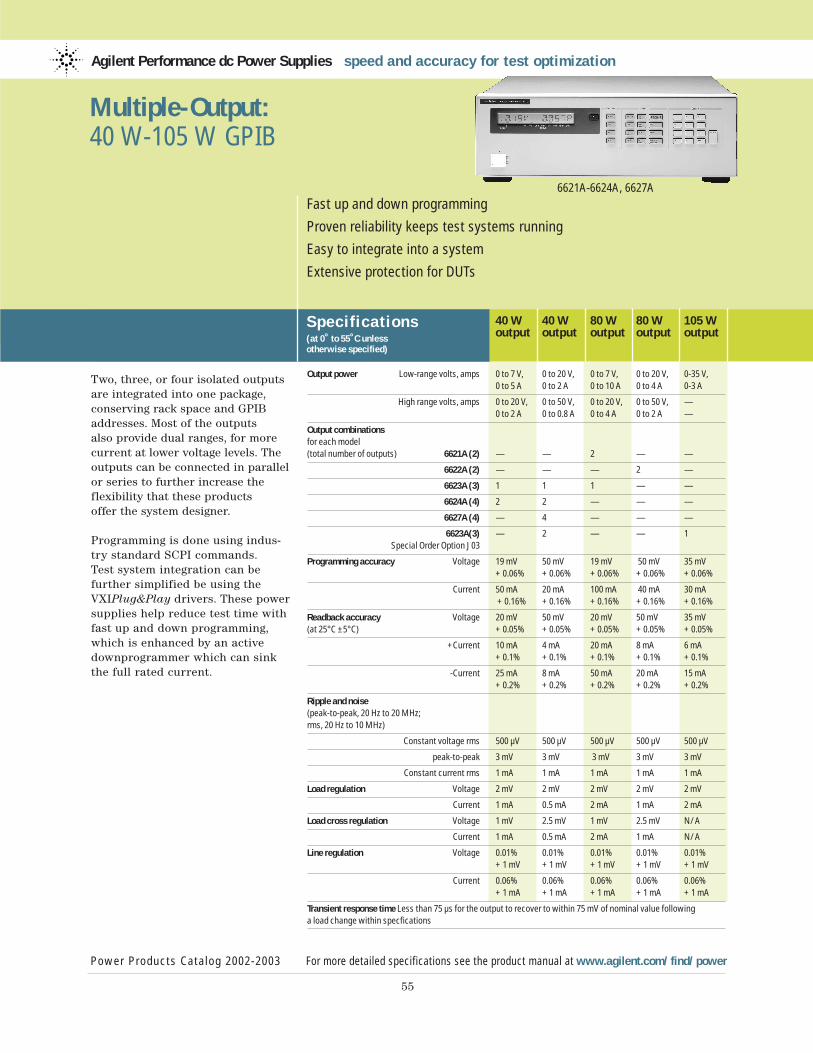
Two, three, or four isolated outputsare integrated into one package,conserving rack space and GPIBaddresses. Most of the outputs also provide dual ranges, for morecurrent at lower voltage levels. Theoutputs can be connected in parallelor series to further increase theflexibility that these products offer the system designer.
Programming is done using indus-try standard SCPI commands. Test system integration can be further simplified be using theVXIPlug&Play drivers. These powersupplies help reduce test time withfast up and down programming,which is enhanced by an activedownprogrammer which can sinkthe full rated current.
Agilent Performance dc Power Supplies speed and accuracy for test optimization
Specif ications(at 0˚ to 55˚C unless otherwise specified)
40 W 40 W 80 W 80 W 105 Woutput output output output output
Power Products Catalog 2002-2003 For more detailed specifications see the product manual at www.agilent.com/find/power
55
Fast up and down programming
Proven reliability keeps test systems running
Easy to integrate into a system
Extensive protection for DUTs
6621A-6624A, 6627A
Multiple-Output: 40 W-105 W GPIB
Output power Low-range volts, amps 0 to 7 V, 0 to 20 V, 0 to 7 V, 0 to 20 V, 0-35 V,0 to 5 A 0 to 2 A 0 to 10 A 0 to 4 A 0-3 A
High range volts, amps 0 to 20 V, 0 to 50 V, 0 to 20 V, 0 to 50 V, —0 to 2 A 0 to 0.8 A 0 to 4 A 0 to 2 A —
Output combinationsfor each model (total number of outputs) 6621A (2) — — 2 — —
6622A (2) — — — 2 —
6623A (3) 1 1 1 — —
6624A (4) 2 2 — — —
6627A (4) — 4 — — —
6623A(3) — 2 — — 1Special Order Option J03
Programming accuracy Voltage 19 mV 50 mV 19 mV 50 mV 35 mV+ 0.06% + 0.06% + 0.06% + 0.06% + 0.06%
Current 50 mA 20 mA 100 mA 40 mA 30 mA+ 0.16% + 0.16% + 0.16% + 0.16% + 0.16%
Readback accuracy Voltage 20 mV 50 mV 20 mV 50 mV 35 mV(at 25°C ±5°C) + 0.05% + 0.05% + 0.05% + 0.05% + 0.05%
+Current 10 mA 4 mA 20 mA 8 mA 6 mA+ 0.1% + 0.1% + 0.1% + 0.1% + 0.1%
-Current 25 mA 8 mA 50 mA 20 mA 15 mA+ 0.2% + 0.2% + 0.2% + 0.2% + 0.2%
Ripple and noise (peak-to-peak, 20 Hz to 20 MHz; rms, 20 Hz to 10 MHz)
Constant voltage rms 500 µV 500 µV 500 µV 500 µV 500 µV
peak-to-peak 3 mV 3 mV 3 mV 3 mV 3 mV
Constant current rms 1 mA 1 mA 1 mA 1 mA 1 mA
Load regulation Voltage 2 mV 2 mV 2 mV 2 mV 2 mV
Current 1 mA 0.5 mA 2 mA 1 mA 2 mA
Load cross regulation Voltage 1 mV 2.5 mV 1 mV 2.5 mV N/A
Current 1 mA 0.5 mA 2 mA 1 mA N/A
Line regulation Voltage 0.01% 0.01% 0.01% 0.01% 0.01%+ 1 mV + 1 mV + 1 mV + 1 mV + 1 mV
Current 0.06% 0.06% 0.06% 0.06% 0.06%+ 1 mA + 1 mA + 1 mA + 1 mA + 1 mA
Transient response time Less than 75 µs for the output to recover to within 75 mV of nominal value following a load change within specfications
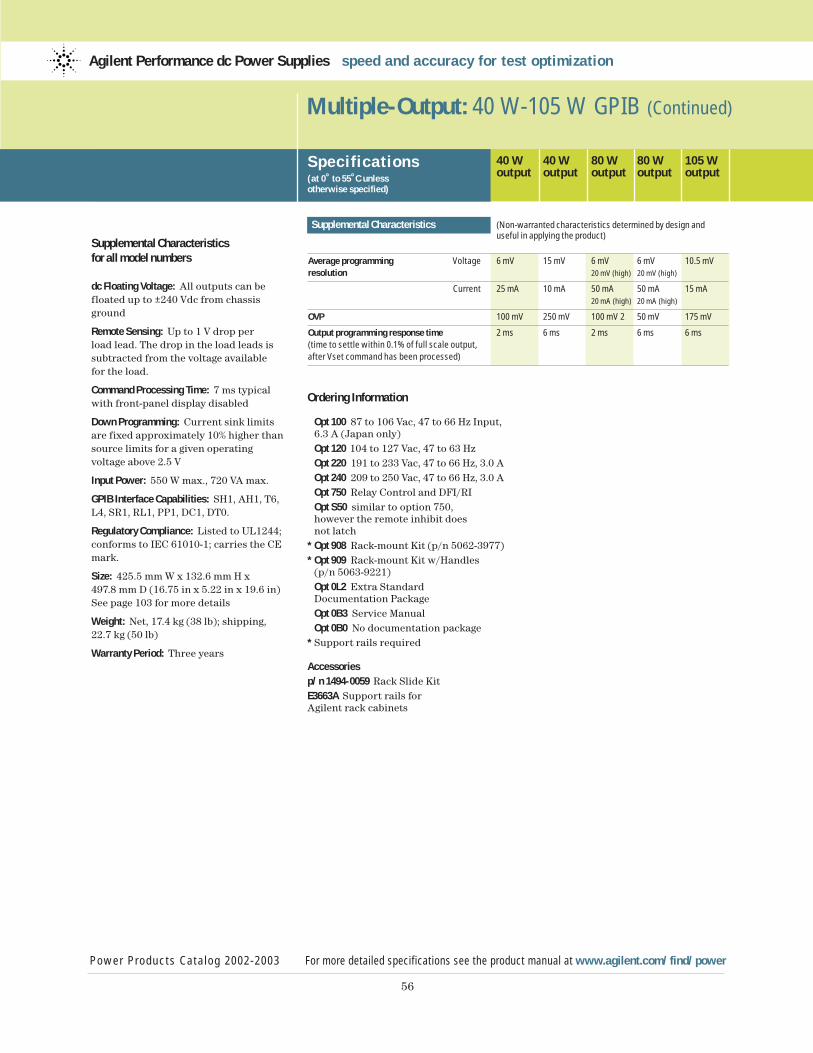
56
Supplemental Characteristicsfor all model numbers
dc Floating Voltage: All outputs can be floated up to ±240 Vdc from chassisground
Remote Sensing: Up to 1 V drop per load lead. The drop in the load leads issubtracted from the voltage available for the load.
Command Processing Time: 7 ms typicalwith front-panel display disabled
Down Programming: Current sink limits are fixed approximately 10% higher thansource limits for a given operatingvoltage above 2.5 V
Input Power: 550 W max., 720 VA max.
GPIB Interface Capabilities: SH1, AH1, T6,L4, SR1, RL1, PP1, DC1, DT0.
Regulatory Compliance: Listed to UL1244;conforms to IEC 61010-1; carries the CEmark.
Size: 425.5 mm W x 132.6 mm H x 497.8 mm D (16.75 in x 5.22 in x 19.6 in)See page 103 for more details
Weight: Net, 17.4 kg (38 lb); shipping, 22.7 kg (50 lb)
Warranty Period: Three years
Multiple-Output: 40 W-105 W GPIB (Continued)
Specif ications(at 0˚ to 55˚C unless otherwise specified)
40 W 40 W 80 W 80 W 105 Woutput output output output output
Supplemental Characteristics (Non-warranted characteristics determined by design and useful in applying the product)
Average programming Voltage 6 mV 15 mV 6 mV 6 mV 10.5 mVresolution 20 mV (high) 20 mV (high)
Current 25 mA 10 mA 50 mA 50 mA 15 mA20 mA (high) 20 mA (high)
OVP 100 mV 250 mV 100 mV 2 50 mV 175 mV
Output programming response time 2 ms 6 ms 2 ms 6 ms 6 ms(time to settle within 0.1% of full scale output, after Vset command has been processed)
Power Products Catalog 2002-2003 For more detailed specifications see the product manual at www.agilent.com/find/power
Agilent Performance dc Power Supplies speed and accuracy for test optimization
Ordering Information
Opt 100 87 to 106 Vac, 47 to 66 Hz Input,6.3 A (Japan only) Opt 120 104 to 127 Vac, 47 to 63 HzOpt 220 191 to 233 Vac, 47 to 66 Hz, 3.0 A Opt 240 209 to 250 Vac, 47 to 66 Hz, 3.0 A Opt 750 Relay Control and DFI/RI Opt S50 similar to option 750, however the remote inhibit does not latch
* Opt 908 Rack-mount Kit (p/n 5062-3977)* Opt 909 Rack-mount Kit w/Handles
(p/n 5063-9221) Opt 0L2 Extra Standard Documentation PackageOpt 0B3 Service ManualOpt 0B0 No documentation package
* Support rails required
Accessoriesp/n 1494-0059 Rack Slide KitE3663A Support rails for Agilent rack cabinets
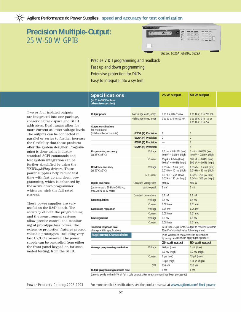
Two or four isolated outputs are integrated into one package,conserving rack space and GPIBaddresses. Dual ranges allow formore current at lower voltage levels.The outputs can be connected inparallel or series to further increasethe flexibility that these productsoffer the system designer. Program-ming is done using industry standard SCPI commands and test system integration can be further simplified be using theVXIPlug&Play drivers. These power supplies help reduce testtime with fast up and down pro-gramming, which is enhanced by the active down-programmer which can sink the full rated current.
These power supplies are very useful on the R&D bench. The accuracy of both the programmingand the measurement systems allow precise control and monitor-ing of prototype bias power. Theextensive protection features protectvaluable prototypes, including veryfast CV/CC crossover. The powersupply can be controlled from eitherthe front panel keypad or, for auto-mated testing, from the GPIB.
Agilent Performance dc Power Supplies speed and accuracy for test optimization
Specif ications(at 0˚ to 55˚C unless otherwise specified)
25 W output 50 W output
Power Products Catalog 2002-2003 For more detailed specifications see the product manual at www.agilent.com/find/power
57
Precise V & I programming and readback
Fast up and down programming
Extensive protection for DUTs
Easy to integrate into a system
6625A, 6626A, 6628A, 6629A
Precision Multiple-Output:25 W-50 W GPIB
Output power Low-range volts, amps 0 to 7 V, 0 to 15 mA 0 to 16 V, 0 to 200 mA
High range volts, amps 0 to 50 V, 0 to 500 mA 0 to 50 V, 0 to 1 A or0 to 16 V, 0 to 2 A
Output combinations for each model (total number of outputs) 6625A (2) Precision 1 1
6626A (4) Precision 2 2
6628A (2) Precision — 2
6629A (4) Precision — 4
Programming accuracy Voltage 1.5 mV + 0.016% (low) 3 mV + 0.016% (low)(at 25°C ±5°C) 10 mV + 0.016% (high) 10 mV + 0.016% (high)
Current 15 µA + 0.04% (low) 185 µA + 0.04% (low)100 µA + 0.04% (high) 500 µA + 0.04% (high)
Readback accuracy Voltage 0.016% + 2 mV (low) 0.016% + 3.5 mV (low)(at 25°C ±5°C) 0.016% + 10 mV (high) 0.016% + 10 mV (high)
+/-Current 0.03% + 15 µA (low) 0.04% + 250 µA (low)0.03% + 130 µA (high) 0.04% + 550 µA (high)
Ripple and noise Constant voltage rms 500 µV 500 µV
(peak-to-peak, 20 Hz to 20 MHz; peak-to-peak 3 mV 3 mVrms, 20 Hz to 10 MHz)
Constant current rms 0.1 mA 0.1 mA
Load regulation Voltage 0.5 mV 0.5 mV
Current 0.005 mA 0.01 mA
Load cross regulation Voltage 0.25 mV 0.25 mV
Current 0.005 mA 0.01 mA
Line regulation Voltage 0.5 mV 0.5 mV
Current 0.005 mA 0.01 mA
Transient response time Less than 75 µs for the output to recover to within change within specfications 75 mV of nominal value following a load
Supplemental Characteristics (Non-warranted characteristics determined by design and useful in applying the product)
25-watt output 50-watt outputAverage programming resolution Voltage 460 µV (low) 1 mV (low)
3.2 mV (high) 3.2 mV (high)
Current 1 µA (low) 13 µA (low)
33 µA (high) 131 µA (high)
OVP 230 mV 230 mV
Output programming response time 6 ms 6 ms
(time to settle within 0.1% of full scale output, after Vset command has been processed)
58
Supplemental Characteristicsfor all model numbers
dc Floating Voltage: All outputs can befloated up to ±240 Vdc from chassisground
Remote Sensing: Up to 10 V drop per load lead. The drop in the load leads issubtracted from the voltage available for the load.
Command Processing Time: 7 ms typicalwith front-panel display disabled
Input Power: 550 W max., 720 VA max.
GPIB Interface Capabilities: SH1, AH1, T6,L4, SR1, RL1, PP1, DC1, DT0, C0, E1.
Regulatory Compliance: Listed to UL 1244; conforms to IEC 61010-1.
Size: 425.5 mm W x 132.6 mm H x 497.8 mm D (16.75 in x 5.22 in x 19.6 in) See page 103 for more details
Weight: 6626A, 6629A: Net, 17.4 kg (38 lb); shipping, 22.7 kg (50 lb) 6625A, 6628A:Net, 15.5 kg (34 lb); shipping, 20.8 kg (46 lb)
Warranty Period: Three years
Precision Multiple-Output: 25 W-50 W GPIB (Continued)
Power Products Catalog 2002-2003 For more detailed specifications see the product manual at www.agilent.com/find/power
Agilent Performance dc Power Supplies speed and accuracy for test optimization
Ordering Information
Opt 100 87 to 106 Vac, 47 to 66 Hz Input, 6.3 A (Japan only)Opt 120 104 to 127 Vac, 47 to 63 HzOpt 220 191 to 233 Vac, 47 to 66 Hz, 3.0 AOpt 240 209 to 250 Vac, 47 to 66 Hz, 3.0 AOpt 750 Relay Control and DFI/RIOpt S50 Similar to option 750, howeverthe remote inhibit does not latch
* Opt 908 Rack-mount Kit (p/n 5062-3977) * Opt 909 Rack-mount Kit w/Handles
(p/n 5063-9221)Opt 0L2 Extra Standard Documentation PackageOpt 0B3 Service ManualOpt 0B0 No documentation package
* Support rails required
Accessoriesp/n 1494-0059 Rack Slide KitE3663AC Support rails for Agilent rack cabinets
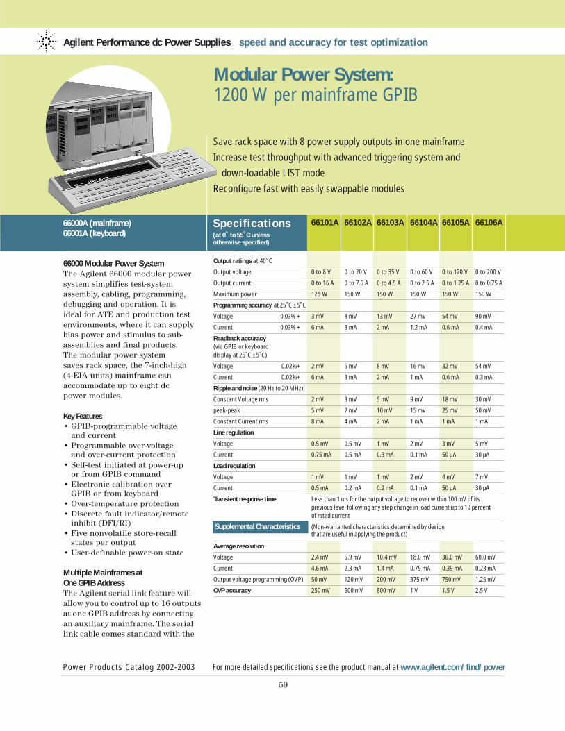
66000 Modular Power SystemThe Agilent 66000 modular powersystem simplifies test-systemassembly, cabling, programming,debugging and operation. It isideal for ATE and production testenvironments, where it can supplybias power and stimulus to sub-assemblies and final products.The modular power system saves rack space, the 7-inch-high (4-EIA units) mainframe can accommodate up to eight dc power modules.
Key Features• GPIB-programmable voltage
and current• Programmable over-voltage
and over-current protection• Self-test initiated at power-up
or from GPIB command• Electronic calibration over
GPIB or from keyboard• Over-temperature protection• Discrete fault indicator/remote
inhibit (DFI/RI)• Five nonvolatile store-recall
states per output• User-definable power-on state
Multiple Mainframes at One GPIB AddressThe Agilent serial link feature willallow you to control up to 16 outputsat one GPIB address by connectingan auxiliary mainframe. The seriallink cable comes standard with the
Agilent Performance dc Power Supplies speed and accuracy for test optimization
Specif ications(at 0˚ to 55˚C unless otherwise specified)
66101A 66102A 66103A 66104A 66105A 66106A
Power Products Catalog 2002-2003 For more detailed specifications see the product manual at www.agilent.com/find/power
59
Save rack space with 8 power supply outputs in one mainframe
Increase test throughput with advanced triggering system and
down-loadable LIST mode
Reconfigure fast with easily swappable modules
66000A (mainframe)66001A (keyboard)
Modular Power System: 1200 W per mainframe GPIB
Output ratings at 40˚C
Output voltage 0 to 8 V 0 to 20 V 0 to 35 V 0 to 60 V 0 to 120 V 0 to 200 V
Output current 0 to 16 A 0 to 7.5 A 0 to 4.5 A 0 to 2.5 A 0 to 1.25 A 0 to 0.75 A
Maximum power 128 W 150 W 150 W 150 W 150 W 150 W
Programming accuracy at 25˚C ±5˚C
Voltage 0.03% + 3 mV 8 mV 13 mV 27 mV 54 mV 90 mV
Current 0.03% + 6 mA 3 mA 2 mA 1.2 mA 0.6 mA 0.4 mA
Readback accuracy (via GPIB or keyboard display at 25˚C ±5˚C)
Voltage 0.02%+ 2 mV 5 mV 8 mV 16 mV 32 mV 54 mV
Current 0.02%+ 6 mA 3 mA 2 mA 1 mA 0.6 mA 0.3 mA
Ripple and noise (20 Hz to 20 MHz)
Constant Voltage rms 2 mV 3 mV 5 mV 9 mV 18 mV 30 mV
peak-peak 5 mV 7 mV 10 mV 15 mV 25 mV 50 mV
Constant Current rms 8 mA 4 mA 2 mA 1 mA 1 mA 1 mA
Line regulation
Voltage 0.5 mV 0.5 mV 1 mV 2 mV 3 mV 5 mV
Current 0.75 mA 0.5 mA 0.3 mA 0.1 mA 50 µA 30 µA
Load regulation
Voltage 1 mV 1 mV 1 mV 2 mV 4 mV 7 mV
Current 0.5 mA 0.2 mA 0.2 mA 0.1 mA 50 µA 30 µA
Transient response time Less than 1 ms for the output voltage to recover within 100 mV of its previous level following any step change in load current up to 10 percent of rated current
Supplemental Characteristics (Non-warranted characteristics determined by design that are useful in applying the product)
Average resolution
Voltage 2.4 mV 5.9 mV 10.4 mV 18.0 mV 36.0 mV 60.0 mV
Current 4.6 mA 2.3 mA 1.4 mA 0.75 mA 0.39 mA 0.23 mA
Output voltage programming (OVP) 50 mV 120 mV 200 mV 375 mV 750 mV 1.25 mV
OVP accuracy 250 mV 500 mV 800 mV 1 V 1.5 V 2.5 V
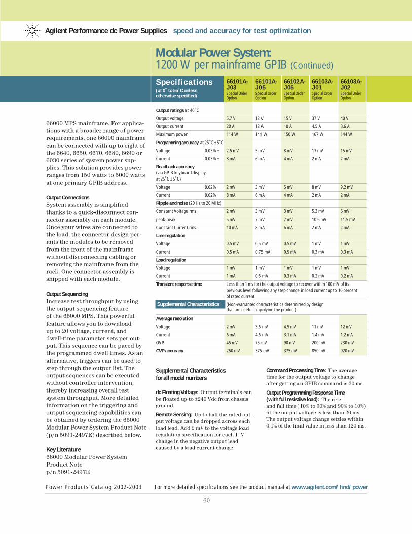
60
66000 MPS mainframe. For applica-tions with a broader range of powerrequirements, one 66000 mainframecan be connected with up to eight of the 6640, 6650, 6670, 6680, 6690 or6030 series of system power sup-plies. This solution provides powerranges from 150 watts to 5000 wattsat one primary GPIB address.
Output ConnectionsSystem assembly is simplifiedthanks to a quick-disconnect con-nector assembly on each module.Once your wires are connected tothe load, the connector design per-mits the modules to be removedfrom the front of the mainframewithout disconnecting cabling orremoving the mainframe from therack. One connector assembly isshipped with each module.
Output SequencingIncrease test throughput by usingthe output sequencing featureof the 66000 MPS. This powerful feature allows you to downloadup to 20 voltage, current, and dwell-time parameter sets per out-put. This sequence can be paced bythe programmed dwell times. As analternative, triggers can be used tostep through the output list. The output sequences can be executedwithout controller intervention,thereby increasing overall test system throughput. More detailedinformation on the triggering andoutput sequencing capabilities canbe obtained by ordering the 66000Modular Power System Product Note(p/n 5091-2497E) described below.
Key Literature66000 Modular Power SystemProduct Notep/n 5091-2497E
Modular Power System: 1200 W per mainframe GPIB (Continued)
Specif ications(at 0˚ to 55˚C unless otherwise specified)
66101A- 66101A- 66102A- 66103A- 66103A-J03 J05 J05 J01 J02Special Order Special Order Special Order Special Order Special OrderOption Option Option Option Option
Output ratings at 40˚C
Output voltage 5.7 V 12 V 15 V 37 V 40 V
Output current 20 A 12 A 10 A 4.5 A 3.6 A
Maximum power 114 W 144 W 150 W 167 W 144 W
Programming accuracy at 25˚C ±5˚C
Voltage 0.03% + 2.5 mV 5 mV 8 mV 13 mV 15 mV
Current 0.03% + 8 mA 6 mA 4 mA 2 mA 2 mA
Readback accuracy(via GPIB keyboard display at 25˚C ±5˚C)
Voltage 0.02% + 2 mV 3 mV 5 mV 8 mV 9.2 mV
Current 0.02% + 8 mA 6 mA 4 mA 2 mA 2 mA
Ripple and noise (20 Hz to 20 MHz)
Constant Voltage rms 2 mV 3 mV 3 mV 5.3 mV 6 mV
peak-peak 5 mV 7 mV 7 mV 10.6 mV 11.5 mV
Constant Current rms 10 mA 8 mA 6 mA 2 mA 2 mA
Line regulation
Voltage 0.5 mV 0.5 mV 0.5 mV 1 mV 1 mV
Current 0.5 mA 0.75 mA 0.5 mA 0.3 mA 0.3 mA
Load regulation
Voltage 1 mV 1 mV 1 mV 1 mV 1 mV
Current 1 mA 0.5 mA 0.3 mA 0.2 mA 0.2 mA
Transient response time Less than 1 ms for the output voltage to recover within 100 mV of its previous level following any step change in load current up to 10 percent of rated current
Supplemental Characteristics (Non-warranted characteristics determined by design that are useful in applying the product)
Average resolution
Voltage 2 mV 3.6 mV 4.5 mV 11 mV 12 mV
Current 6 mA 4.6 mA 3.1 mA 1.4 mA 1.2 mA
OVP 45 mV 75 mV 90 mV 200 mV 230 mV
OVP accuracy 250 mV 375 mV 375 mV 850 mV 920 mV
Power Products Catalog 2002-2003 For more detailed specifications see the product manual at www.agilent.com/find/power
Agilent Performance dc Power Supplies speed and accuracy for test optimization
Supplemental Characteristicsfor all model numbers
dc Floating Voltage: Output terminals canbe floated up to ±240 Vdc from chassisground
Remote Sensing: Up to half the rated out-put voltage can be dropped across eachload lead. Add 2 mV to the voltage loadregulation specification for each 1–Vchange in the negative output leadcaused by a load current change.
Command Processing Time: The averagetime for the output voltage to changeafter getting an GPIB command is 20 ms
Output Programming Response Time (with full resistive load): The riseand fall time (10% to 90% and 90% to 10%)of the output voltage is less than 20 ms.The output voltage change settles within0.1% of the final value in less than 120 ms.
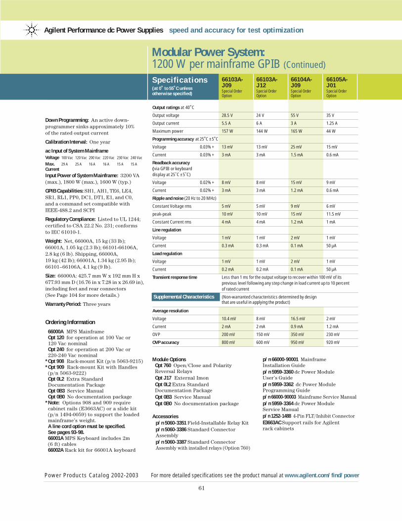
61
Down Programming: An active down-programmer sinks approximately 10% of the rated output current
Calibration Interval: One year
ac Input of System MainframeVoltage 100 Vac 120 Vac 200 Vac 220 Vac 230 Vac 240 Vac
Max. 29 A 25 A 16 A 16 A 15 A 15 ACurrent
Input Power of System Mainframe: 3200 VA(max.), 1800 W (max.), 1600 W (typ.)
GPIB Capabilities: SH1, AH1, TE6, LE4,SR1, RL1, PP0, DC1, DT1, E1, and C0, and a command set compatible withIEEE-488.2 and SCPI
Regulatory Compliance: Listed to UL 1244;certified to CSA 22.2 No. 231; conforms to IEC 61010-1.
Weight: Net, 66000A, 15 kg (33 lb);66001A, 1.05 kg (2.3 lb); 66101-66106A,2.8 kg (6 lb). Shipping, 66000A, 19 kg (42 lb); 66001A, 1.34 kg (2.95 lb);66101–66106A, 4.1 kg (9 lb).
Size: 66000A: 425.7 mm W x 192 mm H x677.93 mm D (16.76 in x 7.28 in x 26.69 in),including feet and rear connectors(See Page 104 for more details.)
Warranty Period: Three years
Ordering Information
66000A MPS MainframeOpt 120 for operation at 100 Vac or 120 Vac nominalOpt 240 for operation at 200 Vac or 220-240 Vac nominal
* Opt 908 Rack-mount Kit (p/n 5063-9215) * Opt 909 Rack-mount Kit with Handles (p/n 5063-9222)Opt 0L2 Extra Standard Documentation PackageOpt 0B3 Service ManualOpt 0B0 No documentation package
* Note: Options 908 and 909 require cabinet rails (E3663AC) or a slide kit (p/n 1494-0059) to support the loadedmainframe’s weight.A line cord option must be specified. See pages 93-98.66001A MPS Keyboard includes 2m (6 ft) cables66002A Rack kit for 66001A keyboard
Modular Power System: 1200 W per mainframe GPIB (Continued)
Specif ications(at 0˚ to 55˚C unless otherwise specified)
66103A- 66103A- 66104A- 66105A-J09 J12 J09 J01Special Order Special Order Special Order Special OrderOption Option Option Option
Output ratings at 40˚C
Output voltage 28.5 V 24 V 55 V 35 V
Output current 5.5 A 6 A 3 A 1.25 A
Maximum power 157 W 144 W 165 W 44 W
Programming accuracy at 25˚C ±5˚C
Voltage 0.03% + 13 mV 13 mV 25 mV 15 mV
Current 0.03% + 3 mA 3 mA 1.5 mA 0.6 mA
Readback accuracy (via GPIB or keyboard display at 25˚C ±5˚C)
Voltage 0.02% + 8 mV 8 mV 15 mV 9 mV
Current 0.02% + 3 mA 3 mA 1.2 mA 0.6 mA
Ripple and noise (20 Hz to 20 MHz)
Constant Voltage rms 5 mV 5 mV 9 mV 6 mV
peak-peak 10 mV 10 mV 15 mV 11.5 mV
Constant Current rms 4 mA 4 mA 1.2 mA 1 mA
Line regulation
Voltage 1 mV 1 mV 2 mV 1 mV
Current 0.3 mA 0.3 mA 0.1 mA 50 µA
Load regulation
Voltage 1 mV 1 mV 2 mV 1 mV
Current 0.2 mA 0.2 mA 0.1 mA 50 µA
Transient response time Less than 1 ms for the output voltage to recover within 100 mV of its previous level following any step change in load current up to 10 percent of rated current
Supplemental Characteristics (Non-warranted characteristics determined by design that are useful in applying the product)
Average resolution
Voltage 10.4 mV 8 mV 16.5 mV 2 mV
Current 2 mA 2 mA 0.9 mA 1.2 mA
OVP 200 mV 150 mV 350 mV 230 mV
OVP accuracy 800 mV 600 mV 950 mV 920 mV
Power Products Catalog 2002-2003 For more detailed specifications see the product manual at www.agilent.com/find/power
Agilent Performance dc Power Supplies speed and accuracy for test optimization
Module OptionsOpt 760 Open/Close and Polarity Reversal RelaysOpt J17 External ImonOpt 0L2 Extra Standard Documentation PackageOpt 0B3 Service ManualOpt 0B0 No documentation package
Accessoriesp/n 5060-3351 Field-Installable Relay Kit p/n 5060-3386 Standard Connector Assembly p/n 5060-3387 Standard Connector Assembly with installed relays (Option 760)
p/n 66000-90001 Mainframe Installation Guide p/n 5959-3360 dc Power Module User’s Guide p/n 5959-3362 dc Power ModuleProgramming Guide p/n 66000-90003 Mainframe Service Manualp/n 5959-3364 dc Power Module Service Manual p/n 1252-1488 4-Pin FLT/Inhibit ConnectorE3663AC Support rails for Agilent rack cabinets
Power Products Catalog 2002-2003 www.agilent.com/find/power
62
Agilent Technologies
Basic dc Power Supplies...essential features for a tight budget
Performance dc Power Supplies...speed and accuracy for test optimization
Application Specific dc Power Supplies...Tailored solutions for specific needs
dc Electronic Loads...maximize throughput with real life loading conditions
ac Power Source/Analyzers...an integrated ac power solution
Application Specific dc Power Supplies
Some applications require specialized dc power supplies.This section contains dc powersupplies that provide the solutions needed to solve somevery specific applicationsproblems.
Mobile Communication dc Sources Page 63-68
Battery life is a critical parameter for battery powered digital mobile
communications devices such as cell phones and Bluetooth™ enabled
appliances. The pulsed characteristics of battery drain create unique
powering and measuring requirements. With fast transient response,
to react to pulsed current draw, and a flexible and fast measurement
system, these dc sources are optimized for the needs of digital mobile
communications devices.
Solar Array Simulators Page 69-70
Solar panels, consisting of multiple solar arrays, provide power to
satellites. They have unique V-I characteristics. Since the output power
of a solar array varies with environmental conditions (i.e. temperature,
darkness, light intensity), a specialized power supply must be used for
accurate simulation.
Component Test dc Source Page 71-73
Mixed signal IC testing requires speed, accuracy, and multiple dc outputs.
This quad output dc source provides cost effective and compact biasing
and measurement for semiconductor test systems.
Multi-Cell Charger/Discharger (MCCD) Page 74
This family of products is optimized for battery forming applications.
It charges, discharges and monitors 100’s of channels simultaneously.
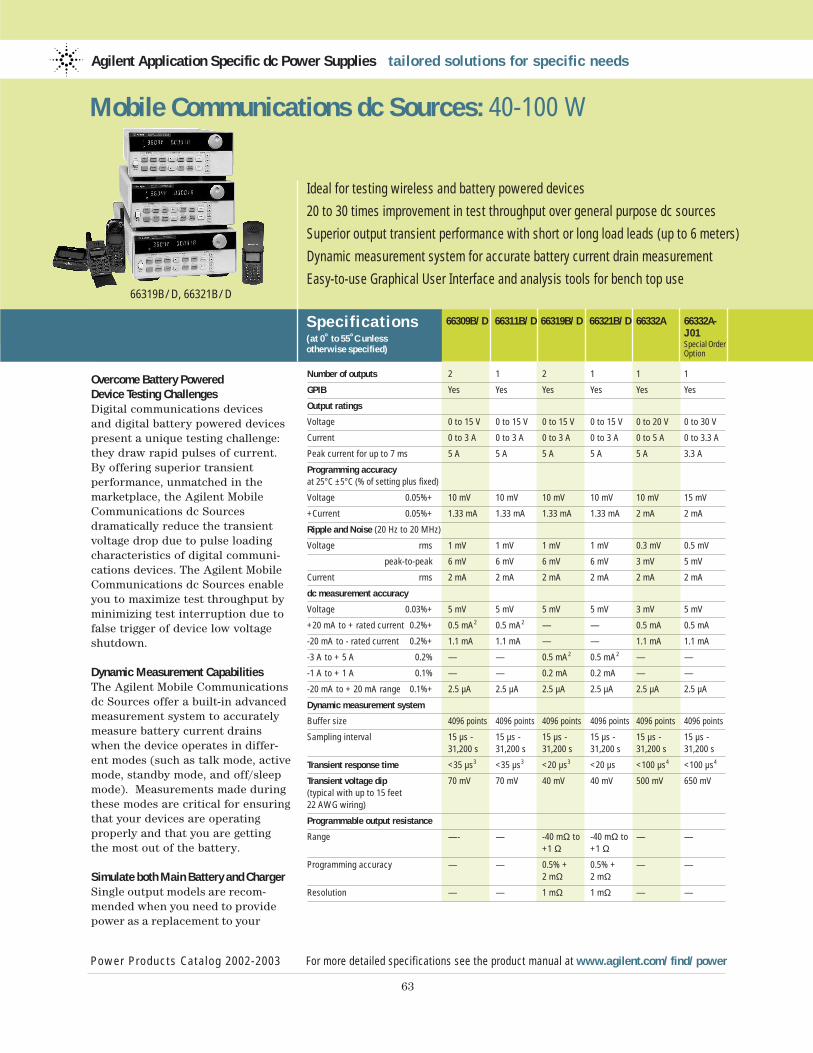
Overcome Battery Powered Device Testing ChallengesDigital communications devices and digital battery powered devicespresent a unique testing challenge:they draw rapid pulses of current.By offering superior transient performance, unmatched in themarketplace, the Agilent MobileCommunications dc Sources dramatically reduce the transientvoltage drop due to pulse loadingcharacteristics of digital communi-cations devices. The Agilent MobileCommunications dc Sources enableyou to maximize test throughput byminimizing test interruption due tofalse trigger of device low voltageshutdown.
Dynamic Measurement CapabilitiesThe Agilent Mobile Communicationsdc Sources offer a built-in advancedmeasurement system to accuratelymeasure battery current drainswhen the device operates in differ-ent modes (such as talk mode, activemode, standby mode, and off/sleepmode). Measurements made duringthese modes are critical for ensuringthat your devices are operatingproperly and that you are gettingthe most out of the battery.
Simulate both Main Battery and ChargerSingle output models are recom-mended when you need to providepower as a replacement to your
Agilent Application Specific dc Power Supplies tailored solutions for specific needs
Specif ications(at 0˚ to 55˚C unless otherwise specified)
66309B/D 66311B/D 66319B/D 66321B/D 66332A 66332A-J01Special OrderOption
Power Products Catalog 2002-2003 For more detailed specifications see the product manual at www.agilent.com/find/power
63
Ideal for testing wireless and battery powered devices
20 to 30 times improvement in test throughput over general purpose dc sources
Superior output transient performance with short or long load leads (up to 6 meters)
Dynamic measurement system for accurate battery current drain measurement
Easy-to-use Graphical User Interface and analysis tools for bench top use
Mobile Communications dc Sources: 40-100 W
Number of outputs 2 1 2 1 1 1
GPIB Yes Yes Yes Yes Yes Yes
Output ratings
Voltage 0 to 15 V 0 to 15 V 0 to 15 V 0 to 15 V 0 to 20 V 0 to 30 V
Current 0 to 3 A 0 to 3 A 0 to 3 A 0 to 3 A 0 to 5 A 0 to 3.3 A
Peak current for up to 7 ms 5 A 5 A 5 A 5 A 5 A 3.3 A
Programming accuracy at 25°C ±5°C (% of setting plus fixed)
Voltage 0.05%+ 10 mV 10 mV 10 mV 10 mV 10 mV 15 mV
+Current 0.05%+ 1.33 mA 1.33 mA 1.33 mA 1.33 mA 2 mA 2 mA
Ripple and Noise (20 Hz to 20 MHz)
Voltage rms 1 mV 1 mV 1 mV 1 mV 0.3 mV 0.5 mV
peak-to-peak 6 mV 6 mV 6 mV 6 mV 3 mV 5 mV
Current rms 2 mA 2 mA 2 mA 2 mA 2 mA 2 mA
dc measurement accuracy
Voltage 0.03%+ 5 mV 5 mV 5 mV 5 mV 3 mV 5 mV
+20 mA to + rated current 0.2%+ 0.5 mA2 0.5 mA2 — — 0.5 mA 0.5 mA
-20 mA to - rated current 0.2%+ 1.1 mA 1.1 mA — — 1.1 mA 1.1 mA
-3 A to + 5 A 0.2% — — 0.5 mA2 0.5 mA2 — —
-1 A to + 1 A 0.1% — — 0.2 mA 0.2 mA — —
-20 mA to + 20 mA range 0.1%+ 2.5 µA 2.5 µA 2.5 µA 2.5 µA 2.5 µA 2.5 µA
Dynamic measurement system
Buffer size 4096 points 4096 points 4096 points 4096 points 4096 points 4096 points
Sampling interval 15 µs - 15 µs - 15 µs - 15 µs - 15 µs - 15 µs - 31,200 s 31,200 s 31,200 s 31,200 s 31,200 s 31,200 s
Transient response time <35 µs3 <35 µs3 <20 µs3 <20 µs <100 µs4 <100 µs4
Transient voltage dip 70 mV 70 mV 40 mV 40 mV 500 mV 650 mV(typical with up to 15 feet 22 AWG wiring)
Programmable output resistance
Range —- — -40 mΩ to -40 mΩ to — —+1 Ω +1 Ω
Programming accuracy — — 0.5% + 0.5% + — —2 mΩ 2 mΩ
Resolution — — 1 mΩ 1 mΩ — —
66319B/D, 66321B/D
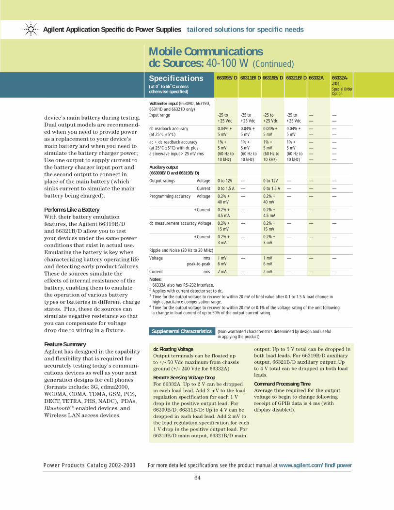
64
device’s main battery during testing.Dual output models are recommend-ed when you need to provide poweras a replacement to your device’smain battery and when you need tosimulate the battery charger power;Use one output to supply current tothe battery charger input port andthe second output to connect inplace of the main battery (whichsinks current to simulate the mainbattery being charged).
Performs Like a BatteryWith their battery emulation features, the Agilent 66319B/D and 66321B/D allow you to test your devices under the same power conditions that exist in actual use.Emulating the battery is key whencharacterizing battery operating lifeand detecting early product failures.These dc sources simulate theeffects of internal resistance of thebattery, enabling them to emulatethe operation of various batterytypes or batteries in different chargestates. Plus, these dc sources cansimulate negative resistance so thatyou can compensate for voltage drop due to wiring in a fixture.
Feature SummaryAgilent has designed in the capabilityand flexibility that is required foraccurately testing today’s communi-cations devices as well as your nextgeneration designs for cell phones(formats include: 3G, cdma2000,WCDMA, CDMA, TDMA, GSM, PCS,DECT, TETRA, PHS, NADC), PDAs,BluetoothTM enabled devices, andWireless LAN access devices.
Mobile Communications dc Sources: 40-100 W (Continued)
Specif ications(at 0˚ to 55˚C unless otherwise specified)
Power Products Catalog 2002-2003 For more detailed specifications see the product manual at www.agilent.com/find/power
Agilent Application Specific dc Power Supplies tailored solutions for specific needs
66309B/D 66311B/D 66319B/D 66321B/D 66332A 66332A-J01Special OrderOption
Voltmeter input (66309D, 66319D, 66311D and 66321D only)Input range -25 to -25 to -25 to -25 to — —
+25 Vdc +25 Vdc +25 Vdc +25 Vdc — —
dc readback accuracy 0.04% + 0.04% + 0.04% + 0.04% + — —(at 25°C ±5°C) 5 mV 5 mV 5 mV 5 mV — —
ac + dc readback accuracy 1% + 1% + 1% + 1% + — —(at 25°C ±5°C) with dc plus 5 mV 5 mV 5 mV 5 mV — — a sinewave input > 25 mV rms (60 Hz to (60 Hz to (60 Hz to (60 Hz to — —
10 kHz) 10 kHz) 10 kHz) 10 kHz) — —
Auxilary output (66309B/D and 66319B/D)
Output ratings Voltage 0 to 12V — 0 to 12V — — —
Current 0 to 1.5 A — 0 to 1.5 A — — —
Programming accuracy Voltage 0.2% + — 0.2% + — — —40 mV 40 mV
+Current 0.2% + — 0.2% + — — —4.5 mA 4.5 mA
dc measurement accuracy Voltage 0.2% + — 0.2% + — — —15 mV 15 mV
+Current 0.2% + — 0.2% + — — —3 mA 3 mA
Ripple and Noise (20 Hz to 20 MHz)
Voltage rms 1 mV — 1 mV — — —peak-to-peak 6 mV 6 mV
Current rms 2 mA — 2 mA — — —
Notes:1 66332A also has RS-232 interface.2 Applies with current detector set to dc.3 Time for the output voltage to recover to within 20 mV of final value after 0.1 to 1.5 A load change in
high capacitance compensation range.4 Time for the output voltage to recover to within 20 mV or 0.1% of the voltage rating of the unit following
a change in load current of up to 50% of the output current rating.
Supplemental Characteristics (Non-warranted characteristics determined by design and useful in applying the product)
dc Floating VoltageOutput terminals can be floated up to +/- 50 Vdc maximum from chassisground (+/- 240 Vdc for 66332A)
Remote Sensing Voltage DropFor 66332A: Up to 2 V can be dropped in each load lead. Add 2 mV to the loadregulation specification for each 1 Vdrop in the positive output lead. For66309B/D, 66311B/D: Up to 4 V can bedropped in each load lead. Add 2 mV tothe load regulation specification for each1 V drop in the positive output lead. For66319B/D main output, 66321B/D main
output: Up to 3 V total can be dropped inboth load leads. For 66319B/D auxiliaryoutput, 66321B/D auxiliary output: Up to 4 V total can be dropped in both loadleads.
Command Processing TimeAverage time required for the outputvoltage to begin to change followingreceipt of GPIB data is 4 ms (with display disabled).
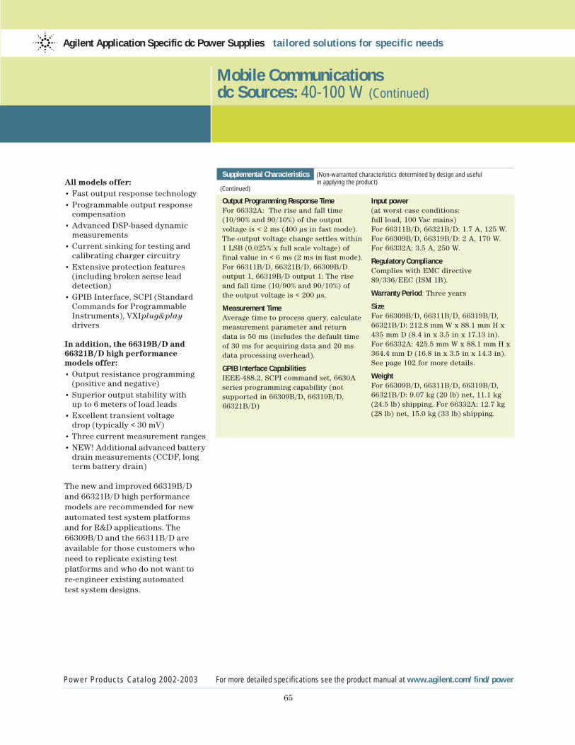
65
All models offer:• Fast output response technology• Programmable output response
compensation• Advanced DSP-based dynamic
measurements• Current sinking for testing and
calibrating charger circuitry• Extensive protection features
(including broken sense lead detection)
• GPIB Interface, SCPI (Standard Commands for Programmable Instruments), VXIplug&playdrivers
In addition, the 66319B/D and66321B/D high performance models offer:• Output resistance programming
(positive and negative)• Superior output stability with
up to 6 meters of load leads• Excellent transient voltage
drop (typically < 30 mV)• Three current measurement ranges• NEW! Additional advanced battery
drain measurements (CCDF, long term battery drain)
The new and improved 66319B/Dand 66321B/D high performancemodels are recommended for newautomated test system platformsand for R&D applications. The66309B/D and the 66311B/D areavailable for those customers whoneed to replicate existing test platforms and who do not want tore-engineer existing automated test system designs.
Mobile Communications dc Sources: 40-100 W (Continued)
Power Products Catalog 2002-2003 For more detailed specifications see the product manual at www.agilent.com/find/power
Agilent Application Specific dc Power Supplies tailored solutions for specific needs
Supplemental Characteristics (Non-warranted characteristics determined by design and useful in applying the product)
(Continued)
Output Programming Response TimeFor 66332A: The rise and fall time(10/90% and 90/10%) of the output voltage is < 2 ms (400 µs in fast mode).The output voltage change settles within1 LSB (0.025% x full scale voltage) offinal value in < 6 ms (2 ms in fast mode).For 66311B/D, 66321B/D, 66309B/D output 1, 66319B/D output 1: The riseand fall time (10/90% and 90/10%) of the output voltage is < 200 µs.
Measurement TimeAverage time to process query, calculatemeasurement parameter and return data is 50 ms (includes the default timeof 30 ms for acquiring data and 20 msdata processing overhead).
GPIB Interface CapabilitiesIEEE-488.2, SCPI command set, 6630Aseries programming capability (not supported in 66309B/D, 66319B/D,66321B/D)
Input power(at worst case conditions: full load, 100 Vac mains)For 66311B/D, 66321B/D: 1.7 A, 125 W.For 66309B/D, 66319B/D: 2 A, 170 W.For 66332A: 3.5 A, 250 W.
Regulatory ComplianceComplies with EMC directive89/336/EEC (ISM 1B).
Warranty Period Three years
SizeFor 66309B/D, 66311B/D, 66319B/D,66321B/D: 212.8 mm W x 88.1 mm H x435 mm D (8.4 in x 3.5 in x 17.13 in).For 66332A: 425.5 mm W x 88.1 mm H x364.4 mm D (16.8 in x 3.5 in x 14.3 in).See page 102 for more details.
WeightFor 66309B/D, 66311B/D, 66319B/D,66321B/D: 9.07 kg (20 lb) net, 11.1 kg(24.5 lb) shipping. For 66332A: 12.7 kg(28 lb) net, 15.0 kg (33 lb) shipping.
66
Mobile Communications dc Sources: 40-100 W (Continued)
Power Products Catalog 2002-2003 For more detailed specifications see the product manual at www.agilent.com/find/power
Agilent Application Specific dc Power Supplies tailored solutions for specific needs
Accessories
p/n 1494-0060 Rack Slide Kit (66332A only)
E3663AC Support rails for Agilent rack cabinets
14565A Device Characterization Software with Battery Drain Analysis
Note: Battery Drain Analysis means Data Logging and CCDF measurements.These capabilities require models66319B, 66319D, 66321B or 66321D withversion A.03.00 firmware or higher and14565A software version 3.01 or higher.
Ordering Information
Opt 100 87 to 106 Vac, 47 to 63 HzOpt 120 104 to 127 Vac, 47 to 63 HzOpt 220 191 to 233 Vac, 47 to 63 HzOpt 230 207 to 253 Vac, 47 to 63 HzOpt 004 Make “Hi Compensation Mode”as default settingOpt 020 Front-panel Binding Posts (66332A only)Opt UJ0 No front panel binding posts(66332A only)Opt 053 Add 14565A Device Character-ization Software with Battery Drain Analysis (66319B/D, 66321B/D)Opt 521 Solid State Relays (66309B/D, 66319B/D)Opt AYK No Solid State Relays (66309B/D,66319B/D)Opt 760 Isolation and Reversal Relays (66332A only)Opt 8ZJ Delete feetOpt 8ZL Include feet
* Opt 1CM Rack-mount kit 66309B/D,66311B/D, 66319B/D, 66321B/D: p/n 5062-3975; 66332A: p/n 5062-3974
* Opt 1CP Rack-mount Kit with Handles,p/n 5062-3975 (66332A only)
* Opt AXS Rack-mount Kit for side-by-sidemounting, (N/A for 66332A) Locking Kit p/n 5061-9694; Flange Kit p/n 5062-3974Opt 0B0 Delete standard documentation packageOpt 0L1 Include standard documentation packageOpt 0L2 Include extra standard documentation packageOpt 0B3 Include service manual
*Support rails required
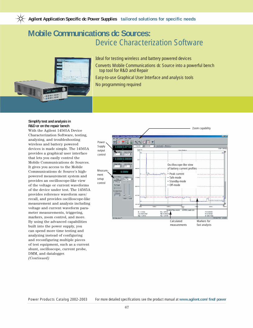
Simplify test and analysis in R&D or on the repair benchWith the Agilent 14565A DeviceCharacterization Software, testing,analyzing, and troubleshooting wireless and battery powereddevices is made simple. The 14565Aprovides a graphical user interfacethat lets you easily control theMobile Communications dc Sources.It gives you access to the MobileCommunications dc Source’s high-powered measurement system andprovides an oscilloscope-like view of the voltage or current waveformsof the device under test. The 14565Aprovides reference waveform save/recall, and provides oscilloscope-likemeasurement and analysis includingvoltage and current waveform para-meter measurements, triggering,markers, zoom control, and more.By using the advanced capabilitiesbuilt into the power supply, you can spend more time testing andanalyzing instead of configuring and reconfiguring multiple pieces of test equipment, such as a currentshunt, oscilloscope, current probe,DMM, and datalogger.(Continued)
Agilent Application Specific dc Power Supplies tailored solutions for specific needs
Power Products Catalog 2002-2003 For more detailed specifications see the product manual at www.agilent.com/find/power
67
Ideal for testing wireless and battery powered devices
Converts Mobile Communications dc Source into a powerful benchtop tool for R&D and Repair
Easy-to-use Graphical User Interface and analysis tools
No programming required
Mobile Communications dc Sources: Device Characterization Software
Zoom capability
Power
Supply
output
control
Measure-
ment
setup
control
Oscilloscope-like view of battery current profiles
• Peak current• Talk-mode• Standby-mode• Off-mode
Calculatedmeasurements
Markers for fast analysts
68
When coupled with the 66319B/Dor the 66321B/D, the 14565A alsoprovides Battery Drain Analysiscapabilities. More than just measur-ing battery run time, Battery DrainAnalysis allows you to characterizecurrent out of the battery andmake tradeoffs in design thatimpact the current drain and bat-tery life. This new version of the14565A includes the measurementand data reduction tools needed toanalyze and visualize the currentbeing drained from your battery.By providing CCDF measurementsand long-term battery drain datalogging, the 14565A and 66319/21provide a complete solution foranalyzing complex current wave-forms so that you can optimizeyour device designs to achieve maximum battery run time.
Mobile Communications dc Sources: Device Characterization Software (Continued)
Power Products Catalog 2002-2003 For more detailed specifications see the product manual at www.agilent.com/find/power
Agilent Application Specific dc Power Supplies tailored solutions for specific needs
Key features
For R&D• Fast and easy test setup• Digitize current waveforms• Accurately log battery current
drain measurements from 10 seconds to 1000 hours at 64,000 measurements per second
• Test designs simulating differentbattery states (charged, aged, elevated temperatures, etc.) and chemistries (Ni-Cad to Lithium Polymer)
• Zoom capability for analyzing waveform anomalies
• Adjust markers for fast measure-ments on digitized waveforms
• Easily document your test results• Record test data to files for
archive or analysis by other software packages
For Repair• Compact design with multiple
instrument functionality• Fast and easy test setup• Graphical user software,
no programming required• Dual dc outputs for replacing
the main battery and the power adapter/charger power source
• Electronic load for testing the battery charger circuitry
• Programmable soft limits to protect against incorrect voltage settings
Ordering Information
14565A Device Characterization Software with Battery Drain Analysis
Note: Battery Drain Analysis means Data Logging and CCDF measurements.These capabilities require models66319B, 66319D, 66321B or 66321D withversion A.03.00 firmware or higher and14565A software version 3.01 or higher.
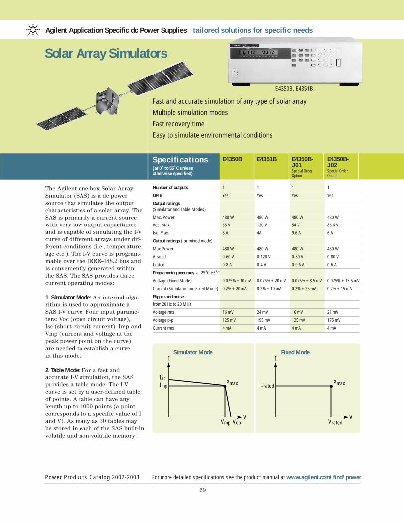
The Agilent one-box Solar ArraySimulator (SAS) is a dc powersource that simulates the outputcharacteristics of a solar array. TheSAS is primarily a current sourcewith very low output capacitanceand is capable of simulating the I-Vcurve of different arrays under dif-ferent conditions (i.e., temperature,age etc.). The I-V curve is program-mable over the IEEE-488.2 bus andis conveniently generated within the SAS. The SAS provides threecurrent operating modes:
1. Simulator Mode: An internal algo-rithm is used to approximate a SAS I-V curve. Four input parame-ters: Voc (open circuit voltage), Isc (short circuit current), Imp andVmp (current and voltage at thepeak power point on the curve) are needed to establish a curve in this mode.
2. Table Mode: For a fast and accurate I-V simulation, the SASprovides a table mode. The I-Vcurve is set by a user-defined tableof points. A table can have anylength up to 4000 points (a pointcorresponds to a specific value of Iand V). As many as 30 tables maybe stored in each of the SAS built-involatile and non-volatile memory.
Agilent Application Specific dc Power Supplies tailored solutions for specific needs
Power Products Catalog 2002-2003 For more detailed specifications see the product manual at www.agilent.com/find/power
69
Fast and accurate simulation of any type of solar array
Multiple simulation modes
Fast recovery time
Easy to simulate environmental conditions
Solar Array Simulators
Specif ications(at 0˚ to 55˚C unless otherwise specified)
E4350B E4351B E4350B- E4350B-J01 J02Special Order Special OrderOption Option
Number of outputs 1 1 1 1
GPIB Yes Yes Yes Yes
Output ratings (Simulator and Table Modes)
Max. Power 480 W 480 W 480 W 480 W
Voc. Max. 65 V 130 V 54 V 86.6 V
Isc. Max. 8 A 4A 9.6 A 6 A
Output ratings (for mixed mode)
Max Power 480 W 480 W 480 W 480 W
V rated 0-60 V 0-120 V 0-50 V 0-80 V
I rated 0-8 A 0-4 A 0-9.6 A 0-6 A
Programming accuracy at 25˚C ±5˚C
Voltage (Fixed Mode) 0.075% + 10 mV 0.075% + 20 mV 0.075% + 8.5 mV 0.075% + 13.5 mV
Current (Simulator and Fixed Mode) 0.2% + 20 mA 0.2% + 10 mA 0.2% + 25 mA 0.2% + 15 mA
Ripple and noise
from 20 Hz to 20 MHz
Voltage rms 16 mV 24 mV 16 mV 21 mV
Voltage p-p 125 mV 195 mV 125 mV 175 mV
Current rms 4 mA 4 mA 4 mA 4 mA
IacImp
Pmax
I
VVmp Voo
I ratedPmax
I
VVrated
E4350B, E4351B
Simulator Mode Fixed Mode
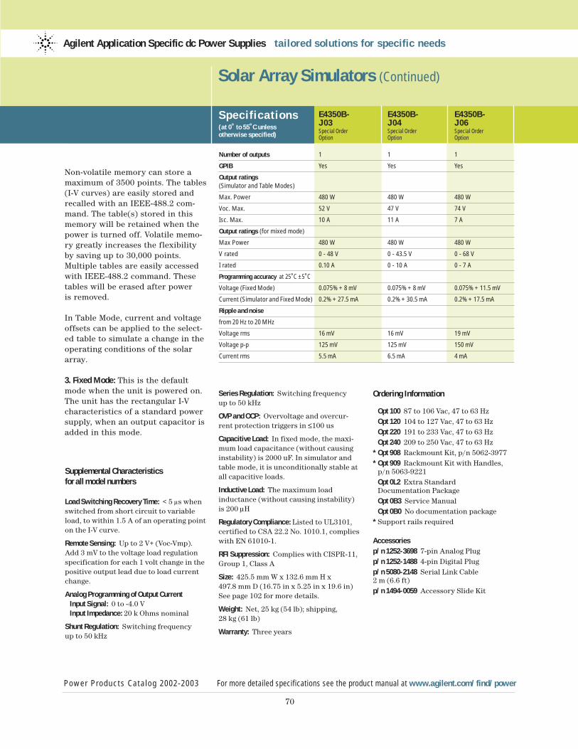
70
Supplemental Characteristicsfor all model numbers
Load Switching Recovery Time: < 5 µs whenswitched from short circuit to variableload, to within 1.5 A of an operating pointon the I-V curve.
Remote Sensing: Up to 2 V+ (Voc-Vmp). Add 3 mV to the voltage load regulationspecification for each 1 volt change in thepositive output lead due to load currentchange.
Analog Programming of Output CurrentInput Signal: 0 to -4.0 VInput Impedance: 20 k Ohms nominal
Shunt Regulation: Switching frequency up to 50 kHz
Solar Array Simulators (Continued)
Power Products Catalog 2002-2003 For more detailed specifications see the product manual at www.agilent.com/find/power
Agilent Application Specific dc Power Supplies tailored solutions for specific needs
Non-volatile memory can store amaximum of 3500 points. The tables(I-V curves) are easily stored andrecalled with an IEEE-488.2 com-mand. The table(s) stored in thismemory will be retained when thepower is turned off. Volatile memo-ry greatly increases the flexibilityby saving up to 30,000 points.Multiple tables are easily accessedwith IEEE-488.2 command. Thesetables will be erased after poweris removed.
In Table Mode, current and voltageoffsets can be applied to the select-ed table to simulate a change in theoperating conditions of the solararray.
3. Fixed Mode: This is the defaultmode when the unit is powered on.The unit has the rectangular I-Vcharacteristics of a standard powersupply, when an output capacitor isadded in this mode.
Specif ications(at 0˚ to 55˚C unless otherwise specified)
E4350B- E4350B- E4350B-J03 J04 J06Special Order Special Order Special OrderOption Option Option
Number of outputs 1 1 1
GPIB Yes Yes Yes
Output ratings (Simulator and Table Modes)
Max. Power 480 W 480 W 480 W
Voc. Max. 52 V 47 V 74 V
Isc. Max. 10 A 11 A 7 A
Output ratings (for mixed mode)
Max Power 480 W 480 W 480 W
V rated 0 - 48 V 0 - 43.5 V 0 - 68 V
I rated 0.10 A 0 - 10 A 0 - 7 A
Programming accuracy at 25˚C ±5˚C
Voltage (Fixed Mode) 0.075% + 8 mV 0.075% + 8 mV 0.075% + 11.5 mV
Current (Simulator and Fixed Mode) 0.2% + 27.5 mA 0.2% + 30.5 mA 0.2% + 17.5 mA
Ripple and noise
from 20 Hz to 20 MHz
Voltage rms 16 mV 16 mV 19 mV
Voltage p-p 125 mV 125 mV 150 mV
Current rms 5.5 mA 6.5 mA 4 mA
Series Regulation: Switching frequency up to 50 kHz
OVP and OCP: Overvoltage and overcur-rent protection triggers in ≤100 us
Capacitive Load: In fixed mode, the maxi-mum load capacitance (without causinginstability) is 2000 uF. In simulator andtable mode, it is unconditionally stable atall capacitive loads.
Inductive Load: The maximum load inductance (without causing instability)is 200 µH
Regulatory Compliance: Listed to UL3101,certified to CSA 22.2 No. 1010.1, complieswith EN 61010-1.
RFI Suppression: Complies with CISPR-11,Group 1, Class A
Size: 425.5 mm W x 132.6 mm H x 497.8 mm D (16.75 in x 5.25 in x 19.6 in) See page 102 for more details.
Weight: Net, 25 kg (54 lb); shipping, 28 kg (61 lb)
Warranty: Three years
Ordering Information
Opt 100 87 to 106 Vac, 47 to 63 HzOpt 120 104 to 127 Vac, 47 to 63 HzOpt 220 191 to 233 Vac, 47 to 63 HzOpt 240 209 to 250 Vac, 47 to 63 Hz
* Opt 908 Rackmount Kit, p/n 5062-3977* Opt 909 Rackmount Kit with Handles,
p/n 5063-9221Opt 0L2 Extra Standard Documentation PackageOpt 0B3 Service ManualOpt 0B0 No documentation package
* Support rails required
Accessoriesp/n 1252-3698 7-pin Analog Plugp/n 1252-1488 4-pin Digital Plugp/n 5080-2148 Serial Link Cable2 m (6.6 ft)p/n 1494-0059 Accessory Slide Kit
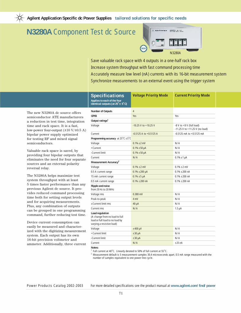
The new N3280A dc source offerssemiconductor ATE manufacturersa reduction in test time, integrationtime and rack space. It is a fast, low-power four-output (±10 V/±0.5 A)bipolar power supply optimized for testing RF and mixed signalsemiconductors.
Valuable rack space is saved, by providing four bipolar outputs thateliminates the need for four separatesources and an external polarityreversal relay.
The N3280A helps maximize testsystem throughput with at least 5 times faster performance than anyprevious Agilent dc source. It pro-vides reduced command processingtime both for setting output levelsand for acquiring measurements.Plus, any combination of outputscan be grouped in one programmingcommand, further reducing test time.
Device current consumption caneasily be measured and character-ized with the digitizing measurementsystem. Each output has its own 16-bit precision voltmeter andammeter. Additionally, three current
Agilent Application Specific dc Power Supplies tailored solutions for specific needs
Specif icationsApplies to each of the four identical outputs (at 25˚± 5˚C)
Voltage Priority Mode Current Priority Mode
Power Products Catalog 2002-2003 For more detailed specifications see the product manual at www.agilent.com/find/power
71
Save valuable rack space with 4 outputs in a one-half rack box
Increase system throughput with fast command processing time
Accurately measure low level (nA) currents with its 16-bit measurement system
Synchronize measurements to an external event using the trigger system
N3280A
N3280A Component Test dc Source
Number of Outputs 4
GPIB Yes Yes
Output ratings1
Voltage -10.25 V to +10.25 V -8 V to +8 V (full load) -11.25 V to +11.25 V (no load)
Current -0.5125 A to +0.5125 A -0.5125 mA to +0.5125 mA
Programming accuracy at 25˚C ±5˚C
Voltage 0.1% ±2 mV N/A
+Current 0.1% ±50 µA N/A
-Current limit 0.1% ±50 µA N/A
Current N/A 0.1% ±1 µA
Measurement Accuracy2
Voltage 0.1% ±2 mV 0.1% ±2 mV
0.5 A current range 0.1% ±200 µA 0.1% ±200 nA
15 mA current range 0.1% ±5 µA 0.1% ±200 nA
0.5 mA current range 0.1% ±200 nA 0.1% ±200 nA
Ripple and noisefrom 20 Hz to 20 MHz
Voltage rms 0.380 mV N/A
Peak-to-peak 4 mV N/A
±Current limit rms 40 µA N/A
Current rms N/A 1.5 µA
Load regulation(A change from no load to full load or full load to no load by varying a resistive load)
Voltage ±400 µV N/A
+Current limit ±30 µA N/A
-Current limit ±30 µA N/A
Current N/A ±25 nA
Notes:1 Full current at 40˚C. Linearly derated to 50% of full current at 55˚C.2 Measurement default is 5 measurement samples 30.4 microseconds apart. 0.5 mA range measured with the
number of samples equivalent to one power line cycle.
3
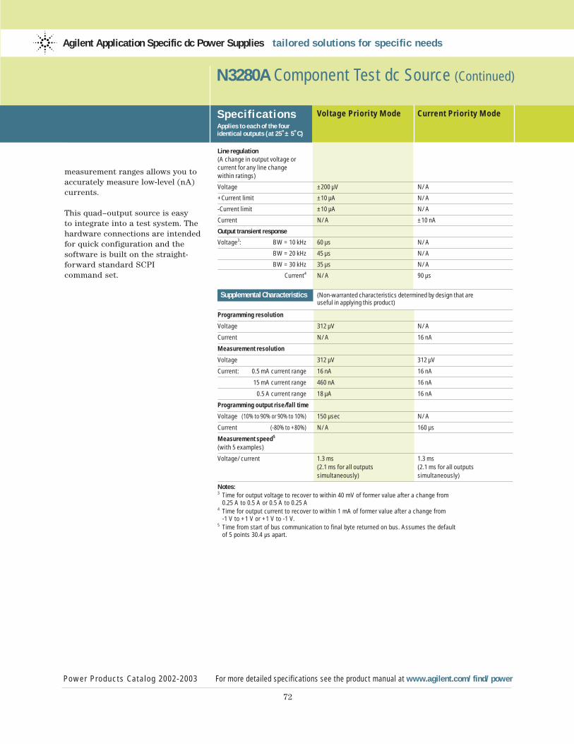
72
measurement ranges allows you toaccurately measure low-level (nA)currents.
This quad–output source is easy to integrate into a test system. Thehardware connections are intendedfor quick configuration and the software is built on the straight-forward standard SCPI command set.
N3280A Component Test dc Source (Continued)
Power Products Catalog 2002-2003 For more detailed specifications see the product manual at www.agilent.com/find/power
Agilent Application Specific dc Power Supplies tailored solutions for specific needs
Specif icationsApplies to each of the four identical outputs (at 25˚± 5˚C)
Voltage Priority Mode Current Priority Mode
Line regulation (A change in output voltage or current for any line change within ratings)
Voltage ±200 µV N/A
+Current limit ±10 µA N/A
-Current limit ±10 µA N/A
Current N/A ±10 nA
Output transient response
Voltage3: BW = 10 kHz 60 µs N/A
BW = 20 kHz 45 µs N/A
BW = 30 kHz 35 µs N/A
Current4 N/A 90 µs
Supplemental Characteristics (Non-warranted characteristics determined by design that are useful in applying this product)
Programming resolution
Voltage 312 µV N/A
Current N/A 16 nA
Measurement resolution
Voltage 312 µV 312 µV
Current: 0.5 mA current range 16 nA 16 nA
15 mA current range 460 nA 16 nA
0.5 A current range 18 µA 16 nA
Programming output rise/fall time
Voltage (10% to 90% or 90% to 10%) 150 µsec N/A
Current (-80% to +80%) N/A 160 µs
Measurement speed5
(with 5 examples)
Voltage/current 1.3 ms 1.3 ms(2.1 ms for all outputs (2.1 ms for all outputssimultaneously) simultaneously)
Notes:3 Time for output voltage to recover to within 40 mV of former value after a change from
0.25 A to 0.5 A or 0.5 A to 0.25 A4 Time for output current to recover to within 1 mA of former value after a change from
-1 V to +1 V or +1 V to -1 V.5 Time from start of bus communication to final byte returned on bus. Assumes the default
of 5 points 30.4 µs apart.
73
N3280A Component Test dc Source (Continued)
Power Products Catalog 2002-2003 For more detailed specifications see the product manual at www.agilent.com/find/power
Agilent Application Specific dc Power Supplies tailored solutions for specific needs
Supplemental Characteristicsfor all model numbers
dc Floating Voltage: Output terminals canbe floated up to ±50 Vdc maximum fromchassis ground and ±100 Vdc from outputto output.
Remote Sensing: Up to 1/2 the maximumoutput voltage may be dropped acrosseach load lead. Add 1/2 mV to the loadregulation for each 1 V change in the HIoutput lead.
Command Processing Time: The time to set an output parameter is 0.6 ms for a single output (0.7 ms for all outputs simultaneously). Time to query a setting is 1.0 ms (1.5 ms for all outputssimultaneously)
Dynamic Measurement SystemBuffer Size = 4096 pointsSampling rate increments = 30.4 µs
Input Power (full load):
Voltage 100 Vac 120 Vac 220 Vac 230 Vac
Current 1.85 A 1.55 A 0.90 A 0.80 A(max)
Power 140 W 140 W 140 W 140 W(max)
Regulatory Compliance: Complies withEMC directive 89/336/EEC (ISM group 1 Class A)
Warranty Period: 18 months
Size: 212.7 mm W x 88.9 mm H x 497.8 mm D (8.4 in x 3.5 in x 19.6 in)See page 105 for more details.
Weight: 10 kg (22 lbs) net; 11.8 kg (26 lbs)shipping
Ordering Information
Opt 100 87 to 106 Vac, 47 to 63 HzOpt 120 104 to 127 Vac, 47 to 63 HzOpt 220 191 to 233 Vac, 47 to 63 HzOpt 230 207 to 253 Vac, 47 to 63 HzOpt 0B0 Delete manual setOpt 0L1 Standard documentation packageOpt 0L2 Extra standard documentation packageOpt 8ZL Add feet – for bench use, p/n 5041-9167Opt 1CM Rackmount kit, p/n 5063-9240Opt AXS Rackmount kit for side-by-side mounting, Lock-link kit p/n 5061-9694; Flange Kit p/n 5063-9212; Tie Bracket Kit p/n 5965-6947
Accessoriesp/n N3280A-10001 Virtual Front Panel Software
Key LiteratureAgilent N3280A Component Test dc Source Datasheet p/n 5988-7080EN
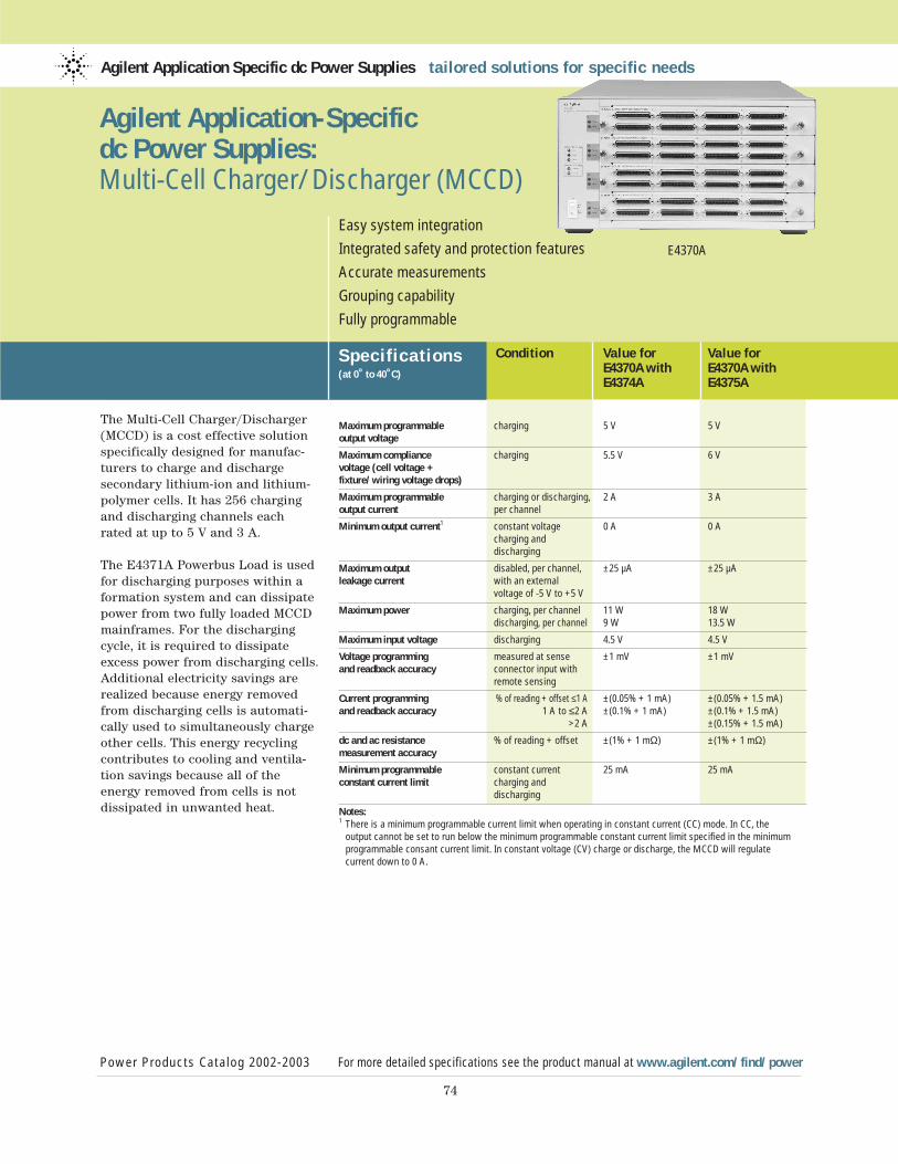
The Multi-Cell Charger/Discharger(MCCD) is a cost effective solutionspecifically designed for manufac-turers to charge and discharge secondary lithium-ion and lithium-polymer cells. It has 256 chargingand discharging channels each rated at up to 5 V and 3 A.
The E4371A Powerbus Load is usedfor discharging purposes within aformation system and can dissipatepower from two fully loaded MCCDmainframes. For the dischargingcycle, it is required to dissipateexcess power from discharging cells.Additional electricity savings arerealized because energy removedfrom discharging cells is automati-cally used to simultaneously chargeother cells. This energy recyclingcontributes to cooling and ventila-tion savings because all of the energy removed from cells is notdissipated in unwanted heat.
Agilent Application Specific dc Power Supplies tailored solutions for specific needs
Specif ications(at 0˚ to 40˚C)
Power Products Catalog 2002-2003 For more detailed specifications see the product manual at www.agilent.com/find/power
74
Easy system integration
Integrated safety and protection features
Accurate measurements
Grouping capability
Fully programmable
E4370A
Agilent Application-Specificdc Power Supplies: Multi-Cell Charger/Discharger (MCCD)
Condition Value for Value forE4370A with E4370A with E4374A E4375A
Maximum programmable charging 5 V 5 Voutput voltage
Maximum compliance charging 5.5 V 6 Vvoltage (cell voltage + fixture/wiring voltage drops)
Maximum programmable charging or discharging, 2 A 3 Aoutput current per channel
Minimum output current1 constant voltage 0 A 0 Acharging and discharging
Maximum output disabled, per channel, ±25 µA ±25 µAleakage current with an external
voltage of -5 V to +5 V
Maximum power charging, per channel 11 W 18 Wdischarging, per channel 9 W 13.5 W
Maximum input voltage discharging 4.5 V 4.5 V
Voltage programming measured at sense ±1 mV ±1 mVand readback accuracy connector input with
remote sensing
Current programming % of reading + offset ≤1 A ±(0.05% + 1 mA) ±(0.05% + 1.5 mA)and readback accuracy 1 A to ≤2 A ±(0.1% + 1 mA) ±(0.1% + 1.5 mA)
>2 A ±(0.15% + 1.5 mA)
dc and ac resistance % of reading + offset ±(1% + 1 mΩ) ±(1% + 1 mΩ)measurement accuracy
Minimum programmable constant current 25 mA 25 mAconstant current limit charging and
discharging
Notes:1 There is a minimum programmable current limit when operating in constant current (CC) mode. In CC, the
output cannot be set to run below the minimum programmable constant current limit specified in the minimum programmable consant current limit. In constant voltage (CV) charge or discharge, the MCCD will regulate current down to 0 A.
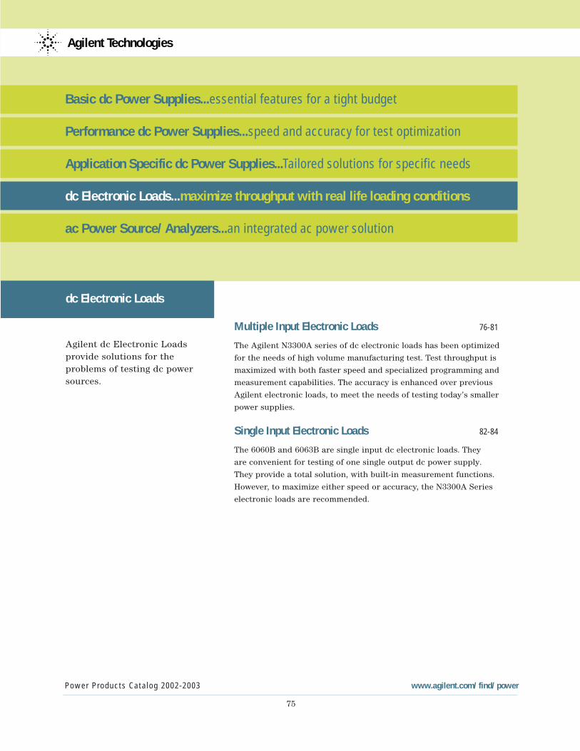
Power Products Catalog 2002-2003 www.agilent.com/find/power
75
Agilent Technologies
Basic dc Power Supplies...essential features for a tight budget
Performance dc Power Supplies...speed and accuracy for test optimization
Application Specific dc Power Supplies...Tailored solutions for specific needs
dc Electronic Loads...maximize throughput with real life loading conditions
ac Power Source/Analyzers...an integrated ac power solution
dc Electronic Loads
Agilent dc Electronic Loadsprovide solutions for the problems of testing dc powersources.
Multiple Input Electronic Loads 76-81
The Agilent N3300A series of dc electronic loads has been optimized
for the needs of high volume manufacturing test. Test throughput is
maximized with both faster speed and specialized programming and
measurement capabilities. The accuracy is enhanced over previous
Agilent electronic loads, to meet the needs of testing today’s smaller
power supplies.
Single Input Electronic Loads 82-84
The 6060B and 6063B are single input dc electronic loads. They
are convenient for testing of one single output dc power supply.
They provide a total solution, with built-in measurement functions.
However, to maximize either speed or accuracy, the N3300A Series
electronic loads are recommended.
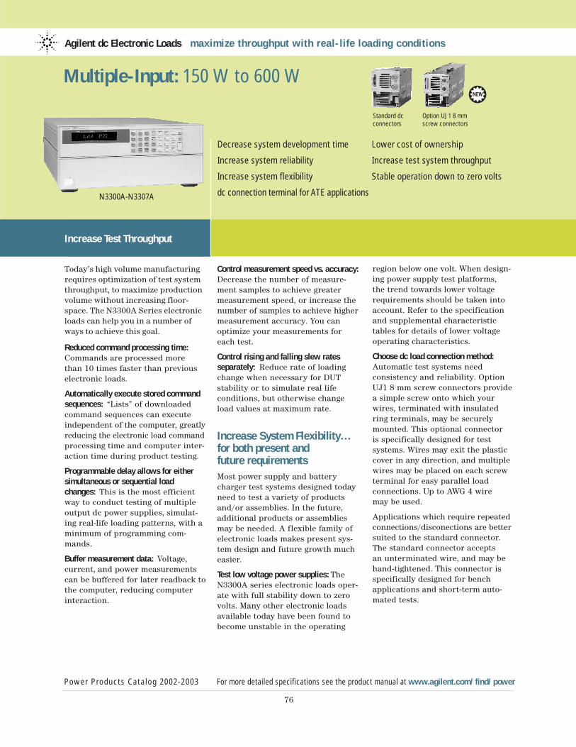
Agilent dc Electronic Loads maximize throughput with real-life loading conditions
Power Products Catalog 2002-2003 For more detailed specifications see the product manual at www.agilent.com/find/power
76
Decrease system development time Lower cost of ownership
Increase system reliability Increase test system throughput
Increase system flexibility Stable operation down to zero volts
dc connection terminal for ATE applicationsN3300A-N3307A
Multiple-Input: 150 W to 600 W
Control measurement speed vs. accuracy:Decrease the number of measure-ment samples to achieve greatermeasurement speed, or increase thenumber of samples to achieve highermeasurement accuracy. You canoptimize your measurements foreach test.
Control rising and falling slew rates separately: Reduce rate of loadingchange when necessary for DUT stability or to simulate real life conditions, but otherwise changeload values at maximum rate.
Increase System Flexibility…for both present and future requirements Most power supply and batterycharger test systems designed todayneed to test a variety of productsand/or assemblies. In the future,additional products or assembliesmay be needed. A flexible family ofelectronic loads makes present sys-tem design and future growth mucheasier.
Test low voltage power supplies: TheN3300A series electronic loads oper-ate with full stability down to zerovolts. Many other electronic loadsavailable today have been found tobecome unstable in the operating
region below one volt. When design-ing power supply test platforms, the trend towards lower voltagerequirements should be taken intoaccount. Refer to the specificationand supplemental characteristictables for details of lower voltageoperating characteristics.
Choose dc load connection method:Automatic test systems need consistency and reliability. OptionUJ1 8 mm screw connectors providea simple screw onto which yourwires, terminated with insulatedring terminals, may be securelymounted. This optional connector is specifically designed for test systems. Wires may exit the plasticcover in any direction, and multiplewires may be placed on each screwterminal for easy parallel load connections. Up to AWG 4 wire may be used.
Applications which require repeatedconnections/disconections are bettersuited to the standard connector.The standard connector accepts an unterminated wire, and may behand-tightened. This connector isspecifically designed for benchapplications and short-term auto-mated tests.
Increase Test Throughput
Today’s high volume manufacturingrequires optimization of test systemthroughput, to maximize productionvolume without increasing floor-space. The N3300A Series electronicloads can help you in a number ofways to achieve this goal.
Reduced command processing time:Commands are processed more than 10 times faster than previouselectronic loads.
Automatically execute stored commandsequences: “Lists” of downloadedcommand sequences can executeindependent of the computer, greatlyreducing the electronic load commandprocessing time and computer inter-action time during product testing.
Programmable delay allows for eithersimultaneous or sequential loadchanges: This is the most efficientway to conduct testing of multipleoutput dc power supplies, simulat-ing real-life loading patterns, with aminimum of programming com-mands.
Buffer measurement data: Voltage, current, and power measurementscan be buffered for later readback tothe computer, reducing computerinteraction.
Standard dc Option UJ1 8 mm connectors screw connectors
3

77
Design a system to test a variety of products: This series consists of 2 mainframes and 5 modules. TheN3300A mainframe is full rackwidth. It has 6 slots. The N3301Amainframe is half rack width. It has 2 slots. Any assortment of the 5 different modules can be config-ured into these mainframes, up to the slot capacity. The N3302A(150 watts), N3303A (250 watts),N3307A (250 watts) and N3304A(300 watts) each require one slot.The N3305A (500 watts) and theN3306A (600 watts) each require 2 slots. The electronic load can beconfigured to supply exactly whatyou need now, and this modulardesign also allows for easy futurereconfiguration.
Test high current power supplies:Electronic load modules can beoperated in parallel to provide addition current sinking capability.
Control the electronic load how you want to: GPIB, RS232, and manualuse of the front panel all providecomplete control of these electronicloads. There are also analog pro-gramming and monitoring ports for those applications that utilizenon-standard interfaces, requirecustom waveforms, or utilizeprocess control signals. Customwaveforms can also be created by downloading a “List” of loadparameters. In addition, there is a built-in transient generator, which operates in all modes.
Quickly create powerful and consistentsoftware: All Agilent Technologieselectronic loads use the SCPI(Standard Commands for Program-mable Instruments) command set.This makes learning the commandseasy, because they are the same for-mat as all other SCPI instruments.The resulting code is virtually self-documenting, and therefore easierto troubleshoot and modify in thefuture. Plug-n-Play drivers are alsoavailable to help you to integrate theloads into your standard softwarepackages.
Make Measurements Easily and AccuratelyThe 16-bit voltage, current andpower measurement system providesboth accuracy and convenience. Thealternative is using a dmm (digitalmultimeter) and MUX (multiplexer)along with a precision current shuntand a lot of extra wiring. Avoidingthis complexity increases systemreliability and makes the systemeasier to design and support.Current measurements in particularare more consistently accurate usingthe electronic load’s internal system,because the wiring associated withan external precision current shuntmay pick up noise.
Measure with all load modules simulta-neously: Testing multiple-output dcpower supplies and dc-dc converterscan be very time consuming if eachoutput must be tested sequentially.If measurements are being madethrough a MUX using one DMM,
this is what will happen. Using thebuilt-in measurement capabilities ofthe N3300A electronic loads, all out-puts can be measured simultane-ously. Alternatively, multiple singleoutput power sources can be testedsimultaneously.
Measure voltage and current simultaneously: The N3300A measurement system has individualbut linked current and voltage mea-surement systems. This means thatvoltage and current measurementsare taken exactly simultaneously,which gives a true picture of thepower supply under test’s output ata particular moment in time. Someother electronic loads which featureinternal measurement systems actually take current and voltagemeasurements sequentially, andtherefore do not give as accurate a picture of momentary power.
Observe transient behavior using wave-form digitization: Transient responseand other dynamic tests often requirean oscilloscope. The N3300A has aflexible waveform digitizer with a4096 data point buffer for voltageand a 4096 data point buffer for current. Under many circumstances,this internal digitizer will be ade-quate for power supply test needs.Current and voltage are digitizedsimultaneously, and the samplingrate and sample window are pro-grammable. Some analysis functionsare provided, including RMS, maxand min.
Multiple-Input: 150 W to 600 W (Continued)
Power Products Catalog 2002-2003 For more detailed specifications see the product manual at www.agilent.com/find/power
Agilent dc Electronic Loads maximize throughput with real-life loading conditions
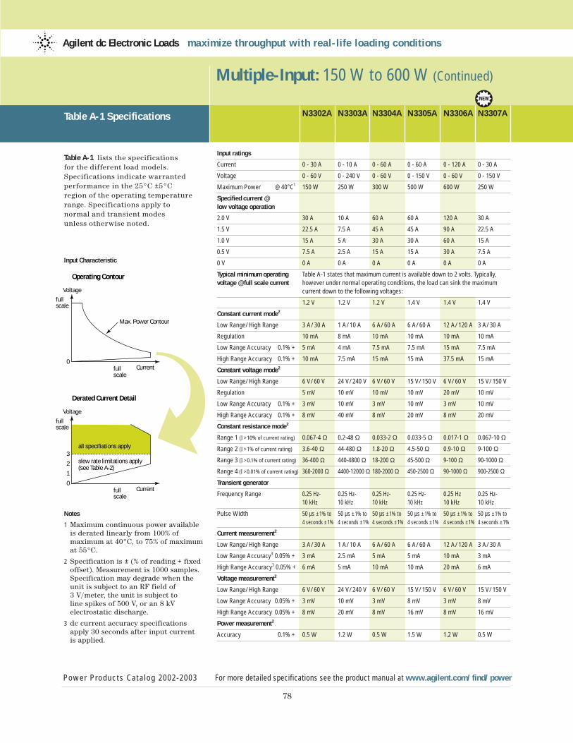
78
Multiple-Input: 150 W to 600 W (Continued)
Table A-1 Specifications
Table A-1 lists the specifications for the different load models.Specifications indicate warranted performance in the 25°C ±5°C region of the operating temperaturerange. Specifications apply to normal and transient modes unless otherwise noted.
Input Characteristic
Notes
1 Maximum continuous power available is derated linearly from 100% of maximum at 40°C, to 75% of maximum at 55°C.
2 Specification is ± (% of reading + fixed offset). Measurement is 1000 samples. Specification may degrade when the unit is subject to an RF field of 3 V/meter, the unit is subject to line spikes of 500 V, or an 8 kV electrostatic discharge.
3 dc current accuracy specifications apply 30 seconds after input current is applied.
N3302A N3303A N3304A N3305A N3306A N3307A
Input ratings
Current 0 - 30 A 0 - 10 A 0 - 60 A 0 - 60 A 0 - 120 A 0 - 30 A
Voltage 0 - 60 V 0 - 240 V 0 - 60 V 0 - 150 V 0 - 60 V 0 - 150 V
Maximum Power @ 40°C1 150 W 250 W 300 W 500 W 600 W 250 W
Specified current @low voltage operation
2.0 V 30 A 10 A 60 A 60 A 120 A 30 A
1.5 V 22.5 A 7.5 A 45 A 45 A 90 A 22.5 A
1.0 V 15 A 5 A 30 A 30 A 60 A 15 A
0.5 V 7.5 A 2.5 A 15 A 15 A 30 A 7.5 A
0 V 0 A 0 A 0 A 0 A 0 A 0 A
Typical minimum operating Table A-1 states that maximum current is available down to 2 volts. Typically, voltage @ full scale current however under normal operating conditions, the load can sink the maximum
current down to the following voltages:
1.2 V 1.2 V 1.2 V 1.4 V 1.4 V 1.4 V
Constant current mode2
Low Range/High Range 3 A/30 A 1 A/10 A 6 A/60 A 6 A/60 A 12 A/120 A 3 A/30 A
Regulation 10 mA 8 mA 10 mA 10 mA 10 mA 10 mA
Low Range Accuracy 0.1% + 5 mA 4 mA 7.5 mA 7.5 mA 15 mA 7.5 mA
High Range Accuracy 0.1% + 10 mA 7.5 mA 15 mA 15 mA 37.5 mA 15 mA
Constant voltage mode2
Low Range/High Range 6 V/60 V 24 V/240 V 6 V/60 V 15 V/150 V 6 V/60 V 15 V/150 V
Regulation 5 mV 10 mV 10 mV 10 mV 20 mV 10 mV
Low Range Accuracy 0.1% + 3 mV 10 mV 3 mV 10 mV 3 mV 10 mV
High Range Accuracy 0.1% + 8 mV 40 mV 8 mV 20 mV 8 mV 20 mV
Constant resistance mode2
Range 1 (I >10% of current rating) 0.067-4 Ω 0.2-48 Ω 0.033-2 Ω 0.033-5 Ω 0.017-1 Ω 0.067-10 Ω
Range 2 (I >1% of current rating) 3.6-40 Ω 44-480 Ω 1.8-20 Ω 4.5-50 Ω 0.9-10 Ω 9-100 Ω
Range 3 (I >0.1% of current rating) 36-400 Ω 440-4800 Ω 18-200 Ω 45-500 Ω 9-100 Ω 90-1000 Ω
Range 4 (I >0.01% of current rating) 360-2000 Ω 4400-12000 Ω 180-2000 Ω 450-2500 Ω 90-1000 Ω 900-2500 Ω
Transient generator
Frequency Range 0.25 Hz- 0.25 Hz- 0.25 Hz- 0.25 Hz- 0.25 Hz 0.25 Hz-10 kHz 10 kHz 10 kHz 10 kHz 10 kHz 10 kHz
Pulse Width 50 µs ±1% to 50 µs ±1% to 50 µs ±1% to 50 µs ±1% to 50 µs ±1% to 50 µs ±1% to
4 seconds ±1% 4 seconds ±1% 4 seconds ±1% 4 seconds ±1% 4 seconds ±1% 4 seconds ±1%
Current measurement2
Low Range/High Range 3 A/30 A 1 A/10 A 6 A/60 A 6 A/60 A 12 A/120 A 3 A/30 A
Low Range Accuracy3 0.05% + 3 mA 2.5 mA 5 mA 5 mA 10 mA 3 mA
High Range Accuracy3 0.05% + 6 mA 5 mA 10 mA 10 mA 20 mA 6 mA
Voltage measurement2
Low Range/High Range 6 V/60 V 24 V/240 V 6 V/60 V 15 V/150 V 6 V/60 V 15 V/150 V
Low Range Accuracy 0.05% + 3 mV 10 mV 3 mV 8 mV 3 mV 8 mV
High Range Accuracy 0.05% + 8 mV 20 mV 8 mV 16 mV 8 mV 16 mV
Power measurement2
Accuracy 0.1% + 0.5 W 1.2 W 0.5 W 1.5 W 1.2 W 0.5 W
Power Products Catalog 2002-2003 For more detailed specifications see the product manual at www.agilent.com/find/power
Agilent dc Electronic Loads maximize throughput with real-life loading conditions
Operating Contour
Voltage
full scale
full scale
Current0
Max. Power Contour
Derated Current Detail
Voltage
full scale
full scale
Current0
1
2
3all specifiations apply
slew rate limitations apply(see Table A-2)
3
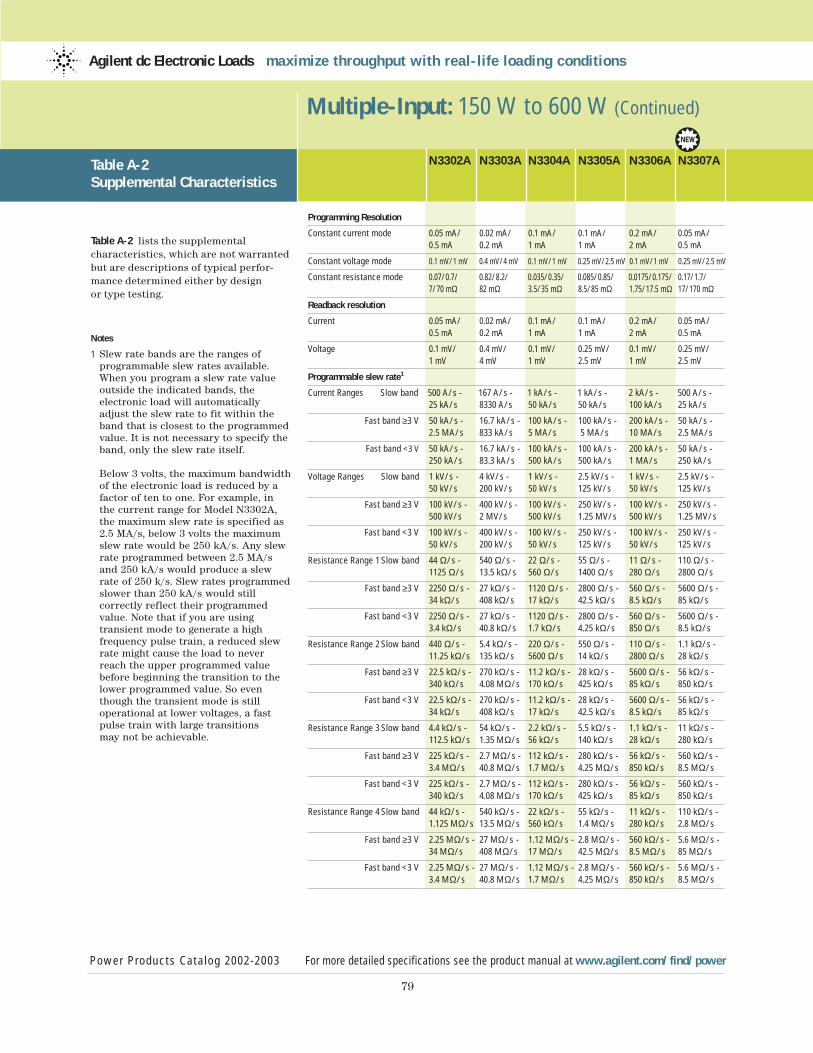
79
Multiple-Input: 150 W to 600 W (Continued)
Table A-2 Supplemental Characteristics
Table A-2 lists the supplemental characteristics, which are not warrantedbut are descriptions of typical perfor-mance determined either by design or type testing.
Notes
1 Slew rate bands are the ranges of programmable slew rates available. When you program a slew rate value outside the indicated bands, the electronic load will automatically adjust the slew rate to fit within the band that is closest to the programmedvalue. It is not necessary to specify theband, only the slew rate itself.
Below 3 volts, the maximum bandwidthof the electronic load is reduced by a factor of ten to one. For example, in the current range for Model N3302A, the maximum slew rate is specified as 2.5 MA/s, below 3 volts the maximum slew rate would be 250 kA/s. Any slew rate programmed between 2.5 MA/s and 250 kA/s would produce a slew rate of 250 k/s. Slew rates programmed slower than 250 kA/s would still correctly reflect their programmed value. Note that if you are using transient mode to generate a high frequency pulse train, a reduced slewrate might cause the load to neverreach the upper programmed value before beginning the transition to the lower programmed value. So even though the transient mode is still operational at lower voltages, a fast pulse train with large transitions may not be achievable.
N3302A N3303A N3304A N3305A N3306A N3307A
Programming Resolution
Constant current mode 0.05 mA/ 0.02 mA/ 0.1 mA/ 0.1 mA/ 0.2 mA/ 0.05 mA/0.5 mA 0.2 mA 1 mA 1 mA 2 mA 0.5 mA
Constant voltage mode 0.1 mV/1 mV 0.4 mV/4 mV 0.1 mV/1 mV 0.25 mV/2.5 mV 0.1 mV/1 mV 0.25 mV/2.5 mV
Constant resistance mode 0.07/0.7/ 0.82/8.2/ 0.035/0.35/ 0.085/0.85/ 0.0175/0.175/ 0.17/1.7/7/70 mΩ 82 mΩ 3.5/35 mΩ 8.5/85 mΩ 1.75/17.5 mΩ 17/170 mΩ
Readback resolution
Current 0.05 mA/ 0.02 mA/ 0.1 mA/ 0.1 mA/ 0.2 mA/ 0.05 mA/ 0.5 mA 0.2 mA 1 mA 1 mA 2 mA 0.5 mA
Voltage 0.1 mV/ 0.4 mV/ 0.1 mV/ 0.25 mV/ 0.1 mV/ 0.25 mV/1 mV 4 mV 1 mV 2.5 mV 1 mV 2.5 mV
Programmable slew rate1
Current Ranges Slow band 500 A/s - 167 A/s - 1 kA/s - 1 kA/s - 2 kA/s - 500 A/s -25 kA/s 8330 A/s 50 kA/s 50 kA/s 100 kA/s 25 kA/s
Fast band ≥3 V 50 kA/s - 16.7 kA/s - 100 kA/s - 100 kA/s - 200 kA/s - 50 kA/s - 2.5 MA/s 833 kA/s 5 MA/s 5 MA/s 10 MA/s 2.5 MA/s
Fast band <3 V 50 kA/s - 16.7 kA/s - 100 kA/s - 100 kA/s - 200 kA/s - 50 kA/s - 250 kA/s 83.3 kA/s 500 kA/s 500 kA/s 1 MA/s 250 kA/s
Voltage Ranges Slow band 1 kV/s - 4 kV/s - 1 kV/s - 2.5 kV/s - 1 kV/s - 2.5 kV/s - 50 kV/s 200 kV/s 50 kV/s 125 kV/s 50 kV/s 125 kV/s
Fast band ≥3 V 100 kV/s - 400 kV/s - 100 kV/s - 250 kV/s - 100 kV/s - 250 kV/s - 500 kV/s 2 MV/s 500 kV/s 1.25 MV/s 500 kV/s 1.25 MV/s
Fast band <3 V 100 kV/s - 400 kV/s - 100 kV/s - 250 kV/s - 100 kV/s - 250 kV/s - 50 kV/s 200 kV/s 50 kV/s 125 kV/s 50 kV/s 125 kV/s
Resistance Range 1 Slow band 44 Ω/s - 540 Ω/s - 22 Ω/s - 55 Ω/s - 11 Ω/s - 110 Ω/s - 1125 Ω/s 13.5 kΩ/s 560 Ω/s 1400 Ω/s 280 Ω/s 2800 Ω/s
Fast band ≥3 V 2250 Ω/s - 27 kΩ/s - 1120 Ω/s - 2800 Ω/s - 560 Ω/s - 5600 Ω/s - 34 kΩ/s 408 kΩ/s 17 kΩ/s 42.5 kΩ/s 8.5 kΩ/s 85 kΩ/s
Fast band <3 V 2250 Ω/s - 27 kΩ/s - 1120 Ω/s - 2800 Ω/s - 560 Ω/s - 5600 Ω/s - 3.4 kΩ/s 40.8 kΩ/s 1.7 kΩ/s 4.25 kΩ/s 850 Ω/s 8.5 kΩ/s
Resistance Range 2 Slow band 440 Ω/s - 5.4 kΩ/s - 220 Ω/s - 550 Ω/s - 110 Ω/s - 1.1 kΩ/s - 11.25 kΩ/s 135 kΩ/s 5600 Ω/s 14 kΩ/s 2800 Ω/s 28 kΩ/s
Fast band ≥3 V 22.5 kΩ/s - 270 kΩ/s - 11.2 kΩ/s - 28 kΩ/s - 5600 Ω/s - 56 kΩ/s - 340 kΩ/s 4.08 MΩ/s 170 kΩ/s 425 kΩ/s 85 kΩ/s 850 kΩ/s
Fast band <3 V 22.5 kΩ/s - 270 kΩ/s - 11.2 kΩ/s - 28 kΩ/s - 5600 Ω/s - 56 kΩ/s - 34 kΩ/s 408 kΩ/s 17 kΩ/s 42.5 kΩ/s 8.5 kΩ/s 85 kΩ/s
Resistance Range 3 Slow band 4.4 kΩ/s - 54 kΩ/s - 2.2 kΩ/s - 5.5 kΩ/s - 1.1 kΩ/s - 11 kΩ/s - 112.5 kΩ/s 1.35 MΩ/s 56 kΩ/s 140 kΩ/s 28 kΩ/s 280 kΩ/s
Fast band ≥3 V 225 kΩ/s - 2.7 MΩ/s - 112 kΩ/s - 280 kΩ/s - 56 kΩ/s - 560 kΩ/s - 3.4 MΩ/s 40.8 MΩ/s 1.7 MΩ/s 4.25 MΩ/s 850 kΩ/s 8.5 MΩ/s
Fast band <3 V 225 kΩ/s - 2.7 MΩ/s - 112 kΩ/s - 280 kΩ/s - 56 kΩ/s - 560 kΩ/s - 340 kΩ/s 4.08 MΩ/s 170 kΩ/s 425 kΩ/s 85 kΩ/s 850 kΩ/s
Resistance Range 4 Slow band 44 kΩ/s - 540 kΩ/s - 22 kΩ/s - 55 kΩ/s - 11 kΩ/s - 110 kΩ/s - 1.125 MΩ/s 13.5 MΩ/s 560 kΩ/s 1.4 MΩ/s 280 kΩ/s 2.8 MΩ/s
Fast band ≥3 V 2.25 MΩ/s - 27 MΩ/s - 1.12 MΩ/s - 2.8 MΩ/s - 560 kΩ/s - 5.6 MΩ/s - 34 MΩ/s 408 MΩ/s 17 MΩ/s 42.5 MΩ/s 8.5 MΩ/s 85 MΩ/s
Fast band <3 V 2.25 MΩ/s - 27 MΩ/s - 1.12 MΩ/s - 2.8 MΩ/s - 560 kΩ/s - 5.6 MΩ/s - 3.4 MΩ/s 40.8 MΩ/s 1.7 MΩ/s 4.25 MΩ/s 850 kΩ/s 8.5 MΩ/s
Power Products Catalog 2002-2003 For more detailed specifications see the product manual at www.agilent.com/find/power
Agilent dc Electronic Loads maximize throughput with real-life loading conditions
3
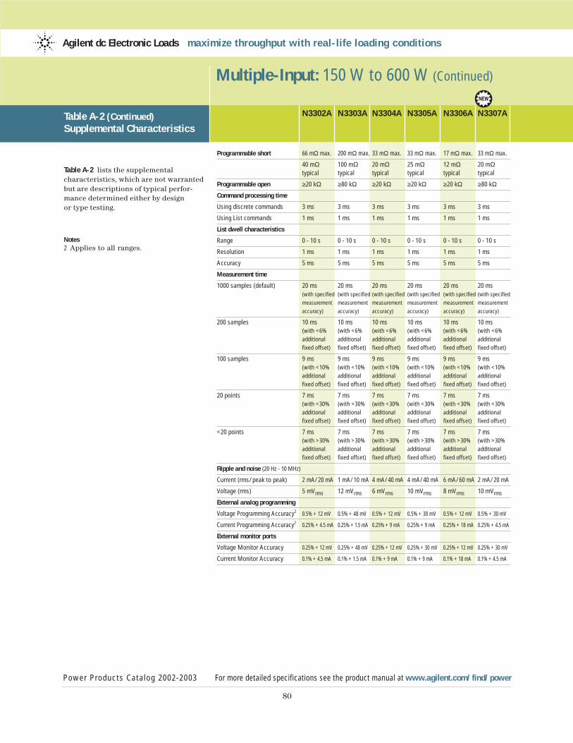
80
Multiple-Input: 150 W to 600 W (Continued)
Table A-2 (Continued)Supplemental Characteristics
Table A-2 lists the supplemental characteristics, which are not warrantedbut are descriptions of typical perfor-mance determined either by design or type testing.
Notes2 Applies to all ranges.
N3302A N3303A N3304A N3305A N3306A N3307A
Programmable short 66 mΩ max. 200 mΩ max. 33 mΩ max. 33 mΩ max. 17 mΩ max. 33 mΩ max.
40 mΩ 100 mΩ 20 mΩ 25 mΩ 12 mΩ 20 mΩtypical typical typical typical typical typical
Programmable open ≥20 kΩ ≥80 kΩ ≥20 kΩ ≥20 kΩ ≥20 kΩ ≥80 kΩ
Command processing time
Using discrete commands 3 ms 3 ms 3 ms 3 ms 3 ms 3 ms
Using List commands 1 ms 1 ms 1 ms 1 ms 1 ms 1 ms
List dwell characteristics
Range 0 - 10 s 0 - 10 s 0 - 10 s 0 - 10 s 0 - 10 s 0 - 10 s
Resolution 1 ms 1 ms 1 ms 1 ms 1 ms 1 ms
Accuracy 5 ms 5 ms 5 ms 5 ms 5 ms 5 ms
Measurement time
1000 samples (default) 20 ms 20 ms 20 ms 20 ms 20 ms 20 ms (with specified (with specified (with specified (with specified (with specified (with specified
measurement measurement measurement measurement measurement measurement
accuracy) accuracy) accuracy) accuracy) accuracy) accuracy)
200 samples 10 ms 10 ms 10 ms 10 ms 10 ms 10 ms(with <6% (with <6% (with <6% (with <6% (with <6% (with <6%
additional additional additional additional additional additional
fixed offset) fixed offset) fixed offset) fixed offset) fixed offset) fixed offset)
100 samples 9 ms 9 ms 9 ms 9 ms 9 ms 9 ms (with <10% (with <10% (with <10% (with <10% (with <10% (with <10%
additional additional additional additional additional additional
fixed offset) fixed offset) fixed offset) fixed offset) fixed offset) fixed offset)
20 points 7 ms 7 ms 7 ms 7 ms 7 ms 7 ms (with <30% (with <30% (with <30% (with <30% (with <30% (with <30%
additional additional additional additional additional additional
fixed offset) fixed offset) fixed offset) fixed offset) fixed offset) fixed offset)
<20 points 7 ms 7 ms 7 ms 7 ms 7 ms 7 ms (with >30% (with >30% (with >30% (with >30% (with >30% (with >30%
additional additional additional additional additional additional
fixed offset) fixed offset) fixed offset) fixed offset) fixed offset) fixed offset)
Ripple and noise (20 Hz - 10 MHz)
Current (rms/peak to peak) 2 mA/20 mA 1 mA/10 mA 4 mA/40 mA 4 mA/40 mA 6 mA/60 mA 2 mA/20 mA
Voltage (rms) 5 mVrms 12 mVrms 6 mVrms 10 mVrms 8 mVrms 10 mVrms
External analog programming
Voltage Programming Accuracy2 0.5% + 12 mV 0.5% + 48 mV 0.5% + 12 mV 0.5% + 30 mV 0.5% + 12 mV 0.5% + 30 mV
Current Programming Accuracy2 0.25% + 4.5 mA 0.25% + 1.5 mA 0.25% + 9 mA 0.25% + 9 mA 0.25% + 18 mA 0.25% + 4.5 mA
External monitor ports
Voltage Monitor Accuracy 0.25% + 12 mV 0.25% + 48 mV 0.25% + 12 mV 0.25% + 30 mV 0.25% + 12 mV 0.25% + 30 mV
Current Monitor Accuracy 0.1% + 4.5 mA 0.1% + 1.5 mA 0.1% + 9 mA 0.1% + 9 mA 0.1% + 18 mA 0.1% + 4.5 mA
Power Products Catalog 2002-2003 For more detailed specifications see the product manual at www.agilent.com/find/power
Agilent dc Electronic Loads maximize throughput with real-life loading conditions
3
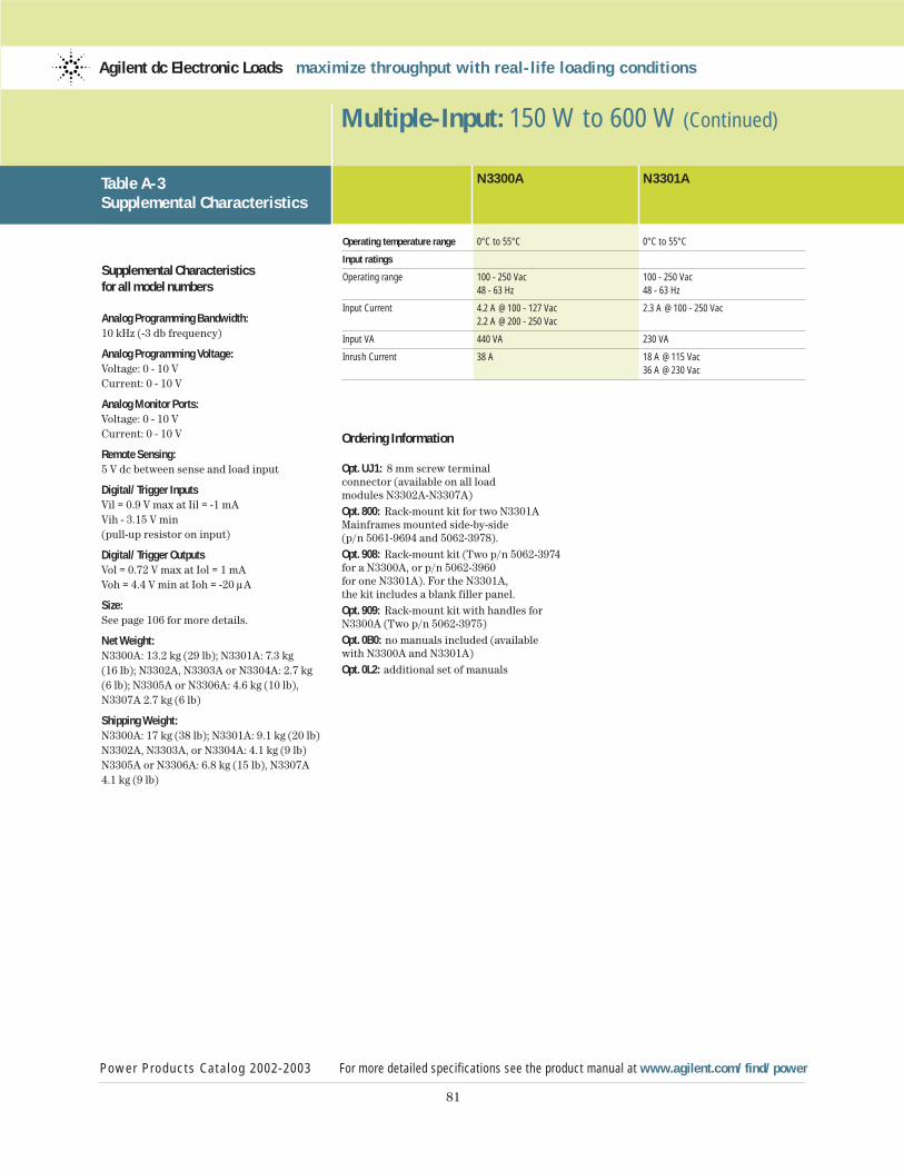
Supplemental Characteristicsfor all model numbers
Analog Programming Bandwidth:10 kHz (-3 db frequency)
Analog Programming Voltage:Voltage: 0 - 10 VCurrent: 0 - 10 V
Analog Monitor Ports:Voltage: 0 - 10 VCurrent: 0 - 10 V
Remote Sensing:5 V dc between sense and load input
Digital/Trigger InputsVil = 0.9 V max at Iil = -1 mAVih - 3.15 V min(pull-up resistor on input)
Digital/Trigger OutputsVol = 0.72 V max at Iol = 1 mAVoh = 4.4 V min at Ioh = -20 µA
Size:See page 106 for more details.
Net Weight:N3300A: 13.2 kg (29 lb); N3301A: 7.3 kg (16 lb); N3302A, N3303A or N3304A: 2.7 kg(6 lb); N3305A or N3306A: 4.6 kg (10 lb),N3307A 2.7 kg (6 lb)
Shipping Weight:N3300A: 17 kg (38 lb); N3301A: 9.1 kg (20 lb)N3302A, N3303A, or N3304A: 4.1 kg (9 lb)N3305A or N3306A: 6.8 kg (15 lb), N3307A4.1 kg (9 lb)
81
Multiple-Input: 150 W to 600 W (Continued)
N3300A N3301A
Operating temperature range 0°C to 55°C 0°C to 55°C
Input ratings
Operating range 100 - 250 Vac 100 - 250 Vac48 - 63 Hz 48 - 63 Hz
Input Current 4.2 A @ 100 - 127 Vac 2.3 A @ 100 - 250 Vac2.2 A @ 200 - 250 Vac
Input VA 440 VA 230 VA
Inrush Current 38 A 18 A @ 115 Vac36 A @ 230 Vac
Power Products Catalog 2002-2003 For more detailed specifications see the product manual at www.agilent.com/find/power
Agilent dc Electronic Loads maximize throughput with real-life loading conditions
Table A-3 Supplemental Characteristics
Ordering Information
Opt. UJ1: 8 mm screw terminal connector (available on all load modules N3302A-N3307A)Opt. 800: Rack-mount kit for two N3301AMainframes mounted side-by-side(p/n 5061-9694 and 5062-3978).Opt. 908: Rack-mount kit (Two p/n 5062-3974for a N3300A, or p/n 5062-3960for one N3301A). For the N3301A,the kit includes a blank filler panel.Opt. 909: Rack-mount kit with handles forN3300A (Two p/n 5062-3975)Opt. 0B0: no manuals included (available with N3300A and N3301A)Opt. 0L2: additional set of manuals
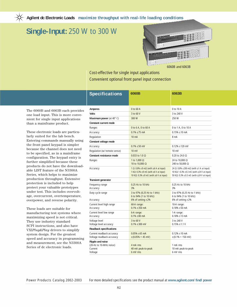
The 6060B and 6063B each providesone load input. This is more conve-nient for single input applicationsthan a mainframe product.
These electronic loads are particu-larly suited for the lab bench.Entering commands manually usingthe front panel keypad is simplerbecause the channel does not needto be specified, as in a mainframeconfiguration. The keypad entry isfurther simplified because theseproducts do not have the download-able LIST feature of the N3300ASeries, which helps to maximizeproduction throughput. Extensiveprotection is included to help protect your valuable prototypesunder test. This includes overvolt-age, overcurrent, overtemperature,overpower, and reverse polarity.
These loads are suitable for manufacturing test systems wheremaximizing speed is not critical.They use industry standard SCPI instructions, and also have VXIPlug&Play drivers to simplifysystem design. For the greatestspeed and accuracy in programmingand measurement, see the N3300ASeries of dc electronic loads.
Agilent dc Electronic Loads maximize throughput with real-life loading conditions
Specif ications 6060B 6063B
Power Products Catalog 2002-2003 For more detailed specifications see the product manual at www.agilent.com/find/power
82
Cost-effective for single input applications
Convenient optional front panel input connection
6060B and 6063B
Single-Input: 250 W to 300 W
Amperes 0 to 60 A 0 to 10 A
Volts 3 to 60 V 3 to 240 V
Maximum power (at 40° C) 300 W 250 W
Constant current mode
Ranges 0 to 6 A, 0 to 60 A 0 to 1 A, 0 to 10 A
Accuracy 0.1% ±75 mA 0.15% ±10 mA
Regulation 10 mA 8 mA
Constant voltage mode
Accuracy 0.1% ±50 mV 0.12% ±120 mV
Regulation (w/remote sense) 10 mV 10 mV
Constant resistance mode 0.033 to 1.0 Ω 0.20 to 24.0 Ω
Ranges 1 to 1,000 Ω 24 to 10,000 Ω10 to 10,000 Ω 240 to 50,000 Ω
Accuracy 1 Ω: 0.8% ±8 mΩ (with ≥6 A at input) 24 Ω: 0.8% ±200 mΩ (with ≥1 A at input)
1 KΩ: 0.3% ±8 mS (with ≥6 V at input) 10 KΩ/: 0.3% ±0.3 mS (with ≥24 V at input)
10 KΩ: 0.3% ±8 mS (with ≥6 V at input) 50 KΩ: 0.3% ±0.3 mS (with ≥24 V at input)
Transient generator
Frequency range 0.25 Hz to 10 kHz 0.25 Hz to 10 kHzAccuracy 3% 3%
Duty cycle range 3 to 97% (0.25 Hz to 1 kHz) 3 to 97% (0.25 Hz to 1 kHz)6 to 94% (1 to 10 kHz) 6 to 94% (1 to 10 kHz)
Accuracy 6% of setting ±2% 6% of setting ±2%
Current level high range 60-A range: 10-A range:Accuracy 0.1% ±350 mA 0.18% ±50 mA
Current level low range 6-A range: 1-A range:Accuracy 0.1% ±80 mA 0.18% ±13 mA
Voltage level 3 to 60 V 3 to 240 VVoltage level accuracy 0.1% ±300 mV 0.15% ±1.1 V
Readback specifications
Current readback accuracy 0.05% ±65 mA 0.12% ±10 mAVoltage readback accuracy ±(0.05% + 45 mV) ±(0.1% + 150 mV)
Ripple and noise(20-Hz to 10-MHz noise) 4 mA rms 1 mA rmsCurrent 40 mA peak-to-peak 10 mA peak-to-peakVoltage 6 mV rms 6 mV rms
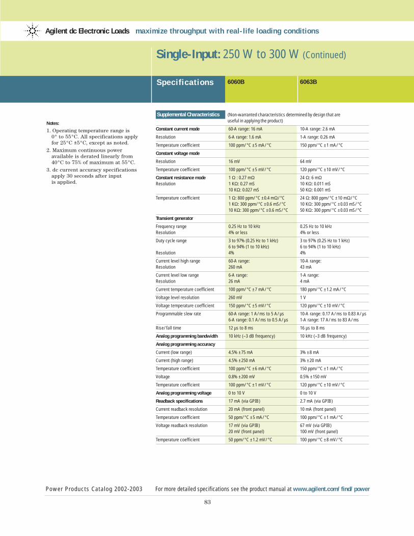
83
Notes:
1. Operating temperature range is 0° to 55°C. All specifications apply for 25°C ±5°C, except as noted.
2. Maximum continuous power available is derated linearly from 40°C to 75% of maximum at 55°C.
3. dc current accuracy specifications apply 30 seconds after input is applied.
Single-Input: 250 W to 300 W (Continued)
Specif ications
Power Products Catalog 2002-2003 For more detailed specifications see the product manual at www.agilent.com/find/power
Agilent dc Electronic Loads maximize throughput with real-life loading conditions
6060B 6063B
Supplemental Characteristics (Non-warranted characteristics determined by design that are useful in applying the product)
Constant current mode 60-A range: 16 mA 10-A range: 2.6 mA
Resolution 6-A range: 1.6 mA 1-A range: 0.26 mA
Temperature coefficient 100 ppm/°C ±5 mA/°C 150 ppm/°C ±1 mA/°C
Constant voltage mode
Resolution 16 mV 64 mV
Temperature coefficient 100 ppm/°C ±5 mV/°C 120 ppm/°C ±10 mV/°C
Constant resistance mode 1 Ω : 0.27 mΩ 24 Ω: 6 mΩResolution 1 KΩ: 0.27 mS 10 KΩ: 0.011 mS
10 KΩ: 0.027 mS 50 KΩ: 0.001 mS
Temperature coefficient 1 Ω: 800 ppm/°C ±0.4 mΩ/°C 24 Ω: 800 ppm/°C ±10 mΩ/°C1 KΩ: 300 ppm/°C ±0.6 mS/°C 10 KΩ: 300 ppm/°C ±0.03 mS/°C10 KΩ: 300 ppm/°C ±0.6 mS/°C 50 KΩ: 300 ppm/°C ±0.03 mS/°C
Transient generator
Frequency range 0.25 Hz to 10 kHz 0.25 Hz to 10 kHzResolution 4% or less 4% or less
Duty cycle range 3 to 97% (0.25 Hz to 1 kHz) 3 to 97% (0.25 Hz to 1 kHz)6 to 94% (1 to 10 kHz) 6 to 94% (1 to 10 kHz)
Resolution 4% 4%
Current level high range 60-A range: 10-A range:Resolution 260 mA 43 mA
Current level low range 6-A range: 1-A range:Resolution 26 mA 4 mA
Current temperature coefficient 100 ppm/°C ±7 mA/°C 180 ppm/°C ±1.2 mA/°C
Voltage level resolution 260 mV 1 V
Voltage temperature coefficient 150 ppm/°C ±5 mV/°C 120 ppm/°C ±10 mV/°C
Programmable slew rate 60-A range: 1 A/ms to 5 A/µs 10-A range: 0.17 A/ms to 0.83 A/µs6-A range: 0.1 A/ms to 0.5 A/µs 1-A range: 17 A/ms to 83 A/ms
Rise/fall time 12 µs to 8 ms 16 µs to 8 ms
Analog programming bandwidth 10 kHz (–3 dB frequency) 10 kHz (–3 dB frequency)
Analog programming accuracy
Current (low range) 4.5% ±75 mA 3% ±8 mA
Current (high range) 4.5% ±250 mA 3% ±20 mA
Temperature coefficient 100 ppm/°C ±6 mA/°C 150 ppm/°C ±1 mA/°C
Voltage 0.8% ±200 mV 0.5% ±150 mV
Temperature coefficient 100 ppm/°C ±1 mV/°C 120 ppm/°C ±10 mV/°C
Analog programming voltage 0 to 10 V 0 to 10 V
Readback specifications 17 mA (via GPIB) 2.7 mA (via GPIB)
Current readback resolution 20 mA (front panel) 10 mA (front panel)
Temperature coefficient 50 ppm/°C ±5 mA/°C 100 ppm/°C ±1 mA/°C
Voltage readback resolution 17 mV (via GPIB) 67 mV (via GPIB)20 mV (front panel) 100 mV (front panel)
Temperature coefficient 50 ppm/°C ±1.2 mV/°C 100 ppm/°C ±8 mV/°C
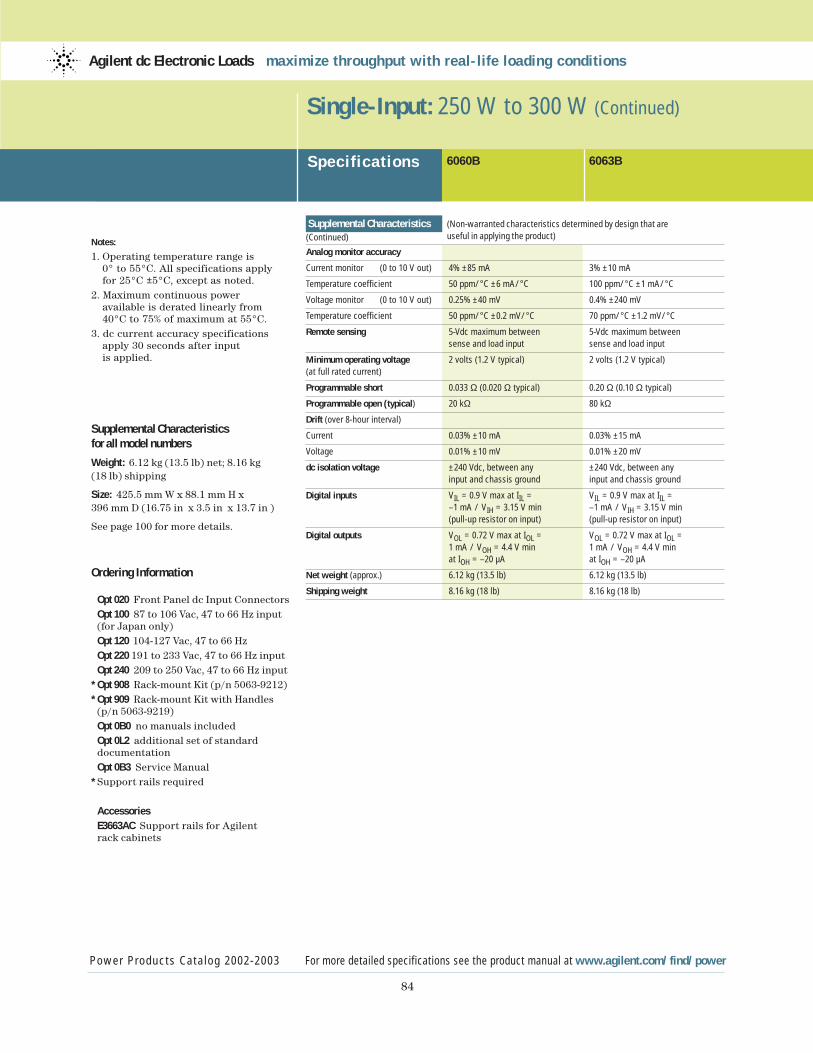
84
Notes:
1. Operating temperature range is 0° to 55°C. All specifications apply for 25°C ±5°C, except as noted.
2. Maximum continuous power available is derated linearly from 40°C to 75% of maximum at 55°C.
3. dc current accuracy specifications apply 30 seconds after input is applied.
Supplemental Characteristicsfor all model numbers
Weight: 6.12 kg (13.5 lb) net; 8.16 kg (18 lb) shipping
Size: 425.5 mm W x 88.1 mm H x 396 mm D (16.75 in x 3.5 in x 13.7 in )
See page 100 for more details.
Ordering Information
Opt 020 Front Panel dc Input ConnectorsOpt 100 87 to 106 Vac, 47 to 66 Hz input(for Japan only)Opt 120 104-127 Vac, 47 to 66 HzOpt 220 191 to 233 Vac, 47 to 66 Hz inputOpt 240 209 to 250 Vac, 47 to 66 Hz input
* Opt 908 Rack-mount Kit (p/n 5063-9212)* Opt 909 Rack-mount Kit with Handles
(p/n 5063-9219)Opt 0B0 no manuals included Opt 0L2 additional set of standard documentationOpt 0B3 Service Manual
* Support rails required
AccessoriesE3663AC Support rails for Agilent rack cabinets
Single-Input: 250 W to 300 W (Continued)
Specif ications
Power Products Catalog 2002-2003 For more detailed specifications see the product manual at www.agilent.com/find/power
Agilent dc Electronic Loads maximize throughput with real-life loading conditions
6060B 6063B
Supplemental Characteristics (Non-warranted characteristics determined by design that are
(Continued) useful in applying the product)
Analog monitor accuracy
Current monitor (0 to 10 V out) 4% ±85 mA 3% ±10 mA
Temperature coefficient 50 ppm/°C ±6 mA/°C 100 ppm/°C ±1 mA/°C
Voltage monitor (0 to 10 V out) 0.25% ±40 mV 0.4% ±240 mV
Temperature coefficient 50 ppm/°C ±0.2 mV/°C 70 ppm/°C ±1.2 mV/°C
Remote sensing 5-Vdc maximum between 5-Vdc maximum between sense and load input sense and load input
Minimum operating voltage 2 volts (1.2 V typical) 2 volts (1.2 V typical)(at full rated current)
Programmable short 0.033 Ω (0.020 Ω typical) 0.20 Ω (0.10 Ω typical)
Programmable open (typical) 20 kΩ 80 kΩ
Drift (over 8-hour interval)
Current 0.03% ±10 mA 0.03% ±15 mA
Voltage 0.01% ±10 mV 0.01% ±20 mV
dc isolation voltage ±240 Vdc, between any ±240 Vdc, between any input and chassis ground input and chassis ground
Digital inputs VIL = 0.9 V max at IIL = VIL = 0.9 V max at IIL = –1 mA / VIH = 3.15 V min –1 mA / VIH = 3.15 V min (pull-up resistor on input) (pull-up resistor on input)
Digital outputs VOL = 0.72 V max at IOL = VOL = 0.72 V max at IOL = 1 mA / VOH = 4.4 V min 1 mA / VOH = 4.4 V min at IOH = –20 µA at IOH = –20 µA
Net weight (approx.) 6.12 kg (13.5 lb) 6.12 kg (13.5 lb)
Shipping weight 8.16 kg (18 lb) 8.16 kg (18 lb)
Power Products Catalog 2002-2003 www.agilent.com/find/power
85
Agilent Technologies
Basic dc Power Supplies...essential features for a tight budget
Performance dc Power Supplies...speed and accuracy for test optimization
Application Specific dc Power Supplies...Tailored solutions for specific needs
dc Electronic Loads...maximize throughput with real life loading conditions
ac Power Source/Analyzers...an integrated ac power solution
ac PowerSource/Analyzers
Agilent ac Power Source/Analyzers provide a completeac test solution. As ac sources,they combine the capabilitiesof a power amplifier and anarbitrary waveform generator.This allows you to simulatenormal waveforms and manytypes of distorted power wave-forms. The built-in power ana-lyzer combines the capabilitiesof a multimeter, oscilloscope,harmonic analyzer and poweranalyzer. These instrumentsmay also be used to producedc power, either alone or as a dc offset to an ac waveform.
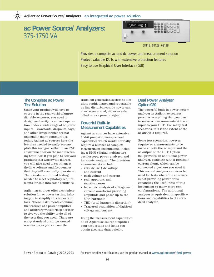
The Complete ac Power Test SolutionSince your product will have to operate in the real world of unpre-dictable ac power, you need todesign and verify its correct opera-tion under a wide range of ac powerinputs. Brownouts, dropouts, sags,and other irregularities are notunusual in many communitiestoday. Agilent ac sources have thefeatures needed to easily accom-plish this test goal either in an R&Denvironment or on the manufactur-ing test floor. If you plan to sell yourproducts in a worldwide market,you will also need to test them atthe line voltages and frequenciesthat they will eventually operate at.There is also additional testingneeded to meet regulatory require-ments for sale into some countries.
Agilent ac sources offer a completesolution for ac power testing, help-ing you to simplify this importanttask. These instruments combinethe features of a power amplifierand arbitrary waveform generatorto give you the ability to do all of the tests that you need. There aremany standard preprogrammedwaveforms, or you can use the
transient generation system to sim-ulate sophisticated and repeatable ac line disturbances. dc power canalso be generated, either as a dc offset or as a pure dc signal.
Powerful Built-inMeasurement CapabilitiesAgilent ac sources have extensive16-bit precision measurement capabilities which would normallyrequire a number of complex measurement instruments, includ-ing a DMM (digital multimeter),oscilloscope, power analyzer, and harmonic analyzer. The precisionmeasurements include:• rms, dc, ac + dc voltage
and current• peak voltage and current• real, apparent, and
reactive power• harmonic analysis of voltage and
current waveforms providing amplitude and phase up to the 50th harmonic
• THD (total harmonic distortion)• Triggered acquisition of digitized
voltage and current
Using the measurement capabilitiesof an Agilent ac source simplifiesyour test setups and helps youobtain accurate data quickly.
Dual Power Analyzer Option 020The powerful built-in power meter/analyzer in Agilent ac sources provides everything that you needto make ac measurements at the acinput to your DUT. For many testscenarios, this is the extent of theac analysis required.
Some test scenarios, however,require ac measurements to bemade at both the ac input and theac output of the DUT. Option 020 provides an additional power analyzer, complete with a precisioncurrent shunt, which can be connected anywhere you need it.This second analyzer can even beused for tests where the ac sourceis not providing power, thusexpanding the usefulness of thisinstrument to many more test configurations. The additional analyzer is equivalent in specifica-tions and capabilities to the stan-dard analyzer.
Agilent ac Power Source/Analyzers an integrated ac power solution
Power Products Catalog 2002-2003 For more detailed specifications see the product manual at www.agilent.com/find/power
86
Provides a complete ac and dc power and measurement solution
Protect valuable DUTs with extensive protection features
Easy to use Graphical User Interface (GUI)
6811B, 6812B, 6813B
ac Power Source/Analyzers:375-1750 VA

87
Using the dual power analyzeroption instead of an additionalpower analyzer instrument exter-nally is more than just convenient.Measurements on all four measure-ment channels (ac source outputvoltage and current, and dual poweranalyzer voltage and current inputs)are inherently synchronized withthe ac source output waveform.This precision would be difficult to achieve using separate measure-ment instruments.
Examples Dual Power AnalyzerApplications• Complete testing of
uninterruptible power sources (UPS)
• Efficiency testing of dc power supplies
• Efficiency testing of ac power sources
• Efficiency testing of transformers• Safety testing of transformers• Line disturbance and brownout
testing of dc power supplies• Line disturbance and brownout
testing of ac power sources• Sleep mode current monitoring• Independent power analyzer
Sleep Mode Current MonitoringMany electronic products havepower-saving or sleep modes. Inthis mode, the device draws onlyenough power to be able to recog-nize a “wake-up” signal, and thenexecute a smooth “wake-up”. Thepower drawn in this mode is a criti-cal parameter, and the ability toaccurately monitor it is important.
The accessory precision currentshunt that is supplied with option020 is mounted in such a way tomake it easy for you to replace itwith a precision resistor of yourchoice. By doing this, you can configure the system to accuratelymonitor extremely low currents.This provides an easy way for youto profile the current draw in allmodes of your product’s operation.Since Agilent 6811B-6813B acsources produce dc power as wellas ac power, portable battery oper-ated products can also be testedwith this configuration.
UPS (uninterruptible power source) TestingThe Dual Power Analyzer Optionprovides many important benefitsfor UPS testing. Since the key to correct UPS operation is having theoutput react properly to changes onthe input, being able to monitor theoutput relative to the input simpli-fies testing. For example, commandsare available to enable calculation of UPS transfer time, and the phasedifference between the UPS inputand output voltage. Agilent acsources also have programmable output impedance, enabling the UPS designer to verify product stability over a wide range of ac line impedance.
Free Graphical User Interface (GUI)When you need to run a variety of tests, study the results carefully, and then run more tests with slightlyvaried conditions, writing computerprograms using the extensive SCPIcommand set may seem burdensome.This is when you should downloadthe latest copy of the Free Agilent acSource Graphical User Interfacefrom www.agilent.com.
The Agilent ac source GUI makes itquick and easy to set the output ofyour Agilent ac source, be it from astored waveform or with a waveformthat you create using your mouse.The GUI also allows you to see theoutput of the ac source in graphicalform, save the results, or dump themdirectly into a Microsoft Excel file.
Microsoft Excel LinkThe direct Excel link feature wasrecently added to meet the currentneeds of R&D engineers. It makes it easy to keep the results of manytests, and makes them easily retriev-able. With it, the test records result-ing from changing conditions can be kept in one place and easily compared.
Access to raw data often helps infully understanding test results. Forexample, small local peaks may notbe evident in processed data. V, I and phase results from harmonicmeasurements are particularly susceptible to not showing the complete story in a graphical representation.
ac Power Source/Analyzers: 375-1750 VA (Continued)
Power Products Catalog 2002-2003 For more detailed specifications see the product manual at www.agilent.com/find/power
Agilent ac Power Source/Analyzers an integrated ac power solution
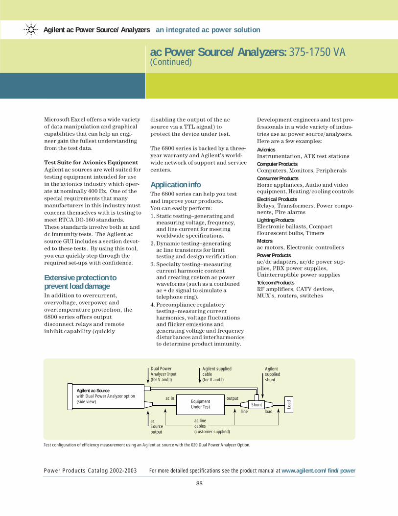
88
ac Power Source/Analyzers: 375-1750 VA (Continued)
Power Products Catalog 2002-2003 For more detailed specifications see the product manual at www.agilent.com/find/power
Agilent ac Power Source/Analyzers an integrated ac power solution
Microsoft Excel offers a wide varietyof data manipulation and graphicalcapabilities that can help an engi-neer gain the fullest understandingfrom the test data.
Test Suite for Avionics EquipmentAgilent ac sources are well suited fortesting equipment intended for usein the avionics industry which oper-ate at nominally 400 Hz. One of thespecial requirements that manymanufacturers in this industry mustconcern themselves with is testing tomeet RTCA DO-160 standards.These standards involve both ac anddc immunity tests. The Agilent acsource GUI includes a section devot-ed to these tests. By using this tool,you can quickly step through therequired set-ups with confidence.
Extensive protection to prevent load damageIn addition to overcurrent, overvoltage, overpower andovertemperature protection, the6800 series offers output disconnect relays and remoteinhibit capability (quickly
disabling the output of the acsource via a TTL signal) to protect the device under test.
The 6800 series is backed by a three-year warranty and Agilent’s world-wide network of support and servicecenters.
Application infoThe 6800 series can help you test and improve your products.You can easily perform:1. Static testing–generating and
measuring voltage, frequency, and line current for meeting worldwide specifications.
2. Dynamic testing–generating ac line transients for limit testing and design verification.
3. Specialty testing–measuring current harmonic content and creating custom ac power waveforms (such as a combined ac + dc signal to simulate a telephone ring).
4. Precompliance regulatory testing–measuring current harmonics, voltage fluctuations and flicker emissions and generating voltage and frequency disturbances and interharmonics to determine product immunity.
Development engineers and test pro-fessionals in a wide variety of indus-tries use ac power source/analyzers.Here are a few examples:
AvionicsInstrumentation, ATE test stationsComputer ProductsComputers, Monitors, PeripheralsConsumer ProductsHome appliances, Audio and videoequipment, Heating/cooling controlsElectrical ProductsRelays, Transformers, Power compo-nents, Fire alarmsLighting ProductsElectronic ballasts, Compact flourescent bulbs, TimersMotorsac motors, Electronic controllersPower Productsac/dc adapters, ac/dc power sup-plies, PBX power supplies,Uninterruptible power suppliesTelecom ProductsRF amplifiers, CATV devices,MUX’s, routers, switches
Dual PowerAnalyzer Input (for V and I)
Agilent suppliedcable(for V and I)
ac in output
line load
Agilent supplied shunt
acSourceoutput
LoadShunt
ac linecables(customer supplied)
EquipmentUnder Test
Agilent ac Sourcewith Dual Power Analyzer option(side view)
Test configuration of efficiency measurement using an Agilent ac source with the 020 Dual Power Analyzer Option.
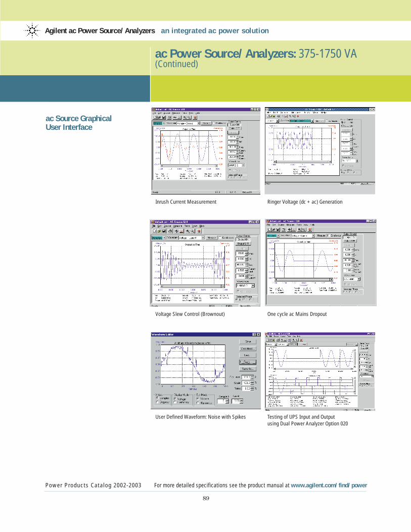
89
ac Power Source/Analyzers: 375-1750 VA (Continued)
Power Products Catalog 2002-2003 For more detailed specifications see the product manual at www.agilent.com/find/power
Agilent ac Power Source/Analyzers an integrated ac power solution
ac Source Graphical User Interface
Inrush Current Measurement Ringer Voltage (dc + ac) Generation
Voltage Slew Control (Brownout) One cycle ac Mains Dropout
User Defined Waveform: Noise with Spikes Testing of UPS Input and Output using Dual Power Analyzer Option 020
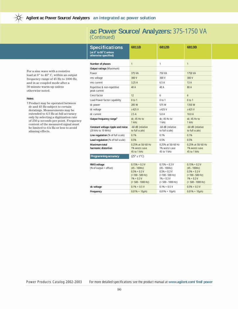
90
For a sine wave with a resistive load at 0° to 40° C, within an output frequency range of 45 Hz to 1000 Hz,and in ac coupled mode after a 30 minute warm-up unless otherwise noted.
Notes:
1 Product may be operated between dc and 45 Hz subject to certain deratings. Measurements may be extended to 4.5 Hz at full accuracy only by selecting a digitization rate of 250 µ seconds per point. Frequency content of the measured signal must be limited to 4 k Hz or less to avoid aliasing effects.
ac Power Source/Analyzers: 375-1750 VA (Continued)
Power Products Catalog 2002-2003 For more detailed specifications see the product manual at www.agilent.com/find/power
Agilent ac Power Source/Analyzers an integrated ac power solution
Specif ications(at 0˚ to 55˚C unless otherwise specified)
6811B 6812B 6813B
Number of phases 1 1 1
Output ratings (Maximum)
Power 375 VA 750 VA 1750 VA
rms voltage 300 V 300 V 300 V
rms current 3.25 A 6.5 A 13 A
Repetitive & non-repetitive 40 A 40 A 80 Apeak current
Crest factor 12 6 6
Load Power factor capability 0 to 1 0 to 1 0 to 1
dc power 285 W 575 W 1350 W
dc voltage ±425 V ±425 V ±425 V
dc current 2.5 A 5.0 A 10.0 A
Output frequency range1 dc; 45 Hz to dc; 45 Hz to dc; 45 Hz to1 kHz 1 kHz 1 kHz
Constant voltage ripple and noise -60 dB (relative -60 dB (relative -60 dB (relative(20 kHz to 10 MHz) to full scale) to full scale) to full scale)
Line regulation (% of full scale) 0.1% 0.1% 0.1%
Load regulation (% of full scale) 0.5% 0.5% 0.5%
Maximum total 0.25% at 50/60 Hz 0.25% at 50/60 Hz 0.25% at 50/60 Hzharmonic distortion 1% worst case 1% worst case 1% worst case
45 to 1 kHz 45 to 1 kHz 45 to 1 kHz
Programming accuracy (25° ± 5°C)
RMS voltage 0.15% + 0.3 V 0.15% + 0.3 V 0.15% + 0.3 V(% of output + offset) (45 - 100Hz) (45 - 100Hz) (45 - 100Hz)
0.5% + 0.3 V 0.5% + 0.3 V 0.5% + 0.3 V(>100 - 500 Hz) (>100 - 500 Hz) (>100 - 500 Hz)1% + 0.3 V 1% + 0.3 V 1% + 0.3 V(> 500 - 1000 Hz) (> 500 - 1000 Hz) (> 500 - 1000 Hz)
dc voltage 0.1% + 0.5 V 0.1% + 0.5 V 0.5% + 0.3 V
Frequency 0.01% + 10µHz 0.01% + 10µHz 0.01% + 10µHz
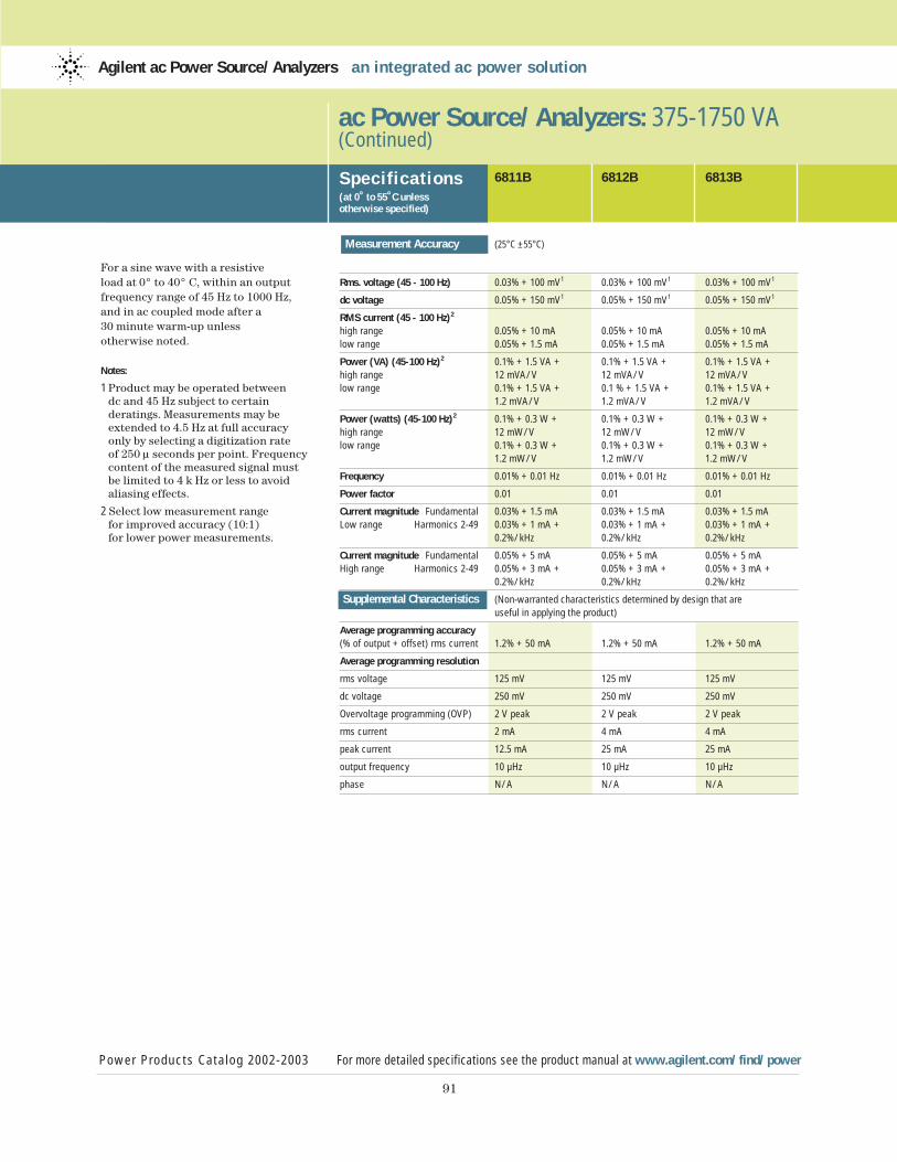
91
For a sine wave with a resistive load at 0° to 40° C, within an output frequency range of 45 Hz to 1000 Hz,and in ac coupled mode after a 30 minute warm-up unless otherwise noted.
Notes:
1 Product may be operated between dc and 45 Hz subject to certain deratings. Measurements may be extended to 4.5 Hz at full accuracy only by selecting a digitization rate of 250 µ seconds per point. Frequency content of the measured signal must be limited to 4 k Hz or less to avoid aliasing effects.
2 Select low measurement range for improved accuracy (10:1) for lower power measurements.
ac Power Source/Analyzers: 375-1750 VA (Continued)
Specif ications(at 0˚ to 55˚C unless otherwise specified)
Power Products Catalog 2002-2003 For more detailed specifications see the product manual at www.agilent.com/find/power
Agilent ac Power Source/Analyzers an integrated ac power solution
6811B 6812B 6813B
Measurement Accuracy (25°C ±55°C)
Rms. voltage (45 - 100 Hz) 0.03% + 100 mV1 0.03% + 100 mV1 0.03% + 100 mV1
dc voltage 0.05% + 150 mV1 0.05% + 150 mV1 0.05% + 150 mV1
RMS current (45 - 100 Hz)2
high range 0.05% + 10 mA 0.05% + 10 mA 0.05% + 10 mAlow range 0.05% + 1.5 mA 0.05% + 1.5 mA 0.05% + 1.5 mA
Power (VA) (45-100 Hz)2 0.1% + 1.5 VA + 0.1% + 1.5 VA + 0.1% + 1.5 VA +high range 12 mVA/V 12 mVA/V 12 mVA/Vlow range 0.1% + 1.5 VA + 0.1 % + 1.5 VA + 0.1% + 1.5 VA +
1.2 mVA/V 1.2 mVA/V 1.2 mVA/V
Power (watts) (45-100 Hz)2 0.1% + 0.3 W + 0.1% + 0.3 W + 0.1% + 0.3 W +high range 12 mW/V 12 mW/V 12 mW/Vlow range 0.1% + 0.3 W + 0.1% + 0.3 W + 0.1% + 0.3 W +
1.2 mW/V 1.2 mW/V 1.2 mW/V
Frequency 0.01% + 0.01 Hz 0.01% + 0.01 Hz 0.01% + 0.01 Hz
Power factor 0.01 0.01 0.01
Current magnitude Fundamental 0.03% + 1.5 mA 0.03% + 1.5 mA 0.03% + 1.5 mALow range Harmonics 2-49 0.03% + 1 mA + 0.03% + 1 mA + 0.03% + 1 mA +
0.2%/kHz 0.2%/kHz 0.2%/kHz
Current magnitude Fundamental 0.05% + 5 mA 0.05% + 5 mA 0.05% + 5 mAHigh range Harmonics 2-49 0.05% + 3 mA + 0.05% + 3 mA + 0.05% + 3 mA +
0.2%/kHz 0.2%/kHz 0.2%/kHz
Supplemental Characteristics (Non-warranted characteristics determined by design that are useful in applying the product)
Average programming accuracy(% of output + offset) rms current 1.2% + 50 mA 1.2% + 50 mA 1.2% + 50 mA
Average programming resolution
rms voltage 125 mV 125 mV 125 mV
dc voltage 250 mV 250 mV 250 mV
Overvoltage programming (OVP) 2 V peak 2 V peak 2 V peak
rms current 2 mA 4 mA 4 mA
peak current 12.5 mA 25 mA 25 mA
output frequency 10 µHz 10 µHz 10 µHz
phase N/A N/A N/A

92
For a sine wave with a resistive load at 0° to 40° C, within an output frequency range of 45 Hz to 1000 Hz,and in ac coupled mode after a 30 minute warm-up unless otherwise noted.
ac Input Ratings notes:
1 Measured at low line
2 Measured at high line
Ordering Information
Opt 019 2000 VA ac Power source/analyzer (6813B only)Opt 020 Dual power analyzer optionOpt 026 26 Volt, 0.1A auxiliary reference output (6812B only)Opt 0BN Service Manual, extra Operating Guide, and ProgrammingGuideOpt 1CM Rack-mount Kit, p/n 5062-3977 (quantity 2)(support rails required)Opt 1CP Rack-mount Kit with Handles, p/n 5062-3983 (support rails required) 6811B, 6812B, 6813B onlySupport rails, p/n 12679B, required when rack mounting the 6811B, 6812B, and 6813B Opt 1CM and Opt 1CP
Opt 100 (6811B and 6812B only) 87 to 106 Vac (100 Vac nominal), 47-63 Hz, Japan onlyOpt 120 104-127 Vac (120 Vac nominal), 47-63 HzOpt 200 (6813B only) 174-220 Vac (200 Vac nominal), 47-63 Hz, Japan onlyOpt 208 (6811B and 6812B only) 174 to 220 Vac (208 Vac nominal), 47-63 HzOpt 230 191 to 254 Vac (230 Vac nominal), 24-63 HzOpt 831 12 AWG, 200 to 240 Vac, unterminated (6812B, 6813B only)Opt 832 4 mm2 wire size, unterminated (6813B only)Opt 833 1.5 mm2 wire size, 200 to 240 Vac, unterminated (6812B only)Opt 834 10 AWG, 100 to 120 Vac, unterminated (6812B only)
ac Power Source/Analyzers: 375-1750 VA (Continued)
Specif ications(at 0˚ to 55˚C unless otherwise specified)
Power Products Catalog 2002-2003 For more detailed specifications see the product manual at www.agilent.com/find/power
Agilent ac Power Source/Analyzers an integrated ac power solution
6811B 6812B 6813B
Supplemental Characteristics (Non-warranted characteristics determined by design that are
(Continued) useful in applying the product)
Average measurement resolution
rms voltage 10 mV 10 mV 10 mV
rms current 2 mA 2 mA 2 mA
Programmable output impedance
resistance 0-1 Ω 0-1 Ω 0-1 Ω
inductance 20 µh - 1 mh 20 µh - 1 mh 20 µh - 1 mh
Remote sense capability Up to 1 Vrms can be Up to 1 Vrms can be Up to 1 Vrms can be dropped across each dropped across each dropped across each load lead. load lead. load lead.
Isolation to ground 300 Vrms/425 Vdc 300 Vrms/425 Vdc 300 Vrms/425 Vdc
Net weight 28.2 kg (62 lb) 28.2 kg (62 lb) 32.7 kg (72 lb)
Shipping weight 31.8 kg (70 lb) 31.8 kg (70 lb) 36.4 kg (80 lb)
Dimensions See drawings on page 105
ac Input Ratings
Voltage range (Vac) 87 to 106 Vac 87 to 106 Vac 174 to 220 Vac*default factory setting *104 to 127 Vac *104 to 127 Vac *191 to 254 Vac
174 to 220 Vac 174 to 220 Vac191 to 254 Vac 191 to 254 Vac
Maximum input current (rms)1 12 A (100 Vac) 28 A (100 Vac) 22 A (200/208 Vac)10 A (120 Vac) 24 A (120 Vac)7.5 A (200/208 Vac) 15 A (200/208 Vac) 20 A (230 Vac)6.5 A (230 Vac) 13 A (230 Vac)
Input power (max)2 1000 VA/700 W 2500 VA/1400 W 3800 VA/2600 W
Input frequency 47 to 63 Hz 47 to 63 Hz 47 to 63 Hz
Opt 841 Line Cord with NEMA L6-20P; 20 A 250 V Plug (6812B only)Opt 842 Line Cord with IEC 309; 32 A 220 V plug (6813B only)Opt 844 Line Cord with NEMA L6-30P; 30 A 250 V Locking Plug (6813B only)Opt 845 Line Cord with IEC 309; 16 A 220 V Plug (6812B only)Opt 846 Line Cord with NEMA L6-30P; 30 A 120 V Plug (6812B only)Opt 847 Line Cord with CEE 7/7; 16 A 220 V Plug (6812B only)Opt 848 Line Cord with BS 546; 15 A 240 V Plug (6812B only)For ac Line Cord and Cord Options information see pages 93-98.
Note
If no line cord option is specified forproducts which require 800 series linecords, an unterminated line cord will beshipped automatucally for the destina-tion country on your purchase order.
Agilent Technologies
Power Products Catalog 2002-2003 For more detailed specifications see the product manual at www.agilent.com/find/power
93
Choosing ac Line Voltage and Cord Options for your Agilent Power Products
7 Easy Steps for Choosing Line Cord Options
Determine the voltage option
Step 1 Go to table 1a. Find the model number of the product you are ordering.Note the standard line voltage. If it is correct you do not need to specify aline voltage option. Go to step 4
Step 2 If the standard line voltage is not correct, use table 1b to determine whichof the available options best matches the available line voltage.
Step 3 Add the line voltage option to your purchase order.
Line cords for low power products
Step 4Go to table 1a. Find the correct line cord option series for the product youare ordering. If your model # requires an 800 series, go to step 6.
Step 5If your model # requires a 900 series line cord, the correct one will auto-matically be shipped for the destination country on the purchase order.DONE!
Line cords for high power products
Step 6 If your model number requires an 800 series line cord, determine if thereis a line cord with plug that matches your outlet receptacle in tables 3aand b. If not, choose the appropriate unterminated line cord.
Step 7 Add the option number for the appropriate line cord to your purchaseorder. DONE!
E
L N
ELN
E
LN
EL N
E
L N
E
L N
A sample of our many line cord options
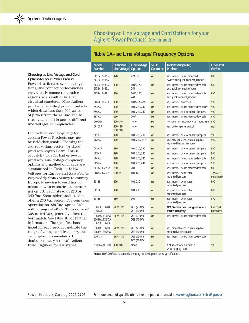
94
Choosing ac Line Voltage and CordOptions for your Power ProductPower distribution systems, regula-tions, and connection techniquesvary greatly among geographicregions as a result of local acelectrical standards. Most Agilentproducts, including power productswhich draw less than 500 watts of power from the ac line, can bereadily adjusted to accept differentline voltages or frequencies.
Line voltage and frequency for certain Power Products may not be field changeable. Choosing thecorrect voltage option for theseproducts requires care. This is especially true for higher powerproducts. Line voltage/frequencyoptions and method of change aresummarized in Table 1a below.Voltages for Europe and Asia Pacificvary widely from country to country.Europe is moving toward harmo-nization, with countries standardiz-ing on 230 Vac instead of 220 or 240 Vac. Some older products don’toffer a 230 Vac option. For countriesoperating on 230 Vac, option 240with a range of +6%/-13% (a range of208 to 254 Vac) generally offers thebest match. See table 1b for furtherinformation. The specifications listed for each product indicate therange of voltage and frequency thateach option accomodates. If indoubt, contact your local AgilentField Engineer for assistance.
Choosing ac Line Voltage and Cord Options for your Agilent Power Products (Continued)
Power Products Catalog 2002-2003 For more detailed specifications see the product manual at www.agilent.com/find/power
Agilent Technologies
Model Standard Line Voltage 50 HZ Field Changeable; Line CordNumber Line Voltage Options Operation Method Series
6010A, 6011A, 120 220, 240 Yes Yes; internal board mounted 8006012A, 6015A switch and quick connect jumpers
6030A, 6031A, 120 100*, 220, Yes Yes; internal board mounted switch 800 6032A, 6035A 240 and quick connect jumpers
6033A, 6038A 120 100*, 220, Yes Yes; internal board mounted switch 900240 and quick connect jumpers
6060B, 6063B 120 100*, 220, 240 Yes Yes; internal switches 900
654XA 120 100, 220, 240 Yes Yes; internal board mounted switches 900
655XA 120 100, 220, 240 Yes Yes; internal quick connect jumpers 900
657XA 230 200* Yes Yes; internal board mounted switch 800
66000A 100-240 none Yes Not necessary; automatic wide ranging input 800
6610XA 100-120, none Yes Yes; bottom panel switch n.a.200-240
661XC 120 100, 220, 230 Yes Yes; internal quick connect jumpers 900
662XA 120 100, 220, 240 Yes Yes; moveable insert on rear panel 900mounted line cord module
663XXA 120 100, 220, 230 Yes Yes; internal quick connect jumpers 900
663XB 120 100, 220, 230 Yes Yes; internal quick connect jumpers 900
664XA 120 100, 220, 240 Yes Yes; internal board mounted switch 900
665XA 120 100, 220, 240 Yes Yes; internal quick connect jumpers 900
667XA, E4356A 230 200 Yes Yes; internal board mounted switch 800
668XA, 669XA 220 3Ø 400 3Ø Yes Yes; internal connector 3Ø; unter-
mounted jumpers minated only
6811B 120 100, 230 Yes Yes; internal connector 900mounted jumpers
6812B 120 100, 230 Yes Yes; internal connector 800mounted jumpers
6813B 230 200 Yes Yes; internal connector 800mounted jumpers
E3610A, E3611A, ØEM (115) ØE3 (230 V), Yes NO! Transformer change required; line cord E3612A ØE9 (100 V) return to factory hardwired
E3614A, E3615A, ØEM (115) ØE3 (230 V), Yes Yes; internal board mounted switchE3616A, E3617A, ØE9 (100 V) E3620A, E3630A
E3631A, E3632A, ØEM (115) ØE3 (230 V), Yes Yes: moveable insert on rear panel E3633A, E3634A ØE9 (100 V) mounted ac receptacle
E364XA ØEM (115) ØE3 (230 V), Yes Yes, internal board mounted switchØE9 (100 V)
N3300A, N3301A 100-240 None Yes Not necessary; automatic 900wide ranging input
Notes: 100*, 200*: for Japan only; derating required, product see specifications
Table 1A– ac Line Voltage/Frequency Options
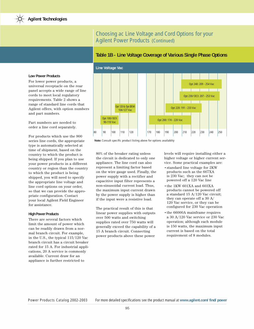
95
Low Power Products
For lower power products, a universal receptacle on the rearpanel accepts a wide range of linecords to meet local regulatoryrequirements. Table 2 shows arange of standard line cords thatAgilent offers, with option numbersand part numbers.
Part numbers are needed to order a line cord separately.
For products which use the 900series line cords, the appropriatetype is automatically selected attime of shipment, based on thecountry to which the product isbeing shipped. If you plan to useyour power products in a differentcountry or region than the countryto which the product is beingshipped, you will need to specify the appropriate line voltage andline cord options on your order, so that we can provide the appro-priate configuration. Contact your local Agilent Field Engineerfor assistance.
High Power Products
There are several factors whichlimit the amount of power whichcan be readily drawn from a nor-mal branch circuit. For example, in the U.S., the typical 115/120 Vacbranch circuit has a circuit breakerrated for 15 A. For industrial appli-cations, 20 A service is commonlyavailable. Current draw for anappliance is further restricted to
Choosing ac Line Voltage and Cord Options for your Agilent Power Products (Continued)
Power Products Catalog 2002-2003 For more detailed specifications see the product manual at www.agilent.com/find/power
Agilent Technologies
80 90 100 110 120 170 180 190 200 210 220 230 240 250
Note: Consult specific product listing above for options availablity
Opt 100/0E9: 90-110 Vac
Opt 120 & Opt ØEM:104-127 Vac
Opt 200: 174 - 220 Vac
Opt 220: 191 - 233 Vac
Opt 230/OE3: 207 - 253 Vac
Opt 240: 209 - 254 Vac
Table 1B - Line Voltage Coverage of Various Single Phase Options
Line Voltage Vac
80% of the breaker rating unless the circuit is dedicated to only oneappliance. The line cord can alsorepresent a limiting factor based on the wire gauge used. Finally, thepower supply with a rectifier andcapacitive input filter represents anon-sinusoidal current load. Thus,the maximum input current drawnby the power supply is higher thanif the input were a resistive load.
The practical result of this is thatlinear power supplies with outputsover 500 watts and switching supplies rated over 750 watts willgenerally exceed the capability of a15 A branch circuit. Connectingpower products above these power
levels will require installing either ahigher voltage or higher current ser-vice. Some practical examples are:•standard line voltage for 2KW
products such as the 667XA is 230 Vac; they can not be powered off a 120 Vac line
•the 1KW 601XA and 603XA products cannot be powered off a standard 15 A/120 Vac circuit; they can operate off a 30 A/120 Vac service, or they can be configured for 230 Vac operation
•the 66000A mainframe requires a 30 A/120 Vac service or 230 Vac operation; although each module is 150 watts, the maximum input current is based on the total requirement of 8 modules.
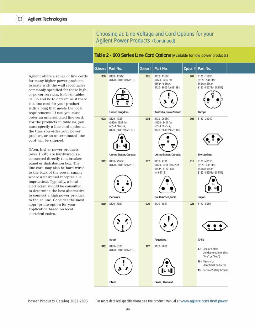
EL N
EL NE
LN
E
L N
E
LN
E
L N
E
LN
E
L N
E LN
E
LN
E
LN
96
Agilent offers a range of line cordsfor many higher power productsto mate with the wall receptacles commonly specified for these high-er power services. Refer to tables3a, 3b and 3c to determine if thereis a line cord for your productwith a plug that meets the localrequirements. If not, you mustorder an unterminated line cord.For the products in table 3a, youmust specify a line cord option atthe time you order your powerproduct, or an unterminated linecord will be shipped.
Often, higher power products(over 1 kW) are hardwired, i.e.connected directly to a breakerpanel or distribution box. The line cord may also be hard wiredto the back of the power supplywhere a universal receptacle isimpractical. Typically, a local electrician should be consulted to determine the best alternativeto connect a high power productto the ac line. Consider the mostappropriate option for your application based on local electrical codes.
Choosing ac Line Voltage and Cord Options for your Agilent Power Products (Continued)
Power Products Catalog 2002-2003 For more detailed specifications see the product manual at www.agilent.com/find/power
Agilent Technologies
Table 2 - 900 Series Line Cord Options (Available for low power products)
Option # Part No. Option # Part No. Option # Part No.
900 8120 - 1351C 901 8120 - 1369C 902 8120 - 1689C (8120 - 8605 for 6811B) (8120 - 5412 for (8120 - 5413 for
655xA/665xA, 655xA/665xA,8120 - 8606 for 6811B) 8120 - 8607 for 6811B)
United Kingdom Australia, New Zealand Europe
903 8120 - 4383 904 8120 - 0698C 906 8120 - 2104C (8120 - 4383 for (8120 - 5421 for 655xA/665xA, 665xA/665xA,8120 - 8609 for 6811B) 8120 - 8610 for 6811B)
United States, Canada United States, Canada Switzerland
912 8120 - 2956C 917 8120 - 4211 918 8120 - 4753C (8120 - 8608 for 6811B) (8120 - 5414 for 655xA, (8120 - 4383 for
665xA, 8120 - 8611 655xA/665xA for 6811B) 8120 - 8609 for 6811B)
Denmark South Africa, India Japan
919 8120 - 6800 920 8120 - 6869 921 8120 - 6980
Israel Argentina Chile
922 8120 - 8376 927 8120 - 8871(8120 - 8800 for 6611B)
China Brazil, Thailand
L = Line or Active Conductor (also called ”live“ or ”hot“)
N = Neutral or identified Conductor
E = Earth or Safety Ground
E
L N
ELN
EL N
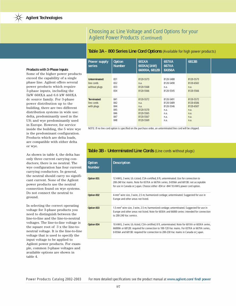
97
Choosing ac Line Voltage and Cord Options for your Agilent Power Products (Continued)
Power Products Catalog 2002-2003 For more detailed specifications see the product manual at www.agilent.com/find/power
Agilent Technologies
Table 3A - 800 Series Line Cord Options (Available for high power products)
Power supply Option 601XA 657XA 6813Bseries Number 603XA(1kW) 667XA
66000A, 6812B E4356A
Unterminated: 831 8120-5573 8120-5488 8120-5573
line cords 832 n.a. 8120-5490 8120-6502
without plugs 833 8120-5568 n.a. n.a.
834 8120-5566 8120-5545 8120-5566
Terminated: 841 8120-5572 8120-5491 8120-5572line cords 842 n.a. 8120-5489 8120-6506with plugs 844 n.a. 8120-5546 8120-6507
845 8120-5570 n.a. n.a.846 8120-5565 n.a. n.a.847 8120-5567 n.a. n.a.848 8120-5569 n.a. n.a.
NOTE: If no line cord option is specified on the purchase order, an unterminated line cord will be shipped.
Table 3B - Unterminated Line Cords (Line cords without plugs)
Option DescriptionNumber
Option 831 12 AWG, 3 wire; UL-Listed, CSA-certified, 8 ft, unterminated. Use for connection to
200-240 Vac mains. Note for 657XA or 667XA series, E4356A and 6813B: not acceptable
for use in Canada or Japan. Choose either -834 or -844 10 AWG power cord option.
Option 832 4-mm2 wire size, 3 wire, 2.5 m; harmonized cordage; unterminated. Suggested for use in
Europe and other areas not listed.
Option 833 1.5-mm2 wire size, 3 wire, 2.5 m; harmonized cordage; unterminated. Suggested for use in
Europe and other areas not listed. Note for 603XA and 66000 series: intended for connection
to 200-240 Vac service.
Option 834 10 AWG, 3 wire; UL-listed, CSA-certified; 8 ft, unterminated. Note for 601XA or 603XA series,
66000A or 6812B: required for connection to 100-120 Vac mains. For 657XA or 667XA series,
E4356A and 6813B: required for connection to 200-230 Vac mains in Canada or Japan.
Products with 3-Phase InputsSome of the higher power productsexceed the capability of a singlephase line. Agilent offers severalpower products which require 3-phase inputs, including the 5kW 668XA and 6.6 kW 669XA dc source family. For 3-phasepower distribution up to the building, there are two differentdistribution systems in wide use:delta, predominantly used in theUS; and wye predominantly used in Europe. However, for serviceinside the building, the 5 wire wyeis the predominant configuration.Products which are delta loads,are compatible with either delta or wye.
As shown in table 4, the delta hasonly three current carrying con-ductors; there is no neutral. Thewye configuration has four currentcarrying conductors. In general,the neutral should carry no signifi-cant current. None of the Agilentpower products use the neutralconnection found on wye systems.Do not connect the neutral toground.
In selecting the correct operatingvoltage for 3-phase products youneed to distinguish between theline-to-line and the line-to-neutralvoltages. The line-to-line voltage isthe square root of 3 x the line-to-neutral voltage. It is the line-to-linevoltage that is used to specify theinput voltage to be applied toAgilent power products. For exam-ple, common 3-phase voltages andavailable options are shown intable 4.
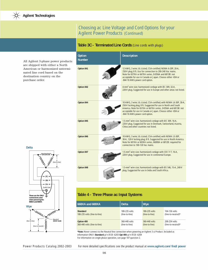
98
Choosing ac Line Voltage and Cord Options for your Agilent Power Products (Continued)
Power Products Catalog 2002-2003 For more detailed specifications see the product manual at www.agilent.com/find/power
Agilent Technologies
Table 3C - Terminated Line Cords (Line cords with plugs)
Option DescriptionNumber
Option 841 12 AWG, 3 wire; UL-Listed, CSA-certified; NEMA 6-20P, 20-A, 250-V plug; 8 ft. Use for connection to 200-240 Vac mains. Note for 657XA or 667XA series, E4356A and 6813B: not acceptable for use in Canada or Japan. Choose either -834 or -844 10 AWG power cord option.
Option 842 4-mm2 wire size; harmonized cordage with IEC 309, 32-A, 220-V plug. Suggested for use in Europe and other areas not listed.
Option 844 10 AWG, 3 wire; UL-Listed, CSA-certified; with NEMA L6-30P, 30-A, 250-V locking plug; 8 ft. Suggested for use in North and South America. Note for 657XA or 667XA series, E4356A and 6813B: not acceptable for use in Canada or Japan. Choose either -834 or -844 10 AWG power cord option.
Option 845 1.5-mm2 wire size; harmonized cordage with IEC 309, 16-A, 220-V plug. Suggested for use in Denmark, Switzerland, Austria, China and other countries not listed.
Option 846 10 AWG, 3 wire; UL-Listed, CSA-certified; with NEMA L5-30P, 30-A, 120-V locking plug; 8 ft. Suggested for use in North America. Note for 601XA or 603XA series, 66000A or 6812B: required for connection to 100-120 Vac mains.
Option 847 1.5-mm2 wire size; harmonized cordage with CEE 7/7, 16-A, 220-V plug. Suggested for use in continental Europe.
Option 848 1.5-mm2 wire size; harmonized cordage with BS 546, 15-A, 240-Vplug. Suggested for use in India and South Africa.
All Agilent 3-phase power productsare shipped with either a NorthAmerican or harmonized untermi-nated line cord based on the destination country on the purchase order.
Table 4 - Three Phase ac Input Systems
668XA and 669XA Delta Wye
Standard 180-235 volts 180-235 volts 104-136 volts180-235 volts (line-to-line) (line-to-line) (line-to-line) (line-to-neutral)*
Option 400 360-440 volts 360-440 volts 208-254 volts360-440 volts (line-to-line) (line-to-line) (line-to-line) (line-to-neutral)*
*Note: Never connect to the Neutral line connection when powering an Agilent 3 f Product. Included asinformation ONLY. Standard: p/n 8120 -6203 Opt 400: p/n 8120 -6204For information on single-phase operation, see page 107 question 2.
These are the ONLY
connections used
when powering the
668XA and 669XA
Earth Gnd
V(line-to-neutral)
Neutral(never used)
V(line-to-line)
V(line-to-line)
OC
OB
OA
Delta
Wye
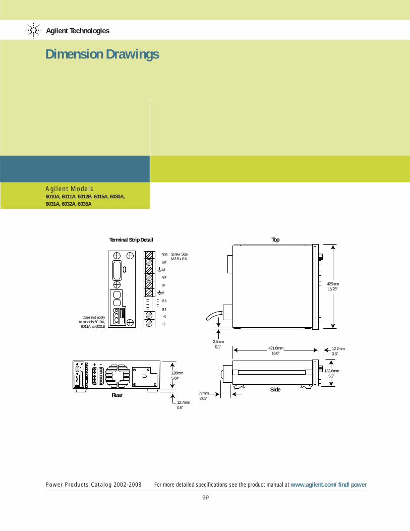
Agi lent Models6010A, 6011A, 6012B, 6015A, 6030A, 6031A, 6032A, 6035A
Agilent Technologies
Power Products Catalog 2002-2003 For more detailed specifications see the product manual at www.agilent.com/find/power
99
Dimension Drawings
Size0.6
128mm5.04"
12.7mm0.5"
425mm16.75"
132.6mm5.2"
12.7mm0.5"
421.6mm16.6"
77mm3.03"
2.5mm0.1"
RearSide
TopTerminal Strip Detail
Does not applyto models 6010A,
6011A, & 6021B
Screw SizeM3.5 x 0.6
VM
IM
M
VP
IP
P
B6
B1
+S
-S
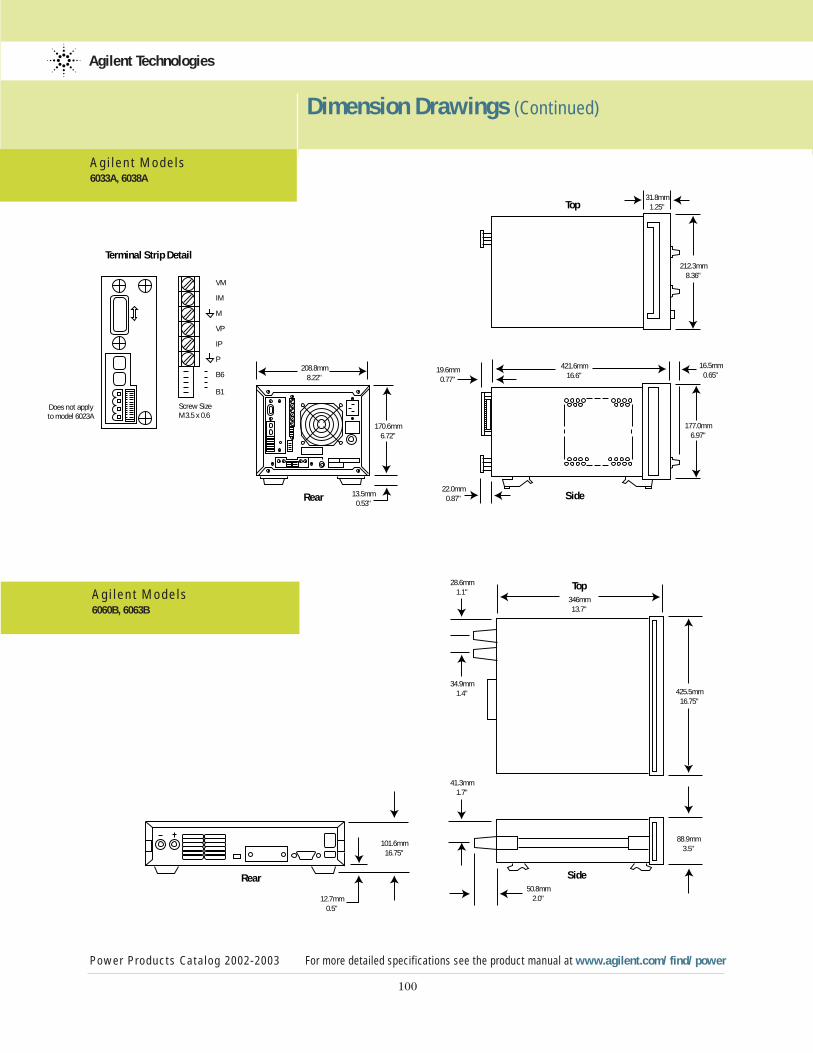
100
Dimension Drawings (Continued)
Power Products Catalog 2002-2003 For more detailed specifications see the product manual at www.agilent.com/find/power
Agilent Technologies
Agi lent Models6033A, 6038A
Agi lent Models6060B, 6063B
212.3mm8.36"
421.6mm16.6"
16.5mm0.65"
22.0mm0.87"
19.6mm0.77"
177.0mm6.97"
31.8mm1.25"Top
SideRear
170.6mm6.72"
13.5mm0.53"
208.8mm8.22"
Terminal Strip Detail
Does not applyto model 6023A
Screw SizeM3.5 x 0.6
VM
IM
M
VP
IP
P
B6
B1
425.5mm16.75"
28.6mm1.1"
34.9mm1.4"
346mm13.7"
88.9mm3.5"
50.8mm2.0"
41.3mm1.7"
Top
Side
101.6mm16.75"
12.7mm0.5"
Rear
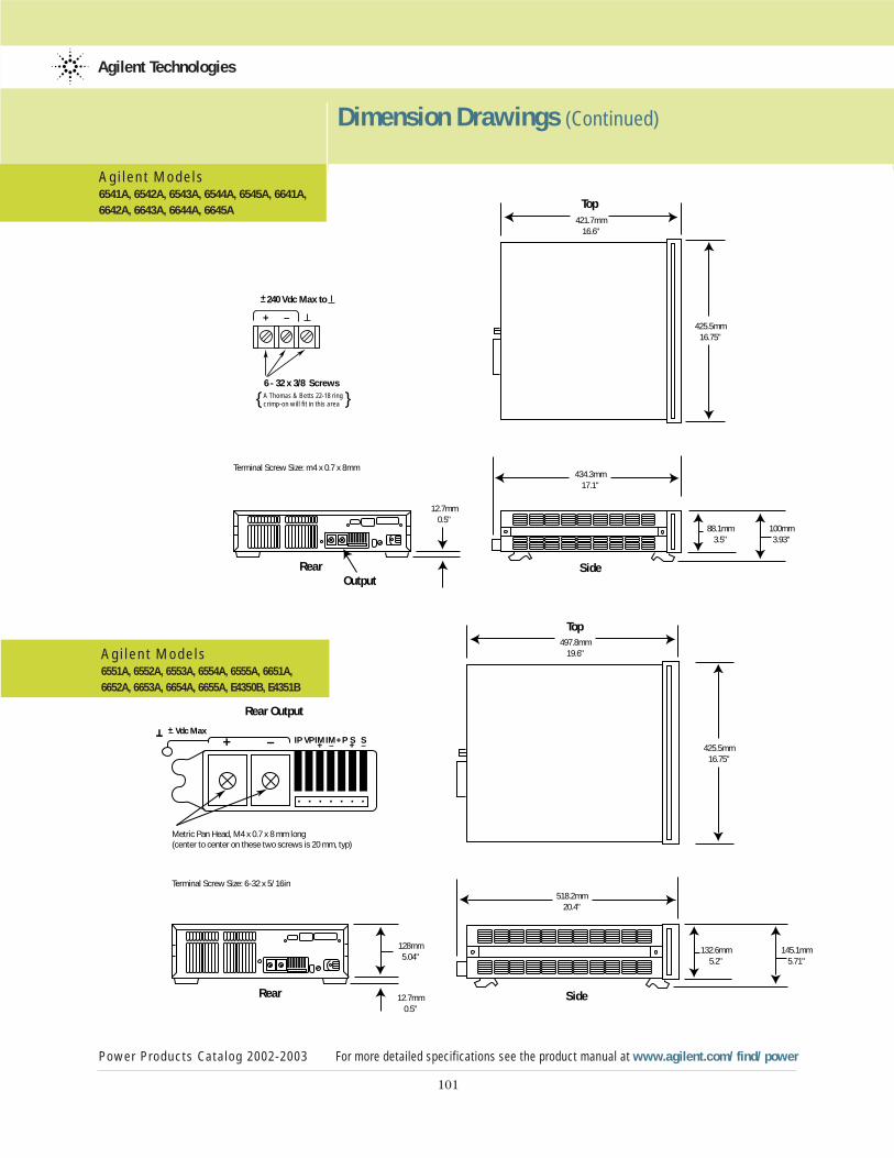
101
Dimension Drawings (Continued)
Power Products Catalog 2002-2003 For more detailed specifications see the product manual at www.agilent.com/find/power
Agilent Technologies
Agi lent Models6541A, 6542A, 6543A, 6544A, 6545A, 6641A, 6642A, 6643A, 6644A, 6645A
Agi lent Models6551A, 6552A, 6553A, 6554A, 6555A, 6651A, 6652A, 6653A, 6654A, 6655A, E4350B, E4351B
Top
SideRearOutput
434.3mm17.1"
425.5mm16.75"
421.7mm16.6"
88.1mm3.5"
100mm3.93"
12.7mm0.5"
Terminal Screw Size: m4 x 0.7 x 8mm
A Thomas & Betts 22-18 ring crimp-on will fit in this area
240 Vdc Max to
6 - 32 x 3/8 Screws
+–
+ –
425.5mm16.75"
497.8mm19.6"
518.2mm20.4"
128mm5.04"
12.7mm0.5"
132.6mm5.2"
145.1mm5.71"
Terminal Screw Size: 6-32 x 5/16in
Metric Pan Head, M4 x 0.7 x 8 mm long(center to center on these two screws is 20 mm, typ)
–
Top
SideRear
Rear Output
Vdc Max
+ IP+ –
+
+ –– VP IMIM+P S S
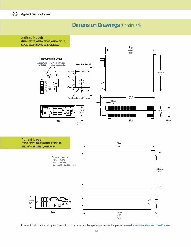
102
Dimension Drawings (Continued)
Power Products Catalog 2002-2003 For more detailed specifications see the product manual at www.agilent.com/find/power
Agilent Technologies
Agi lent Models6571A, 6572A, 6573A, 6574A, 6575A, 6671A, 6672A, 6673A, 6674A, 6675A, E4356A
Agi lent Models6611C, 6612C, 6613C, 6614C, 66309B/D,66311B/D, 66319B/D, 66321B/D
425.5mm16.75"
574mm22.6"
640mm25.4"
68mm2.67"
132.6mm5.2"
145.1mm5.71"
Top
Side12.7mm
0.5"
128mm5.04"
Accepts WireAWG 12-22
1/4" x 1" untreadedhole on each bussbar
Note: Buss Bar is 1/8" thick cu
1.25"
0.75"
0.31 dia"
1.0 "
0.5 "
IMVP+IP-IP+P+S-S
-LS +LS
Rear
Rear Connector Detail
Buss Bar Detail
Top
Side
*
435mm17.13"
212.8mm8.4"
88.13.
Rear
88.1mm3.5"
* 66309 B/D, 66311 B/D: 435mm (17.13")66312A: 444.4mm (17.5")6611C-6614C: 368.3mm (14.5")
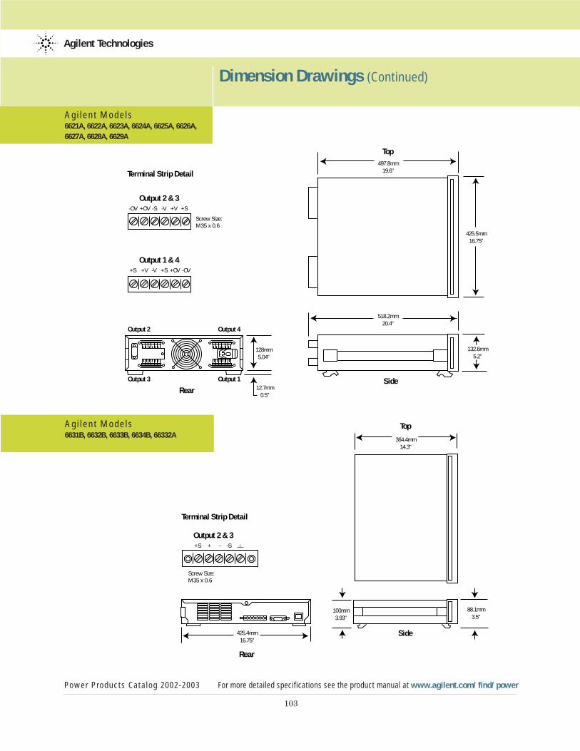
103
Dimension Drawings (Continued)
Power Products Catalog 2002-2003 For more detailed specifications see the product manual at www.agilent.com/find/power
Agilent Technologies
Agi lent Models6621A, 6622A, 6623A, 6624A, 6625A, 6626A,6627A, 6628A, 6629A
Agi lent Models6631B, 6632B, 6633B, 6634B, 66332A
Output 2 Output 4
Output 3 Output 1
Top
Terminal Strip Detail
Output 2 & 3
SideRear
Output 1 & 4
425.5mm16.75"
497.8mm19.6"
518.2mm20.4"
128mm5.04"
-OV +OV -S -V +V +S
+S +V -V +S +OV -OV
12.7mm0.5"
132.6mm5.2"
Screw Size: M35 x 0.6
Terminal Strip Detail
Output 2 & 3
Top
Side
Rear
364.4mm14.3"
100mm3.93"
425.4mm16.75"
+S + - -S
88.1mm3.5"
Screw Size: M35 x 0.6

104
Dimension Drawings (Continued)
Power Products Catalog 2002-2003 For more detailed specifications see the product manual at www.agilent.com/find/power
Agilent Technologies
Agi lent Models6680A, 6681A, 6682A, 6683A, 6684A, 6690A,6691A, 6692A
Agi lent Models66000A
SideOutput Buss Bars
Top
12.7mm0.5"
28.6mm1.13"
30.2mm1.19"
65.1mm2.56"
27.8mm1.09"
9.5mm0.38" 12.7mm
0.5"
674.7mm26.56"
667.3mm26.27"
574mm22.6"
221.5mm8.75"
425.5mm16.75"
+
–
Buss Bar Detail
Rear
3/8" Diameter (6)
3 3/4"
Top
Front
677.9mm26.69"
104.9mm4.13"
425.7mm16.76"
177.3mm6.98"
190mm7.5"
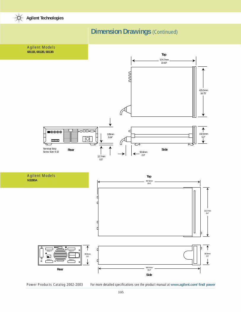
105
Dimension Drawings (Continued)
Power Products Catalog 2002-2003 For more detailed specifications see the product manual at www.agilent.com/find/power
Agilent Technologies
Agi lent Models6811B, 6812B, 6813B
Agi lent ModelsN3280A
574.7mm22.63"
425.5mm16.75"
12.7mm0.5"
50.8mm2.0"
128mm5.04"
Terminal StripScrew Size: 6-32
132.6mm5.2"
Rear
Top
Side
212.7mm8.4"
494.4mm19.4"
497.8mm19.6"
88.9mm3.5"
88.9mm3.5"
Output 1
Output 4
Output 2
Output 3
Rear
Side
Top
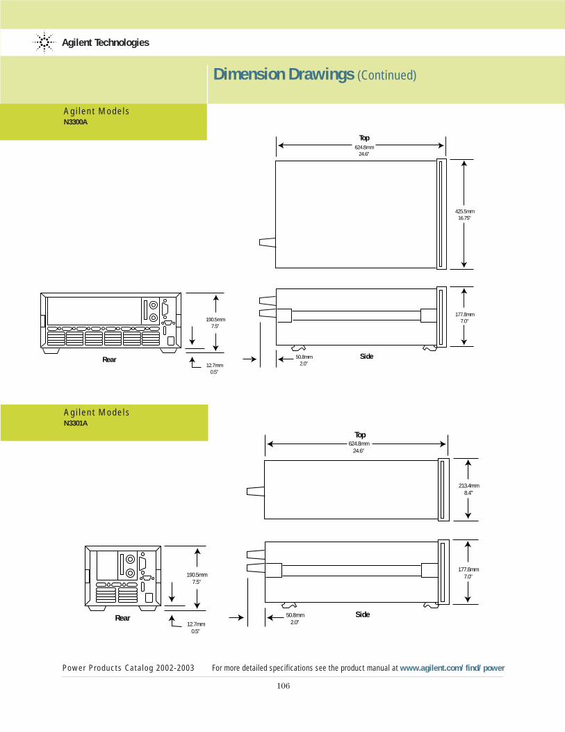
106
Dimension Drawings (Continued)
Power Products Catalog 2002-2003 For more detailed specifications see the product manual at www.agilent.com/find/power
Agilent Technologies
Agi lent ModelsN3300A
Agi lent ModelsN3301A
425.5mm16.75"
624.8mm24.6"
177.8mm7.0"
50.8mm2.0"
190.5mm7.5"
12.7mm0.5"
Top
SideRear
213.4mm8.4"
624.8mm24.6"
177.8mm7.0"
50.8mm2.0"
190.5mm7.5"
12.7mm0.5"
Top
SideRear
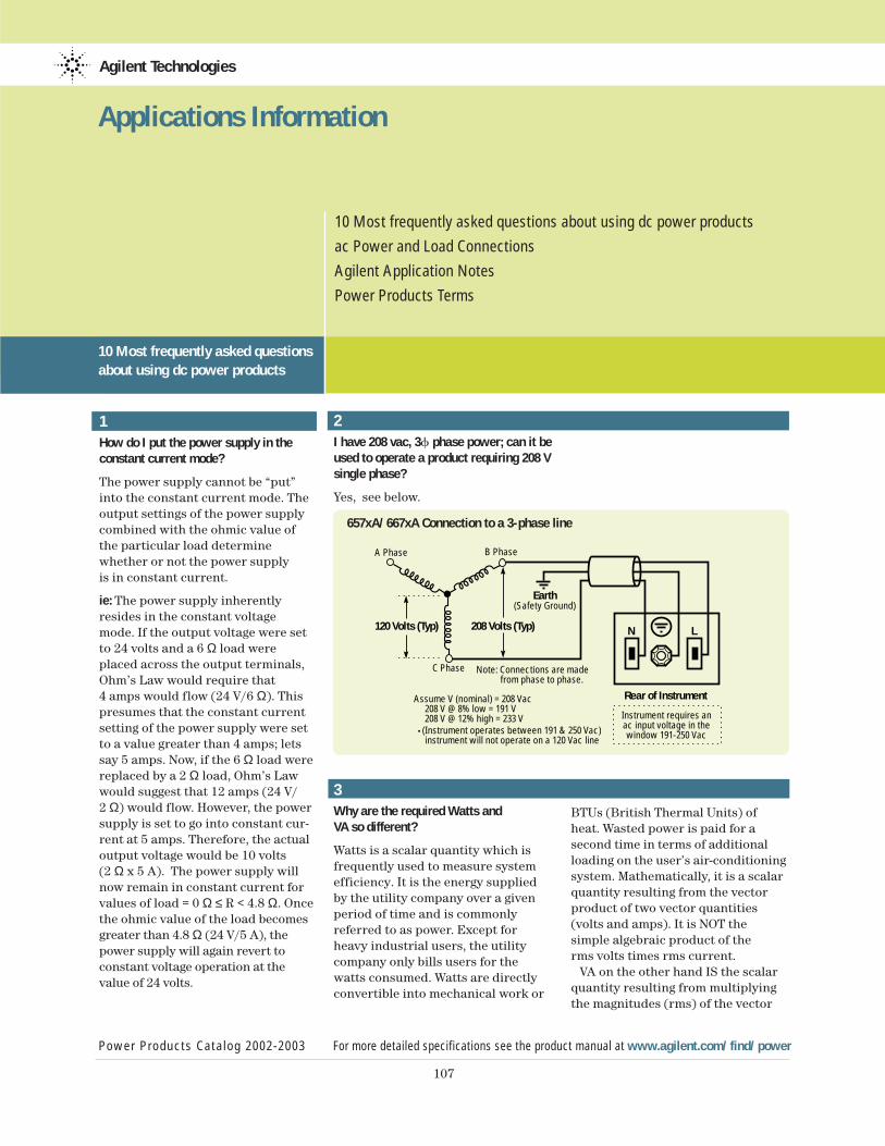
1How do I put the power supply in theconstant current mode?
The power supply cannot be “put”into the constant current mode. Theoutput settings of the power supplycombined with the ohmic value ofthe particular load determinewhether or not the power supply is in constant current.
ie: The power supply inherentlyresides in the constant voltagemode. If the output voltage were setto 24 volts and a 6 Ω load wereplaced across the output terminals,Ohm’s Law would require that 4 amps would flow (24 V/6 Ω). Thispresumes that the constant currentsetting of the power supply were setto a value greater than 4 amps; letssay 5 amps. Now, if the 6 Ω load werereplaced by a 2 Ω load, Ohm’s Lawwould suggest that 12 amps (24 V/ 2 Ω) would flow. However, the powersupply is set to go into constant cur-rent at 5 amps. Therefore, the actualoutput voltage would be 10 volts (2 Ω x 5 A). The power supply willnow remain in constant current forvalues of load = 0 Ω ≤ R < 4.8 Ω. Oncethe ohmic value of the load becomesgreater than 4.8 Ω (24 V/5 A), thepower supply will again revert to constant voltage operation at thevalue of 24 volts.
Agilent Technologies
Power Products Catalog 2002-2003 For more detailed specifications see the product manual at www.agilent.com/find/power
107
Applications Information
2I have 208 vac, 3f phase power; can it beused to operate a product requiring 208 Vsingle phase?
Yes, see below.
3Why are the required Watts andVA so different?
Watts is a scalar quantity which is frequently used to measure system efficiency. It is the energy suppliedby the utility company over a givenperiod of time and is commonlyreferred to as power. Except forheavy industrial users, the utilitycompany only bills users for thewatts consumed. Watts are directlyconvertible into mechanical work or
BTUs (British Thermal Units) ofheat. Wasted power is paid for a second time in terms of additionalloading on the user’s air-conditioningsystem. Mathematically, it is a scalarquantity resulting from the vectorproduct of two vector quantities(volts and amps). It is NOT the simple algebraic product of the rms volts times rms current.
VA on the other hand IS the scalarquantity resulting from multiplying the magnitudes (rms) of the vector
Note: Connections are made from phase to phase.
Instrument requires anac input voltage in thewindow 191-250 Vac
Earth(Safety Ground)
N L120 Volts (Typ) 208 Volts (Typ)
Rear of Instrument
C Phase
A Phase B Phase
Assume V (nominal) = 208 Vac 208 V @ 8% low = 191 V 208 V @ 12% high = 233 V
(Instrument operates between 191 & 250 Vac) instrument will not operate on a 120 Vac line
10 Most frequently asked questionsabout using dc power products
657xA/667xA Connection to a 3-phase line
10 Most frequently asked questions about using dc power products
ac Power and Load Connections
Agilent Application Notes
Power Products Terms
108
Applications Information 10 Most frequently asked questions about using dc power products (Continued)
Power Products Catalog 2002-2003 For more detailed specifications see the product manual at www.agilent.com/find/power
Agilent Technologies
quantities (volts and amps). Thisresulting quantity will never besmaller than the watts demanded byan instrument. Uninformed usersincorrectly use VA to assess thedevice’s over-all efficiency and powerdemands. VA is most frequently andcorrectly used by electricians todetermine proper ac mains conduc-tor gage and circuit breaker sizing.
4How much cooling do I need for mypower supply?
Users frequently rack power suppliesinto an enclosure to supply power tosome remotely located external load.Under these conditions, to properlydetermine the cooling requirements,the systems integrator needs ther-mal data from the manufacturer forthe specific enclosure in question.This data is generally in the form of acurve which relates the rise of theenclosure’s internal air temperatureto the amount of power (or BTU’s)dissipated within the enclosure.
The difference between the maxi-mum power demanded by the exter-nal load, and the ac power demandedby the power supply to support theload’s needs, is the power dumpedinto the internal air of the enclosure.Using this number and data for theenclosure, the internal rise can bedetermined. The internal rise addedto the external ambient temperaturewill determine the temperature ofthe environment for the power sup-ply. This must be within the ratingsof the product or premature failurewill occur.
A valuable conversion factorbetween Watts and BTU’s is listedbelow:
1 BTU/Hr = 0.293 Watt
5Can Agilent power supplies sink current?
Yes! Sinking, or downprogramming, is the ability of a power supply to pull current into the positive powerterminal. Sinking is necessary to discharge the power supply’s own output capacitor, or the capacitors that are part of an external load.
Sinking is particularly important, for example, in printed circuit boardtest systems. The relays in test boardsystems typically must be switchedonly when the power supplies have discharged to zero volts, to avoid arcing and burn-out of the relay contacts. Sinking allows the powersupply outputs to go to zero quickly,thus providing faster test times, animportant factor for reducing overalltest cost.
The value of the sink current isfixed and is not programmable, withthe exception of the 6630 series,where sink current is set to the samevalue that is programmed for sourcecurrent.
In general, sinking is provided toimprove a power supply’s transitiontime from a higher to a lower con-stant voltage operating level, and isnot intended to be a steady-stateoperating condition.
Series Current SinkingCapability
6620 Multiple Output 110% of sourcecurrent rating
6620 Precision Output 110% of sourcecurrent rating
Series Current SinkingCapability
6630 100 Watt 110% of source current rating
6030 Autorangers 50 W/actual output voltage in volts or actual output voltage volts/0.05 ohms, whichever is less
6640 200 Watt 25% of source current rating
6650 500 Watt 20% of source current rating
6670 2000 Watt 50 W/actual output voltage in volts or actual output voltage in volts/0.05 ohms, whichever is less
6680 5000 Watt 50 W/actual output voltage in volts or actual output voltage involts/0.05 ohms, whichever is less
6690 6600 Watt 50 W/actual output voltage in volts or actual output voltage involts/0.05 ohms, whichever is less
6I want to put a microswitch on the safety cover over my UUT so that liftingthe cover will program my ATE powersupplies to zero volts and protect theoperator from harm. Do Agilent powersupplies have this capability?
Yes, all of the GPIB programmable supplies in the 6030, 6640, 6650,6670 and 6680 series have this capa-bility built-in at no extra cost. It’scalled “Remote Inhibit” (RI). RI isavailable as an option at extra coston the 6620 and 6630 series. A con-tact closure or TTL low signal pro-grams the output of the supply tozero volts. The power supply can alsobe programmed to generate a servicerequest (SRQ) via the GPIB in theevent that RI is pulled low.
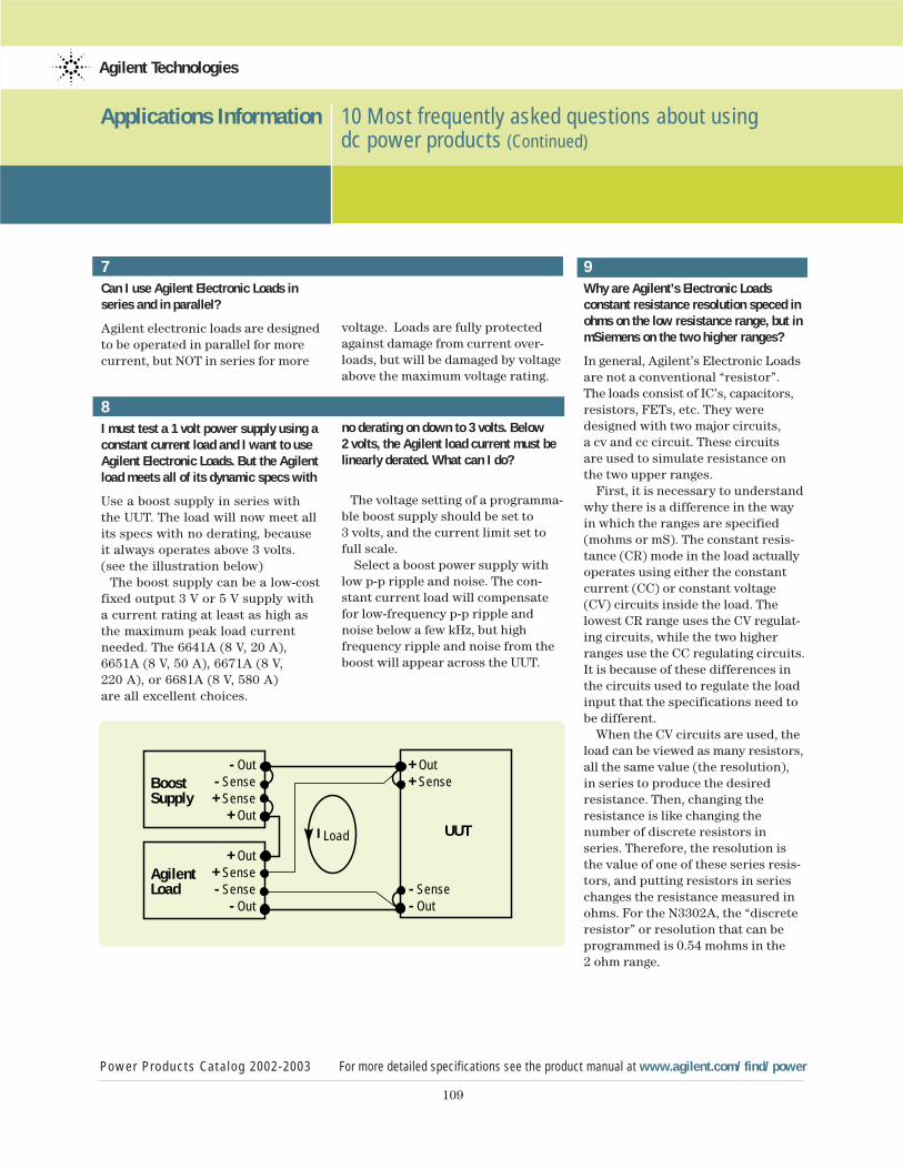
109
Applications Information 10 Most frequently asked questions about using dc power products (Continued)
Power Products Catalog 2002-2003 For more detailed specifications see the product manual at www.agilent.com/find/power
Agilent Technologies
7Can I use Agilent Electronic Loads inseries and in parallel?
Agilent electronic loads are designedto be operated in parallel for more current, but NOT in series for more
8I must test a 1 volt power supply using aconstant current load and I want to useAgilent Electronic Loads. But the Agilentload meets all of its dynamic specs with
Use a boost supply in series withthe UUT. The load will now meet allits specs with no derating, becauseit always operates above 3 volts. (see the illustration below)
The boost supply can be a low-costfixed output 3 V or 5 V supply witha current rating at least as high asthe maximum peak load currentneeded. The 6641A (8 V, 20 A),6651A (8 V, 50 A), 6671A (8 V, 220 A), or 6681A (8 V, 580 A) are all excellent choices.
voltage. Loads are fully protectedagainst damage from current over-loads, but will be damaged by voltageabove the maximum voltage rating.
no derating on down to 3 volts. Below 2 volts, the Agilent load current must belinearly derated. What can I do?
The voltage setting of a programma-ble boost supply should be set to 3 volts, and the current limit set tofull scale.
Select a boost power supply with low p-p ripple and noise. The con-stant current load will compensatefor low-frequency p-p ripple andnoise below a few kHz, but high frequency ripple and noise from theboost will appear across the UUT.
9Why are Agilent’s Electronic Loadsconstant resistance resolution speced inohms on the low resistance range, but inmSiemens on the two higher ranges?
In general, Agilent’s Electronic Loadsare not a conventional “resistor”. The loads consist of IC’s, capacitors,resistors, FETs, etc. They weredesigned with two major circuits, a cv and cc circuit. These circuits are used to simulate resistance onthe two upper ranges.
First, it is necessary to understandwhy there is a difference in the wayin which the ranges are specified(mohms or mS). The constant resis-tance (CR) mode in the load actuallyoperates using either the constantcurrent (CC) or constant voltage(CV) circuits inside the load. Thelowest CR range uses the CV regulat-ing circuits, while the two higherranges use the CC regulating circuits.It is because of these differences inthe circuits used to regulate the loadinput that the specifications need tobe different.
When the CV circuits are used, theload can be viewed as many resistors,all the same value (the resolution), in series to produce the desiredresistance. Then, changing the resistance is like changing the number of discrete resistors inseries. Therefore, the resolution isthe value of one of these series resis-tors, and putting resistors in serieschanges the resistance measured inohms. For the N3302A, the “discreteresistor” or resolution that can beprogrammed is 0.54 mohms in the 2 ohm range.
UUT
BoostSupply
- Out- Sense+ Sense
+ Out
+ Out+ Sense
I Load
AgilentLoad
+ Out+ Sense- Sense
- Out- Sense- Out
110
Applications Information 10 Most frequently asked questions about using dc power products (Continued)
Power Products Catalog 2002-2003 For more detailed specifications see the product manual at www.agilent.com/find/power
Agilent Technologies
When the CC circuits are used, theload can be viewed as many resis-tors, all the same value (the resolu-tion), in parallel to produce thedesired resistance. Then, changingthe resistance is like changing thenumber of discrete resistors in parallel. Therefore, the resolution isthe value of one of these parallelresistors, and putting resistors inparallel changes the conductancemeasured in siemens. For the60501B, the “discrete resistor” orresolution that can be programmedis 0.14 mS (=7.14 kohms).
For example, in the 2 kohm range,you can program the load input from 2 ohms to 2 kohms (0.5 S to 0.5 mS)with a resolution of 0.14 mS. Thiswould be the equivalent of startingwith about 3568 7.143 kohm resis-tors in parallel with each other, andin parallel with a 2 kohm resistor,and removing one at a time until youhad only the 2 kohm resistor left.
Note that the resolution of the conductance is constant at 0.14 mS,however, the resolution of the totalparallel resistance is not constant. It depends on how many resistorsyou have in parallel.
If you have two 7.143 kohm resis-tors in parallel and remove one, theresolution looks like 3571.5 ohms. Ifyou have 3568 7.143 kohm resistorsin parallel and remove one, the resolution looks like (7143/3567) -(7143/3568) = 0.561 mohms. But theconductance resolution is constantat 0.14 mS.
10Can Agilent power supplies be programmed from 0 to full outputvoltage using a 0 to 10 V signalsource?
Yes, many Agilent power supplies feature remote voltage programmingor analog programming capability.However, there is a potential danger in analog programming any power supply, especially a high voltage supply. If the 0 to 10 V programmingsource is a typical, non-isolated, low-cost, digital-to-analog converter(DAC), it is probably groundedthrough its digital inputs and/orthrough the computer’s internalpower supplies, which are groundedthrough the computer’s power cord.It’s easy to overlook this, and themistake can be very expensive.
If the DAC is non-isolated (or iso-lated only up to 42 V above ground)and one of the output terminals ofthe power supply is grounded, eitherdirectly or through the UUT, the out-put capacitor of the power supplycan discharge through the computer backplane, motherboard, and the I/Ocommon through the computerpower cord ground. The resultinghigh current may even last longenough to vaporize the thin groundtracks on some or all of the printedcircuit boards in the PC.
Be sure the programming source iselectrically isolated, is operated fromisolated power supplies, and is ratedfor floating voltages up to the fulloutput voltage of the programmedsupply. This is necessary so no one is hurt, and no equipment isdamaged, no matter which outputterminal of the power supply or UUT is grounded.
For additional questions andanswers visit our web site at www.agilent.com/find/answers
111
Applications Information ac Power and Load Connections
Power Products Catalog 2002-2003 For more detailed specifications see the product manual at www.agilent.com/find/power
Agilent Technologies
A modern stabilized dc power supplyis a versatile high performanceinstrument capable of delivering a constant or controlled output reliably and with little attention. But to take full advantage of the performance characteristicsdesigned into a supply, certain basicprecautions must be observed whenconnecting it for use on the lab benchor installing it in a system. Factorssuch as wire ratings, system ground-ing techniques, and the particularway that ac input, dc output, andremote error sensing connectionsare made can contribute materiallyto obtaining the stable, low noiseoutput expected by the user. Carefulattention to the following guidelinescan help to ensure the trouble freeoperation of your Agilent power supply.
ac Power Input Connections
Wire Rating
RULE 1. When connecting ac power to apower supply, always use a wire sizerated to carry at least the maximumpower supply input current.
If a long cable is involved, make anadditional check to determinewhether a still larger wire size mightbe required to retain a sufficientlylow impedance from the service out-let to the power supply input termi-nals. As a general guideline, inputcables should be of sufficient size to ensure that the voltage drop atmaximum rated power supply inputcurrent will not exceed 1% of thenominal line voltage.
Continuity
RULE 2. Maintain the continuity of theac, acc, and grounding wires from theac power outlet to the power supplyinput terminals without an accidentalinterchange.
Interchanging the ac and groundingwires may result in the power supplychassis being elevated to an acpotential equal to the input line voltage. If the chassis is groundedelsewhere, the result may be noworse than some blown fuses. But if the chassis is not grounded, theresult could be a potentially lethalshock hazard. Confirm that the chassis is grounded by the groundingwire.
Transformers
RULE 3. If an autotransformer or an isolation transformer is connectedbetween the ac power source and thepower supply input terminals, it shouldbe rated for at least 200% of the maximum rms current required by the power supply.
The transformer must have a higherrating than would be suggested by the supply’s rms input currentbecause a power supply input circuitdoes not draw current continuously.Input current peaks can cause asmaller transformer to saturate,resulting in failure of the supply tomeet its specifications at full output.
RULE 4. Be sure to connect the commonterminal of an autotransformer to theacc (and not the ac) terminals of boththe power supply and the input powerline.
If acc is not connected to the common terminal of the autotrans-former, the power supply’s input acc terminal will have a higher thannormal ac voltage connected to it,contributing to a shock hazard and,in some instances, a greater outputripple.
ac Line Regulator
RULE 5. Do not use an ac line regulatorat the input to a regulated power supplywithout first checking with the powersupply manufacturer.
Some regulators tend to increase theimpedance of the line in a resonantfashion and can cause power sup-plies to malfunction, particularly ifthey use SCR or switching regulatorsor preregulators. Moreover, since thecontrol action of many line voltageregulators is accompanied by achange in the output waveshape,their advantage in providing a constant rms input to a power supply is small. In fact these changes in waveshape are often just as disruptive in causing powersupply output changes as the origi-nal line voltage amplitude changeswould have been.
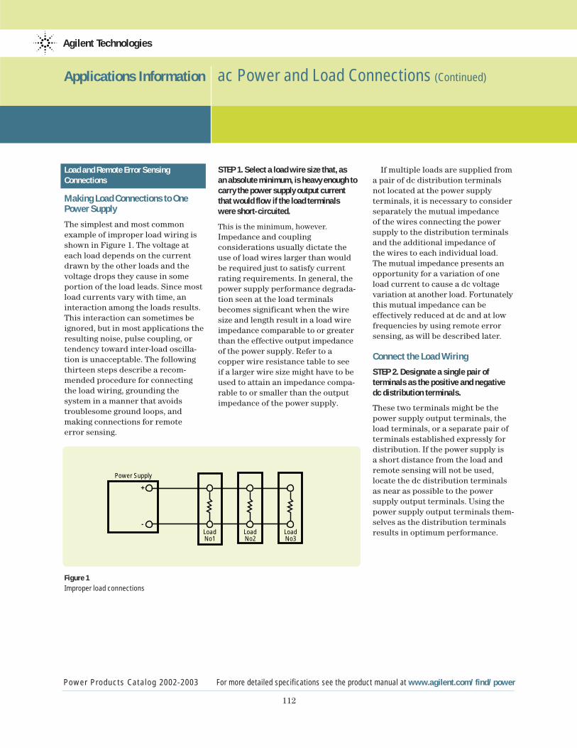
112
Applications Information ac Power and Load Connections (Continued)
Power Products Catalog 2002-2003 For more detailed specifications see the product manual at www.agilent.com/find/power
Agilent Technologies
Load and Remote Error SensingConnections
Making Load Connections to OnePower Supply
The simplest and most commonexample of improper load wiring isshown in Figure 1. The voltage ateach load depends on the currentdrawn by the other loads and thevoltage drops they cause in someportion of the load leads. Since mostload currents vary with time, aninteraction among the loads results.This interaction can sometimes beignored, but in most applications theresulting noise, pulse coupling, ortendency toward inter-load oscilla-tion is unacceptable. The followingthirteen steps describe a recom-mended procedure for connectingthe load wiring, grounding thesystem in a manner that avoids troublesome ground loops, and making connections for remote error sensing.
Figure 1Improper load connections
STEP 1. Select a load wire size that, as an absolute minimum, is heavy enough tocarry the power supply output currentthat would flow if the load terminals were short-circuited.
This is the minimum, however.Impedance and couplingconsiderations usually dictate theuse of load wires larger than wouldbe required just to satisfy currentrating requirements. In general, thepower supply performance degrada-tion seen at the load terminalsbecomes significant when the wiresize and length result in a load wireimpedance comparable to or greaterthan the effective output impedanceof the power supply. Refer to a copper wire resistance table to see if a larger wire size might have to beused to attain an impedance compa-rable to or smaller than the outputimpedance of the power supply.
If multiple loads are supplied froma pair of dc distribution terminalsnot located at the power supply terminals, it is necessary to considerseparately the mutual impedance of the wires connecting the powersupply to the distribution terminalsand the additional impedance of the wires to each individual load. The mutual impedance presents anopportunity for a variation of oneload current to cause a dc voltagevariation at another load. Fortunatelythis mutual impedance can be effectively reduced at dc and at lowfrequencies by using remote errorsensing, as will be described later.
Connect the Load Wiring
STEP 2. Designate a single pair of terminals as the positive and negativedc distribution terminals.
These two terminals might be thepower supply output terminals, theload terminals, or a separate pair ofterminals established expressly fordistribution. If the power supply isa short distance from the load andremote sensing will not be used,locate the dc distribution terminalsas near as possible to the power supply output terminals. Using thepower supply output terminals them-selves as the distribution terminalsresults in optimum performance. Load
No1
Power Supply
+
-
LoadNo2
LoadNo3
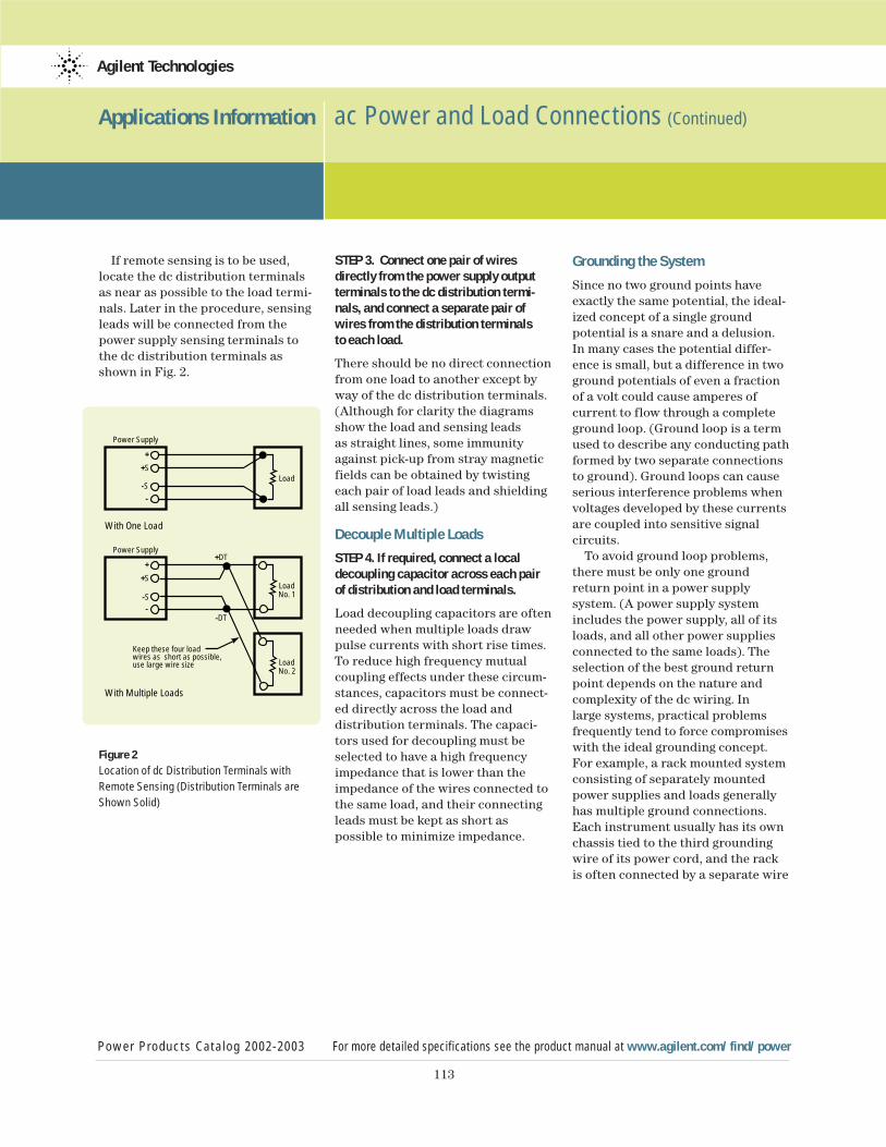
113
Applications Information ac Power and Load Connections (Continued)
Power Products Catalog 2002-2003 For more detailed specifications see the product manual at www.agilent.com/find/power
Agilent Technologies
If remote sensing is to be used,locate the dc distribution terminalsas near as possible to the load termi-nals. Later in the procedure, sensingleads will be connected from thepower supply sensing terminals tothe dc distribution terminals asshown in Fig. 2.
Figure 2Location of dc Distribution Terminals with
Remote Sensing (Distribution Terminals are
Shown Solid)
STEP 3. Connect one pair of wiresdirectly from the power supply outputterminals to the dc distribution termi-nals, and connect a separate pair ofwires from the distribution terminals to each load.
There should be no direct connectionfrom one load to another except byway of the dc distribution terminals.(Although for clarity the diagramsshow the load and sensing leads as straight lines, some immunityagainst pick-up from stray magneticfields can be obtained by twistingeach pair of load leads and shieldingall sensing leads.)
Decouple Multiple Loads
STEP 4. If required, connect a localdecoupling capacitor across each pairof distribution and load terminals.
Load decoupling capacitors are oftenneeded when multiple loads drawpulse currents with short rise times.To reduce high frequency mutualcoupling effects under these circum-stances, capacitors must be connect-ed directly across the load anddistribution terminals. The capaci-tors used for decoupling must beselected to have a high frequencyimpedance that is lower than theimpedance of the wires connected tothe same load, and their connectingleads must be kept as short aspossible to minimize impedance.
Grounding the System
Since no two ground points haveexactly the same potential, the ideal-ized concept of a single groundpotential is a snare and a delusion.In many cases the potential differ-ence is small, but a difference in twoground potentials of even a fractionof a volt could cause amperes of current to flow through a completeground loop. (Ground loop is a termused to describe any conducting pathformed by two separate connectionsto ground). Ground loops can causeserious interference problems whenvoltages developed by these currentsare coupled into sensitive signal circuits.
To avoid ground loop problems,there must be only one groundreturn point in a power supply system. (A power supply systemincludes the power supply, all of itsloads, and all other power suppliesconnected to the same loads). Theselection of the best ground returnpoint depends on the nature andcomplexity of the dc wiring. In large systems, practical problemsfrequently tend to force compromiseswith the ideal grounding concept.For example, a rack mounted systemconsisting of separately mountedpower supplies and loads generallyhas multiple ground connections.Each instrument usually has its ownchassis tied to the third groundingwire of its power cord, and the rackis often connected by a separate wire
Power Supply
+S
+DT
-DT
LoadNo. 1
Keep these four loadwires as short as possible,use large wire size Load
No. 2
-S
+
-
Power Supply
+SLoad
-S
+
-
With One Load
With Multiple Loads
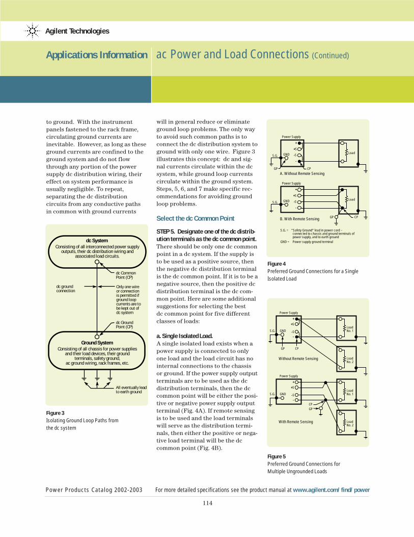
114
Applications Information ac Power and Load Connections (Continued)
Power Products Catalog 2002-2003 For more detailed specifications see the product manual at www.agilent.com/find/power
Agilent Technologies
to ground. With the instrument panels fastened to the rack frame,circulating ground currents areinevitable. However, as long as theseground currents are confined to theground system and do not flowthrough any portion of the powersupply dc distribution wiring, theireffect on system performance is usually negligible. To repeat,separating the dc distribution circuits from any conductive paths in common with ground currents
Figure 3 Isolating Ground Loop Paths from
the dc system
will in general reduce or eliminate ground loop problems. The only wayto avoid such common paths is toconnect the dc distribution system toground with only one wire. Figure 3illustrates this concept: dc and sig-nal currents circulate within the dcsystem, while ground loop currentscirculate within the ground system.Steps, 5, 6, and 7 make specific rec-ommendations for avoiding groundloop problems.
Select the dc Common Point
STEP 5. Designate one of the dc distrib-ution terminals as the dc common point.There should be only one dc commonpoint in a dc system. If the supply isto be used as a positive source, thenthe negative dc distribution terminalis the dc common point. If it is to be anegative source, then the positive dcdistribution terminal is the dc com-mon point. Here are some additionalsuggestions for selecting the best dc common point for five differentclasses of loads:
a. Single Isolated Load. A single isolated load exists when apower supply is connected to only one load and the load circuit has nointernal connections to the chassis or ground. If the power supply outputterminals are to be used as the dc distribution terminals, then the dccommon point will be either the posi-tive or negative power supply outputterminal (Fig. 4A). If remote sensingis to be used and the load terminalswill serve as the distribution termi-nals, then either the positive or nega-tive load terminal will be the dccommon point (Fig. 4B).
Figure 4 Preferred Ground Connections for a Single
Isolated Load
Figure 5Preferred Ground Connections for
Multiple Ungrounded Loads
dc System
Ground System
dc Ground Point (CP)
Consisting of all interconnected power supplyoutputs, their dc distribution wiring and
associated load circuits.
Consisting of all chassis for power supplies and their load devices, their ground
terminals, safety ground,ac ground wiring, rack frames, etc.
dc Common Point (CP)
dc ground connection
All eventually leadto earth ground
Only one wire or connectionis permitted if ground loop currents are to be kept out of dc system
Power Supply
+SLoadGNDS.G.
GP CPA. Without Remote Sensing
S.G. = ”Safety Ground“ lead in power cord –connected to chassis and ground terminals of power supply, and to earth ground
GND = Power supply ground terminal
-S
+
-
Power Supply
+SLoadGNDS.G.
GP CPB. With Remote Sensing
-S
+
-
Without Remote Sensing
Power Supply
+SLoadNo. 1
LoadNo. 2
-S
+
-
With Remote Sensing
CPGP
S.G. GND
Power Supply
+SLoadNo. 1
LoadNo. 2
-S
+
-
GP CP
S.G. GND
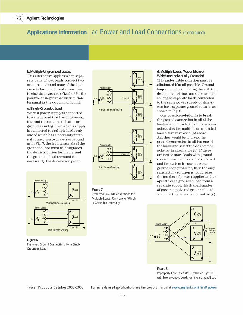
115
Applications Information ac Power and Load Connections (Continued)
Power Products Catalog 2002-2003 For more detailed specifications see the product manual at www.agilent.com/find/power
Agilent Technologies
b. Multiple Ungrounded Loads.This alternative applies when sepa-rate pairs of load leads connect twoor more loads and none of the loadcircuits has an internal connectionto chassis or ground (Fig. 5). Use thepositive or negative dc distributionterminal as the dc common point.
c. Single Grounded Load. When a power supply is connected to a single load that has a necessaryinternal connection to chassis orground as in Fig. 6, or when a supplyis connected to multiple loads onlyone of which has a necessary inter-nal connection to chassis or groundas in Fig. 7, the load terminals of thegrounded load must be designatedthe dc distribution terminals, andthe grounded load terminal is necessarily the dc common point.
Figure 6 Preferred Ground Connections for a Single
Grounded Load
Figure 7 Preferred Ground Connections for
Multiple Loads, Only One of Which
is Grounded Internally
d. Multiple Loads, Two or More of Which are Individually Grounded.This undesirable situation must beeliminated if at all possible. Groundloop currents circulating through thedc and load wiring cannot be avoidedso long as separate loads connectedto the same power supply or dc sys-tem have separate ground returns asshown in Fig. 8.
One possible solution is to breakthe ground connection in all of theloads and then select the dc commonpoint using the multiple ungroundedload alternative as in (b) above.Another would be to break theground connection in all but one ofthe loads and select the dc commonpoint as in alternative (c). If thereare two or more loads with groundconnections that cannot be removedand the system is susceptible toground loop problems, then the onlysatisfactory solution is to increasethe number of power supplies and tooperate each grounded load from aseparate supply. Each combinationof power supply and grounded loadwould be treated as in alternative (c).
Figure 8Improperly Connected dc Distribution System
with Two Grounded Loads forming a Ground Loop
Power Supply
+SLoadGNDS.G.
CP and GPWithout Remote Sensing
-S
+
-
Power Supply
+SLoadGNDS.G.
CP and GPWith Remote Sensing
-S
+
-
With Remote Sensing
Power Supply
+S LoadNo 2
LoadNo 1
LoadNo 3
GNDS.G. CP and GP
Without Remote Sensing
-S
+
-
Power Supply
+S LoadNo 2
LoadNo 1
LoadNo 3
GNDS.G.CP and GP
-S
+
-
Power Supply
+S LoadNo 2
LoadNo 1
LoadNo 3
GNDS.G.
GroundVoltageSource
-S
+
-
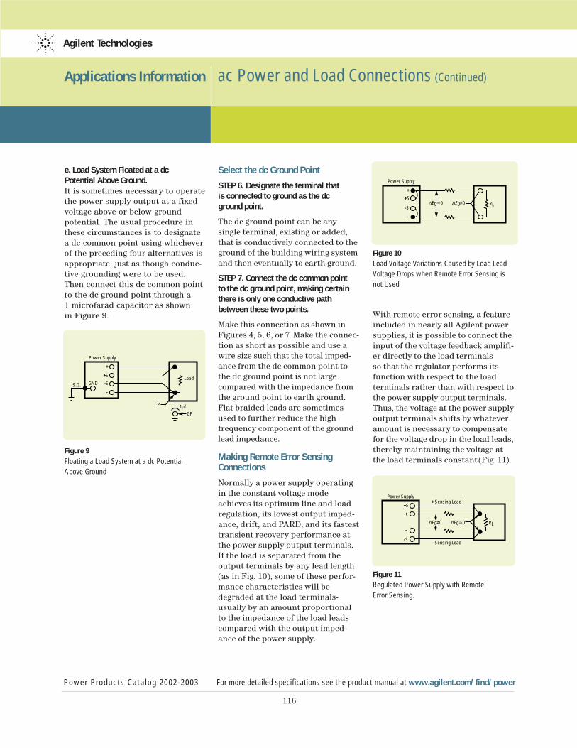
116
Applications Information ac Power and Load Connections (Continued)
Power Products Catalog 2002-2003 For more detailed specifications see the product manual at www.agilent.com/find/power
Agilent Technologies
e. Load System Floated at a dc Potential Above Ground.It is sometimes necessary to operatethe power supply output at a fixedvoltage above or below ground potential. The usual procedure inthese circumstances is to designate a dc common point using whicheverof the preceding four alternatives isappropriate, just as though conduc-tive grounding were to be used.Then connect this dc common point to the dc ground point through a 1 microfarad capacitor as shown in Figure 9.
Figure 9 Floating a Load System at a dc Potential
Above Ground
Select the dc Ground Point
STEP 6. Designate the terminal that is connected to ground as the dc ground point.
The dc ground point can be any single terminal, existing or added,that is conductively connected to theground of the building wiring systemand then eventually to earth ground.
STEP 7. Connect the dc common point to the dc ground point, making certainthere is only one conductive pathbetween these two points.
Make this connection as shown inFigures 4, 5, 6, or 7. Make the connec-tion as short as possible and use awire size such that the total imped-ance from the dc common point tothe dc ground point is not large compared with the impedance fromthe ground point to earth ground.Flat braided leads are sometimesused to further reduce the high frequency component of the groundlead impedance.
Making Remote Error SensingConnections
Normally a power supply operating in the constant voltage modeachieves its optimum line and loadregulation, its lowest output imped-ance, drift, and PARD, and its fastesttransient recovery performance atthe power supply output terminals.If the load is separated from the output terminals by any lead length(as in Fig. 10), some of these perfor-mance characteristics will bedegraded at the load terminals-usually by an amount proportionalto the impedance of the load leadscompared with the output imped-ance of the power supply.
Figure 10 Load Voltage Variations Caused by Load Lead
Voltage Drops when Remote Error Sensing is
not Used
With remote error sensing, a featureincluded in nearly all Agilent powersupplies, it is possible to connect theinput of the voltage feedback amplifi-er directly to the load terminals so that the regulator performs itsfunction with respect to the load terminals rather than with respect tothe power supply output terminals.Thus, the voltage at the power supplyoutput terminals shifts by whateveramount is necessary to compensatefor the voltage drop in the load leads,thereby maintaining the voltage atthe load terminals constant (Fig. 11).
Figure 11Regulated Power Supply with Remote
Error Sensing.
Power Supply
+S LoadGNDS.G.
CP
GP1µf
-S
+
-
Power Supply
+SRL
-S∆E0≠0
+
-
Power Supply+ Sensing Lead
- Sensing Lead
+
RL-
∆E0≠0 ∆E0.0
+S
-S
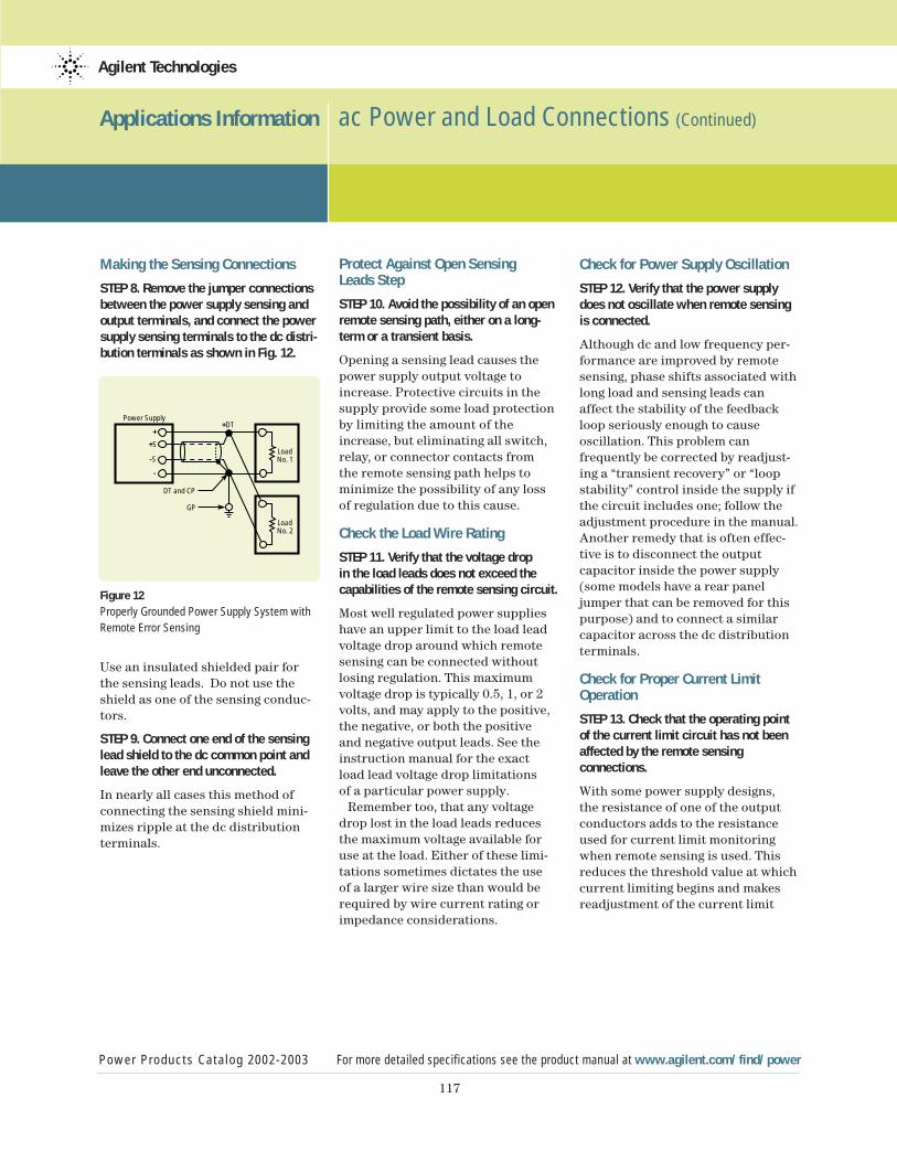
117
Applications Information ac Power and Load Connections (Continued)
Power Products Catalog 2002-2003 For more detailed specifications see the product manual at www.agilent.com/find/power
Agilent Technologies
Making the Sensing Connections
STEP 8. Remove the jumper connectionsbetween the power supply sensing andoutput terminals, and connect the powersupply sensing terminals to the dc distri-bution terminals as shown in Fig. 12.
Figure 12 Properly Grounded Power Supply System with
Remote Error Sensing
Use an insulated shielded pair forthe sensing leads. Do not use theshield as one of the sensing conduc-tors.
STEP 9. Connect one end of the sensinglead shield to the dc common point andleave the other end unconnected.
In nearly all cases this method ofconnecting the sensing shield mini-mizes ripple at the dc distributionterminals.
Protect Against Open Sensing Leads Step
STEP 10. Avoid the possibility of an openremote sensing path, either on a long-term or a transient basis.
Opening a sensing lead causes thepower supply output voltage toincrease. Protective circuits in thesupply provide some load protectionby limiting the amount of theincrease, but eliminating all switch,relay, or connector contacts from the remote sensing path helps tominimize the possibility of any lossof regulation due to this cause.
Check the Load Wire Rating
STEP 11. Verify that the voltage drop in the load leads does not exceed thecapabilities of the remote sensing circuit.
Most well regulated power supplieshave an upper limit to the load leadvoltage drop around which remotesensing can be connected withoutlosing regulation. This maximumvoltage drop is typically 0.5, 1, or 2volts, and may apply to the positive,the negative, or both the positive and negative output leads. See theinstruction manual for the exact load lead voltage drop limitations of a particular power supply.
Remember too, that any voltagedrop lost in the load leads reducesthe maximum voltage available foruse at the load. Either of these limi-tations sometimes dictates the use of a larger wire size than would berequired by wire current rating orimpedance considerations.
Check for Power Supply Oscillation
STEP 12. Verify that the power supplydoes not oscillate when remote sensingis connected.
Although dc and low frequency per-formance are improved by remotesensing, phase shifts associated withlong load and sensing leads canaffect the stability of the feedbackloop seriously enough to cause oscillation. This problem canfrequently be corrected by readjust-ing a “transient recovery” or “loopstability” control inside the supply ifthe circuit includes one; follow theadjustment procedure in the manual.Another remedy that is often effec-tive is to disconnect the outputcapacitor inside the power supply(some models have a rear paneljumper that can be removed for thispurpose) and to connect a similarcapacitor across the dc distributionterminals.
Check for Proper Current LimitOperation
STEP 13. Check that the operating pointof the current limit circuit has not beenaffected by the remote sensingconnections.
With some power supply designs, the resistance of one of the outputconductors adds to the resistanceused for current limit monitoringwhen remote sensing is used. Thisreduces the threshold value at whichcurrent limiting begins and makesreadjustment of the current limit
Power Supply
+S
+DT
LoadNo. 1
DT and CP
GP
LoadNo. 2
-S
+
-
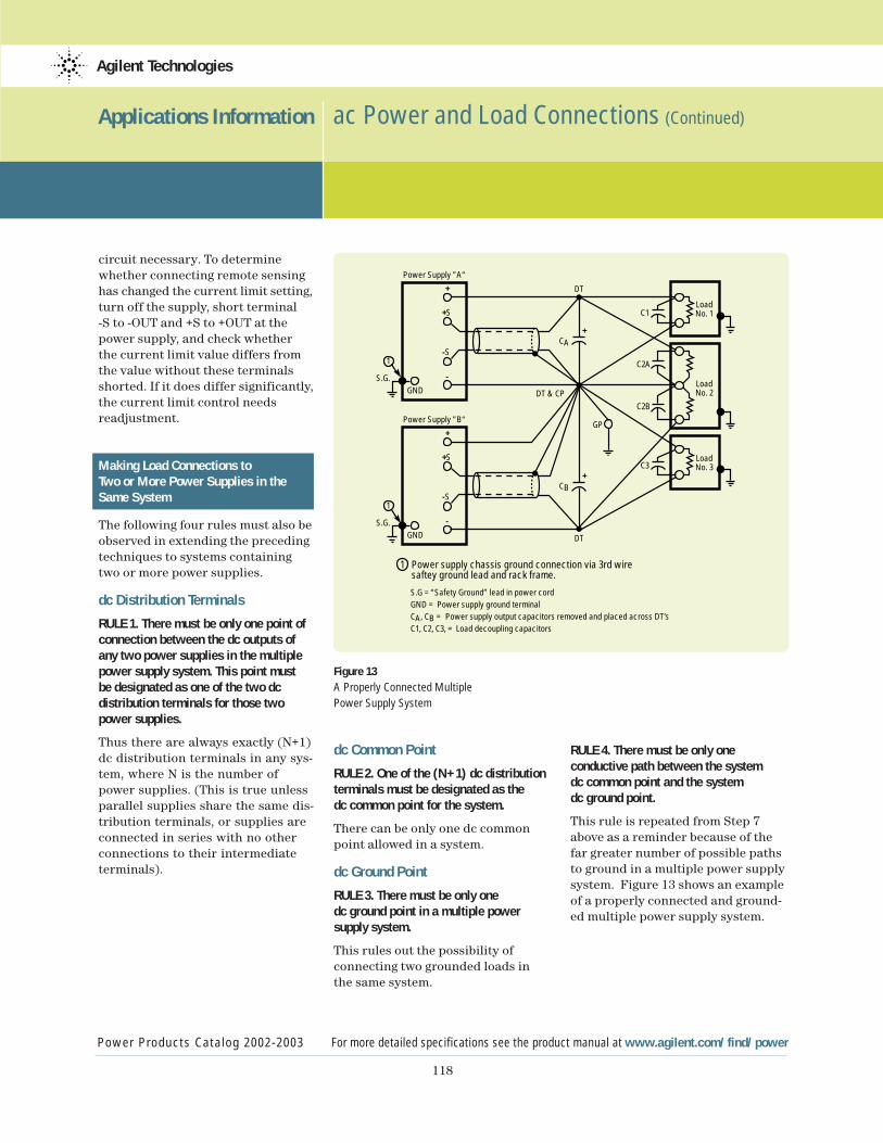
118
Applications Information ac Power and Load Connections (Continued)
Power Products Catalog 2002-2003 For more detailed specifications see the product manual at www.agilent.com/find/power
Agilent Technologies
circuit necessary. To determinewhether connecting remote sensinghas changed the current limit setting,turn off the supply, short terminal -S to -OUT and +S to +OUT at thepower supply, and check whether the current limit value differs fromthe value without these terminalsshorted. If it does differ significantly,the current limit control needs readjustment.
Making Load Connections to Two or More Power Supplies in the Same System
The following four rules must also beobserved in extending the precedingtechniques to systems containingtwo or more power supplies.
dc Distribution Terminals
RULE 1. There must be only one point ofconnection between the dc outputs ofany two power supplies in the multiplepower supply system. This point must be designated as one of the two dc distribution terminals for those twopower supplies.
Thus there are always exactly (N+1)dc distribution terminals in any sys-tem, where N is the number ofpower supplies. (This is true unlessparallel supplies share the same dis-tribution terminals, or supplies areconnected in series with no otherconnections to their intermediateterminals).
Figure 13 A Properly Connected Multiple
Power Supply System
dc Common Point
RULE 2. One of the (N+1) dc distributionterminals must be designated as the dc common point for the system.
There can be only one dc commonpoint allowed in a system.
dc Ground Point
RULE 3. There must be only one dc ground point in a multiple power supply system.
This rules out the possibility of connecting two grounded loads inthe same system.
RULE 4. There must be only one conductive path between the system dc common point and the system dc ground point.
This rule is repeated from Step 7above as a reminder because of thefar greater number of possible pathsto ground in a multiple power supplysystem. Figure 13 shows an exampleof a properly connected and ground-ed multiple power supply system.
LoadNo. 1
LoadNo. 3
LoadNo. 2
C1
C2A
CA
C2B
C3
GP
+
CB+
S.G.
Power Supply ”A“
+S
1
+
-S
GND
-
S.G.
Power Supply ”B“
+S
1
+
-S
GND
-
DT
DT
DT & CP
S.G = “Safety Ground” lead in power cordGND = Power supply ground terminalCA, CB = Power supply output capacitors removed and placed across DT’sC1, C2, C3, = Load decoupling capacitors
1 Power supply chassis ground connection via 3rd wire saftey ground lead and rack frame.

119
Applications Information Agilent Application Notes
Power Products Catalog 2002-2003 For more detailed specifications see the product manual at www.agilent.com/find/power
Agilent Technologies
These documents and other helpful applications information are available both on the AgilentTechnologies Power Products web-site (www.agilent.com/find/power)and through any Agilent Sales Office.
AN 372-1Power Supply TestingAn electronic load offers a broadrange of operating modes, providingversatile loading configurationsneeded for characterizing and verifying dc power supply designspecifications.
p/n 5952-4190
AN 372-2Battery Testing An electronic load can be used todischarge batteries of variouschemistries to determine actualcapacity, capacity retention, andimpedance.
p/n 5952-4191
AN 1246Pulsed Characterization of PowerSemiconductors Using Electronic LoadsAn electronic load eliminates theself-heating problems associatedwith measuring the on-state voltagedrop and transconductance (or cur-rent gain) of power semiconductors.
p/n 5091-7636E
AN 1293 Sequential Shunt RegulationThis sequential shunt regulation is widely used for regulating thesatellite bus voltage, powered bysolar arrays. The E4350B/E4351Bsolar array simulators (SAS) areideal for this type of application.
p/n 5965-7329E
AN 1310Considerations when selecting a system power supply for mobile communication device testingPulsed battery drain currents, regulated charge currents, andremote DUT (Device Under Test) fixtures, dictate the need for specialized power sourcing, loading,and measurement capabilities fortesting mobile communicationsdevices. Many of these capabilitiesare not available in general-purposesystem power supplies.
This guide will assist the test system designer in selecting a system power supply by properly evaluating test system and powersupply needs that are unique to theapplication and not immediatelyobvious.
p/n 5968-2424E
AN 1396 Optimizing BluetoothTM Device BatteryDrain Measurements in ManufacturingBattery operating time is a criticalparameter for portable devices.This application note describes the procedures that can be used in manufacturing test to ensure a minimum operating time forportable BluetoothTM devices.
p/n 5988-6064EN

120
Applications Information Agilent Application Notes (Continued)
Power Products Catalog 2002-2003 For more detailed specifications see the product manual at www.agilent.com/find/power
Agilent Technologies
Product Note Increasing dc Power Supply Test SystemThroughput with Agilent TechnologiesN3300A dc Electronic LoadsBy using fast electronic loads, and avariety of programming techniques,production throughput can begreatly enhanced.
p/n 5980-0233E
Product Note Agilent dc Power Supplies for BaseStation Testing By choosing the correct power supply for the application, andusing the features appropriately,the manufacturer of base stationsand base station components canreduce manufacturing cost, andproduce a more robust product.
p/n 5988-2386EN
Product Note Testing Uninterruptible Power Suppliesusing Agilent 6800 Series ac powersource/analyzersAgilent ac sources can be used tohelp test uninterruptible powersupplies in many different environ-ments, including research anddevelopment, manufacturing, andincoming inspection. Ensuring thatthe UPS is designed and operatingproperly is essential to guaranteethat the UPS will satisfactorily protect sensitive equipment againstac mains voltage abnormalities.
p/n 5967-6056E
Product Note Zero Volt Electronic LoadIncreasing demand for lower volt-age power supplies is pressuringtest system designers to identifyelectronic load test equipmentdesigned to adequately perform atthese lower voltages. Read how toconfigure Agilent dc ElectronicLoads, with option J04, to performaccurate dynamic loading completelydown to zero volts.
p/n 5968-6360E
Product NoteMaking Fuel Cell ac Impedance measurements utilizing Agilent N3300ASeries Electronic LoadsMaking ac impedance measurementson fuel cells can help identify prob-lems with the fuel cell componentsand help identify deviations in thefuel cell assembly process. Thisproduct note explains how an electronic load can be used to make Electrochemical ImpedanceSpectroscopy measurements.
p/n 5988-5358EN
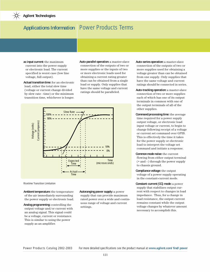
121
Applications Information Power Products Terms
Power Products Catalog 2002-2003 For more detailed specifications see the product manual at www.agilent.com/find/power
Agilent Technologies
ac input current: the maximum current into the power supplyor electronic load. The current specified is worst case (low line voltage, full output).
Actual transition time: for an electronicload, either the total slew time (voltage or current change dividedby slew rate - time) or the minimumtransition time, whichever is longer.
Ambient temperature: the temperatureof the air immediately surroundingthe power supply or electronic load.
Analog programming: controlling theoutput voltage and/or current withan analog signal. This signal couldbe a voltage, current or resistance.This is similar to using the power supply as an amplifier.
Auto-parallel operation: a master-slaveconnection of the outputs of two ormore supplies or the inputs of twoor more electronic loads used forobtaining a current rating greaterthan can be obtained from a singleload or supply. Only supplies thathave the same voltage and currentratings should be paralleled.
Autoranging power supply: a powersupply that can provide maximumrated power over a wide and contin-uous range of voltage and currentsettings.
Auto-series operation: a master-slaveconnection of the outputs of two ormore supplies used for obtaining avoltage greater than can be obtainedfrom one supply. Only supplies thathave the same voltage and currentratings should be connected in series.
Auto-tracking operation: a master-slaveconnection of two or more supplieseach of which has one of its outputterminals in common with one ofthe output terminals of all of the other supplies.
Command processing time: the averagetime required for a power supplyoutput voltage, or electronic loadinput voltage or current, to begin tochange following receipt of a voltageor current set command over GPIB.This is effectively the time it takesfor the power supply or electronicload to interpret the voltage setcommand and initiate a response.
Common mode noise: the current flowing from either output terminal(+ and –) through the power supplyto chassis ground.
Compliance voltage: the output voltage of a power supply operatingin the constant-current mode.
Constant-current (CC) mode: a powersupply that stabilizes output cur-rent with respect to changes in loadimpedance. Thus, for a change inload resistance, the output currentremains constant while the outputvoltage changes by whatever amountnecessary to accomplish this.
Risetime Transition Limitation
10%0%
100%90%
Slew Rate
ExpectedTime
ActualTime
Time(microseconds)
Volta
ge (v
olts
)or
Cur
rent
(am
pere
s)
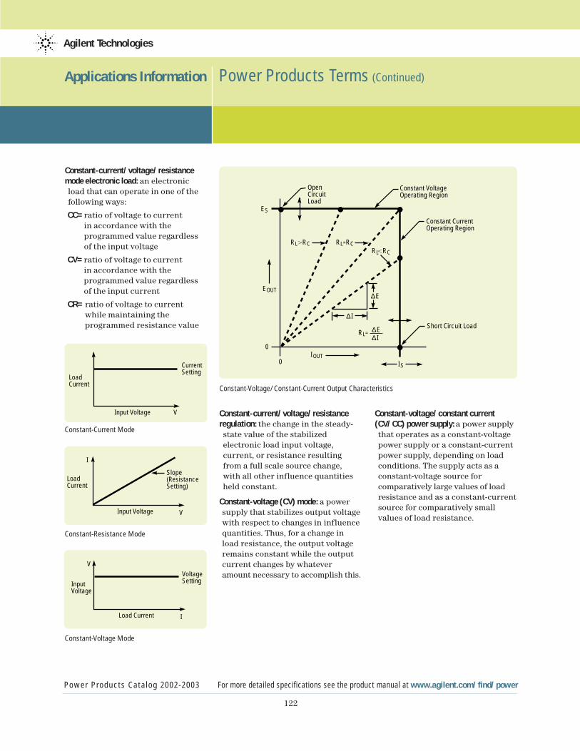
122
Applications Information Power Products Terms (Continued)
Power Products Catalog 2002-2003 For more detailed specifications see the product manual at www.agilent.com/find/power
Agilent Technologies
Constant-current/voltage/resistancemode electronic load: an electronic load that can operate in one of the following ways:
CC=ratio of voltage to current in accordance with theprogrammed value regardlessof the input voltage
CV=ratio of voltage to current in accordance with theprogrammed value regardlessof the input current
CR= ratio of voltage to current while maintaining theprogrammed resistance value
Constant-Current Mode
Constant-Resistance Mode
Constant-Voltage Mode
Constant-current/voltage/resistanceregulation: the change in the steady-state value of the stabilized electronic load input voltage, current, or resistance resulting from a full scale source change, with all other influence quantities held constant.
Constant-voltage (CV) mode: a powersupply that stabilizes output voltagewith respect to changes in influencequantities. Thus, for a change inload resistance, the output voltageremains constant while the outputcurrent changes by whateveramount necessary to accomplish this.
Constant-voltage/constant current(CV/CC) power supply: a power supply that operates as a constant-voltage power supply or a constant-current power supply, depending on loadconditions. The supply acts as a constant-voltage source for comparatively large values of load resistance and as a constant-currentsource for comparatively small values of load resistance.
Input Voltage
LoadCurrent
Slope(ResistanceSetting)
V
I
Input Voltage
LoadCurrent
CurrentSetting
V
Load Current
InputVoltage
VoltageSetting
V
I
Constant-Voltage/Constant-Current Output Characteristics
ES
IS
0
0IOUT
RL.RC.
∆I
∆E∆I
∆EEOUT
OpenCircuitLoad
Constant VoltageOperating Region
Constant CurrentOperating Region
Short Circuit Load
RL=RC
RL=
RL RC

123
Applications Information Power Products Terms (Continued)
Power Products Catalog 2002-2003 For more detailed specifications see the product manual at www.agilent.com/find/power
Agilent Technologies
Constant-voltage/current limiting(CV/CL) power supply: a power supplysimilar to a constant-voltage/con-stant-current supply except that at comparatively small values of load resistance, its output current is limited instead of being stabilized.
Crest factor: the ratio of the zero-to-peak value to the rms value of awaveform. This term is often used to specify the maximum peak amplitude that an ac power supplycan source (relative to its maximumrms rating) without distortion.
Crowbar: see overvoltage protection.
Current limiting: the action, underoverload or short-circuit conditions,of limiting the output current of aconstant-voltage supply to somepredetermined maximum value(fixed or adjustable) and automati-cally restoring the output voltage toits normal value when the overloador short circuit is removed. Thereare three types of current limiting:
•by constant-voltage/constant-current crossover
•by decreasing the output voltage as the current increases
•by decreasing both voltage and current as the load resistancedecreases.
DFI: a TTL compatible output signalthat can be used as an alarm andautomatically initiates an action formultiple power supply or electronicload shutdown. The DFI signal iscommonly connected to RI of thenext supply. (See RI)
Downprogramming: the ability of apower supply to discharge its outputcapacitors independently of load.The use of an active down program-ming device can reduce the fall timeof the output voltage.
Drift: the maximum change of a power supply output or load input voltage or current during an 8-hour period following a 30-minutewarmup, with all influence and control quantities maintained constant during the warm-up timeand the period of drift measurement.Drift includes both periodic andrandom deviations over the band-width from zero frequency (dc) to a specified upper frequency limit.
Efficiency: expressed in percent, efficiency is the total output powerof the supply divided by the activeinput power. Unless otherwise specified, Agilent measures efficiency at maximum rated output power and at worst case conditions of the ac line voltage.
Electromagnetic interference (EMI):any type of electromagnetic energythat could degrade the performanceof electrical equipment. The EMIgenerated by a power supply can be propagated either by conduction(via the input and output leads) or bt radiation from the units’ case.The terms “noise” and “radio-frequency interference” (RFI) aresometimes used in the same context.
Electronic Load: an active devicewhich absorbs power. Loads areused for the testing of the powerproducing products.
Foldback: immediate shutdown of the power supply output when acrossover between constant voltageand constant current mode occurs.Both the voltage and current levelsare reduced (folded back).
Harmonics: the occurrence of thistype of distortion is based upon the mathematical principle that allperiodic waveforms are made up ofa series of sine waves. As a result,harmonic distortion is produced at frequencies that are integermultiples of the fundamental ordesired signal frequency. Whenviewed in the frequency domain,harmonics have an amplitude (oftenexpressed in db), frequency, andphase characteristic relative to thefundamental.
Isolation: the maximum voltage(including output voltage) eitheroutput terminal may be floated from earth ground.
Load cross regulation: the affect on oneoutput of a multiple output powersupply when another output is programmed from zero to full ratedcurrent.
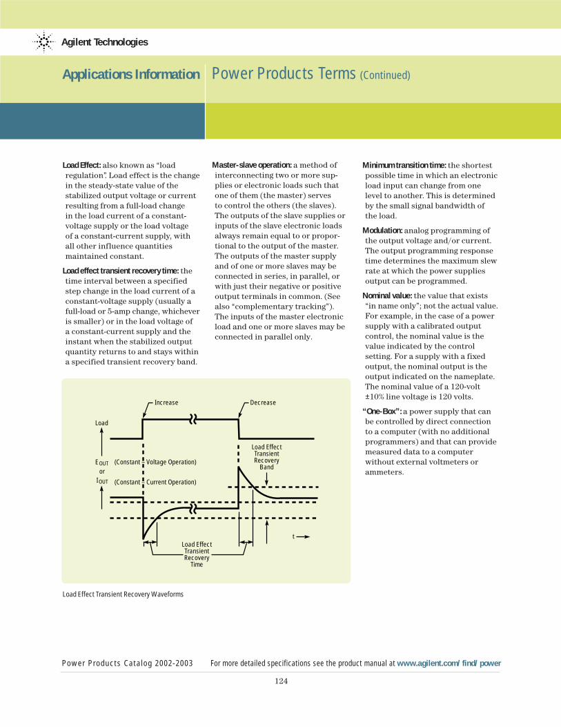
124
Applications Information Power Products Terms (Continued)
Power Products Catalog 2002-2003 For more detailed specifications see the product manual at www.agilent.com/find/power
Agilent Technologies
Load Effect: also known as “load regulation”. Load effect is the changein the steady-state value of the stabilized output voltage or currentresulting from a full-load change in the load current of a constant-voltage supply or the load voltage of a constant-current supply, withall other influence quantities maintained constant.
Load effect transient recovery time: thetime interval between a specifiedstep change in the load current of aconstant-voltage supply (usually afull-load or 5-amp change, whicheveris smaller) or in the load voltage of a constant-current supply and theinstant when the stabilized outputquantity returns to and stays withina specified transient recovery band.
Load Effect Transient Recovery Waveforms
Master-slave operation: a method ofinterconnecting two or more sup-plies or electronic loads such thatone of them (the master) serves to control the others (the slaves).The outputs of the slave supplies orinputs of the slave electronic loadsalways remain equal to or propor-tional to the output of the master.The outputs of the master supplyand of one or more slaves may beconnected in series, in parallel, orwith just their negative or positiveoutput terminals in common. (Seealso “complementary tracking”).The inputs of the master electronicload and one or more slaves may beconnected in parallel only.
Minimum transition time: the shortestpossible time in which an electronicload input can change from one level to another. This is determinedby the small signal bandwidth of the load.
Modulation: analog programming ofthe output voltage and/or current.The output programming responsetime determines the maximum slewrate at which the power suppliesoutput can be programmed.
Nominal value: the value that exists“in name only”; not the actual value.For example, in the case of a powersupply with a calibrated output control, the nominal value is thevalue indicated by the control setting. For a supply with a fixedoutput, the nominal output is theoutput indicated on the nameplate.The nominal value of a 120-volt±10% line voltage is 120 volts.
“One-Box”: a power supply that canbe controlled by direct connectionto a computer (with no additionalprogrammers) and that can providemeasured data to a computer without external voltmeters orammeters.
(Constant – Voltage Operation)
Load
Increase Decrease
Load EffectTransientRecovery
Band
Load EffectTransientRecovery
Time
EOUT
t
IOUT
or
(Constant – Current Operation)
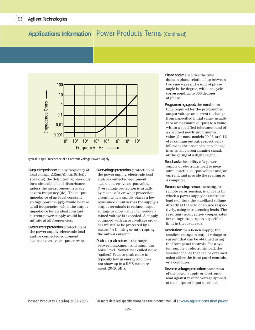
125
Applications Information Power Products Terms (Continued)
Power Products Catalog 2002-2003 For more detailed specifications see the product manual at www.agilent.com/find/power
Agilent Technologies
Output Impedance: at any frequency ofload change, ∆Eout/∆Iout. Strictlyspeaking, the definition applies onlyfor a sinusoidal load disturbance,unless the measurement is made at zero frequency (dc). The outputimpedance of an ideal constant voltage power supply would be zeroat all frequencies, while the outputimpedance for an ideal constantcurrent power supply would be infinite at all frequencies.
Overcurrent protection: protection ofthe power supply, electronic loadand/or connected equipmentagainst excessive output current.
Overvoltage protection: protection ofthe power supply, electronic loadand/or connected equipmentagainst excessive output voltage.Overvoltage protection is usuallyby means of a crowbar protectioncircuit, which rapidly places a lowresistance shunt across the supply’soutput terminals to reduce outputvoltage to a low value if a predeter-mined voltage is exceeded. A supplyequipped with an overvoltage crow-bar must also be protected by ameans for limiting or interruptingthe output current.
Peak-to-peak noise: is the rangebetween maximum and minimumnoise level. Sometimes called noise“spikes.” Peak-to-peak noise is typically low in energy and does not show up in a RMS measure-ment, 20-20 Mhz.
Phase angle: specifies the timedomain phase relationship betweentwo sine waves. The unit of phaseangle is the degree, with one cyclecorresponding to 360 degrees of phase.
Programming speed: the maximumtime required for the programmedoutput voltage or current to changefrom a specified initial value (usuallyzero or maximum output) to a valuewithin a specified tolerance band ofa specified newly programmedvalue (for most models 99.9% or 0.1%of maximum output, respectively)following the onset of a step changein an analog programming signal, or the gating of a digital signal.
Readback: the ability of a power supply or electronic load to mea-sure its actual output voltage and/orcurrent, and provide the reading to a computer.
Remote sensing: remote sensing, orremote error sensing, is a means bywhich a power supply or electronicload monitors the stabilized voltagedirectly at the load or source respec-tively, using extra sensing leads. Theresulting circuit action compensatesfor voltage drops up to a specifiedlimit in the load leads.
Resolution: for a bench supply, thesmallest change in output voltage orcurrent that can be obtained usingthe front panel controls. For a sys-tem supply or electronic load, thesmallest change that can be obtainedusing either the front panel controls,or a computer.
Reverse voltage protection: protectionof the power supply or electronicload against reverse voltage appliedat the outputor input terminals.
Typical Output Impedence of a Constant Voltage Power Supply
100
100 101 102 103 104 105 106 107
10
1
0.1
0.01
0.001
Frequency - Hz
Impe
denc
e Oh
ms

126
Applications Information Power Products Terms (Continued)
Power Products Catalog 2002-2003 For more detailed specifications see the product manual at www.agilent.com/find/power
Agilent Technologies
RI (discrete fault indicator/remote inhibit):a rear-panel port that can be used to disable the power supply outputindependently of the GPIB. This portcan also be used to chain multiple power supplies together such thatan emergency shutdown of one out-put automatically signals the othersupplies to disable their outputs.
Ripple and Noise (dB): a term oftenused to specify rms or peak acsource noise relative to the maxi-mum rms or peak output rating. The specification is calculated as follows: dB = 20 Log(Vnoise/Vrating).
Rms (or effective) amplitude or noise:an average signal or noise levelbased on energy content. The rootmean square (rms) content is oftencalled the ac component.
SCPI (Standard Commands for Program-mable Instruments): is a programminglanguage for controlling instrumentfunctions over the GPIB (IEEE 488)instrument bus. The same SCPIcommands and parameters controlthe same functions in differentclasses of instruments.
Serial link: a means by which up to 16 power supplies with this featurecan share one GPIB primary address.The power supplies can be connectedwith cables similar to U.S. modulartelephone cables. They are indepen-dently controlled using GPIB secondary addressing.
Series regulation: power suppliesdesigned with this topology havefast programming speeds and lownoise. Also referred to as a “linear”topology.
Slave operation: see “master-slaveoperation”.
Slew rate: for any given electronicload input transition, the change incurrent or voltage over time.
Source effect: also known as “line regulation”, source effect is thechange in the steady-state value ofthe stabilized output or input volt-age or current resulting from anychange in the ac source voltagewithin its specified range, with allother influence quantities main-tained constant. Source effect maybe measured at any output or inputvoltage and current within rating.
Specifications: describe the powersupply or electronic load warrantedperformance.
Supplemental characteristics: give typical but nonwarranted perfor-mance parameters.
Switching regulation supplies: powersupplies designed with this top-ology are efficient and can have laboratory-grade specifications.
Temperature effect coefficient: the maximum steady-state change in apower supply’s output voltage orcurrent or electronic load’s inputvoltage or current per degree Celsius following a change in theambient temperature within speci-fied limits, with all other influencequantities maintained constant.
Total harmonic distortion: the ratio of the rms sum of the harmoniccomponents to the rms value of aperiodic waveform. This is typicallyexpressed as a percent or indecibels (dB).
Voltage limiting: the action oflimiting the output voltage of a constant-current supply to somepredetermined maximum value(fixed or adjustable) and automati-cally restoring the output current to its normal value when the loadconditions are restored to normal.There are two types of voltage limiting:
•by constant voltage/constant current crossover
•by decreasing the output currentas the voltage increases
Warm-up time: the time interval fromwhen a power supply or electronicload is turned on until its outputcomplies with all performance specifications.
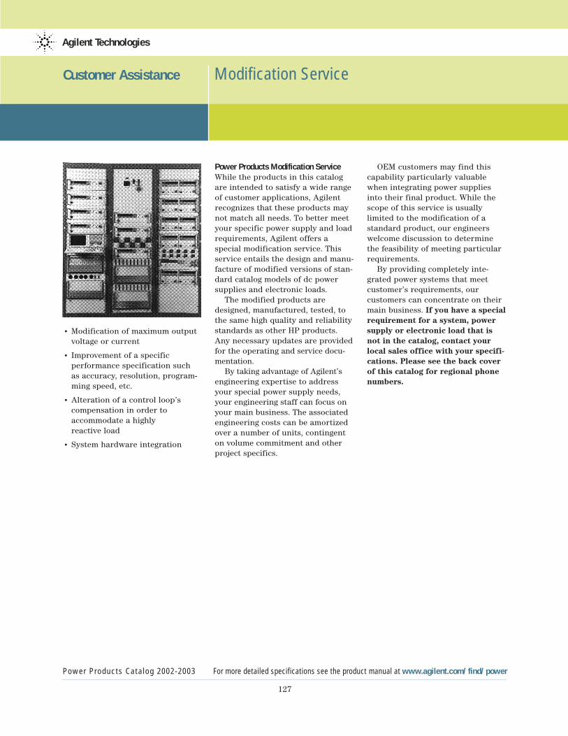
127
Customer Assistance Modification Service
Power Products Catalog 2002-2003 For more detailed specifications see the product manual at www.agilent.com/find/power
Agilent Technologies
• Modification of maximum output voltage or current
• Improvement of a specific performance specification suchas accuracy, resolution, program-ming speed, etc.
• Alteration of a control loop’s compensation in order toaccommodate a highly reactive load
• System hardware integration
Power Products Modification ServiceWhile the products in this catalogare intended to satisfy a wide rangeof customer applications, Agilentrecognizes that these products maynot match all needs. To better meetyour specific power supply and loadrequirements, Agilent offers a special modification service. Thisservice entails the design and manu-facture of modified versions of stan-dard catalog models of dc powersupplies and electronic loads.
The modified products aredesigned, manufactured, tested, tothe same high quality and reliabilitystandards as other HP products.Any necessary updates are providedfor the operating and service docu-mentation.
By taking advantage of Agilent’sengineering expertise to addressyour special power supply needs,your engineering staff can focus onyour main business. The associated engineering costs can be amortizedover a number of units, contingenton volume commitment and otherproject specifics.
OEM customers may find thiscapability particularly valuablewhen integrating power suppliesinto their final product. While thescope of this service is usually limited to the modification of astandard product, our engineers welcome discussion to determinethe feasibility of meeting particularrequirements.
By providing completely inte-grated power systems that meet customer’s requirements, our customers can concentrate on theirmain business. If you have a specialrequirement for a system, powersupply or electronic load that isnot in the catalog, contact yourlocal sales office with your specifi-cations. Please see the back coverof this catalog for regional phonenumbers.
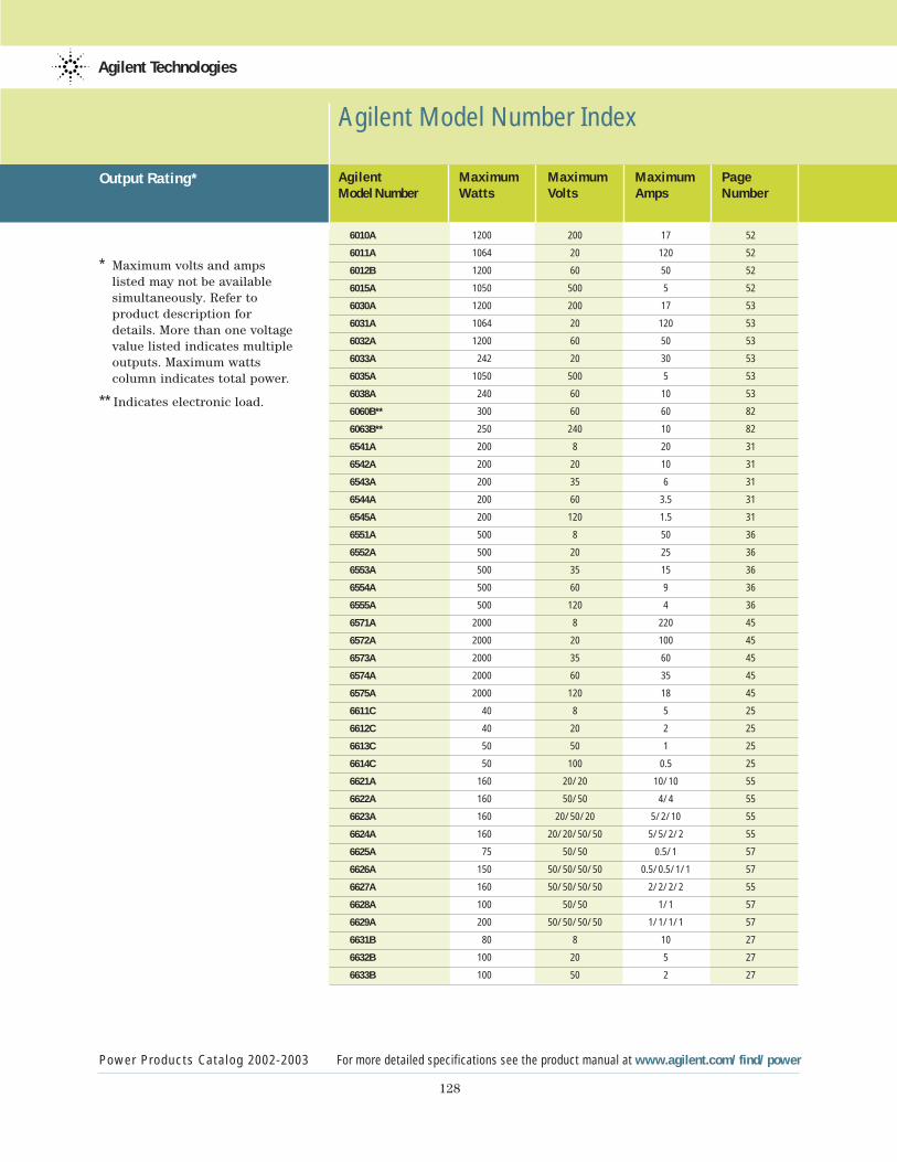
128
Agilent Model Number Index
Power Products Catalog 2002-2003 For more detailed specifications see the product manual at www.agilent.com/find/power
Agilent Technologies
* Maximum volts and amps listed may not be available simultaneously. Refer to product description for details. More than one voltage value listed indicates multipleoutputs. Maximum watts column indicates total power.
** Indicates electronic load.
Agilent Maximum Maximum Maximum PageModel Number Watts Volts Amps Number
6010A 1200 200 17 52
6011A 1064 20 120 52
6012B 1200 60 50 52
6015A 1050 500 5 52
6030A 1200 200 17 53
6031A 1064 20 120 53
6032A 1200 60 50 53
6033A 242 20 30 53
6035A 1050 500 5 53
6038A 240 60 10 53
6060B** 300 60 60 82
6063B** 250 240 10 82
6541A 200 8 20 31
6542A 200 20 10 31
6543A 200 35 6 31
6544A 200 60 3.5 31
6545A 200 120 1.5 31
6551A 500 8 50 36
6552A 500 20 25 36
6553A 500 35 15 36
6554A 500 60 9 36
6555A 500 120 4 36
6571A 2000 8 220 45
6572A 2000 20 100 45
6573A 2000 35 60 45
6574A 2000 60 35 45
6575A 2000 120 18 45
6611C 40 8 5 25
6612C 40 20 2 25
6613C 50 50 1 25
6614C 50 100 0.5 25
6621A 160 20/20 10/10 55
6622A 160 50/50 4/4 55
6623A 160 20/50/20 5/2/10 55
6624A 160 20/20/50/50 5/5/2/2 55
6625A 75 50/50 0.5/1 57
6626A 150 50/50/50/50 0.5/0.5/1/1 57
6627A 160 50/50/50/50 2/2/2/2 55
6628A 100 50/50 1/1 57
6629A 200 50/50/50/50 1/1/1/1 57
6631B 80 8 10 27
6632B 100 20 5 27
6633B 100 50 2 27
Output Rating*
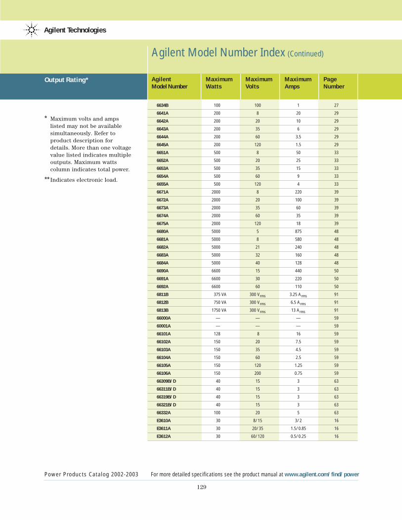
129
Agilent Model Number Index (Continued)
Power Products Catalog 2002-2003 For more detailed specifications see the product manual at www.agilent.com/find/power
Agilent Technologies
* Maximum volts and amps listed may not be available simultaneously. Refer to product description for details. More than one voltage value listed indicates multipleoutputs. Maximum watts column indicates total power.
** Indicates electronic load.
Agilent Maximum Maximum Maximum PageModel Number Watts Volts Amps Number
6634B 100 100 1 27
6641A 200 8 20 29
6642A 200 20 10 29
6643A 200 35 6 29
6644A 200 60 3.5 29
6645A 200 120 1.5 29
6651A 500 8 50 33
6652A 500 20 25 33
6653A 500 35 15 33
6654A 500 60 9 33
6655A 500 120 4 33
6671A 2000 8 220 39
6672A 2000 20 100 39
6673A 2000 35 60 39
6674A 2000 60 35 39
6675A 2000 120 18 39
6680A 5000 5 875 48
6681A 5000 8 580 48
6682A 5000 21 240 48
6683A 5000 32 160 48
6684A 5000 40 128 48
6690A 6600 15 440 50
6691A 6600 30 220 50
6692A 6600 60 110 50
6811B 375 VA 300 Vrms 3.25 Arms 91
6812B 750 VA 300 Vrms 6.5 Arms 91
6813B 1750 VA 300 Vrms 13 Arms 91
66000A — — — 59
60001A — — — 59
66101A 128 8 16 59
66102A 150 20 7.5 59
66103A 150 35 4.5 59
66104A 150 60 2.5 59
66105A 150 120 1.25 59
66106A 150 200 0.75 59
66309B/D 40 15 3 63
66311B/D 40 15 3 63
66319B/D 40 15 3 63
66321B/D 40 15 3 63
66332A 100 20 5 63
E3610A 30 8/15 3/2 16
E3611A 30 20/35 1.5/0.85 16
E3612A 30 60/120 0.5/0.25 16
Output Rating*
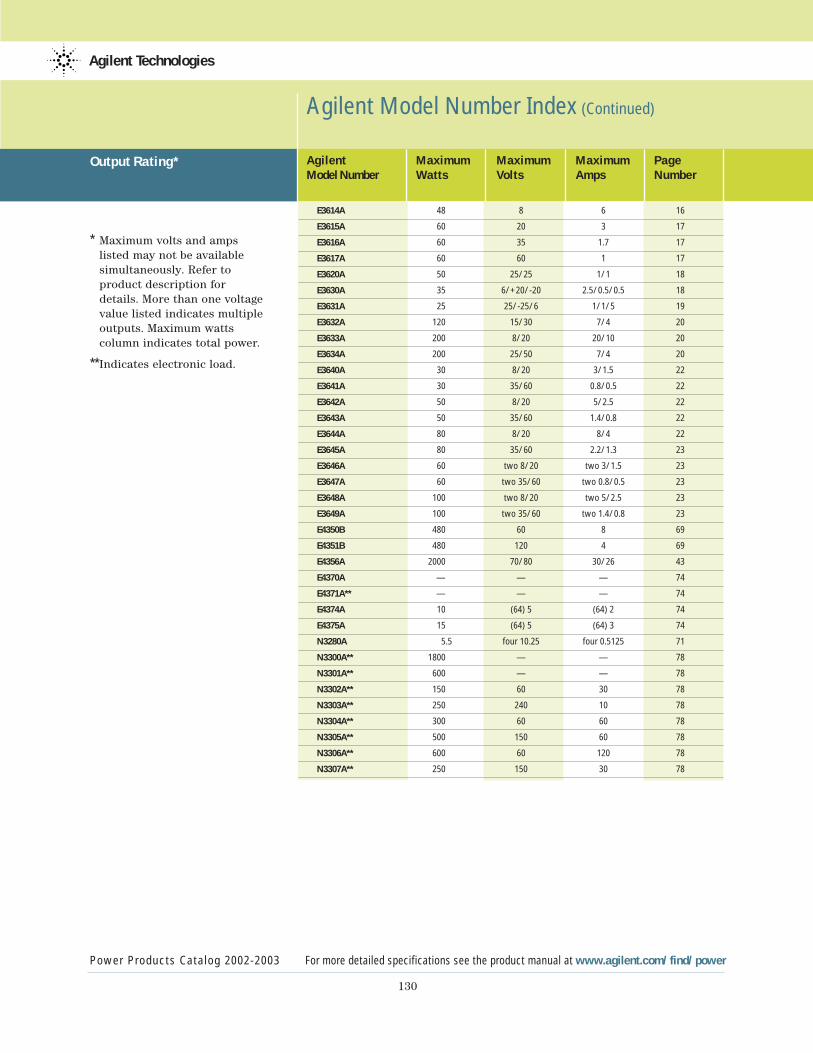
130
Agilent Model Number Index (Continued)
Power Products Catalog 2002-2003 For more detailed specifications see the product manual at www.agilent.com/find/power
Agilent Technologies
* Maximum volts and amps listed may not be available simultaneously. Refer to product description for details. More than one voltage value listed indicates multipleoutputs. Maximum watts column indicates total power.
**Indicates electronic load.
Agilent Maximum Maximum Maximum PageModel Number Watts Volts Amps Number
E3614A 48 8 6 16
E3615A 60 20 3 17
E3616A 60 35 1.7 17
E3617A 60 60 1 17
E3620A 50 25/25 1/1 18
E3630A 35 6/+20/-20 2.5/0.5/0.5 18
E3631A 25 25/-25/6 1/1/5 19
E3632A 120 15/30 7/4 20
E3633A 200 8/20 20/10 20
E3634A 200 25/50 7/4 20
E3640A 30 8/20 3/1.5 22
E3641A 30 35/60 0.8/0.5 22
E3642A 50 8/20 5/2.5 22
E3643A 50 35/60 1.4/0.8 22
E3644A 80 8/20 8/4 22
E3645A 80 35/60 2.2/1.3 23
E3646A 60 two 8/20 two 3/1.5 23
E3647A 60 two 35/60 two 0.8/0.5 23
E3648A 100 two 8/20 two 5/2.5 23
E3649A 100 two 35/60 two 1.4/0.8 23
E4350B 480 60 8 69
E4351B 480 120 4 69
E4356A 2000 70/80 30/26 43
E4370A — — — 74
E4371A** — — — 74
E4374A 10 (64) 5 (64) 2 74
E4375A 15 (64) 5 (64) 3 74
N3280A 5.5 four 10.25 four 0.5125 71
N3300A** 1800 — — 78
N3301A** 600 — — 78
N3302A** 150 60 30 78
N3303A** 250 240 10 78
N3304A** 300 60 60 78
N3305A** 500 150 60 78
N3306A** 600 60 120 78
N3307A** 250 150 30 78
Output Rating*
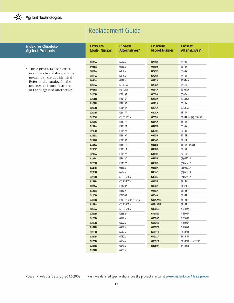
131
Replacement Guide
Power Products Catalog 2002-2003 For more detailed specifications see the product manual at www.agilent.com/find/power
Agilent Technologies
* These products are closest in ratings to the discontinued model, but are not identical. Refer to the catalog for the features and specifications of the suggested alternative.
Obsolete ClosestModel Number Alternatives*
6002A 664xA
6023A 6033A
6024A 6038A
6028A 6038A
6034A 6038A
6050A N3300A
6051A N3301A
6200B E3616A
6201B E3616A
6202B E3616A
6203B E3614A
6204B E2617A
6205C (2) E3611A
6206C E3617A
6211A E3612A
6212C E3612A
6213A E3610A
6214C E3610A
6215A E3611A
6216C E3611A
6217A E3612A
6218C E3612A
6220B E3617A
6224B 6453A
6226B 6544A
6227B (2) E3616A
6228B (2) E3617A
6234A E3620A
6235A E3630A
6236B E3630A
6237B E3611A and E3620A
6253A (2) E3615A
6255A (2) E3616A
6256B E6552A
6259B 6572A
6260B 6572A
6261B 6573A
6263B 6542A
6264B 6552A
6265B 6554A
6266B 6543A
6267B 6553A
Obsolete ClosestModel Number Alternatives*
6268B 6574A
6269B 6573A
6271B 6544A
6274B 6574A
6281A E3614A
6282A 6542A
6284A E3615A
6286A 6542A
6289A E3616A
6291A 6543A
6294A E3617A
6296A 6544A
6299A 6634B or (2) E3617A
6384A 6542A
6427B 6552A
6428B 6011A
6433B 6012B
6434B 6012B
6438B 6544A, 6634B
6439B 6012B
6448B 6015A
6453B (2) 6572A
6456B (2) 6572A
6459A (2) 6573A
6464C (2) 6681A
6466C (2) 6681A
6612B 6612C
6632A 6632B
6633A 6633B
6634A 6634B
6814A/B 6813B
6834A/B 6813B
60501B N3302A
60502B N3304A
60503B N3303A
60504B N3306A
60507B N3305A
66111A 66311B
66311A 66311B
66312A 66311D or 66319D
E4350A E4350B
Index for Obsolete Agilent Products
Agilent Technologies’ Test and Measurement Support, Services, and AssistanceAgilent Technologies aims to maximize the value you receive, while minimizing your risk and problems. We strive to ensure that you get the test and measurement capabilities you paid for and obtain the support you need. Our extensive support resources and services can helpyou choose the right Agilent products for your applications and apply them successfully. Everyinstrument and system we sell has a global warranty. Support is available for at least five yearsbeyond the production life of the product. Two concepts underlie Agilent’s overall support policy:“Our Promise” and “Your Advantage.”
Our PromiseOur Promise means your Agilent test and measurement equipment will meet its advertised perfor-mance and functionality. When you are choosing new equipment, we will help you with productinformation, including realistic performance specifications and practical recommendations fromexperienced test engineers. When you use Agilent equipment, we can verify that it works properly,help with product operation, and provide basic measurement assistance for the use of specified capabilities, at no extra cost upon request. Many self-help tools are available.
Your AdvantageYour Advantage means that Agilent offers a wide range of additional expert test and measure-ment services, which you can purchase according to your unique technical and business needs.Solve problems efficiently and gain a competitive edge by contracting with us for calibration,extra-cost upgrades, out-of-warranty repairs, and on-site education and training, as well as design, system integration, project management, and other professional engineering services.Experienced Agilent engineers and technicians worldwide can help you maximize your productiv-ity, optimize the return on investment of your Agilent instruments and systems, and obtaindependable measurement accuracy for the life of those products.
Agilent T&M Software and ConnectivityAgilent's Test and Measurement software and connectivity products,solutions and developer network allows you to take time out ofconnecting your instruments to your computer with tools based on PC standards, so you can focus on your tasks, not on your connections. Visit www.agilent.com/find/connectivity for more information.
For the latest information on Agilent’s Mobile Communications dc Sources, visit our web site at:www.agilent.com/find/mobilepower
By internet, phone, or fax, get assistance with all your test & measurement needs
Online assistance:www.agilent.com/find/assist
Phone or FaxUnited States:(tel) 1 800 452 4844
Canada:(tel) 1 877 894 4414(fax) (905) 282 6495
China:(tel) 800 810 0189(fax) 800 820 2816
Europe:(tel) (31 20) 547 2323(fax) (31 20) 547 2390
Japan:(tel) (81) 426 56 7832(fax) (81) 426 56 7840
Korea:(tel) (82 2) 2004 5004 (fax) (82 2) 2004 5115
Latin America:(tel) (305) 269 7500(fax) (305) 269 7599
Taiwan:(tel) 0800 047 866 (fax) 0800 286 331
Other Asia Pacific Countries:(tel) (65) 6375 8100(fax) (65) 6836 0252Email: [email protected]
Bluetooth and the Bluetooth logos are trade-marks owned by Bluetooth SIG, Inc., USA, andlicensed to Agilent Technologies, Inc.
Product specifications and descriptions in thisdocument subject to change without notice.© Agilent Technologies, Inc. 2002 Printed in the USA September 24, 2002 5988-7834EN
www.agilent.com
Agilent Email Updates
www.agilent.com/find/emailupdatesGet the latest information on the products and applications you select.
Agilent Technologies