Embed Size (px)
Citation preview
Agilent N6705A DC Power Analyzer
Biasing Multiple Input Voltage Devices in R&D
IntroductionThis application brief describes using the voltage output synchro-nization capabilities of modular power supplies in R&D multiple bias applications.
DescriptionDuring R&D and design validation stages, some tests begin with multiple, sequenced voltages to power the device under test (DUT). For example, an ATX PC mother-board requires a specifi c power-on sequence to power the board. It is important to power the board properly to avoid sub-assemblies drawing excessive current. An incor-rect power start-up sequence may cause damage to integrated circuits. In turn, this can compromise the reliability and quality of the circuit board. R&D engineers must generate the correct power-up sequence to the board to prevent harming circuits and causing additional problems.
Design validation engineers sequence multiple voltages to evaluate how much margin exists in their designs. They adjust the timing between the power-on voltages until a problem occurs.
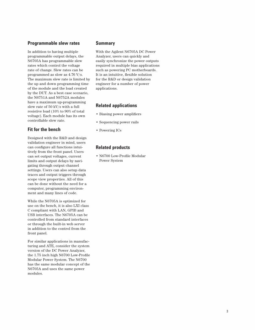
Figure 1 describes the input power timing sequence of an ATX moth-erboard. The ATX PC motherboard
Application Note
requires three power inputs with specifi c timing requirements before a digital PWR_OK signal is asserted. Once the board is powered, power is distributed to sub-assemblies on the board such as peripheral cards and drives. ASIC, FPGA and DSP test boards have similar power-on testing requirements in R&D and design validation.
+12 V/+5 V
t¹
+3.3 V 10%t¹
95%
10%
95%
t²
t³
PWR-OK
t4
Min. Max. (ms) (ms)t¹ 1 20t² 0 500t³ 100 500t4 1 10
Figure 1. An example of PC motherboard power-on timing requirements

2
ProblemThis test requires multiple power outputs for the 12 V, 5 V and 3.3 V lines with precise timing accuracy within the millisecond range. In addition, these power outputs need to have programmable slew rates to simulate the rate of change for the specifi ed timing conditions. Once the right power supplies with the right specifi cations and features are found, the power supplies are synchronized. Most engineers write programs in various programming environments to sequence the outputs during power on and off. This is a very time consuming task since the engineer needs to fi nd and install drivers, write code, debug their code, and characterize the timing between the outputs. Also, computer glitches and I/O lag time can cause inconsistencies in time synchronization.
Output sequencingThe N6705A has built-in output delay controls that are accessible from the front panel. As shown in Figure 2a, users can program output on and off delays by setting the time delay before the output turns on and off. This delay is applied after the All Outputs On or Off key is pressed. Users can enter delays from 0 ms to 1023 ms in 1 ms increments.
The example described in Figure 1 requires the 3.3 V voltage line to turn on at a time delayed by t
2 after the 12 V and 5 V voltage lines turn on. Here, the output on delays are referenced to the channel 1 voltage turning on. Figure 2b displays one example of a power-on sequence. The turn-on times refl ect the delays set in Figure 2a.
Note that the N6705A can also measure the current being drawn from the power modules and display it in scope view or by using the datalogger.
Solution: The Agilent N6705A DC Power AnalyzerThe Agilent N6705A DC Power Analyzer can precisely and repeatedly synchronize outputs. Designed for the bench, the DC Power Analyzer is an integrated instrument that has the capabilities of up to four power supplies, a function generator, an oscilloscope, a voltmeter, an ammeter and a datalogger in a single package. Intended for the R&D engineer, its intuitive design makes it quick to setup directly from the front panel. Over twenty different power supply modules can be mixed and matched to meet testing needs.
The 20+ different power modules have various voltage and current combinations organized in three different performance levels: basic performance, high-performance and precision. The high-performance and precision power modules, N675x and N676x respectively, have the fast programming times and accuracy specifi cations favored in this applica-tion. These modules have built-in output delay controls that can be confi gured directly from the front panel without the need to write a program.
Figure 2b. Screenshot of scope view on N6705A.Figure 2a. Screenshot of output delay controls on N6705A.
3
Programmable slew ratesIn addition to having multiple programmable output delays, the N6705A has programmable slew rates which control the voltage rate of change. Slew rates can be programmed as slow as 4.76 V/s. The maximum slew rate is limited by the up and down programming time of the module and the load created by the DUT. As a best case scenario, the N6751A and N6752A modules have a maximum up-programming slew rate of 50 kV/s with a full resistive load (10% to 90% of total voltage). Each module has its own controllable slew rate.
Fit for the benchDesigned with the R&D and design validation engineer in mind, users can confi gure all functions intui-tively from the front panel. Users can set output voltages, current limits and output delays by navi-gating through output channel settings. Users can also setup data traces and output triggers through scope view properties. All of this can be done without the need for a computer, programming environ-ment and many lines of code.
While the N6705A is optimized for use on the bench, it is also LXI class C compliant with LAN, GPIB and USB interfaces. The N6705A can be controlled from standard interfaces or through the built-in web server in addition to the control from the front panel.
For similar applications in manufac-turing and ATE, consider the system version of the DC Power Analyzer, the 1.75 inch high N6700 Low-Profi le Modular Power System. The N6700 has the same modular concept of the N6705A and uses the same power modules.
SummaryWith the Agilent N6705A DC Power Analyzer, users can quickly and easily synchronize the power outputs required in multiple bias applications such as powering PC motherboards. It is an intuitive, fl exible solution for the R&D or design validation engineer for a number of power applications.
Related applications• Biasing power amplifi ers
• Sequencing power rails
• Powering ICs
Related products• N6700 Low-Profi le Modular
Power System
Remove all doubtOur repair and calibration services will get your equipment back to you, performing like new, when promised. You will get full value out of your Agilent equipment throughout its lifetime. Your equipment will be serviced by Agilent-trained technicians using the latest factory calibration procedures, auto-mated repair diagnostics and genuine parts. You will always have the utmost confi dence in your measurements.
Agilent offers a wide range of additional expert test and measurement services for your equipment, including initial start-up assistance onsite education and training, as well as design, system integration, and project management.
For more information on repair and calibration services, go to
www.agilent.com/fi nd/removealldoubt
Agilent Email Updates
www.agilent.com/fi nd/emailupdatesGet the latest information on the products and applications you select.
Agilent Directwww.agilent.com/fi nd/agilentdirectQuickly choose and use your test equipment solutions with confi dence.
AgilentOpen
www.agilent.com/fi nd/openAgilent Open simplifies the process of connecting and programming test systems to help engineers design, validate and manufacture electronic products. Agilent offers open connectivity for a broad range of system-ready instruments, open industry software, PC-standard I/O and global support, which are combined to more easily integrate test system development.
www.lxistandard.orgLXI is the LAN-based successor to GPIB, providing faster, more effi cient connec-tivity. Agilent is a founding member of the LXI consortium.
www.agilent.comFor more information on Agilent Technologies’ products, applications or services, please contact your local Agilent offi ce. The complete list is available at:www.agilent.com/fi nd/contactus
AmericasCanada 877 894 4414Latin America 305 269 7500United States 800 829 4444
Asia Pacifi cAustralia 1 800 629 485China 800 810 0189Hong Kong 800 938 693India 1 800 112 929Japan 81 426 56 7832Korea 080 769 0800Malaysia 1 800 888 848Singapore 1 800 375 8100Taiwan 0800 047 866Thailand 1 800 226 008
EuropeAustria 0820 87 44 11Belgium 32 (0) 2 404 93 40 Denmark 45 70 13 15 15Finland 358 (0) 10 855 2100France 0825 010 700Germany 01805 24 6333* *0.14€/minuteIreland 1890 924 204 Italy 39 02 92 60 8484Netherlands 31 (0) 20 547 2111Spain 34 (91) 631 3300Sweden 0200-88 22 55Switzerland (French) 41 (21) 8113811 (Opt 2)Switzerland (German) 0800 80 53 53 (Opt 1)United Kingdom 44 (0) 118 9276201Other European Countries: www.agilent.com/fi nd/contactusRevised: May 7, 2007
Product specifi cations and descriptions in this document subject to change without notice.
© Agilent Technologies, Inc. 2007Printed in USA, May 21, 20075989-6454EN