Embed Size (px)
Citation preview
Agilent G1978A Multimode Source for G1946/G1956 LC/MSD
Set-Up Guide
Agilent Technologies
Notices© Agilent Technologies, Inc. 2008
No part of this manual may be reproduced in any form or by any means (including elec-tronic storage and retrieval or translation into a foreign language) without prior agree-ment and written consent from Agilent Technologies, Inc. as governed by United States and international copyright laws.
Manual Part NumberG1978-90050
EditionFirst Edition, December 2008
Printed in USA
Agilent Technologies, Inc. 5301 Stevens Creek Blvd. Santa Clara, CA 95051 USA
WarrantyThe material contained in this docu-ment is provided “as is,” and is sub-ject to being changed, without notice, in future editions. Further, to the max-imum extent permitted by applicable law, Agilent disclaims all warranties, either express or implied, with regard to this manual and any information contained herein, including but not limited to the implied warranties of merchantability and fitness for a par-ticular purpose. Agilent shall not be liable for errors or for incidental or consequential damages in connec-tion with the furnishing, use, or per-formance of this document or of any information contained herein. Should Agilent and the user have a separate written agreement with warranty terms covering the material in this document that conflict with these terms, the warranty terms in the sep-arate agreement shall control.
Technology Licenses The hardware and/or software described in this document are furnished under a license and may be used or copied only in accor-dance with the terms of such license.
Restricted Rights LegendU.S. Government Restricted Rights. Soft-ware and technical data rights granted to the federal government include only those rights customarily provided to end user cus-tomers. Agilent provides this customary commercial license in Software and techni-cal data pursuant to FAR 12.211 (Technical Data) and 12.212 (Computer Software) and, for the Department of Defense, DFARS 252.227-7015 (Technical Data - Commercial Items) and DFARS 227.7202-3 (Rights in Commercial Computer Software or Com-puter Software Documentation).
Safety Notices
CAUTION
A CAUTION notice denotes a haz-ard. It calls attention to an operat-ing procedure, practice, or the like that, if not correctly performed or adhered to, could result in damage to the product or loss of important data. Do not proceed beyond a CAUTION notice until the indicated conditions are fully understood and met.
WARNING
A WARNING notice denotes a hazard. It calls attention to an operating procedure, practice, or the like that, if not correctly per-formed or adhered to, could result in personal injury or death. Do not proceed beyond a WARNING notice until the indicated condi-tions are fully understood and met.
Windows® and MS Windows® are U.S. registered trademarks of Microsoft Corpora-tion.
Windows NT® is a U.S. registered trade-mark of Microsoft Corporation.
2 Multimode Source for G1946/G1956 LC/MSD Set-Up Guide
In This Guide
Multimode Source f
This guide explains how to install, maintain and troubleshoot your nanoelectospray ion source.
1
InstallationThis chapter tells you how to install the multimode ion source.
2
VerificationThis chapter tells you how to install the multimode ion source.
3
MethodsThis chapter describes basic operation and maintenance for the multimode ion source.
or G1946/G1956 LC/MSD Set-Up Guide 3

4
Multimode Source for G1946/G1956 LC/MSD Set-Up Guide
Contents
Content
1 Installation 7
Installation 9
Step 1. Prepare to install 9Step 2. Check the instrument board revisions 10Step 3. Turn off the instrument 10Step 4. Change chips on electronic boards (CE Only) 11Step 5. Convert from ESI, APCI or APPI to multimode source 16Step 6. Upgrade the software with the G1978-10002 patch 16Step 7. Check instrument boards 19Step 8. Verify performance of the multimode source 22
Changing Sources 23
To convert from ESI, APCI or APPI to the multimode source 23To install the HV control PCA 30To connect multimode source cables 34To remove the multimode source 38To convert from multimode to ESI, APCI or APPI 41
2 Verification 43
To determine proper solvent mixture for performance verification 44To prepare performance evaluation samples 45To verify multimode source operations 51To do an autotune 56Example of multimode verification report 57
3 Methods 59
To setup a method to use the multimode source 60To create a method for positive/negative mixed mode operation 61To create a method for alternating ESI and APCI operation 63
Multimode Source for G1946/G1956 LC/MSD Set-Up Guide 5

Contents
6 Multimode Source for G1946/G1956 LC/MSD Set-Up Guide
Agilent G1978A Multimode Source for G1946/G1956 LC/MSDSet-Up Guide
1Installation
Installation 9
Step 1. Prepare to install 9
Step 2. Check the instrument board revisions 10
Step 3. Turn off the instrument 10
Step 4. Change chips on electronic boards (CE Only) 11
Step 5. Convert from ESI, APCI or APPI to multimode source 16
Step 6. Upgrade the software with the G1978-10002 patch 16
Step 7. Check instrument boards 19
Step 8. Verify performance of the multimode source 22
Changing Sources 23
To convert from ESI, APCI or APPI to the multimode source 23
To install the HV control PCA 30
To connect multimode source cables 34
To remove the multimode source 38
To convert from multimode to ESI, APCI or APPI 41
This chapter contains instructions to install the G1978A multimode source on the G1946 and G1956 LC/MSD instruments. (The G1978B source is not supported on the G1946/G1956 instruments.)
The instructions of this manual are supported with LC/MSD ChemStation Release B.01.01 or B.01.03, with G1978-10002 update patch or higher. The patch installation CD contains both a B.01.01 and B.01.03 folder, each containing a setup.exe file. Run the appropriate setup.exe file, depending on your ChemStation release number.
7Agilent Technologies
8
1 Installation
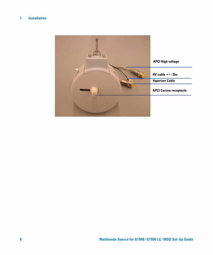
APCI Corona receptacle
Vaporizer Cable
HV cable +/- 2kv
APCI High voltage
Multimode Source for G1946/G
1 956 LC/MSD Set-Up Guide
Installation 1 Installation
Installation
Multimode Source f
This section contains instructions to install the G1978A multimode source onto the G1946 or G1956 LC/MSD instrument.
Step 1. Prepare to install
Before you install the multimode source, check that you have the appropriate parts and tools.
1 Check that you have these parts:
• Bundled LC/MSD Multimode ESI/APCI Source (p/n G1978A)
• LC/MSD Multimode ESI/APCI Source (p/n G1978-65239)
• Multimode HV Module Assembly (p/n G1978-60050)
• LCMSD MM ESI/APCI Enablement Kit (p/n G1978-60150)
• Firmware Upgrade Kit, MM (p/n G1978-60156)
• ChemStation B.01.01 or B.01.03 or greater
• Patch (p/n G1978-10002). The software patch is included in G1978A and is required for both B.01.01 and B.01.03.
NOTE All G1946B/C/D and G1956A/B MSD instruments that were installed before the multimode source was released will need to be on ChemStation B.01.01 or greater to install the multimode source hardware, firmware, new PID values, and software patch.
2 Check that you have these tools, supplies and chemicals. The items in this list are not provided with your multimode source.
• Cloths and gloves, clean, lint-free
• Water and organics, such as acetone, methanol, acetonitrile or isopropyl alcohol, all HPLC grade
• ¼ inch open-end wrench
• Torx drive T10
or G1946/G1956 LC/MSD Set-Up Guide 9
1 Installation Step 2. Check the instrument board revisions
Step 2. Check the instrument board revisions
10
The software allows you to check to see if the instrument boards have been updated.
Analyzer 3 board
Do the following steps to determine if you have an Analyzer 3 board installed.
1 In the Method and Run Control view on the command line, type
• pat$=nvrAnRev$()
2 On the command line type
• Print pat$
The part number for the analyzer board will print on the message line. If the part number is G1946-60250, the board that is installed is an Analyzer 3 board. If a different part number is printed, you will need to upgrade to the Analyzer 3 board.
Power distribution board (PDB)
The Power distribution board on all G1956A/B & G1946B/C/D are already the correct board (p/n G1946-60002).
Step 3. Turn off the instrument
• Refer to the instructions for your instrument to properly turn off the instrument.
NOTE Shut down the instrument completely if not a bundled installation. This includes G1946B/C/D and pre-multimode G1956A/B instruments. These instruments are considered upgrades for use with the G1978A source.
Multimode Source for G1946/G1956 LC/MSD Set-Up Guide
Installation 1 Step 4. Change chips on electronic boards (CE Only)
Step 4. Change chips on electronic boards (CE Only)
Multimode Source f
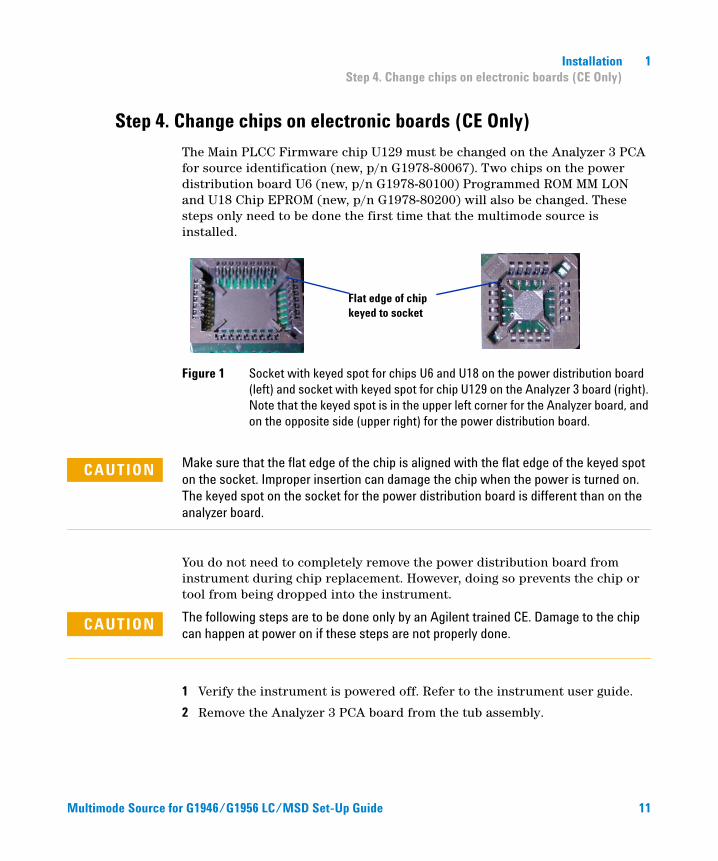
The Main PLCC Firmware chip U129 must be changed on the Analyzer 3 PCA for source identification (new, p/n G1978-80067). Two chips on the power distribution board U6 (new, p/n G1978-80100) Programmed ROM MM LON and U18 Chip EPROM (new, p/n G1978-80200) will also be changed. These steps only need to be done the first time that the multimode source is installed.
Figure 1 Socket with keyed spot for chips U6 and U18 on the power distribution board (left) and socket with keyed spot for chip U129 on the Analyzer 3 board (right). Note that the keyed spot is in the upper left corner for the Analyzer board, and on the opposite side (upper right) for the power distribution board.
Flat edge of chip keyed to socket
CAUTION Make sure that the flat edge of the chip is aligned with the flat edge of the keyed spot on the socket. Improper insertion can damage the chip when the power is turned on. The keyed spot on the socket for the power distribution board is different than on the analyzer board.
You do not need to completely remove the power distribution board from instrument during chip replacement. However, doing so prevents the chip or tool from being dropped into the instrument.
The following steps are to be done only by an Agilent trained CE. Damage to the chip
CAUTIONcan happen at power on if these steps are not properly done.1 Verify the instrument is powered off. Refer to the instrument user guide.
2 Remove the Analyzer 3 PCA board from the tub assembly.
or G1946/G1956 LC/MSD Set-U
p Guide 11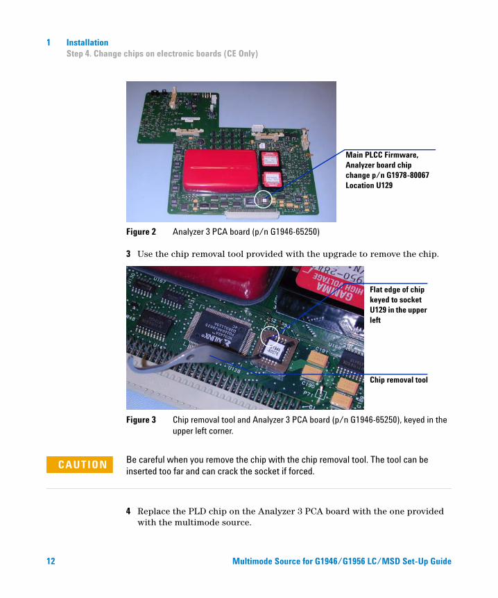
12
1 Installation Step 4. Change chips on electronic boards (CE Only)
Figure 2 Analyzer 3 PCA board (p/n G1946-65250)
3 Use the chip removal tool provided with the upgrade to remove the chip.
Figure 3 Chip removal tool and Analyzer 3 PCA board (p/n G1946-65250), keyed in the upper left corner.
Main PLCC Firmware, Analyzer board chip change p/n G1978-80067 Location U129
Flat edge of chip keyed to socket U129 in the upper left
Chip removal tool
CAUTION Be careful when you remove the chip with the chip removal tool. The tool can be inserted too far and can crack the socket if forced.
4 Replace the PLD chip on the Analyzer 3 PCA board with the one provided with the multimode source.
Multimode Source for G1946/
G195 6 LC/MSD Set-Up Guide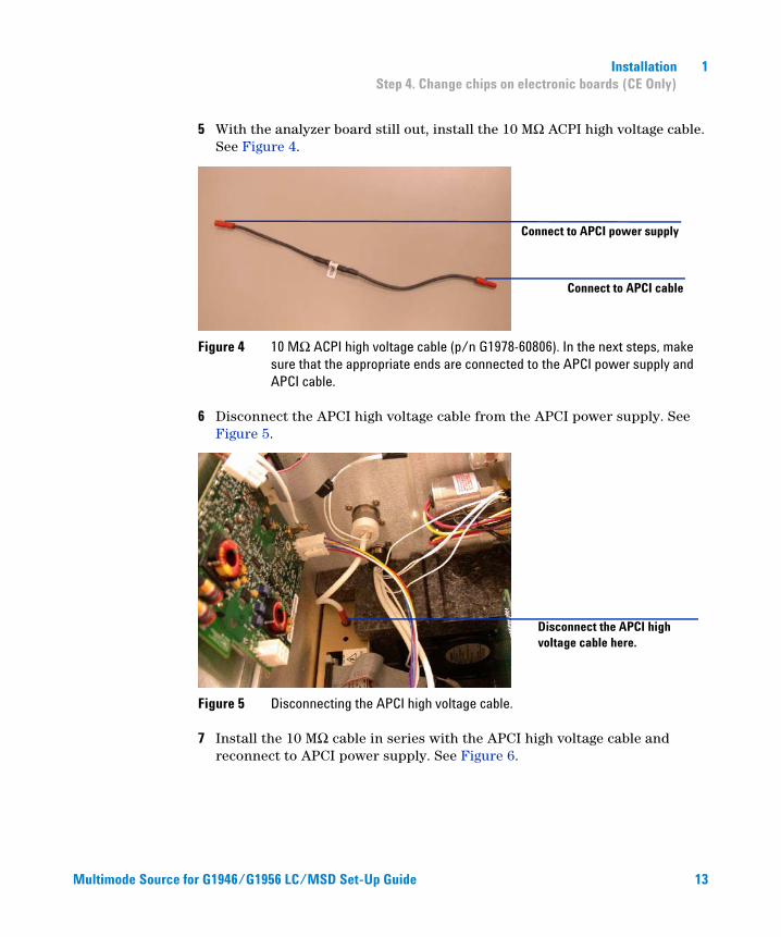
Multimode Source f
Installation 1 Step 4. Change chips on electronic boards (CE Only)
5 With the analyzer board still out, install the 10 MΩ ACPI high voltage cable. See Figure 4.
Figure 4 10 MΩ ACPI high voltage cable (p/n G1978-60806). In the next steps, make sure that the appropriate ends are connected to the APCI power supply and APCI cable.
6 Disconnect the APCI high voltage cable from the APCI power supply. See Figure 5.
Figure 5 Disconnecting the APCI high voltage cable.
7 Install the 10 MΩ cable in series with the APCI high voltage cable and reconnect to APCI power supply. See Figure 6.
Connect to APCI cable
Connect to APCI power supply
Disconnect the APCI high voltage cable here.
or G1946/G1956 LC/MSD Set-Up Guide
13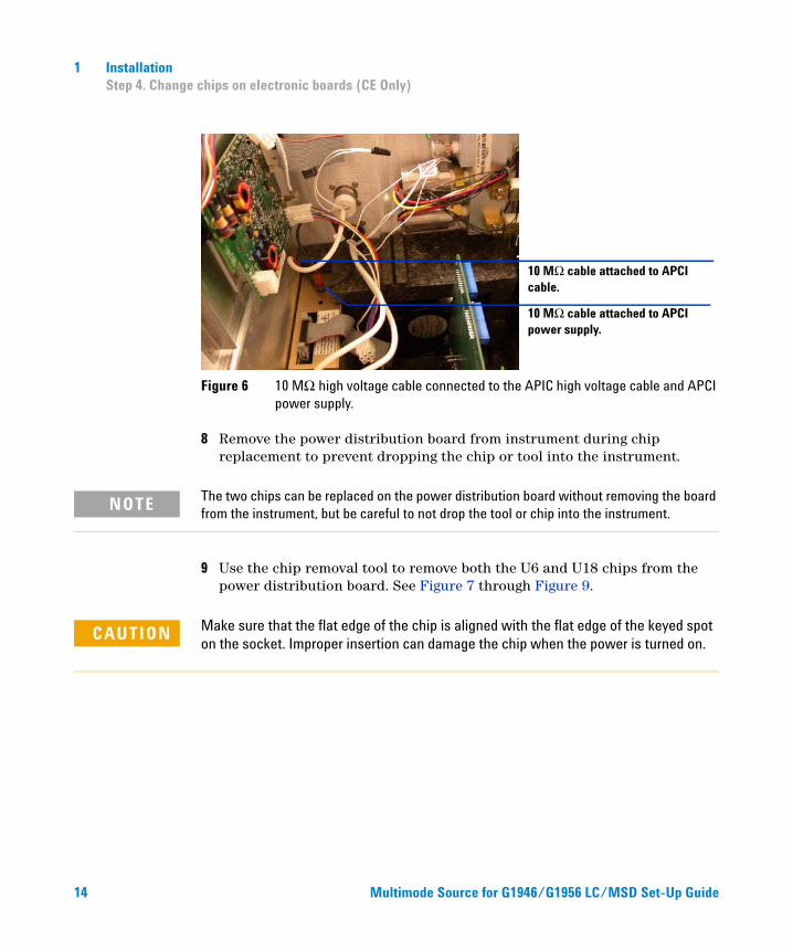
14
1 Installation Step 4. Change chips on electronic boards (CE Only)
Figure 6 10 MΩ high voltage cable connected to the APIC high voltage cable and APCI power supply.
8 Remove the power distribution board from instrument during chip replacement to prevent dropping the chip or tool into the instrument.
10 MΩ cable attached to APCI cable.
10 MΩ cable attached to APCI power supply.
NOTE The two chips can be replaced on the power distribution board without removing the board from the instrument, but be careful to not drop the tool or chip into the instrument.
9 Use the chip removal tool to remove both the U6 and U18 chips from the power distribution board. See Figure 7 through Figure 9.
CAUTION Make sure that the flat edge of the chip is aligned with the flat edge of the keyed spot on the socket. Improper insertion can damage the chip when the power is turned on.
Multimode Source for G1
946/G1956 LC/MSD Set-Up Guide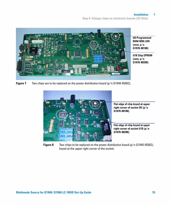
Installation 1 Step 4. Change chips on electronic boards (CE Only)
Figure 7 Two chips are to be replaced on the power distribution board (p/n G1946-65002).
U18 Chip EPROM (new, p/n G1978-80200)
U6 Programmed ROM MM LON (new, p/n G1978-80100)
Multimode Source f
Figure 8 Two chips to be replaced on the power distribution board (p/n G1946-65002), keyed at the upper right corner of the socket.
Flat edge of chip keyed at upper right corner of socket U6 (p/n G1978-80100)
Flat edge of chip keyed at upper right corner of socket U18 (p/n G1978-80200)
or G1946/G1956 LC/MSD Set-Up Guide
15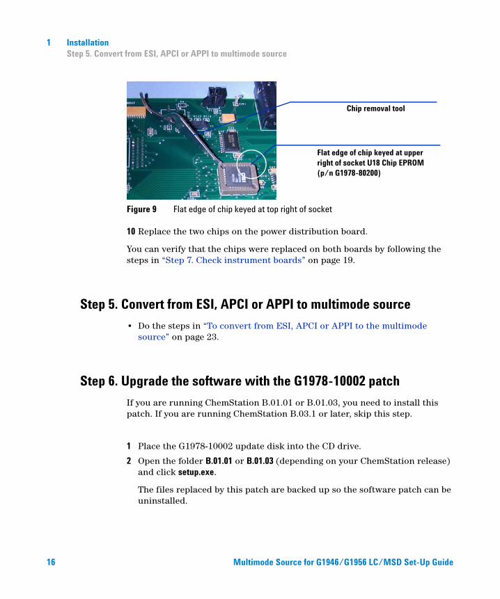
16
1 Installation Step 5. Convert from ESI, APCI or APPI to multimode source
Figure 9 Flat edge of chip keyed at top right of socket
10 Replace the two chips on the power distribution board.
You can verify that the chips were replaced on both boards by following the steps in “Step 7. Check instrument boards” on page 19.
Chip removal tool
Flat edge of chip keyed at upper right of socket U18 Chip EPROM (p/n G1978-80200)
Step 5. Convert from ESI, APCI or APPI to multimode source
• Do the steps in “To convert from ESI, APCI or APPI to the multimode source” on page 23.
Step 6. Upgrade the software with the G1978-10002 patch
If you are running ChemStation B.01.01 or B.01.03, you need to install this patch. If you are running ChemStation B.03.1 or later, skip this step.
1 Place the G1978-10002 update disk into the CD drive.
2 Open the folder B.01.01 or B.01.03 (depending on your ChemStation release) and click setup.exe.
The files replaced by this patch are backed up so the software patch can be uninstalled.
Multimode Source for G1946
/G1956 LC/MSD Set-Up Guide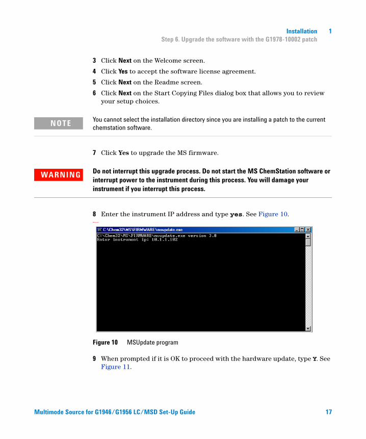
Multimode Source f
Installation 1 Step 6. Upgrade the software with the G1978-10002 patch
3 Click Next on the Welcome screen.
4 Click Yes to accept the software license agreement.
5 Click Next on the Readme screen.
6 Click Next on the Start Copying Files dialog box that allows you to review your setup choices.
NOTE You cannot select the installation directory since you are installing a patch to the current chemstation software.
7 Click Yes to upgrade the MS firmware.
WARNING Do not interrupt this upgrade process. Do not start the MS ChemStation software or interrupt power to the instrument during this process. You will damage your instrument if you interrupt this process.
8 Enter the instrument IP address and type yes. See Figure 10.MSUpdate
Figure 10 MSUpdate program
9 When prompted if it is OK to proceed with the hardware update, type Y. See Figure 11.
or G1946/G1956 LC/MSD Set-Up Guide 17
18
1 Installation Step 6. Upgrade the software with the G1978-10002 patch
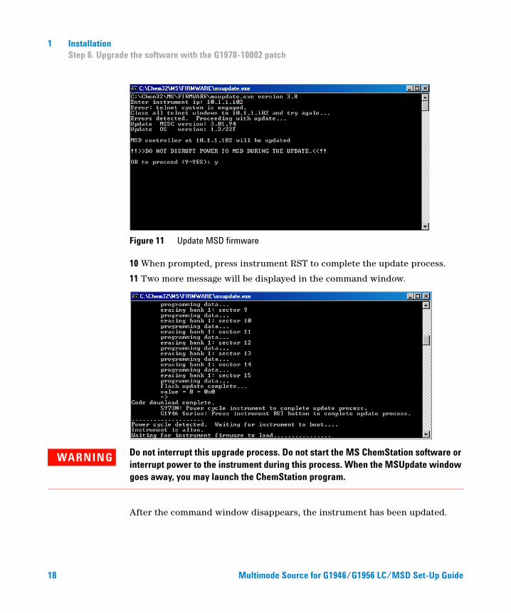
Figure 11 Update MSD firmware
10 When prompted, press instrument RST to complete the update process.
11 Two more message will be displayed in the command window.
WARNING Do not interrupt this upgrade process. Do not start the MS ChemStation software or interrupt power to the instrument during this process. When the MSUpdate window goes away, you may launch the ChemStation program.
After the command window disappears, the instrument has been updated.
Multimode Source for G1946/G1956 LC/MSD Set-Up Guide
Installation 1 Step 7. Check instrument boards
Step 7. Check instrument boards
Multimode Source f
To validate that the new PID values were changed.
1 Launch the ChemStation. The pid2.mac changes the PID values automatically when the ChemStation starts up.
2 In the Method and Run Control view on the command line enter:
• MSZONEPID 7
The following information will be shown on the message line:
P = 2500
I = 1
D = 0
I_D = 1
To validate the changes to the chips on the Analyzer 3 and the Power distribution boards
Do the following steps to validate that the chips on the Analyzer 3 board (p/n G1946-65250) and the power distribution board (p/n G1946-65002) were updated to support the multimode source. If either the ChemStation version B.01.01 or B01.03 with G1978-10002 multimode update software disk has been loaded, the macro mstnnvr.mac will be updated and returns more information.
1 At the command line in the Method and Run Control view, type
mmcheck = MMBoardUpdate()
2 Type the command below at the command line, then press Enter.
Print mmcheck
If the variable mmcheck has the value 0, both boards have been updated.
If the variable mmcheck has the value 1, one board has not been updated.
If the variable mmcheck has the value 2, neither board has been updated.
3 To validate all firmware chip revisions:
• Type readnvr and press Enter.
• Type shownvr or printnvr and press Enter.
or G1946/G1956 LC/MSD Set-Up Guide 19
20
1 Installation Step 7. Check instrument boards
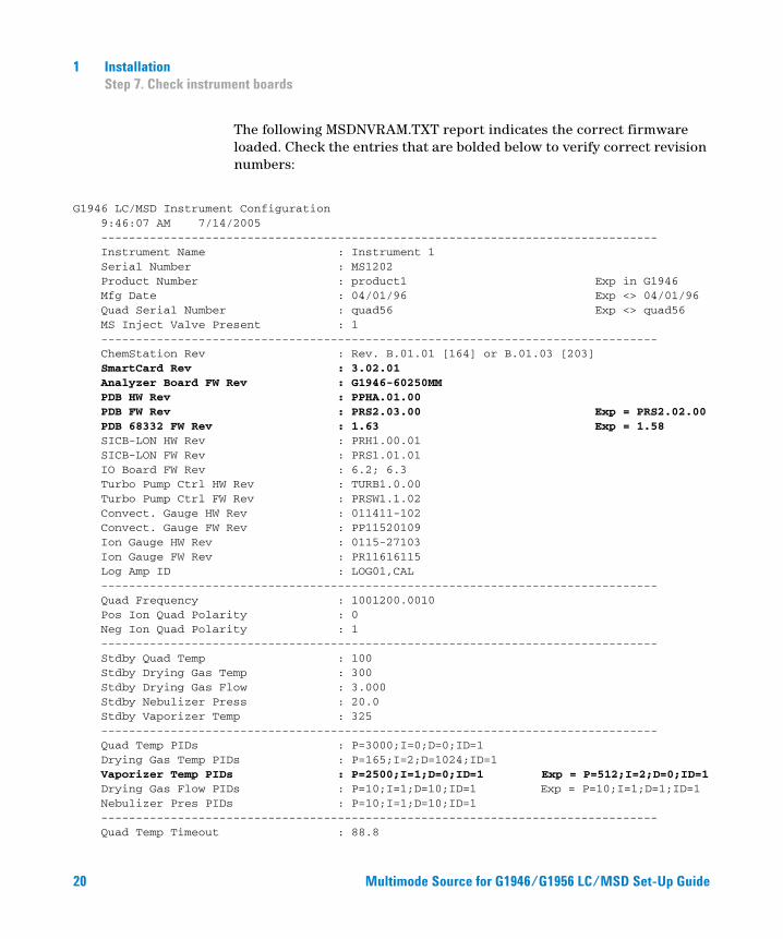
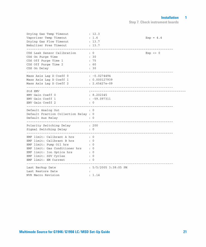
The following MSDNVRAM.TXT report indicates the correct firmware loaded. Check the entries that are bolded below to verify correct revision numbers:
rument Configuration
G1946 LC/MSD Inst 9:46:07 AM 7/14/2005 -------------------------------------------------------------------------------- Instrument Name : Instrument 1 Serial Number : MS1202 Product Number : product1 Exp in G1946 Mfg Date : 04/01/96 Exp <> 04/01/96 Quad Serial Number : quad56 Exp <> quad56 MS Inject Valve Present : 1 -------------------------------------------------------------------------------- ChemStation Rev : Rev. B.01.01 [164] or B.01.03 [203] SmartCard Rev : 3.02.01 Analyzer Board FW Rev : G1946-60250MM PDB HW Rev : PPHA.01.00 PDB FW Rev : PRS2.03.00 Exp = PRS2.02.00 PDB 68332 FW Rev : 1.63 Exp = 1.58 SICB-LON HW Rev : PRH1.00.01 SICB-LON FW Rev : PRS1.01.01 IO Board FW Rev : 6.2; 6.3 Turbo Pump Ctrl HW Rev : TURB1.0.00 Turbo Pump Ctrl FW Rev : PRSW1.1.02 Convect. Gauge HW Rev : 011411-102 Convect. Gauge FW Rev : PP11520109 Ion Gauge HW Rev : 0115-27103 Ion Gauge FW Rev : PR11616115 Log Amp ID : LOG01,CAL -------------------------------------------------------------------------------- Quad Frequency : 1001200.0010 Pos Ion Quad Polarity : 0 Neg Ion Quad Polarity : 1 -------------------------------------------------------------------------------- Stdby Quad Temp : 100 Stdby Drying Gas Temp : 300 Stdby Drying Gas Flow : 3.000 Stdby Nebulizer Press : 20.0 Stdby Vaporizer Temp : 325 -------------------------------------------------------------------------------- Quad Temp PIDs : P=3000;I=0;D=0;ID=1 Drying Gas Temp PIDs : P=165;I=2;D=1024;ID=1 Vaporizer Temp PIDs : P=2500;I=1;D=0;ID=1 Exp = P=512;I=2;D=0;ID=1 Drying Gas Flow PIDs : P=10;I=1;D=10;ID=1 Exp = P=10;I=1;D=1;ID=1 Nebulizer Pres PIDs : P=10;I=1;D=10;ID=1 -------------------------------------------------------------------------------- Quad Temp Timeout : 88.8Multimode Source for G1946/G1956 LC/MSD Set-Up Guide
Installation 1 Step 7. Check instrument boards
Drying Gas Temp Timeout : 12.3 Vaporizer Temp Timeout : 1.6 Exp = 4.4 Drying Gas Flow Timeout : 13.7 Nebulizer Pres Timeout : 13.7 -------------------------------------------------------------------------------- CDS Leak Sensor Calibration : 0 Exp <> 0 CDS On Purge Time : 30 CDS Off Purge Time 1 : 75 CDS Off Purge Time 2 : 60 CDS On Delay : 30 -------------------------------------------------------------------------------- Mass Axis Lag D Coeff 0 : -0.0274494 Mass Axis Lag D Coeff 1 : 0.000127939 Mass Axis Lag D Coeff 2 : 2.65427e-09 -------------------------------------------------------------------------------- Std EMV :---------------------------------------------------- EMV Gain Coeff 0 : 8.202345 EMV Gain Coeff 1 : -59.097311 EMV Gain Coeff 2 : 0 -------------------------------------------------------------------------------- Default Analog Out : 0 Default Fraction Collection Relay : 0 Default Aux Relay : 0 -------------------------------------------------------------------------------- Polarity Switching Delay : 200 Signal Switching Delay : 0 -------------------------------------------------------------------------------- EMF limit: Calibrant A hrs : 0 EMF limit: Calibrant B hrs : 0 EMF limit: Pump Oil hrs : 0 EMF limit: Gas Conditioner hrs : 0 EMF limit: Ion Optics hrs : 0 EMF limit: SSV Cycles : 0 EMF limit: EM Current : 0 -------------------------------------------------------------------------------- Last Backup Date : 5/5/2005 3:38:05 PM Last Restore Date : NVR Macro Revision : 1.14
Multimode Source for G1946/G1956 LC/MSD Set-Up Guide 21
1 Installation Step 8. Verify performance of the multimode source
Step 8. Verify performance of the multimode source
22
Before using your system, verify the performance of your system.
1 Start the ChemStation software.
2 Do the steps in “To do an autotune” on page 56.
3 Bake out the instrument. Refer to the multimode Maintenance Guide.
4 Do the steps in “To prepare performance evaluation samples” on page 45.
NOTE These verification methods are to be used for sensitivity verification for bundled instruments shipped with a multimode source only.
5 Do the steps in “To verify multimode source operations” on page 51.
Multimode Source for G1946/G1956 LC/MSD Set-Up Guide
Installation 1 Changing Sources
Changing Sources
Multimode Source f
This section includes tasks that you will need to do change the source on your instrument.
To convert from ESI, APCI or APPI to the multimode source
CAUTION If you are installing this source on this instrument for the first time, follow the steps in “Installation” on page 7.
1 Switch to the MSD Tune view.
2 Select Instrument/Set Spray Chamber and set all gas flows and temperatures to 0.
• Drying Gas (L/min)
• Nebulizer Pressure (psig)
• Drying Gas Temperature (°C)
• Vaporizer Temperature (APCI source only)
• Lamp Off (APPI source only)
3 Wait for the source to cool (until temperatures are at least below 100 °C).
4 Disconnect the nebulizer gas tubing from the currently installed ion source.
5 Disconnect the LC/MSD sample inlet tubing.
6 If the APCI or APPI source is installed, remove the APCI vaporizer heater cable and APCI high voltage cable.
7 If the APPI source is installed, remove the serial port B RS-232 cable.
8 Remove the currently installed ion source.
or G1946/G1956 LC/MSD Set-Up Guide 23
24
1 Installation To convert from ESI, APCI or APPI to the multimode source
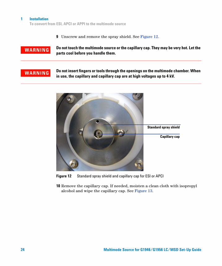
9 Unscrew and remove the spray shield. See Figure 12.
WARNING Do not touch the multimode source or the capillary cap. They may be very hot. Let the parts cool before you handle them.
WARNING Do not insert fingers or tools through the openings on the multimode chamber. When in use, the capillary and capillary cap are at high voltages up to 4 kV.
Figure 12 Standard spray shield and capillary cap for ESI or APCI
10 Remove the capillary cap. If needed, moisten a clean cloth with isopropyl alcohol and wipe the capillary cap. See Figure 13.
Standard spray shield
Capillary cap
Multimode Source for G1946/G1956 LC/MSD Set-Up Guide
Installation 1 To convert from ESI, APCI or APPI to the multimode source
Multimode Source f
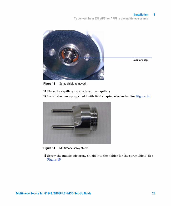
Figure 13 Spray shield removed.
11 Place the capillary cap back on the capillary.
12 Install the new spray shield with field shaping electrodes. See Figure 14.
Figure 14 Multimode spray shield
13 Screw the multimode spray shield into the holder for the spray shield. See Figure 15
Capillary cap
or G1946/G1956 LC/MSD Set-Up Guide
25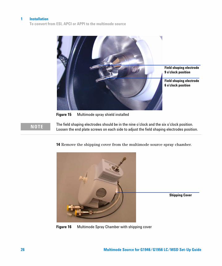
26
1 Installation To convert from ESI, APCI or APPI to the multimode source
Figure 15 Multimode spray shield installed
Field shaping electrode 9 o'clock position
Field shaping electrode 6 o'clock position
NOTE The field shaping electrodes should be in the nine o’clock and the six o’clock position. Loosen the end plate screws on each side to adjust the field shaping electrodes position.
14 Remove the shipping cover from the multimode source spray chamber.
Figure 16 Multimode Spray Chamber with shipping cover
Shipping Cover
Multimode Source for G1946/G19
5 6 LC /MSD Set-Up Guide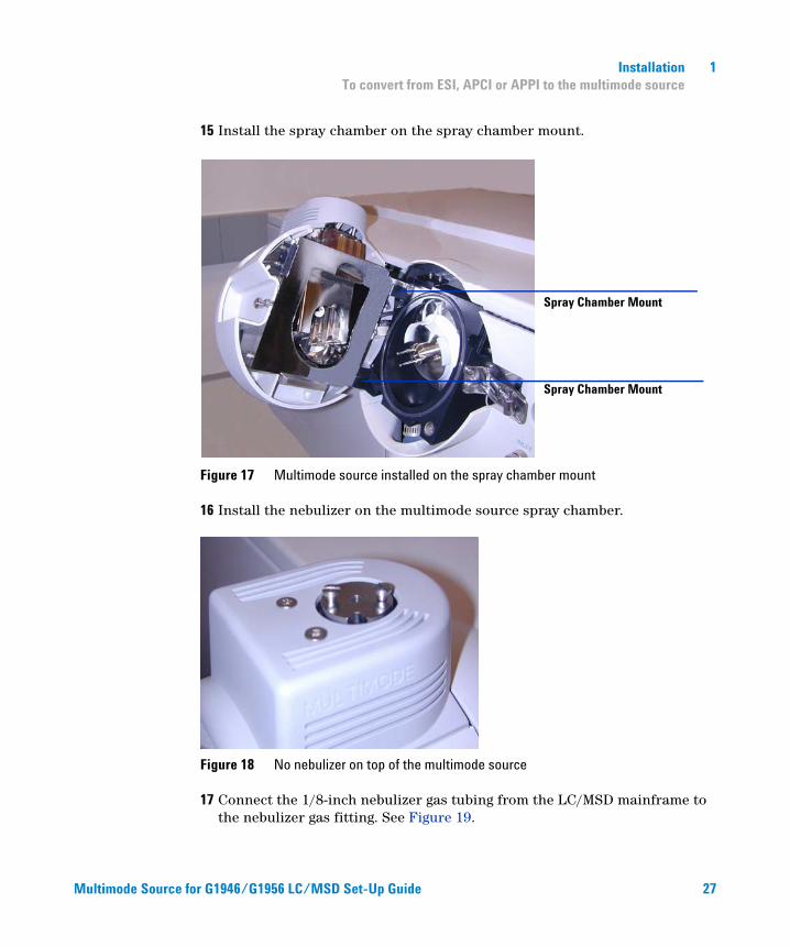
Multimode Source f
Installation 1 To convert from ESI, APCI or APPI to the multimode source
15 Install the spray chamber on the spray chamber mount.
Figure 17 Multimode source installed on the spray chamber mount
16 Install the nebulizer on the multimode source spray chamber.
Figure 18 No nebulizer on top of the multimode source
17 Connect the 1/8-inch nebulizer gas tubing from the LC/MSD mainframe to the nebulizer gas fitting. See Figure 19.
Spray Chamber Mount
Spray Chamber Mount
or G1946/G1956 LC/MSD Set-Up Guide
27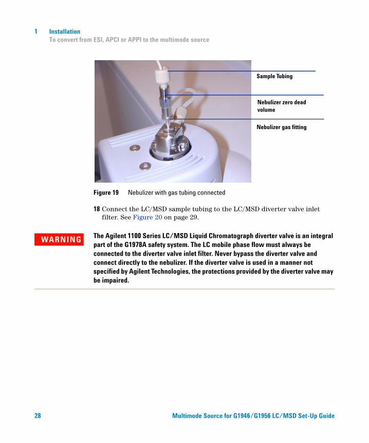
28
1 Installation To convert from ESI, APCI or APPI to the multimode source
Figure 19 Nebulizer with gas tubing connected
18 Connect the LC/MSD sample tubing to the LC/MSD diverter valve inlet filter. See Figure 20 on page 29.
Sample Tubing
Nebulizer zero dead volume
Nebulizer gas fitting
WARNING The Agilent 1100 Series LC/MSD Liquid Chromatograph diverter valve is an integral part of the G1978A safety system. The LC mobile phase flow must always be connected to the diverter valve inlet filter. Never bypass the diverter valve and connect directly to the nebulizer. If the diverter valve is used in a manner not specified by Agilent Technologies, the protections provided by the diverter valve may be impaired.
Multimode Source for G1946/
G1956 LC/MSD Set-Up Guide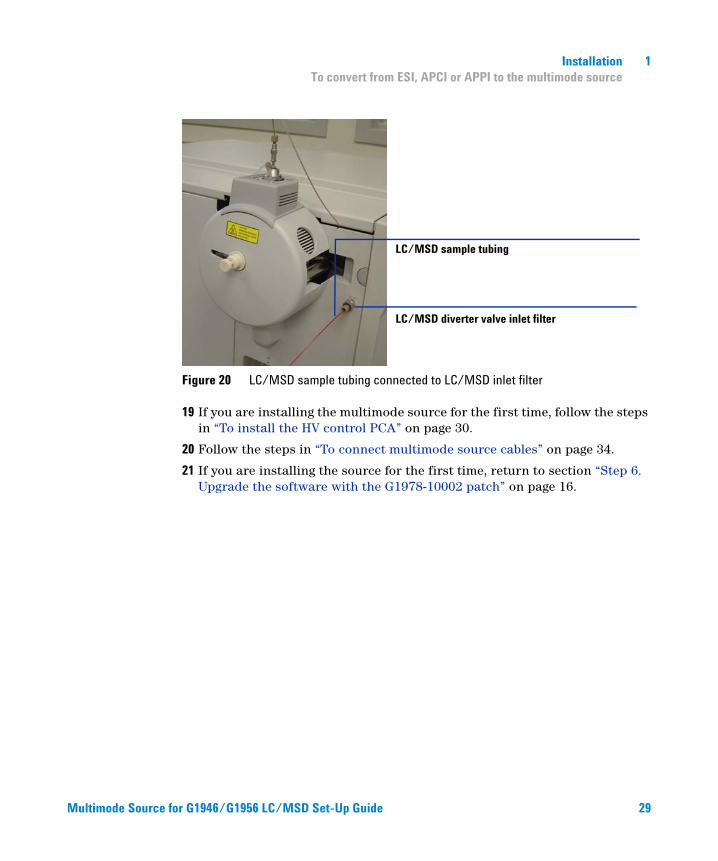
Multimode Source f
Installation 1 To convert from ESI, APCI or APPI to the multimode source
Figure 20 LC/MSD sample tubing connected to LC/MSD inlet filter
19 If you are installing the multimode source for the first time, follow the steps in “To install the HV control PCA” on page 30.
20 Follow the steps in “To connect multimode source cables” on page 34.
21 If you are installing the source for the first time, return to section “Step 6. Upgrade the software with the G1978-10002 patch” on page 16.
LC/MSD diverter valve inlet filter
LC/MSD sample tubing
or G1946/G1956 LC/MSD Set-Up Guide
29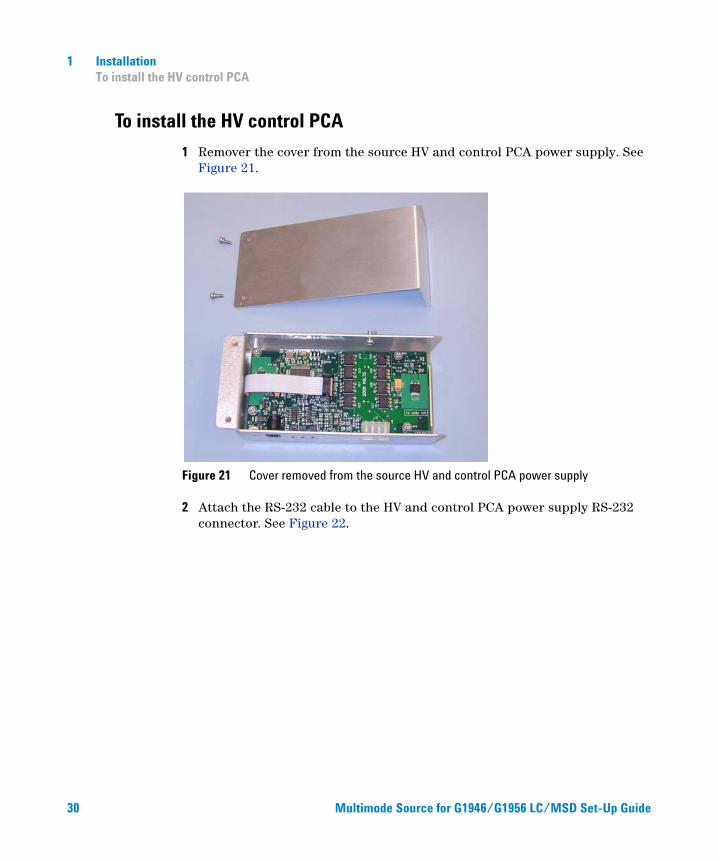
1 Installation To install the HV control PCA
To install the HV control PCA
30
1 Remover the cover from the source HV and control PCA power supply. See Figure 21.
Figure 21 Cover removed from the source HV and control PCA power supply
2 Attach the RS-232 cable to the HV and control PCA power supply RS-232 connector. See Figure 22.
Multimode Source for G1946/G1956 LC/MSD Set-Up Guide
Multimode Source f
Installation 1 To install the HV control PCA
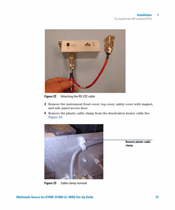
Figure 22 Attaching the RS-232 cable
3 Remove the instrument front cover, top cover, safety cover with magnet, and side panel access door.
4 Remove the plastic cable clamp from the desolvation heater cable See Figure 23.
Figure 23 Cable clamp removal
Remove plastic cable clamp
or G1946/G1956 LC/MSD Set-Up Guide
31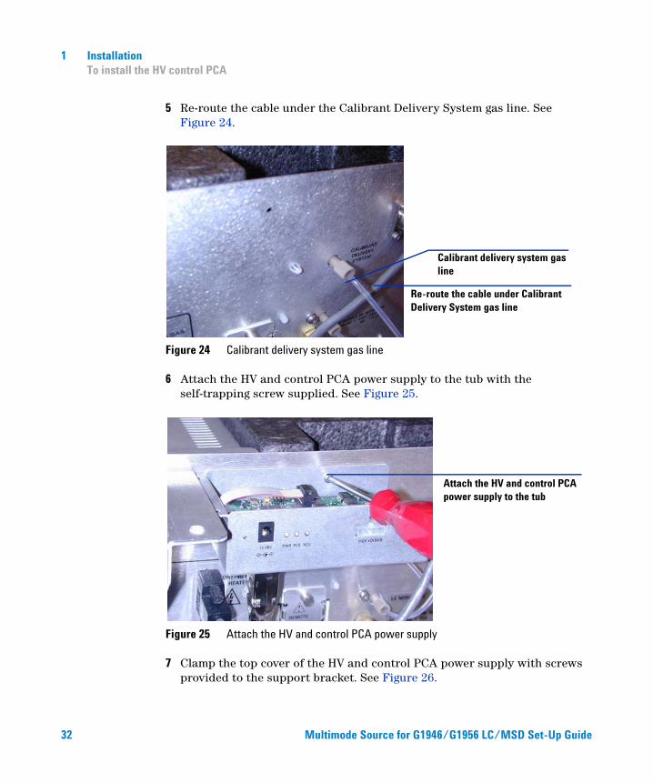
32
1 Installation To install the HV control PCA
5 Re-route the cable under the Calibrant Delivery System gas line. See Figure 24.
Figure 24 Calibrant delivery system gas line
6 Attach the HV and control PCA power supply to the tub with the self-trapping screw supplied. See Figure 25.
Figure 25 Attach the HV and control PCA power supply
7 Clamp the top cover of the HV and control PCA power supply with screws provided to the support bracket. See Figure 26.
Calibrant delivery system gas line
Re-route the cable under Calibrant Delivery System gas line
Attach the HV and control PCA power supply to the tub
Multimode Source for G19
4 6/G1956 LC/MSD Set-Up Guide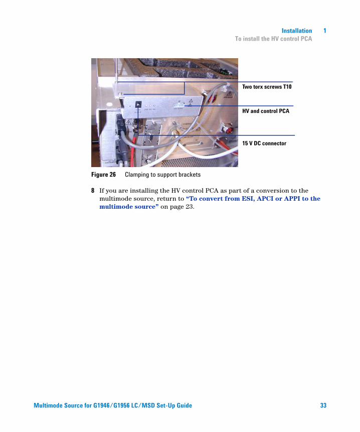
Multimode Source f
Installation 1 To install the HV control PCA
Figure 26 Clamping to support brackets
8 If you are installing the HV control PCA as part of a conversion to the multimode source, return to “To convert from ESI, APCI or APPI to the multimode source” on page 23.
Two torx screws T10
HV and control PCA
15 V DC connector
or G1946/G1956 LC/MSD Set-Up Guide
33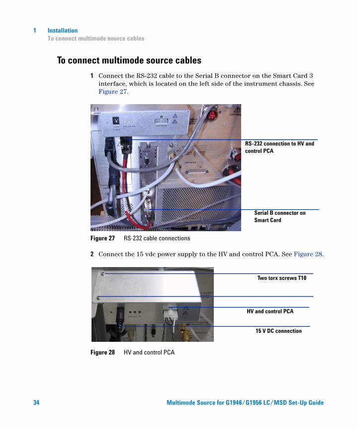
1 Installation To connect multimode source cables
To connect multimode source cables
34
1 Connect the RS-232 cable to the Serial B connector on the Smart Card 3 interface, which is located on the left side of the instrument chassis. See Figure 27.
Figure 27 RS-232 cable connections
2 Connect the 15 vdc power supply to the HV and control PCA. See Figure 28.
Figure 28 HV and control PCA
RS-232 connection to HV and control PCA
Serial B connector on Smart Card
Two torx screws T10
HV and control PCA
15 V DC connection
Multimode Source for G19
46/G 1 956 LC/MSD Set-Up Guide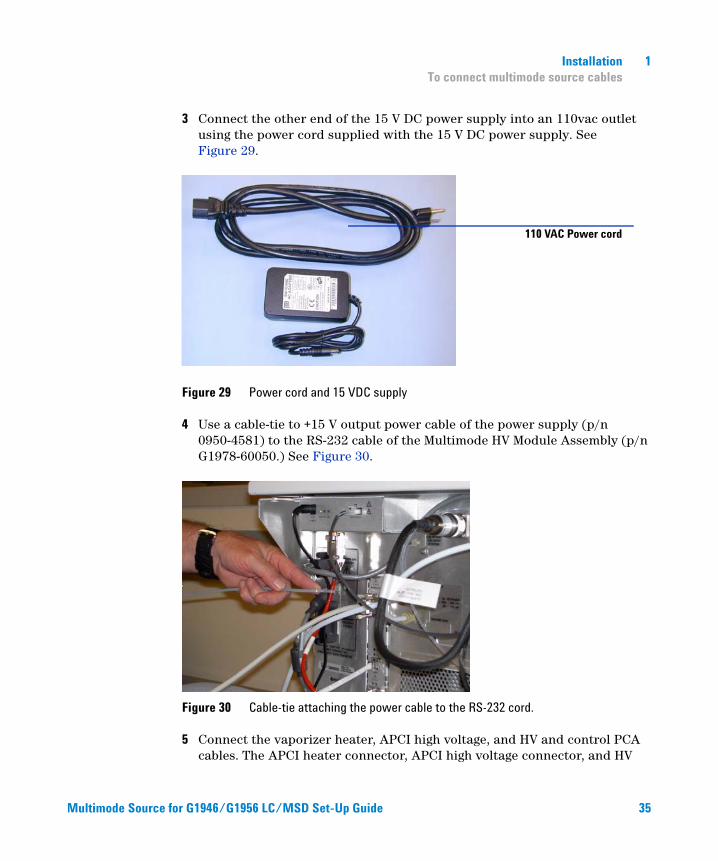
Multimode Source f
Installation 1 To connect multimode source cables
3 Connect the other end of the 15 V DC power supply into an 110vac outlet using the power cord supplied with the 15 V DC power supply. See Figure 29.
Figure 29 Power cord and 15 VDC supply
4 Use a cable-tie to +15 V output power cable of the power supply (p/n 0950-4581) to the RS-232 cable of the Multimode HV Module Assembly (p/n G1978-60050.) See Figure 30.
Figure 30 Cable-tie attaching the power cable to the RS-232 cord.
5 Connect the vaporizer heater, APCI high voltage, and HV and control PCA cables. The APCI heater connector, APCI high voltage connector, and HV
110 VAC Power cord
or G1946/G1956 LC/MSD Set-Up Guide
35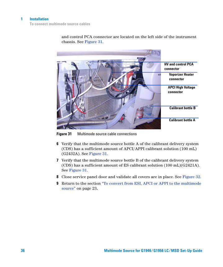
36
1 Installation To connect multimode source cables
and control PCA connector are located on the left side of the instrument chassis. See Figure 31.
Figure 31 Multimode source cable connections
6 Verify that the multimode source bottle A of the calibrant delivery system (CDS) has a sufficient amount of APCI/APPI calibrant solution (100 mL) (G2432A). See Figure 31.
7 Verify that the multimode source bottle B of the calibrant delivery system (CDS) has a sufficient amount of ES calibrant solution (100 mL)(G2421A). See Figure 31.
8 Close service panel door and validate all covers are in place. See Figure 32.
9 Return to the section “To convert from ESI, APCI or APPI to the multimode source” on page 23.
HV and control PCA connector
Vaporizer Heater connector
APCI High Voltage connector
Calibrant bottle B
Calibrant bottle A
Multimode Source for G1946/G195
6 L C/MSD Set-Up Guide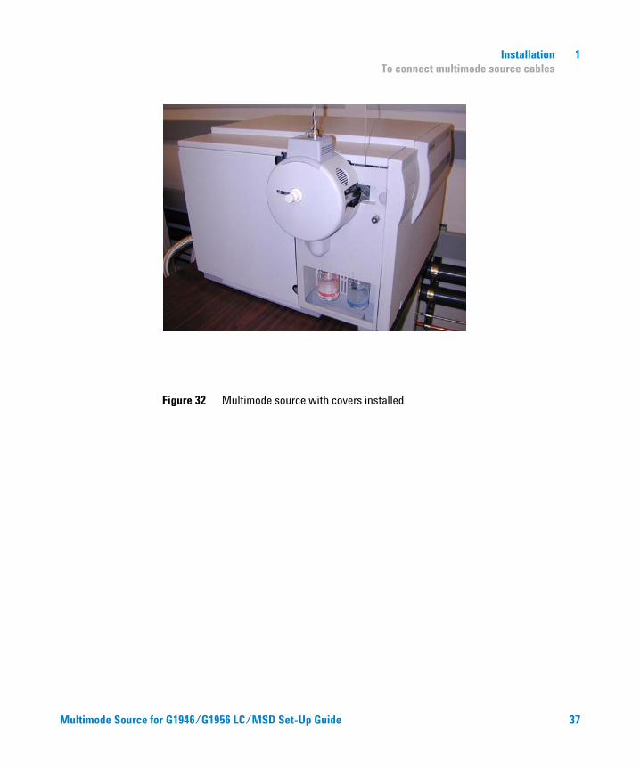
Multimode Source f
Installation 1 To connect multimode source cables
Figure 32 Multimode source with covers installed
or G1946/G1956 LC/MSD Set-Up Guide 37
1 Installation To remove the multimode source
To remove the multimode source
38
Do the following steps to remove the multimode source.
1 The source temperatures for vaporizer heater and drying gas heater need to be set to minimum values to cool the source. Use the Tune > Instrument > Edit Spray Chamber menu item to display the Edit Spray Chamber dialog box. Set the drying gas flow, nebulizer gas flow, drying gas temperature and the vaporizer temperature to minimum values.
WARNING Do not touch the multimode source or the capillary cap. They may be very hot. Let the parts cool before you handle them.
WARNING Never touch the source surfaces, especially when you analyze toxic substances or when you use toxic solvents. The source has several sharp pieces which can pierce your skin including the APCI corona needle, vaporizer sensor and counter current electrode.
WARNING Do not insert fingers or tools through the openings on the multimode chamber. When in use, the capillary and capillary cap are at high voltages up to 4 kV.
2 Wait around 20 minutes until the source is cool.
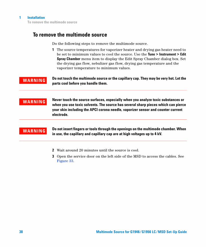
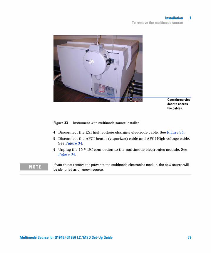
3 Open the service door on the left side of the MSD to access the cables. See Figure 33.
Multimode Source for G1946/G1956 LC/MSD Set-Up Guide
Multimode Source f
Installation 1 To remove the multimode source
Figure 33 Instrument with multimode source installed
4 Disconnect the ESI high voltage charging electrode cable. See Figure 34.
5 Disconnect the APCI heater (vaporizer) cable and APCI High voltage cable. See Figure 34.
6 Unplug the 15 V DC connection to the multimode electronics module. See Figure 34.
Open the service door to access the cables.
NOTE If you do not remove the power to the multimode electronics module, the new source will be identified as unknown source.
or G1946/G1956 LC/MSD Set-Up Guide
39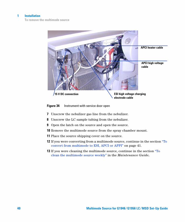
40
1 Installation To remove the multimode source
Figure 34 Instrument with service door open
7 Unscrew the nebulizer gas line from the nebulizer.
8 Unscrew the LC sample tubing from the nebulizer.
9 Open the latch on the source and open the source.
10 Remove the multimode source from the spray chamber mount.
11 Place the source shipping cover on the source.
12 If you were converting from a multimode source, continue in the section “To convert from multimode to ESI, APCI or APPI” on page 41.
13 If you were cleaning the multimode source, continue in the section “To clean the multimode source weekly” in the Maintenance Guide.
ESI high voltage charging electrode cable
APCI heater cable
APCI high voltage cable
15 V DC connection
Multimode Source
for G1946/G1956 L C /MSD Set-Up Guide
Installation 1 To convert from multimode to ESI, APCI or APPI
To convert from multimode to ESI, APCI or APPI
WARNING Do not touch the multimode source or the capillary cap. They may be very hot. Let the parts cool before you handle them.
WARNING Never touch the source surfaces, especially when you analyze toxic substances or when you use toxic solvents. The source has several sharp pieces which can pierce your skin including the APCI corona needle, vaporizer sensor and counter current electrode.
Multimode Source f
1 Do the steps in “To remove the multimode source” on page 38.
2 If the source to be installed is an APPI source, disconnect the multimode high voltage PCA RS-232 serial cable from the serial port B connector of Smart Card.
3 Unscrew and remove the multimode spray shield with the field shaping electrodes.
4 Install the new source and the standard spray shield, making sure that the hole in the spray shield is in the 12 o'clock position.
5 For APCI and APPI ion source, connect the vaporizer heater cable and the APCI high voltage cable. For the APPI source, connect the RS-232 cable to the serial port B connector of Smart Card.
6 For all sources, reconnect the nebulizer gas line tubing and the LC/MSD sample tubing.
or G1946/G1956 LC/MSD Set-Up Guide 41

42
1 Installation To convert from multimode to ESI, APCI or APPI
Multimode Source for G1946/G1956 LC/MSD Set-Up Guide
Agilent G1978A Multimode Source for G1946/G1956 LC/MSDSet-Up Guide
2Verification
To determine proper solvent mixture for performance verification 44
To prepare performance evaluation samples 45
To verify multimode source operations 51
To do an autotune 56
Example of multimode verification report 57
This chapter includes the tasks that you need to do for verification of your multimode source and to validate the proper operation of your source.
43Agilent Technologies
2 Verification To determine proper solvent mixture for performance verification
To determine proper solvent mixture for performance verification
44
Solvent dilutions are given for all supported instruments with multimode source. The reserpine performance verification is only to be done on Bundled G1956A and G1956B instruments shipped with a multimode source.
Use the following information to determine the proper solvent mixture for your instrument model.
G1956A or G1946C LC/MSD VL
Any of the following organic solvents can be used: methanol, isopropanol or acetonitrile.
• 50:50 organic solvent/water
G1956B or G1946B/D LC/MSD SL
• 75:25 methanol/water with 5 mM ammonium formate.
To make the 5mM ammonium formate solution, add 0.315g of ammonium formate to 1 liter of 75:25 methanol/water mobile phase. Use ammonium formate with 97% purity or better.
For both the VL and SL model of the LC/MSD
• Up to 0.2% acetic acid or 0.1% formic acid can be added for positive ion verification. Doing this is usually not necessary, but may be beneficial in overcoming ion suppression resulting from background contaminants in the mobile phase.
• Use solvents of at least HPLC grade. Solvents that are acceptable for most LC applications may contain high levels of background that are detectable by the more sensitive LC/MSD. Make sure LC solvents used with the LC/MSD are rated for both HPLC and pesticide, environmental, or GC/MS analyses. Use the highest purity solvents you can obtain. Acceptability of solvents must be empirically determined.
Multimode Source for G1946/G1956 LC/MSD Set-Up Guide
Verification 2 To prepare performance evaluation samples
To prepare performance evaluation samples
Multimode Source f
This verification method may only be used on a bundled instrument shipped with a
NOTEmultimode source.Before you begin, check that you have:
• 1 mL graduated pipette, p/n 9301-1423
• 50 mL volumetric flask (two each), p/n 9301-1424
• 100 mL volumetric flask, p/n 9301-1344
• Positive ion performance evaluation sample, p/n G2423A (for both interfaces)
• Plastic bottles for storing dilutions, p/n 9301-1433
A bundled instrument will come with the supplies listed above.
The supplied performance evaluation samples must be diluted to concentrations required for the LC/MSD system checkout. Refer to the section “To determine proper solvent mixture for performance verification” for more information.
NOTE Use the diluted samples within a day of dilution. Refrigerate the intermediate (first) dilution in the supplied bottles.
Tips
• Rinse the graduated pipettes and volumetric flasks thoroughly with deionized water before, in between, and after use.
• Use polypropylene labware for preparing performance evaluation samples, since glass vessels introduce unacceptable levels of sodium. Always rinse the autosampler vials and caps with the solvent mix used for sample dilution before filling them with the performance verification samples. Doing this minimizes any background contributed by the vials and caps. The vials may be run uncapped if the septa are found to be a source of background contamination.
or G1946/G1956 LC/MSD Set-Up Guide 45

46
2 Verification To prepare performance evaluation samples
Table 1 G1956A VL Performance Summary SIM, mode
MM-ES PositiveSIM Mode
MM-APCI PositiveSIM Mode
Sample Reserpine, 5 ng/ µL Reserpine, 5 ng/ µL
Concentration after dilution 2 pg/µL 2 pg/µL
Injection volume 5 µL 5 µL
Total sample amount injected 10 pg 10 pg
Sample order number G2423A G2423A
Solvent 50:50organic / water
50:50organic / water
Method name 56VLSMES_MM.M 56VLSMCI_MM.M
Performance specifications 20: 1 pk-pk100: 1 rms
10: 1 pk-pk 50: 1 rms
Table 2 G1956B SL Performance Summary SIM, mode
MM-ES PositiveSIM Mode
MM-APCI PositiveSIM Mode
Sample Reserpine, 5 ng/ µL Reserpine, 5 ng/ µL
Concentration after dilution 1 pg/µL 1 pg/µL
Injection volume 1 µL 1 µL
Total sample amount injected 1 pg 1 pg
Sample order number G2423A G2423A
Solvent 75:25 methanol / waterwith 5mM ammonium formate
75:25 methanol / waterwith 5mMammonium formate
Method name 56SLSMES_MM.M 56SLSMCI_MM.M
Performance specifications 20: 1 pk-pk100: 1 rms
10: 1 pk-pk 50: 1 rms
Multimode Source for G1946/G1956 LC/MSD Set-Up Guide
Multimode Source f
Verification 2 To prepare performance evaluation samples
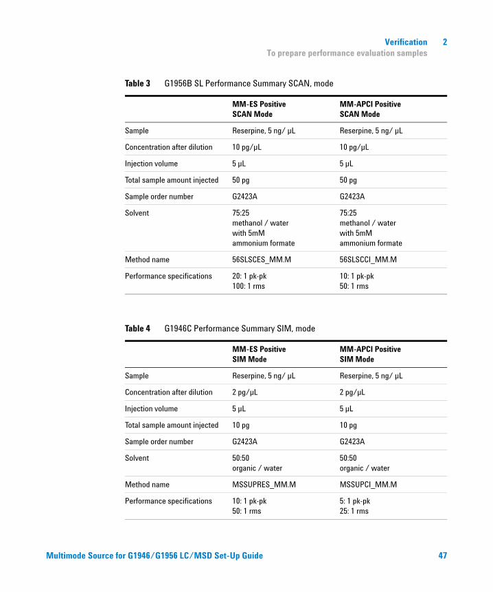
Table 3 G1956B SL Performance Summary SCAN, mode
MM-ES PositiveSCAN Mode
MM-APCI PositiveSCAN Mode
Sample Reserpine, 5 ng/ µL Reserpine, 5 ng/ µL
Concentration after dilution 10 pg/µL 10 pg/µL
Injection volume 5 µL 5 µL
Total sample amount injected 50 pg 50 pg
Sample order number G2423A G2423A
Solvent 75:25 methanol / waterwith 5mM ammonium formate
75:25 methanol / waterwith 5mM ammonium formate
Method name 56SLSCES_MM.M 56SLSCCI_MM.M
Performance specifications 20: 1 pk-pk100: 1 rms
10: 1 pk-pk 50: 1 rms
Table 4 G1946C Performance Summary SIM, mode
MM-ES PositiveSIM Mode
MM-APCI PositiveSIM Mode
Sample Reserpine, 5 ng/ µL Reserpine, 5 ng/ µL
Concentration after dilution 2 pg/µL 2 pg/µL
Injection volume 5 µL 5 µL
Total sample amount injected 10 pg 10 pg
Sample order number G2423A G2423A
Solvent 50:50organic / water
50:50organic / water
Method name MSSUPRES_MM.M MSSUPCI_MM.M
Performance specifications 10: 1 pk-pk 50: 1 rms
5: 1 pk-pk 25: 1 rms
or G1946/G1956 LC/MSD Set-Up Guide 47
48
2 Verification To prepare performance evaluation samples
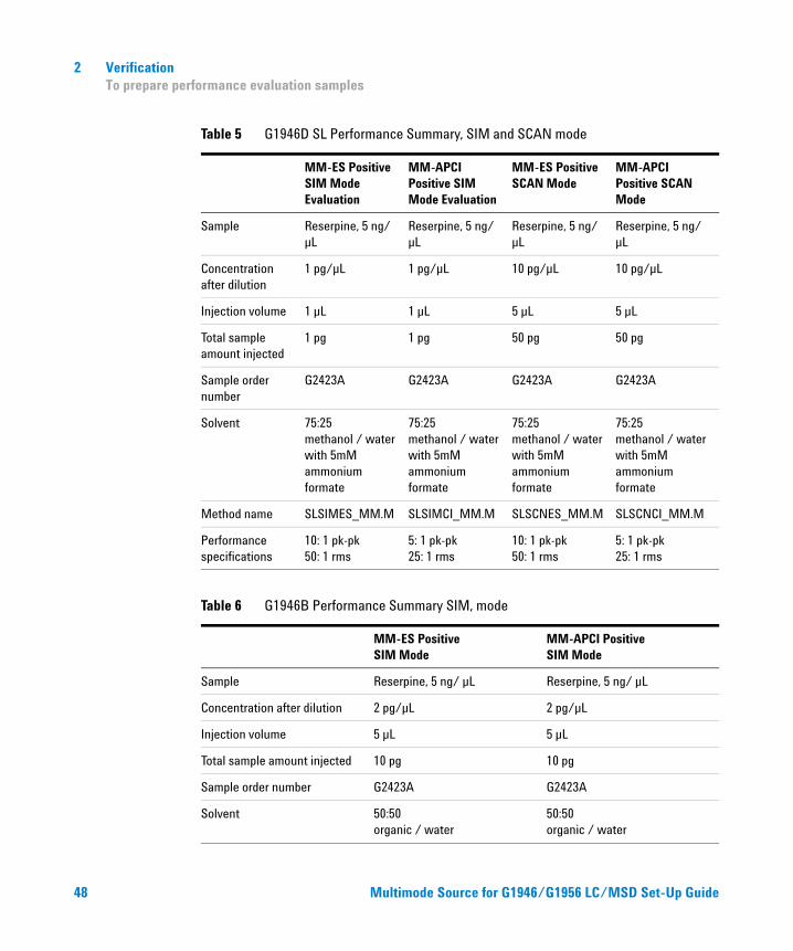
Table 5 G1946D SL Performance Summary, SIM and SCAN mode
MM-ES PositiveSIM Mode Evaluation
MM-APCI Positive SIM Mode Evaluation
MM-ES Positive SCAN Mode
MM-APCI Positive SCAN Mode
Sample Reserpine, 5 ng/ µL
Reserpine, 5 ng/ µL
Reserpine, 5 ng/ µL
Reserpine, 5 ng/ µL
Concentration after dilution
1 pg/µL 1 pg/µL 10 pg/µL 10 pg/µL
Injection volume 1 µL 1 µL 5 µL 5 µL
Total sample amount injected
1 pg 1 pg 50 pg 50 pg
Sample order number
G2423A G2423A G2423A G2423A
Solvent 75:25 methanol / waterwith 5mM ammonium formate
75:25 methanol / waterwith 5mM ammonium formate
75:25 methanol / waterwith 5mM ammonium formate
75:25 methanol / waterwith 5mM ammonium formate
Method name SLSIMES_MM.M SLSIMCI_MM.M SLSCNES_MM.M SLSCNCI_MM.M
Performance specifications
10: 1 pk-pk 50: 1 rms
5: 1 pk-pk 25: 1 rms
10: 1 pk-pk 50: 1 rms
5: 1 pk-pk 25: 1 rms
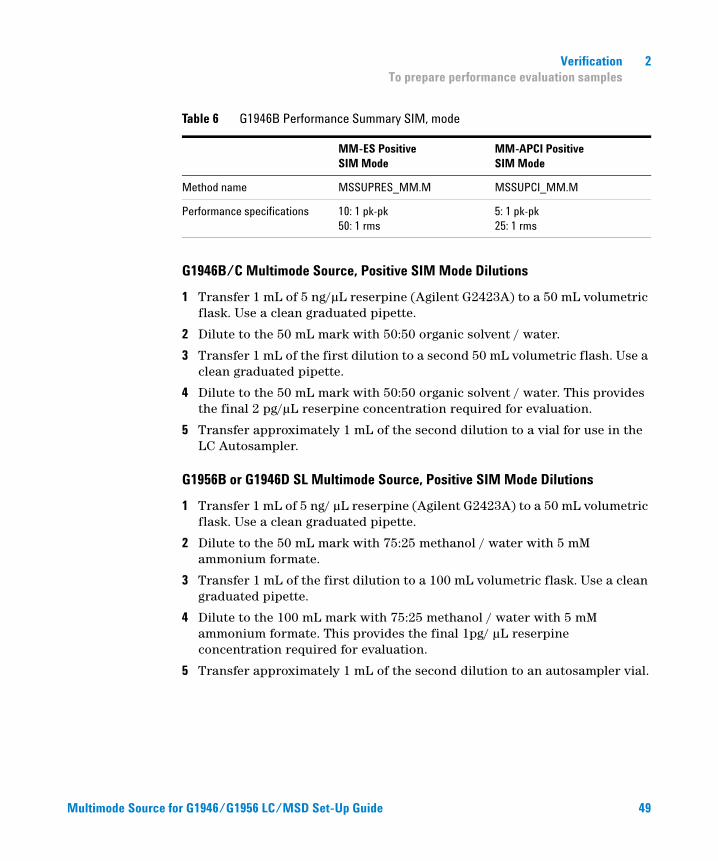
Table 6 G1946B Performance Summary SIM, mode
MM-ES PositiveSIM Mode
MM-APCI PositiveSIM Mode
Sample Reserpine, 5 ng/ µL Reserpine, 5 ng/ µL
Concentration after dilution 2 pg/µL 2 pg/µL
Injection volume 5 µL 5 µL
Total sample amount injected 10 pg 10 pg
Sample order number G2423A G2423A
Solvent 50:50organic / water
50:50organic / water
Multimode Source for G1946/G1956 LC/MSD Set-Up Guide
Multimode Source f
Verification 2 To prepare performance evaluation samples
G1946B/C Multimode Source, Positive SIM Mode Dilutions
1 Transfer 1 mL of 5 ng/µL reserpine (Agilent G2423A) to a 50 mL volumetric flask. Use a clean graduated pipette.
2 Dilute to the 50 mL mark with 50:50 organic solvent / water.
3 Transfer 1 mL of the first dilution to a second 50 mL volumetric flash. Use a clean graduated pipette.
4 Dilute to the 50 mL mark with 50:50 organic solvent / water. This provides the final 2 pg/µL reserpine concentration required for evaluation.
5 Transfer approximately 1 mL of the second dilution to a vial for use in the LC Autosampler.
G1956B or G1946D SL Multimode Source, Positive SIM Mode Dilutions
1 Transfer 1 mL of 5 ng/ µL reserpine (Agilent G2423A) to a 50 mL volumetric flask. Use a clean graduated pipette.
2 Dilute to the 50 mL mark with 75:25 methanol / water with 5 mM ammonium formate.
3 Transfer 1 mL of the first dilution to a 100 mL volumetric flask. Use a clean graduated pipette.
4 Dilute to the 100 mL mark with 75:25 methanol / water with 5 mM ammonium formate. This provides the final 1pg/ µL reserpine concentration required for evaluation.
5 Transfer approximately 1 mL of the second dilution to an autosampler vial.
Method name MSSUPRES_MM.M MSSUPCI_MM.M
Performance specifications 10: 1 pk-pk50: 1 rms
5: 1 pk-pk 25: 1 rms
Table 6 G1946B Performance Summary SIM, mode
MM-ES PositiveSIM Mode
MM-APCI PositiveSIM Mode
or G1946/G1956 LC/MSD Set-Up Guide 49
50
2 Verification To prepare performance evaluation samples
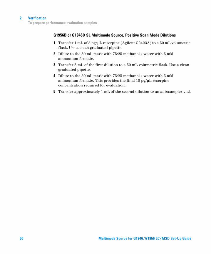
G1956B or G1946D SL Multimode Source, Positive Scan Mode Dilutions
1 Transfer 1 mL of 5 ng/µL reserpine (Agilent G2423A) to a 50 mL volumetric flask. Use a clean graduated pipette.
2 Dilute to the 50 mL mark with 75:25 methanol / water with 5 mM ammonium formate.
3 Transfer 5 mL of the first dilution to a 50 mL volumetric flask. Use a clean graduated pipette.
4 Dilute to the 50 mL mark with 75:25 methanol / water with 5 mM ammonium formate. This provides the final 10 pg/µL reserpine concentration required for evaluation.
5 Transfer approximately 1 mL of the second dilution to an autosampler vial.
Multimode Source for G1946/G1956 LC/MSD Set-Up Guide
Verification 2 To verify multimode source operations
To verify multimode source operations
Multimode Source f
Use the methods specified below to verify the performance of the LC/MSD system for the multimode source purchased with the system. The performance verification methods require an Agilent 1100 LC with an autosampler.
NOTE Check that you have entered the custom tune parameters. Otherwise, you might not be able to tune the LC/MSD.
• G1956A Multimode Source Interface, Positive SIM
• G1956B Multimode Source Interface, Positive Scan
• G1956B Multimode Source Interface, Positive SIM
• G1956B LC/MSD SL model G1978A Interface in Mixed Mode operation
• Multiple FIA model G1978A Interface in Mixed Mode operation
Loading methods for G1956A Multimode Source Interface, Positive SIM
1 Load the method 56VLSMES_MM.M for the G1956A.
2 Edit the method to ensure that 50:50 organic solvent / water is selected as the LC solvent. All other LC parameters correspond to the 56VLSMES_MM.M method parameters.
3 Do an autotune with APCI multimode source calibrant.
NOTE After the autotune has completed, you may need to wait up to 30 minutes before continuing to allow the calibrant solution to be pumped out of the MSD. This minimizes any background signal from the calibrant.
NOTE You may need to further optimize the nebulizer pressure to achieve maximum instrument sensitivity.
4 Place the vials into the LC autosampler.
• Position 1: empty, uncapped vial
• Position 2: vial of the solvent used for dilution (solvent blank)
• Position 3: vial with the reserpine sample (2 pg/µL)
or G1946/G1956 LC/MSD Set-Up Guide 51
52
2 Verification To verify multimode source operations
5 Run the method.
The method performs an FIA run with one injection of the empty vial, five injections of the solvent blank, and five injections of the reserpine sample.
6 Review the results.
When the method is finished, a report prints showing the signal-to-noise ratio for the five blank and five sample peaks, and a blank-subtracted average of the sample peaks. This is to verify operation of the multimode source. The five sample peaks are visible in the EIC.
Loading method for G1956B Multimode Source Interface, Positive Scan
1 Load the method 56SLSCES_MM.M for the G1956B.
2 Edit the method to ensure that 75:25 methanol / water with 5mM ammonium formate is used. All other LC parameters correspond to the 56SLSCES_MM.M method parameters.
3 Do an autotune.
NOTE After the autotune has completed, you may need to wait up to 30 minutes before continuing to allow the calibrant solution to be pumped out of the MSD. This minimizes any background signal from the calibrant.
NOTE You may need to further optimize the nebulizer pressure to achieve maximum instrument sensitivity.
4 Place the vials into the LC autosampler.
• Position 1: empty, uncapped vial
• Position 2: vial of the solvent used for dilution (solvent blank)
• Position 3: vial with the reserpine sample (10 pg/µL)
5 Run the method.
The method performs an FIA run with one injection of the empty vial, five injections of the solvent blank, and five injections of the reserpine sample.
6 Review the results.
Multimode Source for G1946/G1956 LC/MSD Set-Up Guide
Multimode Source f
Verification 2 To verify multimode source operations
When the method is finished, a report prints showing the signal-to-noise ratio for the five blank and five sample peaks, and a blank-subtracted average of the sample peaks. This is to verify operation of the multimode source. The five sample peaks are visible in the EIC.
Loading methods G1956B Multimode Source Interface, Positive SIM
1 Load the method 56SLSM_MM.M for the G1956B.
2 Edit the method to ensure that 75:25 methanol / water with 5mM ammonium formate is selected as the LC solvent.
All other LC parameters correspond to the 56SLSMES_MM.M method parameters.
3 Do an autotune.
NOTE After the autotune has completed, you may need to wait up to 30 minutes before continuing to allow the calibrant solution to be pumped out of the MSD. This minimizes any background signal from the calibrant.
NOTE You may need to further optimize the nebulizer pressure to achieve maximum instrument sensitivity.
4 Place the vials into the LC autosampler.
• Position 1: empty, uncapped vial
• Position 2: vial of the solvent used for dilution (solvent blank)
• Position 3: vial with the reserpine sample (1 pg/µL)
5 Run the method.
The method does an FIA run with one injection of the empty vial, five injections of the solvent blank, and five injections of the reserpine sample.
6 Review the results.
When the method is finished, a report prints showing the signal-to-noise ratio for the five blank and five sample peaks, and a blank-subtracted average of the sample peaks. This is to verify operation of the multimode source. The five sample peaks are visible in the EIC.
or G1946/G1956 LC/MSD Set-Up Guide 53
54
2 Verification To verify multimode source operations
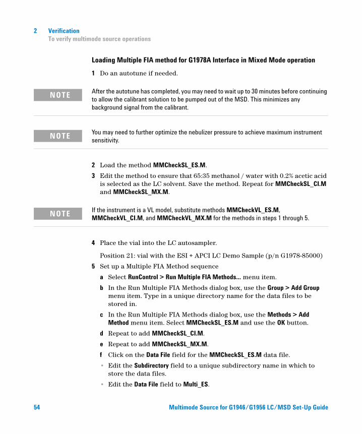
Loading Multiple FIA method for G1978A Interface in Mixed Mode operation
1 Do an autotune if needed.
NOTE After the autotune has completed, you may need to wait up to 30 minutes before continuing to allow the calibrant solution to be pumped out of the MSD. This minimizes any background signal from the calibrant.
NOTE You may need to further optimize the nebulizer pressure to achieve maximum instrument sensitivity.
2 Load the method MMCheckSL_ES.M.
3 Edit the method to ensure that 65:35 methanol / water with 0.2% acetic acid is selected as the LC solvent. Save the method. Repeat for MMCheckSL_CI.M and MMCheckSL_MX.M.
NOTE If the instrument is a VL model, substitute methods MMCheckVL_ES.M, MMCheckVL_CI.M, and MMCheckVL_MX.M for the methods in steps 1 through 5.
4 Place the vial into the LC autosampler.
Position 21: vial with the ESI + APCI LC Demo Sample (p/n G1978-85000)
5 Set up a Multiple FIA Method sequence
a Select RunControl > Run Multiple FIA Methods… menu item.
b In the Run Multiple FIA Methods dialog box, use the Group > Add Group menu item. Type in a unique directory name for the data files to be stored in.
c In the Run Multiple FIA Methods dialog box, use the Methods > Add Method menu item. Select MMCheckSL_ES.M and use the OK button.
d Repeat to add MMCheckSL_CI.M.
e Repeat to add MMCheckSL_MX.M.
f Click on the Data File field for the MMCheckSL_ES.M data file.
• Edit the Subdirectory field to a unique subdirectory name in which to store the data files.
• Edit the Data File field to Multi_ES.
Multimode Source for G1946/G1956 LC/MSD Set-Up Guide
Multimode Source f
Verification 2 To verify multimode source operations
• Edit the Operator field with the users name or identification code.
• Click on the OK button.
g Repeat for the MMCheckSL_CI.M data file, using the same subdirectory as above and entering Multi_CI as the data file name.
h Repeat for the MMCheckSL_MX.M data file, using the same subdirectory as above and entering Multi_MX as the data file name.
i Click on the Run button to start the sequence
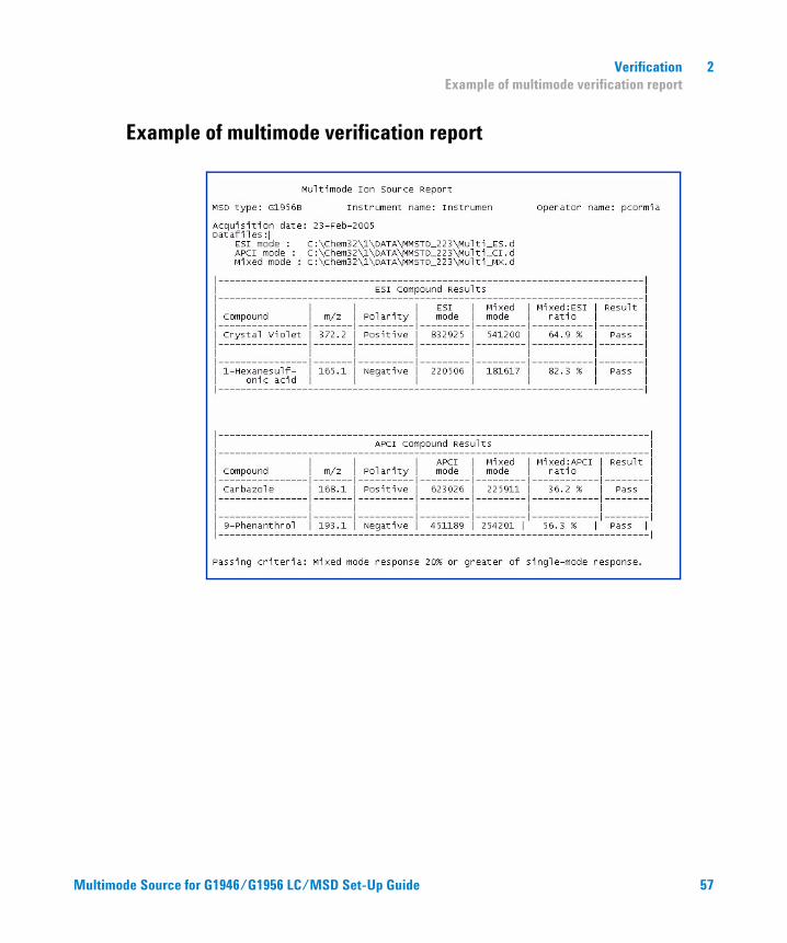
6 Review the results. When the last method has finished, the report “Multimode Verification Report” will print as shown in “Example of multimode verification report” on page 57.
or G1946/G1956 LC/MSD Set-Up Guide 55
2 Verification To do an autotune
To do an autotune
56
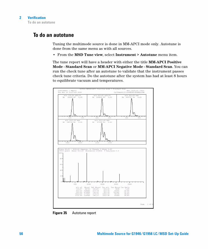
Tuning the multimode source is done in MM-APCI mode only. Autotune is done from the same menu as with all sources.
• From the MSD Tune view, select Instrument > Autotune menu item.
The tune report will have a header with either the title MM-APCI Positive Mode - Standard Scan or MM-APCI Negative Mode - Standard Scan. You can run the check tune after an autotune to validate that the instrument passes check tune criteria. Do the autotune after the system has had at least 8 hours to equilibrate vacuum and temperatures.
Figure 35 Autotune report
Multimode Source for G1946/G1956 LC/MSD Set-Up Guide
Verification 2 Example of multimode verification report
Example of multimode verification report
Multimode Source f
or G1946/G1956 LC/MSD Set-Up Guide 57
58
2 Verification Example of multimode verification report
Multimode Source for G1946/G1956 LC/MSD Set-Up Guide
Agilent G1978A Multimode Source for G1946/G1956 LC/MSDSet-Up Guide
3Methods
To setup a method to use the multimode source 60
To create a method for positive/negative mixed mode operation 61
To create a method for alternating ESI and APCI operation 63
This chapter describes the tasks that you need to set up methods for the multimode source.
59Agilent Technologies
3 Methods To setup a method to use the multimode source
To setup a method to use the multimode source
60
To have your method use a multimode source, follow these steps:
1 Open the MSD Spray Chamber dialog box by clicking Instrument > MSD Spray Chamber in the Method and Run Control view.
2 Set Method Spray Chamber to MM-ES+APCI.
3 Verify that Installed Spray Chamber is set to MM-ES+APCI.
4 Make any other changes that are necessary for your method.
5 Click the OK button.
6 Open The Set up MSD Signals dialog box by clicking Instrument > More > Set up MSD Signals in the Method and Run Control view.
7 Choose the desired ionization mode from the Ionization list. This list is only visible if the Method Spray Chamber was set to MM-ES+APCI. You may set the ionization mode to one of the following:
• MM-ES
• MM-APCI
• MM-ES+APCI
8 Make any other changes that are necessary for your method.
9 Click the OK button.
WARNING The 6100 Series Single Quad LC/MS Liquid Chromatograph diverter valve is an integral part of the G1978B safety system. The LC mobile phase flow must always be connected to the diverter valve inlet filter. Never bypass the diverter valve and connect directly to the nebulizer. If the diverter valve is used in a manner not specified by Agilent Technologies, the protections provided by the diverter valve may be impaired and the system may catch fire.
Multimode Source for G1946/G1956 LC/MSD Set-Up Guide
Methods 3 To create a method for positive/negative mixed mode operation
To create a method for positive/negative mixed mode operation
Multimode Source f
1 Open the MSD Spray Chamber dialog box by clicking the Instrument > Set Up MSD Signals in the Method and Run Control view.
2 Select MM-ES_APCI from the Method Spray Chamber drop-down list.
3 Check that Installed Spray Chamber is also set to MM-ES+APCI.
4 Make any other changes that are necessary for your method.
5 Click the OK button.
6 Open the Set up MSD Signals dialog box by clicking the Instrument > MSD Spray chamber in the Method and Run Control view.
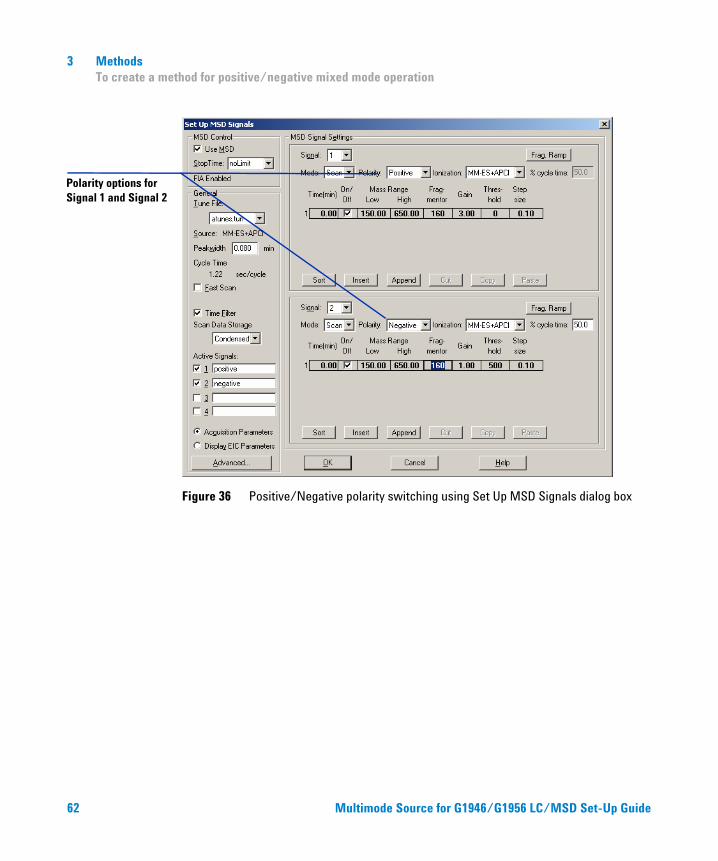
7 Modify the settings so that Signal 1 has Positive polarity and Signal 2 has Negative polarity as shown in Figure 36.
8 Make any other changes that are necessary for your method.
9 Click the OK button.
Fast positive/negative polarity switching is a very useful technique but it requires time for the ion chemistry to be established and the optics path to refill with ions. The gas density plays a role in the speed of refilling the ion path. The gas density is affected by source temperature. For a method running positive/negative switching, use a lower vaporizer temperature (150 to 200°C) and a lower Vcap (approximately 1000 V). These will greatly affect the quality of the results in positive/negative switching experiments.
or G1946/G1956 LC/MSD Set-Up Guide 61
3 Methods To create a method for positive/negative mixed mode operation
Polarity options for Signal 1 and Signal 2
62
Figure 36 Positive/Negative polarity switching using Set Up MSD Signals dialog box
Multimode Source for G1946/G1956 LC/MSD Set-Up Guide
Methods 3 To create a method for alternating ESI and APCI operation
To create a method for alternating ESI and APCI operation
Multimode Source f
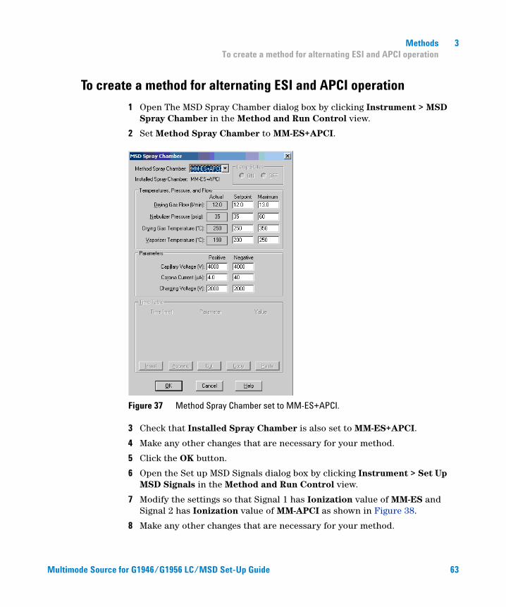
1 Open The MSD Spray Chamber dialog box by clicking Instrument > MSD Spray Chamber in the Method and Run Control view.
2 Set Method Spray Chamber to MM-ES+APCI.
Figure 37 Method Spray Chamber set to MM-ES+APCI.
3 Check that Installed Spray Chamber is also set to MM-ES+APCI.
4 Make any other changes that are necessary for your method.
5 Click the OK button.
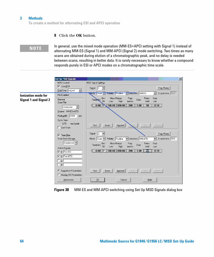
6 Open the Set up MSD Signals dialog box by clicking Instrument > Set Up MSD Signals in the Method and Run Control view.
7 Modify the settings so that Signal 1 has Ionization value of MM-ES and Signal 2 has Ionization value of MM-APCI as shown in Figure 38.
8 Make any other changes that are necessary for your method.
or G1946/G1956 LC/MSD Set-Up Guide 63
64
3 Methods To create a method for alternating ESI and APCI operation
9 Click the OK button.
NOTE In general, use the mixed mode operation (MM-ES+APCI setting with Signal 1) instead of alternating MM-ES (Signal 1) and MM-APCI (Signal 2) mode switching. Two times as many scans are obtained during elution of a chromatographic peak, and no delay is needed between scans, resulting in better data. It is rarely necessary to know whether a compound responds purely in ESI or APCI modes on a chromatographic time scale.
Ionization mode for Signal 1 and Signal 2
Figure 38 MM-ES and MM-APCI switching using Set Up MSD Signals dialog box
Multimode Source for G1946/G1956 LC/MSD Set-Up Guide
Index
Index
Aautotune, 56
Cconverting from ESI, APCI or APPI, 23converting to ESI or APCI, 41
Ddiverter valve inlet filter, 28
EESI
convert from, 23convert to, 41
Iinstallation, 7
change chips, 11check board revisions, 10check boards, 19prepare to, 9switch sources, 16upgrade the software with patch, 16verify performance of the multimode
source, 22
LLC/MSD sample tubing, 29
Mmethod
alternating ESI and APCI, 63basic setup, 60positive/negative mixed mode, 61
multimodenebulizer, 28
Multimode Source for G1946/G1956
Pparts
multimode spray shield, 25prepare performance evaluation
samples, 45
Ssolvent mixture, 44spray shield for multimode source, 25
LC/MSD Set-Up Guide
65
Index
66
Multimode Source for G 1946/G1956 LC/MSD Set-Up Guide
www.agilent.com
In This Book
This book contains installation, operation, maintenance and troubleshooting instruction for the Multimode Source for G1946/G1956 LC/MSD.
© Agilent Technologies, Inc. 2008
Printed in USA First Edition, December 2008
*G1978-90050*G1978-90050
Agilent Technologies