Embed Size (px)
Citation preview

Agilent E8257D PSG Microwave Analog Signal Generator
Data Sheet
The Agilent E8257D is a fully synthesized signal generator with high output power, low phase noise, and optional ramp sweep capability.
Specifications apply over a 0 to 55 °C range, unless otherwise stated, and apply after a 45 minute warm-up time. Supplemental characteristics, denoted as typical, nominal, or measured, provide additional (non-warranted) information at 25 °C, which may be useful in the application of the product.
Unless otherwise noted, this data sheet applies to units with serial numbers ending with 50420000 or greater.
DefinitionsSpecifications (spec): Represents warranted performance for instruments with acurrent calibration.
Typical (typ): Represents characteristic performance which is non-warranted.Describes performance that will be met by a minimum of 80% of all products.
Nominal (nom): Represents characteristic performance which is non-warranted. Represents the value of a parameter that is most likely to occur; the expected meanor mode of all instruments at room temperature (approximately 25 °C).
Measured: Represents characteristic performance which is non-warranted. Represents the value of a parameter measured on an instrument during design verification.

Specifications .............................................................................................. 3 Frequency ........................................................................................................ 3 Step (digital) sweep....................................................................................... 4 Ramp (analog) sweep ................................................................................... 5 Output ..............................................................................................................6 Spectral purity ..............................................................................................12 Frequency modulation .................................................................................21 Phase modulation ........................................................................................22 Amplitude modulation .................................................................................24 External modulation inputs ........................................................................25 Internal modulation source ........................................................................25 Pulse modulation .........................................................................................26 Internal pulse generator .............................................................................28 Simultaneous modulation...........................................................................28 Remote programming ..................................................................................29 General specifications.................................................................................30Input/Output Descriptions ........................................................................ 31 Front panel connectors ...............................................................................31 Rear panel connectors ................................................................................32Options, Accessories, and Related Products ........................................... 33Related Agilent Literature ........................................................................ 35Web Resources .......................................................................................... 35
Table of Contents
2
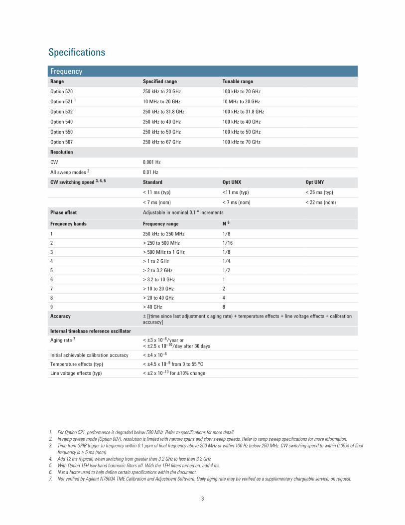
Specifications
1. For Option 521, performance is degraded below 500 MHz. Refer to specifications for more detail.2. In ramp sweep mode (Option 007), resolution is limited with narrow spans and slow sweep speeds. Refer to ramp sweep specifications for more information. 3. Time from GPIB trigger to frequency within 0.1 ppm of final frequency above 250 MHz or within 100 Hz below 250 MHz. CW switching speed to within 0.05% of final
frequency is ≥ 5 ms (nom).4. Add 12 ms (typical) when switching from greater than 3.2 GHz to less than 3.2 GHz.5. With Option 1EH low band harmonic filters off. With the 1EH filters turned on, add 4 ms.6. N is a factor used to help define certain specifications within the document.7. Not verified by Agilent N7800A TME Calibration and Adjustment Software. Daily aging rate may be verified as a supplementary chargeable service, on request.
Frequency bands Frequency range N 6
1 250 kHz to 250 MHz 1/82 > 250 to 500 MHz 1/163 > 500 MHz to 1 GHz 1/84 > 1 to 2 GHz 1/45 > 2 to 3.2 GHz 1/26 > 3.2 to 10 GHz 17 > 10 to 20 GHz 28 > 20 to 40 GHz 49 > 40 GHz 8Accuracy ± [(time since last adjustment x aging rate) + temperature effects + line voltage effects + calibration
accuracy]Internal timebase reference oscillatorAging rate 7 < ±3 x 10⁻⁸/year or
< ±2.5 x 10⁻¹⁰/day after 30 daysInitial achievable calibration accuracy < ±4 x 10⁻⁸
Temperature effects (typ) < ±4.5 x 10⁻⁹ from 0 to 55 °CLine voltage effects (typ) < ±2 x 10⁻¹⁰ for ±10% change
FrequencyRange Specified range Tunable range
Option 520 250 kHz to 20 GHz 100 kHz to 20 GHz
Option 521 1 10 MHz to 20 GHz 10 MHz to 20 GHz
Option 532 250 kHz to 31.8 GHz 100 kHz to 31.8 GHz
Option 540 250 kHz to 40 GHz 100 kHz to 40 GHz
Option 550 250 kHz to 50 GHz 100 kHz to 50 GHz
Option 567 250 kHz to 67 GHz 100 kHz to 70 GHz
Resolution
CW 0.001 Hz
All sweep modes 2 0.01 Hz
CW switching speed 3, 4, 5 Standard Opt UNX Opt UNY
< 11 ms (typ) <11 ms (typ) < 26 ms (typ)
< 7 ms (nom) < 7 ms (nom) < 22 ms (nom)
Phase offset Adjustable in nominal 0.1 ° increments
3

1. To optimize phase noise use 5 dBm ± 2 dB.2. 19 ms (typ) when stepping from greater than 3.2 GHz to less than 3.2 GHz.
External reference
Frequency 10 MHz only
Lock range ±1.0 ppm
Reference output
Frequency 10 MHz
Amplitude > +4 dBm into 50 Ω load (typ)
External reference input
Amplitude 5 dBm ± 5 dB 1
Input impedance 50 Ω (nom)
Step (digital) sweepOperating modes
Step sweep of frequency or amplitude or both (start to stop)
List sweep of frequency or amplitude or both (arbitrary list)
Sweep range
Frequency sweep Within instrument frequency range
Amplitude sweep Within attenuator hold range (see “Output” section)
Dwell time 1 ms to 60 s
Number of points
Step sweep 2 to 65535
List sweep 2 to 1601 per table
Triggering Auto, external, single, or GPIBSettling time Standard Opt UNX Opt UNYFrequency 2 < 9 ms (typ) < 9 ms (typ) < 24 ms (typ)Amplitude < 5 ms (typ) < 5 ms (typ) < 5 ms (typ)
4

Ramp (analog) sweep (Option 007) 1Operating modes
• Synthesized frequency sweep (start/stop), (center/span), (swept CW)• Power (amplitude) sweep (start/stop)• Manual sweep
◦ RPG control between start and stop frequencies • Alternate sweep
◦ Alternates successive sweeps between current and stored statesSweep span range Settable from minimum 2 to full range
Maximum sweep rate Start frequency Maximum sweep rate Max span for 100 ms sweep
250 kHz to < 0.5 GHz 25 MHz/ms 2.5 GHz0.5 to < 1 GHz 50 MHz/ms 5 GHz1 to < 2 GHz 100 MHz/ms 10 GHz2 to < 3.2 GHz 200 MHz/ms 20 GHz≥ 3.2 GHz 400 MHz/ms 40 GHz
Frequency accuracy ± 0.05% of span ± timebase (at 100 ms sweep time, for sweep spans less than maximum values given above) . Accuracy improves proportionally as sweep time increases 3
Sweep time (forward sweep, not including bandswitch and retrace intervals)Manual mode Settable 10 ms to 200 secondsResolution 1 ms
Auto mode Set to minimum value determined by maximum sweep rate and 8757D setting
Triggering Auto, external, single, or GPIB
Markers 10 independent continuously variable frequency markers
Display Z-axis intensity or RF amplitude pulse
Functions M1 to center, M1/M2 to start/stop, marker delta
Two-tone (master/slave) measurements 4 Two PSGs can synchronously track each other, with independent control of start/stop frequencies
Network analyzer compatibility Compatible with Agilent 8757D scalar network analyzer. Also useable with Agilent 8757A/C/E scalar network analyzers for making basic swept measurements. 5
1. During ramp sweep operation, AM, FM, phase modulation, and pulse modulation are useable but performance is not guaranteed. 2. Minimum settable sweep span is proportional to carrier frequency and sweep time. Actual sweep span may be slightly different than desired setting for spans less
than [0.00004% of carrier frequency or 140 Hz] x [sweep time in seconds]. Actual span will always be displayed correctly. 3. Typical accuracy for sweep times > 100 ms can be calculated from the equation: [(0.005% of span)/(sweep time in seconds)] ± timebase. Accuracy is not specified
for sweep times < 100 ms.4. For master/slave operation use Agilent part number 8120-8806 master/slave interface cable.5. GPIB system interface is not supported with 8757A/C/E, only with 8757D. As a result, some features of 8757A/C/E, such as frequency display, pass-through
mode, and alternate sweep, do not function with PSG signal generators.
5
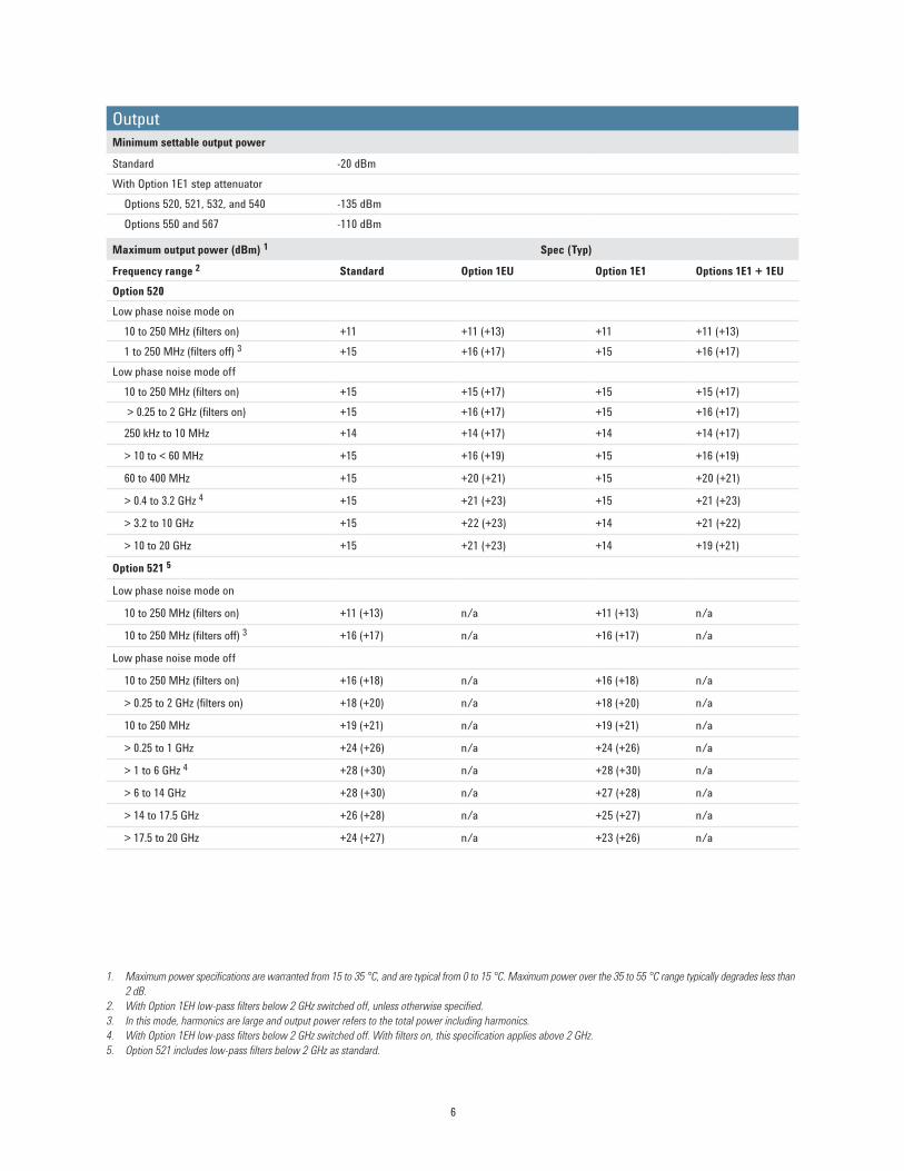
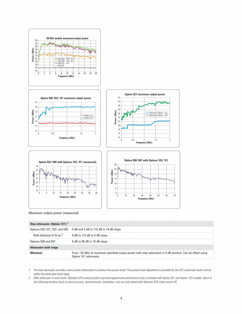
Maximum output power (dBm) 1 Spec (Typ)
Frequency range 2 Standard Option 1EU Option 1E1 Options 1E1 + 1EUOption 520Low phase noise mode on
10 to 250 MHz (filters on) +11 +11 (+13) +11 +11 (+13)1 to 250 MHz (filters off) 3 +15 +16 (+17) +15 +16 (+17)
Low phase noise mode off10 to 250 MHz (filters on) +15 +15 (+17) +15 +15 (+17) > 0.25 to 2 GHz (filters on) +15 +16 (+17) +15 +16 (+17)
250 kHz to 10 MHz +14 +14 (+17) +14 +14 (+17)
> 10 to < 60 MHz +15 +16 (+19) +15 +16 (+19)
60 to 400 MHz +15 +20 (+21) +15 +20 (+21)
> 0.4 to 3.2 GHz 4 +15 +21 (+23) +15 +21 (+23)
> 3.2 to 10 GHz +15 +22 (+23) +14 +21 (+22)
> 10 to 20 GHz +15 +21 (+23) +14 +19 (+21)
Option 521 5
Low phase noise mode on
10 to 250 MHz (filters on) +11 (+13) n/a +11 (+13) n/a
10 to 250 MHz (filters off) 3 +16 (+17) n/a +16 (+17) n/a
Low phase noise mode off
10 to 250 MHz (filters on) +16 (+18) n/a +16 (+18) n/a
> 0.25 to 2 GHz (filters on) +18 (+20) n/a +18 (+20) n/a
10 to 250 MHz +19 (+21) n/a +19 (+21) n/a
> 0.25 to 1 GHz +24 (+26) n/a +24 (+26) n/a
> 1 to 6 GHz 4 +28 (+30) n/a +28 (+30) n/a
> 6 to 14 GHz +28 (+30) n/a +27 (+28) n/a
> 14 to 17.5 GHz +26 (+28) n/a +25 (+27) n/a
> 17.5 to 20 GHz +24 (+27) n/a +23 (+26) n/a
1. Maximum power specifications are warranted from 15 to 35 °C, and are typical from 0 to 15 °C. Maximum power over the 35 to 55 °C range typically degrades less than 2 dB.
2. With Option 1EH low-pass filters below 2 GHz switched off, unless otherwise specified.3. In this mode, harmonics are large and output power refers to the total power including harmonics.4. With Option 1EH low-pass filters below 2 GHz switched off. With filters on, this specification applies above 2 GHz.5. Option 521 includes low-pass filters below 2 GHz as standard.
OutputMinimum settable output power
Standard -20 dBmWith Option 1E1 step attenuator
Options 520, 521, 532, and 540 -135 dBmOptions 550 and 567 -110 dBm
6

Option 532 and 540
Low phase noise mode on
10 to 250 MHz (filters on) +10 +10 (+12) +10 +10 (+12)
1 to 250 MHz (filters off) 1 +11 +15 (+16) +11 +15 (+16)
Low phase noise mode off
10 to 250 MHz (filters on) +11 +14 (+16) +11 +14 (+16)
> 0.25 to 2 GHz (filters on) +11 +15 (+16) +11 +15 (+16)
250 kHz to 10 MHz +11 +13 (+16) +11 +13 (+16)
> 10 to < 60 MHz +11 +15 (+18) +11 +15 (+18)
60 to 400 MHz +11 +19 (+21) +11 +19 (+21)
> 0.4 to 3.2 GHz 2 +11 +20 (+22) +11 +20 (+22)
> 3.2 to 17 GHz +11 +19 (+21) +10 +17 (+20)
> 17 to 37 GHz +11 +16 (+19) +9 +14 (+17)
> 37 to 40 GHz +11 +14 (+17) +9 +12 (+16)
Option 550 and 567
Low phase noise mode on
10 to 250 MHz (filters on) +5 +9 (+11) +5 +9 (+11)
1 to 250 MHz (filters off) 1 +5 +14 (+16) +5 +14 (+16)
Low phase noise mode off
10 to 250 MHz (filters on) +5 +13 (+15) +5 +13 (+15)
> 0.25 to 2 GHz (filters on) +5 +14 (+15) +5 +14 (+15)
250 kHz to 10 MHz +5 +12 (+15) +5 +12 (+15)
> 10 to < 60 MHz +5 +14 (+17) +5 +14 (+17)
60 to 400 MHz +5 +18 (+20) +5 +18 (+20)
> 0.4 to 3.2 GHz 2 +5 +19 (+21) +5 +19 (+21)
> 3.2 to 15 GHz +5 +18 (+21) +4 +17 (+20)
> 15 to 30 GHz +5 +14 (+16) +3 +13 (+15)
> 30 to 65 GHz +5 +11 (+14) +3 +9 (+12)
> 65 to 67 GHz +5 +10 (+14) +3 +8 (+12)
> 67 to 70 GHz (+5) (+8) (+3) (+6)
1. In this mode, harmonics are large and output power refers to the total power including harmonics. 2. With Option 1EH low-pass filters below 2 GHz switched off. With filters on, this specification applies above 2 GHz.
7
14
16
18
20
22
24
26
28
30
32
34
0 0.5 1 1.5 2
Option 521 maximum output power
Harmonic filters - onHarmonic filters - off
Frequency [GHz]
Pow
er [d
Bm]
Option 532/540 with Options 1EU, 1E1 (measured)
16
18
20
22
24
26
28
Frequency [GHz]
Pow
er [d
Bm]
0 5 10 15 20 25 30 35 40
Option 550/567 with Options 1EU, 1E1
0
5
10
15
20
25
30
Frequency [GHz]
Pow
er [d
Bm]
0 10 20 30 40 50 60 70
Step attenuator (Option 1E1) 1
Options 520, 521, 532, and 540 0 dB and 5 dB to 115 dB in 10 dB steps
With Optimize S/N on 2 0 dB to 115 dB in 5 dB steps
Options 550 and 567 0 dB to 90 dB in 10 dB steps
Attenuator hold rangeMinimum From –20 dBm to maximum specified output power with step attenuator in 0 dB position. Can be offset using
Option 1E1 attenuator.
1. The step attenuator provides coarse power attenuation to achieve low power levels. Fine power level adjustment is provided by the ALC (automatic level control) within the attenuator hold range.
2. With attenuator in auto mode. Optimize S/N mode provides improved signal/noise performance and is included with Option 521 and Option 1EU models. Specs in the following sections (such as level accuracy, spectral purity, modulation, etc) are only tested with Optimize S/N mode turned off.
Maximum output power (measured)
20 GHz models maximum output power
1416182022242628303234
Frequency [GHz]
Pow
er [d
Bm]
0 2 4 6 8 10 12 14 16 18 20
Opt 520 - STD, 1E1Opt 520 - 1EU, 1E1Opt 521 - 1E1Opt 521
Option 520-1EU, 1E1 maximum output power
15
17
19
21
23
27
0 0.5 1 1.5 2
25
Filters onFilters off
Frequency [GHz]
Pow
er [d
Bm]
8

1. To within 0.1 dB of final amplitude within one attenuator range. Does not apply to Option 521 below 500 MHz.2. To within 0.5 dB of final amplitude within one attenuator range. Also applies to Option 521 below 500 MHz with ALC on. Add up to 50 ms when using power
search.3. Specifications apply in CW and list/step sweep modes over the 15 to 35 ºC temperature range with the ALC on. Degradation outside this temperature range, for
power levels > -10 dBm is typically < 0.3 dB (except < 0.5 dB from 2 to 3.2 GHz and with Option 521 below 500 MHz). In ramp sweep mode (with Option 007), specifications are typical. For instruments with Type-N connectors (Option 1ED), specifications are degraded typically 0.2 dB above 18 GHz.
4. When Option UNX or UNY low phase noise mode is on, specifications below 250 MHz apply only when Option 1EH low-pass filters below 2 GHz are on. With Option 1EH low-pass filters below 2 GHz off, accuracy is typically ±2 dB.
5. For Option 550 and 567, degrade level accuracy by 0.2 dB from 1.7 to 2 GHz when step attenuator is set to 0 dB or when Option 1E1 is not present.6. Nominal above +16 dBm from 10 MHz to 60 MHz.7. With Option 521, specifications below 500 MHz are typical, and apply for a 50 Ω load with VSWR less than 1.4:1.8. Typical above +26 dBm.9. Typical below -15 dBm. 10. Specifications apply in CW and list/step sweep modes over the 15 to 35 ºC temperature range, with the ALC on and attenuator hold off (normal operating mode).
Degradation outside this temperature range, with attenuator hold on and ALC power levels > -10 dBm, is typically < .3 dB (except < 0.5 dB from 2 to 3.2 GHz and with Option 521 below 500 MHz). In ramp sweep mode (with Option 007), specifications are typical. For instruments with type-N connectors (Option 1ED), specifications apply to 18 GHz only. From 18 to 20 GHz, typical level accuracy degrades by 0.2 dB. Specifications do not apply above the maximum specified power.
11. With Option 521, specifications below 500 MHz apply with step attenuator set to 5 dB or higher (requiring Attenuator Hold ON above 8 dBm). With step attenua-tor set to 0 dB, refer to level accuracy specifications without Option 1E1.
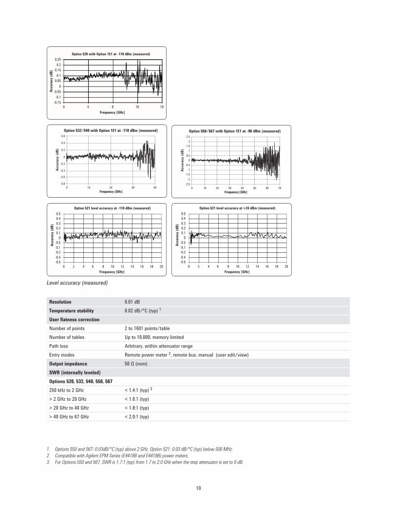
Level accuracy 3 (dB) > 20 dBm 20 to > 16 dBm 16 to > 10 dBm 10 to > 0 dBm 0 to –10 dBm < –10 to –20 dBmOptions 520, 532, 540, 550, 567
250 kHz to 2 GHz 4, 5 ±0.8 ±0.8 6 ±0.6 ±0.6 ±0.6 ±1.2
> 2 to 20 GHz ±1.0 ±0.8 ±0.8 ±0.8 ±0.8 ±1.2
> 20 to 40 GHz ±1.0 ±1.0 ±0.9 ±0.9 ±1.3
> 40 to 50 GHz ±1.3 ±0.9 ±1.2
> 50 to 67 GHz ±1.5 ±1.0 ±1.2 (typ)
Option 52110 to < 500 MHz 4, 7 ±1.9 (typ) ±1.2 (typ) ±1.2 (typ) ±1.1 (typ) ±1.2 (typ) ±1.2 (typ)
0.5 to 20 GHz ±1.0 8 ±0.8 ±0.8 ±0.8 ±0.9 ±1.1 9
Amplitude switching speedALC on < 6 ms (typ) 1
ALC off <10 ms (typ) (not including power search) 2
Level accuracy with step attenuator (Option 1E1) 10 (dB)
26 to > 20 dBm 20 to > 16 dBm 16 to > 10 dBm 10 to > 0 dBm 0 to –10 dBm < –10 to –70 dBm < –70 to –90 dBm
Options 520, 532, 540, 550, 567250 kHz to 2 GHz 4, 5 ±1.0 ±0.8 6 ±0.6 ±0.6 ±0.6 ±0.7 ±0.8
> 2 to 20 GHz ±1.0 ±0.8 ±0.8 ±0.8 ±0.8 ±0.9 ±1.0
> 20 to 40 GHz --- ±1.0 ±1.0 ±0.9 ±0.9 ±1.0 ±2.0
> 40 to 50 GHz --- --- --- ±1.3 ±0.9 ±1.5 ±2.5
> 50 to 67 GHz --- --- --- ±1.5 ±1.0 ±1.5 (typ) ±2.5 (typ)
Option 521
10 to < 500 MHz 4, 11 ±1.3 ±0.8 ±0.8 ±0.7 ±1.0 ±1.0
0.5 to 20 GHz ±1.0 8 ±0.8 ±0.8 ±0.8 ±0.8 ±1.1 ±1.1
9
0.250.2
0.150.1
0.05
-0.05-0.1
-0.15
0
Frequency [GHz]
Option 520 with Option 1E1 at -110 dBm (measured)
0 4 8 16 18
Accu
racy
(dB)
Accu
racy
(dB)
-2
-1-1.5
-0.50
1
21.5
2.5
0.5
-2.50 20 3010 40 50 60 70
Frequency [GHz]
Option 550/567 with Option 1E1 at -90 dBm (measured)
Accu
racy
(dB)
-0.6
-0.4
-0.2
0.2
0.4
0.6
0
-0.80 10 20 30 40
Frequency [GHz]
Option 532/540 with Option 1E1 at -110 dBm (measured)
0.20.30.40.5
0.1
-0.5-0.1
-0.4-0.5
-0.2
0
Accu
racy
(dB)
Option 521 level accuracy at +24 dBm (measured)
0 2 4 6 8 10 12 14 16 18 20Frequency [GHz]
0.20.30.40.5
0.1
-0.5-0.1
-0.4-0.5
-0.2
0
Accu
racy
(dB)
Frequency [GHz]
Option 521 level accuracy at -110 dBm (measured)
0 2 4 6 8 10 12 14 16 18 20
Resolution 0.01 dBTemperature stability 0.02 dB/°C (typ) 1
User flatness correctionNumber of points 2 to 1601 points/tableNumber of tables Up to 10,000, memory limitedPath loss Arbitrary, within attenuator rangeEntry modes Remote power meter 2, remote bus, manual (user edit/view)Output impedance 50 Ω (nom)SWR (internally leveled)Options 520, 532, 540, 550, 567250 kHz to 2 GHz < 1.4:1 (typ) 3
> 2 GHz to 20 GHz < 1.6:1 (typ)> 20 GHz to 40 GHz < 1.8:1 (typ)> 40 GHz to 67 GHz < 2.0:1 (typ)
Level accuracy (measured)
1. Options 550 and 567: 0.03dB/°C (typ) above 2 GHz. Option 521: 0.03 dB/°C (typ) below 500 MHz. 2. Compatible with Agilent EPM Series (E4418B and E4419B) power meters.3. For Options 550 and 567, SWR is 1.7:1 (typ) from 1.7 to 2.0 GHz when the step attenuator is set to 0 dB.
10
1. For Option 521, maximum reverse power is 1/2 watt when Option 1E1 step attenuator is set at or above 5 dB. When Option 1E1 step attenuator = 0 dB, or for units without Option 1E1, maximum reverse power is 2 watts above 250 MHz, 1/2 watt below 250 MHz.
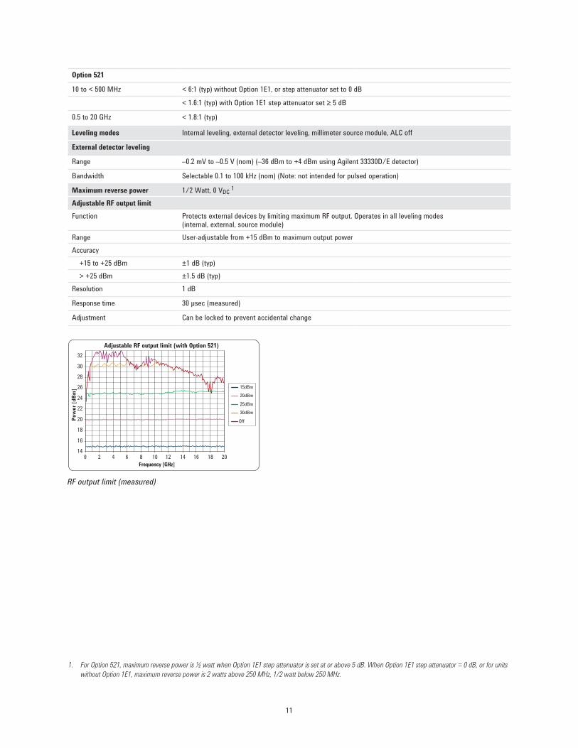
Adjustable RF output limit (with Option 521)
140 2 4 6 8 10 12 14 16 18 20
16
18
20
22
24
26
28
30
32
Frequency [GHz]
Pow
er [d
Bm] 15dBm
20dBm
25dBm 30dBm
Off
Leveling modes Internal leveling, external detector leveling, millimeter source module, ALC off
External detector leveling
Range –0.2 mV to –0.5 V (nom) (–36 dBm to +4 dBm using Agilent 33330D/E detector)
Bandwidth Selectable 0.1 to 100 kHz (nom) (Note: not intended for pulsed operation)
Maximum reverse power 1/2 Watt, 0 VDC 1
Adjustable RF output limitFunction Protects external devices by limiting maximum RF output. Operates in all leveling modes
(internal, external, source module)Range User-adjustable from +15 dBm to maximum output powerAccuracy
+15 to +25 dBm ±1 dB (typ)> +25 dBm ±1.5 dB (typ)
Resolution 1 dB
Response time 30 μsec (measured)
Adjustment Can be locked to prevent accidental change
Option 521
10 to < 500 MHz < 6:1 (typ) without Option 1E1, or step attenuator set to 0 dB
< 1.6:1 (typ) with Option 1E1 step attenuator set ≥ 5 dB
0.5 to 20 GHz < 1.8:1 (typ)
RF output limit (measured)
11

Spectral purityHarmonics 1 (dBc at +10 dBm or maximum specified output power, whichever is lower)Frequency Options 520, 532, 540, 550, 567 Option 521< 1 MHz -25 dBc (typ)1 to < 10 MHz -25 dBc10 to < 60 MHz -28 dBc -25 dBc
10 to < 60 MHz with Option 1EH filters on -45 dBc 2 -35 dBc 2, 3
0.06 to 2 GHz -30 dBc -25 dBc
0.06 to 2 GHz with Option 1EH filters on -55 dBc 2 -35 dBc 2, 3
> 2 to 20 GHz -55 dBc -35 dBc> 20 to 67 GHz -50 dBc (typ)
1. Specifications are typical for harmonics beyond specified frequency range (beyond 50 GHz for Option 567). Specifications are with Option 1EH Low-pass Filters below 2 GHz off and Option UNX or UNY low phase noise mode off unless noted.
2. Below 250 MHz in ramp sweep mode (Option 007), Option 1EH filters are always off. Refer to harmonic specification with filters off.3. Option 521 includes low-pass filters below 2 GHz as standard.4. -45 dBc below 60 MHz.
10 to 250 MHz, Option UNX or UNY low phase noise mode
With Option 1EH filters off -8 dBc (typ) -8 dBc (typ)
With Option 1EH filters on -55 dBc 4 -35 dBc
12
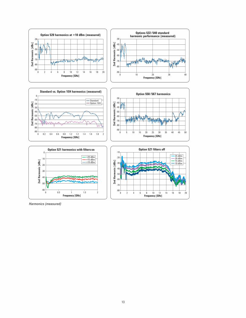
Option 520 harmonics at +10 dBm (measured)
-900 2 4 6 8 10 12 14 16 18 20
-80
-70
-60
-50
-40
-30
Frequency [GHz]
2nd
Harm
onic
[dBc
]Options 532/540 standard
harmonic performance (measured)
-900 10 20 30 40
-80
-70
-60
-50
-40
-30
Frequency [GHz]
2nd
Harm
onic
[dBc
]
Standard vs. Option 1EH harmonics (measured)
-900 0.40.2 1.20.6 0.8 1.41.2 1.6 1.8 2
-80
-40-30-20-10
0
Frequency [GHz]
2nd
Harm
onic
[dBc
]
-50-60-70
StandardOption 1EH
Option 550/567 harmonics
-900 5 10 15 20 25 30 35 40 45 50
-80
-70
-60
-50
-40
-30
Frequency [GHz]
2nd
Harm
onic
[dBc
] -40
-800 2 4 6 8 10 12 14 16 18 20
-40
-30
-10
-20
-50
-60
-70
Option 521 filters off
25 dBm20 dBm15 dBm10 dBm
Frequency [GHz]
2nd
Harm
onic
[dBc
]
Harmonics (measured)
-600 0.5 1 1.5 2
-50
-40
-30
-20
0
-10
Option 521 harmonics with filters On
+20 dBm+15 dBm+10 dBm
Frequency [GHz]
2nd
Harm
onic
[dBc
]
on
13
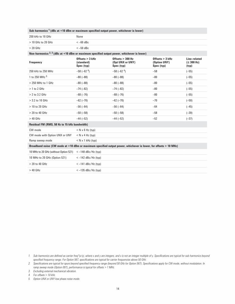
Sub-harmonics 1 (dBc at +10 dBm or maximum specified output power, whichever is lower)
250 kHz to 10 GHz None
> 10 GHz to 20 GHz < –60 dBc
> 20 GHz < –50 dBc
Non-harmonics 2, 3 (dBc at +10 dBm or maximum specified output power, whichever is lower)
FrequencyOffsets > 3 kHz (standard) Spec (typ)
Offsets > 300 Hz (Opt UNX or UNY) Spec (typ)
Offsets > 3 kHz (Option UNY) Spec (typ)
Line-related (≤ 300 Hz) (typ)
250 kHz to 250 MHz –58 (–62 4) –58 (–62 4) –58 (–55)
1 to 250 MHz 5 –80 (–88) –80 (–88) –80 (–55)
> 250 MHz to 1 GHz –80 (–88) –80 (–88) –80 (–55)
> 1 to 2 GHz –74 (–82) –74 (–82) –80 (–55)
> 2 to 3.2 GHz –68 (–76) –68 (–76) –80 (–55)
> 3.2 to 10 GHz –62 (–70) –62 (–70) –70 (–50)
> 10 to 20 GHz –56 (–64) –56 (–64) –64 (–45)
> 20 to 40 GHz –50 (–58) –50 (–58) –58 (–39)
> 40 GHz –44 (–52) –44 (–52) –52 (–37)
Residual FM (RMS, 50 Hz to 15 kHz bandwidth)
CW mode < N x 6 Hz (typ)CW mode with Option UNX or UNY < N x 4 Hz (typ)Ramp sweep mode < N x 1 kHz (typ)
Broadband noise (CW mode at +10 dBm or maximum specified output power, whichever is lower, for offsets > 10 MHz)
10 MHz to 20 GHz (without Option 521) < –148 dBc/Hz (typ)
10 MHz to 20 GHz (Option 521) < –142 dBc/Hz (typ)
> 20 to 40 GHz < –141 dBc/Hz (typ)
> 40 GHz < –135 dBc/Hz (typ)
1. Sub-harmonics are defined as carrier freq*(x/y), where x and y are integers, and x is not an integer multiple of y. Specifications are typical for sub-harmonics beyond specified frequency range. For Option 567, specifications are typical for carrier frequencies above 50 GHz.
2. Specifications are typical for spurs beyond specified frequency range (beyond 50 GHz for Option 567). Specifications apply for CW mode, without modulation. In ramp sweep mode (Option 007), performance is typical for offsets > 1 MHz.
3. Excluding external mechanical vibration.4. For offsets > 10 kHz. 5. Option UNX or UNY low phase noise mode.
14
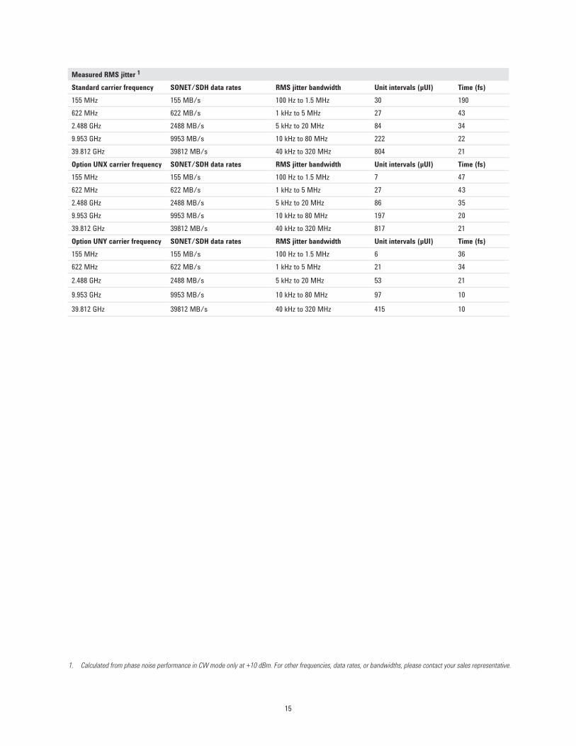
Measured RMS jitter 1
Standard carrier frequency SONET/SDH data rates RMS jitter bandwidth Unit intervals (μUI) Time (fs)155 MHz 155 MB/s 100 Hz to 1.5 MHz 30 190622 MHz 622 MB/s 1 kHz to 5 MHz 27 432.488 GHz 2488 MB/s 5 kHz to 20 MHz 84 349.953 GHz 9953 MB/s 10 kHz to 80 MHz 222 2239.812 GHz 39812 MB/s 40 kHz to 320 MHz 804 21Option UNX carrier frequency SONET/SDH data rates RMS jitter bandwidth Unit intervals (μUI) Time (fs)155 MHz 155 MB/s 100 Hz to 1.5 MHz 7 47622 MHz 622 MB/s 1 kHz to 5 MHz 27 432.488 GHz 2488 MB/s 5 kHz to 20 MHz 86 359.953 GHz 9953 MB/s 10 kHz to 80 MHz 197 2039.812 GHz 39812 MB/s 40 kHz to 320 MHz 817 21Option UNY carrier frequency SONET/SDH data rates RMS jitter bandwidth Unit intervals (μUI) Time (fs)155 MHz 155 MB/s 100 Hz to 1.5 MHz 6 36622 MHz 622 MB/s 1 kHz to 5 MHz 21 34
2.488 GHz 2488 MB/s 5 kHz to 20 MHz 53 21
9.953 GHz 9953 MB/s 10 kHz to 80 MHz 97 10
39.812 GHz 39812 MB/s 40 kHz to 320 MHz 415 10
1. Calculated from phase noise performance in CW mode only at +10 dBm. For other frequencies, data rates, or bandwidths, please contact your sales representative.
15
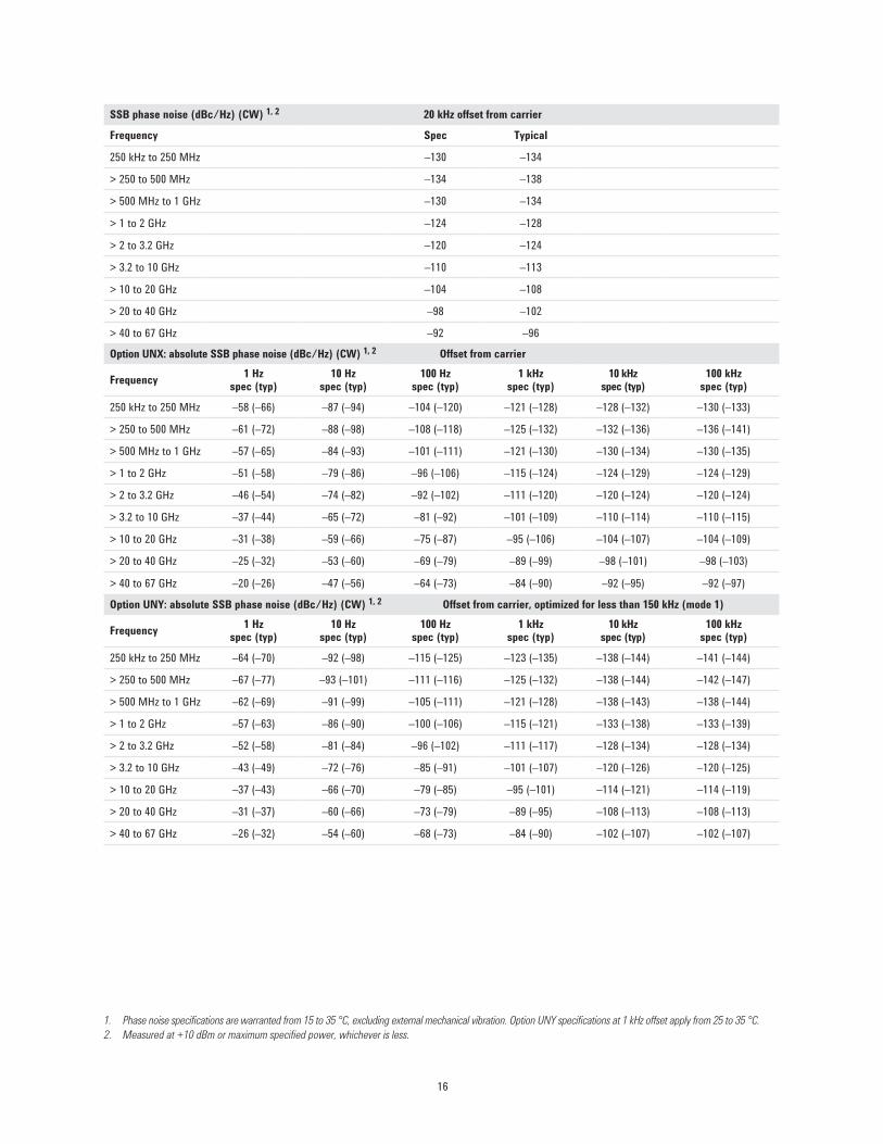
1. Phase noise specifications are warranted from 15 to 35 °C, excluding external mechanical vibration. Option UNY specifications at 1 kHz offset apply from 25 to 35 °C.2. Measured at +10 dBm or maximum specified power, whichever is less.
SSB phase noise (dBc/Hz) (CW) 1, 2 20 kHz offset from carrier
Frequency Spec Typical
250 kHz to 250 MHz –130 –134
> 250 to 500 MHz –134 –138
> 500 MHz to 1 GHz –130 –134
> 1 to 2 GHz –124 –128
> 2 to 3.2 GHz –120 –124
> 3.2 to 10 GHz –110 –113
> 10 to 20 GHz –104 –108
> 20 to 40 GHz –98 –102
> 40 to 67 GHz –92 –96
Option UNX: absolute SSB phase noise (dBc/Hz) (CW) 1, 2 Offset from carrier
Frequency 1 Hz spec (typ)
10 Hz spec (typ)
100 Hz spec (typ)
1 kHz spec (typ)
10 kHz spec (typ)
100 kHz spec (typ)
250 kHz to 250 MHz –58 (–66) –87 (–94) –104 (–120) –121 (–128) –128 (–132) –130 (–133)
> 250 to 500 MHz –61 (–72) –88 (–98) –108 (–118) –125 (–132) –132 (–136) –136 (–141)
> 500 MHz to 1 GHz –57 (–65) –84 (–93) –101 (–111) –121 (–130) –130 (–134) –130 (–135)
> 1 to 2 GHz –51 (–58) –79 (–86) –96 (–106) –115 (–124) –124 (–129) –124 (–129)
> 2 to 3.2 GHz –46 (–54) –74 (–82) –92 (–102) –111 (–120) –120 (–124) –120 (–124)
> 3.2 to 10 GHz –37 (–44) –65 (–72) –81 (–92) –101 (–109) –110 (–114) –110 (–115)
> 10 to 20 GHz –31 (–38) –59 (–66) –75 (–87) –95 (–106) –104 (–107) –104 (–109)
> 20 to 40 GHz –25 (–32) –53 (–60) –69 (–79) –89 (–99) –98 (–101) –98 (–103)
> 40 to 67 GHz –20 (–26) –47 (–56) –64 (–73) –84 (–90) –92 (–95) –92 (–97)
Option UNY: absolute SSB phase noise (dBc/Hz) (CW) 1, 2 Offset from carrier, optimized for less than 150 kHz (mode 1)
Frequency 1 Hz spec (typ)
10 Hz spec (typ)
100 Hz spec (typ)
1 kHz spec (typ)
10 kHz spec (typ)
100 kHz spec (typ)
250 kHz to 250 MHz –64 (–70) –92 (–98) –115 (–125) –123 (–135) –138 (–144) –141 (–144)
> 250 to 500 MHz –67 (–77) –93 (–101) –111 (–116) –125 (–132) –138 (–144) –142 (–147)
> 500 MHz to 1 GHz –62 (–69) –91 (–99) –105 (–111) –121 (–128) –138 (–143) –138 (–144)
> 1 to 2 GHz –57 (–63) –86 (–90) –100 (–106) –115 (–121) –133 (–138) –133 (–139)
> 2 to 3.2 GHz –52 (–58) –81 (–84) –96 (–102) –111 (–117) –128 (–134) –128 (–134)
> 3.2 to 10 GHz –43 (–49) –72 (–76) –85 (–91) –101 (–107) –120 (–126) –120 (–125)
> 10 to 20 GHz –37 (–43) –66 (–70) –79 (–85) –95 (–101) –114 (–121) –114 (–119)
> 20 to 40 GHz –31 (–37) –60 (–66) –73 (–79) –89 (–95) –108 (–113) –108 (–113)
> 40 to 67 GHz –26 (–32) –54 (–60) –68 (–73) –84 (–90) –102 (–107) –102 (–107)
16

1. Phase noise specifications are warranted from 15 to 35 °C, excluding external mechanical vibration. Option UNY specifications at 1 kHz offset apply from 25 to 35 °C.2. Measured at +10 dBm or maximum specified power, whichever is less.3. Measured with filters off at +16 dBm or maximum achievable leveled power, whichever is less. Without Option 1EU, frequencies of 10 MHz and below are not
specified. Without Option 1EU or 521, offsets of 10 kHz and greater are not specified.
Option UNX: residual SSB phase noise (dBc/Hz) (CW) 1, 2 Offset from carrier
Frequency 1 Hz spec (typ)
10 Hz spec (typ)
100 Hz spec (typ)
1 kHz spec (typ)
10 kHz spec (typ)
100 kHz spec (typ)
250 kHz to 250 MHz (–94) –100 (–107) –110 (–118) –120 (–126) –128 (–132) –130 (–133)> 250 to 500 MHz (–101) –105 (–112) –115 (–122) –124 (–131) –132 (–136) –136 (–141)> 500 MHz to 1 GHz (–94) –100 (–107) –110 (–118) –120 (–126) –130 (–134) –130 (–134)> 1 to 2 GHz (–89) –96 (–101) –104 (–112) –114 (–120) –124 (–129) –124 (–129)> 2 to 3.2 GHz (–85) –92 (–97) –100 (–108) –110 (–116) –120 (–124) –120 (–124)> 3.2 to 10 GHz (–74) (–87) (–98) (–106) (–114) (–115)Option UNY: residual SSB phase noise (dBc/Hz) (CW) 1, 2 Offset from carrier, optimized for less than 150 kHz (mode 1)
Frequency 1 Hz spec (typ)
10 Hz spec (typ)
100 Hz spec (typ)
1 kHz spec (typ)
10 kHz spec (typ)
100 kHz spec (typ)
250 kHz to 250 MHz (–94) –100(–107) –110 (–118) –123 (–135) –138 (–144) –141 (–144)> 250 to 500 MHz (–101) –105 (–112) –115 (–122) –124 (–130) –138 (–144) –140 (–147)> 500 MHz to 1 GHz (–94) –100 (–108) –110 (–118) –120 (–126) –135 (–142) –135 (–145)> 1 to 2 GHz (–89) –96 (–101) –104 (–112) –115 (–121) –133 (–138) –133 (–139)> 2 to 3.2 GHz (–85) –92 (–97) –100 (–108) –111 (–117) –128 (–134) –128 (–134)> 3.2 to 10 GHz (–74) (–87) (–98) (–104) (–126) (–125)Option UNX: absolute SSB phase noise (dBc/Hz) (CW)Low phase noise mode (1 to 250 MHz) 1, 3 Offset from carrier
Frequency 1 Hz spec (typ)
10 Hz spec (typ)
100 Hz spec (typ)
1 kHz spec (typ)
10 kHz spec (typ)
100 kHz spec (typ)
1 MHz (–109) (–120) (–130) (–143) (–150) (–150)10 MHz –90 (–95) –125 (–130) –130 (–135) –143 (–148) –155 (–158) –155 (–158)10 MHz (Option 521) (–95) (–115) (–125) (–138) (–145) (–145)100 MHz –70 (–75) –97 (–102) –119 (–124) –130 (–135) –140 (–145) –140 (–145)250 MHz (–76) (–104) (–121) (–138) (–142) (–142)Option UNY: absolute SSB phase noise (dBc/Hz) (CW)Low phase noise mode (1 to 250 MHz) 1, 3 Offset from carrier, optimized for less than 150 kHz (mode 1)
Frequency 1 Hz spec (typ)
10 Hz spec (typ)
100 Hz spec (typ)
1 kHz spec (typ)
10 kHz spec (typ)
100 kHz spec (typ)
1 MHz –116 (–129) –140 (–151) –153 (–161) –160 (–166) –160 (–167) –160 (–165)10 MHz –96 (–111) –126 (–133) –140 (–150) –155 (–162) –155 (–165) –155 (–165)10 MHz (Option 521) (–100) (–120) (–135) (–145) (–150) (–150)100 MHz –80 (–96) –105 (–120) –120 (–130) –138 (–146) –150 (–157) –150 (–157)100 MHz (Option 521) –80 (–92) –105 (–110) –120 (–125) –138 (–145) –150 (–152) –150 (–152)250 MHz –68 (–77) –100 (–108) –114 (–122) –133 (–139) –144 (–153) –144 (–154)250 MHz (Option 521 –68 (–77) –100 (–105) –114 (–118) –133 (–139) –144 (–152) –144 (–152)
17

Standard SSB phase noise-20-30-40-50-60-70-80-90
-100-110-120-130-140-150-160-170
L(f) (dBc/Hz) vs. f (Hz) 10 100 1 k 10 k 100 k 1 M 10 M 100 M
zHG 7640 GHz20 GHz10 GHz1 GHz
Absolute SSB phase noise at 10 GHz-40-50-60-70-80-90
-100-110-120-130-140-150-160-170
L(f) (dBc/Hz) vs. f (Hz) 1 10 100 1 k 10 k 100 k 1 M 10 M 100M
Opt UNY mode 1Opt UNY mode 2Opt UNXStandard
Option UNX residual phase noise-20-30-40-50-60-70-80-90
-100-110-120-130-140-150-160-170
L(f) (dBc/Hz) vs. f (Hz)1 10 100 1 k 10 k 100 k 1 M 10 M 100 M
10 GHz3 GHz1 GHz
Option UNX absolute SSB phase noiselow phase noise mode
-20-30-40-50-60-70-80-90
-100-110-120-130-140-150-160-170
L(f) (dBc/Hz) vs. f (Hz)1 10 100 1 k 10 k 100 k 1 M 10 M 100 M
10 MHz100 MHz
L(f) (dBc/Hz) vs. f (Hz)
Option UNX residual phase noise low phase noise mode
-20-30-40-50-60-70-80-90
-100-110-120-130-140-150-160-170
1 10 100 1 k 10 k 100 k 1 M 10 M 100 M
10 MHz100 MHz
Option UNX absolute SSB phase noise-20-30-40-50-60-70-80-90
-100-110-120-130-140-150-160-170
L(f) (dBc/Hz) vs. f (Hz)1 10 100 1 k 10 k 100 k 1 M 10 M 100 M
zHG 76 40 GHz20 GHz10 GHz1 GHz
Measured phase noise (data collected with the E5500 and plotted without spurs)
Absolute SSB phase noise at 10 GHzStandard SSB phase noise
Option UNX absolute SSB phase noise Option UNX absolute SSB phase noise low phase noise mode
Option UNX residual phase noiselow phase noise modeOption UNX residual phase noise
18
L(f) (dBc/Hz) vs. f (Hz)
STD measured AM noise at 10 GHz-20-30-40-50-60-70-80-90
-100-110-120-130-140-150-160-170
1 10 100 1 k 10 k 100 k 1 M 10 M 100 M
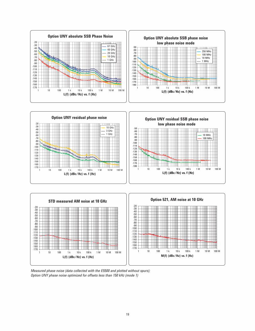
Option UNY absolute SSB Phase Noise-20-30-40-50-60-70-80-90
-100-110-120-130-140-150-160-170
L(f) (dBc/Hz) vs. f (Hz)1 10 100 1 k 10 k 100 k 1 M 10 M 100 M
67 GHz40 GHz20 GHz10 GHz1 GHz
Option UNY residual phase noise-20-30-40-50-60-70-80-90
-100-110-120-130-140-150-160-170
L(f) (dBc/Hz) vs. f (Hz)1 10 100 1 k 10 k 100 k 1 M 10 M 100 M
10 GHz3 GHz1 GHz
Option UNY absolute SSB phase noiselow phase noise mode
-50-60-70-80-90
-100-110-120-130-140-150-160-170-180
L(f) (dBc/Hz) vs. f (Hz)1 10 100 1 k 10 k 100 k 1 M 10 M 100 M
250 MHz100 MHz10 MHz1 MHz
Option UNY residual SSB phase noiselow phase noise mode
-50-60-70-80-90
-100-110-120-130-140-150-160-170-180
L(f) (dBc/Hz) vs. f (Hz)1 10 100 1 k 10 k 100 k 1 M 10 M 100 M
10 MHz100 MHz
Measured phase noise (data collected with the E5500 and plotted without spurs); Option UNY phase noise optimized for offsets less than 150 kHz (mode 1)
M(f) (dBc/Hz) vs. f (Hz)
Option 521, AM noise at 10 GHz-20-30-40-50-60-70-80-90
-100-110-120-130-140-150-160-170
1 10 100 1 k 10 k 100 k 1 M 10 M 100 M
Option UNY absolute SSB Phase Noise Option UNY absolute SSB phase noiselow phase noise mode
Option UNY residual phase noise
STD measured AM noise at 10 GHz Option 521, AM noise at 10 GHz
Option UNY residual SSB phase noiselow phase noise mode
19

L(f) (dBc/Hz) vs. f (Hz)
Option 521, UNX, absolute SSB phase noise-20-30-40-50-60-70-80-90
-100-110-120-130-140-150-160-170
1 10 100 1 k 10 k 100 k 1 M 10 M 100 M
20 GHz10 GHz1 GHz
L(f) (dBc/Hz) vs. f (Hz)
Option 521, UNX residual phase noise-20-30-40-50-60-70-80-90
-100-110-120-130-140-150-160-170
1 10 100 1 k 10 k 100 k 1 M 10 M 100 M
10 GHz3 GHz1 GHz
L(f) (dBc/Hz) vs. f (Hz)
Option 521, UNX low phase noise mode at 100 MHz
-170-160-150-140-130-120-110-100-90-80-70-60-50-40-30-20
1 10 100 1 k 10 k 100 k 1 M 10 M
-170-160-150-140-130-120-110-100
-90-80-70-60-50-40-30-20
1 10 100 1000 10000 100000100000010000000100000000
L(f) [dBc/Hz] vs. f [Hz]
Option 521, UNY absolute SSB phase noise
20 GHz10 GHz1 GHz
-170-160-150-140-130-120-110-100
-90-80-70-60-50-40-30-20
1 10 100 1000 10000 100000100000010000000100000000
L(f) [dBc/Hz] vs. f [Hz]
Option 521, UNY residual phase noise
10 GHz3 GHz1 GHz
-180-170-160-150-140-130-120-110-100
-90-80-70-60-50
1 10 100 1000 10000 100000100000010000000100000000
L(f) [dBc/Hz] vs. f [Hz]
Option 521, UNY absolute SSB phase noise low phase noise mode
250 MHz100 MHz10 MHz
Measured phase noise (data collected with the E5500 and plotted without spurs)Option UNY phase noise optimized for offsets less than 150 kHz (mode 1)
Option 521, UNX, absolute SSB phase noise
Option 521, UNX residual phase noise
Option 521, UNX absolute SSB phase noise low phase noise mode at 100 MHz
Option 521, UNY absolute SSB phase noiselow phase noise mode
Option 521, UNY residual phase noise
Option 521, UNY absolute SSB phase noise
L(f) (dBc/Hz) vs. f (Hz)
L(f) (dBc/Hz) vs. f (Hz)
L(f) (dBc/Hz) vs. f (Hz)
1 10 100 1 k 10 k 100 k 1 M 10 M 100 M1 10 100 1 k 10 k 100 k 1 M 10 M 100 M
1 10 100 1 k 10 k 100 k 1 M 10 M 100 M
1 10 100 1 k 10 k 100 k 1 M 10 M 100 M
1 10 100 1 k 10 k 100 k 1 M 10 M 100 M
20 GHz 10 GHz 1 GHz
20 GHz 10 GHz 1 GHz
10 GHz 3 GHz 1 GHz
10 GHz 3 GHz 1 GHz
250 GHz 100 GHz 10 GHz
20

1. Above 50 GHz, FM is useable; however performance is not warranted. 2. Through any combination of path1, path2, or path1 + path2. 3. Specifications apply in CW and list/step sweep modes. During ramp sweep operation (Option 007), 3 dB bandwidth is typically 50 kHz to 10 MHz (FM1 path), and
50 kHz to 1 MHz (FM2 path).4. At the calibrated deviation and carrier frequency, within 5 °C of ambient temperature at time of user calibration.
Frequency modulation 1 (Option UNT)Maximum deviation 2
Default RF path Frequency Max deviation250 kHz to 250 MHz 2 MHz> 250 to 500 MHz 1 MHz> 500 MHz to 1 GHz 2 MHz> 1 GHz to 2 GHz 4 MHz> 2 GHz to 3.2 GHz 8 MHz> 3.2 GHz to 10 GHz 16 MHz> 10 GHz to 20 GHz 32 MHz> 20 GHz to 40 GHz 64 MHz> 40 GHz to 67 GHz 128 MHz
Option UNX or UNY low phase noise mode Frequency Max deviation
> 0.98 to 1.953 MHz 3.906 kHz
> 1.953 to 3.906 MHz 7.8125 kHz
> 3.906 to 7.813 MHz 15.625 kHz
> 7.813 to 15.63 MHz 31.25 kHz
> 15.63 to 31.25 MHz 62.5 kHz
> 31.25 to 62.5 MHz 125 kHz
> 62.5 to 125 MHz 250 kHz
> 125 to 250 MHz 500 kHz
Resolution 0.1% of deviation or 1 Hz, whichever is greater
Deviation accuracy < ± 3.5% of FM deviation + 20 Hz (1 kHz rate, deviations < N x 800 kHz)
Modulation frequency response 3 (at 100 kHz deviation)
Path [coupling] 1 dB bandwidth 3 dB bandwidth (typ)
Standard or Option UNX
FM path 1 [DC] DC to 100 kHz DC to 10 MHz
FM path 2 [DC] DC to 100 kHz DC to 1 MHz
FM path 1 [AC] 20 Hz to 100 kHz 5 Hz to 10 MHz
FM path 2 [AC] 20 Hz to 100 kHz 5 Hz to 1 MHz
Option UNY
FM path 1 [DC] DC to 100 kHz DC to 9.3 MHz
FM path 2 [DC] DC to 100 kHz DC to 1 MHz
FM path 1 [AC] 20 Hz to 100 kHz 5 Hz to 9.3 MHz
FM path 2 [AC] 20 Hz to 100 kHz 5 Hz to 1 MHz
DC FM 4 carrier offset ±0.1% of set deviation + (N x 8 Hz)
21

Phase modulation 1 (Option UNT)Maximum deviation 2
Standard or Option UNX default RF path Frequency 100 kHz BW mode 1 MHz BW mode
250 kHz to 250 MHz 20 rad 2 rad
> 250 to 500 MHz 10 rad 1 rad
> 500 MHz to 1 GHz 20 rad 2 rad
> 1 GHz to 2 GHz 40 rad 4 rad
> 2 GHz to 3.2 GHz 80 rad 8 rad
> 3.2 GHz to 10 GHz 160 rad 16 rad
> 10 GHz to 20 GHz 320 rad 32 rad
> 20 GHz to 40 GHz 640 rad 64 rad
> 40 GHz to 67 GHz 1280 rad 128 rad
Option UNY default RF path Frequency 1 MHz BW mode 10 MHz BW mode
250 kHz to 250 MHz 2 rad 0.2 rad
> 250 to 500 MHz 1 rad 0.1 rad
> 500 MHz to 1 GHz 2 rad 0.2 rad
> 1 GHz to 2 GHz 4 rad 0.4 rad
> 2 GHz to 3.2 GHz 8 rad 0.8 rad
> 3.2 GHz to 10 GHz 16 rad 1.6 rad
> 10 GHz to 20 GHz 32 rad 3.2 rad
> 20 GHz to 40 GHz 64 rad 6.4 rad
> 40 GHz to 67 GHz 128 rad 12.8 rad
Option UNX low phase noise mode Frequency 100 kHz BW mode 1 MHz BW mode
> 0.98 to 1.953 MHz 0.03906 rad 0.003906 rad
> 1.953 to 3.906 MHz 0.078125 rad 0.0078125 rad
> 3.906 to 7.813 MHz 0.15625 rad 0.015625 rad
> 7.813 to 15.63 MHz 0.3125 rad 0.03125 rad
> 15.63 to 31.25 MHz 0.625 rad 0.0625 rad
> 31.25 to 62.5 MHz 1.25 rad 0.125 rad
> 62.5 to 125 MHz 2.5 rad 0.25 rad
> 125 to 250 MHz 5 rad 0.5 rad
1. Above 50 GHz, phase modulation is useable; however performance is not warranted.2. Through any combination of path1, path2, or path1 + path2.
Distortion < 1% (1 kHz rate, deviations < N x 800 kHz)
Sensitivity ±1 Vpeak for indicated deviation
PathsFM1 and FM2 are summed internally for composite modulation. Either path may be switched to any one of the modulation sources: Ext1, Ext2, internal1, internal2. The FM2 path is limited to a maximum rate of 1 MHz. The FM2 path must be set to a deviation less than FM1. To avoid distortion and clipping, signals applied with any combination of FM1, FM2, or FM1+FM2 should not exceed 1 Vpeak.
22

1. Specifications apply in CW and list/step sweep modes. During ramp sweep operation (Option 007), 3 dB bandwidth is typically 50 kHz to 1 MHz (high BW mode). 2. Path 1 is useable to 4 MHz for external inputs less than 0.3 Vpeak; useable to 8 MHz for external inputs less than 0.1 Vpeak.
Option UNY low phase noise mode Frequency 1 MHz BW mode 10 MHz BW mode
> 0.98 to 1.953 MHz 0.003906 rad 0.0003906 rad> 1.953 to 3.906 MHz 0.0078125 rad 0.00078125 rad> 3.906 to 7.813 MHz 0.015625 rad 0.0015625 rad> 7.813 to 15.63 MHz 0.03125 rad 0.003125 rad> 15.63 to 31.25 MHz 0.0625 rad 0.00625 rad> 31.25 to 62.5 MHz 0.125 rad 0.0125 rad> 62.5 to 125 MHz 0.25 rad 0.025 rad> 125 to 250 MHz 0.5 rad 0.05 rad
Resolution 0.1% of set deviationDeviation accuracy < ±5% of deviation + 0.01 radians (1 kHz rate with 1 MHz BW mode for Option UNY or 100 kHz BW mode otherwise)Modulation frequency response 1 Rates (3 dB bandwidth) Standard UNX UNY100 kHz BW mode DC to 100 kHz Normal Normal n/a1 MHz BW mode DC to 1 MHz (typ) 2 High High Normal10 MHz BW mode DC to 10 MHz (typ) n/a n/a HighDistortionStandard or Option UNX < 1% (1 kHz rate, total harmonic distortion (THD), deviation < N x 80 rad, 100 kHz BW mode)Option UNY < 1% (1 kHz rate, total harmonic distortion (THD), deviation < N x 8 rad, 1 MHz BW mode)Sensitivity ±1 Vpeak for indicated deviationPaths ΦM1 and ΦM2 are summed internally for composite modulation. Either path may be switched to any
one of the modulation sources: Ext1, Ext2, internal1, internal2. The ΦM2 path is limited to a maximum rate of 1 MHz. The ΦM2 path must be set to a deviation less than ΦM1. To avoid distortion and clipping, signals applied with any combination of ΦM1, ΦM2, or ΦM1+ ΦM2 should not exceed 1 Vpeak.
23

1. All AM specifications are typical. For carrier frequencies below 2 MHz or above 50 GHz, AM is useable but not specified. Unless otherwise stated, specifications apply with ALC on, deep AM off, and envelope peaks within ALC operating range (–20 dBm to maximum output power, excluding step-attenuator setting.)
2. Below 250 MHz with Option UNX or UNY low phase noise mode on, AM is useable but not recommended or specified.3. Option 1SM scan modulation is available with Option 520 only, and provides exponential (log) AM with improved accuracy. In this mode, maximum output power
is reduced up to 3 dB below 3.2 GHz. 4. ALC off is used for narrow pulse modulation and/or high AM depths with envelope peaks below ALC operating range (40 dB). Carrier power level will be accurate
after a power search is executed. (See pulse modulation section for an explanation of power search). 5. Deep AM with ALC on provides increased AM depths and improved distortion, together with closed-loop internal leveling. This mode must be used with a repetitive
AM waveform (frequency > 10 Hz) with peaks > –5 dBm (nominal, excluding step-attenuator setting).6. Modulation depths greater than 40 dB require an external input greater than ±1 V, and are not available with the internal modulation source.7. If 600 Ω input impedance is selected, maximum input voltage is ±6 V.8. For Options 550 and 567, maximum rate is 80 kHz from 20 GHz to 40 GHz. 9. For Option 521, distortion specifications apply for envelope peaks within the range of -15 dBm to +24 dBm, excluding step-attenuator setting.
Amplitude modulation 1, 2 (Option UNT) (typical)Depth Linear mode Exponential (log) mode (downward modulation only)
Option UNT Option UNT + 1SM 3
Maximum ALC on > 90% > 20 dB > 20 dB ALC off with power search 4
or ALC on with deep AM 5 > 95% > 50 dB 6 > 60 dB6
Settable 0 to 100% 0 to 40 dB 0 to 40 dB
Sensitivity 0 to 100 %/V 0 to 40 dB/V 0 to 40 dB/V
Resolution 0.1% 0.01 dB 0.01 dB
Depth accuracy (1 kHz rate)ALC on ±(6% of setting + 1%) ±(2% of setting + 0.2 dB) ±(2% of setting + 0.2 dB)ALC off with power search 4 or ALC on with deep AM 5
< 2 dB depth -- -- ±0.5 dB
< 10 dB depth -- -- ±1 dB
< 40 dB depth -- -- ±2 dB
< 50 dB depth -- -- ±3 dB
< 60 dB depth -- -- ±5 dB
External input (selectable polarity)
Sensitivity for indicated depth 1 Vpeak –1 V or +1 V –1 V or +1 V
Maximum allowable ±1 V ±3.5 V 7 ±3.5 V 7
Rates (3 dB bandwidth, 30% depth)
DC coupled 0 to 100 kHz
AC coupled 10 Hz to 100 kHz (useable to 1 MHz) 8
Distortion 9 (1 kHz rate, ALC On, linear mode, total harmonic distortion)
30% AM < 1.5%
60% AM < 2%
Paths AM1 and AM2 are summed internally for composite modulation. Either path may be switched to any one of the modulation sources: Ext1, Ext2, Internal1, Internal2
24

1. Internal2 is not available when using swept sine or dual sine modes.
External modulation inputs (Ext1 & Ext2) (Option UNT)Modulation types AM, FM, and ΦMInput impedance 50 Ω or 600 Ω (nom) switchedHigh/low indicator 100 Hz to 10 MHz BW, activated when input level error exceeds 3% (nom), ac coupled inputs only
Internal modulation source (Option UNT)Dual function generators Provide two independent signals (internal1 and internal2) for use with AM, FM, ΦM, or LF out.Waveforms Sine, square, positive ramp, negative ramp, triangle, Gaussian noise, uniform noise, swept sine, dual sine 1
Rate rangeSine 0.5 Hz to 1 MHz
Square, ramp, triangle 0.5 Hz to 100 kHz
Resolution 0.5 HzAccuracy Same as timebaseLF outOutput Internal1 or internal2. Also provides monitoring of internal1 or internal2 when used for AM, FM, or ΦMAmplitude 0 to 3 Vpeak (nom) into 50 ΩOutput impedance 50 Ω (nom)Swept sine mode (frequency, phase continuous)Operating modes Triggered or continuous sweepsFrequency range 1 Hz to 1 MHzSweep rate 0.5 to 100,000 sweeps/s, equivalent to sweep times 10 μs to 2 sResolution 0.5 Hz (0.5 sweep/s)
25

Pulse modulation 1 (Option UNU or UNW)On/off ratio Option UNU Option UNW
80 dB (typ) 80 dBRise/fall times (Tr, Tf)
Options 520, 532, 540, 550, 567
50 to 400 MHz 10 ns (typ) 15 ns (10 ns typ)
> 400 MHz 6 ns (typ) 10 ns (6 ns typ)
Option 521
50 MHz to 1 GHz 25 ns (typ) 30 ns (25 ns typ)
1 to 3.2 GHz 12 ns (typ) 15 ns (12 ns typ)
> 3.2 GHz 6 ns (typ) 10 ns (6 ns typ)
Minimum pulse width
ALC on 1 μs 1 μs
ALC offOptions 520, 532, 540, 550, 567
50 to 400 MHz 150 ns 30 ns> 400 MHz 150 ns 20 ns
Option 52150 MHz to 1 GHz 150 ns 60 ns1 to 3.2 GHz 150 ns 30 ns> 3.2 GHz 150 ns 20 ns
Repetition frequencyALC on 10 Hz to 500 kHz 10 Hz to 500 kHzALC off dc to 3 MHz dc to 10 MHzLevel accuracy (relative to CW)ALC on ±0.5 dB (0.15 dB typ) ±0.5 dB (0.15 dB typ)
ALC off with power search 2
50 MHz to 3.2 GHz 3 ±0.7 dB (typ) ±0.7 dB (typ)
> 3.2 GHz ±0.5 dB (typ) ±0.5 dB (typ)
Width compression (RF width relative to video out) ±5 ns (typical) ±5 ns (typical)
1. With ALC off, specs apply after the execution of power search. Specifications apply with Atten Hold Off (default mode for instruments with attenuator), or ALC level between –5 and +10 dBm or maximum specified power, whichever is lower. Above 50 GHz or below 50 MHz, pulse modulation is useable; however performance is not warranted. Pulse modulation does not operate if Option UNX or UNY low phase noise mode is on.
2. Power Search is a calibration routine that improves level accuracy with ALC off. The instrument microprocessor momentarily closes the ALC loop to find the modulator drive setting necessary to make the quiescent RF level equal to an entered value, then opens the ALC loop while maintaining that modulator drive setting. When executing Power Search, RF power will be present for typically 10 to 50 ms; the step attenuator (Option 1E1) can be set to automatically switch to maximum attenuation to protect sensitive devices. Power search can be configured to operate either automatically or manually at the carrier frequency, or over a user-definable frequency range. Power search may not operate above the maximum specified output power.
3. ± 0.8 dB (typical) for Option 550 and Option 567.
26
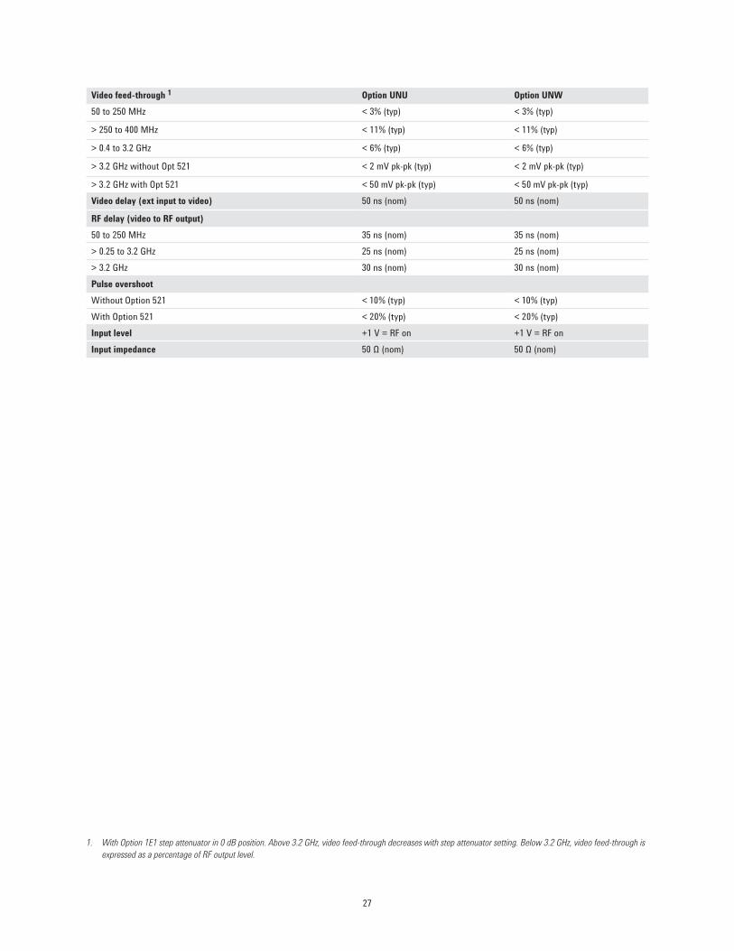
1. With Option 1E1 step attenuator in 0 dB position. Above 3.2 GHz, video feed-through decreases with step attenuator setting. Below 3.2 GHz, video feed-through is expressed as a percentage of RF output level.
Video feed-through 1 Option UNU Option UNW50 to 250 MHz < 3% (typ) < 3% (typ)
> 250 to 400 MHz < 11% (typ) < 11% (typ)
> 0.4 to 3.2 GHz < 6% (typ) < 6% (typ)
> 3.2 GHz without Opt 521 < 2 mV pk-pk (typ) < 2 mV pk-pk (typ)
> 3.2 GHz with Opt 521 < 50 mV pk-pk (typ) < 50 mV pk-pk (typ)Video delay (ext input to video) 50 ns (nom) 50 ns (nom)
RF delay (video to RF output)50 to 250 MHz 35 ns (nom) 35 ns (nom)> 0.25 to 3.2 GHz 25 ns (nom) 25 ns (nom)> 3.2 GHz 30 ns (nom) 30 ns (nom)Pulse overshootWithout Option 521 < 10% (typ) < 10% (typ)With Option 521 < 20% (typ) < 20% (typ)Input level +1 V = RF on +1 V = RF onInput impedance 50 Ω (nom) 50 Ω (nom)
27

Internal pulse generator (Option UNU or UNW)Modes Free-run, triggered, triggered with delay, doublet, and gated. Triggered with delay, doublet, and
gated require external trigger source.Period (PRI) (Tp) 70 ns to 42 s (repetition frequency: 0.024 Hz to 14.28 MHz)Pulse width (Tw) 10 ns to 42 s
Delay (Td)
Free-run mode 0 to ±42 s
Triggered with delay and doublet modes 75 ns to 42 s with ±10 ns jitter
Resolution 10 ns (width, delay, and PRI)
SyncOutput
VideoOutput
RF PulseOutput
Td
Tm
Tw
Trf
Vf
TfTr
Vor
Tp
50%
50%
10%
90%
50%
•Tdvideodelay(variable)
•Twvideopulsewidth(variable)
•TpPulseperiod(variable)
•TmRFdelay
•TrfRFpulsewidth
•TfRFpulsefalltime
•TrRFpulserisetime
•Vorpulseovershoot
•Vfvideofeedthrough
Simultaneous modulationAll modulation types (FM, AM, φM, and pulse modulation) may be simultaneously enabled except: FM with φM, and linear AM with exponential AM. AM, FM, and φM can sum simultaneous inputs from any two sources (Ext1, Ext2, internal1, or internal2). Any given source (Ext1, Ext2, internal1, or internal2) may be routed to only one activated modulation type.
Measured pulse modulation envelopeFrequency = 9 GHz, amplitude = 10 dBm, ALC Off, 10 ns/div
28

Remote programmingInterfaces GPIB (IEEE-488.2,1987) with listen and talk, RS-232, and 10BaseT LAN interface.
Control languages SCPI version 1997.0. Completely code compatible with previous PSG signal generator models:•E8241A•E8244A•E8251A•E8254A•E8247C•E8257CThe E8257D will emulate the applicable commands for the following signal generators, providing general compatibility with ATE systems:•Agilent8340-Series(8340/41B)•Agilent8360-Series(836xxB/L)•Agilent83700-Series(837xxB)
•Agilent8662A/63A
•Agilent8643A/8644B•Aeroflex2040Series
IEEE-488 functions SH1, AH1, T6, TE0, L4, LE0, SR1, RL1, PP0, DC1, DT0, C0, E2.
Agilent IO libraries Agilent’s IO Library Suite ships with the E8257D to help you quickly establish an error-free connection between your PC and instruments – regardless of the vendor. It provides robust instrument control and works with the software development environment you choose.
29

General specificationsPower requirements 100/120 VAC 50/60/400 Hz; or 220/240 VAC 50/60 Hz, (automatically selected);
< 250 W typical, 450 W maximumOperating temperature range 0 to 55 °C
Storage temperature range 1 –40 to 70 °C
Altitude 0 to 4600 m (15,000 ft.)
Humidity Relative humidity - type tested at 95%, +40°C (non-condensing)
Environmental testing Samples of this product have been tested in accordance with the Agilent Environmental Test Manual and verified to be robust against the environmental stresses of storage, transportation, and end-use; those stresses include but are not limited to temperature, humidity, shock, vibration, altitude, and power line conditions. Test methods are aligned with IEC 60068-2 and levels are similar to MIL-PRF-28800F Class 3. 2
ISO compliant This family of signal generators is manufactured in an ISO-9001 registered facility in concurrence with Agilent's commitment to quality.
EMC Conforms to the immunity and emission requirements of IEC/EN 61326-1 including the conducted and radiated emission requirements of CISPR Pub 11/2003 Group 1 class A.
Acoustic noise Normal: 51 dBA (nom) Worst case: 62 dBA (nom) 3
Storage Memoryissharedbyinstrumentstatesandsweeplistfiles.Thereis14MBofflashmemoryavailable in the E8257D PSG. Depending on how the memory is used, a maximum of 1000 instrument states can be saved.
Security Display blanking Memory clearing functions (See Application Note, "Security Features of Agilent Technologies Signal Generators," Part Number E4400-90621) WithOption008,alluser-writtenfilesarestoredonan8GByteremovableflashmemorycard.
Compatibility Agilent 83550 Series millimeter heads OML millimeter source modules Agilent 8757D scalar network analyzers Agilent EPM Series power meters
Self-test Internal diagnostic routine tests most modules (including microcircuits) in a preset condition. For each module, if its node voltages are within acceptable limits, then the module “passes” the test.
Weight < 22 kg (48 lb.) net, < 30 kg (68 lb.) shipping
Dimensions 178 mm H x 426 mm W x 515 mm D (7” H x 16.8” W x 20.3” D)
Recommended calibration cycle 24 months
1. During storage below -20 °C, instrument states may be lost.2. As is the case with all signal generation equipment, phase noise specifications are not warranted in a vibrating environment.3. This is louder than typical Agilent equipment: 60 dBA (nom).
30

Input/Output Descriptions
1. Digital inputs and outputs are 3.3 V CMOS unless indicated otherwise. Inputs will accept 5 V CMOS, 3 V CMOS, or TTL voltage levels.
Front panel connectors (all connectors are BNC female unless otherwise noted.) 1RF output Output impedance 50 Ω (nom)
Option 520 and 521 Precision APC-3.5 male, or Type-N female with Option 1ED Caution: Option 521 output power > 1 Watt
Options 532, 540, and 550 Precision 2.4 mm male; plus 2.4 – 2.4 mm and 2.4 – 2.9 mm female adapters
Option 567 Precision 1.85 mm male; plus 1.85 – 1.85 mm and 2.4 – 2.9 mm female adapters
ALC input Used for negative external detector leveling. Nominal input impedance 120 kΩ, damage level ±15 V.
LF output Outputs the internally generated LF source. Nominal output impedance 50 Ω.
External input 1 Drives either AM, FM, or ΦM. Nominal input impedance 50 or 600 Ω, damage levels are 5 Vrms and 10 Vpeak.
External input 2 Drives either AM, FM, or ΦM. Nominal input impedance 50 or 600 Ω, damage levels are 5 Vrms and 10 Vpeak.
Pulse/trigger gate input Accepts input signal for external fast pulse modulation. Also accepts external trigger pulse input for internal pulse modulation. Nominal impedance 50 Ω. Damage levels are 5 Vrms and 10 Vpeak.
Pulse video out Outputs a signal that follows the RF output in all pulse modes. TTL-level compatible, nominal source impedance 50 Ω.
Pulse sync out Outputs a synchronizing pulse, nominally 50 ns width, during internal and triggered pulse modulation. TTL-level compatible, nominal source impedance 50 Ω.
31
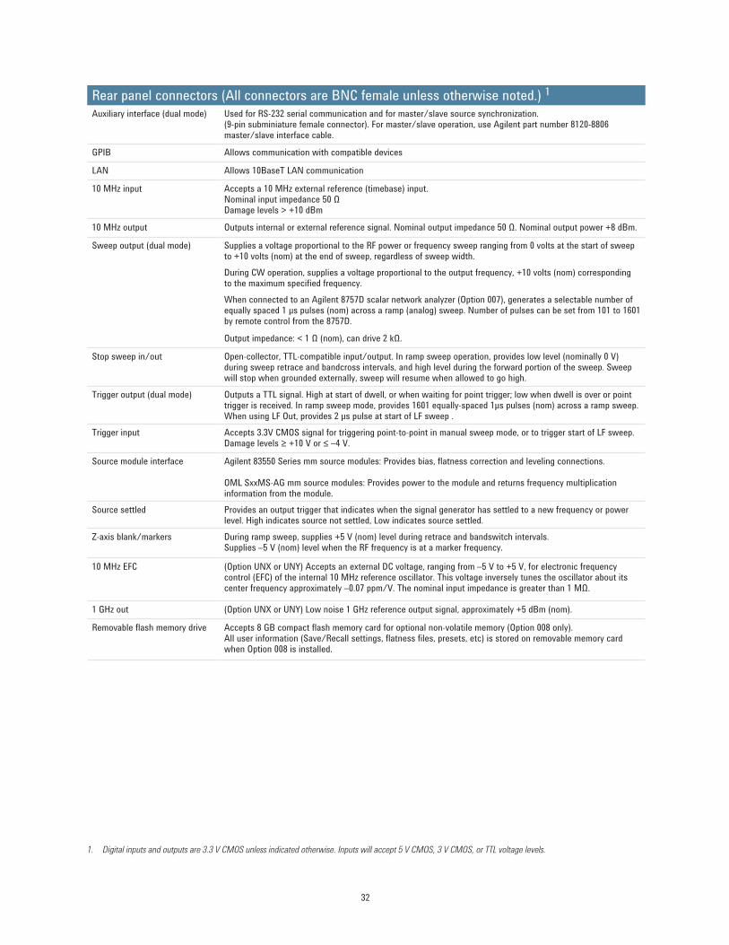
1. Digital inputs and outputs are 3.3 V CMOS unless indicated otherwise. Inputs will accept 5 V CMOS, 3 V CMOS, or TTL voltage levels.
Rear panel connectors (All connectors are BNC female unless otherwise noted.) 1Auxiliary interface (dual mode) Used for RS-232 serial communication and for master/slave source synchronization.
(9-pin subminiature female connector). For master/slave operation, use Agilent part number 8120-8806 master/slave interface cable.
GPIB Allows communication with compatible devices
LAN Allows 10BaseT LAN communication
10 MHz input Accepts a 10 MHz external reference (timebase) input. Nominal input impedance 50 Ω Damage levels > +10 dBm
10 MHz output Outputs internal or external reference signal. Nominal output impedance 50 Ω. Nominal output power +8 dBm.
Sweep output (dual mode) Supplies a voltage proportional to the RF power or frequency sweep ranging from 0 volts at the start of sweep to +10 volts (nom) at the end of sweep, regardless of sweep width.During CW operation, supplies a voltage proportional to the output frequency, +10 volts (nom) corresponding to the maximum specified frequency.When connected to an Agilent 8757D scalar network analyzer (Option 007), generates a selectable number of equally spaced 1 μs pulses (nom) across a ramp (analog) sweep. Number of pulses can be set from 101 to 1601 by remote control from the 8757D.
Output impedance: < 1 Ω (nom), can drive 2 kΩ.
Stop sweep in/out Open-collector, TTL-compatible input/output. In ramp sweep operation, provides low level (nominally 0 V)during sweep retrace and bandcross intervals, and high level during the forward portion of the sweep. Sweep will stop when grounded externally, sweep will resume when allowed to go high.
Trigger output (dual mode) Outputs a TTL signal. High at start of dwell, or when waiting for point trigger; low when dwell is over or point trigger is received. In ramp sweep mode, provides 1601 equally-spaced 1μs pulses (nom) across a ramp sweep. When using LF Out, provides 2 μs pulse at start of LF sweep .
Trigger input Accepts 3.3V CMOS signal for triggering point-to-point in manual sweep mode, or to trigger start of LF sweep. Damage levels ≥ +10 V or ≤ –4 V.
Source module interface Agilent83550Seriesmmsourcemodules:Providesbias,flatnesscorrectionandlevelingconnections. OML SxxMS-AG mm source modules: Provides power to the module and returns frequency multiplication information from the module.
Source settled Provides an output trigger that indicates when the signal generator has settled to a new frequency or power level. High indicates source not settled, Low indicates source settled.
Z-axis blank/markers During ramp sweep, supplies +5 V (nom) level during retrace and bandswitch intervals. Supplies –5 V (nom) level when the RF frequency is at a marker frequency.
10 MHz EFC (Option UNX or UNY) Accepts an external DC voltage, ranging from –5 V to +5 V, for electronic frequency control (EFC) of the internal 10 MHz reference oscillator. This voltage inversely tunes the oscillator about its center frequency approximately –0.07 ppm/V. The nominal input impedance is greater than 1 MΩ.
1 GHz out (Option UNX or UNY) Low noise 1 GHz reference output signal, approximately +5 dBm (nom).
Removableflashmemorydrive Accepts8GBcompactflashmemorycardforoptionalnon-volatilememory(Option008only). Alluserinformation(Save/Recallsettings,flatnessfiles,presets,etc)isstoredonremovablememorycardwhen Option 008 is installed.
32
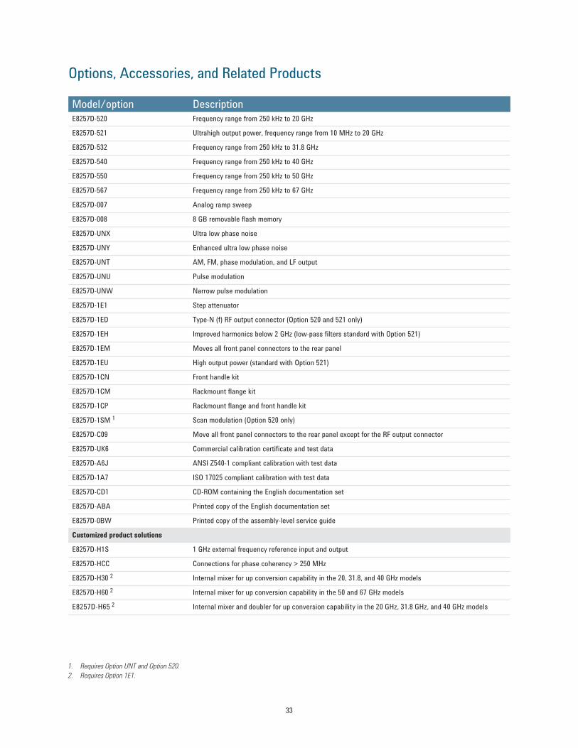
Model/option DescriptionE8257D-520 Frequency range from 250 kHz to 20 GHz
E8257D-521 Ultrahigh output power, frequency range from 10 MHz to 20 GHz
E8257D-532 Frequency range from 250 kHz to 31.8 GHz
E8257D-540 Frequency range from 250 kHz to 40 GHz
E8257D-550 Frequency range from 250 kHz to 50 GHz
E8257D-567 Frequency range from 250 kHz to 67 GHz
E8257D-007 Analog ramp sweep
E8257D-008 8GBremovableflashmemory
E8257D-UNX Ultra low phase noise
E8257D-UNY Enhanced ultra low phase noise
E8257D-UNT AM, FM, phase modulation, and LF output
E8257D-UNU Pulse modulation
E8257D-UNW Narrow pulse modulation
E8257D-1E1 Step attenuator
E8257D-1ED Type-N (f) RF output connector (Option 520 and 521 only)
E8257D-1EH Improved harmonics below 2 GHz (low-pass filters standard with Option 521)
E8257D-1EM Moves all front panel connectors to the rear panel
E8257D-1EU High output power (standard with Option 521)
E8257D-1CN Front handle kit
E8257D-1CM Rackmountflangekit
E8257D-1CP Rackmountflangeandfronthandlekit
E8257D-1SM 1 Scan modulation (Option 520 only)
E8257D-C09 Move all front panel connectors to the rear panel except for the RF output connector
E8257D-UK6 Commercial calibration certificate and test data
E8257D-A6J ANSI Z540-1 compliant calibration with test data
E8257D-1A7 ISO 17025 compliant calibration with test data
E8257D-CD1 CD-ROM containing the English documentation set
E8257D-ABA Printed copy of the English documentation set
E8257D-0BW Printed copy of the assembly-level service guide
Customized product solutions
E8257D-H1S 1 GHz external frequency reference input and output
E8257D-HCC Connections for phase coherency > 250 MHz
E8257D-H30 2 Internal mixer for up conversion capability in the 20, 31.8, and 40 GHz models
E8257D-H60 2 Internal mixer for up conversion capability in the 50 and 67 GHz models
E8257D-H65 2 Internal mixer and doubler for up conversion capability in the 20 GHz, 31.8 GHz, and 40 GHz models
1. Requires Option UNT and Option 520. 2. Requires Option 1E1.
Options, Accessories, and Related Products
33

1. Millimeter source module is a product of Oleson Microwave Labs, Inc. and requires Option 1EU.
Accessories
8120-8806 Master/slave interface cable
1819-0427 8GBytecompactflashmemorycard
E8251-60419 Rack slide kit
E8257DS15 1 OML Inc. Millimeter source module, 50 GHz to 75 GHz at +8 dBm
E8257DS12 1 OML Inc. Millimeter source module, 60 GHz to 90 GHz at +6 dBm
E8257DS10 1 OML Inc. Millimeter source module, 75 GHz to 110 GHz at +5 dBm
E8257DS08 1 OML Inc. Millimeter source module, 90 GHz to 140 GHz at –2 dBm
E8257DS06 1 OML Inc. Millimeter source module, 110 GHz to 170 GHz at –6 dBm
E8257DS05 1 OML Inc. Millimeter source module, 140 GHz to 220 GHz at –12 dBm
E8257DS03 1 OML Inc. Millimeter source module, 220 GHz to 325 GHz at –25 dBm
E8257DS02 1 OML Inc. Millimeter source module, 325 GHz to 500 GHz at –35 dBm
34

Related Agilent LiteratureAgilent PSG Microwave Signal Generators Brochure, Literature number 5989-1324ENE8257D PSG Microwave Analog Signal Generators Configuration Guide, Literature number 5989-1325ENE8267D PSG Microwave Vector Signal Generator Data Sheet, Literature number 5989-0697ENE8267D PSG Microwave Vector Signal Generator Configuration Guide, Literature number 5989-1326ENE8663D PSG RF Analog Signal Generator Data Sheet, Literature number 5990-4136ENE8663D PSG RF Analog Signal Generator Configuration Guide, Literature number 5990-4137ENMillimeter Wave Source Modules from OML, Inc. for the Agilent PSG Signal Generators Technical Overview, Literature number 5989-2923ENSecurity Features of Agilent Technologies Signal Generators, Part Number E4400-90621
Web ResourcesFor additional information, visit: www.agilent.com/find/psgFor more information about renting, leasing or financing Agilent’s latest technology, visit: www.agilent.com/find/buy/alternativesFor more accessory information, visit: www.agilent.com/find/accessoriesFor additional description of Agilent’s IO Libraries Suite features and installation requirements, visit: www.agilent.com/find/iosuite/database
www.lxistandard.orgLAN eXtensions for Instruments puts the power of Ethernet and the Web inside your test systems. Agilent is a founding member of the LXI consortium.
www.agilent.com/find/emailupdatesGet the latest information on the products and applications you select.
Agilent Channel Partners
www.agilent.com/find/channelpartnersGet the best of both worlds: Agilent’s measurement expertise and product breadth, combined with channel partner convenience.
www.agilent.com
Agilent Advantage Services is committed to your success throughout your equip-ment’s lifetime. To keep you competitive, we continually invest in tools and processes that speed up calibration and repair and reduce your cost of ownership. You can also use Infoline Web Services to manage equipment and services more effectively. By sharing our measurement and service expertise, we help you create the products that change our world.
www.agilent.com/quality
www.agilent.com/find/advantageservices
For more information on Agilent Technologies’ products, applications or services, please contact your local Agilent office. The complete list is available at:www.agilent.com/find/contactus
AmericasCanada (877) 894 4414 Brazil (11) 4197 3600Mexico 01800 5064 800 United States (800) 829 4444
Asia PacificAustralia 1 800 629 485China 800 810 0189Hong Kong 800 938 693India 1 800 112 929Japan 0120 (421) 345Korea 080 769 0800Malaysia 1 800 888 848Singapore 1 800 375 8100Taiwan 0800 047 866Other AP Countries (65) 375 8100
Europe & Middle EastBelgium 32 (0) 2 404 93 40 Denmark 45 45 80 12 15Finland 358 (0) 10 855 2100France 0825 010 700* *0.125 €/minuteGermany 49 (0) 7031 464 6333 Ireland 1890 924 204Israel 972-3-9288-504/544Italy 39 02 92 60 8484Netherlands 31 (0) 20 547 2111Spain 34 (91) 631 3300Sweden 0200-88 22 55United Kingdom 44 (0) 118 927 6201For other unlisted countries: www.agilent.com/find/contactusRevised: January 6, 2012
Product specifications and descriptions in this document subject to change without notice.
© Agilent Technologies, Inc. 2012Published in USA, August 1 4, 20125989-0698EN