Embed Size (px)
Citation preview
Agilent
E3640A – E3649A
Programmable DC Power Supplies
Data Sheet
2
Reliable Power, Repeatable Results
Single and dual outputs
Dual range output
30 W to 100 W output power
Front and rear output terminals
Over-voltage protection
Remote Sensing
GPIB and RS-232 standard
Save and recall functions
Great Performance,
Outstanding PriceWith the output power of 30 to
100 W, the Agilent E364xA Series
programmable DC power supplies
provide great performance at a great
price. All ten models deliver clean
power, excellent regulation, fast
transient response and built-in GPIB
and RS-232 interfaces. They are
designed to meet the needs of R&D
design verification, production testing,
QA verifications, and other demanding
applications with Agilent
Technologies’s quality and reliability.
Steady OutputWith 0.01 percent load and line
regulation, Agilent E364xA power
supplies are able to maintain a steady
output when power line and load
changes occur. They also specify
normal mode voltage noise and low
common mode current noise. The
low normal mode noise specification
assures clean power for precision
circuitry applications, and the low
common mode current provides
isolation from power line current
injection. Agilent E364xA power
supplies specify less than 90 msec
of voltage settling time at any output
load condition.
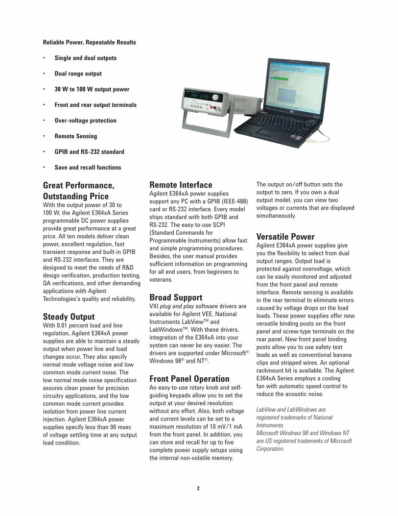
Remote InterfaceAgilent E364xA power supplies
support any PC with a GPIB (IEEE-488)
card or RS-232 interface. Every model
ships standard with both GPIB and
RS-232. The easy-to-use SCPI
(Standard Commands for
Programmable Instruments) allow fast
and simple programming procedures.
Besides, the user manual provides
sufficient information on programming
for all end users, from beginners to
veterans.
Broad SupportVXI plug and play software drivers are
available for Agilent VEE, National
Instruments LabViewTM and
LabWindowsTM. With these drivers,
integration of the E364xA into your
system can never be any easier. The
drivers are supported under Microsoft®
Windows 98® and NT®.
Front Panel OperationAn easy-to-use rotary knob and self-
guiding keypads allow you to set the
output at your desired resolution
without any effort. Also, both voltage
and current levels can be set to a
maximum resolution of 10 mV/1 mA
from the front panel. In addition, you
can store and recall for up to five
complete power supply setups using
the internal non-volatile memory.
The output on/off button sets the
output to zero. If you own a dual
output model, you can view two
voltages or currents that are displayed
simultaneously.
Versatile PowerAgilent E364xA power supplies give
you the flexibility to select from dual
output ranges. Output load is
protected against overvoltage, which
can be easily monitored and adjusted
from the front panel and remote
interface. Remote sensing is available
in the rear terminal to eliminate errors
caused by voltage drops on the load
leads. These power supplies offer new
versatile binding posts on the front
panel and screw-type terminals on the
rear panel. New front panel binding
posts allow you to use safety test
leads as well as conventional banana
clips and stripped wires. An optional
rackmount kit is available. The Agilent
E364xA Series employs a cooling
fan with automatic speed control to
reduce the acoustic noise.
LabView and LabWindows are
registered trademarks of National
Instruments.
Microsoft Windows 98 and Windows NT
are US registered trademerks of Microsoft
Corporation.
3
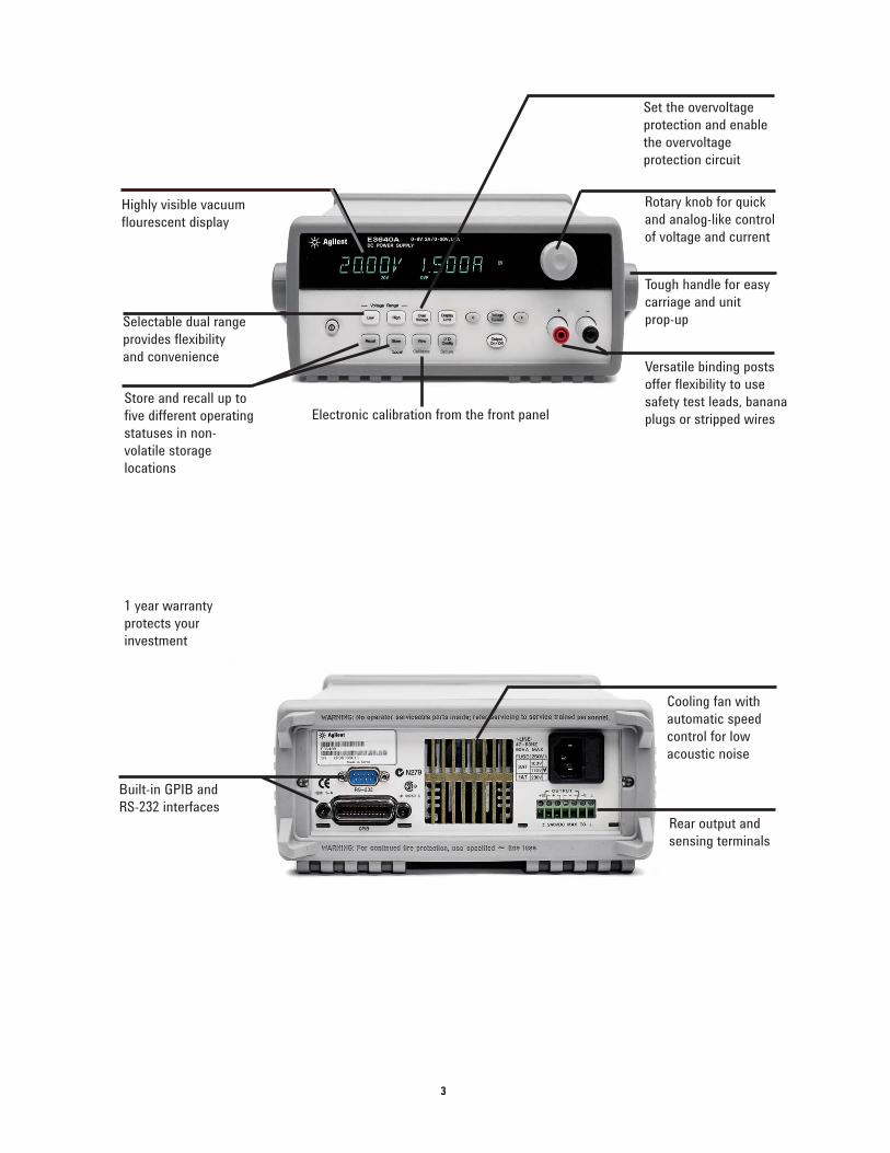
Highly visible vacuum
flourescent display
Selectable dual range
provides flexibility
and convenience
Electronic calibration from the front panel
Rotary knob for quick
and analog-like control
of voltage and current
Tough handle for easy
carriage and unit
prop-up
Versatile binding posts
offer flexibility to use
safety test leads, banana
plugs or stripped wires
1 year warranty
protects your
investment
Built-in GPIB and
RS-232 interfaces
Cooling fan with
automatic speed
control for low
acoustic noise
Rear output and
sensing terminals
Store and recall up to
five different operating
statuses in non-
volatile storage
locations
Set the overvoltage
protection and enable
the overvoltage
protection circuit
4
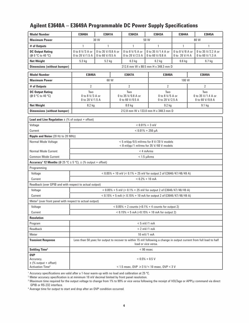
Agilent E3640A – E3649A Programmable DC Power Supply Specifications
Model Number E3640A E3641A E3642A E3643A E3644A E3645A
Maximum Power 30 W 50 W 80 W
# of Outputs 1 1 1 1 1 1
DC Output Rating
(@ 0 ºC to 40 ºC)
0 to 8 V/3 A or
0 to 20 V/1.5 A
0 to 35 V/0.8 A or
0 to 60 V/0.5 A
0 to 8 V/5 A or
0 to 20 V/2.5 A
0 to 35 V/1.4 A or
0 to 60 V/0.8 A
0 to 8 V/8 A or
0 to 20 V/4 A
0 to 35 V/2.2 A or
0 to 60 V/1.3 A
Net Weight 5.3 kg 5.2 kg 6.3 kg 6.2 kg 6.6 kg 6.7 kg
Dimensions (without bumper) 212.6 mm W x 88.5 mm H x 348.3 mm D
Model Number E3646A E3647A E3648A E3649A
Maximum Power 60 W 100 W
# of Outputs 2 2 2 2
DC Output Rating
(@ 0 ºC to 40 ºC)
Two
0 to 8 V/3 A or
0 to 20 V/1.5 A
Two
0 to 35 V/0.8 A or
0 to 60 V/0.5 A
Two
0 to 8 V/5 A or
0 to 20 V/2.5 A
Two
0 to 35 V/1.4 A or
0 to 60 V/0.8 A
Net Weight 8.2 kg 8.0 kg 9.2 kg 9.1 kg
Dimensions (without bumper) 212.8 mm W x 133.0 mm H x 348.3 mm D
Load and Line Regulation ± (% of output + offset)
Voltage < 0.01% + 3 mV
Current < 0.01% + 250 μA
Ripple and Noise (20 Hz to 20 MHz)
Normal Mode Voltage < 5 mVpp/0.5 mVrms for 8 V/20 V models
< 8 mVpp/1 mVrms for 35 V/60 V models
Normal Mode Current < 4 mArms
Common Mode Current < 1.5 μArms
Accuracy1 12 Months (@ 25 ºC ± 5 ºC), ± (% output + offset)
Programming
Voltage < 0.05% + 10 mV (< 0.1% + 25 mV for output 2 of E3646/47/48/49 A)
Current < 0.2% + 10 mA
Readback (over GPIB and with respect to actual output)
Voltage < 0.05% + 5 mV (< 0.1% + 25 mV for output 2 of E3646/47/48/49 A)
Current < 0.15% + 5 mA (< 0.15% + 10 mA for output 2 of E3646/47/48/49 A)
Meter2 (over front panel with respect to actual output)
Voltage < 0.05% + 2 counts (<0.1% + 4 counts for output 2)
Current < 0.15% + 5 mA (<0.15% + 10 mA for output 2)
Resolution
Program < 5 mV/1 mA
Readback < 2 mV/1 mA
Meter 10 mV/1 mA
Transient Response Less than 50 μsec for output to recover to within 15 mV following a change in output current from full load to half
load or vice versa.
Settling Time3 < 90 msec
OVP
Accuracy,
± (% output + offset)
Activation Time4
< 0.5% + 0.5 V
< 1.5 msec, OVP ¥3 V/< 10 msec, OVP < 3 V
1 Accuracy specifications are valid after a 1-hour warm-up with no load and calibration at 25 ºC.2 Meter accuracy specification is at minimum 10 mV decimal limited by front panel resolution.3 Maximum time required for the output voltage to change from 1% to 99% or vice versa following the receipt of VOLTage or APPLy command via direct
GPIB or RS-232 interface.4 Average time for output to start and drop after an OVP condition occurred.
5
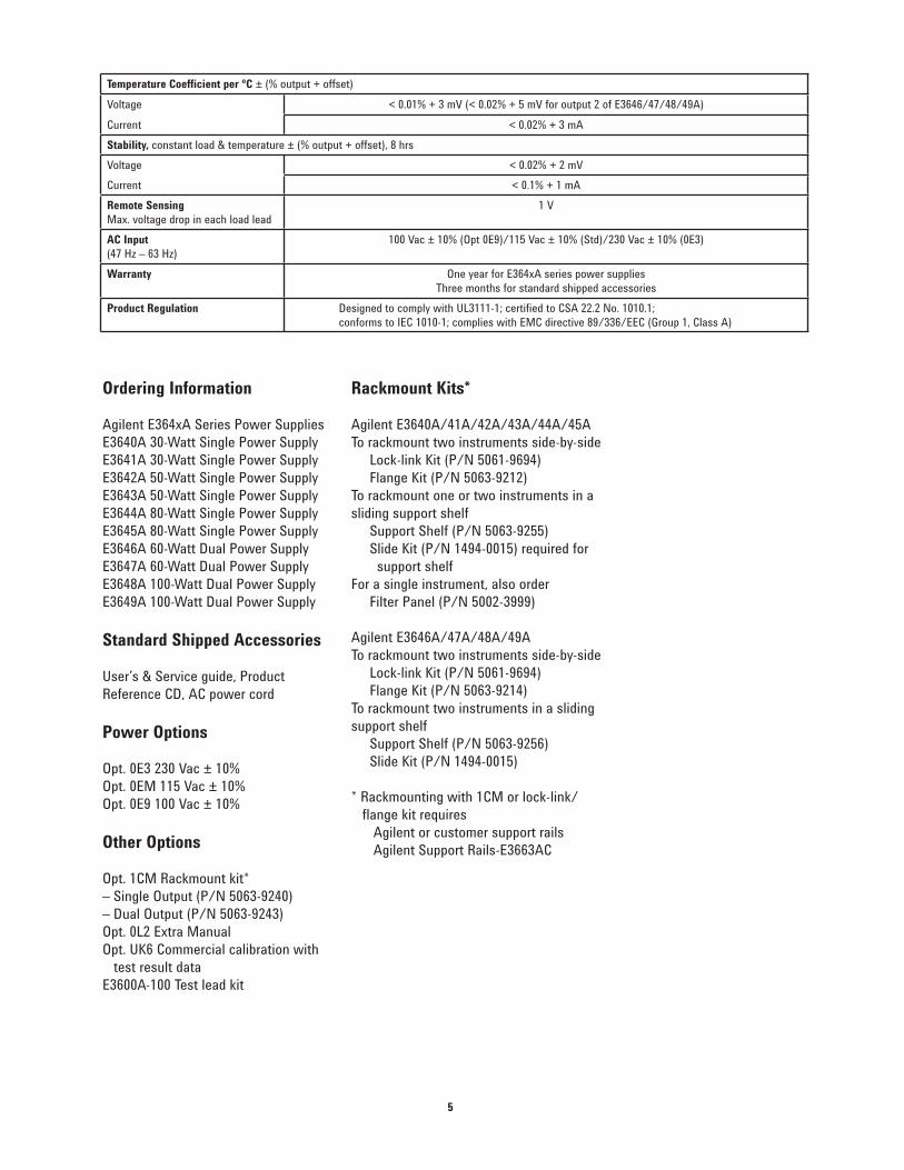
Temperature Coefficient per ºC ± (% output + offset)
Voltage < 0.01% + 3 mV (< 0.02% + 5 mV for output 2 of E3646/47/48/49A)
Current < 0.02% + 3 mA
Stability, constant load & temperature ± (% output + offset), 8 hrs
Voltage < 0.02% + 2 mV
Current < 0.1% + 1 mA
Remote Sensing
Max. voltage drop in each load lead
1 V
AC Input
(47 Hz – 63 Hz)
100 Vac ± 10% (Opt 0E9)/115 Vac ± 10% (Std)/230 Vac ± 10% (0E3)
Warranty One year for E364xA series power supplies
Three months for standard shipped accessories
Product Regulation Designed to comply with UL3111-1; certified to CSA 22.2 No. 1010.1;
conforms to IEC 1010-1; complies with EMC directive 89/336/EEC (Group 1, Class A)
Ordering Information
Agilent E364xA Series Power Supplies
E3640A 30-Watt Single Power Supply
E3641A 30-Watt Single Power Supply
E3642A 50-Watt Single Power Supply
E3643A 50-Watt Single Power Supply
E3644A 80-Watt Single Power Supply
E3645A 80-Watt Single Power Supply
E3646A 60-Watt Dual Power Supply
E3647A 60-Watt Dual Power Supply
E3648A 100-Watt Dual Power Supply
E3649A 100-Watt Dual Power Supply
Standard Shipped Accessories
User’s & Service guide, Product
Reference CD, AC power cord
Power Options
Opt. 0E3 230 Vac ± 10%
Opt. 0EM 115 Vac ± 10%
Opt. 0E9 100 Vac ± 10%
Other Options
Opt. 1CM Rackmount kit*
– Single Output (P/N 5063-9240)
– Dual Output (P/N 5063-9243)
Opt. 0L2 Extra Manual
Opt. UK6 Commercial calibration with
test result data
E3600A-100 Test lead kit
Rackmount Kits*
Agilent E3640A/41A/42A/43A/44A/45A
To rackmount two instruments side-by-side
Lock-link Kit (P/N 5061-9694)
Flange Kit (P/N 5063-9212)
To rackmount one or two instruments in a
sliding support shelf
Support Shelf (P/N 5063-9255)
Slide Kit (P/N 1494-0015) required for
support shelf
For a single instrument, also order
Filter Panel (P/N 5002-3999)
Agilent E3646A/47A/48A/49A
To rackmount two instruments side-by-side
Lock-link Kit (P/N 5061-9694)
Flange Kit (P/N 5063-9214)
To rackmount two instruments in a sliding
support shelf
Support Shelf (P/N 5063-9256)
Slide Kit (P/N 1494-0015)
* Rackmounting with 1CM or lock-link/
flange kit requires
Agilent or customer support rails
Agilent Support Rails-E3663AC
www.agilent.com/find/openAgilent Open simplifies the process of connecting and
programming test systems to help engineers design,
validate and manufacture electronic products. Agilent
offers open connectivity for a broad range of system-
ready instruments, open industry software, PC-standard
I/O and global support, which are combined to more
easily integrate test system development.
is the US registered trademark
of the LXI Consortium.
www.agilent.com/find/emailupdatesGet the latest information on the products and applica-
tions you select.
www.agilent.com/find/agilentdirectQuickly choose and use your test
equipment solutions with confidence.
Agilent Email Updates
Agilent Direct
Remove all doubt
Our repair and calibration services will get your equipment back to you, performing like new, when prom-ised. You will get full value out of your Agilent equipment through-out its lifetime. Your equipment will be serviced by Agilent-trained technicians using the latest factory calibration procedures, automated repair diagnostics and genuine parts. You will always have the utmost confidence in your measurements.
Agilent offers a wide range of ad-ditional expert test and measure-ment services for your equipment, including initial start-up assistance onsite education and training, as well as design, system integration, and project management.
For more information on repair andcalibration services, go to
www.agilent.com/find/removealldoubt
For more information on Agilent Technologies’ products, applications or services, please contact your local Agilent office. The com-plete list is available at:
www.agilent.com/find/contactus
Phone or FaxAmericasCanadaLatin AmericaUnited States
(877) 894-4414305 269 7500(800) 829-4444
Asia PacificAustraliaChinaHong KongIndiaJapanKoreaMalaysiaSingaporeTaiwanThailand
1 800 629 485800 810 0189800 938 6931 800 112 9290120 (421) 345080 769 08001 800 888 8481 800 375 81000800 047 8661 800 226 008
Europe & Middle EastAustriaBelgiumDenmarkFinlandFrance
GermanyIrelandIsraelItalyNetherlandsSpainSwedenSwitzerlandUnited KingdomOther European Countries:www.agilent.com/find/contactusRevised: October 6, 2008
01 36027 7157132 (0) 2 404 93 4045 70 13 15 15358 (0) 10 855 21000825 010 700**0.125 /minute
07031 464 63331890 924 204972-3-9288-504/54439 02 92 60 848431 (0) 20 547 211134 (91) 631 33000200-88 22 550800 80 53 5344 (0) 118 9276201
© Agilent Technologies, Inc. 2009Printed in USA, July 29, 20095968-7355EN
Product specifications and descriptionsin this document subject to changewithout notice.
www.agilent.com
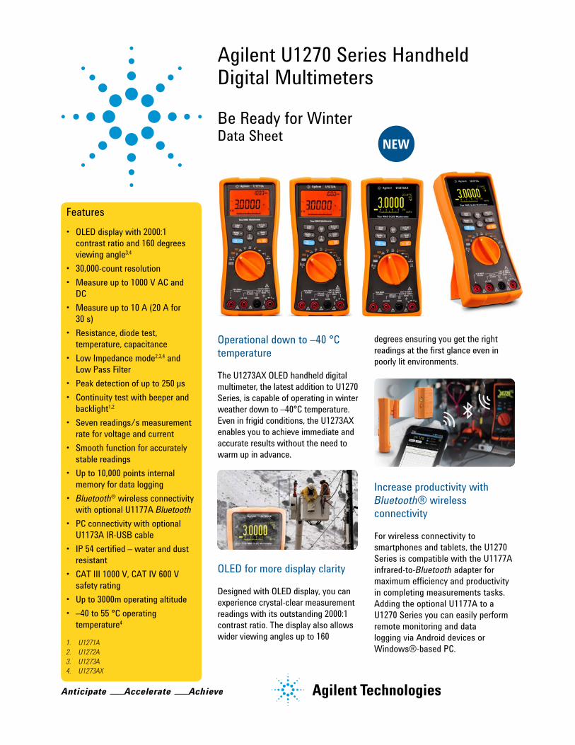
Agilent U1270 Series Handheld Digital Multimeters
Be Ready for WinterData Sheet
Features• OLED display with 2000:1
contrast ratio and 160 degrees viewing angle3,4
• 30,000-count resolution • Measure up to 1000 V AC and
DC• Measure up to 10 A (20 A for
30 s) • Resistance, diode test,
temperature, capacitance • Low Impedance mode2,3,4 and
Low Pass Filter• Peak detection of up to 250 µs• Continuity test with beeper and
backlight1,2 • Seven readings/s measurement
rate for voltage and current• Smooth function for accurately
stable readings • Up to 10,000 points internal
memory for data logging• Bluetooth® wireless connectivity
with optional U1177A Bluetooth• PC connectivity with optional
U1173A IR-USB cable• IP 54 certified – water and dust
resistant• CAT III 1000 V, CAT IV 600 V
safety rating• Up to 3000m operating altitude• –40 to 55 °C operating
temperature4
1. U1271A2. U1272A3. U1273A4. U1273AX
Operational down to –40 °C temperature
The U1273AX OLED handheld digital multimeter, the latest addition to U1270 Series, is capable of operating in winter weather down to –40°C temperature. Even in frigid conditions, the U1273AX enables you to achieve immediate and accurate results without the need to warm up in advance.
OLED for more display clarity
Designed with OLED display, you can experience crystal-clear measurement readings with its outstanding 2000:1 contrast ratio. The display also allows wider viewing angles up to 160
degrees ensuring you get the right readings at the first glance even in poorly lit environments.
Increase productivity with Bluetooth® wireless connectivity
For wireless connectivity to smartphones and tablets, the U1270 Series is compatible with the U1177A infrared-to-Bluetooth adapter for maximum efficiency and productivity in completing measurements tasks. Adding the optional U1177A to a U1270 Series you can easily perform remote monitoring and data logging via Android devices or Windows®-based PC.
NEW
2
Key Functions
Water and dust resistance (IP54)
The series’ tightly sealed design helps protect against water, dust and damage. Each handheld DMM is certified with IP 54 ratings so that you can carry out tests and measurements with confidence, even in harsh working conditions.
Operational up to 3000 meters altitude
For high altitude applications such as wind farm maintenance, you can measure with confidence using the U1270 Series, capable of measuring up to 3000 meters above sea level.
High measurement rate at seven readings per second for Voltage and Current
You can detect even the slightest change in your sensitive signals (Voltage and Current) with its high measurement rate capability. By clicking the resettable smooth function button, you may customize the readings’ sensitivity suitable for various tests.
Visual alert for continuity test (for U1271A and U1272A only)
Continuity detection in noisy and dark environments is made easy with U1270 Series’ loud beeper and flashing backlight that indicates continuity and thus improves safety.
Up to 10,000 recording points for manual, auto and event logging
Record measurements on-the-go and transfer data to PC conveniently with the huge internal memory of up to 10,000 recording points. The GUI Data Logging software and optional U1173A IR-USB cable are required to transfer data or perform real time data logging on a PC.
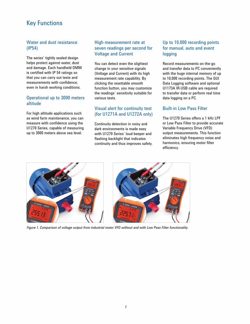
Built-in Low Pass Filter
The U1270 Series offers a 1 kHz LPF or Low Pass Filter to provide accurate Variable Frequency Drive (VFD) output measurements. This function eliminates high frequency noise and harmonics, ensuring motor filter efficiency.
Figure1.ComparisonofvoltageoutputfromindustrialmotorVFDwithoutandwithLowPassFilterfunctionality.
3
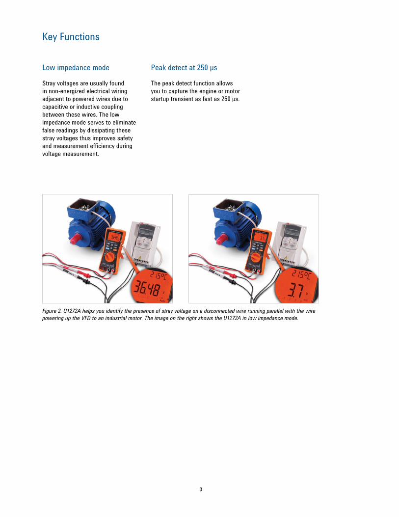
Figure2.U1272AhelpsyouidentifythepresenceofstrayvoltageonadisconnectedwirerunningparallelwiththewirepoweringuptheVFDtoanindustrialmotor.TheimageontherightshowstheU1272Ainlowimpedancemode.
Low impedance mode
Stray voltages are usually found in non-energized electrical wiring adjacent to powered wires due to capacitive or inductive coupling between these wires. The low impedance mode serves to eliminate false readings by dissipating these stray voltages thus improves safety and measurement efficiency during voltage measurement.
Peak detect at 250 µs
The peak detect function allows you to capture the engine or motor startup transient as fast as 250 µs.
Key Functions
4
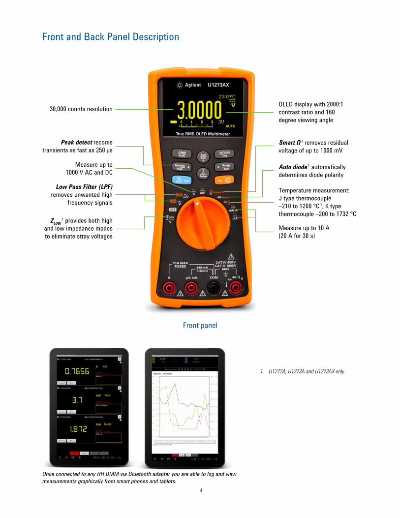
Front and Back Panel Description
OLED display with 2000:1 contrast ratio and 160 degree viewing angle
Smart Ω 1 removes residual voltage of up to 1000 mV
Auto diode 1 automatically determines diode polarity
Temperature measurement: J type thermocouple –210 to 1200 °C 1, K type thermocouple –200 to 1732 °C
ZLOW 1 provides both high
and low impedance modes to eliminate stray voltages
Measure up to 1000 V AC and DC
Low Pass Filter (LPF) removes unwanted high
frequency signals
Measure up to 10 A (20 A for 30 s)
Front panel
1. U1272A, U1273A and U1273AX only
30,000 counts resolution
Peak detect records transients as fast as 250 μs
OnceconnectedtoanyHHDMMviaBluetoothadapteryouareabletologandviewmeasurementsgraphicallyfromsmartphonesandtablets.
5
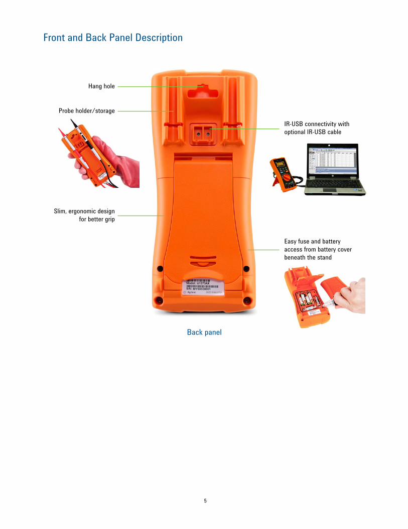
Front and Back Panel Description
Back panel
Probe holder/storage
IR-USB connectivity with optional IR-USB cable
Hang hole
Slim, ergonomic design for better grip
Easy fuse and battery access from battery cover beneath the stand

6
Choose Among These Four Models
Di U1271A U1272A U1273A U1273AXBasic FeaturesDisplay resolution 30,000 counts 30,000 counts 30,000 counts 30,000 countsDisplay LCD LCD OLED OLEDBacklight Yes Yes N/A N/ATrue RMS AC AC + DC AC + DC AC + DCMeasurementsVoltage Up to 1000 V AC, DC Up to 1000 V AC, DC Up to 1000 V AC, DC Up to 1000 V AC, DCBasic dcV accuracy 0.05% + 2 counts 0.05% + 2 counts 0.05% + 2 counts 0.05% + 2 counts
Current Up to 10 A (20 A for 30 s)
Up to 10 A (20 A for 30 s)
Up to 10 A (20 A for 30 s)
Up to 10 A (20 A for 30 s)
Resistance Up to 100 MΩ Up to 300 MΩ Up to 300 MΩ Up to 300 MΩ
Other measurementsFrequency, capacitance, temperature, continuity,
diode test
Frequency, capacitance, temperature, continuity,
diode test
Frequency, capacitance, temperature, continuity,
diode test
Frequency, capacitance, temperature, continuity,
diode testAC bandwidth 20 kHz 100 kHz 100 kHz 100 kHz
Low pass filterYes Yes Yes Yes
Low impedance mode — Yes Yes YesSmart Ohm — Yes Yes YesSafety and RegulatoryOver-voltage safety protection
CAT III 1000 V, CAT IV 600 V
CAT III 1000 V, CAT IV 600 V
CAT III 1000 V, CAT IV 600 V
CAT III 1000 V, CAT IV 600 V
GeneralLogging memory 200 points 10,000 points 10,000 points 10,000 points
Connectivity Optional IR-USB and Bluetooth
Optional IR-USB and Bluetooth
Optional IR-USB and Bluetooth
Optional IR-USB and Bluetooth
Operating temperature –20 to 55 °C –20 to 55 °C –20 to 55 °C –40 to 55 °CAltitude 3000 meters 3000 meters 3000 meters 3000 metersWater and dust ingress protection IP 54 IP 54 IP 54 IP 54
Battery life Up to 300 hours 4X AAA Alkaline
Up to 300 hours 4X AAA Alkaline
Up to 60 hours 4X AAA Alkaline
Up to 100 hours 4X AAA Lithium
Warranty 3 years 3 years 3 years 3 years
7
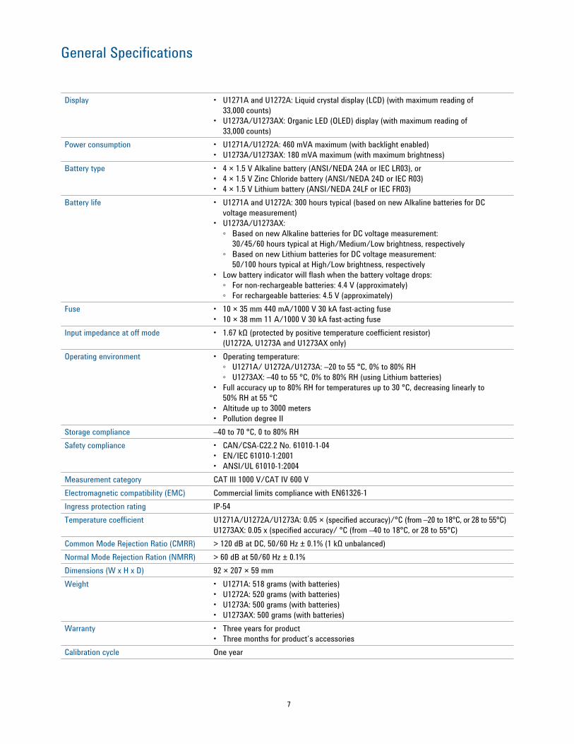
General Specifications
Display • U1271A and U1272A: Liquid crystal display (LCD) (with maximum reading of 33,000 counts)
• U1273A/U1273AX: Organic LED (OLED) display (with maximum reading of 33,000 counts)
Power consumption • U1271A/U1272A: 460 mVA maximum (with backlight enabled)• U1273A/U1273AX: 180 mVA maximum (with maximum brightness)
Battery type • 4 × 1.5 V Alkaline battery (ANSI/NEDA 24A or IEC LR03), or • 4 × 1.5 V Zinc Chloride battery (ANSI/NEDA 24D or IEC R03)• 4 × 1.5 V Lithium battery (ANSI/NEDA 24LF or IEC FR03)
Battery life • U1271A and U1272A: 300 hours typical (based on new Alkaline batteries for DC voltage measurement)
• U1273A/U1273AX: Based on new Alkaline batteries for DC voltage measurement:
30/45/60 hours typical at High/Medium/Low brightness, respectively Based on new Lithium batteries for DC voltage measurement:
50/100 hours typical at High/Low brightness, respectively• Low battery indicator will flash when the battery voltage drops:
For non-rechargeable batteries: 4.4 V (approximately) For rechargeable batteries: 4.5 V (approximately)
Fuse • 10 × 35 mm 440 mA/1000 V 30 kA fast-acting fuse• 10 × 38 mm 11 A/1000 V 30 kA fast-acting fuse
Input impedance at off mode • 1.67 kΩ (protected by positive temperature coefficient resistor) (U1272A, U1273A and U1273AX only)
Operating environment • Operating temperature: U1271A/ U1272A/U1273A: –20 to 55 °C, 0% to 80% RH U1273AX: –40 to 55 °C, 0% to 80% RH (using Lithium batteries)
• Full accuracy up to 80% RH for temperatures up to 30 °C, decreasing linearly to 50% RH at 55 °C
• Altitude up to 3000 meters• Pollution degree II
Storage compliance –40 to 70 °C, 0 to 80% RHSafety compliance • CAN/CSA-C22.2 No. 61010-1-04
• EN/IEC 61010-1:2001• ANSI/UL 61010-1:2004
Measurement category CAT III 1000 V/CAT IV 600 VElectromagnetic compatibility (EMC) Commercial limits compliance with EN61326-1Ingress protection rating IP-54Temperature coefficient U1271A/U1272A/U1273A: 0.05 × (specified accuracy)/°C (from –20 to 18°C, or 28 to 55°C)
U1273AX: 0.05 x (specified accuracy/ °C (from –40 to 18°C, or 28 to 55°C) Common Mode Rejection Ratio (CMRR) > 120 dB at DC, 50/60 Hz ± 0.1% (1 kΩ unbalanced)Normal Mode Rejection Ration (NMRR) > 60 dB at 50/60 Hz ± 0.1%Dimensions (W x H x D) 92 × 207 × 59 mmWeight • U1271A: 518 grams (with batteries)
• U1272A: 520 grams (with batteries)• U1273A: 500 grams (with batteries)• U1273AX: 500 grams (with batteries)
Warranty • Three years for product• Three months for product’s accessories
Calibration cycle One year
8
Specification Assumptions
• Accuracy is given as ±(% of reading + counts of least significant digit) at 23 °C ± 5 °C, with relative humidity less than 80% RH.
• AC V and AC μA/mA/A specifications are AC coupled, true RMS and are valid from 5% of range to 100% of range.
• The crest factor may be up to 3.0 at full scale except for the 1000 V range where it is 1.5 at full scale.
• For non-sinusoidal waveforms, add (2% reading + 2% full scale) typical, for crest factors up to 3.
• After ZLOW voltage measurements, wait at least 20 minutes for thermal impact to cool before proceeding with any other measurement.
9
Electrical Specifications
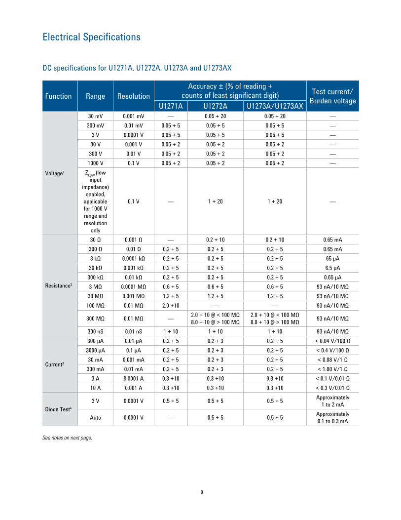
DC specifications for U1271A, U1272A, U1273A and U1273AX
Function Range ResolutionAccuracy ± (% of reading +
counts of least significant digit) Test current/Burden voltageU1271A U1272A U1273A/U1273AX
Voltage1
30 mV 0.001 mV — 0.05 + 20 0.05 + 20 —300 mV 0.01 mV 0.05 + 5 0.05 + 5 0.05 + 5 —
3 V 0.0001 V 0.05 + 5 0.05 + 5 0.05 + 5 —30 V 0.001 V 0.05 + 2 0.05 + 2 0.05 + 2 —300 V 0.01 V 0.05 + 2 0.05 + 2 0.05 + 2 —1000 V 0.1 V 0.05 + 2 0.05 + 2 0.05 + 2 —
ZLOW (low input
impedance) enabled,
applicable for 1000 V range and resolution
only
0.1 V — 1 + 20 1 + 20 —
Resistance2
30 Ω 0.001 Ω — 0.2 + 10 0.2 + 10 0.65 mA300 Ω 0.01 Ω 0.2 + 5 0.2 + 5 0.2 + 5 0.65 mA3 kΩ 0.0001 kΩ 0.2 + 5 0.2 + 5 0.2 + 5 65 µA30 kΩ 0.001 kΩ 0.2 + 5 0.2 + 5 0.2 + 5 6.5 µA300 kΩ 0.01 kΩ 0.2 + 5 0.2 + 5 0.2 + 5 0.65 µA3 MΩ 0.0001 MΩ 0.6 + 5 0.6 + 5 0.6 + 5 93 nA/10 MΩ30 MΩ 0.001 MΩ 1.2 + 5 1.2 + 5 1.2 + 5 93 nA/10 MΩ100 MΩ 0.01 MΩ 2.0 +10 — — 93 nA/10 MΩ
300 MΩ 0.01 MΩ — 2.0 + 10 @ < 100 MΩ 8.0 + 10 @ > 100 MΩ
2.0 + 10 @ < 100 MΩ 8.0 + 10 @ > 100 MΩ 93 nA/10 MΩ
300 nS 0.01 nS 1 + 10 1 + 10 1 + 10 93 nA/10 MΩ
Current3
300 µA 0.01 µA 0.2 + 5 0.2 + 3 0.2 + 5 < 0.04 V/100 Ω3000 µA 0.1 µA 0.2 + 5 0.2 + 3 0.2 + 5 < 0.4 V/100 Ω30 mA 0.001 mA 0.2 + 5 0.2 + 3 0.2 + 5 < 0.08 V/1 Ω300 mA 0.01 mA 0.2 + 5 0.2 + 3 0.2 + 5 < 1.00 V/1 Ω
3 A 0.0001 A 0.3 +10 0.3 +10 0.3 +10 < 0.1 V/0.01 Ω10 A 0.001 A 0.3 +10 0.3 +10 0.3 +10 < 0.3 V/0.01 Ω
Diode Test4
3 V 0.0001 V 0.5 + 5 0.5 + 5 0.5 + 5 Approximately 1 to 2 mA
Auto 0.0001 V — 0.5 + 5 0.5 + 5 Approximately 0.1 to 0.3 mA
See notes on next page.
10
Electrical Specifications
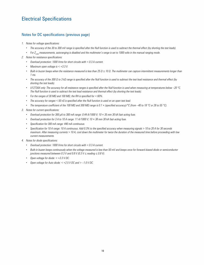
Notes for DC specifications (previous page)
1. Notes for voltage specifications: • The accuracy of the 30 to 300 mV range is specified after the Null function is used to subtract the thermal effect (by shorting the test leads).• For ZLOW measurements, autoranging is disabled and the multimeter’s range is set to 1000 volts in the manual ranging mode.
2. Notes for resistance specifications:• Overload protection: 1000 Vrms for short circuits with < 0.3 A current. • Maximum open voltage is < +3.3 V. • Built-in buzzer beeps when the resistance measured is less than 25 Ω ± 10 Ω. The multimeter can capture intermittent measurements longer than
1 ms. • The accuracy of the 300 Ω to 3 kΩ range is specified after the Null function is used to subtract the test lead resistance and thermal effect (by
shorting the test leads). • U1273AX only: The accuracy for all resistance ranges is specified after the Null function is used when measuring at temperatures below –20 °C.
The Null function is used to subtract the test lead resistance and thermal effect (by shorting the test leads).• For the ranges of 30 MΩ and 100 MΩ, the RH is specified for < 60%. • The accuracy for ranges < 50 nS is specified after the Null function is used on an open test lead.• The temperature coefficient of the 100 MΩ and 300 MΩ range is 0.1 × (specified accuracy)/°C (from –40 to 18 °C or 28 to 55 °C).
3. Notes for current specifications: • Overload protection for 300 μA to 300 mA range: 0.44 A/1000 V; 10 × 35 mm 30 kA fast-acting fuse. • Overload protection for 3 A to 10 A range: 11 A/1000 V; 10 × 38 mm 30 kA fast-acting fuse. • Specification for 300 mA range: 440 mA continuous. • Specification for 10 A range: 10 A continuous. Add 0.3% to the specified accuracy when measuring signals > 10 to 20 A for 30 seconds
maximum. After measuring currents > 10 A, cool down the multimeter for twice the duration of the measured time before proceeding with low current measurements.
4. Notes for diode specifications:• Overload protection: 1000 Vrms for short circuits with < 0.3 A current. • Built-in buzzer beeps continuously when the voltage measured is less than 50 mV and beeps once for forward-biased diode or semiconductor
junctions measured between 0.3 V and 0.8 V (0.3 V ≤ reading ≤ 0.8 V). • Open voltage for diode: < +3.3 V DC. • Open voltage for Auto diode: < +2.5 V DC and > –1.0 V DC.
11
Electrical Specifications
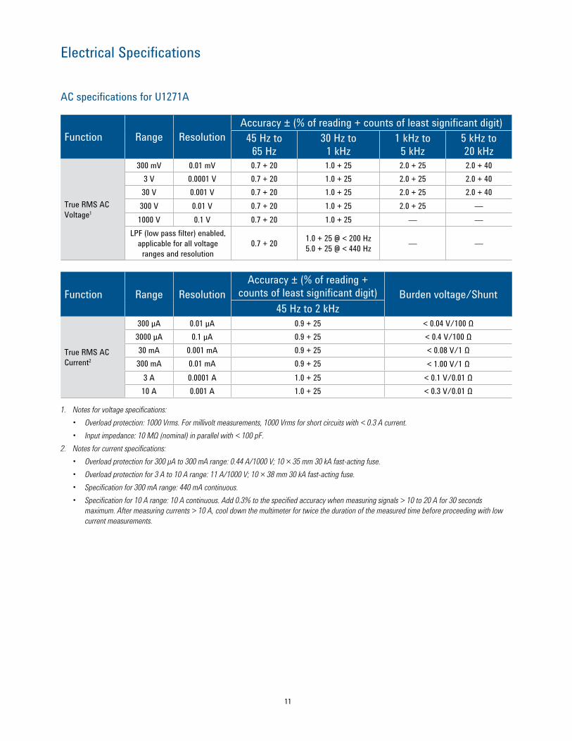
AC specifications for U1271A
Function Range ResolutionAccuracy ± (% of reading + counts of least significant digit)
45 Hz to 65 Hz
30 Hz to 1 kHz
1 kHz to 5 kHz
5 kHz to 20 kHz
True RMS AC Voltage1
300 mV 0.01 mV 0.7 + 20 1.0 + 25 2.0 + 25 2.0 + 403 V 0.0001 V 0.7 + 20 1.0 + 25 2.0 + 25 2.0 + 4030 V 0.001 V 0.7 + 20 1.0 + 25 2.0 + 25 2.0 + 40300 V 0.01 V 0.7 + 20 1.0 + 25 2.0 + 25 —1000 V 0.1 V 0.7 + 20 1.0 + 25 — —
LPF (low pass filter) enabled, applicable for all voltage
ranges and resolution0.7 + 20 1.0 + 25 @ < 200 Hz
5.0 + 25 @ < 440 Hz — —
Function Range ResolutionAccuracy ± (% of reading +
counts of least significant digit) Burden voltage/Shunt45 Hz to 2 kHz
True RMS AC Current2
300 µA 0.01 µA 0.9 + 25 < 0.04 V/100 Ω3000 µA 0.1 µA 0.9 + 25 < 0.4 V/100 Ω30 mA 0.001 mA 0.9 + 25 < 0.08 V/1 Ω300 mA 0.01 mA 0.9 + 25 < 1.00 V/1 Ω
3 A 0.0001 A 1.0 + 25 < 0.1 V/0.01 Ω10 A 0.001 A 1.0 + 25 < 0.3 V/0.01 Ω
1. Notes for voltage specifications: • Overload protection: 1000 Vrms. For millivolt measurements, 1000 Vrms for short circuits with < 0.3 A current.• Input impedance: 10 MΩ (nominal) in parallel with < 100 pF.
2. Notes for current specifications:• Overload protection for 300 μA to 300 mA range: 0.44 A/1000 V; 10 × 35 mm 30 kA fast-acting fuse. • Overload protection for 3 A to 10 A range: 11 A/1000 V; 10 × 38 mm 30 kA fast-acting fuse. • Specification for 300 mA range: 440 mA continuous. • Specification for 10 A range: 10 A continuous. Add 0.3% to the specified accuracy when measuring signals > 10 to 20 A for 30 seconds
maximum. After measuring currents > 10 A, cool down the multimeter for twice the duration of the measured time before proceeding with low current measurements.
12
Electrical Specifications
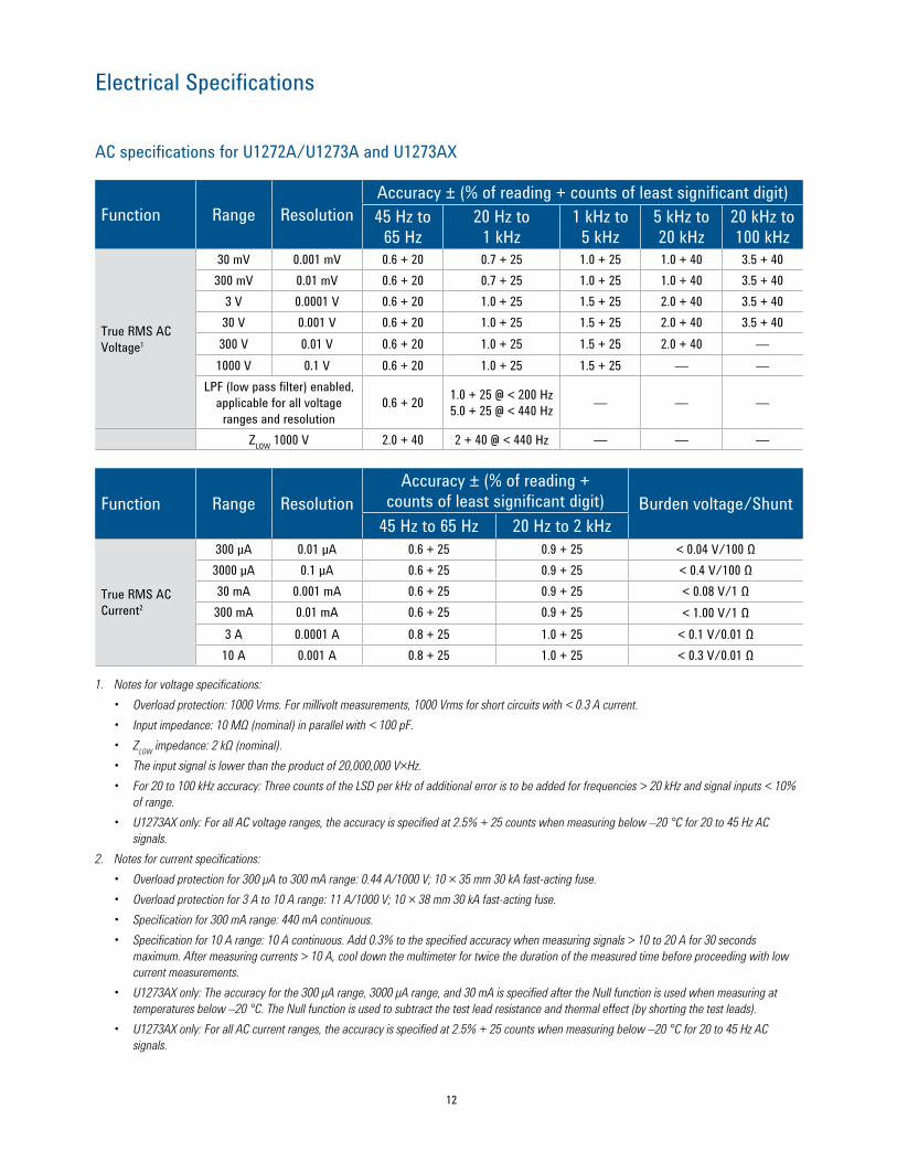
AC specifications for U1272A/U1273A and U1273AX
Function Range ResolutionAccuracy ± (% of reading + counts of least significant digit)45 Hz to
65 Hz20 Hz to
1 kHz1 kHz to
5 kHz5 kHz to 20 kHz
20 kHz to 100 kHz
True RMS AC Voltage1
30 mV 0.001 mV 0.6 + 20 0.7 + 25 1.0 + 25 1.0 + 40 3.5 + 40300 mV 0.01 mV 0.6 + 20 0.7 + 25 1.0 + 25 1.0 + 40 3.5 + 40
3 V 0.0001 V 0.6 + 20 1.0 + 25 1.5 + 25 2.0 + 40 3.5 + 4030 V 0.001 V 0.6 + 20 1.0 + 25 1.5 + 25 2.0 + 40 3.5 + 40300 V 0.01 V 0.6 + 20 1.0 + 25 1.5 + 25 2.0 + 40 —1000 V 0.1 V 0.6 + 20 1.0 + 25 1.5 + 25 — —
LPF (low pass filter) enabled, applicable for all voltage
ranges and resolution0.6 + 20 1.0 + 25 @ < 200 Hz
5.0 + 25 @ < 440 Hz — — —
ZLOW 1000 V 2.0 + 40 2 + 40 @ < 440 Hz — — —
Function Range ResolutionAccuracy ± (% of reading +
counts of least significant digit) Burden voltage/Shunt45 Hz to 65 Hz 20 Hz to 2 kHz
True RMS AC Current2
300 µA 0.01 µA 0.6 + 25 0.9 + 25 < 0.04 V/100 Ω3000 µA 0.1 µA 0.6 + 25 0.9 + 25 < 0.4 V/100 Ω30 mA 0.001 mA 0.6 + 25 0.9 + 25 < 0.08 V/1 Ω300 mA 0.01 mA 0.6 + 25 0.9 + 25 < 1.00 V/1 Ω
3 A 0.0001 A 0.8 + 25 1.0 + 25 < 0.1 V/0.01 Ω10 A 0.001 A 0.8 + 25 1.0 + 25 < 0.3 V/0.01 Ω
1. Notes for voltage specifications: • Overload protection: 1000 Vrms. For millivolt measurements, 1000 Vrms for short circuits with < 0.3 A current.• Input impedance: 10 MΩ (nominal) in parallel with < 100 pF.• ZLOW impedance: 2 kΩ (nominal).• The input signal is lower than the product of 20,000,000 V×Hz.• For 20 to 100 kHz accuracy: Three counts of the LSD per kHz of additional error is to be added for frequencies > 20 kHz and signal inputs < 10%
of range.• U1273AX only: For all AC voltage ranges, the accuracy is specified at 2.5% + 25 counts when measuring below –20 °C for 20 to 45 Hz AC
signals.2. Notes for current specifications:• Overload protection for 300 μA to 300 mA range: 0.44 A/1000 V; 10 × 35 mm 30 kA fast-acting fuse. • Overload protection for 3 A to 10 A range: 11 A/1000 V; 10 × 38 mm 30 kA fast-acting fuse. • Specification for 300 mA range: 440 mA continuous. • Specification for 10 A range: 10 A continuous. Add 0.3% to the specified accuracy when measuring signals > 10 to 20 A for 30 seconds
maximum. After measuring currents > 10 A, cool down the multimeter for twice the duration of the measured time before proceeding with low current measurements.
• U1273AX only: The accuracy for the 300 μA range, 3000 μA range, and 30 mA is specified after the Null function is used when measuring at temperatures below –20 °C. The Null function is used to subtract the test lead resistance and thermal effect (by shorting the test leads).
• U1273AX only: For all AC current ranges, the accuracy is specified at 2.5% + 25 counts when measuring below –20 °C for 20 to 45 Hz AC signals.
13
Electrical Specifications
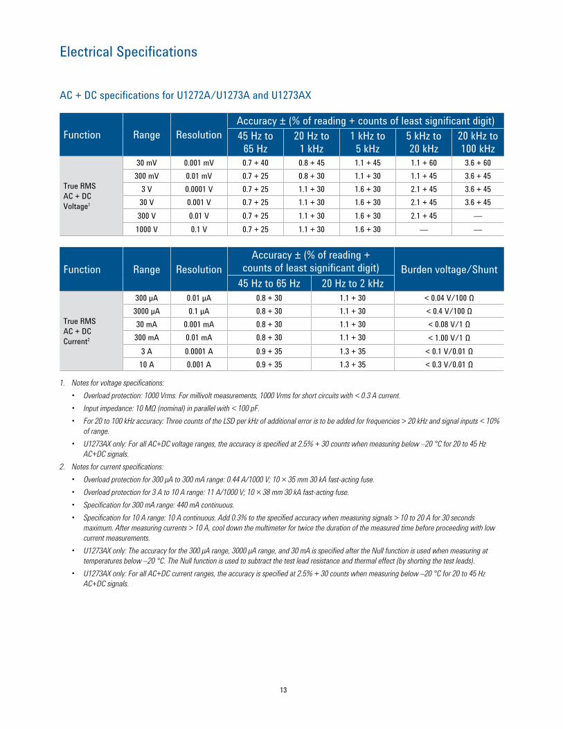
AC + DC specifications for U1272A/U1273A and U1273AX
Function Range ResolutionAccuracy ± (% of reading + counts of least significant digit)45 Hz to
65 Hz20 Hz to
1 kHz1 kHz to
5 kHz5 kHz to 20 kHz
20 kHz to 100 kHz
True RMS AC + DC Voltage1
30 mV 0.001 mV 0.7 + 40 0.8 + 45 1.1 + 45 1.1 + 60 3.6 + 60300 mV 0.01 mV 0.7 + 25 0.8 + 30 1.1 + 30 1.1 + 45 3.6 + 45
3 V 0.0001 V 0.7 + 25 1.1 + 30 1.6 + 30 2.1 + 45 3.6 + 4530 V 0.001 V 0.7 + 25 1.1 + 30 1.6 + 30 2.1 + 45 3.6 + 45300 V 0.01 V 0.7 + 25 1.1 + 30 1.6 + 30 2.1 + 45 —1000 V 0.1 V 0.7 + 25 1.1 + 30 1.6 + 30 — —
Function Range ResolutionAccuracy ± (% of reading +
counts of least significant digit) Burden voltage/Shunt45 Hz to 65 Hz 20 Hz to 2 kHz
True RMS AC + DC Current2
300 µA 0.01 µA 0.8 + 30 1.1 + 30 < 0.04 V/100 Ω3000 µA 0.1 µA 0.8 + 30 1.1 + 30 < 0.4 V/100 Ω30 mA 0.001 mA 0.8 + 30 1.1 + 30 < 0.08 V/1 Ω300 mA 0.01 mA 0.8 + 30 1.1 + 30 < 1.00 V/1 Ω
3 A 0.0001 A 0.9 + 35 1.3 + 35 < 0.1 V/0.01 Ω10 A 0.001 A 0.9 + 35 1.3 + 35 < 0.3 V/0.01 Ω
1. Notes for voltage specifications: • Overload protection: 1000 Vrms. For millivolt measurements, 1000 Vrms for short circuits with < 0.3 A current.• Input impedance: 10 MΩ (nominal) in parallel with < 100 pF.• For 20 to 100 kHz accuracy: Three counts of the LSD per kHz of additional error is to be added for frequencies > 20 kHz and signal inputs < 10%
of range.• U1273AX only: For all AC+DC voltage ranges, the accuracy is specified at 2.5% + 30 counts when measuring below –20 °C for 20 to 45 Hz
AC+DC signals.2. Notes for current specifications:• Overload protection for 300 μA to 300 mA range: 0.44 A/1000 V; 10 × 35 mm 30 kA fast-acting fuse. • Overload protection for 3 A to 10 A range: 11 A/1000 V; 10 × 38 mm 30 kA fast-acting fuse. • Specification for 300 mA range: 440 mA continuous. • Specification for 10 A range: 10 A continuous. Add 0.3% to the specified accuracy when measuring signals > 10 to 20 A for 30 seconds
maximum. After measuring currents > 10 A, cool down the multimeter for twice the duration of the measured time before proceeding with low current measurements.
• U1273AX only: The accuracy for the 300 μA range, 3000 μA range, and 30 mA is specified after the Null function is used when measuring at temperatures below –20 °C. The Null function is used to subtract the test lead resistance and thermal effect (by shorting the test leads).
• U1273AX only: For all AC+DC current ranges, the accuracy is specified at 2.5% + 30 counts when measuring below –20 °C for 20 to 45 Hz AC+DC signals.
14
Electrical Specifications
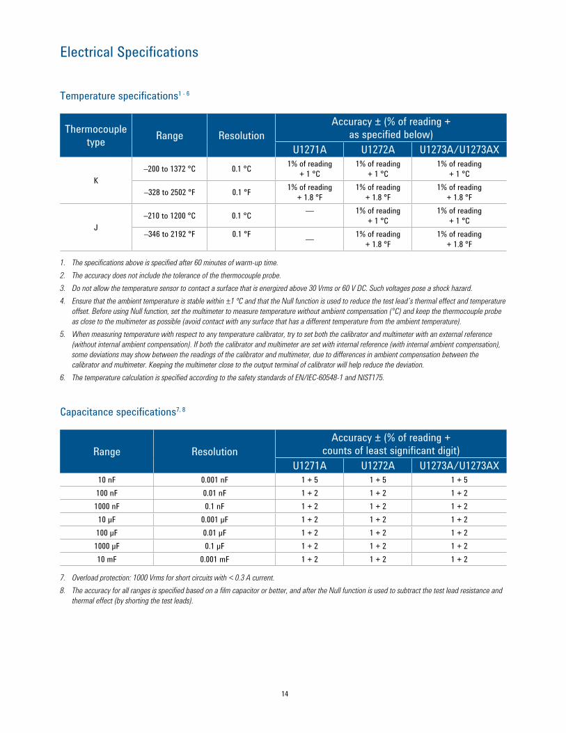
Temperature specifications1 - 6
Thermocouple type Range Resolution
Accuracy ± (% of reading + as specified below)
U1271A U1272A U1273A/U1273AX
K–200 to 1372 °C 0.1 °C 1% of reading
+ 1 °C1% of reading
+ 1 °C1% of reading
+ 1 °C
–328 to 2502 °F 0.1 °F 1% of reading + 1.8 °F
1% of reading + 1.8 °F
1% of reading + 1.8 °F
J–210 to 1200 °C 0.1 °C — 1% of reading
+ 1 °C1% of reading
+ 1 °C–346 to 2192 °F 0.1 °F — 1% of reading
+ 1.8 °F1% of reading
+ 1.8 °F
1. The specifications above is specified after 60 minutes of warm-up time.2. The accuracy does not include the tolerance of the thermocouple probe.3. Do not allow the temperature sensor to contact a surface that is energized above 30 Vrms or 60 V DC. Such voltages pose a shock hazard.4. Ensure that the ambient temperature is stable within ±1 ºC and that the Null function is used to reduce the test lead’s thermal effect and temperature
offset. Before using Null function, set the multimeter to measure temperature without ambient compensation (°C) and keep the thermocouple probe as close to the multimeter as possible (avoid contact with any surface that has a different temperature from the ambient temperature).
5. When measuring temperature with respect to any temperature calibrator, try to set both the calibrator and multimeter with an external reference (without internal ambient compensation). If both the calibrator and multimeter are set with internal reference (with internal ambient compensation), some deviations may show between the readings of the calibrator and multimeter, due to differences in ambient compensation between the calibrator and multimeter. Keeping the multimeter close to the output terminal of calibrator will help reduce the deviation.
6. The temperature calculation is specified according to the safety standards of EN/IEC-60548-1 and NIST175.
Capacitance specifications7, 8
Range ResolutionAccuracy ± (% of reading +
counts of least significant digit)U1271A U1272A U1273A/U1273AX
10 nF 0.001 nF 1 + 5 1 + 5 1 + 5100 nF 0.01 nF 1 + 2 1 + 2 1 + 21000 nF 0.1 nF 1 + 2 1 + 2 1 + 210 μF 0.001 μF 1 + 2 1 + 2 1 + 2100 μF 0.01 μF 1 + 2 1 + 2 1 + 21000 μF 0.1 μF 1 + 2 1 + 2 1 + 210 mF 0.001 mF 1 + 2 1 + 2 1 + 2
7. Overload protection: 1000 Vrms for short circuits with < 0.3 A current.8. The accuracy for all ranges is specified based on a film capacitor or better, and after the Null function is used to subtract the test lead resistance and
thermal effect (by shorting the test leads).
15
Electrical Specifications
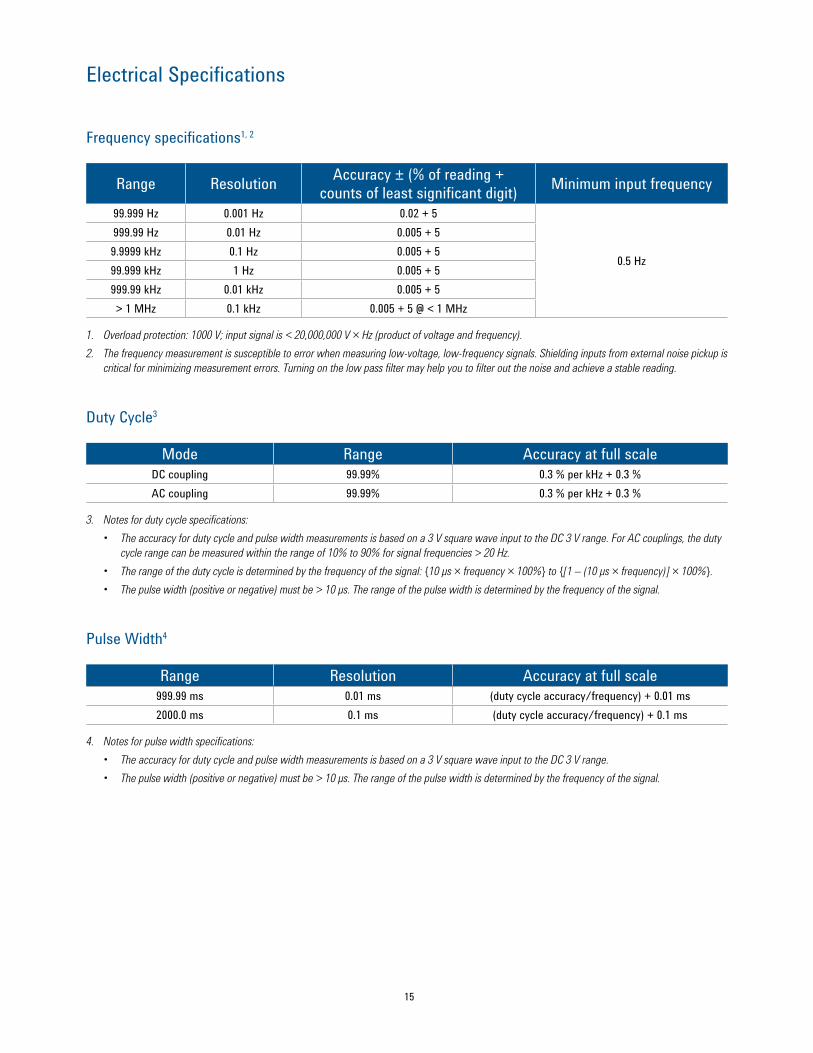
Frequency specifications1, 2
Range Resolution Accuracy ± (% of reading + counts of least significant digit) Minimum input frequency
99.999 Hz 0.001 Hz 0.02 + 5
0.5 Hz
999.99 Hz 0.01 Hz 0.005 + 59.9999 kHz 0.1 Hz 0.005 + 599.999 kHz 1 Hz 0.005 + 5999.99 kHz 0.01 kHz 0.005 + 5> 1 MHz 0.1 kHz 0.005 + 5 @ < 1 MHz
1. Overload protection: 1000 V; input signal is < 20,000,000 V × Hz (product of voltage and frequency).2. The frequency measurement is susceptible to error when measuring low-voltage, low-frequency signals. Shielding inputs from external noise pickup is
critical for minimizing measurement errors. Turning on the low pass filter may help you to filter out the noise and achieve a stable reading.
Duty Cycle3
Mode Range Accuracy at full scaleDC coupling 99.99% 0.3 % per kHz + 0.3 %AC coupling 99.99% 0.3 % per kHz + 0.3 %
3. Notes for duty cycle specifications:• The accuracy for duty cycle and pulse width measurements is based on a 3 V square wave input to the DC 3 V range. For AC couplings, the duty
cycle range can be measured within the range of 10% to 90% for signal frequencies > 20 Hz.• The range of the duty cycle is determined by the frequency of the signal: 10 μs × frequency × 100% to [1 – (10 μs × frequency)] × 100%.• The pulse width (positive or negative) must be > 10 μs. The range of the pulse width is determined by the frequency of the signal.
Pulse Width4
Range Resolution Accuracy at full scale999.99 ms 0.01 ms (duty cycle accuracy/frequency) + 0.01 ms2000.0 ms 0.1 ms (duty cycle accuracy/frequency) + 0.1 ms
4. Notes for pulse width specifications:• The accuracy for duty cycle and pulse width measurements is based on a 3 V square wave input to the DC 3 V range.• The pulse width (positive or negative) must be > 10 μs. The range of the pulse width is determined by the frequency of the signal.
16
Electrical Specifications
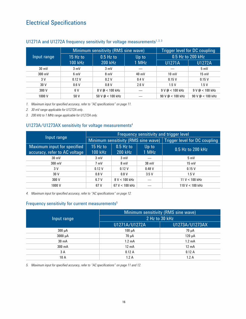
U1271A and U1272A frequency sensitivity for voltage measurements1, 2, 3
Input rangeMinimum sensitivity (RMS sine wave) Trigger level for DC coupling
15 Hz to 100 kHz
0.5 Hz to 200 kHz
Up to 1 MHz
0.5 Hz to 200 kHzU1271A U1272A
30 mV 3 mV 3 mV — — 5 mV300 mV 6 mV 8 mV 40 mV 10 mV 15 mV
3 V 0.12 V 0.2 V 0.4 V 0.15 V 0.15 V30 V 0.6 V 0.8 V 2.6 V 1.5 V 1.5 V300 V 6 V 8 V @ < 100 kHz — 9 V @ < 100 kHz 9 V @ < 100 kHz1000 V 50 V 50 V @ < 100 kHz — 90 V @ < 100 kHz 90 V @ < 100 kHz
1. Maximum input for specified accuracy, refer to “AC specifications” on page 11.2. 30 mV range applicable for U1272A only. 3. 200 kHz to 1 MHz range applicable for U1272A only.
U1273A/U1273AX sensitivity for voltage measurements4
Input range Frequency sensitivity and trigger levelMinimum sensitivity (RMS sine wave) Trigger level for DC coupling
Maximum input for specified accuracy, refer to AC voltage
15 Hz to 100 kHz
0.5 Hz to 200 kHz
Up to 1 MHz 0.5 Hz to 200 kHz
30 mV 3 mV 3 mV — 5 mV300 mV 7 mV 8 mV 38 mV 15 mV
3 V 0.12 V 0.12 V 0.48 V 0.15 V30 V 0.8 V 0.8 V 3.5 V 1.5 V300 V 6.7 V 8 V < 100 kHz — 11 V < 100 kHz1000 V 67 V 67 V < 100 kHz — 110 V < 100 kHz
4. Maximum input for specified accuracy, refer to “AC specifications” on page 12.
Frequency sensitivity for current measurements5
Input rangeMinimum sensitivity (RMS sine wave)
2 Hz to 30 kHzU1271A/U1272A U1273A/U1273AX
300 µA 100 µA 70 μA3000 µA 70 µA 120 μA30 mA 1.2 mA 1.2 mA300 mA 12 mA 12 mA
3 A 0.12 A 0.12 A10 A 1.2 A 1.2 A
5. Maximum input for specified accuracy, refer to “AC specifications” on page 11 and 12.
17
Electrical Specifications
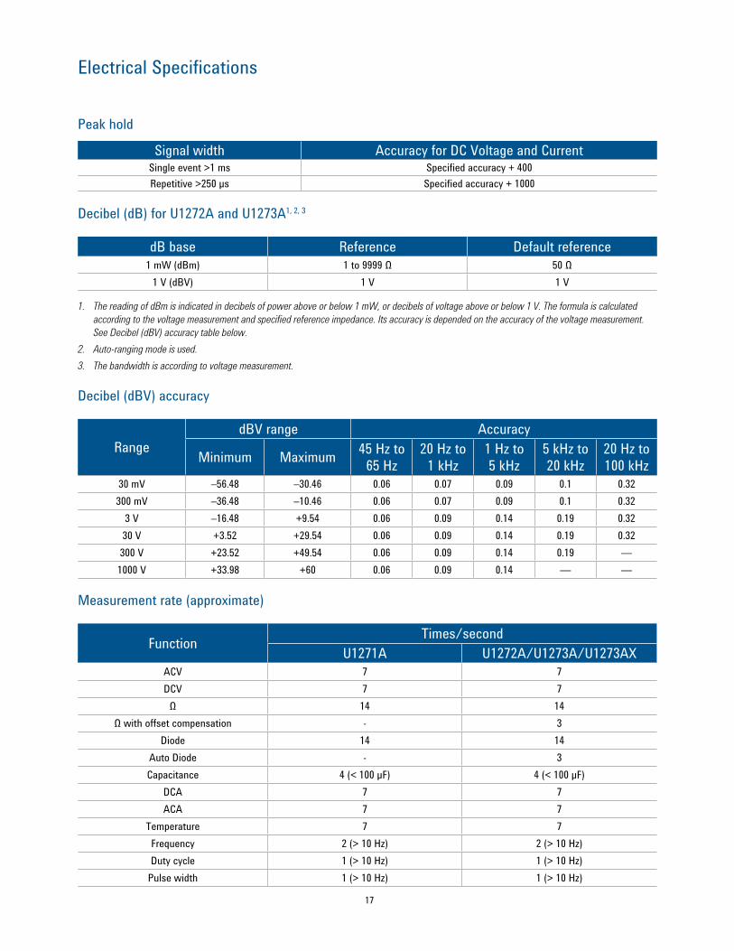
Peak hold
Signal width Accuracy for DC Voltage and CurrentSingle event >1 ms Specified accuracy + 400Repetitive >250 µs Specified accuracy + 1000
Decibel (dB) for U1272A and U1273A1, 2, 3
dB base Reference Default reference1 mW (dBm) 1 to 9999 Ω 50 Ω
1 V (dBV) 1 V 1 V
1. The reading of dBm is indicated in decibels of power above or below 1 mW, or decibels of voltage above or below 1 V. The formula is calculated according to the voltage measurement and specified reference impedance. Its accuracy is depended on the accuracy of the voltage measurement. See Decibel (dBV) accuracy table below.
2. Auto-ranging mode is used.3. The bandwidth is according to voltage measurement.
Decibel (dBV) accuracy
RangedBV range Accuracy
Minimum Maximum 45 Hz to 65 Hz
20 Hz to 1 kHz
1 Hz to 5 kHz
5 kHz to 20 kHz
20 Hz to 100 kHz
30 mV –56.48 –30.46 0.06 0.07 0.09 0.1 0.32300 mV –36.48 –10.46 0.06 0.07 0.09 0.1 0.32
3 V –16.48 +9.54 0.06 0.09 0.14 0.19 0.3230 V +3.52 +29.54 0.06 0.09 0.14 0.19 0.32300 V +23.52 +49.54 0.06 0.09 0.14 0.19 —1000 V +33.98 +60 0.06 0.09 0.14 — —
Measurement rate (approximate)
Function Times/secondU1271A U1272A/U1273A/U1273AX
ACV 7 7DCV 7 7
Ω 14 14Ω with offset compensation - 3
Diode 14 14Auto Diode - 3Capacitance 4 (< 100 µF) 4 (< 100 µF)
DCA 7 7ACA 7 7
Temperature 7 7Frequency 2 (> 10 Hz) 2 (> 10 Hz)Duty cycle 1 (> 10 Hz) 1 (> 10 Hz)
Pulse width 1 (> 10 Hz) 1 (> 10 Hz)
18
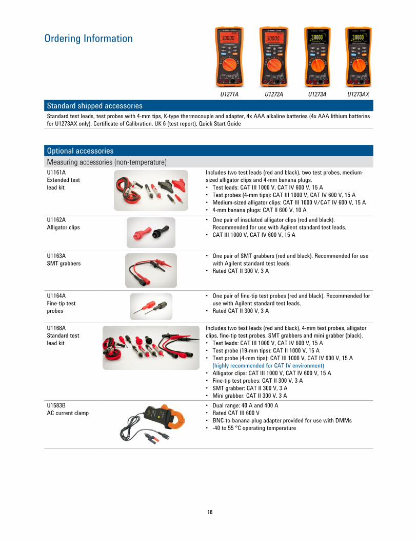
Ordering Information
Standard shipped accessoriesStandard test leads, test probes with 4-mm tips, K-type thermocouple and adapter, 4x AAA alkaline batteries (4x AAA lithium batteries for U1273AX only), Certificate of Calibration, UK 6 (test report), Quick Start Guide
Optional accessoriesMeasuring accessories (non-temperature)U1161A Extended test lead kit
Includes two test leads (red and black), two test probes, medium-sized alligator clips and 4-mm banana plugs.• Test leads: CAT III 1000 V, CAT IV 600 V, 15 A• Test probes (4-mm tips): CAT III 1000 V, CAT IV 600 V, 15 A• Medium-sized alligator clips: CAT III 1000 V/CAT IV 600 V, 15 A• 4-mm banana plugs: CAT II 600 V, 10 A
U1162AAlligator clips
• One pair of insulated alligator clips (red and black). Recommended for use with Agilent standard test leads.
• CAT III 1000 V, CAT IV 600 V, 15 A
U1163A SMT grabbers
• One pair of SMT grabbers (red and black). Recommended for use with Agilent standard test leads.
• Rated CAT II 300 V, 3 A
U1164A Fine-tip test probes
• One pair of fine-tip test probes (red and black). Recommended for use with Agilent standard test leads.
• Rated CAT II 300 V, 3 A
U1168A Standard test lead kit
Includes two test leads (red and black), 4-mm test probes, alligator clips, fine-tip test probes, SMT grabbers and mini grabber (black).• Test leads: CAT III 1000 V, CAT IV 600 V, 15 A• Test probe (19-mm tips): CAT II 1000 V, 15 A• Test probe (4-mm tips): CAT III 1000 V, CAT IV 600 V, 15 A
(highly recommended for CAT IV environment)• Alligator clips: CAT III 1000 V, CAT IV 600 V, 15 A• Fine-tip test probes: CAT II 300 V, 3 A• SMT grabber: CAT II 300 V, 3 A• Mini grabber: CAT II 300 V, 3 A
U1583B AC current clamp
• Dual range: 40 A and 400 A• Rated CAT III 600 V• BNC-to-banana-plug adapter provided for use with DMMs• -40 to 55 °C operating temperature
U1271A U1272A U1273A U1273AX
19
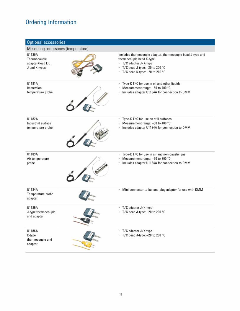
Ordering Information
Optional accessoriesMeasuring accessories (temperature)U1180A Thermocouple adapter+lead kit, J and K types
Includes thermocouple adapter, thermocouple bead J-type and thermocouple bead K-type.• T/C adapter J/K-type• T/C bead J-type: –20 to 200 °C• T/C bead K-type: –20 to 200 °C
U1181A Immersion temperature probe
• Type-K T/C for use in oil and other liquids• Measurement range: –50 to 700 ºC• Includes adapter U1184A for connection to DMM
U1182A Industrial surface temperature probe
• Type-K T/C for use on still surfaces• Measurement range: –50 to 400 ºC• Includes adapter U1184A for connection to DMM
U1183A Air temperature probe
• Type-K T/C for use in air and non-caustic gas• Measurement range: –50 to 800 ºC• Includes adapter U1184A for connection to DMM
U1184A Temperature probe adapter
• Mini-connector-to-banana-plug adapter for use with DMM
U1185A J-type thermocouple and adapter
• T/C adapter J/K-type• T/C bead J-type: –20 to 200 °C
U1186A K-type thermocouple and adapter
• T/C adapter J/K-type• T/C bead J-type: –20 to 200 °C
20
Ordering Information
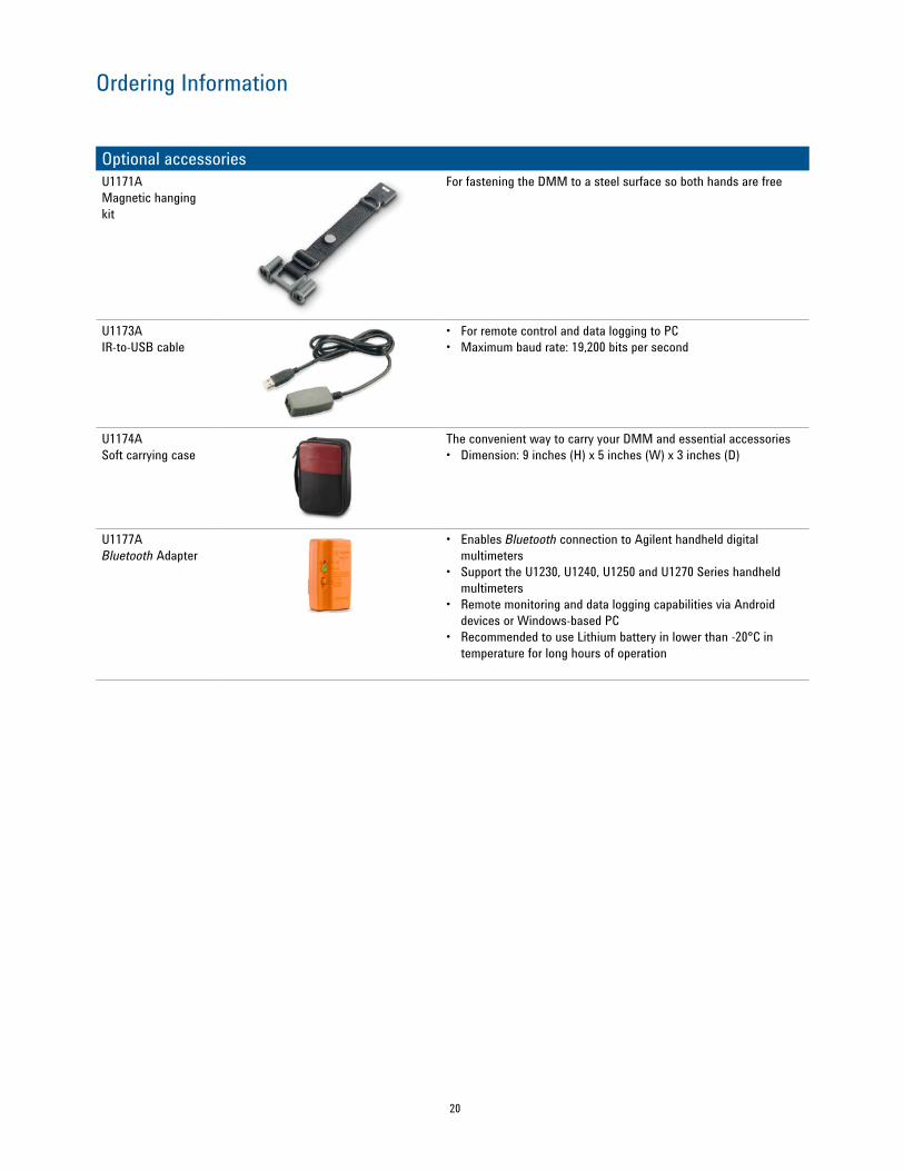
Optional accessoriesU1171A Magnetic hanging kit
For fastening the DMM to a steel surface so both hands are free
U1173A IR-to-USB cable
• For remote control and data logging to PC• Maximum baud rate: 19,200 bits per second
U1174A Soft carrying case
The convenient way to carry your DMM and essential accessories• Dimension: 9 inches (H) x 5 inches (W) x 3 inches (D)
U1177A Bluetooth Adapter
• Enables Bluetooth connection to Agilent handheld digital multimeters
• Support the U1230, U1240, U1250 and U1270 Series handheld multimeters
• Remote monitoring and data logging capabilities via Android devices or Windows-based PC
• Recommended to use Lithium battery in lower than -20°C in temperature for long hours of operation
www.agilent.comwww.agilent.com/find/handhelddmm
www.lxistandard.org LAN eXtensions for Instruments puts the power of Ethernet and the Web inside your test systems. Agilent is a founding member of the LXI consortium.
Agilent Channel Partnerswww.agilent.com/find/channelpartnersGet the best of both worlds: Agilent’s measurement expertise and product breadth, combined with channel partner convenience.
For more information on Agilent Technologies’ products, applications or services, please contact your local Agilent office. The complete list is available at:www.agilent.com/find/contactus
Americas Canada (877) 894 4414 Brazil (11) 4197 3600Mexico 01800 5064 800 United States (800) 829 4444
Asia Pacific Australia 1 800 629 485China 800 810 0189Hong Kong 800 938 693India 1 800 112 929Japan 0120 (421) 345Korea 080 769 0800Malaysia 1 800 888 848Singapore 1 800 375 8100Taiwan 0800 047 866Other AP Countries (65) 375 8100
Europe & Middle EastBelgium 32 (0) 2 404 93 40 Denmark 45 45 80 12 15Finland 358 (0) 10 855 2100France 0825 010 700* *0.125 €/minuteGermany 49 (0) 7031 464 6333 Ireland 1890 924 204Israel 972-3-9288-504/544Italy 39 02 92 60 8484Netherlands 31 (0) 20 547 2111Spain 34 (91) 631 3300Sweden 0200-88 22 55United Kingdom 44 (0) 118 927 6201Forotherunlistedcountries: www.agilent.com/find/contactus(BP-3-1-13)
Product specifications and descriptions in this document subject to change without notice.
© Agilent Technologies, Inc. 2013Published in USA, October 1, 20135990-6425EN
www.agilent.com/quality
www.axiestandard.org AdvancedTCA® Extensions for Instrumentation and Test (AXIe) is an open standard that extends the AdvancedTCA for general purpose and semiconductor test. Agilent is a founding member of the AXIe consortium.
www.pxisa.org PCI eXtensions for Instrumentation (PXI) modular instrumentation delivers a rugged, PC-based high-performance measurement and automation system.
Quality Management SystemQuality Management SysISO 9001:2008Agilent Electronic Measurement Group
DEKRA Certified
www.agilent.com/find/myagilent A personalized view into the information most relevant to you.
myAgilentmyAgilent
www.agilent.com/find/AdvantageServicesAccurate measurements throughout the life of your instruments.
Agilent Advantage Services
Three-Year Warranty
www.agilent.com/find/ThreeYearWarrantyAgilent’s combination of product reliability and three-year warranty coverage is another way we help you achieve your business goals: increased confidence in uptime, reduced cost of ownership and greater convenience.