Embed Size (px)
Citation preview
Agilent 75000 SERIES B
Agilent E1351A/E1353A16-Channel FET MultiplexerModules
User’s Manual
Copyright© Agilent Technologies, Inc., 1995 - 2006
*E1351-90004*E1351-90004
E0506
Manual Part Number: E1351-90004Microfiche Part Number: E1351-99004
Printed: May 2006 Edition 4 Rev 2Printed in Malaysia E0506

ContentsAgilent E1351A/53A 16-Channel FET Multiplexer
Warranty . . . . . . . . . . . . . . . . . . . . . . . . . . . . . . . . . . . . . . . . . . 5WARNINGS . . . . . . . . . . . . . . . . . . . . . . . . . . . . . . . . . . . . . . . . 6Safety Symbols . . . . . . . . . . . . . . . . . . . . . . . . . . . . . . . . . . . . . . 6Declaration of Conformity . . . . . . . . . . . . . . . . . . . . . . . . . . . . . . . . . 7-8User’s Notes . . . . . . . . . . . . . . . . . . . . . . . . . . . . . . . . . . . . . . . . 9
Chapter 1. Getting Started with the Agilent E1351A/53A . . . . . . . . . . . . . . . . . . . . 11
Using This Chapter . . . . . . . . . . . . . . . . . . . . . . . . . . . . . . . . . . . . 11FET Multiplexer Module Description . . . . . . . . . . . . . . . . . . . . . . . . . . . 11Multimeter Connection Points . . . . . . . . . . . . . . . . . . . . . . . . . . . . . . . 12
Analog Bus Connector . . . . . . . . . . . . . . . . . . . . . . . . . . . . . . . . 12Tree Terminals . . . . . . . . . . . . . . . . . . . . . . . . . . . . . . . . . . . . 12
Direct Terminals . . . . . . . . . . . . . . . . . . . . . . . . . . . . . . . . . . . 12Switchbox and Scanning Voltmeter Configurations . . . . . . . . . . . . . . . . . . . 14
Switchbox . . . . . . . . . . . . . . . . . . . . . . . . . . . . . . . . . . . . . . . 14
Scanning Voltmeter . . . . . . . . . . . . . . . . . . . . . . . . . . . . . . . . . . 15Digital Bus and Triggering . . . . . . . . . . . . . . . . . . . . . . . . . . . . . . . . 15Programming Language . . . . . . . . . . . . . . . . . . . . . . . . . . . . . . . . . . 16Initial Operation . . . . . . . . . . . . . . . . . . . . . . . . . . . . . . . . . . . . . . 16
Chapter 2. Configuring the Agilent E1351A/53A FET Multiplexer Modules . . . . . . . . . . 17
Using This Chapter . . . . . . . . . . . . . . . . . . . . . . . . . . . . . . . . . . . . 17Warnings and Cautions . . . . . . . . . . . . . . . . . . . . . . . . . . . . . . . . . . 17Multiplexer Card Numbers . . . . . . . . . . . . . . . . . . . . . . . . . . . . . . . . 18
Setting the Address Switch . . . . . . . . . . . . . . . . . . . . . . . . . . . . . . 19Selecting the Interrupt Line Number . . . . . . . . . . . . . . . . . . . . . . . . . . . 20Setting the Card ID Switch . . . . . . . . . . . . . . . . . . . . . . . . . . . . . . . . 21Connecting User Inputs . . . . . . . . . . . . . . . . . . . . . . . . . . . . . . . . . . 22Adding Signal Conditioning Components/Current Shunts . . . . . . . . . . . . . . . . 23Connecting Field Wiring . . . . . . . . . . . . . . . . . . . . . . . . . . . . . . . . . 24
Wiring Guidelines . . . . . . . . . . . . . . . . . . . . . . . . . . . . . . . . . . 24Wiring a Terminal Module . . . . . . . . . . . . . . . . . . . . . . . . . . . . . . . . 25Connecting Multimeters and Signal Generators . . . . . . . . . . . . . . . . . . . . . 26Analog Bus and Digital Bus Cables . . . . . . . . . . . . . . . . . . . . . . . . . . . . 27
Chapter 3. Using the Agilent E1351A/53A FET Multiplexer Modules . . . . . . . . . . . . . . 29
Using This Chapter . . . . . . . . . . . . . . . . . . . . . . . . . . . . . . . . . . . . 29Selecting Channels . . . . . . . . . . . . . . . . . . . . . . . . . . . . . . . . . . . . . 29Multiplexer Commands . . . . . . . . . . . . . . . . . . . . . . . . . . . . . . . . . . 31Connecting Switchbox Channels to Direct Terminals . . . . . . . . . . . . . . . . . . 32Connecting Switchbox Channels to Tree Terminals for Making Measurements . . . . . 34Scanning a Range of Switchbox Channels . . . . . . . . . . . . . . . . . . . . . . . . 36Downloading a Scan List . . . . . . . . . . . . . . . . . . . . . . . . . . . . . . . . . 39Scanning a Switchbox without a Downloaded Scan List . . . . . . . . . . . . . . . . . 40Scanning a Switchbox with a Downloaded Scan List . . . . . . . . . . . . . . . . . . . 41Scanning Voltmeter Configuration with Agilent E1326B . . . . . . . . . . . . . . . . 42Measuring Temperature Using Thermocouples (Agilent E1353A Module only) . . . . 43
Setup for Measuring Thermocouple Temperature using an External Multimeter . . 43
Agilent E1351A/53A 16-Channel FET Multiplexer Contents 1
Chapter 4. Understanding the Agilent E1351A/53A FET Multiplexer Modules . . . . . . . . . 45
Using This Chapter . . . . . . . . . . . . . . . . . . . . . . . . . . . . . . . . . . . . 45Commands for Scanning Switchbox Channels . . . . . . . . . . . . . . . . . . . . . . 45Using Scanning Trigger Sources . . . . . . . . . . . . . . . . . . . . . . . . . . . . . 45
Scanning with External Instruments . . . . . . . . . . . . . . . . . . . . . . . . . 45Using the Scan Complete Bit . . . . . . . . . . . . . . . . . . . . . . . . . . . . . . . 52
Chapter 5. Agilent E1351A/53A 16-Channel FET Multiplexer Command Reference . . . . . . 53
Using This Chapter . . . . . . . . . . . . . . . . . . . . . . . . . . . . . . . . . . . . 53Command Types . . . . . . . . . . . . . . . . . . . . . . . . . . . . . . . . . . . . . . 53
Common Command Format . . . . . . . . . . . . . . . . . . . . . . . . . . . . . 53SCPI Command Format . . . . . . . . . . . . . . . . . . . . . . . . . . . . . . . 53
Linking Commands . . . . . . . . . . . . . . . . . . . . . . . . . . . . . . . . . . 55SCPI Command Reference . . . . . . . . . . . . . . . . . . . . . . . . . . . . . . . . 55ABORt . . . . . . . . . . . . . . . . . . . . . . . . . . . . . . . . . . . . . . . . . . . 56ARM . . . . . . . . . . . . . . . . . . . . . . . . . . . . . . . . . . . . . . . . . . . . 57
:COUNt . . . . . . . . . . . . . . . . . . . . . . . . . . . . . . . . . . . . . . . . 57
:COUNt? . . . . . . . . . . . . . . . . . . . . . . . . . . . . . . . . . . . . . . . 57DISPlay . . . . . . . . . . . . . . . . . . . . . . . . . . . . . . . . . . . . . . . . . . 58
:MONitor:CARD . . . . . . . . . . . . . . . . . . . . . . . . . . . . . . . . . . . 58
:MONitor[:STATe] . . . . . . . . . . . . . . . . . . . . . . . . . . . . . . . . . . 59INITiate . . . . . . . . . . . . . . . . . . . . . . . . . . . . . . . . . . . . . . . . . . 60
:CONTinuous . . . . . . . . . . . . . . . . . . . . . . . . . . . . . . . . . . . . . 60
:CONTinuous? . . . . . . . . . . . . . . . . . . . . . . . . . . . . . . . . . . . . 61[:IMMediate] . . . . . . . . . . . . . . . . . . . . . . . . . . . . . . . . . . . . . 61
OUTPut . . . . . . . . . . . . . . . . . . . . . . . . . . . . . . . . . . . . . . . . . . 62
[:STATe] . . . . . . . . . . . . . . . . . . . . . . . . . . . . . . . . . . . . . . . 62[:STATe]? . . . . . . . . . . . . . . . . . . . . . . . . . . . . . . . . . . . . . . . 62
[ROUTe:] . . . . . . . . . . . . . . . . . . . . . . . . . . . . . . . . . . . . . . . . . 63
CLOSe . . . . . . . . . . . . . . . . . . . . . . . . . . . . . . . . . . . . . . . . 63CLOSe? . . . . . . . . . . . . . . . . . . . . . . . . . . . . . . . . . . . . . . . . 64
OPEN . . . . . . . . . . . . . . . . . . . . . . . . . . . . . . . . . . . . . . . . . 64OPEN? . . . . . . . . . . . . . . . . . . . . . . . . . . . . . . . . . . . . . . . . 65
SCAN . . . . . . . . . . . . . . . . . . . . . . . . . . . . . . . . . . . . . . . . . 65SCAN:MODE . . . . . . . . . . . . . . . . . . . . . . . . . . . . . . . . . . . . . 67
SCAN:MODE? . . . . . . . . . . . . . . . . . . . . . . . . . . . . . . . . . . . . 67SCAN:PORT . . . . . . . . . . . . . . . . . . . . . . . . . . . . . . . . . . . . . 68
SCAN:PORT? . . . . . . . . . . . . . . . . . . . . . . . . . . . . . . . . . . . . 68SETTling[:TIME] . . . . . . . . . . . . . . . . . . . . . . . . . . . . . . . . . . . 69
SETTling[:TIME]? . . . . . . . . . . . . . . . . . . . . . . . . . . . . . . . . . . 69STATus . . . . . . . . . . . . . . . . . . . . . . . . . . . . . . . . . . . . . . . . . . 70
:OPERation:ENABle . . . . . . . . . . . . . . . . . . . . . . . . . . . . . . . . . 70
:OPERation[:EVENt]? . . . . . . . . . . . . . . . . . . . . . . . . . . . . . . . . 70SYSTem . . . . . . . . . . . . . . . . . . . . . . . . . . . . . . . . . . . . . . . . . . 71
:CDEScription? . . . . . . . . . . . . . . . . . . . . . . . . . . . . . . . . . . . . 71
:CPON . . . . . . . . . . . . . . . . . . . . . . . . . . . . . . . . . . . . . . . . 71:CTYPe? . . . . . . . . . . . . . . . . . . . . . . . . . . . . . . . . . . . . . . . 72
:ERRor? . . . . . . . . . . . . . . . . . . . . . . . . . . . . . . . . . . . . . . . . 72TRIGger . . . . . . . . . . . . . . . . . . . . . . . . . . . . . . . . . . . . . . . . . . 73
[:IMMediate] . . . . . . . . . . . . . . . . . . . . . . . . . . . . . . . . . . . . . 73
2 Agilent E1351A/53A 16-Channel FET Multiplexer Contents
:SOURce . . . . . . . . . . . . . . . . . . . . . . . . . . . . . . . . . . . . . . . 74
:SOURce? . . . . . . . . . . . . . . . . . . . . . . . . . . . . . . . . . . . . . . . 75IEEE 488.2 Common Commands . . . . . . . . . . . . . . . . . . . . . . . . . . . . . 76Command Quick Reference . . . . . . . . . . . . . . . . . . . . . . . . . . . . . . . . 77
Appendix A. Agilent E1351A/53A FET Multiplexer Specifications . . . . . . . . . . . . . . . 79
Appendix B. Agilent E1351A/53A Register-Based Programming . . . . . . . . . . . . . . . . 81
About This Appendix . . . . . . . . . . . . . . . . . . . . . . . . . . . . . . . . . . . 81Register Addressing . . . . . . . . . . . . . . . . . . . . . . . . . . . . . . . . . . . . 81
The Base Address . . . . . . . . . . . . . . . . . . . . . . . . . . . . . . . . . . . 83A16 Address Space Outside the Command Module or Mainframe . . . . . . . . . 83
A16 Address Space Inside the Command Module or Mainframe . . . . . . . . . . 83Register Offset . . . . . . . . . . . . . . . . . . . . . . . . . . . . . . . . . . . . 84
Register Descriptions . . . . . . . . . . . . . . . . . . . . . . . . . . . . . . . . . . . 84WRITE Registers . . . . . . . . . . . . . . . . . . . . . . . . . . . . . . . . . . . 84READ Registers . . . . . . . . . . . . . . . . . . . . . . . . . . . . . . . . . . . 84
Register Bit Descriptions . . . . . . . . . . . . . . . . . . . . . . . . . . . . . . . . . 86Manufacturer ID Register . . . . . . . . . . . . . . . . . . . . . . . . . . . . . . 86Device Type Register . . . . . . . . . . . . . . . . . . . . . . . . . . . . . . . . . 86
Status/Control Register . . . . . . . . . . . . . . . . . . . . . . . . . . . . . . . . 87Scan Control Register . . . . . . . . . . . . . . . . . . . . . . . . . . . . . . . . . 88
Scan Channel Delay Register . . . . . . . . . . . . . . . . . . . . . . . . . . . . . 88Scan Channel Configuration Register . . . . . . . . . . . . . . . . . . . . . . . . 89
Direct Channel Configuration Register . . . . . . . . . . . . . . . . . . . . . . . . 89Direct Control Register . . . . . . . . . . . . . . . . . . . . . . . . . . . . . . . . 90
Executing Commands . . . . . . . . . . . . . . . . . . . . . . . . . . . . . . . . . . . 90Register-Based Programming for Maximum Speed . . . . . . . . . . . . . . . . . . . 93
Multimeter Command and Parameter Opcodes . . . . . . . . . . . . . . . . . . . 96Multimeter Register-Based Programming Error Codes . . . . . . . . . . . . . . . 98
Appendix C. Agilent E1351A/53A FET Multiplexer Error Messages . . . . . . . . . . . . . . 99
Index . . . . . . . . . . . . . . . . . . . . . . . . . . . . . . . . . . . . . . . . . . . . . . . . 101
Agilent E1351A/53A 16-Channel FET Multiplexer Contents 3

Notes
4 Agilent E1351A/53A 16-Channel FET Multiplexer Contents
CertificationAgilent Technologies certifies that this product met its published specifications at the time of shipment from the factory. AgilentTechnologies further certifies that its calibration measurements are traceable to the United States National Institute of Standards andTechnology (formerly National Bureau of Standards), to the extent allowed by that organization’s calibration facility, and to the calibrationfacilities of other International Standards Organization members.
WarrantyThis Agilent Technologies product is warranted against defects in materials and workmanship for a period of one (1) year from date ofshipment. Duration and conditions of warranty for this product may be superseded when the product is integrated into (becomes a partof) other Agilent products. During the warranty period, Agilent Technologies will, at its option, either repair or replace products whichprove to be defective.
For warranty service or repair, this product must be returned to a service facility designated by Agilent Technologies. Buyer shall prepayshipping charges to Agilent and Agilent shall pay shipping charges to return the product to Buyer. However, Buyer shall pay all shippingcharges, duties, and taxes for products returned to Agilent from another country.
Agilent warrants that its software and firmware designated by Agilent for use with a product will execute its programming instructionswhen properly installed on that product. Agilent does not warrant that the operation of the product, or software, or firmware will beuninterrupted or error free.
Limitation Of WarrantyThe foregoing warranty shall not apply to defects resulting from improper or inadequate maintenance by Buyer, Buyer-supplied productsor interfacing, unauthorized modification or misuse, operation outside of the environmental specifications for the product, or improper sitepreparation or maintenance.
The design and implementation of any circuit on this product is the sole responsibility of the Buyer. Agilent does not warrant the Buyer’scircuitry or malfunctions of Agilent products that result from the Buyer’s circuitry. In addition, Agilent does not warrant any damage thatoccurs as a result of the Buyer’s circuit or any defects that result from Buyer-supplied products.
NO OTHER WARRANTY IS EXPRESSED OR IMPLIED. Agilent SPECIFICALLY DISCLAIMS THE IMPLIED WARRANTIESOF MERCHANTABILITY AND FITNESS FOR A PARTICULAR PURPOSE.
Exclusive RemediesTHE REMEDIES PROVIDED HEREIN ARE BUYER’S SOLE AND EXCLUSIVE REMEDIES. Agilent SHALL NOT BE LIABLEFOR ANY DIRECT, INDIRECT, SPECIAL, INCIDENTAL, OR CONSEQUENTIAL DAMAGES, WHETHER BASED ON CON-TRACT, TORT, OR ANY OTHER LEGAL THEORY.
NoticeThe information contained in this document is subject to change without notice. Agilent Technologies MAKES NO WARRANTY OFANY KIND WITH REGARD TO THIS MATERIAL, INCLUDING, BUT NOT LIMITED TO, THE IMPLIED WARRANTIES OFMERCHANTABILITY AND FITNESS FOR A PARTICULAR PURPOSE. Agilent shall not be liable for errors contained herein or forincidental or consequential damages in connection with the furnishing, performance or use of this material. This document containsproprietary information which is protected by copyright. All rights are reserved. No part of this document may be photocopied, reproduced,or translated to another language without the prior written consent of Agilent Technologies, Inc. Agilent assumes no responsibility for theuse or reliability of its software on equipment that is not furnished by Agilent.
U.S. Government Restricted RightsThe Software and Documentation have been developed entirely at private expense. They are delivered and licensed as "commercialcomputer software" as defined in DFARS 252.227- 7013 (Oct 1988), DFARS 252.211-7015 (May 1991) or DFARS 252.227-7014 (Jun1995), as a "commercial item" as defined in FAR 2.101(a), or as "Restricted computer software" as defined in FAR 52.227-19 (Jun 1987)(orany equivalent agency regulation or contract clause), whichever is applicable. You have only those rights provided for such Software andDocumentation by the applicable FAR or DFARS clause or the Agilent standard software agreement for the product involved.
Agilent E1351A / E1353A 16-Channel FET Multiplexer Module User’s ManualEdition 4 Rev 2
Copyright © 1995-2006 Agilent Technologies, Inc. All Rights Reserved.
Agilent E1351A / E1353A 16-Channel FET Multiplexer Module User’s Manual 5
Frame or chassis ground terminal—typicallyconnects to the equipment’s metal frame.
Alternating current (AC).
Direct current (DC).
Indicates hazardous voltages.
Calls attention to a procedure, practice, or con-dition that could cause bodily injury or death.
Calls attention to a procedure, practice, or con-dition that could possibly cause damage toequipment or permanent loss of data.
Indicates the field wiring terminal that mustbe connected to earth ground before operatingthe equipment—protects against electricalshock in case of fault.
Instruction manual symbol affixed to product.Indicates that the user must refer to the man-ual for specific WARNING or CAUTIONinformation to avoid personal injury or dam-age to the product.
or
WARNINGSThe following general safety precautions must be observed during all phases of operation, service, and repair of this product.Failure to comply with these precautions or with specific warnings elsewhere in this manual violates safety standards of design,manufacture, and intended use of the product. Agilent Technologies assumes no liability for the customer’s failure to comply withthese requirements.
Ground the equipment: For Safety Class 1 equipment (equipment having a protective earth terminal), an uninterruptible safety earthground must be provided from the mains power source to the product input wiring terminals or supplied power cable.
DO NOT operate the product in an explosive atmosphere or in the presence of flammable gases or fumes.
For continued protection against fire, replace the line fuse(s) only with fuse(s) of the same voltage and current rating and type. DO NOT use repaired fuses or short-circuited fuse holders.
Keep away from live circuits: Operating personnel must not remove equipment covers or shields. Procedures involving the removal ofcovers or shields are for use by service-trained personnel only. Under certain conditions, dangerous voltages may exist even with theequipment switched off. To avoid dangerous electrical shock, DO NOT perform procedures involving cover or shield removal unless youare qualified to do so.
DO NOT operate damaged equipment: Whenever it is possible that the safety protection features built into this product have beenimpaired, either through physical damage, excessive moisture, or any other reason, REMOVE POWER and do not use the product untilsafe operation can be verified by service-trained personnel. If necessary, return the product to an Agilent Technologies Sales and ServiceOffice for service and repair to ensure that safety features are maintained.
DO NOT service or adjust alone: Do not attempt internal service or adjustment unless another person, capable of rendering first aid andresuscitation, is present.
DO NOT substitute parts or modify equipment: Because of the danger of introducing additional hazards, do not install substitute partsor perform any unauthorized modification to the product. Return the product to an Agilent Technologies Sales and Service Office forservice and repair to ensure that safety features are maintained.
Printing HistoryThe Printing History shown below lists all Editions and Updates of this manual and the printing date(s). The first printing of the manualis Edition 1. The Edition number increments by 1 whenever the manual is revised. Updates, which are issued between Editions, containreplacement pages to correct the current Edition of the manual. Updates are numbered sequentially starting with Update 1. When a newEdition is created, it contains all the Update information for the previous Edition. Each new Edition or Update also includes a revised copyof this printing history page. Many product updates or revisions do not require manual changes and, conversely, manual corrections maybe done without accompanying product changes. Therefore, do not expect a one-to-one correspondence between product updates andmanual updates.
Edition 1 . . . . . . . . . . . . . . . . . . . . . . . . . . . . . . . . . . . . . . . . . . . . . . August 1990
Edition 2 . . . . . . . . . . . . . . . . . . . . . . . . . . . . . . . . . . . . . . . . . . . September 1993
Edition 3 . . . . . . . . . . . . . . . . . . . . . . . . . . . . . . . . . . . . . . . . . . . . . . August 1994
Edition 4 (Part Number E1351-90004). . . . . . . . . . . . . . . . . . . . . . . . . July 1995
Edition 4 Rev 2 (Part Number E1351-90004) . . . . . . . . . . . . . . . . . . . May 2006
Safety Symbols
WARNING
CAUTION
6 Agilent E1351A / E1353A 16-Channel FET Multiplexer Module User’s Manual

DECLARATION OF CONFORMITYAccording to ISO/IEC Guide 22 and CEN/CENELEC EN 45014
Agilent E1351A / E1353A 16-Channel FET Multiplexer Module User’s Manual 7
Manufacturer’s Name: Agilent Technologies, IncorporatedManufacturer’s Address: 815 – 14th St. SW
Loveland, Colorado 80537USA
Declares, that the product
Product Name: 16 Channel FET MultiplexerModel Number: E1351AProduct Options: This declaration covers all options of the above product(s).
Conforms with the following European Directives:
The product herewith complies with the requirements of the Low Voltage Directive 73/23/EEC and the EMC Directive 89/336/EEC(including 93/68/EEC) and carries the CE Marking accordingly.
Conforms with the following product standards:
EMC Standard
CISPR 11:1990 / EN 55011:1991EN50082-1 :1992IEC 1000-4-2 :1995IEC 1000-4-3 :1995IEC 1000-4-4 :1995
Limit
Group 1 Class A
4kV CD, 8kV AD3 V/m0.5kV signal lines, 1kV power lines
The produt was tested in a typical configuration with Agilent Technologies or Hewlett-Packard Company testsystems
Safety IEC 1010-1:1990+A2:1996 / EN 61010-1:1993Canada: CSA C22.2 No. 1010.1:1992UL 3111-1 : 1994
3 May 2001Date Ray Corson
Product Regulations Program Manager
For further information, please contact your local Agilent Technologies sales office, agent or distributor.Authorized EU-representative: Agilent Technologies Deutschland GmbH, Herrenberger Straβe 130, D 71034 Böblingen, Germany

DECLARATION OF CONFORMITYAccording to ISO/IEC Guide 22 and CEN/CENELEC EN 45014
8 Agilent E1351A / E1353A 16-Channel FET Multiplexer Module User’s Manual
Manufacturer’s Name: Agilent Technologies, IncorporatedManufacturer’s Address: 815 – 14th St. SW
Loveland, Colorado 80537USA
Declares, that the product
Product Name: 16 Channel T/C FET MultiplexerModel Number: E1353AProduct Options: This declaration covers all options of the above product(s).
Conforms with the following European Directives:
The product herewith complies with the requirements of the Low Voltage Directive 73/23/EEC and the EMC Directive 89/336/EEC(including 93/68/EEC) and carries the CE Marking accordingly.
Conforms with the following product standards:
EMC Standard
CISPR 11:1990 / EN 55011:1991EN50082-1 :1992IEC 1000-4-2 :1995IEC 1000-4-3 :1995IEC 1000-4-4 :1995
Limit
Group 1 Class A
4kV CD, 8kV AD3 V/m0.5kV signal lines, 1kV power lines
The produt was tested in a typical configuration with Agilent Technologies or Hewlett-Packard Company testsystems
Safety IEC 1010-1:1990+A2:1996 / EN 61010-1:1993Canada: CSA C22.2 No. 1010.1:1992UL 3111-1 : 1994
3 May 2001Date Ray Corson
Product Regulations Program Manager
For further information, please contact your local Agilent Technologies sales office, agent or distributor.Authorized EU-representative: Agilent Technologies Deutschland GmbH, Herrenberger Straβe 130, D 71034 Böblingen, Germany

Notes
Agilent E1351A / E1353A 16-Channel FET Multiplexer Module User’s Manual 9

Notes
10 Agilent E1351A / E1353A 16-Channel FET Multiplexer Module User’s Manual
Chapter 1Getting Started with the Agilent E1351A/53A
Using This Chapter
This chapter describes the Agilent E1351A 16-Channel FET and the AgilentE1353A 16-Channel Thermocouple FET Multiplexer Modules, and showshow to program the modules using SCPI (Standard Commands forProgrammable Instruments) commands. This chapter contains thefollowing sections:
• FET Multiplexer Module Description . . . . . . . . . . . . . . . . . . Page 11• Multimeter Connection Points . . . . . . . . . . . . . . . . . . . . . . . . Page 12• Switchbox & Scanning Voltmeter Configurations . . . . . . . . Page 14• Digital Bus and Triggering . . . . . . . . . . . . . . . . . . . . . . . . . . Page 15• Programming Language. . . . . . . . . . . . . . . . . . . . . . . . . . . . . Page 16• Initial Operation . . . . . . . . . . . . . . . . . . . . . . . . . . . . . . . . . . . Page 16
FET Multiplexer Module Description
The FET multiplexer module provides high-speed switching (multiplexing)for up to 16 channels. The module can be used as a scanning multiplexerfor a scanning voltmeter configuration, or as a stand-alone multiplexer in aswitchbox configuration. The channels are numbered 00 to 15. Eachchannel provides connections for High (H), Low (L) and Guard (G),although only High and Low are switched. The FET multiplexer modulecan switch up to 100,000 connections per second (100 K switches/sec).
The FET multiplexer module consists of a component assembly and aterminal module. There are three different terminal modules, one for eachof the following applications: Agilent E1351A 16-Channel FET MultiplexerModule, Agilent E1353A 16-Channel Thermocouple FET MultiplexerModule, and Agilent E1352A 32-Channel Single-Ended FET MultiplexerModule. The component assembly is the same for all three applications. Forinformation on the 32-Channel Single-Ended FET Multiplexer Module, seethe Agilent E1352A User’s Manual.
The component assembly contains the VXIbus interface, the FET switches,the analog bus connector and the digital bus. The terminal modules provideconnection points for the individual channels, as well as monitoring pointsfor the tree terminals and the direct terminals. The FET multiplexer modulecan be externally triggered from the VXIbus backplane or through thedigital bus handshake lines on the front of the component assembly.
Chapter 1 Getting Started with the Agilent E1351A/53A 11
For high-speed operation (100 K switches/sec.) the scanning list isautomatically downloaded into RAM on the multiplexer module.Triggering for channel advance is from the two handshake lines on thedigital bus. The scanning operation does not require any intervention fromthe mainframe CPU. This only applies for switchboxes or scanningvoltmeter configurations that have all FET multiplexer modules. For adownloaded scan list in switchboxes, the trigger source must beTRIG:SOUR DBUS or TRIG:SOUR IMM.
Multimeter Connection Points
There are three places where signals on a closed channel can be measured:analog bus connector, tree terminals and direct terminals. Each of theseprovides a different capability for configuring the module.
Analog BusConnector
The analog bus connector provides a direct connection between multiplemultiplexer modules and also between a multiplexer module and AgilentE1326/E1411 Multimeters. A ribbon cable is used to daisy-chain multiplemultiplexer modules together, and to connect a multimeter to themultiplexer modules for a scanning voltmeter. The SCAN:PORT ABUScommand automatically closes the appropriate tree isolation switches toroute closed channels to the analog bus. This command must be executed ina switchbox configuration. A scanning voltmeter automatically configuresthe multiplexer for the analog bus connector.
Tree Terminals Tree terminals provide an external connection point through the terminalmodules for the signals which are on the analog bus lines. Tree terminalsare the recommended connection points for connecting stand-alonemultimeters and external current sources for 4-wire resistancemeasurements.
Direct Terminals The 16 channels are separated into two banks, Bank 0 and Bank 1. When achannel is closed, that channel is connected to a Bank Common. Channels00 to 07 are on Bank 0 Common and channels 08 to 15 are on Bank 1Common. The terminal module has connection points for the directterminals, where you can measure signals on the respective Bank Commons.The banks can be isolated from each other, from the analog bus connector,and from the tree terminals with the A and B tree isolation switches.
12 Getting Started with the Agilent E1351A/53A Chapter 1
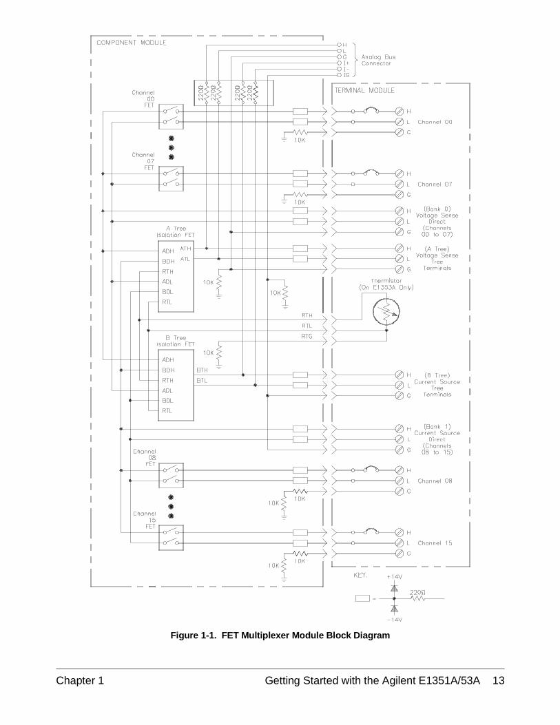
Figure 1-1. FET Multiplexer Module Block Diagram
Chapter 1 Getting Started with the Agilent E1351A/53A 13
Switchbox and Scanning Voltmeter Configurations
A VXIbus instrument is a module or group of modules which perform aspecified function. For the Agilent E1300/01 mainframe, the first module inan instrument must have a logical address which is evenly divisible by 8(16, 24, 112), and the rest of the modules in the instrument are numberedconsecutively. The instrument’s secondary address is the whole numberequal to the logical address divided by 8 (for a logical address of 16, 17,18,…23, the secondary address is 02). For instrument definition in othermainframes, see the mainframe manual. If an instrument consists of onlymultiplexer modules, it is a switchbox configuration. If a multiplexermodule(s) is combined with a multimeter to form an instrument, that is ascanning voltmeter configuration.
Switchbox A switchbox is a multiplexer module or group of multiplexer moduleswhich form a single instrument. A switchbox can be connected to amultimeter which is a different VXIbus instrument, to an GPIB1 controlledmultimeter, or to a stand-alone multimeter. The switchbox and themultimeter have different secondary addresses. Separate configurationcommands must be sent to the switchbox and to the multimeter. Thefollowing program illustrates the different addresses and the configurationcommands required. The GPIB interface select code is 7, and themainframe address is 09. The multiplexer has an instrument address of 24,so its secondary address is 03. The multimeter is GPIB controlled, and hasa primary address of 22.
10 OUTPUT 722;"TRIG EXT;DC 10" !Sets multimeter to external triggerand to measure DC volts
20 OUTPUT 70903;"OUTP ON" !Enables "Trig Out" port
30 OUTPUT 70903;"TRIG:SOUR BUS" !Sets switchbox to receive Bustriggers
40 OUTPUT 70903;"SCAN:MODE VOLT"!Set up switchbox for voltagemeasurements
50 OUTPUT 70903;"SCAN:PORT ABUS"!Closes the appropriate treeisolation switches while scanning,automatically makes connection tothe analog bus and tree terminals.
60 OUTPUT 70903;"ARM:COUN 2" !Set for two cycles through thescan list
70 OUTPUT 70903;"SCAN (@100;115)"!Selects the channel list. 100selects first channel on card 1; 115 selects last channel on card 1
80 OUTPUT 70903;"INIT" !Close first channel to startscanning cycle
90 FOR I = 0 TO 15 !Start count loop
100 ENTER 722;A !Enter reading into variable A
110 PRINT A !Print reading in variable A
14 Getting Started with the Agilent E1351A/53A Chapter 1
1 GPIB is the implementation of IEEE Std 488.1-1978
120 TRIGGER 70903 !Trigger the switchbox to advancethe channel list
130 NEXT I !Increment count
140 END
Scanning Voltmeter When the multiplexer(s) is combined with a multimeter to form a singleinstrument, they become a virtual instrument, a scanning voltmeter. Themultiplexer(s) and the multimeter have the same secondary address. Themultimeter automatically configures the multiplexer, so the SCAN:MODE,SCAN:PORT and TRIG:SOUR commands are not required. Channeladvance is from the digital bus handshake lines, so the count loop is notrequired. The ARM:COUN command does not apply to downloaded scanlists, so you cannot specify the number of cycles through the scan list. Youcan, however, specify INIT:CONT ON for continuous scanning through thescan list.
10 DIM Rdgs(1:16) !Dimension an array for 16readings
20 OUTPUT 70903;"*RST" !Reset instrument
30 OUTPUT 70903;"MEAS:VOLT:DC? (@100:115)"!Configure instrument
40 ENTER 70903;Rdgs(*) !Enter readings into array
50 PRINT Rdgs(*) !Print results
60 END
Digital Bus and Triggering
The Agilent E1351A/E1353A can be triggered for channel advance from theVXIbus backplane or through the digital bus handshake cable on the front ofthe component assembly. Backplane triggering can come from GPIBcomputer commands over the GPIB Bus or from the Agilent E1300/1301Mainframe "Event In" port. Digital bus triggering uses two handshakelines; channel advance and channel closed. Channel advance (input tomultiplexer) triggers an advance, and channel closed (output frommultiplexer) signifies advance completed.
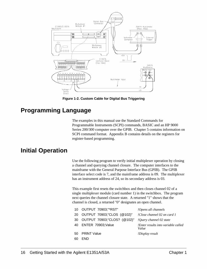
The Agilent E1326B Multimeter has a digital bus port on the face plate, andconnects to the multiplexer with the digital bus cable (see Figures 2-10 and2-11). To connect other multimeters for digital bus triggering, you mustprepare a custom cable. Use a connector like the one on the digital buscable (Agilent part number E1300-61611). Connect the measurementcomplete port from the multimeter to the channel advance pin, and theexternal trigger to the channel closed pin. Connect the grounds for bothsignals to the digital bus ground (second pin from right). You can use thiscable to connect an external multimeter to a switchbox, and then useTRlG:SOUR DBUS (digital bus triggering). You can also order a customcable with BNC to digital bus connectors, Agilent part numberE1411-80001. See Figure 2-11 for more information onmultiplexer-to-multiplexer and multiplexer-to-multimeter connections.
Chapter 1 Getting Started with the Agilent E1351A/53A 15
Programming Language
The examples in this manual use the Standard Commands forProgrammable Instruments (SCPI) commands, BASIC and an HP 9000Series 200/300 computer over the GPIB. Chapter 5 contains information onSCPI command format. Appendix B contains details on the registers forregister-based programming.
Initial Operation
Use the following program to verify initial multiplexer operation by closinga channel and querying channel closure. The computer interfaces to themainframe with the General Purpose Interface Bus (GPIB). The GPIBinterface select code is 7, and the mainframe address is 09. The multiplexerhas an instrument address of 24, so its secondary address is 03.
This example first resets the switchbox and then closes channel 02 of asingle multiplexer module (card number 1) in the switchbox. The programnext queries the channel closure state. A returned "1" shows that thechannel is closed, a returned "0" designates an open channel.
10 OUTPUT 70903;"*RST" !Opens all channels
20 OUTPUT 70903;"CLOS (@102)" !Close channel 02 on card 1
30 OUTPUT 70903;"CLOS? (@102)" !Query channel 02 state
40 ENTER 70903;Value !Enter results into variable calledValue
50 PRlNT Value !Display result
60 END
Figure 1-2. Custom Cable for Digital Bus Triggering
16 Getting Started with the Agilent E1351A/53A Chapter 1
Chapter 2Configuring the Agilent E1351A/53A FET
Multiplexer Modules
Using This Chapter
This chapter shows how to configure the 16-Channel FET MultiplexerModules, how to connect external wiring and how to connect multimeters.This chapter contains the following sections:
• Warnings and Cautions . . . . . . . . . . . . . . . . . . . . . . . . . . . . . Page 17• Multiplexer Card Numbers . . . . . . . . . . . . . . . . . . . . . . . . . . Page 18• Selecting the Interrupt Line Number . . . . . . . . . . . . . . . . . . . Page 20• Setting the Card ID Switch . . . . . . . . . . . . . . . . . . . . . . . . . . Page 21• Connecting User Inputs . . . . . . . . . . . . . . . . . . . . . . . . . . . . . Page 22• Adding Signal Conditioning Components/Current
Shunts . . . . . . . . . . . . . . . . . . . . . . . . . . . . . . . . . . . . . . . Page 23• Connecting Field Wiring . . . . . . . . . . . . . . . . . . . . . . . . . . . . Page 24• Wiring a Terminal Module . . . . . . . . . . . . . . . . . . . . . . . . . . Page 25• Connecting Multimeters and Signal Generators . . . . . . . . . . Page 26• Analog Bus and Digital Bus Cables . . . . . . . . . . . . . . . . . . . Page 27
Warnings and Cautions
Warning SHOCK HAZARD. Only service-trained personnel who areaware of the hazards involved should install, remove, orconfigure the multiplexer modules. Before you install anymodule, disconnect AC power from the mainframe and fromuser wiring.
Caution MAXIMUM VOLTAGE/CURRENT. The maximum voltage thatmay be applied between High (H), Low (L), and Guard (G)terminals is 15 V dc or 10.6 V rms (15 V peak). The maximumcurrent is 1 mA per channel.
STATIC ELECTRICITY. Static electricity is a major cause ofcomponent failure. To prevent damage to the electricalcomponents in the multiplexer module, observe anti-statictechniques whenever removing a module from the mainframe orwhenever working on a module.
Chapter 2 Configuring the Agilent E1351A/53A FET Multiplexer Modules 17
Multiplexer Card Numbers
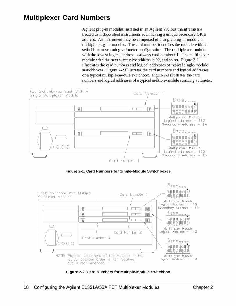
Agilent plug-in modules installed in an Agilent VXIbus mainframe aretreated as independent instruments each having a unique secondary GPIBaddress. An instrument may be composed of a single plug-in module ormultiple plug-in modules. The card number identifies the module within aswitchbox or scanning voltmeter configuration. The multiplexer modulewith the lowest logical address is always card number 01. The multiplexermodule with the next successive address is 02, and so on. Figure 2-1illustrates the card numbers and logical addresses of typical single-moduleswitchboxes. Figure 2-2 illustrates the card numbers and logical addressesof a typical multiple-module switchbox. Figure 2-3 illustrates the cardnumbers and logical addresses of a typical multiple-module scanning voltmeter.
Figure 2-1. Card Numbers for Single-Module Switchboxes
Figure 2-2. Card Numbers for Multiple-Module Switchbox
18 Configuring the Agilent E1351A/53A FET Multiplexer Modules Chapter 2
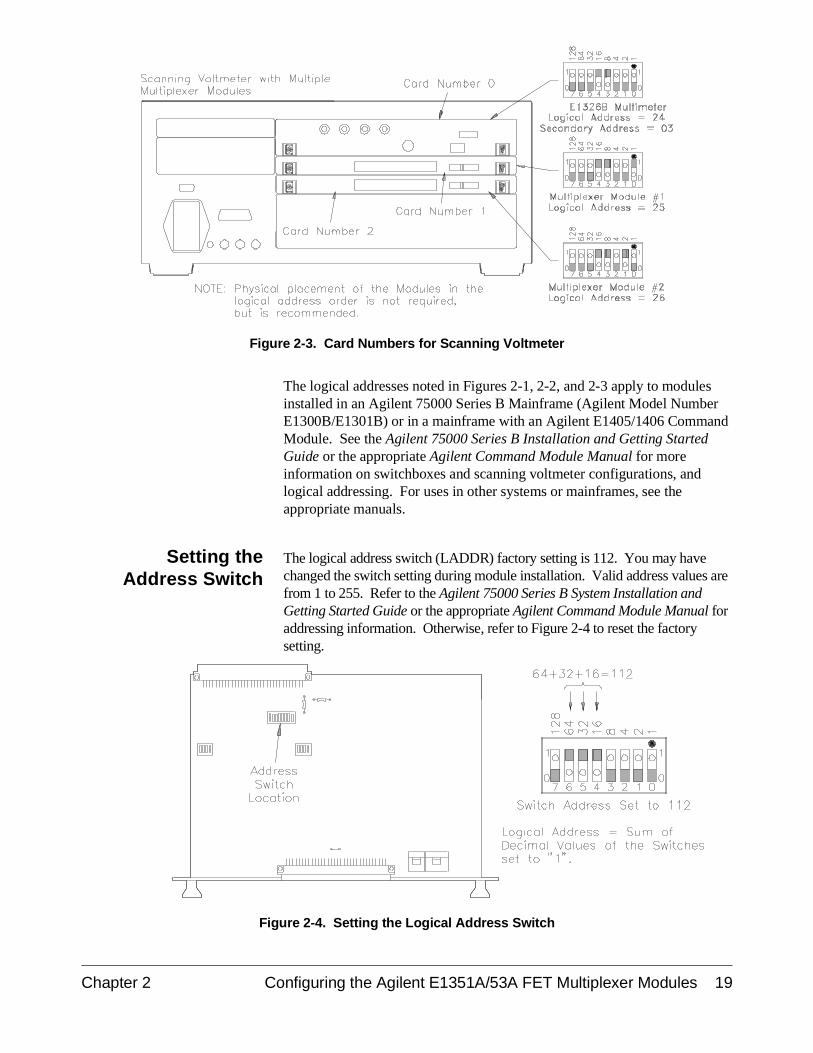
The logical addresses noted in Figures 2-1, 2-2, and 2-3 apply to modulesinstalled in an Agilent 75000 Series B Mainframe (Agilent Model NumberE1300B/E1301B) or in a mainframe with an Agilent E1405/1406 CommandModule. See the Agilent 75000 Series B Installation and Getting StartedGuide or the appropriate Agilent Command Module Manual for moreinformation on switchboxes and scanning voltmeter configurations, andlogical addressing. For uses in other systems or mainframes, see theappropriate manuals.
Setting theAddress Switch
The logical address switch (LADDR) factory setting is 112. You may havechanged the switch setting during module installation. Valid address values arefrom 1 to 255. Refer to the Agilent 75000 Series B System Installation andGetting Started Guide or the appropriate Agilent Command Module Manual foraddressing information. Otherwise, refer to Figure 2-4 to reset the factorysetting.
Figure 2-3. Card Numbers for Scanning Voltmeter
Figure 2-4. Setting the Logical Address Switch
Chapter 2 Configuring the Agilent E1351A/53A FET Multiplexer Modules 19
Selecting the Interrupt Line Number
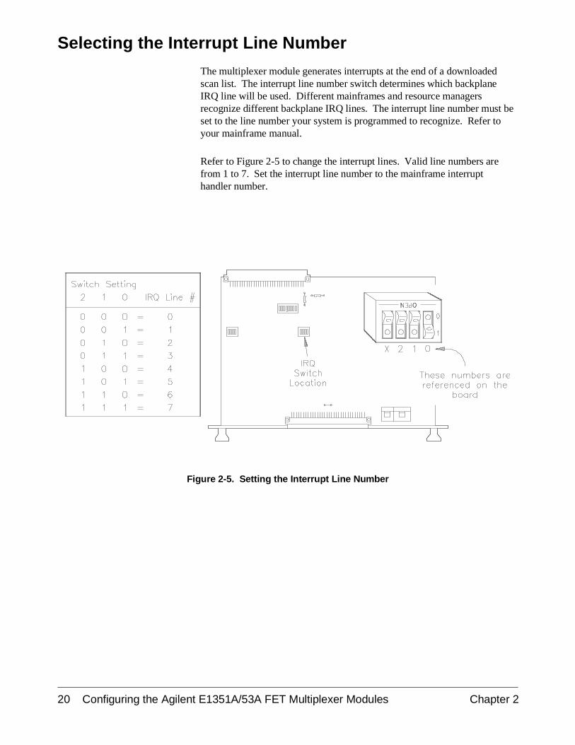
The multiplexer module generates interrupts at the end of a downloadedscan list. The interrupt line number switch determines which backplaneIRQ line will be used. Different mainframes and resource managersrecognize different backplane IRQ lines. The interrupt line number must beset to the line number your system is programmed to recognize. Refer toyour mainframe manual.
Refer to Figure 2-5 to change the interrupt lines. Valid line numbers arefrom 1 to 7. Set the interrupt line number to the mainframe interrupthandler number.
Figure 2-5. Setting the Interrupt Line Number
20 Configuring the Agilent E1351A/53A FET Multiplexer Modules Chapter 2
Setting the Card ID Switch
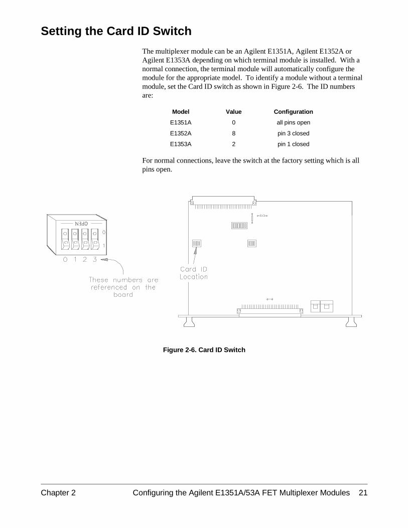
The multiplexer module can be an Agilent E1351A, Agilent E1352A orAgilent E1353A depending on which terminal module is installed. With anormal connection, the terminal module will automatically configure themodule for the appropriate model. To identify a module without a terminalmodule, set the Card ID switch as shown in Figure 2-6. The ID numbersare:
Model Value Configuration
E1351A 0 all pins open
E1352A 8 pin 3 closed
E1353A 2 pin 1 closed
For normal connections, leave the switch at the factory setting which is allpins open.
Figure 2-6. Card ID Switch
Chapter 2 Configuring the Agilent E1351A/53A FET Multiplexer Modules 21
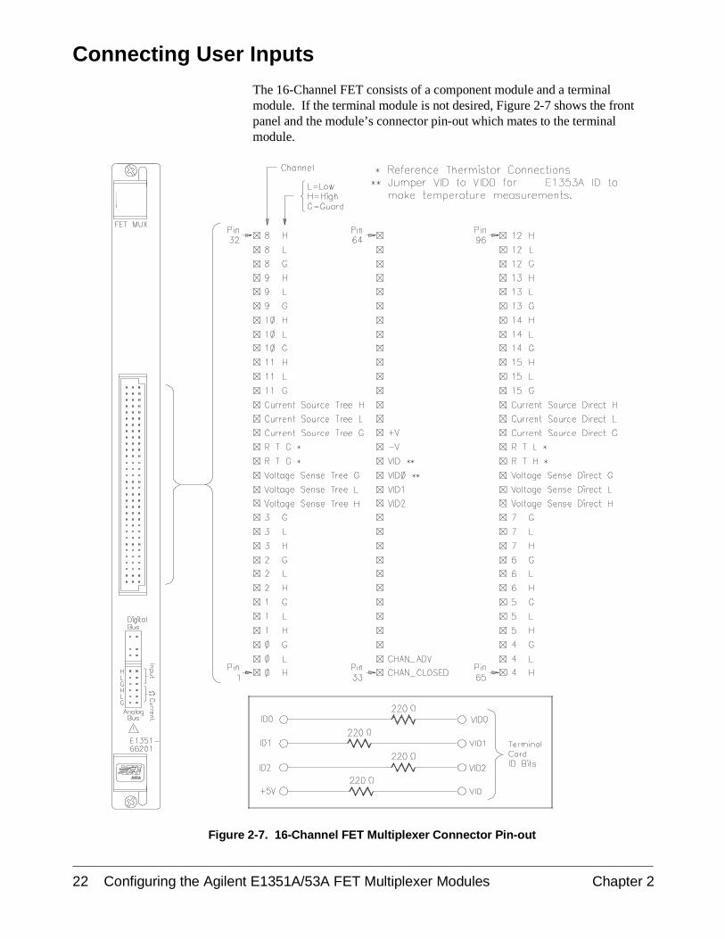
Connecting User Inputs
The 16-Channel FET consists of a component module and a terminalmodule. If the terminal module is not desired, Figure 2-7 shows the frontpanel and the module’s connector pin-out which mates to the terminalmodule.
Figure 2-7. 16-Channel FET Multiplexer Connector Pin-out
22 Configuring the Agilent E1351A/53A FET Multiplexer Modules Chapter 2
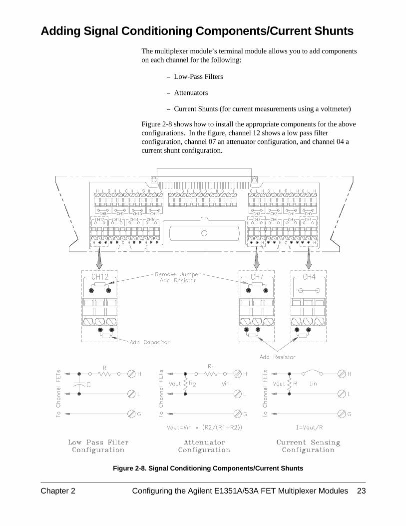
Adding Signal Conditioning Components/Current Shunts
The multiplexer module’s terminal module allows you to add componentson each channel for the following:
– Low-Pass Filters
– Attenuators
– Current Shunts (for current measurements using a voltmeter)
Figure 2-8 shows how to install the appropriate components for the aboveconfigurations. In the figure, channel 12 shows a low pass filterconfiguration, channel 07 an attenuator configuration, and channel 04 acurrent shunt configuration.
Figure 2-8. Signal Conditioning Components/Current Shunts
Chapter 2 Configuring the Agilent E1351A/53A FET Multiplexer Modules 23
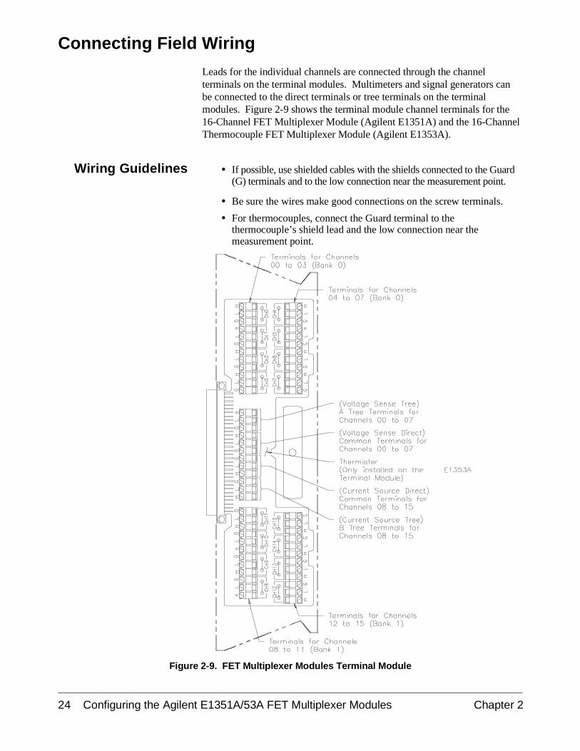
Connecting Field Wiring
Leads for the individual channels are connected through the channelterminals on the terminal modules. Multimeters and signal generators canbe connected to the direct terminals or tree terminals on the terminalmodules. Figure 2-9 shows the terminal module channel terminals for the16-Channel FET Multiplexer Module (Agilent E1351A) and the 16-ChannelThermocouple FET Multiplexer Module (Agilent E1353A).
Wiring Guidelines • If possible, use shielded cables with the shields connected to the Guard(G) terminals and to the low connection near the measurement point.
• Be sure the wires make good connections on the screw terminals.
• For thermocouples, connect the Guard terminal to thethermocouple’s shield lead and the low connection near themeasurement point.
Figure 2-9. FET Multiplexer Modules Terminal Module
24 Configuring the Agilent E1351A/53A FET Multiplexer Modules Chapter 2
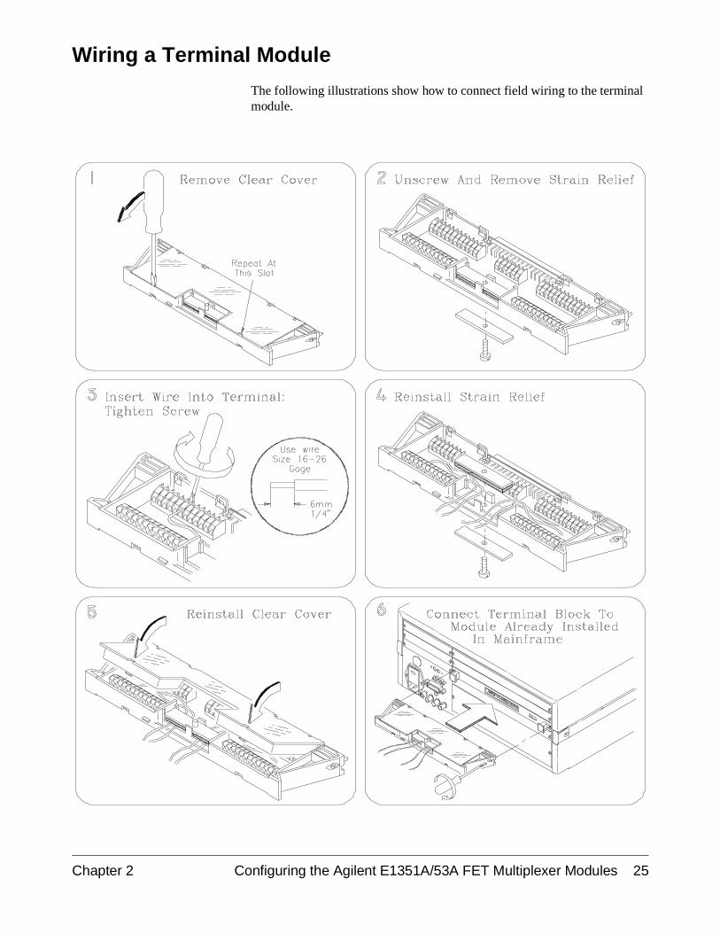
Wiring a Terminal Module
The following illustrations show how to connect field wiring to the terminalmodule.
Chapter 2 Configuring the Agilent E1351A/53A FET Multiplexer Modules 25
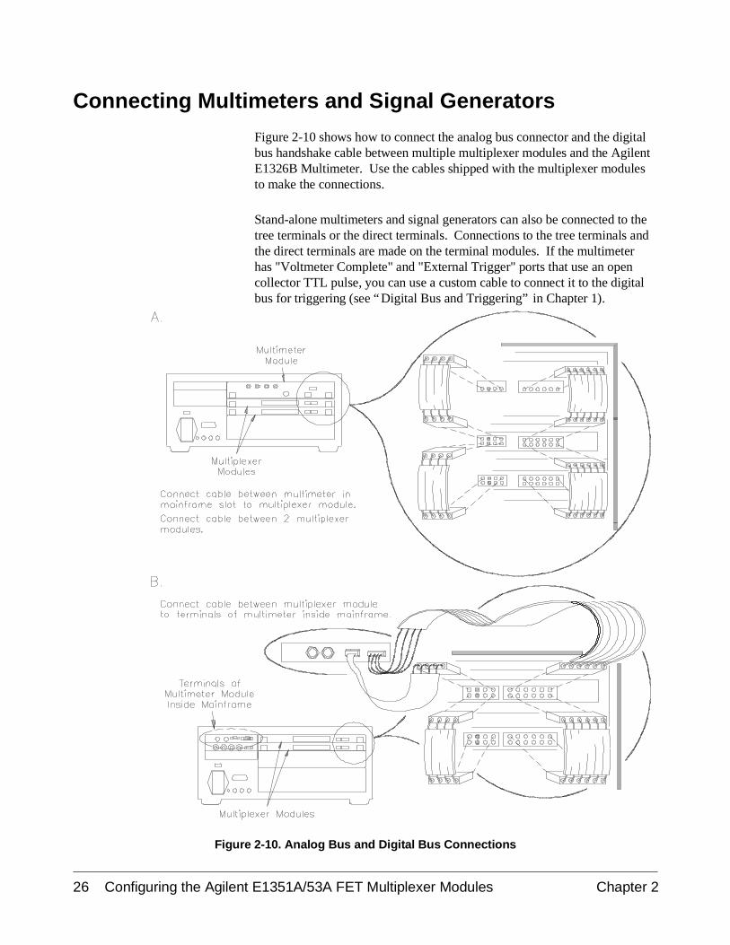
Connecting Multimeters and Signal Generators
Figure 2-10 shows how to connect the analog bus connector and the digitalbus handshake cable between multiple multiplexer modules and the AgilentE1326B Multimeter. Use the cables shipped with the multiplexer modulesto make the connections.
Stand-alone multimeters and signal generators can also be connected to thetree terminals or the direct terminals. Connections to the tree terminals andthe direct terminals are made on the terminal modules. If the multimeterhas "Voltmeter Complete" and "External Trigger" ports that use an opencollector TTL pulse, you can use a custom cable to connect it to the digitalbus for triggering (see “Digital Bus and Triggering” in Chapter 1).
Figure 2-10. Analog Bus and Digital Bus Connections
26 Configuring the Agilent E1351A/53A FET Multiplexer Modules Chapter 2
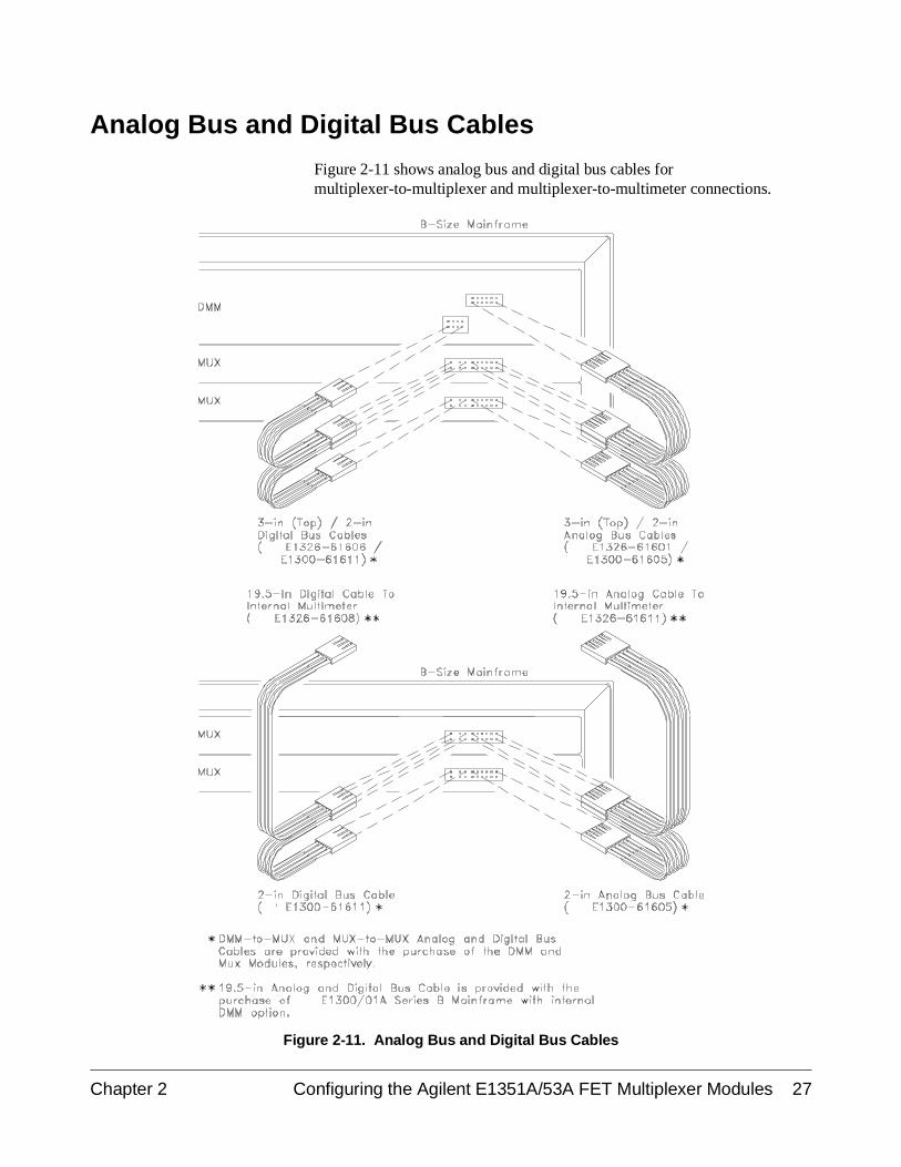
Analog Bus and Digital Bus Cables
Figure 2-11 shows analog bus and digital bus cables formultiplexer-to-multiplexer and multiplexer-to-multimeter connections.
Figure 2-11. Analog Bus and Digital Bus Cables
Chapter 2 Configuring the Agilent E1351A/53A FET Multiplexer Modules 27

Notes
28 Configuring the Agilent E1351A/53A FET Multiplexer Modules Chapter 2
Chapter 3Using the Agilent E1351A/53A FET
Multiplexer Modules
Using This Chapter
This chapter uses some typical examples to show how to use the16-Channel FET and 16-Channel Thermocouple FET Multiplexer Modules.Refer to Chapter 4, “Understanding the Agilent E1351A/53A FETMultiplexers” for further information. This chapter contains the followingsections:
• Selecting Channels . . . . . . . . . . . . . . . . . . . . . . . . . . . . . . . . . Page 29• Multiplexer Commands . . . . . . . . . . . . . . . . . . . . . . . . . . . . . Page 31• Connecting Switchbox Channels to Direct
Terminals . . . . . . . . . . . . . . . . . . . . . . . . . . . . . . . . . . . . Page 32• Connecting Switchbox Channels to Tree Terminals for
Making Measurements . . . . . . . . . . . . . . . . . . . . . . . . . . Page 34• Scanning a Range of Switchbox Channels . . . . . . . . . . . . . . Page 36• Downloading a Scan List . . . . . . . . . . . . . . . . . . . . . . . . . . . . Page 39• Scanning a Switchbox without a Downloaded
Scan List . . . . . . . . . . . . . . . . . . . . . . . . . . . . . . . . . . . . . Page 40• Scanning a Switchbox with a Downloaded
Scan List . . . . . . . . . . . . . . . . . . . . . . . . . . . . . . . . . . . . . Page 41• Scanning Voltmeter Configuration with
Agilent E1326B . . . . . . . . . . . . . . . . . . . . . . . . . . . . . . . Page 42• Measuring Temperature Using Thermocouples
(Agilent E1353A Module only) . . . . . . . . . . . . . . . . . . . Page 43
Selecting Channels
Individual channels within a module or multiple-module instrument areselected with the SCAN <channel_list> or OPEN and CLOSe<channel_list> commands. OPEN and CLOSe <channel_list> immediatelyopens/closes the specified channel. The SCAN <channel_list> commandcreates a scanning list which can be downloaded into RAM on each module.The INITiate command closes the first channel on the scan list, and theselected trigger mode advances the rest of the channels.
The FET Multiplexer Module uses break-before-make logic so that a closedchannel is opened before the next channel is closed. Only one channel canbe closed at any given time on the FET multiplexer. The only exception isin SCAN:MODE FRES (4-wire resistance measurements). You can,however, have a channel closed on two different modules in the sameinstrument.
Chapter 3 Using the Agilent E1351A/53A FET Multiplexer Modules 29

To address specific channels within a multiplexer module in a switchbox orscanning voltmeter configuration, you must send the appropriate SCPIcommand string with a specified card number (cc) and channel number(nn). The card number refers to the multiplexer module within a switchboxor scanning voltmeter configuration. The multiplexer module with thelowest logical address in a VXIbus instrument is card number 01, and thenext consecutively numbered multiplexer module is card number 02. If youhave more than one switchbox or scanning voltmeter configuration, the cardnumbering sequence starts at 01 for each configuration. A channel addressis, therefore, a four digit number (ccnn). For channel 07 on card 02 theaddress is 0207. You can delete leading zeros, so 207 is also a validchannel address. The channel address <channel_list> is in the form:
• (@ccnn) for a single channel;
• (@ccnn,ccnn) for multiple channels;
• (@ccnn:ccnn) for sequential channels;
• (@ccnn:ccnn,ccnn:ccnn) for groups of sequential channels.
The OPEN and CLOSe commands should only be used with thesingle-channel format and for one unique application of themultiple-channel format. You can close a channel on two different cards inthe same instrument (e.g., 102 and 208) at the same time. You cannot closetwo channels on the same card at the same time (102 and 108). Closing achannel automatically opens all other channels on that card.
CLOSe (@102,208,309) Closes 02 on card 1, 08 on card 2and 09 on card 3.
CLOSe (@103,204) Opens 102 and 208, closes 103and 204; 309 left closed.
30 Using the Agilent E1351A/53A FET Multiplexer Modules Chapter 3
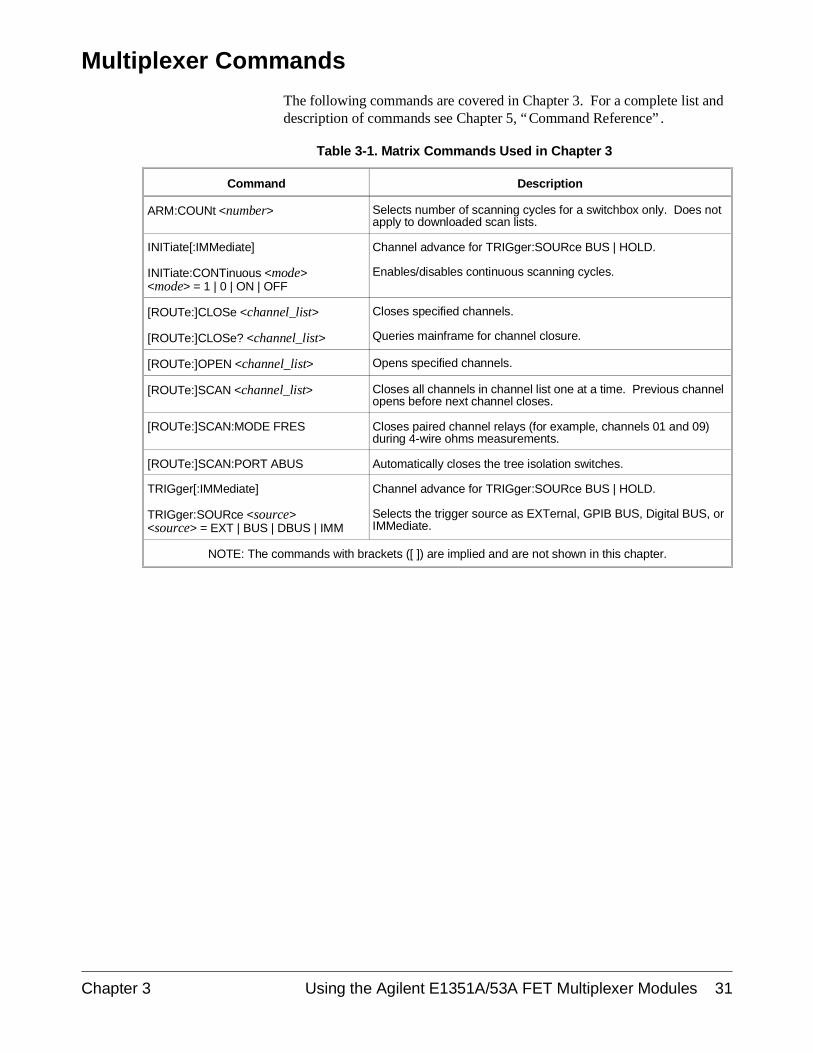
Multiplexer Commands
The following commands are covered in Chapter 3. For a complete list anddescription of commands see Chapter 5, “Command Reference” .
Table 3-1. Matrix Commands Used in Chapter 3
Command Description
ARM:COUNt <number> Selects number of scanning cycles for a switchbox only. Does notapply to downloaded scan lists.
INITiate[:IMMediate]
INITiate:CONTinuous <mode><mode> = 1 | 0 | ON | OFF
Channel advance for TRIGger:SOURce BUS | HOLD.
Enables/disables continuous scanning cycles.
[ROUTe:]CLOSe <channel_list>
[ROUTe:]CLOSe? <channel_list>
Closes specified channels.
Queries mainframe for channel closure.
[ROUTe:]OPEN <channel_list> Opens specified channels.
[ROUTe:]SCAN <channel_list> Closes all channels in channel list one at a time. Previous channelopens before next channel closes.
[ROUTe:]SCAN:MODE FRES Closes paired channel relays (for example, channels 01 and 09)during 4-wire ohms measurements.
[ROUTe:]SCAN:PORT ABUS Automatically closes the tree isolation switches.
TRIGger[:IMMediate]
TRIGger:SOURce <source><source> = EXT | BUS | DBUS | IMM
Channel advance for TRIGger:SOURce BUS | HOLD.
Selects the trigger source as EXTernal, GPIB BUS, Digital BUS, orIMMediate.
NOTE: The commands with brackets ([ ]) are implied and are not shown in this chapter.
Chapter 3 Using the Agilent E1351A/53A FET Multiplexer Modules 31
Connecting Switchbox Channels to Direct Terminals
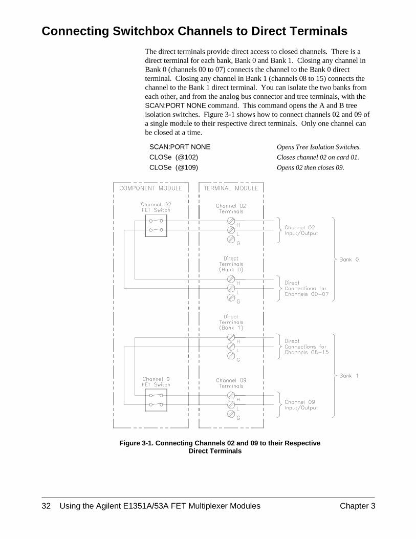
The direct terminals provide direct access to closed channels. There is adirect terminal for each bank, Bank 0 and Bank 1. Closing any channel inBank 0 (channels 00 to 07) connects the channel to the Bank 0 directterminal. Closing any channel in Bank 1 (channels 08 to 15) connects thechannel to the Bank 1 direct terminal. You can isolate the two banks fromeach other, and from the analog bus connector and tree terminals, with theSCAN:PORT NONE command. This command opens the A and B treeisolation switches. Figure 3-1 shows how to connect channels 02 and 09 ofa single module to their respective direct terminals. Only one channel canbe closed at a time.
SCAN:PORT NONE Opens Tree Isolation Switches.
CLOSe (@102) Closes channel 02 on card 01.
CLOSe (@109) Opens 02 then closes 09.
Figure 3-1. Connecting Channels 02 and 09 to their RespectiveDirect Terminals
32 Using the Agilent E1351A/53A FET Multiplexer Modules Chapter 3
Comments Isolation. The direct terminals provide a more accurate measurement thanthe tree terminals or the analog bus connector as the signal does not have totravel through the extra FET switches. The SCAN:PORT NONE commandopens the tree isolation switches and isolates the direct terminals from thetree terminals and the analog bus connector.
The default value of SCAN:PORT is NONE for reset and power-on. If youhave not specified a different SCAN:PORT since reset or power-on, you donot need to execute this command. You can also use the direct terminalswith SCAN:PORT ABUS. The signal for a given closed channel will thenbe available at the direct terminal for that bank, the A tree terminal and theanalog bus connector.
Closing Channels. The FET multiplexer module only allows one channelper card to be closed at a time, except for SCAN:MODE FRES (4-wireresistance measurements) where two channels are closed. You can close achannel on two different cards in the same instrument at the same time.
The SCAN <channel_list> command allows you to specify a list of channelsto be closed sequentially. The FET multiplexer module uses abreak-before-make procedure, so closed channels are opened before thenext one on the list is closed. The channels are advanced according to theTRIGger mode selected.
Query Open/Closed Channels. The CLOSe? <channel_list> and OPEN?<channel_list> commands determine if the channel(s) in the channel list areopen or closed, respectively. (The query command does not determine if, inthe event of a hardware failure, the channel remains open/closed.) Forexample, to determine if channel 109 is closed, execute:
CLOS? (@109)
A response of "1" indicates the channel is closed, and a "0" indicates thechannel is open. The reverse is true for the OPEN? <channel_list>command. The response for the OPEN? and CLOSe? commands are:
CLOS? 1 = Closed0 = Open
OPEN? 1 = Open0 = Closed
To find out which channel on a card is closed, use a channel list for the card.
CLOS? (@100:115)
and enter the response into a string variable. If channel 09 is closed, theresponse will be:
0,0,0,0,0,0,0,0,0,1,0,0,0,0,0,0
NOTE: You must read the response after sending a query command orthe switchbox will generate an error.
Chapter 3 Using the Agilent E1351A/53A FET Multiplexer Modules 33
Connecting Switchbox Channels to Tree Terminals forMaking Measurements
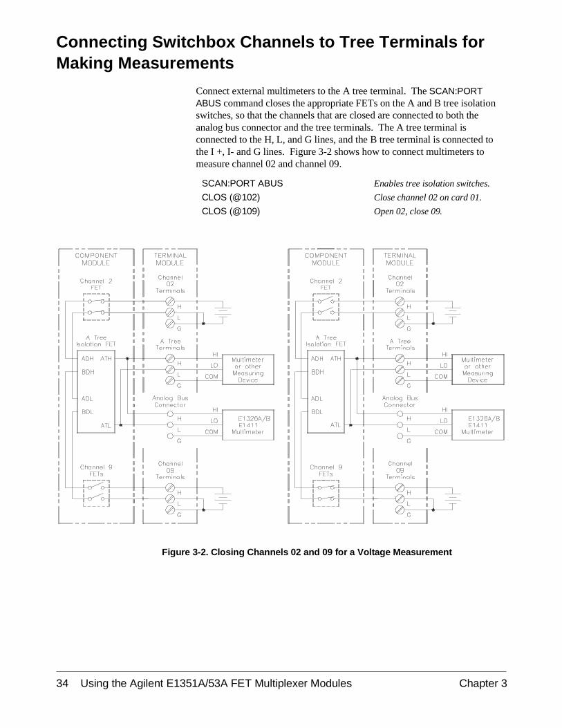
Connect external multimeters to the A tree terminal. The SCAN:PORTABUS command closes the appropriate FETs on the A and B tree isolationswitches, so that the channels that are closed are connected to both theanalog bus connector and the tree terminals. The A tree terminal isconnected to the H, L, and G lines, and the B tree terminal is connected tothe I +, I- and G lines. Figure 3-2 shows how to connect multimeters tomeasure channel 02 and channel 09.
SCAN:PORT ABUS Enables tree isolation switches.
CLOS (@102) Close channel 02 on card 01.
CLOS (@109) Open 02, close 09.
Figure 3-2. Closing Channels 02 and 09 for a Voltage Measurement
34 Using the Agilent E1351A/53A FET Multiplexer Modules Chapter 3
Example: ConnectChannels 02 and 10 to
Tree Terminals for4-Wire Ohms
Measurement
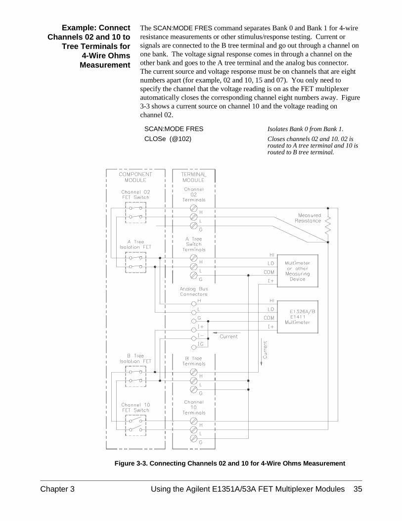
The SCAN:MODE FRES command separates Bank 0 and Bank 1 for 4-wireresistance measurements or other stimulus/response testing. Current orsignals are connected to the B tree terminal and go out through a channel onone bank. The voltage signal response comes in through a channel on theother bank and goes to the A tree terminal and the analog bus connector.The current source and voltage response must be on channels that are eightnumbers apart (for example, 02 and 10, 15 and 07). You only need tospecify the channel that the voltage reading is on as the FET multiplexerautomatically closes the corresponding channel eight numbers away. Figure3-3 shows a current source on channel 10 and the voltage reading onchannel 02.
SCAN:MODE FRES Isolates Bank 0 from Bank 1.
CLOSe (@102) Closes channels 02 and 10. 02 isrouted to A tree terminal and 10 isrouted to B tree terminal.
Figure 3-3. Connecting Channels 02 and 10 for 4-Wire Ohms Measurement
Chapter 3 Using the Agilent E1351A/53A FET Multiplexer Modules 35
Scanning a Range of Switchbox Channels
You can scan a range of channels of a switchbox consisting of single ormultiple multiplexer modules. Scanning involves sequentially closing eachchannel on a range of specified channels. The selected TRIGger modedetermines when the channel closure will advance. During scanning, theFET which was previously closed opens before the next FET closes.
You can use any of the TRIGger modes to advance the channel list.TRIGger:SOURce EXTernal requires an external trigger source to be connectedto the Agilent E1300/1301 Mainframe "Event In" port. For computercontrolled or GPIB triggering (TRIGger or *TRG) use TRIGger:SOURce BUS.The OUTput ON command enables the mainframe’s "Trig Out" port tosynchronize multimeters when not in the TRIGger:SOURce DBUS | IMMmodes.
For the fastest scan rate (up to 100 K switches/sec.) use TRIGger:SOURceDBUS. Use a custom cable (see “Digital Bus and Triggering” on page 15)to connect the multimeter handshake lines (Voltmeter Complete andExternal Trigger) to the multiplexer digital bus.
Example: MakingVoltage Measurements
by Scanning
Figures 3-4 and 3-5, and the following commands, show how to makevoltage measurements by performing a single scanning cycle of all channelson two multiplexer modules in a single switchbox. In the example, the:
• A Tree Terminals of each terminal module connect to each other andto the multimeter in Figure 3-5. To connect the A tree terminals toeach other, use either the analog bus cables (shown in Figures 2-10and 2-11) or wire the terminals together between the terminalmodules.
• GPIB Bus trigger command advances the switchbox channel list.
• Agilent E1300B/E1301B Mainframe’s "Trig Out" pulsesynchronizes the switchbox with the multimeter.
• Multimeter GPIB select code is 7 and primary address is 22.
• Switchbox GPIB select code is 7, the GPIB primary address is 09,and the GPIB secondary address is 14.
• Computer is an HP Series 200/300 Computer with BASIC usingGPIB.
Enter and Execute:
10 OUTPUT 722;"TRIG EXT;DC 10" !Sets multimeter to externaltriggers and to measure dc volts
20 OUTPUT 70914;"OUTP ON" !Enables "Trig Out" port
30 OUTPUT 70914;"TRIG:SOUR BUS" !Sets switchbox to receive bustriggers
40 OUTPUT 70914;"SCAN:MODE VOLT"!Setup switchbox to measurevoltage
50 OUTPUT 70914;"SCAN:PORT ABUS"!Closes the appropriate treeisolation switches while scanning;
36 Using the Agilent E1351A/53A FET Multiplexer Modules Chapter 3
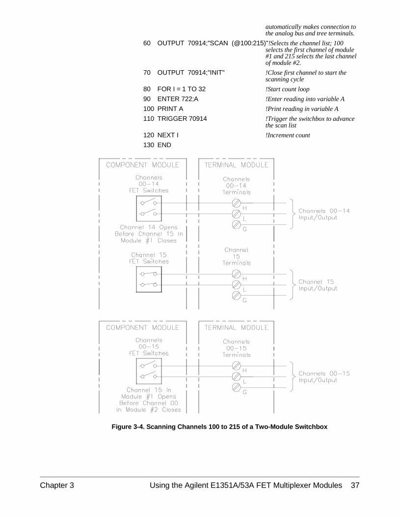
automatically makes connection tothe analog bus and tree terminals.
60 OUTPUT 70914;"SCAN (@100:215)"!Selects the channel list; 100selects the first channel of module#1 and 215 selects the last channelof module #2.
70 OUTPUT 70914;"INIT" !Close first channel to start thescanning cycle
80 FOR I = 1 TO 32 !Start count loop
90 ENTER 722;A !Enter reading into variable A
100 PRINT A !Print reading in variable A
110 TRIGGER 70914 !Trigger the switchbox to advancethe scan list
120 NEXT I !Increment count
130 END
Figure 3-4. Scanning Channels 100 to 215 of a Two-Module Switchbox
Chapter 3 Using the Agilent E1351A/53A FET Multiplexer Modules 37
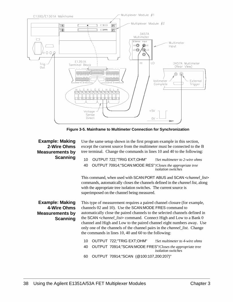
Example: Making2-Wire Ohms
Measurements byScanning
Use the same setup shown in the first program example in this section,except the current source from the multimeter must be connected to the Btree terminal. Change the commands in lines 10 and 40 to the following:
10 OUTPUT 722;"TRIG EXT;OHM" !Set multimeter to 2-wire ohms
40 OUTPUT 70914;"SCAN:MODE RES"!Closes the appropriate treeisolation switches
This command, when used with SCAN:PORT ABUS and SCAN <channel_list>commands, automatically closes the channels defined in the channel list, alongwith the appropriate tree isolation switches. The current source issuperimposed on the channel being measured.
Example: Making4-Wire Ohms
Measurements byScanning
This type of measurement requires a paired channel closure (for example,channels 02 and 10). Use the SCAN:MODE FRES command toautomatically close the paired channels to the selected channels defined inthe SCAN <channel_list> command. Connect High and Low to a Bank 0channel and High and Low to the paired channel eight numbers away. Useonly one of the channels of the channel pairs in the channel_list. Changethe commands in lines 10, 40 and 60 to the following:
10 OUTPUT 722;"TRIG EXT;OHM" !Set multimeter to 4-wire ohms
40 OUTPUT 70914;"SCAN:MODE FRES"!Closes the appropriate treeisolation switches
60 OUTPUT 70914;"SCAN (@100:107,200:207)"
Figure 3-5. Mainframe to Multimeter Connection for Synchronization
38 Using the Agilent E1351A/53A FET Multiplexer Modules Chapter 3
Example: MakingMultiple Scans
The ARM:COUNt <number> command selects multiple scanning cycles forswitchboxes with non-downloaded scans. It does not apply when theTRIGger:SOURce is DBUS or IMMediate.
Add the command before the SCAN <channel_list> in the first programexample in this section. When the last channel in a channel list is closed,the pointer is reset back to the beginning of the channel list. The nexttrigger opens the last channel and closes the first one. This continues for thespecified number of cycles.
59 OUTPUT 70914;"ARM:COUN 10" !Enables 10 scanning cycles
60 OUTPUT 70914;"SCAN (@100:215)"!Sets scan list
80 FOR I = 1 TO 320
Example: MakingContinuous Scans
The INITiate:CONTinuous ON command selects continuous scanning cycles(INIT:CONT OFF disables continuous scanning cycles). Add the commandto the first program example in this section, as follows:
59 OUTPUT 70914;"INIT:CONT ON" !Enables continuous scanningcycles
60 OUTPUT 70914;"SCAN (@100:215)"!Sets scan list
80 FOR I = 1 TO X !Set the number of measurementsdesired
Comments Scanning consists of six steps:
• Connecting the multimeter to the switchbox• Selecting the SCAN:MODE• Selecting the SCAN:PORT• Selecting the TRIGger:SOURce• Specifying the SCAN <channel_list>• Starting the scan (INIT or TRIG[:IMMediate])
Downloading a Scan List
The FET Multiplexer Module is primarily designed to be used as ahigh-speed scanning switchbox or scanning voltmeter. To enable it to make100,000 connections per second, the SCAN <channel_list> scanning list isdownloaded into RAM on the module. This download takes placeautomatically when you use TRIGger:SOURce DBUS or TRIGger:SOURceIMM. For a multiple-module switchbox, the entire scanning list isdownloaded to each module. The channels are advanced to the next channelin the channel list without any direct intervention by the mainframe CPUduring the scan.
The scan list is not downloaded for a switchbox or scanning voltmeter thatcombines both FET and relay multiplexer modules, or forTRIGger:SOURce BUS | EXT | HOLD. The channel closings are controlledby the mainframe CPU. Also, the ARM:COUNt <number> command doesnot apply to downloaded scan lists. You can use INITiate:CONTinuous ONfor continuous scanning with downloaded scan lists.
Chapter 3 Using the Agilent E1351A/53A FET Multiplexer Modules 39
Scanning a Switchbox without a Downloaded Scan List
This example shows a FET switchbox connected to a multimeter with theanalog bus cable. The switchbox and multimeter are separate VXIbusinstruments. The multimeter has a secondary address of 03, and theswitchbox has a secondary address of 04. The multiplexer is triggered bythe *TRG command. OUTPut ON is enabled, and the multimeter istriggered by the OUTPut ON trigger to its "External Trigger" port. Thefollowing program illustrates the procedures:
10 DIM Rdgs(1:16) !Dimension array to store readings
20 OUTPUT 70903;"*RST;*OPC?" !Clear the multimeter; *OPC?ensures reset is completed beforeprogram continues
30 ENTER 70903;A
40 OUTPUT 70903;"*CLS"
50 OUTPUT 70904;"*RST" !Reset multiplexer
60 OUTPUT 70904;"*CLS"
70 OUTPUT 70903;"CONF:VOLT:DC 58.1"!Configure the multimeter
80 OUTPUT 70903;"TRIG:SOUR EXT" !External trigger source
90 OUTPUT 70903;"TRIG:COUN 16" !Set for 16 triggers
100 OUTPUT 70903;"INIT" !Initialize multimeter wait fortrigger
110 OUTPUT 70904;"TRIG:SOUR BUS" !Trigger on *TRG command
120 OUTPUT 70904;"SCAN:MODE VOLT"!Configure for voltage
130 OUTPUT 70904;"SCAN:PORT ABUS"!Enables analog bus
140 OUTPUT 70904;"SCAN (@100:115)"!Enter scan list
150 OUTPUT 70904;"OUTP ON" !Enable mainframe trig out port
160 OUTPUT 70904;"INIT" !Close first channel
170 FOR I = 1 TO 16 !16 channels
180 OUTPUT 70904;"*TRG" !Trigger for channel advance
190 WAIT .25 !Allow time for measurementbefore next advance
200 NEXT I !Increment counter
210 OUTPUT 70903;"FETC?" !Multimeter retrieves readingsfrom mainframe memory whenscan completes
220 ENTER 70903;Rdgs(*) !Put readings in array
230 PRINT Rdgs(*) !Print
240 END
40 Using the Agilent E1351A/53A FET Multiplexer Modules Chapter 3

Scanning a Switchbox with a Downloaded Scan List
This example shows a FET switchbox connected to multimeter with theanalog bus cable and the digital bus cable. The switchbox and multimeterare separate VXIbus instruments. The multimeter has a secondary addressof 03, and the switchbox has a secondary address of 04. The triggering isthrough the digital bus handshake lines, so the scan list is downloaded. Thefollowing program illustrates the procedures:
10 DIM Rdgs(1:16) !Dimension array to store readings
20 OUTPUT 70903,"*RST,*OPC?" !Clear the multimeter; *OPC?ensures reset is completed beforeprogram continues
30 ENTER 70903;A
40 OUTPUT 70903;"*CLS"
50 OUTPUT 70904;"*RST" !Reset multiplexer
60 OUTPUT 70904;"*CLS"
70 OUTPUT 70903;"CONF:VOLT:DC 58.1"!Configure the multimeter
80 OUTPUT 70903;"TRIG:SOUR EXT" !External trigger source
90 OUTPUT 70903;"TRIG:COUN 16" !Set for 16 triggers
100 OUTPUT 70903;"INIT" !Initialize multimeter, wait fortrigger
110 OUTPUT 70904;"STAT:OPER:ENAB 256"!Enable operation complete bit
120 OUTPUT 70904;"TRIG:SOUR DBUS"!Digital bus triggers
130 OUTPUT 70904;"SCAN:MODE VOLT"!Configure for voltage
140 OUTPUT 70904;"SCAN:PORT ABUS"!Enables analog bus
150 OUTPUT 70904;"SETT:TIME MAX,(@100)"!Delay for signal to settle beforemultiplexer enables channel closedpulse
160 OUTPUT 70904;"SCAN (@100:131)"!Enter scan list
170 OUTPUT 70904;"INIT" !Close first channel
180 OUTPUT 70903;"FETC?" !Multimeter retrieves readingsfrom mainframe memory whenscan completes
190 ENTER 70903;Rdgs(*) !Put readings in array
200 PRINT Rdgs(*) !Print
210 END
Chapter 3 Using the Agilent E1351A/53A FET Multiplexer Modules 41
Scanning Voltmeter Configuration with Agilent E1326B
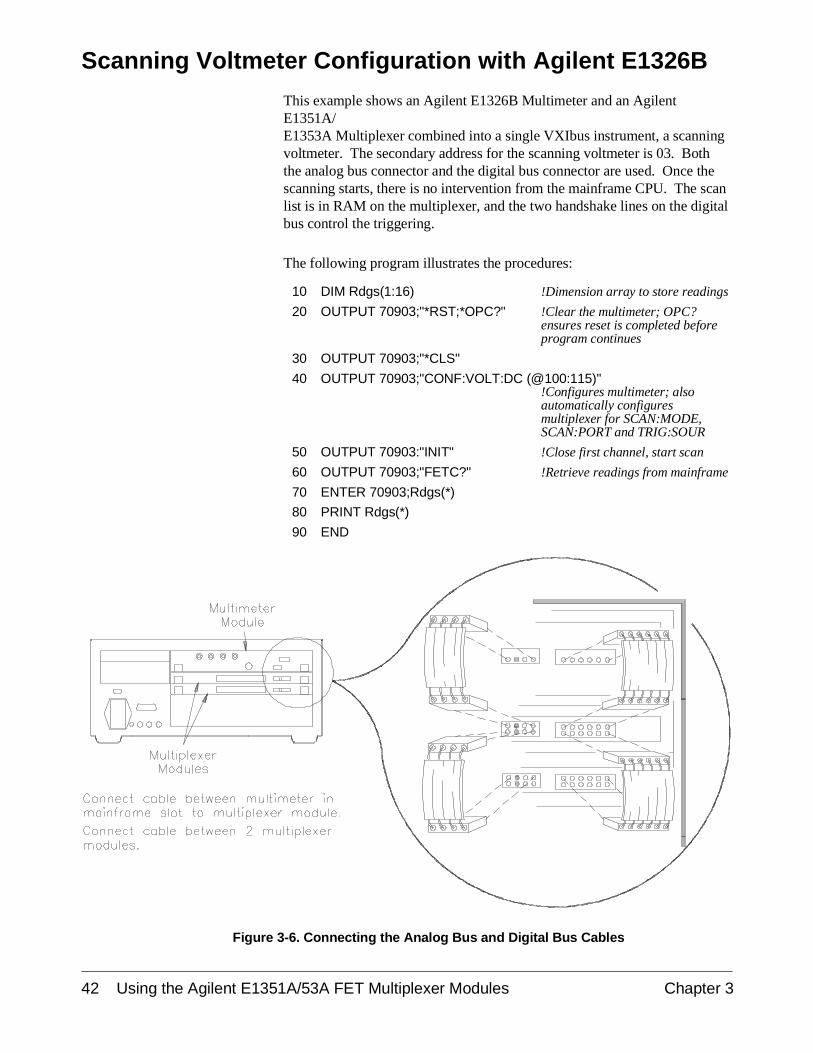
This example shows an Agilent E1326B Multimeter and an AgilentE1351A/E1353A Multiplexer combined into a single VXIbus instrument, a scanningvoltmeter. The secondary address for the scanning voltmeter is 03. Boththe analog bus connector and the digital bus connector are used. Once thescanning starts, there is no intervention from the mainframe CPU. The scanlist is in RAM on the multiplexer, and the two handshake lines on the digitalbus control the triggering.
The following program illustrates the procedures:
10 DIM Rdgs(1:16) !Dimension array to store readings
20 OUTPUT 70903;"*RST;*OPC?" !Clear the multimeter; OPC?ensures reset is completed beforeprogram continues
30 OUTPUT 70903;"*CLS"
40 OUTPUT 70903;"CONF:VOLT:DC (@100:115)"!Configures multimeter; alsoautomatically configuresmultiplexer for SCAN:MODE,SCAN:PORT and TRIG:SOUR
50 OUTPUT 70903:"INIT" !Close first channel, start scan
60 OUTPUT 70903;"FETC?" !Retrieve readings from mainframe
70 ENTER 70903;Rdgs(*)
80 PRINT Rdgs(*)
90 END
Figure 3-6. Connecting the Analog Bus and Digital Bus Cables
42 Using the Agilent E1351A/53A FET Multiplexer Modules Chapter 3
Measuring Temperature Using Thermocouples (Agilent E1353A Module only)
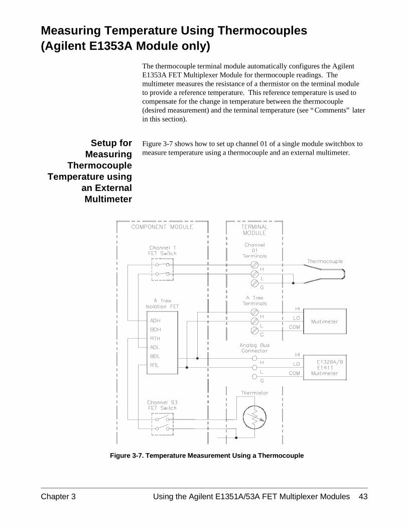
The thermocouple terminal module automatically configures the AgilentE1353A FET Multiplexer Module for thermocouple readings. Themultimeter measures the resistance of a thermistor on the terminal moduleto provide a reference temperature. This reference temperature is used tocompensate for the change in temperature between the thermocouple(desired measurement) and the terminal temperature (see “Comments” laterin this section).
Setup forMeasuring
ThermocoupleTemperature using
an ExternalMultimeter
Figure 3-7 shows how to set up channel 01 of a single module switchbox tomeasure temperature using a thermocouple and an external multimeter.
Figure 3-7. Temperature Measurement Using a Thermocouple
Chapter 3 Using the Agilent E1351A/53A FET Multiplexer Modules 43

Comments Measuring Temperature with the El326B/El411B Multimeters. TheAgilent E1326B/E1411B Multimeters can directly measure channels of singleor multiple multiplexer modules. The multimeter automatically calculates thecorrect temperature for the specific thermistor or thermocouple type used. Formore information, see the Agilent E1326B/E1411B Multimeter User’s Manual.
Thermocouple Compensated Measurements. The Agilent E1353A FETMultiplexer makes thermocouple compensated measurements. Thermocouplecompensation accounts for the temperature inside the multiplexer terminalmodule, which can affect the thermocouple reading. Thermocouplecompensated measurements are made with the Agilent E1326B/E1411B.More information on these types of measurements can be found in AgilentTechnologies Application Note 290, Practical Temperature Measurements.
High-Speed Temperature Measurements. High-speed temperaturemeasurements can be made by measuring the thermocouple voltage,compensating the reading, and then converting the voltage to a temperature.The instrument configuration used for these types of measurements mayinclude an E1326B/E1411B Multimeter and a FET multiplexer switchbox,or an external voltmeter used with the FET switchbox. The procedure forthese types of measurements is:
1. Measure the resistance of the thermistor (channel 93) on themultiplexer terminal module (CLOSe(@cc93)).
2. Measure the thermocouple voltage on the multiplexer channel.
3. Convert the thermistor resistance to a temperature using thefollowing equation:
t = 1.0 / (A + B * lnr + C * (lnr)3)calculate temperaturet = t - 273.15 convert Kelvin to Centigrade
where:
A = 0.00128463B = 0.00023625C = 9.2697E-8lnr = natural log of the measured thermistor resistance
A, B, and C are the curve-fitting constants for the multiplexer’s5K thermistor.
4. Convert the thermistor temperature (step 3) to a voltage using thereference table for the type of thermocouple used.
5. Subtract the voltage (step 4) from the thermocouple voltagemeasured in step 2. Convert the difference between the voltages to atemperature, again using the reference table for the type ofthermocouple used.
6. Add the temperature (step 5) to the thermistor temperature computedin step 3 to obtain the result of the thermocouple measurement.
44 Using the Agilent E1351A/53A FET Multiplexer Modules Chapter 3
Chapter 4Understanding the Agilent E1351A/53A FET
Multiplexer Modules
Using This Chapter
This chapter explains techniques to scan the channels of 16-Channel FETand 16-Channel Thermocouple FET Multiplexer Modules. This chaptercontains the following sections:
• Commands for Scanning Switchbox Channels . . . . . . . . . . . Page 45 • Using Scanning Trigger Sources . . . . . . . . . . . . . . . . . . . . . . Page 45• Using the Scan Complete Bit . . . . . . . . . . . . . . . . . . . . . . . . . Page 52
Commands for Scanning Switchbox Channels
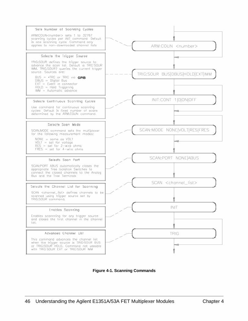
Scanning multiplexer channels consists of closing a set of channels, one at atime. The multiplexer has single, multiple, or continuous scanning modes.See Figure 4-1 for the different commands used in scanning.
Using Scanning Trigger Sources
The TRIGger:SOURce command specifies the source to advance thechannel list. Figure 4-2 shows the different trigger sources. TRIG:SOURDBUS uses the digital bus handshake lines. You can use the TRIG[:IMM]command to immediately advance the channel list while in the TRIG:SOURBUS or TRIG:SOUR HOLD mode. (Note that TRIG:SOUR IMM is not thesame as TRIG[:IMM].) To enable the Agilent E1300/E1301 Mainframe"Trig Out" port, use the OUTP ON command. The "Event In" mainframetrigger source is reserved with the TRIG:SOUR EXT command. "Trig Out"and "Event In" are mainframe resources, and can only be allocated to oneinstrument at a time.
Scanning withExternal
Instruments
The examples in this chapter show different ways to scan channels of aswitchbox in an Agilent E1300/E1301 Mainframe. The operation is similarto other Agilent VXIbus mainframes with Agilent command modules thathave "Trig Out" and "Event In" ports. The computer used in the examplesis an HP Series 200/300 used with BASIC as the program language. Thecomputer interfaces with the mainframe over GPIB. Assumed is an:
• GPIB select code of 7
• GPIB primary address of 09 for the Agilent E1300/E1301 Mainframe
• GPIB primary address of 22 for the Agilent 3457A Multimeter
• GPIB secondary address of 14 for the multiplexer module
Chapter 4 Understanding the Agilent E1351A/53A FET Multiplexer Modules 45
GPIB
Figure 4-1. Scanning Commands
46 Understanding the Agilent E1351A/53A FET Multiplexer Modules Chapter 4
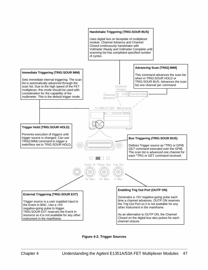
Handshake Triggering (TRIG:SOUR BUS)
Uses digital bus on faceplate of multiplexermodule. Channel Advance and ChannelClosed continuously handshake withVoltmeter Ready and Voltmeter Complete untilscanning list has completed specified numberof cycles.
Advancing Scan (TRIG[:IMM]
This command advances the scan listwhen in TRIG:SOUR HOLD orTRIG:SOUR BUS. Advances the scanlist one channel per command.
Bus Triggering (TRIG:SOUR BUS)
Defines Trigger source as *TRG or GPIBGET command executed over the GPIB.The scan list is advanced one channel foreach *TRG or GET command received.
Enabling Trig Out Port (OUTP ON)
Generates a +5V negative-going pulse eachtime a channel advances. OUTP ON reservesthe Trig Out Port so it is not available for anyother instrument in the mainframe.
As an alternative to OUTP ON, the ChannelClosed on the digital bus also pulses for eachchannel closure.
Immediate Triggering (TRIG:SOUR IMM)
Sets immediate internal triggering. The scanlist is automatically advanced through thescan list. Due to the high speed of the FETmultiplexer, this mode should be used withconsideration for the capability of themultimeter. This is the default trigger mode.
Trigger Hold (TRIG:SOUR HOLD)
Prevents execution of triggers untiltrigger source is changed. Can useTRIG[:IMM] command to trigger aswitchbox set to TRIG:SOUR HOLD.
External Triggering (TRIG:SOUR EXT)
Trigger source is a user supplied input tothe Event In BNC. Use a +5Vnegative-going pulse to trigger.TRIG:SOUR EXT reserves the Event Inresource so it is not available for any otherinstrument in the mainframe.
Figure 4-2. Trigger Sources
Chapter 4 Understanding the Agilent E1351A/53A FET Multiplexer Modules 47
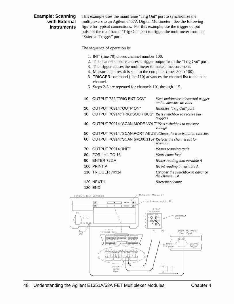
Example: Scanningwith ExternalInstruments
This example uses the mainframe "Trig Out" port to synchronize themultiplexers to an Agilent 3457A Digital Multimeter. See the followingfigure for typical connections. For this example, use the trigger outputpulse of the mainframe "Trig Out" port to trigger the multimeter from its"External Trigger" port.
The sequence of operation is:
1. INIT (line 70) closes channel number 100.2. The channel closure causes a trigger output from the "Trig Out" port.3. The trigger causes the multimeter to make a measurement.4. Measurement result is sent to the computer (lines 80 to 100).5. TRIGGER command (line 110) advances the channel list to the next
channel.6. Steps 2-5 are repeated for channels 101 through 115.
10 OUTPUT 722;"TRIG EXT;DCV" !Sets multimeter to external triggerand to measure dc volts
20 OUTPUT 70914;"OUTP ON" !Enables "Trig Out" port
30 OUTPUT 70914;"TRIG:SOUR BUS" !Sets switchbox to receive bustriggers
40 OUTPUT 70914;"SCAN:MODE VOLT"!Sets switchbox to measurevoltage
50 OUTPUT 70914;"SCAN:PORT ABUS"!Closes the tree isolation switches
60 OUTPUT 70914;"SCAN (@100:115)" !Selects the channel list forscanning
70 OUTPUT 70914;"INIT" !Starts scanning cycle
80 FOR I = 1 TO 16 !Start count loop
90 ENTER 722;A !Enter reading into variable A
100 PRINT A !Print reading in variable A
110 TRIGGER 70914 !Trigger the switchbox to advancethe channel list
120 NEXT I !Increment count
130 END
48 Understanding the Agilent E1351A/53A FET Multiplexer Modules Chapter 4
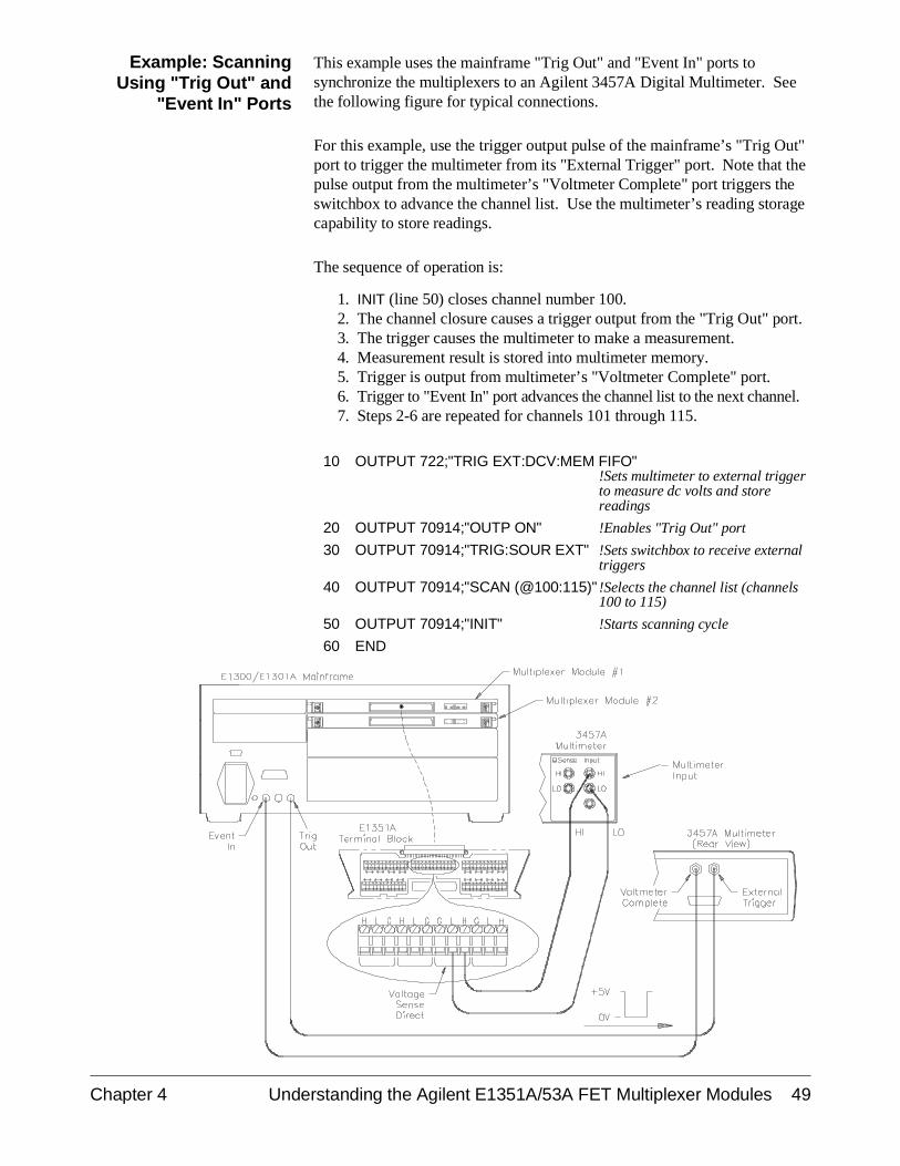
Example: ScanningUsing "Trig Out" and
"Event In" Ports
This example uses the mainframe "Trig Out" and "Event In" ports tosynchronize the multiplexers to an Agilent 3457A Digital Multimeter. Seethe following figure for typical connections.
For this example, use the trigger output pulse of the mainframe’s "Trig Out"port to trigger the multimeter from its "External Trigger" port. Note that thepulse output from the multimeter’s "Voltmeter Complete" port triggers theswitchbox to advance the channel list. Use the multimeter’s reading storagecapability to store readings.
The sequence of operation is:
1. INIT (line 50) closes channel number 100.2. The channel closure causes a trigger output from the "Trig Out" port.3. The trigger causes the multimeter to make a measurement.4. Measurement result is stored into multimeter memory.5. Trigger is output from multimeter’s "Voltmeter Complete" port.6. Trigger to "Event In" port advances the channel list to the next channel.7. Steps 2-6 are repeated for channels 101 through 115.
10 OUTPUT 722;"TRIG EXT:DCV:MEM FIFO"!Sets multimeter to external triggerto measure dc volts and storereadings
20 OUTPUT 70914;"OUTP ON" !Enables "Trig Out" port
30 OUTPUT 70914;"TRIG:SOUR EXT" !Sets switchbox to receive externaltriggers
40 OUTPUT 70914;"SCAN (@100:115)" !Selects the channel list (channels100 to 115)
50 OUTPUT 70914;"INIT" !Starts scanning cycle
60 END
Chapter 4 Understanding the Agilent E1351A/53A FET Multiplexer Modules 49
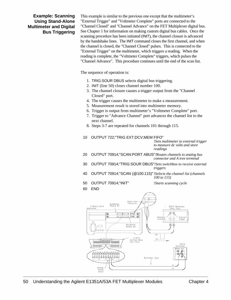
Example: ScanningUsing Stand-Alone
Multimeter and DigitalBus Triggering
This example is similar to the previous one except that the multimeter’s"External Trigger" and "Voltmeter Complete" ports are connected to the"Channel Closed" and "Channel Advance" on the FET Multiplexer digital bus.See Chapter 1 for information on making custom digital bus cables. Once thescanning procedure has been initiated (INIT), the channel closure is advancedby the handshake lines. The INIT command closes the first channel, and whenthe channel is closed, the "Channel Closed" pulses. This is connected to the"External Trigger" on the multimeter, which triggers a reading. When thereading is complete, the "Voltmeter Complete" triggers, which pulses the"Channel Advance". This procedure continues until the end of the scan list.
The sequence of operation is:
1. TRIG:SOUR DBUS selects digital bus triggering.2. INIT (line 50) closes channel number 100.3. The channel closure causes a trigger output from the "Channel
Closed" port.4. The trigger causes the multimeter to make a measurement.5. Measurement result is stored into multimeter memory.6. Trigger is output from multimeter’s "Voltmeter Complete" port.7. Trigger to "Advance Channel" port advances the channel list to the
next channel.8. Steps 3-7 are repeated for channels 101 through 115.
10 OUTPUT 722;"TRIG EXT;DCV;MEM FIFO"!Sets multimeter to external triggerto measure dc volts and storereadings
20 OUTPUT 70914;"SCAN:PORT ABUS"!Routes channels to analog busconnector and A tree terminal
30 OUTPUT 70914;"TRIG:SOUR DBUS"!Sets switchbox to receive externaltriggers
40 OUTPUT 70914;"SCAN (@100:115)" !Selects the channel list (channels100 to 115)
50 OUTPUT 70914;"INIT" !Starts scanning cycle
60 END
50 Understanding the Agilent E1351A/53A FET Multiplexer Modules Chapter 4
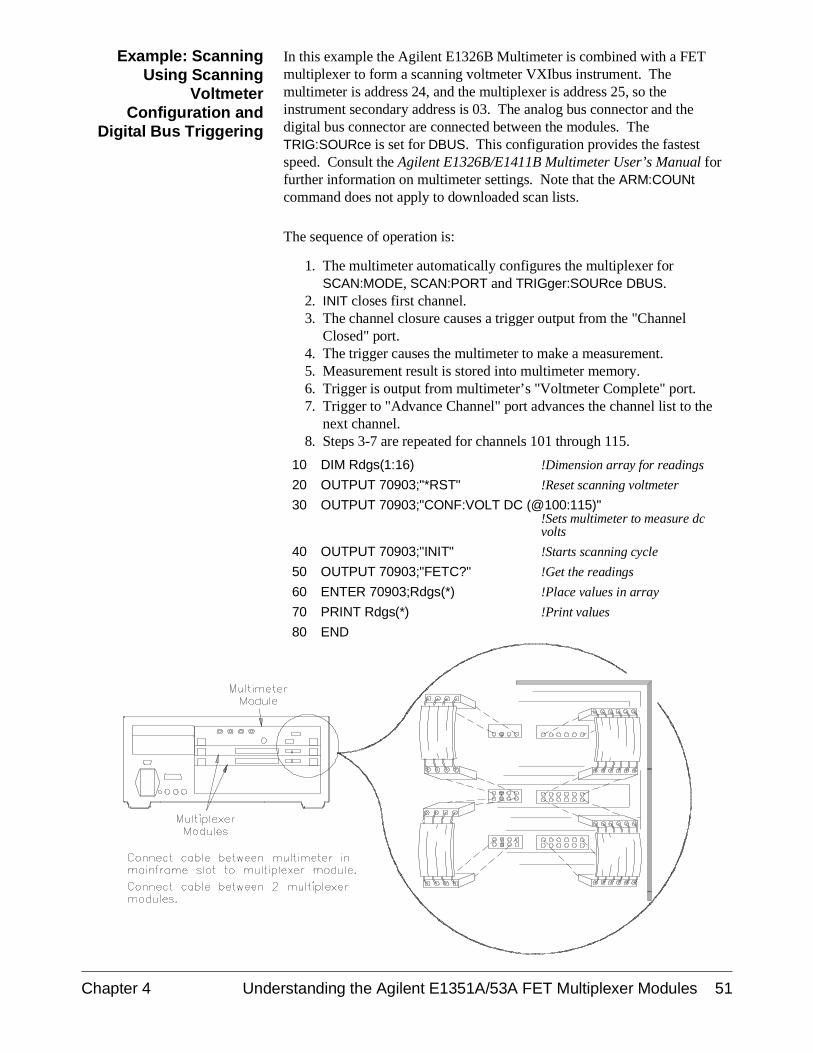
Example: ScanningUsing Scanning
VoltmeterConfiguration and
Digital Bus Triggering
In this example the Agilent E1326B Multimeter is combined with a FETmultiplexer to form a scanning voltmeter VXIbus instrument. Themultimeter is address 24, and the multiplexer is address 25, so theinstrument secondary address is 03. The analog bus connector and thedigital bus connector are connected between the modules. TheTRIG:SOURce is set for DBUS. This configuration provides the fastestspeed. Consult the Agilent E1326B/E1411B Multimeter User’s Manual forfurther information on multimeter settings. Note that the ARM:COUNtcommand does not apply to downloaded scan lists.
The sequence of operation is:
1. The multimeter automatically configures the multiplexer forSCAN:MODE, SCAN:PORT and TRIGger:SOURce DBUS.
2. INIT closes first channel.3. The channel closure causes a trigger output from the "Channel
Closed" port.4. The trigger causes the multimeter to make a measurement.5. Measurement result is stored into multimeter memory.6. Trigger is output from multimeter’s "Voltmeter Complete" port.7. Trigger to "Advance Channel" port advances the channel list to the
next channel.8. Steps 3-7 are repeated for channels 101 through 115.
10 DIM Rdgs(1:16) !Dimension array for readings
20 OUTPUT 70903;"*RST" !Reset scanning voltmeter
30 OUTPUT 70903;"CONF:VOLT DC (@100:115)"!Sets multimeter to measure dcvolts
40 OUTPUT 70903;"INIT" !Starts scanning cycle
50 OUTPUT 70903;"FETC?" !Get the readings
60 ENTER 70903;Rdgs(*) !Place values in array
70 PRINT Rdgs(*) !Print values
80 END
Chapter 4 Understanding the Agilent E1351A/53A FET Multiplexer Modules 51
Using the Scan Complete Bit
You can use the Scan Complete Bit (bit 8) in the SCPI Operation StatusRegister to determine when a scanning cycle completes (no other bits in theregister apply to the switchbox). Bit 8 has a decimal value of 256 and youcan read it directly with the STAT:OPER? command (refer to theSTATus:OPERation[:EVENt]? command in Chapter 5 for an example).Note that this is not the same register as the multiplexer Status/ControlRegister.
When enabled by the STAT:OPER:ENAB 256 command, the Scan CompleteBit will be reported as bit 7 of the Status Register. Use the GPIB Serial Pollor the IEEE 488.2 Common Command *STB? to read the Status Register.When bit 7 of the status Register is enabled by the *SRE 128 CommonCommand to assert an GPIB Service Request (SRQ), you can interrupt thecontroller when the Scan Complete Bit is set, after a scanning cyclecompletes. This allows the controller to do other operations while thescanning cycle is in progress.
The following example monitors bit 7 in the Status Register to determinewhen the scanning cycle completes. The computer used in the example isan HP Series 200/300 used with BASIC as the program language. Thecomputer interfaces with the mainframe over GPIB. The GPIB select codeis 7, the GPIB primary address is 09, and the GPIB secondary address is 14.
Example: ScanComplete Monitor
10 OUTPUT 70914;"*CLS" !Clear all switchbox statusstructure
20 OUTPUT 70914;"STAT:OPER:ENAB 256"!Enable Scan Complete Bit to setbit 7 in Status Register
30 OUTPUT 70914;"*SRE 128" !Enable bit 7 of Status Register toassert SRQ
40 OUTPUT 70914;"TRIG:SOUR EXT" !Set to external trigger mode
50 OUTPUT 70914;"SCAN (@100:115)" !Select channels to be scanned
60 OUTPUT 70914;"INIT" !Start scanning cycle
70 WHILE NOT BIT (SPOLL(70914),7) !Waiting for scan complete
80 PRINT "DO OTHER OPERATION HERE"!Enter program lines for computerto do other operations
90 END WHILE
100 PRINT "INTERRUPT GENERATED" !Program goes to this line afterinterrupt is generated by acompleted scanning cycle
110 END
52 Understanding the Agilent E1351A/53A FET Multiplexer Modules Chapter 4
Chapter 5Agilent E1351A/53A 16-Channel FET
Multiplexer Command Reference
Using This Chapter
This chapter describes Standard Commands for Programmable Instruments(SCPI) commands and summarizes IEEE 488.2 Common (*) Commandsapplicable to the 16-Channel FET and 16-Channel Thermocouple FETMultiplexer Modules. This chapter contains the following sections:
• Command Types . . . . . . . . . . . . . . . . . . . . . . . . . . . . . . . . . . Page 53• SCPI Command Reference . . . . . . . . . . . . . . . . . . . . . . . . . . Page 55• IEEE 488.2 Common Commands . . . . . . . . . . . . . . . . . . . . . Page 76• Command Quick Reference. . . . . . . . . . . . . . . . . . . . . . . . . . Page 77
Command Types
Commands are separated into two types: IEEE 488.2 Common Commandsand SCPI Commands.
CommonCommand Format
The IEEE 488.2 standard defines the Common Commands that performfunctions like reset, self-test, status byte query, etc. Common Commandsare three or four characters in length, always begin with the asteriskcharacter (*), and may include one or more parameters. The commandkeyword is separated from the first parameter by a space character. Someexamples of Common Commands are shown below:
*RST *ESR 32 *STB?
SCPI CommandFormat
The SCPI commands perform functions like closing switches, makingmeasurements, querying instrument states or retrieving data. A subsystemcommand structure is a hierarchical structure that usually consists of atop-level (or root) command, one or more lower level commands, and theirparameters. The following example shows part of a typical subsystem:
[ROUTe:]CLOSe <channel_list>SCAN <channel_list>
:MODE VOLT
[ROUTe:] is the root command, CLOSe and SCAN are second-levelcommands with <channel_list> as a parameter, and MODE is a third-levelcommand with the parameter VOLT.
Chapter 5 Agilent E1351A/53A 16-Channel FET Multiplexer Command Reference 53
Command Separator A colon (:) always separates one command from the next lower levelcommand as shown below:
ROUTe:SCAN:MODE VOLT
Colons separate the root command from the second-level command(ROUTe:SCAN) and the second-level from the third-level (SCAN:MODEVOLT). The parameters of a command are separated from the command bya blank space.
AbbreviatedCommands
The command syntax shows most commands as a mixture of upper andlower case letters. The upper case letters indicate the abbreviated spellingfor the command. For shorter program lines, send the abbreviated form.For better program readability, you may send the entire command. Theinstrument will accept either the abbreviated form or the entire command.
For example, if the command syntax shows MEASure, then MEAS andMEASURE are both acceptable forms. Other forms of MEASure, such asMEASU or MEASUR will generate an error. You may use upper or lowercase letters. Therefore, MEASURE, measure, and MeAsUrE are allacceptable.
Command keywords can be entered in their full form, as shown above, orcan be entered in their short form. In this manual, the entry required inshort form commands is always capitalized. The short form is generallyused for examples in this manual.
Implied Commands Implied commands are those which appear in square brackets ([ ]) in thecommand syntax. (Note that the brackets are not part of the command andare not sent to the instrument.) Suppose you send a second level commandbut do not send the preceding implied command. In this case, theinstrument assumes you intend to use the implied command and it respondsas if you had sent it. Examine this excerpt from the [ROUTe:] subsystemshown below:
[ROUTe:]SCAN <channel_list>
:MODE <mode>:MODE? :PORT <port>
Both the root command [ROUTe:] is an implied command. To set theinstrument’s scanning list, you can send either of the following commandstatements:
ROUTe:SCAN (@100:115) or SCAN (@100:115)
Note You must include a space between the keywords and any parameters.
54 Agilent E1351A/53A 16-Channel FET Multiplexer Command Reference Chapter 5
Parameters Parameter Types. The following table contains explanations and examplesof parameter types you might see later in this chapter.
Parameter Type Explanations and Examples
Numeric Accepts all commonly used decimal representations ofnumbers including optional signs, decimal points, andscientific notation.
123, 123E2, -123, -1.23E2, .123, 1.23E-2, 1.23000E-01.Special cases include MIN, MAX, and DEF. MIN selectsminimum value available, MAX selects maximum valueavailable, and DEF selects default or reset value.
Boolean Represents a single binary condition that is either true or false.
1 or ON; 0 or OFF.
Discrete Selects from a finite number of values. These parametersuse mnemonics to represent each valid setting.
An example is the TRIGger:SOURce <source> commandwhere source can be BUS, DBUS, EXT, HOLD, or IMM.
Optional Parameters. Parameters shown within square brackets ([ ]) areoptional parameters. (Note that the brackets are not part of the commandand are not sent to the instrument.) If you do not specify a value for anoptional parameter, the instrument chooses a default value. For example,consider the ARM:COUNt? [<MIN | MAX>] command. If you send thecommand without specifying a parameter, the present ARM:COUNt value isreturned. If you send the MIN parameter, the command returns theminimum count available. If you send the MAX parameter, the commandreturns the maximum count available. Be sure to place a space between thecommand and the parameter.
Linking Commands Linking IEEE 488.2 Common Commands with SCPI Commands. Use a semicolon between the commands. For example:
*RST;OUTP ON or TRIG:SOUR BUS;*TRG
Linking Multiple SCPI Commands. Use both a semicolon and a colonbetween the commands. For example:
ARM:COUN 1;:TRIG:SOUR EXT
SCPI Command Reference
This section describes the Standard Commands for ProgrammableInstruments (SCPI) commands for the multiplexer modules. Commands arelisted alphabetically by subsystem and also within each subsystem.
Chapter 5 Agilent E1351A/53A 16-Channel FET Multiplexer Command Reference 55
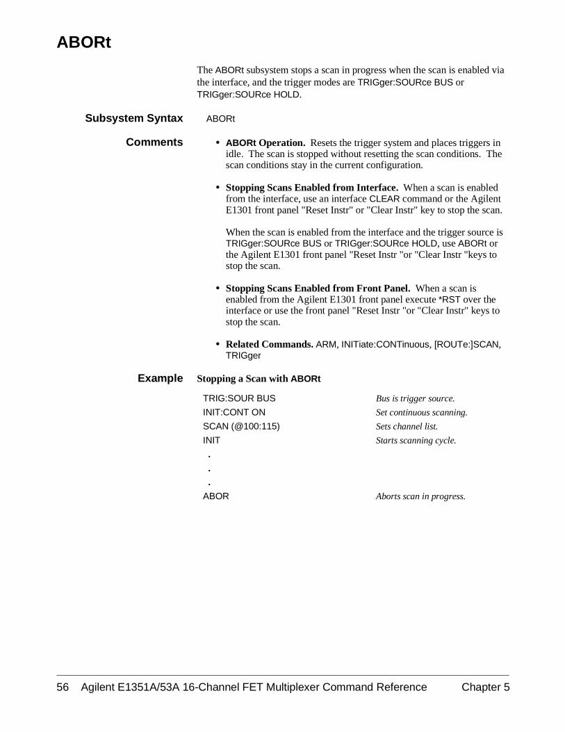
ABORt
The ABORt subsystem stops a scan in progress when the scan is enabled viathe interface, and the trigger modes are TRIGger:SOURce BUS orTRIGger:SOURce HOLD.
Subsystem Syntax ABORt
Comments • ABORt Operation. Resets the trigger system and places triggers inidle. The scan is stopped without resetting the scan conditions. Thescan conditions stay in the current configuration.
• Stopping Scans Enabled from Interface. When a scan is enabledfrom the interface, use an interface CLEAR command or the AgilentE1301 front panel "Reset Instr" or "Clear Instr" key to stop the scan.
When the scan is enabled from the interface and the trigger source isTRIGger:SOURce BUS or TRIGger:SOURce HOLD, use ABORt orthe Agilent E1301 front panel "Reset Instr "or "Clear Instr "keys tostop the scan.
• Stopping Scans Enabled from Front Panel. When a scan isenabled from the Agilent E1301 front panel execute *RST over theinterface or use the front panel "Reset Instr "or "Clear Instr" keys tostop the scan.
• Related Commands. ARM, INITiate:CONTinuous, [ROUTe:]SCAN,TRIGger
Example Stopping a Scan with ABORt
TRIG:SOUR BUS Bus is trigger source.
INIT:CONT ON Set continuous scanning.
SCAN (@100:115) Sets channel list.
INIT Starts scanning cycle.
.
.
.
ABOR Aborts scan in progress.
56 Agilent E1351A/53A 16-Channel FET Multiplexer Command Reference Chapter 5
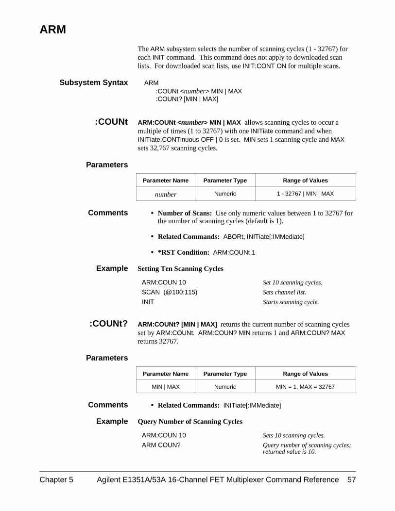
ARM
The ARM subsystem selects the number of scanning cycles (1 - 32767) foreach INIT command. This command does not apply to downloaded scanlists. For downloaded scan lists, use INIT:CONT ON for multiple scans.
Subsystem Syntax ARM:COUNt <number> MIN | MAX:COUNt? [MIN | MAX]
:COUNt ARM:COUNt <number> MIN | MAX allows scanning cycles to occur amultiple of times (1 to 32767) with one INITiate command and whenINITiate:CONTinuous OFF | 0 is set. MIN sets 1 scanning cycle and MAXsets 32,767 scanning cycles.
Parameters
Parameter Name Parameter Type Range of Values
number Numeric 1 - 32767 | MIN | MAX
Comments • Number of Scans: Use only numeric values between 1 to 32767 forthe number of scanning cycles (default is 1).
• Related Commands: ABORt, INITiate[:IMMediate]
• *RST Condition: ARM:COUNt 1
Example Setting Ten Scanning Cycles
ARM:COUN 10 Set 10 scanning cycles.
SCAN (@100:115) Sets channel list.
INIT Starts scanning cycle.
:COUNt? ARM:COUNt? [MIN | MAX] returns the current number of scanning cyclesset by ARM:COUNt. ARM:COUN? MIN returns 1 and ARM:COUN? MAXreturns 32767.
Parameters
Parameter Name Parameter Type Range of Values
MIN | MAX Numeric MIN = 1, MAX = 32767
Comments • Related Commands: INITiate[:IMMediate]
Example Query Number of Scanning Cycles
ARM:COUN 10 Sets 10 scanning cycles.
ARM COUN? Query number of scanning cycles;returned value is 10.
Chapter 5 Agilent E1351A/53A 16-Channel FET Multiplexer Command Reference 57
DISPlay
The DISPlay subsystem monitors the channel state of a selected module (orcard). This command can only be used when the FET multiplexer moduleis used in a switchbox configuration. It operates with mainframes that havea display, such as the Agilent 75000 Series B Mainframe (Agilent ModelNumber E1301). It also operates with terminals connected to the serialinterface port.
Subsystem Syntax DISPlay:MONitor :CARD <number | AUTO>
[:STATe] <mode>
:MONitor:CARD DISPlay:MONitor:CARD <number | AUTO> selects the module in aswitchbox to be monitored.
Parameters
Parameter Name Parameter Type Range of Values
number | AUTO Numeric 1 - 99
Comments • Selecting a Specific Module to be Monitored: Send the cardnumber in a switchbox with the DISPlay:MONitor:CARD command.
• Selecting the Present Module to be Monitored: Use theDISPlay:MONitor:CARD AUTO command to select the last moduleaddressed by a switching command (e.g., [ROUTe:]CLOSe).
• *RST Condition: DISPlay:MONitor:CARD AUTO
Example Select Module #2 in a Switchbox for Monitoring
DISP:MON:CARD 2 Selects module #2 in a switchbox.
58 Agilent E1351A/53A 16-Channel FET Multiplexer Command Reference Chapter 5
:MONitor[:STATe] DISPlay:MONitor[:STATe] <mode> turns the monitor mode on or off.
Parameters
Parameter Name Parameter Type Range of Values
mode Boolean 0 | 1 | ON | OFF
Comments • Monitoring Switchbox Channels: DISPlay:MONitor[:STATe] ONor DISPlay:MONitor[:STATe] 1 turns the monitor mode on to showthe channel state of the selected module. DISPlay:MONitor[:STATe]OFF or DISPlay:MONitor[:STATe] 0 turns the monitor mode off.
• Selecting the Module to be Monitored: Use the DISPlayMONitor:CARD <number> | AUTO command to select the module.
• Monitor Mode on an Agilent 1301 Mainframe Display: Thefollowing three examples show the types of display you will get:
Chan: _ No channels closed on this card.
Chan: 12 Channel 12 closed.
Chan: 9,1 4-wire ohms set-up with voltage onchannel 9.
• *RST Condition: DISPlay:MONitor[:STATe] OFF | 0
Example Enabling the Monitor Mode
DISP:MON:CARD 2 Selects module #2 in a switchbox.
DISP:MON 1 Turns the monitor mode on.
Chapter 5 Agilent E1351A/53A 16-Channel FET Multiplexer Command Reference 59
INITiate
The INITiate subsystem selects continuous scanning cycles and starts thescanning cycle.
Subsystem Syntax INITiate:CONTinuous <mode>:CONTinuous?[:IMMediate]
:CONTinuous INITiate:CONTinuous <mode> enables or disables continuous scanningcycles for the switchbox or scanning voltmeter.
Parameters
Parameter Name Parameter Type Range of Values
mode Boolean 0 | 1 | ON | OFF
Comments • Continuous Scanning Operation: Continuous scanning is enabledwith the INITiate:CONTinuous ON or INITiate:CONTinuous 1command. Sending the INITiate[:IMMediate] command closes thefirst channel in the channel list. Each trigger from a trigger sourcespecified by the TRIGger:SOURce command advances the scanthrough the channel list. A trigger at the end of the channel listcloses the first channel in the channel list and the scan cycle repeats.Continuous scanning can be stopped by the ABORt command fornon-downloaded scans, and by a system reset or a power off fordownloaded scan lists.
• Scanning a Set Number of Cycles: The INITiate:CONTinuous OFFor INITiate:CONTinuous 0 command goes through the scan list thenumber of times specified by the ARM:COUNt command. Sendingthe INITiate[:IMMediate] command closes the first channel in thechannel list. Each trigger from a trigger source selected by theTRIGger:SOURce command advances the scan through the channellist. A trigger at the end of the channel list opens the last channel inthe channel list, and if the number of cycles has not reached theARM:COUNt parameter, returns to the beginning of the scan list andcloses the first channel. When the number of cycles equals theARM:COUNt parameter, the scanning cycle stops. Note thatARM:COUNt does not apply to downloaded scan lists.
• Stopping Continuous Scans: Continuous scanning can be stoppedby the ABORt command for non-downloaded scans, and by a systemreset or a power off for downloaded scan lists.
• Related Commands: ABORt, ARM:COUNt, *RST, TRIGger,TRIGger:SOURce
• *RST Condition: INITiate:CONTinuous OFF
60 Agilent E1351A/53A 16-Channel FET Multiplexer Command Reference Chapter 5
Example Enabling Continuous Scans
INIT:CONT ON Enables continuous scanning.
SCAN (@100:115) Sets channel list.
INIT Starts scanning cycle.
:CONTinuous? INITiate:CONTinuous? queries the scanning state. With continuousscanning enabled, the command returns 1 (ON). With continuous scanningdisabled, the command returns 0 (OFF).
Example Query Continuous Scanning State
INIT:CONT ON Enables continuous scanning.
INIT:CONT? Query continuous scanning state.
[:IMMediate] INITiate[:IMMediate] starts the scanning cycle and closes the first channelin the channel list. Successive triggers from the source specified by theTRIGger:SOURce command advances the scan through the channel list.
Comments • Starting the Scanning Cycle: The INITiate[:IMMediate] commandstarts scanning by closing the first channel in the channel list. Eachtrigger received advances the scan to the next channel in the channellist. An invalid channel list generates an error (see the[ROUTe:]SCAN command).
• Stopping Scanning Cycles: See the ABORt command.
Example Enabling a Single Scan
SCAN (@100:115) Sets channel list.
INIT Starts scanning cycle.
Chapter 5 Agilent E1351A/53A 16-Channel FET Multiplexer Command Reference 61
OUTPut
The OUTPut subsystem enables or disables the "Trig Out" port of theAgilent E1300/E1301 Mainframe.
Subsystem Syntax OUTPut [:STATe] <state>[:STATe]?
[:STATe] OUTPut[:STATe] <state> enables/disables the "Trig Out" port on the rearpanel of the Agilent E1300/E1301 Mainframe. OUTPut[:STATe] ON | 1enables the port and OUTPut[:STATe] OFF | 0 disables the port.
Parameters
Parameter Name Parameter Type Range of Values
state Boolean 0 | 1 | ON | OFF
Comments • Downloaded Scans: The OUTPut subsystem does not work withdownloaded scan lists. The scan list is downloaded automatically ifyou use TRIG:SOUR DBUS or TRIG:SOUR IMM (FET multiplexersonly). OUTPut works with all other scanning methods.
• Enabling "Trig Out" Port: When enabled, the "Trig Out" port ispulsed each time a channel is closed during scanning. Whendisabled, the "Trig Out" port is not pulsed.
• Output Pulse: The pulse is a +5 V negative-going pulse.
• "Trig Out" Port Reserved by Switchboxes: The "Trig Out"resource is a system resource, and can only be reserved by oneinstrument at a time.
• Related Commands: [ROUTe:]SCAN, TRIGger:SOURce
• *RST Condition: OUTPut[:STATe] OFF (port disabled)
Example Enabling "Trig Out" Port
OUTP ON Enables "Trig Out" port for pulseoutput.
[:STATe]? OUTPut[:STATe]? queries the present state of the "Trig Out" port. Thecommand returns 1 if the port is enabled, or 0 if disabled.
Example Query "Trig Out" Port State
OUTP ON Enables "Trig Out" port for pulseoutput.
OUTP:STAT? Query port enable state.
62 Agilent E1351A/53A 16-Channel FET Multiplexer Command Reference Chapter 5
[ROUTe:]
The [ROUTe:] subsystem controls switching and scanning operations for themultiplexer modules in a switchbox.
Subsystem Syntax [ROUTe:]CLOSe <channel_list>CLOSe? <channel_list>OPEN <channel_list>OPEN? <channel list>SCAN <channel_list>
:MODE <mode>:MODE?:PORT <port>:PORT?
SETTling [:TIME] <time>, <channel_list>
[:TIME]? [MIN | MAX] <channel_list>
CLOSe [ROUTe:]CLOSe <channel_list> closes multiplexer channels specified in thechannel list. The channel_list for CLOSe is in the form (@ccnn), or in specialcircumstances, (@ccnn,ccnn), where cc = card number (00-99) and nn = channelnumber (00-15). Before using the CLOSe command, you must specify theSCAN:MODE and SCAN:PORT, as these commands determine what switcheswill be closed for a given channel. You can only have one closed channel on acard at a time. If you want to close a channel on two different cards in the sameVXIbus instrument (for example, 102,208) you can use (@ccnn,ccnn).
Parameters
Parameter Name Parameter Type Range of Values
channel_list Numeric cc00 - cc15
Comments • Specify SCAN:MODE and SCAN:PORT: Before using the CLOSecommand, specify the SCAN:MODE and SCAN:PORT.
• Closing Channels: To close: – use [ROUTe:]CLOSe (@ccnn) for a single channel;– use [ROUTe:]CLOSe (@ccnn,ccnn) for single channels on
different cards;– use [ROUTe:]CLOSe (@ccnn,ccnn) for multiple channels;– use [ROUTe:]CLOSe (@ccnn:ccnn) for sequential channels;– use [ROUTe:]CLOSe (@ccnn:ccnn,ccnn:ccnn) for a group of
sequential channels;– or any combination.
Closure order for multiple channels with a single command isnot guaranteed.
• Related Commands: [ROUTe:]OPEN, [ROUTe:]CLOSe?,[ROUTe:]SCAN:MODE, [ROUTe:]SCAN:PORT
Chapter 5 Agilent E1351A/53A 16-Channel FET Multiplexer Command Reference 63
• *RST Condition: All multiplexer channels are open.
Example Closing Multiplexer Channels
This example closes channel 00 of a multiplexer module card number 1 andchannel 15 of multiplexer module card number 2 in a single switchbox.
SCAN:MODE VOLT
SCAN:PORT ABUS
CLOS (@100,215) 100 closes channel 00 of card #1;215 closes channel 15 of card #2.
CLOSe? [ROUTe:]CLOSe? <channel_list> returns the current state of thechannel(s) queried. The channel list is in the form (@ccnn). The commandreturns 1 if channels are closed and returns 0 if the channels are open.
Comments • Query is Software Readback: The [ROUTe:]CLOSe? commandreturns the current software state of the channel specified. It doesnot account for relay hardware failures.
Example Query Multiplexer Channel Closure
CLOS (@100,215) 100 closes channel 00 of card #1;215 closes channel 15 of card #2.
CLOS? (@215) Query channel 215.
OPEN [ROUTe:]OPEN <channel_list> opens the multiplexer channels specifiedin the channel_list. The channel_list is in the form (@ccnn), (@ccnn,ccnn),(@ccnn:ccnn) or (@ccnn:ccnn,ccnn:ccnn) where cc = card number (00-99)and nn = channel number (00-15).
Parameters
Parameter Name Parameter Type Range of Values
channel_list Numeric cc00 - cc15
Comments • Opening Channels: To open:
– use [ROUTe:]OPEN (@ccnn) for a single channel;– use [ROUTe:]OPEN (@ccnn,ccnn) for multiple channels;– use [ROUTe:]OPEN (@ccnn:ccnn) for sequential channels;– use [ROUTe:]OPEN (@ccnn:ccnn,ccnn:ccnn) for a group of
sequential channels;– or any combination.
Opening order for multiple channels with a single command is notguaranteed.
• Open Channels: Opening an already open channel has no effect.
• Related Commands: [ROUTe:]CLOSe, [ROUTe:]OPEN?
64 Agilent E1351A/53A 16-Channel FET Multiplexer Command Reference Chapter 5
• *RST Condition: All multiplexer channels are open.
Example Opening Multiplexer Channels
This example opens channel 00 of a multiplexer module card number 1 andchannel 15 of multiplexer module card number 2 in a single switchbox.
OPEN (@100,215) 100 opens channel 00 of card #1;215 opens channel 15 of card #2.
OPEN? [ROUTe:]OPEN? <channel_list> returns the current state of the channel(s)queried. The channel list is in the form (@ccnn). The command returns 1if the channel is open or returns 0 if the channel is closed.
Comments • Query is Software Readback: The [ROUTe:]OPEN? commandreturns the current software state of the channel(s) specified. It doesnot account for relay hardware failures.
Example Query Multiplexer Channel Open State
OPEN (@100,215) 100 opens channel 00 of card #1;215 opens channel 15 of card #2.
OPEN? (@215) Query state of channel 215.
SCAN [ROUTe:]SCAN <channel_list> defines the channels to be scanned. Thechannel_list has the form (@ccnn), (@ccnn,ccnn), (@ccnn:ccnn) or(@ccnn:ccnn,ccnn:ccnn) where cc = card number (00-99) and nn = channelnumber (00-15).
Parameters
Parameter Name Parameter Type Range of Values
channel_list Numeric cc00 - cc15
Comments • Channel List: Valid channel lists are:
– a single channel, use (@ccnn);– for multiple channels, use (@ccnn,ccnn);– sequential channels, use (@ccnn:ccnn);– a group of sequential channels, use (@ccnn:ccnn,ccnn:ccnn);– or any combination.
• Defining the Channel List. When executing [ROUTe:]SCAN, thechannel list is checked for valid card and channel numbers. An erroris generated for an invalid channel list.
• Downloading a Scanning List: The channel_list is automaticallydownloaded into RAM on the FET multiplexer modules forTRIG:SOUR DBUS and TRIG:SOUR IMM trigger modes. Thecomplete list is downloaded onto each module in an instrument. Thechannels are advanced with no direct intervention by the mainframeCPU during the scan. If an instrument contains mixed modules (FETand Relay Multiplexers), the scan list will not be downloaded.
Chapter 5 Agilent E1351A/53A 16-Channel FET Multiplexer Command Reference 65
• Scanning Operation: With a valid channel list,INITiate[:IMMediate] starts the scanning cycle and closes the firstchannel in the channel list. Successive triggers from the sourcespecified by TRIGger:SOURce advances the scan through thechannel list.
• Stopping Scan: See the ABORt command.
• Related Commands: TRIGger, TRIGger:SOURce
• *RST Condition: All multiplexers channels are open.
Example Scanning Using External Instruments
The following example shows how to scan channels using the AgilentE1300B/E1301B Mainframe via GPIB and an Agilent 3457A DigitalMultimeter. This example uses the mainframe’s "Trig Out" port tosynchronize the multiplexer module in a switchbox to the multimeter. Thetrigger pulse from the port triggers the multimeter for a measurement. SeeChapters 2 and 3 for typical user connections to the multiplexer.
The computer used in the example is an HP Series 200/300 with BASIC asthe program language. The computer interfaces with the mainframe overGPIB. Assumed is an GPIB select code of 7, an GPIB primary address of09 and 22 for the Agilent E1300B/E1301B Mainframe and Agilent 3457AMultimeter, respectively, and an GPIB secondary address of 14 for theswitchbox.
10 OUTPUT 722;"TRIG EXT;DCV" !Sets multimeter to external triggerand to measure dc volts
20 OUTPUT 70914;"OUTP ON" !Enables "Trig Out" port
30 OUTPUT 70914;"TRIG:SOUR BUS" !Sets switchbox to receive bustriggers
40 OUTPUT 70914;"SCAN:MODE VOLT"!Sets switchbox to measurevoltage during scanning
50 OUTPUT 70914; "SCAN:PORT ABUS"!Sets switchbox to close theappropriate tree switches duringscanning
60 OUTPUT 70914;"SCAN (@100:115)"!Selects the channel list
70 OUTPUT 70914;"INIT" !Starts scanning cycle
80 FOR I = 1 TO 16 !Start count loop
90 ENTER 722;A !Enter reading into variable A
100 PRINT A !Print reading in variable A
110 TRIGGER 70914 !Trigger the switchbox to advancethe channel list
120 NEXT I !Increment count
130 END
66 Agilent E1351A/53A 16-Channel FET Multiplexer Command Reference Chapter 5
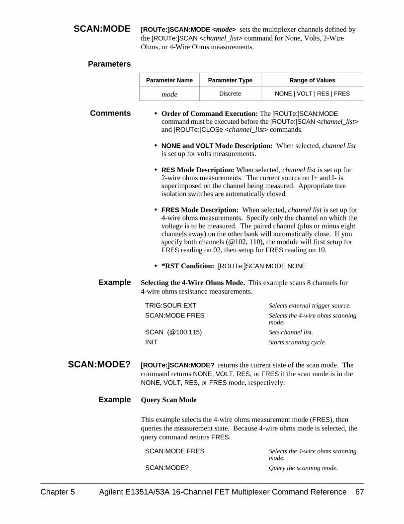
SCAN:MODE [ROUTe:]SCAN:MODE <mode> sets the multiplexer channels defined bythe [ROUTe:]SCAN <channel_list> command for None, Volts, 2-WireOhms, or 4-Wire Ohms measurements.
Parameters
Parameter Name Parameter Type Range of Values
mode Discrete NONE | VOLT | RES | FRES
Comments • Order of Command Execution: The [ROUTe:]SCAN:MODE command must be executed before the [ROUTe:]SCAN <channel_list>and [ROUTe:]CLOSe <channel_list> commands.
• NONE and VOLT Mode Description: When selected, channel listis set up for volts measurements.
• RES Mode Description: When selected, channel list is set up for2-wire ohms measurements. The current source on I+ and I- issuperimposed on the channel being measured. Appropriate treeisolation switches are automatically closed.
• FRES Mode Description: When selected, channel list is set up for4-wire ohms measurements. Specify only the channel on which thevoltage is to be measured. The paired channel (plus or minus eightchannels away) on the other bank will automatically close. If youspecify both channels (@102, 110), the module will first setup forFRES reading on 02, then setup for FRES reading on 10.
• *RST Condition: [ROUTe:]SCAN:MODE NONE
Example Selecting the 4-Wire Ohms Mode. This example scans 8 channels for4-wire ohms resistance measurements.
TRIG:SOUR EXT Selects external trigger source.
SCAN:MODE FRES Selects the 4-wire ohms scanningmode.
SCAN (@100:115) Sets channel list.
INIT Starts scanning cycle.
SCAN:MODE? [ROUTe:]SCAN:MODE? returns the current state of the scan mode. Thecommand returns NONE, VOLT, RES, or FRES if the scan mode is in theNONE, VOLT, RES, or FRES mode, respectively.
Example Query Scan Mode
This example selects the 4-wire ohms measurement mode (FRES), thenqueries the measurement state. Because 4-wire ohms mode is selected, thequery command returns FRES.
SCAN:MODE FRES Selects the 4-wire ohms scanningmode.
SCAN:MODE? Query the scanning mode.
Chapter 5 Agilent E1351A/53A 16-Channel FET Multiplexer Command Reference 67
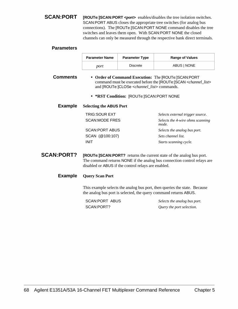
SCAN:PORT [ROUTe:]SCAN:PORT <port> enables/disables the tree isolation switches.SCAN:PORT ABUS closes the appropriate tree switches (for analog busconnections). The [ROUTe:]SCAN:PORT NONE command disables the treeswitches and leaves them open. With SCAN:PORT NONE the closedchannels can only be measured through the respective bank direct terminals.
Parameters
Parameter Name Parameter Type Range of Values
port Discrete ABUS | NONE
Comments • Order of Command Execution: The [ROUTe:]SCAN:PORTcommand must be executed before the [ROUTe:]SCAN <channel_list>and [ROUTe:]CLOSe <channel_list> commands.
• *RST Condition: [ROUTe:]SCAN:PORT NONE
Example Selecting the ABUS Port
TRIG:SOUR EXT Selects external trigger source.
SCAN:MODE FRES Selects the 4-wire ohms scanningmode.
SCAN:PORT ABUS Selects the analog bus port.
SCAN (@100:107) Sets channel list.
INIT Starts scanning cycle.
SCAN:PORT? [ROUTe:]SCAN:PORT? returns the current state of the analog bus port.The command returns NONE if the analog bus connection control relays aredisabled or ABUS if the control relays are enabled.
Example Query Scan Port
This example selects the analog bus port, then queries the state. Becausethe analog bus port is selected, the query command returns ABUS.
SCAN:PORT ABUS Selects the analog bus port.
SCAN:PORT? Query the port selection.
68 Agilent E1351A/53A 16-Channel FET Multiplexer Command Reference Chapter 5
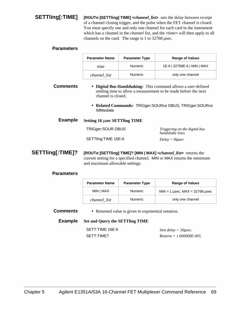
SETTling[:TIME] [ROUTe:]SETTling[:TIME] <channel_list> sets the delay between receiptof a channel closing trigger, and the pulse when the FET channel is closed.You must specify one and only one channel for each card in the instrumentwhich has a channel in the channel list, and the <time> will then apply to allchannels on the card. The range is 1 to 32768 µsec.
Parameters
Parameter Name Parameter Type Range of Values
time Numeric 1E-6 | 32768E-6 | MIN | MAX
channel_list Numeric only one channel
Comments • Digital Bus Handshaking: This command allows a user-definedsettling time to allow a measurement to be made before the nextchannel is closed.
• Related Commands: TRIGger:SOURce DBUS, TRIGger:SOURceIMMediate
Example Setting 16 µsec SETTling TIME
TRIGger:SOUR DBUS Triggering on the digital bushandshake lines
SETTling:TIME 16E-6 Delay = l6µsec
SETTling[:TIME]? [ROUTe:]SETTling[:TIME]? [MIN | MAX] <channel_list> returns thecurrent setting for a specified channel. MIN or MAX returns the minimumand maximum allowable settings.
Parameters
Parameter Name Parameter Type Range of Values
MIN | MAX Numeric MIN = 1 µsec, MAX = 32768 µsec
channel_list Numeric only one channel
Comments • Returned value is given in exponential notation.
Example Set and Query the SETTling TIME
SETT:TIME 16E-6 Sets delay = 16µsec.
SETT:TIME? Returns + 1.600000E-005.
Chapter 5 Agilent E1351A/53A 16-Channel FET Multiplexer Command Reference 69
STATus
The STATus subsystem reports the bit values of the Operation StatusRegister. This enables the Status Register to set a bit after a bit is set to 1 bythe Operation Status Register.
Subsystem Syntax STATus:OPERation
:ENABle <number>[:EVENt]?
:OPERation:ENABle STATus:OPERation:ENABle <number> enables the Operation StatusRegister to set a bit in the Status Register. For multiplexer modules, whenbit 8 in the Operation Status Register is set to 1, bit 7 in the Status Registeris set to 1.
Parameters
Parameter Name Parameter Type Range of Values
number Numeric 1 - 32768
Comments • Setting Bit 7 of the Status Register: STATus:OPERation:ENABle256 sets bit 7 of the Status Register to 1 after bit 8 of the OperationStatus Register is set to 1.
• Disabling STATus:OPERation: The STATus:PRESet commanddisables the STATus:OPERation:ENABle command.
• Related Commands: [ROUTe:]SCAN, *SRE, *STB?, *SPOLL,STATus:PRESet
Example Enable the Status Register Bit 7
STAT:OPER:ENAB 256 Enables bit 7 of the Status Register.
:OPERation[:EVENt]? STATus:OPERation[:EVENt]? returns the bit value of the OperationStatus Register (only bit 8 is used by the multiplexer modules).
Comments • Setting Bit 8 of the Operation Status Register: Bit 8 (ScanComplete) is set to 1 after a scanning cycle completes. Bit 8 returnsto 0 after sending the STATus:OPERation[:EVENt]? command. Forcorrect operation set to 0 by *CLS before scanning.
• Returned Data after sending the STATus:OPERation[:EVENt]?Command: The command returns +256 if bit 8 of the OperationStatus Register is set to 1. The command returns +0 if bit 8 of theOperation Status Register is set to 0.
• Related Commands: [ROUTe:]SCAN, *SRE, *STB?, *SPOLL
Example Reading the Operation Status Register after a Scanning Cycle
STAT:OPER? Reads the register value
70 Agilent E1351A/53A 16-Channel FET Multiplexer Command Reference Chapter 5
read and print the register value +256 shows bit 8 is set to 1; +0shows bit 8 is set to 0.
SYSTem
The SYSTem subsystem returns the error numbers and error messages inthe error queue of a switchbox, and returns the types and descriptions ofmodules (cards) in a switchbox.
Subsystem Syntax SYSTem:CDEScription? <number>:CPON <number | ALL>:CTYPe? <number>:ERRor?
:CDEScription? SYSTem:CDEScription? <number> returns the description of a selectedmodule (card) in a switchbox.
Parameters
Parameter Name Parameter Type Range of Values
number Numeric 1 - 99
Comments • 16-Channel FET Multiplexer Module Description: TheSYSTem:CDEScription? <number> command returns:
16 Channel FET Mux
• 16-Channel Thermocouple FET Multiplexer Module Description:The SYSTem:CDEScription? <number> command returns:
16 Channel FET Mux with T/C
Example Reading the Description of Card #1 Module
SYST:CDES? 1 Determine the description.
:CPON SYSTem:CPON <number | ALL> opens all channels of a selected module,or all modules (cards) in a switchbox.
Parameters
Parameter Name Parameter Type Range of Values
number Numeric 1 - 99 | ALL
Comments • Differences between *RST and CPON: SYSTem:CPON only opensall channels of a selected module or all modules in a switchbox.*RST opens all channels of all modules in a switchbox and also setsthe trigger modes to the power-on states.
Chapter 5 Agilent E1351A/53A 16-Channel FET Multiplexer Command Reference 71
Example Opening All Channels on Card #1
SYST:CPON 1 Opens all channels on card #1.
:CTYPe? SYSTem:CTYPe? <number> returns the module (card) type of a selectedmodule in a switchbox.
Parameters
Parameter Name Parameter Type Range of Values
number Numeric 1 - 99
Comments • 16-Channel FET Multiplexer Module Model Number: The SYSTem:CTYPe? <number> command returns:
HEWLETT-PACKARD,E1351A,0,A.03.00
• 16-Channel Thermocouple FET Multiplexer Module Model Number: The SYSTem:CTYPe? <number> command returns:
HEWLETT-PACKARD,E1353A,0,A.03.00
Note: The first number after the model number is the serial numberof the module (always 0); the module revision code follows theserial number (for example, A.03.00).
Example Reading the Model Number of a Card #1 Module
SYST:CTYP? 1 Determine the model number.
:ERRor? SYSTem:ERRor? returns the error numbers and corresponding errormessages in the error queue of a switchbox. See Appendix C for a listing ofthe switchbox error numbers and messages.
Comments • Error Numbers/Messages in the Error Queue: Errors generatedby a switchbox stores an error number and corresponding errormessage in the error queue. Each error message can be up to 255characters long.
• Clearing the Error Queue: An error number/message is removedfrom the queue each time the SYSTem:ERRor? command is sent.The errors are cleared first-in, first-out. When the queue is empty,each following SYSTem:ERRor? command returns 0, "No error".To clear all error numbers/messages in the queue, execute the *CLScommand.
• Maximum Error Numbers/Messages in the Error Queue: Thequeue holds a maximum of 30 error numbers/messages for eachswitchbox. If the queue overflows, the last error number/message inthe queue is replaced by -350, "Too many errors". The least recenterror numbers/messages remain in the queue and the most recent arediscarded.
72 Agilent E1351A/53A 16-Channel FET Multiplexer Command Reference Chapter 5
Example Reading the Error Queue
SYST:ERR? Query the error queue.
TRIGger
The TRIGger subsystem commands control the scan triggering operation ofthe multiplexer modules.
Subsystem Syntax TRIGger[:IMMediate]:SOURce BUS | DBUS | EXTernal | HOLD | IMMediate:SOURce?
[:IMMediate] TRIGger[:IMMediate] causes a trigger to occur when the defined triggersource is TRIGger:SOURce HOLD or TRIGger:SOURce BUS. Note thatTRIGger[:IMM] is not the same as TRIGger:SOURce IMM.
Comments • Executing the TRIGger[:IMMediate] Command: A channel listmust be defined with the [ROUTe:]SCAN <channel_list> commandand an INITiate[:IMMediate] command must be executed beforeTRIGger[:IMMediate] can trigger the switchbox.
• HOLD or BUS Source Remains: If selected, the TRIGger:SOURceHOLD or TRIGger:SOURce BUS commands remain in effect aftertriggering the switchbox with the TRIGger[:IMMediate] command.
• Related Commands: INITiate, [ROUTe:]SCAN
Example Advancing Scan using the TRIGger Command
TRIG:SOUR HOLD Sets trigger source to hold.
SCAN (@100:115) Sets channel list.
INIT Starts scanning cycle.
loop statement Start count loop.
TRIG Advances scan to next channel.
increment loop Increment count loop.
Chapter 5 Agilent E1351A/53A 16-Channel FET Multiplexer Command Reference 73
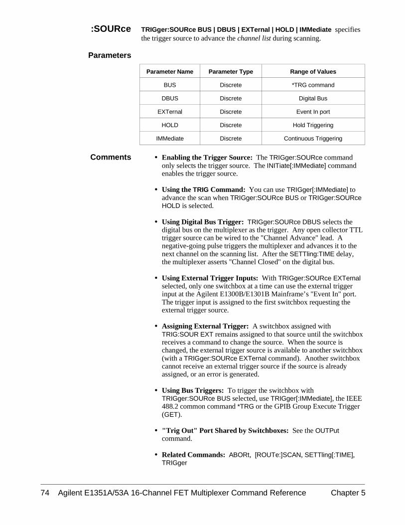
:SOURce TRIGger:SOURce BUS | DBUS | EXTernal | HOLD | IMMediate specifiesthe trigger source to advance the channel list during scanning.
Parameters
Parameter Name Parameter Type Range of Values
BUS Discrete *TRG command
DBUS Discrete Digital Bus
EXTernal Discrete Event In port
HOLD Discrete Hold Triggering
IMMediate Discrete Continuous Triggering
Comments • Enabling the Trigger Source: The TRIGger:SOURce commandonly selects the trigger source. The INITiate[:IMMediate] commandenables the trigger source.
• Using the TRIG Command: You can use TRIGger[:IMMediate] toadvance the scan when TRIGger:SOURce BUS or TRIGger:SOURceHOLD is selected.
• Using Digital Bus Trigger: TRIGger:SOURce DBUS selects thedigital bus on the multiplexer as the trigger. Any open collector TTLtrigger source can be wired to the "Channel Advance" lead. Anegative-going pulse triggers the multiplexer and advances it to thenext channel on the scanning list. After the SETTling:TIME delay,the multiplexer asserts "Channel Closed" on the digital bus.
• Using External Trigger Inputs: With TRIGger:SOURce EXTernalselected, only one switchbox at a time can use the external triggerinput at the Agilent E1300B/E1301B Mainframe’s "Event In" port.The trigger input is assigned to the first switchbox requesting theexternal trigger source.
• Assigning External Trigger: A switchbox assigned withTRIG:SOUR EXT remains assigned to that source until the switchboxreceives a command to change the source. When the source ischanged, the external trigger source is available to another switchbox(with a TRIGger:SOURce EXTernal command). Another switchboxcannot receive an external trigger source if the source is alreadyassigned, or an error is generated.
• Using Bus Triggers: To trigger the switchbox withTRIGger:SOURce BUS selected, use TRIGger[:IMMediate], the IEEE488.2 common command *TRG or the GPIB Group Execute Trigger(GET).
• "Trig Out" Port Shared by Switchboxes: See the OUTPutcommand.
• Related Commands: ABORt, [ROUTe:]SCAN, SETTling[:TIME],TRIGger
74 Agilent E1351A/53A 16-Channel FET Multiplexer Command Reference Chapter 5
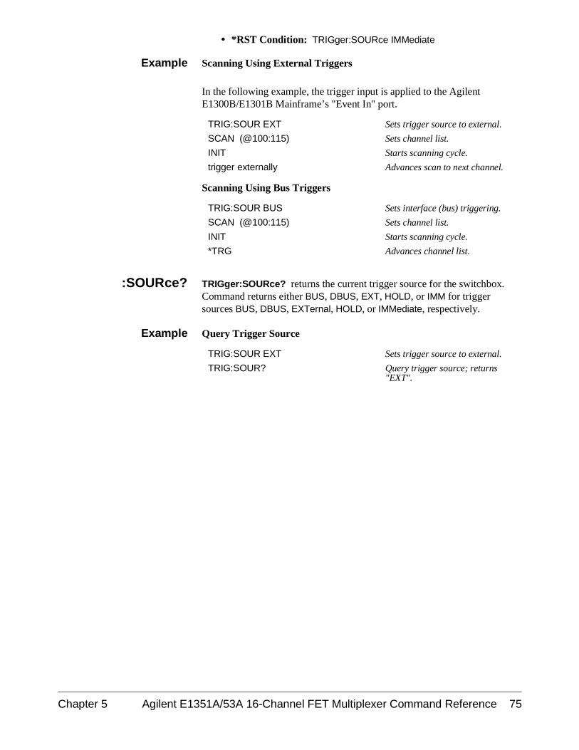
• *RST Condition: TRIGger:SOURce IMMediate
Example Scanning Using External Triggers
In the following example, the trigger input is applied to the AgilentE1300B/E1301B Mainframe’s "Event In" port.
TRIG:SOUR EXT Sets trigger source to external.
SCAN (@100:115) Sets channel list.
INIT Starts scanning cycle.
trigger externally Advances scan to next channel.
Scanning Using Bus Triggers
TRIG:SOUR BUS Sets interface (bus) triggering.
SCAN (@100:115) Sets channel list.
INIT Starts scanning cycle.
*TRG Advances channel list.
:SOURce? TRIGger:SOURce? returns the current trigger source for the switchbox.Command returns either BUS, DBUS, EXT, HOLD, or IMM for triggersources BUS, DBUS, EXTernal, HOLD, or IMMediate, respectively.
Example Query Trigger Source
TRIG:SOUR EXT Sets trigger source to external.
TRIG:SOUR? Query trigger source; returns"EXT".
Chapter 5 Agilent E1351A/53A 16-Channel FET Multiplexer Command Reference 75
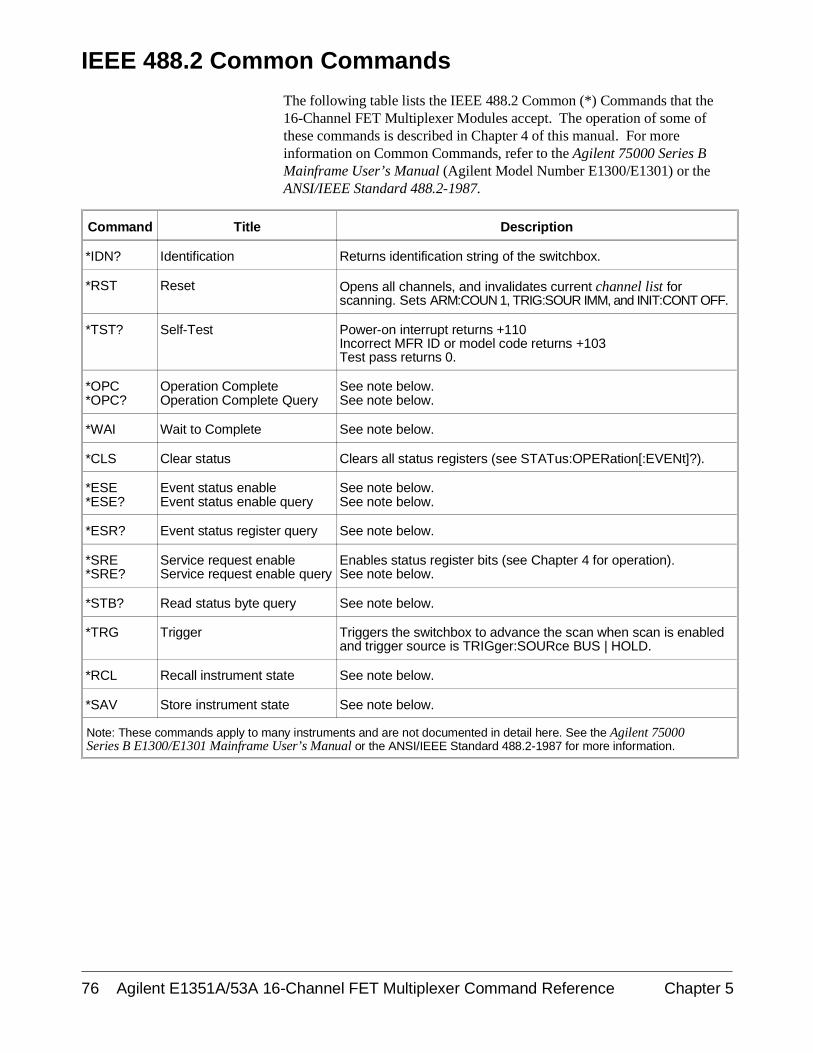
IEEE 488.2 Common Commands
The following table lists the IEEE 488.2 Common (*) Commands that the16-Channel FET Multiplexer Modules accept. The operation of some ofthese commands is described in Chapter 4 of this manual. For moreinformation on Common Commands, refer to the Agilent 75000 Series BMainframe User’s Manual (Agilent Model Number E1300/E1301) or theANSI/IEEE Standard 488.2-1987.
Command Title Description
*IDN? Identification Returns identification string of the switchbox.
*RST Reset Opens all channels, and invalidates current channel list forscanning. Sets ARM:COUN 1, TRIG:SOUR IMM, and INIT:CONT OFF.
*TST? Self-Test Power-on interrupt returns +110Incorrect MFR ID or model code returns +103Test pass returns 0.
*OPC*OPC?
Operation CompleteOperation Complete Query
See note below. See note below.
*WAI Wait to Complete See note below.
*CLS Clear status Clears all status registers (see STATus:OPERation[:EVENt]?).
*ESE*ESE?
Event status enableEvent status enable query
See note below.See note below.
*ESR? Event status register query See note below.
*SRE*SRE?
Service request enableService request enable query
Enables status register bits (see Chapter 4 for operation). See note below.
*STB? Read status byte query See note below.
*TRG Trigger Triggers the switchbox to advance the scan when scan is enabledand trigger source is TRIGger:SOURce BUS | HOLD.
*RCL Recall instrument state See note below.
*SAV Store instrument state See note below.
Note: These commands apply to many instruments and are not documented in detail here. See the Agilent 75000 Series B E1300/E1301 Mainframe User’s Manual or the ANSI/IEEE Standard 488.2-1987 for more information.
76 Agilent E1351A/53A 16-Channel FET Multiplexer Command Reference Chapter 5
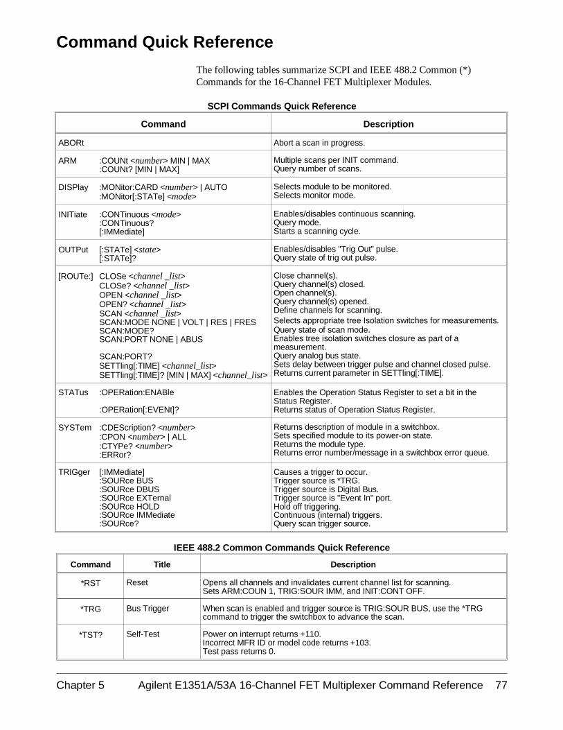
Command Quick Reference
The following tables summarize SCPI and IEEE 488.2 Common (*)Commands for the 16-Channel FET Multiplexer Modules.
SCPI Commands Quick Reference
Command Description
ABORt Abort a scan in progress.
ARM :COUNt <number> MIN | MAX:COUNt? [MIN | MAX]
Multiple scans per INIT command.Query number of scans.
DISPlay :MONitor:CARD <number> | AUTO:MONitor[:STATe] <mode>
Selects module to be monitored.Selects monitor mode.
INITiate :CONTinuous <mode> :CONTinuous?[:IMMediate]
Enables/disables continuous scanning.Query mode.Starts a scanning cycle.
OUTPut [:STATe] <state>[:STATe]?
Enables/disables "Trig Out" pulse.Query state of trig out pulse.
[ROUTe:] CLOSe <channel _list>CLOSe? <channel _list>OPEN <channel _list>OPEN? <channel _list>SCAN <channel _list>SCAN:MODE NONE | VOLT | RES | FRESSCAN:MODE?SCAN:PORT NONE | ABUS
SCAN:PORT?SETTling[:TIME] <channel_list>SETTling[:TIME]? [MIN | MAX] <channel_list>
Close channel(s).Query channel(s) closed.Open channel(s).Query channel(s) opened.Define channels for scanning.Selects appropriate tree Isolation switches for measurements.Query state of scan mode.Enables tree isolation switches closure as part of ameasurement.Query analog bus state.Sets delay between trigger pulse and channel closed pulse.Returns current parameter in SETTling[:TIME].
STATus :OPERation:ENABle
:OPERation[:EVENt]?
Enables the Operation Status Register to set a bit in theStatus Register.Returns status of Operation Status Register.
SYSTem :CDEScription? <number>:CPON <number> | ALL:CTYPe? <number>:ERRor?
Returns description of module in a switchbox.Sets specified module to its power-on state.Returns the module type.Returns error number/message in a switchbox error queue.
TRIGger [:IMMediate]:SOURce BUS:SOURce DBUS:SOURce EXTernal:SOURce HOLD:SOURce IMMediate:SOURce?
Causes a trigger to occur.Trigger source is *TRG.Trigger source is Digital Bus.Trigger source is "Event In" port.Hold off triggering.Continuous (internal) triggers.Query scan trigger source.
IEEE 488.2 Common Commands Quick Reference
Command Title Description
*RST Reset Opens all channels and invalidates current channel list for scanning. Sets ARM:COUN 1, TRIG:SOUR IMM, and INIT:CONT OFF.
*TRG Bus Trigger When scan is enabled and trigger source is TRIG:SOUR BUS, use the *TRGcommand to trigger the switchbox to advance the scan.
*TST? Self-Test Power on interrupt returns +110.Incorrect MFR ID or model code returns +103.Test pass returns 0.
Chapter 5 Agilent E1351A/53A 16-Channel FET Multiplexer Command Reference 77

Notes
78 Agilent E1351A/53A 16-Channel FET Multiplexer Command Reference Chapter 5

Appendix AAgilent E1351A/53A FET Multiplexer
Specifications
* Each FET is diode clamped to ±14V and a 220Ω series resistor. This limits the current to the clamp diodes.
Maximum Voltage:Terminal to Chassis: ±16V peak*(input impedance less above 14Vpeak)
Maximum Current per Channel:1 mA (non-inductive)
Maximum Offset Voltage:25 µV (0° to 28°C)250 µV (28° to 55°C)
Input Impedance:Power On (Vin <±10V)High to Low: >108ΩHigh or Low to Chassis: >108ΩGuard to Chassis: 10 kΩ ±10%Capacitance:High or Low to Chassis: <200pfHigh to Low: <200pf
Power Off (High to Low):for Vin ≤14V: 1000Ωfor Vin >14V: 220Ω
Closed Channel Resistance:<3.1 kΩ for high or low input(Guard not switched)
Bandwidth (-3dB):50Ω source, 1 MΩ | |10pFtermination: >200 kHz
Screw Terminal Wire Size:16 AWG Max, 26 AWG Min
Module Size/Device Type:B, register-based
Connectors Used: P1
Number of Slots: 1
Interrupt Level: selectable
Power Requirements:Voltage: +5V +12VPeak module current, IPM (A): 0.20 0.13Dynamic module current, IDM (A): 0.01 0.01
Strain Gage Excitation:+ 4.63V ±10%Max Current: 400mA(short circuit protected)
Reference Junction MeasurementAccuracy (E1353A only): 0.3°C(over 18° to 28°C operating temperature)
Watts/Slot: 1
Cooling/Slot:0.02 mm H2O @ 0.10 liter/sec
Humidity: 65% 0° to 40°C
Operating Temperature:0° to 55°C
Storage Temperature:-40° to 75°C
EMC, RFI, Safety:meets FTZ 1046/1984, CSA 556B,IEC 348, UL 1244
Net Weight (kg): 0.9
Appendix A Agilent E1351A/53A FET Multiplexer Specifications 79

Notes
80 Agilent E1351A/53A FET Multiplexer Specifications Appendix A
Appendix BAgilent E1351A/53A Register-Based
Programming
About This Appendix
The Agilent E1351A and Agilent E1353A FET and Thermocouple FETMultiplexers are register-based modules which do not support the VXIbusword serial protocol. When a SCPI command is sent to the multiplexer, theAgilent E1406A Command Module (Series C) or Agilent E1300B/E1301BMainframe (Series B) parses the command and programs the multiplexer atthe register level.
Register-based programming is a series of reads and writes directly to themultiplexer registers. This increases throughput speed since it eliminatescommand parsing and allows the use of an embedded controller. Also, ifslot 0, the resource manager, and the computer (GPIB) interface areprovided by other devices, a C-size system can be downsized by removingthe command module.
This appendix contains the information you need for register-basedprogramming. The contents include:
• Register Addressing . . . . . . . . . . . . . . . . . . . . . . . . . . . . . . . . Page 81• Register Descriptions . . . . . . . . . . . . . . . . . . . . . . . . . . . . . . . Page 84• Register Bit Descriptions . . . . . . . . . . . . . . . . . . . . . . . . . . . . Page 86• Executing Commands . . . . . . . . . . . . . . . . . . . . . . . . . . . . . . Page 90• Register-Based Programming for Maximum
Speed. . . . . . . . . . . . . . . . . . . . . . . . . . . . . . . . . . . . . . . . Page 93
Register Addressing
Register addresses for register-based devices are located in the upper 25%of VXIbus A16 address space. Every VXIbus device (up to 256 devices) isallocated a 32 word (64 byte) block of addresses. The AgilentE1351A/E1353A multiplexers use eight two-byte registers of the 64addresses (32 word registers) allocated.
Figure B-1 shows the register address location within A16 as it might bemapped by an embedded controller. Figure B-2 shows the location of A16address space in the Agilent E1300B/E1301B Mainframe and AgilentE1405/06A Command Module.
Appendix B Agilent E1351A/53A Register-Based Programming 81
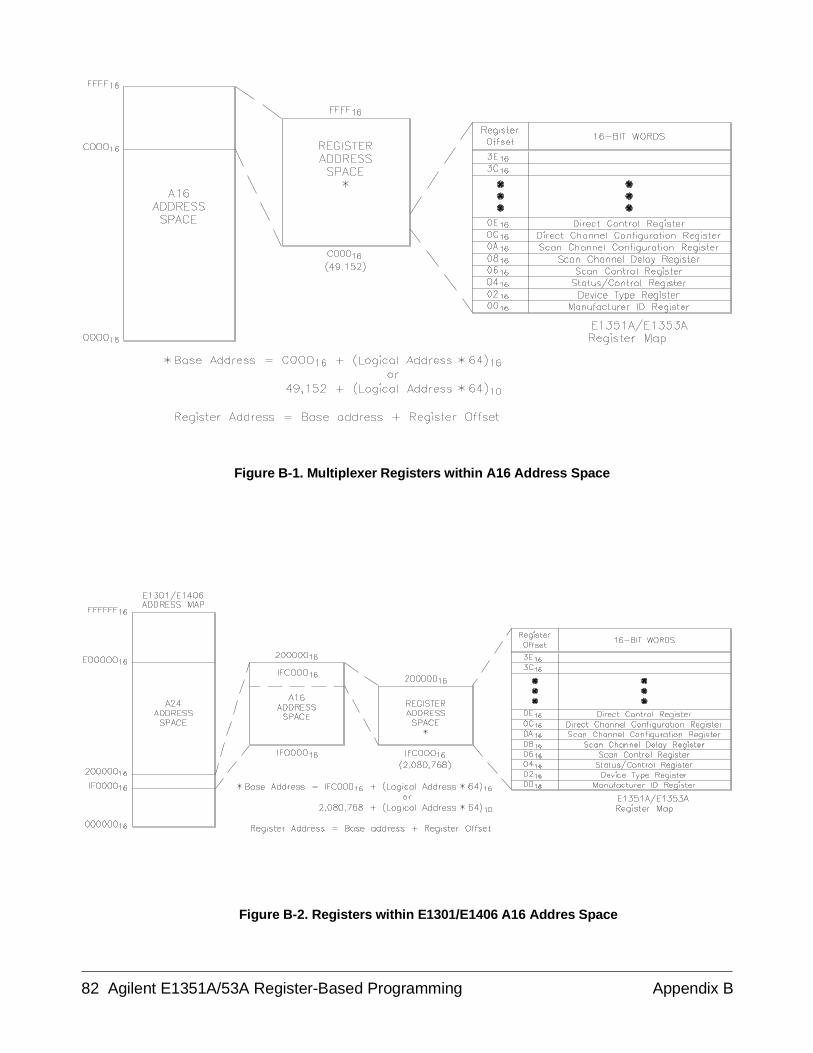
Figure B-1. Multiplexer Registers within A16 Address Space
Figure B-2. Registers within E1301/E1406 A16 Addres Space
82 Agilent E1351A/53A Register-Based Programming Appendix B

The Base Address When reading or writing to a multiplexer register, specify a hexadecimal ordecimal register address. This address consists of a base address plus aregister offset. The base address used programming depends on whether theA16 address space is outside or inside the Agilent E1405A/E1406ACommand Module or Agilent E1300B/E1301B Mainframe.
A16 Address SpaceOutside the
Command Moduleor Mainframe
When the command module or mainframe is not part of your VXIbussystem (Figure B-1), the multiplexer’s base address is computed as:*
C00016 + (LADDR * 64)16
or49,152 + (LADDR * 64)
where C00016 (49,152) is the starting location of the register addresses,LADDR is the multiplexer’s logical address, and 64 is the number ofaddress bytes per VXIbus device. For example, the multiplexer’s factoryset logical address is 112. With this address, the multiplexer has a baseaddress:
C00016 + (112 * 64)16
C00016 + 1C0016 = DC0016
or (decimal)49,152 + (112 * 64)
49,152 + 7,168 = 56,320
A16 Address SpaceInside the
Command Moduleor Mainframe
When the A16 address space is inside the command module or mainframe(Figure B-2), the multiplexer’s base address is computed as:
1FC00016 + (LADDR * 64)16
or2,080,768 + (LADDR * 64)
where 1FC00016 (2,080,768) is the starting location of the VXI A16addresses, LADDR is the multiplexer’s logical address, and 64 is thenumber of address bytes per register-based device. Again, the multiplexer’sfactory set logical address is 112. If this address is not changed, themultiplexer will have a base address of:
1FC00016 + (112 * 64)16
1FC00016 + 1C0016 = 1FDC0016
or2,080,768 + (112 * 64)
2,080,768 + 7,168 = 2,087,936
* The "16" at the end of the address indicates a hexadecimal number.
Appendix B Agilent E1351A/53A Register-Based Programming 83
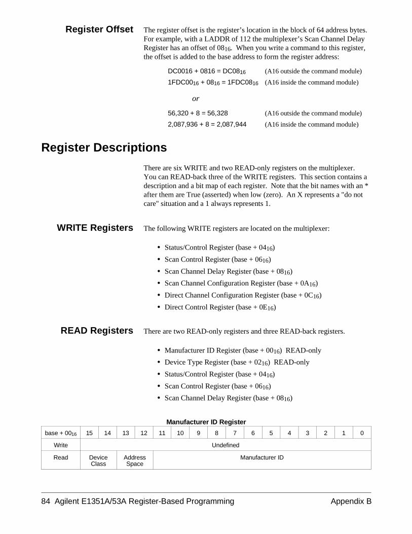
Register Offset The register offset is the register’s location in the block of 64 address bytes.For example, with a LADDR of 112 the multiplexer’s Scan Channel DelayRegister has an offset of 0816. When you write a command to this register,the offset is added to the base address to form the register address:
DC0016 + 0816 = DC0816 (A16 outside the command module)
1FDC0016 + 0816 = 1FDC0816 (A16 inside the command module)
or
56,320 + 8 = 56,328 (A16 outside the command module)
2,087,936 + 8 = 2,087,944 (A16 inside the command module)
Register Descriptions
There are six WRITE and two READ-only registers on the multiplexer.You can READ-back three of the WRITE registers. This section contains adescription and a bit map of each register. Note that the bit names with an *after them are True (asserted) when low (zero). An X represents a "do notcare" situation and a 1 always represents 1.
WRITE Registers The following WRITE registers are located on the multiplexer:
• Status/Control Register (base + 0416)
• Scan Control Register (base + 0616)
• Scan Channel Delay Register (base + 0816)
• Scan Channel Configuration Register (base + 0A16)
• Direct Channel Configuration Register (base + 0C16)
• Direct Control Register (base + 0E16)
READ Registers There are two READ-only registers and three READ-back registers.
• Manufacturer ID Register (base + 0016) READ-only
• Device Type Register (base + 0216) READ-only
• Status/Control Register (base + 0416)
• Scan Control Register (base + 0616)
• Scan Channel Delay Register (base + 0816)
Manufacturer ID Register
base + 0016 15 14 13 12 11 10 9 8 7 6 5 4 3 2 1 0
Write Undefined
Read DeviceClass
AddressSpace
Manufacturer ID
84 Agilent E1351A/53A Register-Based Programming Appendix B
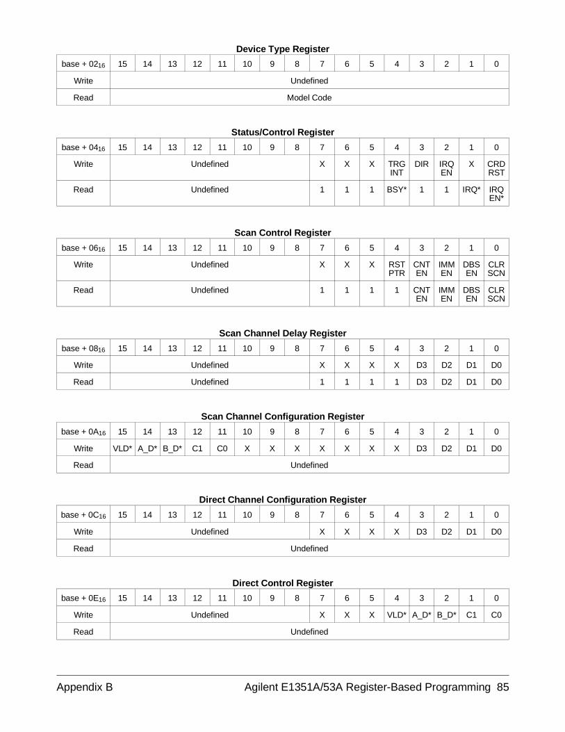
Device Type Register
base + 0216 15 14 13 12 11 10 9 8 7 6 5 4 3 2 1 0
Write Undefined
Read Model Code
Status/Control Register
base + 0416 15 14 13 12 11 10 9 8 7 6 5 4 3 2 1 0
Write Undefined X X X TRGINT
DIR IRQEN
X CRDRST
Read Undefined 1 1 1 BSY* 1 1 IRQ* IRQEN*
Scan Control Register
base + 0616 15 14 13 12 11 10 9 8 7 6 5 4 3 2 1 0
Write Undefined X X X RSTPTR
CNTEN
IMMEN
DBSEN
CLRSCN
Read Undefined 1 1 1 1 CNTEN
IMMEN
DBSEN
CLRSCN
Scan Channel Delay Register
base + 0816 15 14 13 12 11 10 9 8 7 6 5 4 3 2 1 0
Write Undefined X X X X D3 D2 D1 D0
Read Undefined 1 1 1 1 D3 D2 D1 D0
Scan Channel Configuration Register
base + 0A16 15 14 13 12 11 10 9 8 7 6 5 4 3 2 1 0
Write VLD* A_D* B_D* C1 C0 X X X X X X X D3 D2 D1 D0
Read Undefined
Direct Channel Configuration Register
base + 0C16 15 14 13 12 11 10 9 8 7 6 5 4 3 2 1 0
Write Undefined X X X X D3 D2 D1 D0
Read Undefined
Direct Control Register
base + 0E16 15 14 13 12 11 10 9 8 7 6 5 4 3 2 1 0
Write Undefined X X X VLD* A_D* B_D* C1 C0
Read Undefined
Appendix B Agilent E1351A/53A Register-Based Programming 85
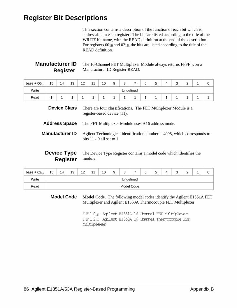
Register Bit Descriptions
This section contains a description of the function of each bit which isaddressable in each register. The bits are listed according to the title of theWRITE bit name, with the READ definition at the end of the description.For registers 0016 and 0216, the bits are listed according to the title of theREAD definition.
Manufacturer IDRegister
The 16-Channel FET Multiplexer Module always returns FFFF16 on aManufacturer ID Register READ.
base + 0016 15 14 13 12 11 10 9 8 7 6 5 4 3 2 1 0
Write Undefined
Read 1 1 1 1 1 1 1 1 1 1 1 1 1 1 1 1
Device Class There are four classifications. The FET Multiplexer Module is aregister-based device (11).
Address Space The FET Multiplexer Module uses A16 address mode.
Manufacturer ID Agilent Technologies’ identification number is 4095, which corresponds tobits 11 - 0 all set to 1.
Device TypeRegister
The Device Type Register contains a model code which identifies themodule.
base + 0216 15 14 13 12 11 10 9 8 7 6 5 4 3 2 1 0
Write Undefined
Read Model Code
Model Code Model Code. The following model codes identify the Agilent E1351A FETMultiplexer and Agilent E1353A Thermocouple FET Multiplexer:
FF1016 Agilent E1351A 16-Channel FET MultiplexerFF1216 Agilent E1353A 16-Channel Thermocouple FETMultiplexer
86 Agilent E1351A/53A Register-Based Programming Appendix B
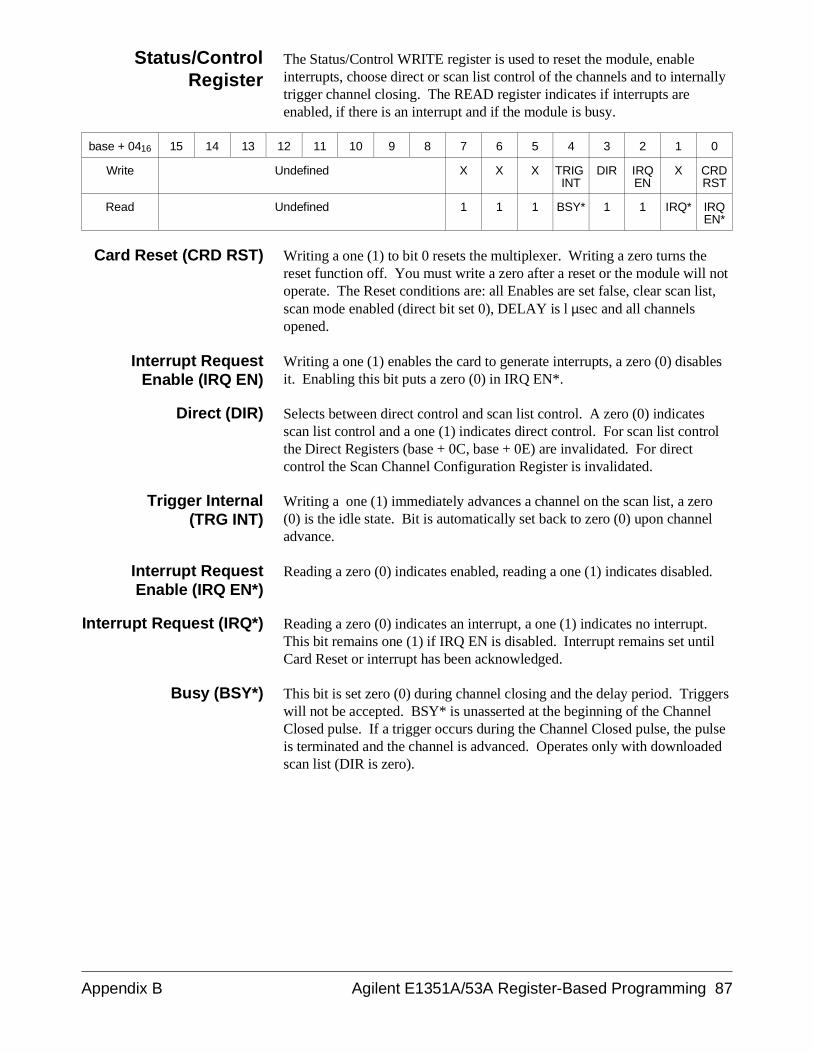
Status/ControlRegister
The Status/Control WRITE register is used to reset the module, enableinterrupts, choose direct or scan list control of the channels and to internallytrigger channel closing. The READ register indicates if interrupts areenabled, if there is an interrupt and if the module is busy.
base + 0416 15 14 13 12 11 10 9 8 7 6 5 4 3 2 1 0
Write Undefined X X X TRIG INT
DIR IRQEN
X CRDRST
Read Undefined 1 1 1 BSY* 1 1 IRQ* IRQEN*
Card Reset (CRD RST) Writing a one (1) to bit 0 resets the multiplexer. Writing a zero turns thereset function off. You must write a zero after a reset or the module will notoperate. The Reset conditions are: all Enables are set false, clear scan list,scan mode enabled (direct bit set 0), DELAY is l µsec and all channelsopened.
Interrupt RequestEnable (IRQ EN)
Writing a one (1) enables the card to generate interrupts, a zero (0) disablesit. Enabling this bit puts a zero (0) in IRQ EN*.
Direct (DIR) Selects between direct control and scan list control. A zero (0) indicatesscan list control and a one (1) indicates direct control. For scan list controlthe Direct Registers (base + 0C, base + 0E) are invalidated. For directcontrol the Scan Channel Configuration Register is invalidated.
Trigger Internal(TRG INT)
Writing a one (1) immediately advances a channel on the scan list, a zero(0) is the idle state. Bit is automatically set back to zero (0) upon channeladvance.
Interrupt RequestEnable (IRQ EN*)
Reading a zero (0) indicates enabled, reading a one (1) indicates disabled.
Interrupt Request (IRQ*) Reading a zero (0) indicates an interrupt, a one (1) indicates no interrupt.This bit remains one (1) if IRQ EN is disabled. Interrupt remains set untilCard Reset or interrupt has been acknowledged.
Busy (BSY*) This bit is set zero (0) during channel closing and the delay period. Triggerswill not be accepted. BSY* is unasserted at the beginning of the ChannelClosed pulse. If a trigger occurs during the Channel Closed pulse, the pulseis terminated and the channel is advanced. Operates only with downloadedscan list (DIR is zero).
Appendix B Agilent E1351A/53A Register-Based Programming 87
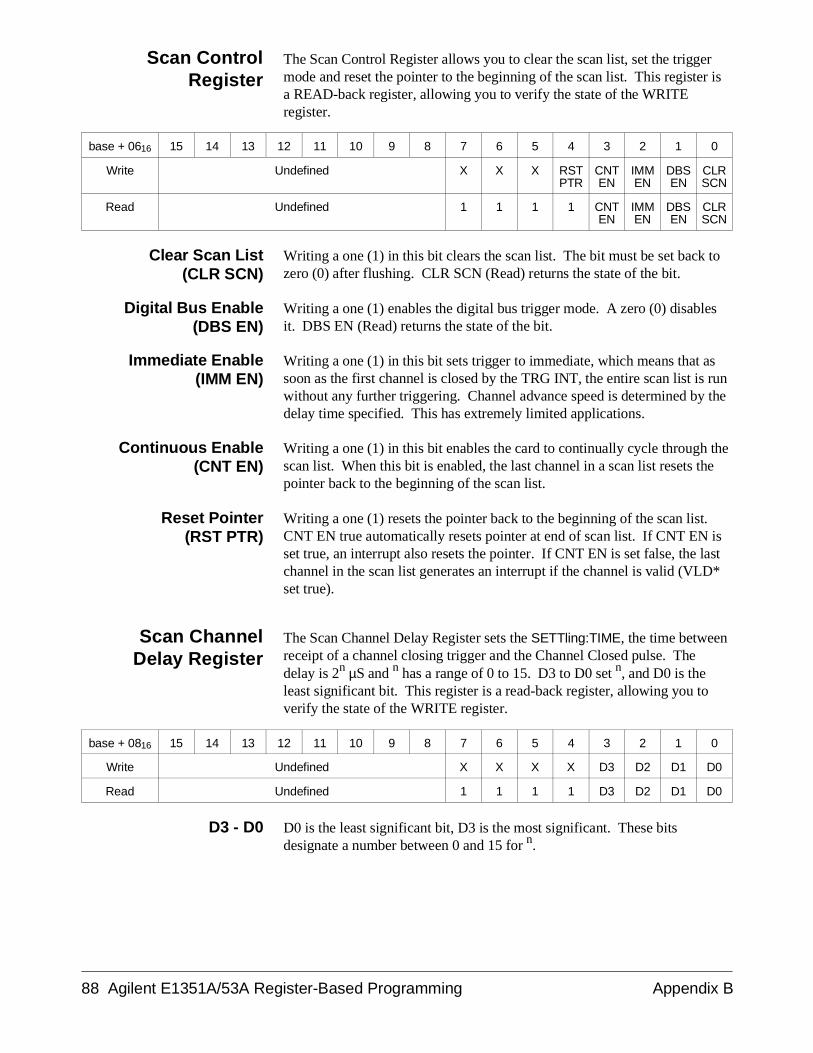
Scan ControlRegister
The Scan Control Register allows you to clear the scan list, set the triggermode and reset the pointer to the beginning of the scan list. This register isa READ-back register, allowing you to verify the state of the WRITEregister.
base + 0616 15 14 13 12 11 10 9 8 7 6 5 4 3 2 1 0
Write Undefined X X X RSTPTR
CNTEN
IMMEN
DBSEN
CLRSCN
Read Undefined 1 1 1 1 CNTEN
IMMEN
DBSEN
CLRSCN
Clear Scan List(CLR SCN)
Writing a one (1) in this bit clears the scan list. The bit must be set back tozero (0) after flushing. CLR SCN (Read) returns the state of the bit.
Digital Bus Enable(DBS EN)
Writing a one (1) enables the digital bus trigger mode. A zero (0) disablesit. DBS EN (Read) returns the state of the bit.
Immediate Enable(IMM EN)
Writing a one (1) in this bit sets trigger to immediate, which means that assoon as the first channel is closed by the TRG INT, the entire scan list is runwithout any further triggering. Channel advance speed is determined by thedelay time specified. This has extremely limited applications.
Continuous Enable(CNT EN)
Writing a one (1) in this bit enables the card to continually cycle through thescan list. When this bit is enabled, the last channel in a scan list resets thepointer back to the beginning of the scan list.
Reset Pointer(RST PTR)
Writing a one (1) resets the pointer back to the beginning of the scan list.CNT EN true automatically resets pointer at end of scan list. If CNT EN isset true, an interrupt also resets the pointer. If CNT EN is set false, the lastchannel in the scan list generates an interrupt if the channel is valid (VLD*set true).
Scan ChannelDelay Register
The Scan Channel Delay Register sets the SETTling:TIME, the time betweenreceipt of a channel closing trigger and the Channel Closed pulse. Thedelay is 2n µS and n has a range of 0 to 15. D3 to D0 set n, and D0 is theleast significant bit. This register is a read-back register, allowing you toverify the state of the WRITE register.
base + 0816 15 14 13 12 11 10 9 8 7 6 5 4 3 2 1 0
Write Undefined X X X X D3 D2 D1 D0
Read Undefined 1 1 1 1 D3 D2 D1 D0
D3 - D0 D0 is the least significant bit, D3 is the most significant. These bitsdesignate a number between 0 and 15 for n.
88 Agilent E1351A/53A Register-Based Programming Appendix B
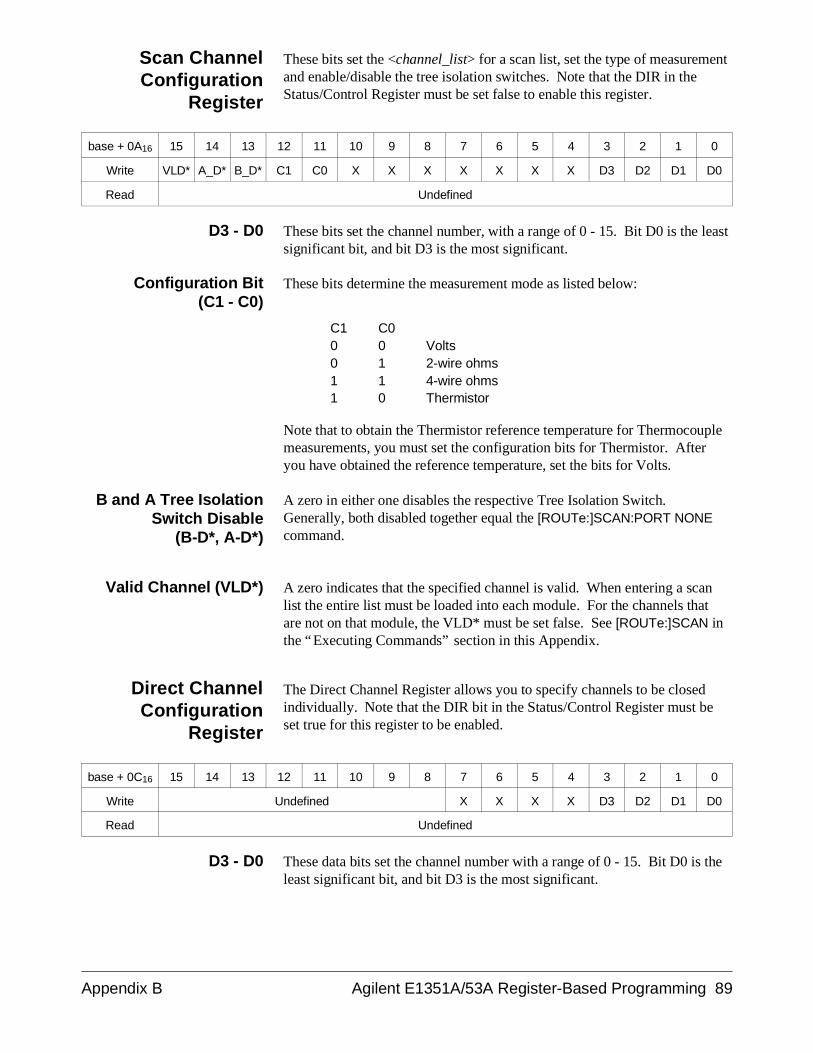
Scan ChannelConfiguration
Register
These bits set the <channel_list> for a scan list, set the type of measurementand enable/disable the tree isolation switches. Note that the DIR in theStatus/Control Register must be set false to enable this register.
base + 0A16 15 14 13 12 11 10 9 8 7 6 5 4 3 2 1 0
Write VLD* A_D* B_D* C1 C0 X X X X X X X D3 D2 D1 D0
Read Undefined
D3 - D0 These bits set the channel number, with a range of 0 - 15. Bit D0 is the leastsignificant bit, and bit D3 is the most significant.
Configuration Bit(C1 - C0)
These bits determine the measurement mode as listed below:
C1 C0 0 0 Volts0 1 2-wire ohms1 1 4-wire ohms 1 0 Thermistor
Note that to obtain the Thermistor reference temperature for Thermocouplemeasurements, you must set the configuration bits for Thermistor. Afteryou have obtained the reference temperature, set the bits for Volts.
B and A Tree IsolationSwitch Disable
(B-D*, A-D*)
A zero in either one disables the respective Tree Isolation Switch.Generally, both disabled together equal the [ROUTe:]SCAN:PORT NONEcommand.
Valid Channel (VLD*) A zero indicates that the specified channel is valid. When entering a scanlist the entire list must be loaded into each module. For the channels thatare not on that module, the VLD* must be set false. See [ROUTe:]SCAN inthe “Executing Commands” section in this Appendix.
Direct ChannelConfiguration
Register
The Direct Channel Register allows you to specify channels to be closedindividually. Note that the DIR bit in the Status/Control Register must beset true for this register to be enabled.
base + 0C16 15 14 13 12 11 10 9 8 7 6 5 4 3 2 1 0
Write Undefined X X X X D3 D2 D1 D0
Read Undefined
D3 - D0 These data bits set the channel number with a range of 0 - 15. Bit D0 is theleast significant bit, and bit D3 is the most significant.
Appendix B Agilent E1351A/53A Register-Based Programming 89
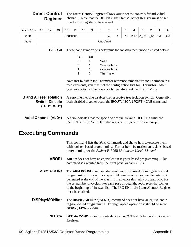
Direct ControlRegister
The Direct Control Register allows you to set the controls for individualchannels. Note that the DIR bit in the Status/Control Register must be settrue for this register to be enabled.
base + 0E16 15 14 13 12 11 10 9 8 7 6 5 4 3 2 1 0
Write Undefined X X X VLD* A_D* B_D* C1 C0
Read Undefined
C1 - C0 These configuration bits determine the measurement mode as listed below:
C1 C0 0 0 Volts0 1 2-wire ohms1 1 4-wire ohms 1 0 Thermistor
Note that to obtain the Thermistor reference temperature for Thermocouplemeasurements, you must set the configuration bits for Thermistor. Afteryou have obtained the reference temperature, set the bits for Volts.
B and A Tree IsolationSwitch Disable
(B-D*, A-D*)
A zero in either one disables the respective tree isolation switch. Generally,both disabled together equal the [ROUTe:]SCAN:PORT NONE command.
Valid Channel (VLD*) A zero indicates that the specified channel is valid. If DIR is valid and INT EN is true, a WRITE to this register will generate an interrupt.
Executing Commands
This command lists the SCPI commands and shows how to execute themwith register-based programming. For further information on register-basedprogramming see the Agilent E1326B Multimeter User’s Manual.
ABORt ABORt does not have an equivalent in register-based programming. Thiscommand is executed from the front panel or over GPIB.
ARM:COUNt The ARM:COUNt command does not have an equivalent in register-basedprogramming. To scan for a specified number of cycles, use the interruptgenerated at the end of the scan list to advance through a program loop forthe set number of cycles. For each pass through the loop, reset the pointerto the beginning of the scan list. The IRQ EN in the Status/Control Registermust be enabled.
DISPlay:MONitor The DISPlay:MONitor[:STATe] command does not have an equivalent inregister-based programming. For high-speed operation it should be set toDISPlay:MONitor OFF.
INITiate INITiate:CONTinuous is equivalent to the CNT EN bit in the Scan ControlRegister.
90 Agilent E1351A/53A Register-Based Programming Appendix B
INITiate[:IMMediate] is equivalent to writing a one to the TRG INT in theStatus/Control Register. The TRG INT sets itself back to zero after pulsingthe FET. If you have a multiple-module configuration and a downloadedscan list, the module with the first channel on the scan list must be the lastone to receive the TRG INT. The scan cycle will start as soon as the cardwith a valid channel receives TRG INT.
OUTPut The OUTPut[:STATe] command does not have an equivalent inregister-based programming.
[ROUTe:] [ROUTe:]CLOSe <channel_list> is equivalent to the following:
• DIR in the Status/Control Register is enabled.• D0 to D3 is set to a channel number in the Direct Channel
Configuration Register.
[ROUTe:]OPEN <channel_list> can be implemented by setting VLD* falsein either the Scan Channel Configuration Register or the Direct ControlRegister (whichever one closed the channel). It can also be implemented bytoggling the DIR bit in the Status/Control Register.
For [ROUTe:]SCAN <channel_list>, the complete scan list must be loadedin each module in a multiple-module configuration. The channel is set validif it is in that module, and invalid in the other modules. The channel list isdownloaded in the following way:
• Set CLR SCN in Scan Control Register to one, then back to zero, toclear the previous scan list.
• DIR in the Status/Control Register is set to false.
• Channel number is set in D0 to D3 in the Scan ChannelConfiguration Register.
The example below shows how to set a scan list for channels(@100,101,200,201):
• Write to the Scan Channel Configuration Register on card 1:
VLD* true (0), 0000 to D3-D0 Sets channel 100.
VLD* true (0), 0001 to D3-D0 Sets channel 101.
VLD* false (1), XXXX to D3-D0 Reserves position in scan list forchannel 200.
VLD* false (1), XXXX to D3-D0 Reserves position in scan list forchannel 201.
• Write to the Scan Channel Configuration Register on card 2:
VLD* false (1), XXXX to D3-D0 Reserves position in scan list forchannel 100.
VLD* false (1), XXXX to D3-D0 Reserves position in scan list forchannel 101.
VLD* true (0), 0000 to D3-D0 Sets channel 200.
VLD* true (0), 0001 to D3-D0 Sets channel 201.
Appendix B Agilent E1351A/53A Register-Based Programming 91
The [ROUTe:]SCAN:MODE VOLT | RES | FRES is set with C1 and C0 inthe Scan Channel or Direct Control Register. Note that to obtain theThermistor reference temperature for Thermocouple measurements, youmust set the configuration bits for Thermistor. After you have obtained thereference temperature, set the bits for Volts.
C1 C0 0 0 Volts0 1 2-wire ohms1 1 4-wire ohms 1 0 Thermistor
[ROUTe:]SCAN:PORT NONE | ABUS is set with A_D* and B_D* on theScan Channel Configuration or Direct Control Registers. Set both bits toone for ABUS and to zero for NONE.
[ROUTe:]SETTling[:TIME] is set with the D3 to D0 bits in the ScanChannel Delay Register. The bits form a number n (n is between 0 and 16),and the delay is 2n µsec.
SYSTem SYSTem:CDEScription? is a READ on the Manufacturer ID Register.
SYSTem:CTYPe? is a READ on the Device Type Register.
SYSTem:CPON can be achieved by setting the DIR bit true in theStatus/Control Register and setting VLD* false. This opens all channelswithout a card reset.
TRIGger TRIGger[:IMMediate] is equivalent to writing a one to TRG INT in theStatus Control Register. The register returns to zero after pulsing thechannel.
TRIGger:SOURce IMMediate and TRIGger:SOURce DBUS are executedwith the IMM EN and DBS EN bits in the Scan Control Register.
TRIGger:SOURce BUS and TRIGger:SOURce EXTernal are notimplemented at the register level. These commands both write to the TRGINT bit when they are active and a trigger occurs.
TRIGger:SOURce HOLD is not implemented at the register level. It is inthe normal state when all trigger sources are disabled.
92 Agilent E1351A/53A Register-Based Programming Appendix B
Register-Based Programming for Maximum Speed
This is an outline of the algorithm that needs to be followed to have theAgilent E1326B 51⁄2 Digit Multimeter do high-speed scanning using theAgilent E1351A 16-Channel FET Multiplexer. This procedure programs the multimeter and downloads a scan list to the FET multiplexer so thehardware controls the entire scanning process. The Agilent E1326B hasseveral things that should be understood when doing register programming.
1. Table B-1 on page 96 lists the multimeter’s commands. When doingany of these commands, you are writing to registers which are read by themultimeter’s voltmeter microprocessor. It is important to follow theprocedure in Figure B-3 on page 97 on how to send commands. This willenable you to handshake with the E1326B microprocessor as you can easilywrite commands faster than the processor can execute them.
2. In order to program the Agilent E1326B Multimeter to take readingswith the Agilent E1351A FET Multiplexer at its highest speed, do thecommands from Table B-1 on page 96. Note that all values in Table B-1are specified in decimal.
set the function dcvset the range 1VNote: You must have a fixed range to do 13k. Auto range will do 2.5k.set the aperture 10 µsecNote: This will cause readings to be returned as 16 bits.set the auto zero off or onceset offset Compensation offset trigger source Immediateset trigger count 1set trigger delay 0set Sample Count 16This should be the total number of A/D readings that you will take(for example, once through a 16 channel list = 16, 10 times througha 16 channel list = 160).set sample Source TimerThis is the time between A/D readings.set sample Period 76µs76 µsec is the minimum or fastest A/D time.set trigger arm armedThis arms the DVM to take all of the reading specified above.
Do not execute the next command yet. You still need to set the scan list inthe Agilent E1351A. Trigger immediate will start everything.
3. Now download the channel list to the Agilent E1351A
• Set CLR SCN in Scan Control Register to one, then back to zero inorder to clear the previous scan list.
• DIR in the Status/Control Register set to false.
Appendix B Agilent E1351A/53A Register-Based Programming 93
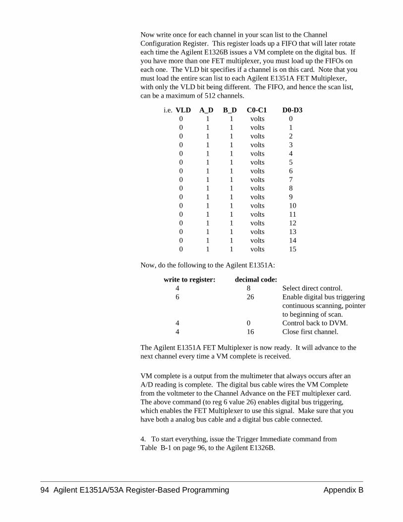
Now write once for each channel in your scan list to the ChannelConfiguration Register. This register loads up a FIFO that will later rotateeach time the Agilent E1326B issues a VM complete on the digital bus. Ifyou have more than one FET multiplexer, you must load up the FIFOs oneach one. The VLD bit specifies if a channel is on this card. Note that youmust load the entire scan list to each Agilent E1351A FET Multiplexer,with only the VLD bit being different. The FIFO, and hence the scan list,can be a maximum of 512 channels.
i.e. VLD A_D B_D C0-C1 D0-D3 0 1 1 volts 0 0 1 1 volts 1 0 1 1 volts 2 0 1 1 volts 3 0 1 1 volts 4 0 1 1 volts 5 0 1 1 volts 6 0 1 1 volts 7 0 1 1 volts 8 0 1 1 volts 9 0 1 1 volts 10 0 1 1 volts 11 0 1 1 volts 12 0 1 1 volts 13 0 1 1 volts 14 0 1 1 volts 15
Now, do the following to the Agilent E1351A:
write to register: decimal code:4 8 Select direct control.6 26 Enable digital bus triggering
continuous scanning, pointerto beginning of scan.
4 0 Control back to DVM.4 16 Close first channel.
The Agilent E1351A FET Multiplexer is now ready. It will advance to thenext channel every time a VM complete is received.
VM complete is a output from the multimeter that always occurs after anA/D reading is complete. The digital bus cable wires the VM Completefrom the voltmeter to the Channel Advance on the FET multiplexer card.The above command (to reg 6 value 26) enables digital bus triggering,which enables the FET Multiplexer to use this signal. Make sure that youhave both a analog bus cable and a digital bus cable connected.
4. To start everything, issue the Trigger Immediate command from Table B-1 on page 96, to the Agilent E1326B.
94 Agilent E1351A/53A Register-Based Programming Appendix B
The number of readings specified in sample count will now be taken. If thesample count is more than one scan, the scan list will start over again.
5. The voltmeter is now taking data which is being stored in the AgilentE1326B hardware FIFO. With the 10 µsec aperture set, 512 16-bit readingswill collect here. In any other aperture only 256 32-bit readings will collect.If you specified more than 512 readings, the computer needs to be removingthem from the FIFO while readings are being taken. The DVM FIFO isconnected to the Agilent E1326B VXI DATA BUFFER register.
To read the FIFO check the Data Ready bit in the Status Register todetermine if valid data is in the Data Buffer. Or, read the Data Buffer andthrow away any -1 readings, as a -1 decimal reading or all bits set to "1"indicates invalid data. Keep reading the Data Buffer until you receive thenumber of readings specified in Sample Count. Convert the readings fromvoltmeter format to 32-bit real format.
6. To do debugging with the Agilent E1326B voltmeter, use the QueryOpcodes in Table B-1. This will verify that you have set the correctparameters. Use the Send Error command (15) to get error codes back.Refer to Table B-2 on page 98.
With the Agilent E1351A you cannot read back the contents in the FIFO,therefore, debugging is difficult. Do verify that you get correct data backfrom the Manufacturer ID Register and Device Type Register.
Appendix B Agilent E1351A/53A Register-Based Programming 95
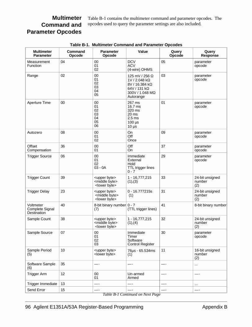
MultimeterCommand and
Parameter Opcodes
Table B-1 contains the multimeter command and parameter opcodes. Theopcodes used to query the parameter settings are also included.
Table B-1. Multimeter Command and Parameter Opcodes
MultimeterParameter
CommandOpcode
ParameterOpcode
Value QueryOpcode
QueryResponse
MeasurementFunction
04 000102
DCVACV(4-wire) OHMS
05 parameteropcode
Range 02 000102030405
125 mV / 256 Ω1V / 2.048 kΩ8V / 16.384 kΩ64V / 131 kΩ300V / 1.048 MΩAutorange
03 parameteropcode
Aperture Time 00 00010203040506
267 ms16.7 ms320 ms20 ms2.5 ms100 µs10 µs
01 parameteropcode
Autozero 08 000102
OnOffOnce
09 parameteropcode
OffsetCompensation
36 0001
OffOn
37 parameteropcode
Trigger Source 06 00010203 - 0A
ImmediateExternalHoldTTL trigger lines0 - 7
29 parameteropcode
Trigger Count 39 <upper byte><middle byte> <lower byte>
1 - 16,777,215(1),(3)
33 24-bit unsignednumber(2)
Trigger Delay 23 <upper byte> <middle byte> <lower byte>
0 - 16.777215s (1)
31 24-bit unsignednumber(2)
VoltmeterComplete SignalDestination
40 8-bit binary number(7)
0 - 7(TTL trigger lines)
41 8-bit binary number
Sample Count 38 <upper byte><middle byte> <lower byte>
1 - 16,777,215(1),(4)
32 24-bit unsignednumber(2)
Sample Source 07 00010203
ImmediateTimerSoftwareControl Register
30 parameteropcode
Sample Period(5)
10 <upper byte><lower byte>
76µs - 65.534ms(1)
11 16-bit unsignednumber(2)
Software Sample(6)
35 —- —- —- ...
Trigger Arm 12 0001
Un-armedArmed
—- —-
Trigger Immediate 13 —- —- —- ...
Send Error 15 —- —- —- —-Table B-1 Continued on Next Page
96 Agilent E1351A/53A Register-Based Programming Appendix B
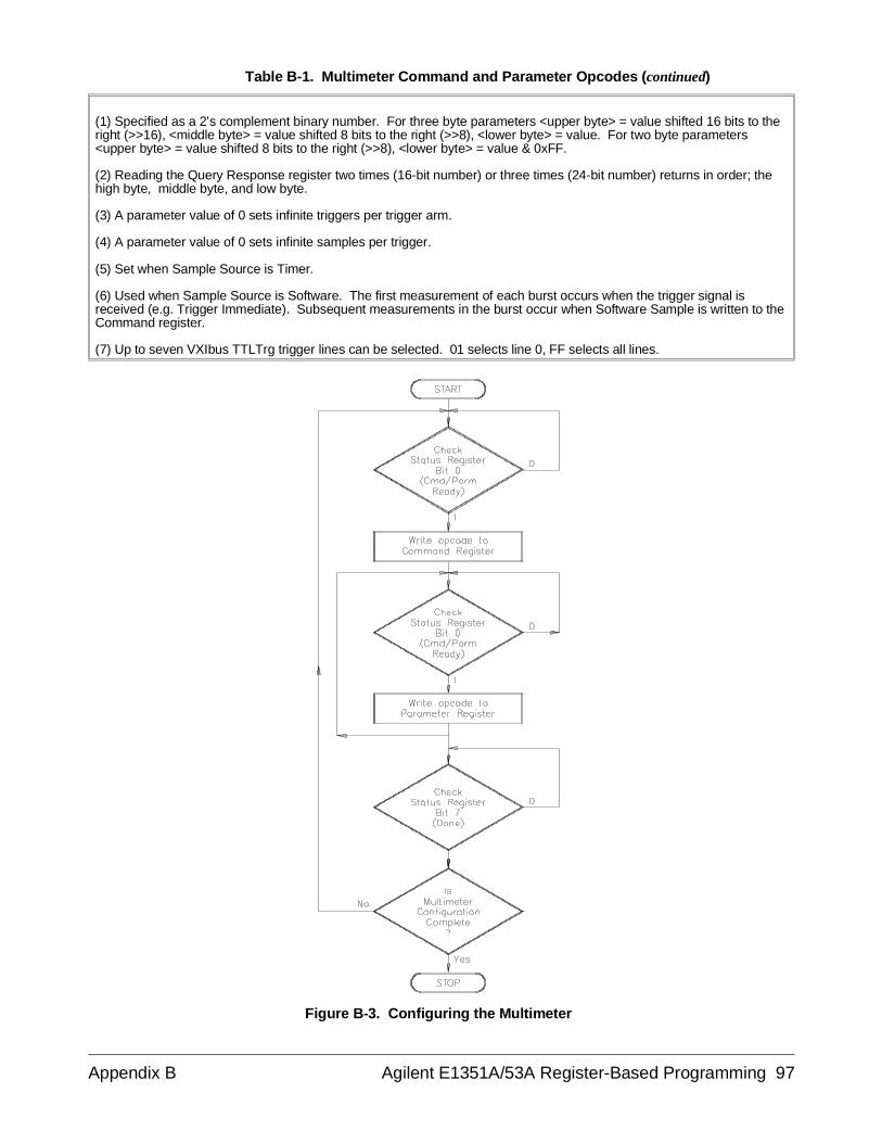
Table B-1. Multimeter Command and Parameter Opcodes (continued)
(1) Specified as a 2’s complement binary number. For three byte parameters <upper byte> = value shifted 16 bits to theright (>>16), <middle byte> = value shifted 8 bits to the right (>>8), <lower byte> = value. For two byte parameters<upper byte> = value shifted 8 bits to the right (>>8), <lower byte> = value & 0xFF.
(2) Reading the Query Response register two times (16-bit number) or three times (24-bit number) returns in order; thehigh byte, middle byte, and low byte.
(3) A parameter value of 0 sets infinite triggers per trigger arm.
(4) A parameter value of 0 sets infinite samples per trigger.
(5) Set when Sample Source is Timer.
(6) Used when Sample Source is Software. The first measurement of each burst occurs when the trigger signal isreceived (e.g. Trigger Immediate). Subsequent measurements in the burst occur when Software Sample is written to theCommand register.
(7) Up to seven VXIbus TTLTrg trigger lines can be selected. 01 selects line 0, FF selects all lines.
Figure B-3. Configuring the Multimeter
Appendix B Agilent E1351A/53A Register-Based Programming 97
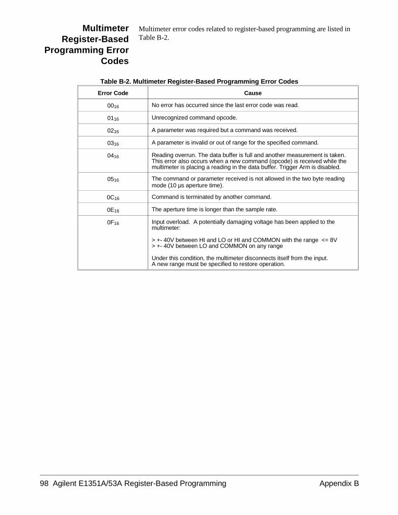
MultimeterRegister-Based
Programming ErrorCodes
Multimeter error codes related to register-based programming are listed inTable B-2.
Table B-2. Multimeter Register-Based Programming Error Codes
Error Code Cause
0016 No error has occurred since the last error code was read.
0116 Unrecognized command opcode.
0216 A parameter was required but a command was received.
0316 A parameter is invalid or out of range for the specified command.
0416 Reading overrun. The data buffer is full and another measurement is taken.This error also occurs when a new command (opcode) is received while themultimeter is placing a reading in the data buffer. Trigger Arm is disabled.
0516 The command or parameter received is not allowed in the two byte readingmode (10 µs aperture time).
0C16 Command is terminated by another command.
0E16 The aperture time is longer than the sample rate.
0F16 Input overload. A potentially damaging voltage has been applied to themultimeter:
> +- 40V between HI and LO or HI and COMMON with the range <= 8V> +- 40V between LO and COMMON on any range
Under this condition, the multimeter disconnects itself from the input. A new range must be specified to restore operation.
98 Agilent E1351A/53A Register-Based Programming Appendix B
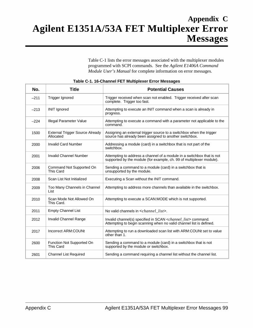
Appendix CAgilent E1351A/53A FET Multiplexer Error
Messages
Table C-1 lists the error messages associated with the multiplexer modulesprogrammed with SCPI commands. See the Agilent E1406A CommandModule User’s Manual for complete information on error messages.
Table C-1. 16-Channel FET Multiplexer Error Messages
No. Title Potential Causes
–211 Trigger Ignored Trigger received when scan not enabled. Trigger received after scancomplete. Trigger too fast.
–213 INIT Ignored Attempting to execute an INIT command when a scan is already inprogress.
–224 Illegal Parameter Value Attempting to execute a command with a parameter not applicable to thecommand.
1500 External Trigger Source AlreadyAllocated
Assigning an external trigger source to a switchbox when the triggersource has already been assigned to another switchbox.
2000 Invalid Card Number Addressing a module (card) in a switchbox that is not part of theswitchbox.
2001 Invalid Channel Number Attempting to address a channel of a module in a switchbox that is notsupported by the module (for example, ch. 99 of multiplexer module).
2006 Command Not Supported OnThis Card
Sending a command to a module (card) in a switchbox that isunsupported by the module.
2008 Scan List Not Initialized Executing a Scan without the INIT command.
2009 Too Many Channels in ChannelList
Attempting to address more channels than available in the switchbox.
2010 Scan Mode Not Allowed OnThis Card.
Attempting to execute a SCAN:MODE which is not supported.
2011 Empty Channel List No valid channels in <channel_list>.
2012 Invalid Channel Range Invalid channel(s) specified in SCAN <channel_list> command.Attempting to begin scanning when no valid channel list is defined.
2017 Incorrect ARM:COUNt Attempting to run a downloaded scan list with ARM:COUNt set to valueother than 1.
2600 Function Not Supported OnThis Card
Sending a command to a module (card) in a switchbox that is notsupported by the module or switchbox.
2601 Channel List Required Sending a command requiring a channel list without the channel list.
Appendix C Agilent E1351A/53A FET Multiplexer Error Messages 99

Notes
100 Agilent E1351A/53A FET Multiplexer Error Messages Appendix C
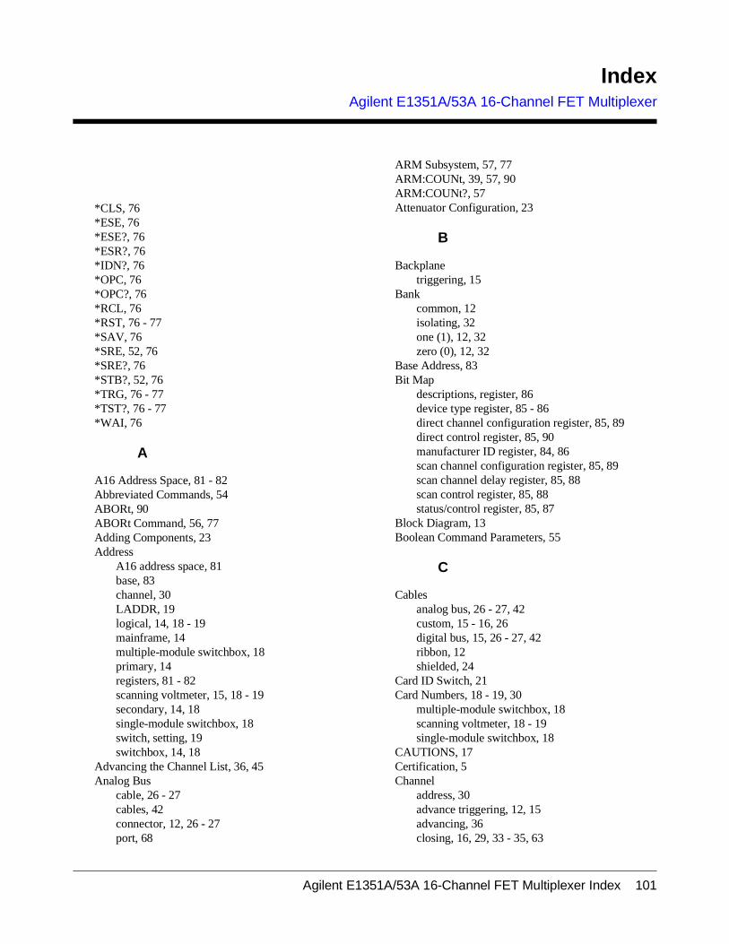
IndexAgilent E1351A/53A 16-Channel FET Multiplexer
*CLS, 76*ESE, 76*ESE?, 76*ESR?, 76*IDN?, 76*OPC, 76*OPC?, 76*RCL, 76*RST, 76 - 77*SAV, 76*SRE, 52, 76*SRE?, 76*STB?, 52, 76*TRG, 76 - 77*TST?, 76 - 77*WAI, 76
A
A16 Address Space, 81 - 82Abbreviated Commands, 54ABORt, 90ABORt Command, 56, 77Adding Components, 23Address
A16 address space, 81base, 83channel, 30LADDR, 19logical, 14, 18 - 19mainframe, 14multiple-module switchbox, 18primary, 14registers, 81 - 82scanning voltmeter, 15, 18 - 19secondary, 14, 18single-module switchbox, 18switch, setting, 19switchbox, 14, 18
Advancing the Channel List, 36, 45Analog Bus
cable, 26 - 27cables, 42connector, 12, 26 - 27port, 68
ARM Subsystem, 57, 77ARM:COUNt, 39, 57, 90ARM:COUNt?, 57Attenuator Configuration, 23
B
Backplanetriggering, 15
Bankcommon, 12isolating, 32one (1), 12, 32zero (0), 12, 32
Base Address, 83Bit Map
descriptions, register, 86device type register, 85 - 86direct channel configuration register, 85, 89direct control register, 85, 90manufacturer ID register, 84, 86scan channel configuration register, 85, 89scan channel delay register, 85, 88scan control register, 85, 88status/control register, 85, 87
Block Diagram, 13Boolean Command Parameters, 55
C
Cablesanalog bus, 26 - 27, 42custom, 15 - 16, 26digital bus, 15, 26 - 27, 42ribbon, 12shielded, 24
Card ID Switch, 21Card Numbers, 18 - 19, 30
multiple-module switchbox, 18scanning voltmeter, 18 - 19single-module switchbox, 18
CAUTIONS, 17Certification, 5Channel
address, 30advance triggering, 12, 15advancing, 36closing, 16, 29, 33 - 35, 63
Agilent E1351A/53A 16-Channel FET Multiplexer Index 101
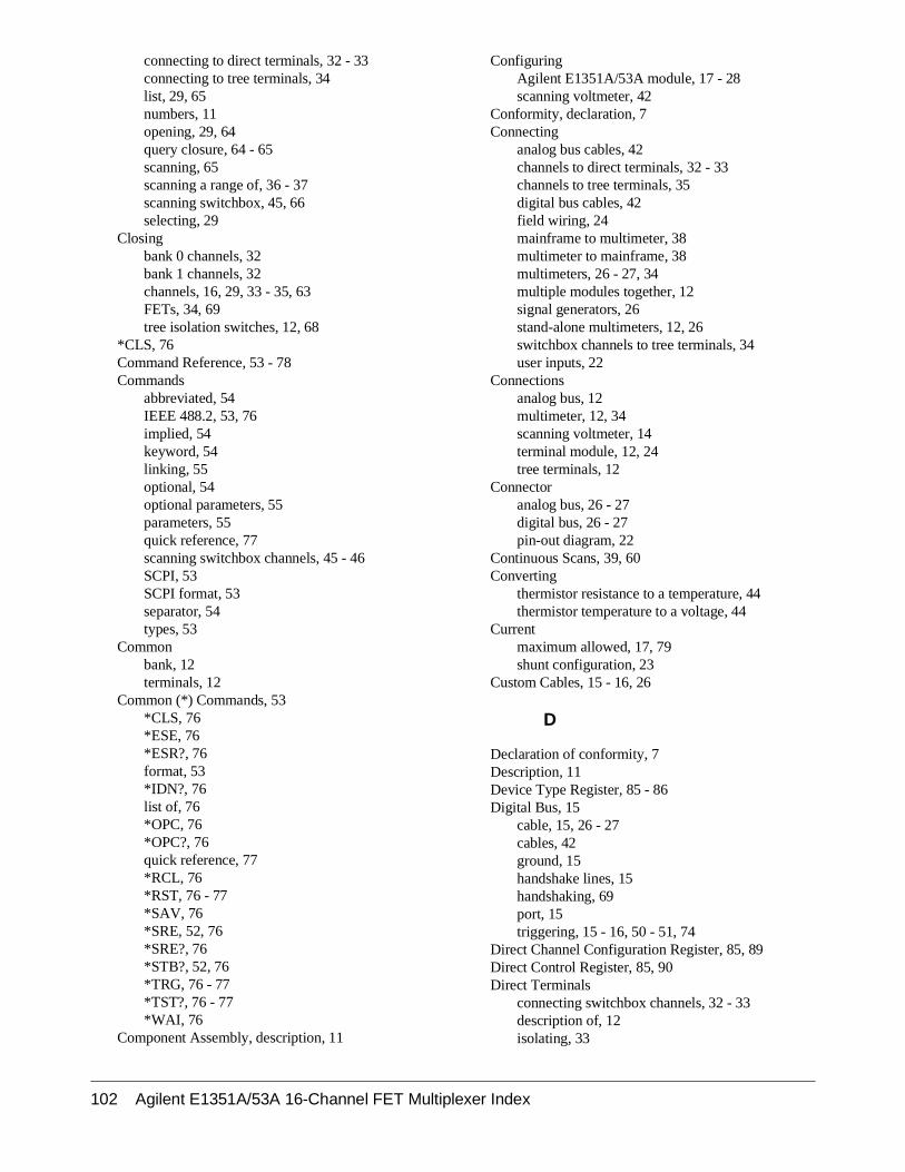
connecting to direct terminals, 32 - 33connecting to tree terminals, 34list, 29, 65numbers, 11opening, 29, 64query closure, 64 - 65scanning, 65scanning a range of, 36 - 37scanning switchbox, 45, 66selecting, 29
Closingbank 0 channels, 32bank 1 channels, 32channels, 16, 29, 33 - 35, 63FETs, 34, 69tree isolation switches, 12, 68
*CLS, 76Command Reference, 53 - 78Commands
abbreviated, 54IEEE 488.2, 53, 76implied, 54keyword, 54linking, 55optional, 54optional parameters, 55parameters, 55quick reference, 77scanning switchbox channels, 45 - 46SCPI, 53SCPI format, 53separator, 54types, 53
Commonbank, 12terminals, 12
Common (*) Commands, 53*CLS, 76*ESE, 76*ESR?, 76format, 53*IDN?, 76list of, 76*OPC, 76*OPC?, 76quick reference, 77*RCL, 76*RST, 76 - 77*SAV, 76*SRE, 52, 76*SRE?, 76*STB?, 52, 76*TRG, 76 - 77*TST?, 76 - 77*WAI, 76
Component Assembly, description, 11
ConfiguringAgilent E1351A/53A module, 17 - 28scanning voltmeter, 42
Conformity, declaration, 7Connecting
analog bus cables, 42channels to direct terminals, 32 - 33channels to tree terminals, 35digital bus cables, 42field wiring, 24mainframe to multimeter, 38multimeter to mainframe, 38multimeters, 26 - 27, 34multiple modules together, 12signal generators, 26stand-alone multimeters, 12, 26switchbox channels to tree terminals, 34user inputs, 22
Connectionsanalog bus, 12multimeter, 12, 34scanning voltmeter, 14terminal module, 12, 24tree terminals, 12
Connectoranalog bus, 26 - 27digital bus, 26 - 27pin-out diagram, 22
Continuous Scans, 39, 60Converting
thermistor resistance to a temperature, 44thermistor temperature to a voltage, 44
Currentmaximum allowed, 17, 79shunt configuration, 23
Custom Cables, 15 - 16, 26
D
Declaration of conformity, 7Description, 11Device Type Register, 85 - 86Digital Bus, 15
cable, 15, 26 - 27cables, 42ground, 15handshake lines, 15handshaking, 69port, 15triggering, 15 - 16, 50 - 51, 74
Direct Channel Configuration Register, 85, 89Direct Control Register, 85, 90Direct Terminals
connecting switchbox channels, 32 - 33description of, 12isolating, 33
102 Agilent E1351A/53A 16-Channel FET Multiplexer Index
Direct Terminals (continued)measurement accuracy, 33
Discrete Command Parameters, 55DISPlay Subsystem, 58 - 59, 77DISPlay:MONitor:CARD, 58DISPlay:MONitor[:STATe], 59, 90Documentation history, 6Downloading Scan List, 39 - 41, 65
E
Errorscodes, register-based, 98messages, 72, 99 - 100numbers, 72, 99 - 100queue, 72
*ESE, 76*ESE?, 76*ESR?, 76Event In Port, 15, 45, 74
scanning with, 49trigger input, 75
Examplesconnecting channels to tree terminals, 35making 2-wire ohms measurements by scanning, 38making 4-wire ohms measurements by scanning, 38making multiple scans, 39making voltage measurements by scanning, 36 - 37scan complete monitor, 52scanning using "Trig Out" and "Event In" ports, 49scanning using digital bus triggering, 50 - 51scanning using scanning voltmeter, 51scanning using stand-alone multimeter, 50scanning with external instruments, 48
Executing Commands, 90External
instruments, scanning with, 45, 48 - 50, 66trigger inputs, 74trigger port, 48 - 50triggering, 15
F
Field Wiring, 24Format
common commands, 53SCPI commands, 53
Four-wire Ohms Measurements, 35, 38, 67Front Panel, 22
G
Getting Started, 11 - 16GPIB
group execute trigger (GET), 74interface select code, 14serial poll, 52service request (SRQ), 52
H
Handshake Linesmultimeter, 36
High-speedoperation, 12scan rate, 36scanning, 93switching, 11 - 12temperature measurements, 44
I
ID Register, 84, 86*IDN?, 76IEEE 488.2 Commands
See Common (*) CommandsImplied Commands, 54Initial Operation, 16INITiate Subsystem, 60 - 61, 77INITiate:CONTinuous, 39, 60, 90INITiate:CONTinuous?, 61INITiate[:IMMediate], 61, 91Interrupt Line, 20IRQ Switch, 20
K
Keywords, rules for use, 54
L
LADDR, 19Linking Commands, 55Logical Address, 14, 18 - 19
changing, 19factory setting, 19multiple-module switchbox, 18scanning voltmeter, 18 - 19single-module switchbox, 18switch, setting, 19
Low-pass Filter Configuration, 23
Agilent E1351A/53A 16-Channel FET Multiplexer Index 103
M
Mainframe Address, 14Making
2-wire ohms measurements by scanning, 384-wire ohms measurements by scanning, 38continuous scans, 39, 60measurements, 34multiple scans, 39voltage measurements by scanning, 36 - 37
Manufacturer ID Register, 84, 86Measurement Complete Port, 15Measurements
2-wire ohms, 38, 674-wire ohms, 35, 38, 67direct terminal accuracy, 33high-speed temperature, 44making, 34temperature using thermocouples, 43 - 44thermocouple compensated, 44voltage, 34, 36 - 37
measuringresistance of a thermistor, 43signals on closed channel, 12temperature using thermocouples, 43 - 44thermocouple temperature using multimeter, 43 - 44
Model Codes, 86Module
block diagram, 13card numbers, 18 - 19, 30configuring, 17 - 28connecting multiple, 12connecting to multimeter, 12, 26 - 27, 34, 42, 51connector pin-out diagram, 22description, 11error messages, 99 - 100error numbers, 99 - 100front panel, 22ID, 21register-based programming, 81 - 98registers within A16 address, 82secondary address, 14specifications, 79 - 80terminal, 11
Multimeter3457A Digital Multimeter, 48 - 50, 66command and parameter opcodes, 96connecting, 26 - 27connecting to, 34, 42, 51connecting to multiplexer, 12connection points, 12digital bus port, 15E1326B Multimeter, 51handshake lines, 36high-speed scanning, 93
measuring thermocouple temperature, 43 - 44primary address, 14scanning voltmeter, 42, 51synchronize E1351A/53A to, 48 - 49to mainframe connection, 38
Multiplemodules, 18 - 19, 30scans, 39SCPI commands, linking, 55
N
Numeric Command Parameters, 55
O
Ohms Measurements, 35, 38*OPC, 76*OPC?, 76Opcodes, multimeter, 96Opening
channels, 64tree isolation switches, 32 - 33
Opening Channels, 29Operation Status Register, 52, 70
bit value, 70setting bit 8, 70
Optionalcommand parameters, 55commands, 54
OUTPut Subsystem, 62, 77OUTPut[:STATe], 62, 91OUTPut[:STATe]?, 62
P
Parameters, 55Pin-out Diagram, 22Polling, Status Register, 52Primary Address, 14Program Examples
2-wire ohms measurements by scanning, 384-wire ohms measurements by scanning, 38configuration commands required, 14making continuous scans, 39making multiple scans, 39scan complete monitoring, 52scanning a switchbox, 40 - 41scanning using "Trig Out" and "Event In" ports, 49scanning using digital bus triggering, 50 - 51scanning using external instruments, 66scanning using scanning voltmeter, 51scanning using stand-alone multimeter, 50scanning with a multimeter, 42scanning with a scan list, 41scanning with external instruments, 48
104 Agilent E1351A/53A 16-Channel FET Multiplexer Index
Program Examples (continued)scanning without a scan list, 40verify initial operation, 16voltage measurements by scanning, 36 - 37
Programmingregister-based, 81 - 98
Programming Language, 16
Q
Querychannel closure, 16, 33, 64 - 65error queue, 72number of scanning cycles, 57scan mode, 67scan port, 68scanning state, 61settling time, 69trig out port state, 62trigger sources, 75
Quick Referencecommon commands, 77SCPI commands, 77
R
Range of Channels, 36 - 37*RCL, 76READ Registers, 84Register-Based Programming, 81 - 98
error codes, 98executing commands, 90for maximum speed, 93maximum speed using GPIB E1326B, 93register addressing, 81register bit descriptions, 86register descriptions, 84
Registersaddressing, 81 - 82bit descriptions, 86descriptions, 84device type, 85 - 86direct channel configuration, 85, 89direct control, 85, 90ID, 84, 86offset, 84operation status, 52, 70READ, 84scan channel configuration, 85, 89scan channel delay, 85, 88scan control, 85, 88status, 52, 70status/control, 85, 87within A16 address, 82WRITE, 84
Ribbon Cable, 12
ROUTe: Subsystem, 63 - 69ROUTe:CLOSe, 63, 91ROUTe:CLOSe?, 33, 64ROUTe:OPEN, 64, 91ROUTe:OPEN?, 33, 65ROUTe:SCAN, 65 - 66, 91ROUTe:SCAN:MODE, 67, 92
FRES, 33, 38, 67NONE, 67RES, 67VOLT, 67
ROUTe:SCAN:MODE?, 67ROUTe:SCAN:PORT, 33, 68, 92
ABUS, 12, 33 - 34, 38, 68, 92NONE, 32 - 33, 68, 92
ROUTe:SCAN:PORT?, 68ROUTe:SETTling[:TIME], 69, 92ROUTe:SETTling[:TIME]?, 69*RST, 76 - 77
S
Safety warnings, 6, 17*SAV, 76Scan Channel Configuration Register, 85, 89Scan Channel Delay Register, 85, 88Scan Complete Bit, 52Scan Control Register, 85, 88Scanning
channels, 65commands used, 45 - 46continuous cycles, 39, 60cycles (ARM), 57multiple cycles, 39ohms measurements, 38query state, 61range of channels, 36 - 37starting cycle, 61steps to take, 39switchbox channels, 45trigger sources, 45, 47, 74using "Event In" ports, 49using "Trig Out" ports, 49using bus triggers, 75using external triggers, 75using scanning voltmeter configuration, 51using stand-alone multimeters, 50voltage measurements, 36 - 37with downloaded scan list, 41with external instruments, 45, 48without downloaded scan list, 40
Scanning Listautomatic downloading, 12downloading, 39, 65scanning with downloading, 41scanning without downloading, 40
Agilent E1351A/53A 16-Channel FET Multiplexer Index 105

Scanning Voltmeteranalog bus connector, 12card numbering, 30card numbers, 18 - 19configuration, 12, 14, 51configuration with multimeter, 42, 51continuous scanning, 60logical addresses, 18 - 19setup, 15
Schematic, simplified, 13SCPI Commands, 53
abbreviated, 54ABORt, 56, 77ARM subsystem, 57, 77DISPlay subsystem, 58 - 59, 77format used, 53implied, 54INITiate subsystem, 60 - 61, 77linking, 55long form, 54optional, 54optional parameters, 55OUTPut subsystem, 62, 77parameters, 55quick reference, 77reference, 55, 77ROUTe: subsystem, 63 - 69short form, 54STATus subsystem, 70, 77SYSTem subsystem, 71 - 72, 77TRIGger subsystem, 73 - 75, 77
Secondary Address, 14, 18multiplexer, 14switchbox, 14
Selectingchannels, 29interrupt line number, 20
Service Request (SRQ), 52Setting
address switch, 19card ID switch, 21interrupt line number switch, 20scanning cycles, 57
Shielded Cables, 24Shock Hazard, 17Signal
conditioning components, adding, 23generators, connecting, 24, 26measuring on a closed channel, 12
Specifications, 79 - 80Speed
See High-speed*SRE, 52, 76*SRE?, 76Standard Commands for Programmable Instruments
See SCPI Commands
Static Electricity, 17Status Register, 52, 70
polling, 52STATus Subsystem, 70, 77Status/Control Register, 85, 87STATus:OPERation:ENABle, 52, 70STATus:OPERation[:EVENt]?, 52, 70*STB?, 52, 76Switchbox
addressing, 14, 18card numbering, 18, 30channels to tree terminals, 34commands for scanning, 45 - 46configuration, 14connecting channels to direct terminals, 32 - 33continuous scanning, 60description of, 14errors, 72multiple scanning cycles, 39resetting, 16scanning, 40 - 41scanning channels, 45, 66scanning range of channels, 36 - 37secondary address, 14setup, 14
Switchescard ID, 21interrupt line, 20IRQ, 20logical address, 19tree isolation, 12, 32 - 34, 68
Switching Speeds, 11 - 12Synchronize E1351A/53A to GPIB 3457AMultimeter, 48 - 49SYSTem Subsystem, 71 - 72, 77SYSTem:CDEScription?, 71, 92SYSTem:CPON, 71, 92SYSTem:CTYPe?, 72, 92SYSTem:ERRor?, 72
T
Temperature Measurements, 43 - 44Terminal Block
See Terminal ModuleTerminal Module, 11
adding components to, 23connections, 12, 24direct terminals, description of, 12thermocouple, 43wiring guidelines, 24wiring to, 25
Thermistor, 43 - 44measure resistance of, 44resistance, converting to a temperature, 44temperature, converting to a voltage, 44
106 Agilent E1351A/53A 16-Channel FET Multiplexer Index
Thermocouple, 43compensated measurements, 44terminal module (E1353A), 43
Tree Isolation Switch, 12closing FETs, 34disabling, 68enabling, 68opening, 32 - 33
Tree Terminalsconnecting to switchbox channels, 34description of, 12for 4-wire ohms measurement, 35
*TRG, 76 - 77Trig Out Port, 45, 48, 62
disabling, 62enabling, 62query state, 62scanning with, 49
TRIGger Subsystem, 73 - 75, 77TRIGger:SOURce, 45, 74 - 75
BUS, 36, 45, 74, 92DBUS, 12, 15, 36, 39, 45, 74, 92EXTernal, 36, 45, 74, 92HOLD, 45, 74, 92IMMediate, 12, 39, 74, 92
TRIGger:SOURce?, 75TRIGger[:IMMediate], 45, 73, 92Triggering, 15
channel advance, 12, 15delay, 69digital bus, 15 - 16, 50 - 51, 74external inputs, 74source, 12, 45, 47, 74
*TST?, 76 - 77Two-wire Ohms Measurements, 38, 67
U
Understanding the Agilent E1351A/53A, 45 - 52Using
Agilent 3457A multimeter, 48 - 50, 66Agilent E1326B multimeter, 51Agilent E1351/53A multiplexer, 29 - 44bus triggers, 74 - 75external trigger inputs, 74external triggers, 75scan complete bit, 52scanning trigger sources, 45, 47scanning voltmeter configuration, 51stand-alone multimeters, 50
V
Voltagemaximum allowed, 17, 79measurement, 34, 36 - 37
Voltmeter Complete Port, 50pulse output, 49
VXIbusbackplane, 15instrument description, 14
W
*WAI, 76WARNINGS, 6, 17Warranty, 5Wiring
connecting field, 24guidelines, 24to terminal module, 25
WRITE Registers, 84
Agilent E1351A/53A 16-Channel FET Multiplexer Index 107

108 Agilent E1351A/53A 16-Channel FET Multiplexer Index


![Untitled-2 [msdaircon.com] · 2019. 12. 10. · 5 acme telepower gurgaon 75000 400 chiller/ducting mr ashish 250 6 essar house noida 75000 500 chiller/cac/ ducting mr.dinesh/nikhil](https://img.pdfslide.us/doc/110x75/6036a18c60fc2476b4311565/untitled-2-2019-12-10-5-acme-telepower-gurgaon-75000-400-chillerducting.jpg)


![[XLS]icustomclearing.comicustomclearing.com/files/OTI_List_2015-02-28_133000_EST... · Web view75000 1/7/1992 85000 7/31/2009 75000 4/22/2002 105000 4/15/2012 75000 4/15/2012 60000](https://img.pdfslide.us/doc/110x75/5b5ea5247f8b9a6d448cafe2/xls-web-view75000-171992-85000-7312009-75000-4222002-105000-4152012.jpg)