Embed Size (px)
Citation preview
Agilent 5530 Dynamic CalibratorData Sheet
Power Requirements
C A U T I O NLASER LIGHTDO NOT STARE INTO BEAM
MAXIMUM OUTPUT: 1mwPULSE SPEC: continuous waveLASER MEDIUM: helium neonCLASS I I LASER PRODUCT
E1738AAir Sensor
one to threeE1737A
Material Sensors
E1736AUSB Sensor Hub
E1735AUSB Axis Module
10888ARemote
A-quad-BCable
55290 BRotary Table
5519A/BLaser
EnvironmentalOperating Temperature: 0 – 40°C (32 – 104°F) Optics temperature must be stabilized to ±2°C toachieve accuracy specifications.
PC RequirementsCompatible with any portable computerwith Windows® XP or Windows Vista (32-bit)and two USB 2.0 ports and a CD drive“Windows” is a registed trademark of Microsoft, Inc.
Laser Head:100 – 240 Vac, 50/60 Hz50W (during warmup), 33W (after warmup)
Calibrator Electronics (all +5V via USB): E1735A 280 mA max (plus 55290B if used)E1736A 120 mA (plus sensors)E1737A 6 mA maximum, 0.3 mA typicalE1738A 6 mA maximum, 0.6 mA typical55290B 250 mA maximum
System Requirements
2
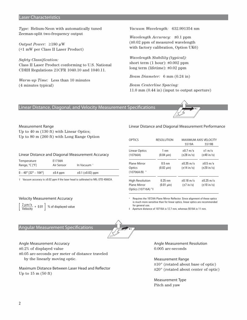
Measurement RangeUp to 40 m (130 ft) with Linear Optics;Up to 80 m (260 ft) with Long Range Option
Linear Distance and Diagonal Measurement AccuracyTemperature E1738ARange, °C [°F] Air Sensor In Vacuum †
Velocity Measurement Accuracy
Linear Distance and Diagonal Measurement Performance
OPTICS RESOLUTION MAXIMUM AXIS VELOCITY
Linear Optics 1 nm ±0.7 m/s ±1 m/s
(10766A) (0.04 µin) (±28 in/s) (±40 in/s)
Plane Mirror 0.5 nm ±0.35 m/s ±0.5 m/s
Optics (0.02 µin) (±14 in/s) (±20 in/s)
(10706A/B) *
High Resolution 0.25 nm ±0.18 m/s ±0.25 m/s
Plane Mirror (0.01 µin) (±7 in/s) (±10 in/s)
Optics (10716A) *‡
* Requires the 10724A Plane Mirror Reflector. Since alignment of these optics
is much more sensitive than for linear optics, linear optics are recommended
for general use.
‡ Aperture distance of 10716A is 12.7 mm, whereas 5519A is 11 mm.
Angle Measurement Accuracy±0.2% of displayed value ±0.05 arc-seconds per meter of distance traveled
by the linearly moving optic.
Maximum Distance Between Laser Head and Reflector Up to 15 m (50 ft)
Linear Distance, Diagonal, and Velocity Measurement Specifications
Y
X
Angular Measurement Specifications
Y
X
0 – 40° [32° – 104°] ±0.4 ppm ±0.1 (±0.02) ppm
† Vacuum accuracy is ±0.02 ppm if the laser head is calibrated to MIL-STD 45662A.
Angle Measurement Resolution0.005 arc-seconds
Measurement Range±10° (rotated about base of optic) ±20° (rotated about center of optic)
Type: Helium-Neon with automatically tunedZeeman-split two-frequency output
Output Power: ≥180 µW (<1 mW per Class II Laser Product)
Beam Diameter: 6 mm (0.24 in)
Beam Centerline Spacing:11.0 mm (0.44 in) (input to output aperture)
Safety Classification:Class II Laser Product conforming to U.S. NationalCDRH Regulations 21CFR 1040.10 and 1040.11.
Warm-up Time: Less than 10 minutes (4 minutes typical)
Vacuum Wavelength: 632.991354 nm
Wavelength Accuracy: ±0.1 ppm (±0.02 ppm of measured wavelengthwith factory calibration, Option UK6)
Wavelength Stability (typical): short term (1 hour): ±0.002 ppmlong term (lifetime): ±0.02 ppm
Laser Characteristics
Measurement TypePitch and yaw
+ 0.01 % of displayed value]2 μm/s
Velocity]
5519A 5519B

3
Measurement TypeRotary and indexing tables or spindles
Indexing Mode (zero-reference measurement)Accuracy: 0.5 sec band +0.2% of displayed readingIndex Step Size: 1°Range: multiple rotations or partial arcs
Laser Measurement ModeAccuracy: 0.2% of displayed reading. Accuracy can
be improved to 0.5 sec by calibrating laseroptics with the indexing table (55290A).
Range: ±10°
Setup RequirementsTravel (using +2 mm, –1 mm machine axis, or manual from zero reference)
Indexing Mode (Interferometer in fixture)Maximum Lift: 15 mm (2 mm required for fixture)
1. Values do not include effects of surface cleanliness or operator positioning repeatability.
Angular Position Measurement Specifications 0270
90
180
55290A Rotary Axis Kit
Flatness Measurement Accuracy ±0.2% of displayed value ±0.05 arc-seconds per meter of distance traveled by the moving optic
Flatness Measurement Resolution (per step)Footspacing Dimension Resolution
50.8 mm (2 in) 0.03 micron (1.0 µin)
101.6 mm (4 in) 0.05 micron (2.0 µin)
152.4 mm (6 in) 0.08 micron (3.0 µin)
Measurement TypeRotary and indexing tables or spindles
Combined Mode (zero-reference measurement)Accuracy: ±1.0 arc-secondResolution: 0.36 arc-secondsRange: multiple rotations or partial arcs
Laser Measurement ModeAccuracy: 0.2% of displayed reading. Accuracy can
be improved to 1 sec by calibrating laseroptics with the indexing table (55290B).
Range: ±10°
Setup RequirementsTravel – none required Connects to 5530 system via E1735A Axis Module
55290B Rotary Axis Kit
Flatness and Way Straightness Measurement Specifications
AH
G
B
F
CD
E
1
±0.2% of displayed value ±0.05 arc seconds per meter of
distance traveled by the moving optics
Way Straightness Accuracy
English Units Mode: 0.12 (F) 2 µin where: M = length of the surface diagonal in meters F = length of the surface diagonal in feet
Lateral Offset and Flatness Range The combination of lateral offset and maximumflatness deviation must not displace the reflectormore than ±1.0 mm from the beam path in anydirection.
Metric Units Mode: 0.03 (M) 2 µm
Reference Plane AccuracyThe uncertainty of a surface plate flatness measure-ment is bounded by two parallel planes separatedby the values below:
Flatness and Way Straightness Maximum Range 15m (50 ft)
4
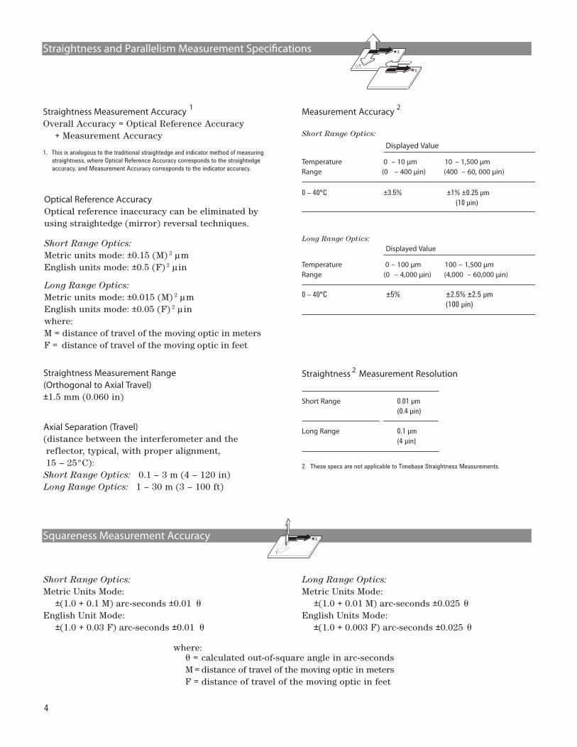
Short Range Optics:Metric Units Mode:
±(1.0 + 0.1 M) arc-seconds ±0.01 English Unit Mode:
±(1.0 + 0.03 F) arc-seconds ±0.01
Long Range Optics:Metric Units Mode:
±(1.0 + 0.01 M) arc-seconds ±0.025 English Units Mode:
±(1.0 + 0.003 F) arc-seconds ±0.025
where:= calculated out-of-square angle in arc-seconds
M = distance of travel of the moving optic in metersF = distance of travel of the moving optic in feet
Straightness and Parallelism Measurement SpecificationsY
X
X
Optical Reference AccuracyOptical reference inaccuracy can be eliminated byusing straightedge (mirror) reversal techniques.
Short Range Optics:Metric units mode: ±0.15 (M) 2 µmEnglish units mode: ±0.5 (F) 2 µin
Long Range Optics:Metric units mode: ±0.015 (M) 2 µmEnglish units mode: ±0.05 (F) 2 µinwhere:M = distance of travel of the moving optic in metersF = distance of travel of the moving optic in feet
Straightness Measurement Accuracy 1
Overall Accuracy = Optical Reference Accuracy + Measurement Accuracy
1. This is analogous to the traditional straightedge and indicator method of measuring
straightness, where Optical Reference Accuracy corresponds to the straightedge
accuracy, and Measurement Accuracy corresponds to the indicator accuracy.
Straightness Measurement Range (Orthogonal to Axial Travel)±1.5 mm (0.060 in)
Axial Separation (Travel)(distance between the interferometer and the reflector, typical, with proper alignment, 15 – 25°C):Short Range Optics: 0.1 – 3 m (4 – 120 in)Long Range Optics: 1 – 30 m (3 – 100 ft)
Measurement Accuracy
Short Range Optics:
Displayed Value
Temperature 0 – 10 μm 10 – 1,500 μmRange (0 – 400 μin) (400 – 60, 000 μin)
Long Range Optics:Displayed Value
Temperature 0 – 100 μm 100 – 1,500 μmRange (0 – 4,000 μin) (4,000 – 60,000 μin)
0 – 40°C ±5% ±2.5% ±2.5 µm
(100 µin)
Straightness Measurement Resolution
Short Range 0.01 µm
(0.4 µin)
Long Range 0.1 µm
(4 µin)
2
2
2. These specs are not applicable to Timebase Straightness Measurements.
0 – 40°C ±3.5% ±1% ±0.25 µm
(10 µin)
Squareness Measurement AccuracyY
X

5
Wavelength of Light (WOL) in Air Compensation The E1738A Air Sensor provides for the automaticdisplay of pressure, temperature, relative humidity,and computed WOL.
E1739A—5 m (16 ft)E1739B—10 m (33 ft)E1739C—15 m (49 ft)
Environmental Compensation and A-quad-B Input
E1738A Air Sensor
1. Compensation values may be manually entered by user via keyboard.
1
Maximum Compensation Update Rate per 15s (combined WOL and material temperaturecompensation)
Material Temperature Compensation The E1737A Material Temperature Sensor providesfor the automatic display of the temperature of thedevice under test. One to three sensors may be used.
Shared Sensor Characteristics
Cable Lengths:
E1739D—25 m (82 ft)
Operating RangeTemperature: 0 – 40°C (32 – 104°F)
Time Constant: 60s typical
Material Expansion Coefficient:range: –100.0 to +100.0 ppm per °C or °F, manually entered.
Heat Dissipation: 1 mW typical
Operating Range
Relative Humidity: 10% – 90%
Absolute Pressure: 70 – 110 kPa (10 – 16 psia)
Heat Dissipation: 2 mW typical
Time Constant: 5 min typical (temperature)
Temperature: 0 – 40°C (32 – 104°F)
2 E1737A Material Temperature Sensor 3
2. Refer to the E1738A Air Sensor Data Sheet, 5989-8456 for more specifications. 3. Refer to the E1737A Material Sensor Data Sheet, 5989-8455 for more specifications.
A-quad-B Input
Differential Input Threshold±0.5 V minimum, ±7.0 V maximum
Differential Input Impedance100Ω
Input Rate>2 μs edge-to-edge, or <500 kHz information rateexample: at maximum speed, A and B both mustbe <125 kHz.
Accuracy
Relative Humidity: ± 5%
Absolute Pressure: ± 50 Pa (± 0.001 psi)
Temperature: ± 0.1°C (± 0.2°F)
4
4. 12 month calibration interval
AccuracyTemperature: ± 0.1°C (± 0.2°F)
4
4. 12 month calibration interval
6
Laser Head and Tripod
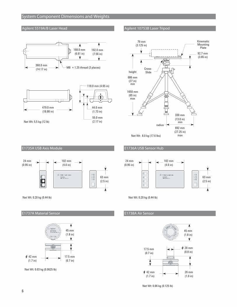
E1735A USB Axis Module E1736A USB Sensor Hub
Net Wt: 0.20 kg (0.44 lb) Net Wt: 0.20 kg (0.44 lb)
63 mm
(2.5 in)
102 mm
(4.0 in)
24 mm
(0.95 in)
63 mm
(2.5 in)
102 mm
(4.0 in)
24 mm
(0.95 in)
E1737A Material Sensor E1738A Air Sensor
Net Wt: 0.03 kg (0.0625 lb)
Net Wt: 0.06 kg (0.125 lb)
26 mm
(1.0 in)(1.7 in)
42 mmo
17.5 mm
(0.7 in) (0.8 in)
20 mmo
92.7 mm
(3.65 in)
height
686 mm
(27 in)
1650 mm
(65 in)max
Net Wt: 8.0 kg (17.6 lbs)
Cross-
Slide
radius
479.0 mm
(18.86 in)
Net Wt: 5.5 kg (12 lb)
44.0 mm
(1.73 in)
118.0 mm (4.65 in)
55.0 mm
(2.17 in)
168.0 mm
(6.61 in)
192.0 mm
(7.56 in)
360.0 mm
(14.17 in)M8 × 1.25 thread (3 places)
KinematicMounting
Plate
79 mm
(3.125 in)
min
min
330 mm
(13.0 in)
692 mm
max(27.25 in)
45 mm
(1.8 in)
17.5 mm
(0.7 in)(1.7 in)
42 mmo
45 mm
(1.8 in)
System Component Dimensions and Weights
Agilent 5519A/B Laser Head Agilent 10753B Laser Tripod
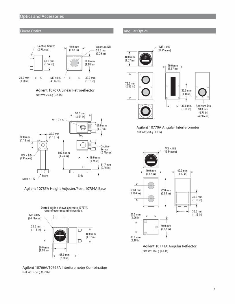
Optics and Accessories
Linear Optics Angular Optics
Net Wt: 5.36 g (1.2 lb)
107.8 mm(4.24 in)
90.0 mm(3.54 in)
CaptiveScrew(2 Places)
30.0 mm(1.18 in)
50.0 mm(1.97 in)
11.7 mm(0.46 in)
30.0 mm(1.18 in)
M10 1.5
M3 0.5(4 Places)
Front Side
19.0 mm(0.75 in)
Top
M10 × 1.5
×
×
7
Agilent 10785A Height Adjuster/Post, 10784A Base
Agilent 10766A/10767A Interferometer Combination
Agilent 10767A Linear Retroreflector
30.0 mm(1.18 in)
M3 × 0.5(4 Places)
40.0 mm(1.57 in)
40.0 mm(1.57 in)
25.0 mm(0.98 in)
Aperture Dia
20.0 mm(0.79 in)
Captive Screw
(2 Places)
30.0 mm(1.18 in)
Net Wt: 224 g (0.5 lb)
Agilent 10770A Angular InterferometerNet Wt: 553 g (1.3 lb)
M3 × 0.5(24 Places)
40.0 mm(1.57 in)
Aperture Dia18.0 mm (0.71 in)
(4 Places)
30.0 mm(1.18 in)
30.0 mm(1.18 in)
72.6 mm(2.86 in)
1 A 0 1 0 1
1077
0AAN
GULAR INTERFEROM
ET
ER
40.0 mm(1.57 in)
Agilent 10771A Angular Reflector30.0 mm(1.18 in)
M3 × 0.5(24 Places)
40.0 mm(1.57 in)
65.0 mm(2.56 in)
30.0 mm(1.18 in)
Dotted outline shows alternate 10767Aretroreflector mounting position.
1076
6ALIN
EAR INTERFEROME
T ER
Net Wt: 650 g (1.5 lb)
0.5
30.0 mm(1.18 in)
30.0 mm(1.18 in)27.0 mm
(1.06 in)
72.6 mm(2.86 in)
32.61 mm(1.284 in)
30.0 mm(1.18 in)
40.0 mm(1.57 in)
40.0 mm(1.57 in)
× M3(19 Places)
1 A 0 1 0 1
107
71A
ANGULAR REFLECTO
R
40.0 mm(1.57 in)
Optics and Accessories
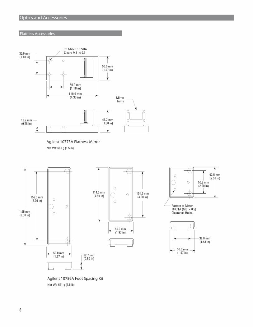
Flatness Accessories
8
1.65 mm(6.50 in)
152.5 mm(6.00 in)
114.3 mm(4.50 in)
101.6 mm(4.00 in)
Pattern to Match10771A (M3 × 0.5)Clearance Holes
50.0 mm(1.97 in) 12.7 mm
(0.50 in)
39.0 mm(1.53 in)
50.0 mm(1.97 in)
50.0 mm(1.97 in)
50.8 mm(2.00 in)
63.5 mm(2.50 in)
Agilent 10759A Foot Spacing KitNet Wt: 661 g (1.5 lb)
Agilent 10773A Flatness Mirror
MirrorTurns
Net Wt: 661 g (1.5 lb)
45.7 mm(1.80 in)
12.2 mm(0.48 in)
30.0 mm(1.18 in)
30.0 mm(1.18 in)
50.0 mm(1.97 in)
110.0 mm(4.33 in)
Clears M3 To Match 10770A
× 0.5
Optics and Accessories
Straightness / Squareness Optics
9
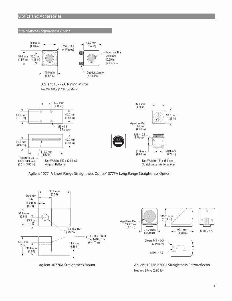
Agilent 10772A Tuning Mirror
Agilent 10774A Short Range Straightness Optics/10775A Long Range Straightness Optics
Agilent 10776A Straightness Mount Agilent 10776-67001 Straightness Retroreflector
M3 × 0.5
(4 Places)
40.0 mm(1.57 in)
40.0 mm(1.57 in)
Aperture Dia
20.0 mm
(0.79 in)
(2 Places)
Captive Screw(2 Places)
30.0 mm(1.18 in)
40.0 mm(1.57 in)
30.0 mm(1.18 in)
Net Wt: 510 g (1.2 lb) w/Mount
M3 × 0.5(16 Places)
30.0 mm(1.18 in)
30.0 mm(1.18 in)
25.0 mm(0.98 in)
110.0 mm(4.33 in)
Net Weight: 800 g (28.2 oz)
Angular Reflector
40.0 mm(1.57 in)
Aperture Dia8.0 98.0 mm(0.31× 3.66 in)
×
Aperture Dia7.9 mm(0.31 in)
20.0 mm(0.79 in)
32.0 mm(1.26 in)
21.0 mm(0.83 in)
M3 0.5(2 Places)
Net Weight: 164 g (5.8 oz)
Straightness Interferometer
1 A 0 1 0 1
1077
5A
ANGULAR REFLECTO
R
32.0 mm(1.26 in)
×
M10 1.5
Clears M3 0.5(2 Places)
86.2 mm(3.39 in)
M10 1.5
Aperture Dia63.5 mm
(2.5 in)99.1 mm(3.90 in)
76.2 mm(3.00 in)
Net Wt: 374 g (0.82 lb)
×
×
×
90.0 mm(3.54)
51.0 mm(2.01)
25.5 mm(1.00)
11.7 mm(0.46 in)
19.1 Dia Thru(.75 Dia)
36.0 mm(1.42)
18.0 mm(0.71)
55.0 mm(2.17)
38.0 mm(1.50)
11.0 Dia C'SinkTap M10 x 1.5(6H) Thru
40.0 mm(1.57 in)
10
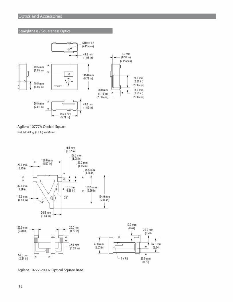
Net Wt: 4.0 kg (8.9 lb) w/Mount
Agilent 10777A Optical Square
Agilent 10777-20007 Optical Square Base
M10 x 1.5(4 Places)
145.0 mm(5.71 in)
49.5 mm(1.95 in)
43.0 mm(1.69 in)
71.0 mm(2.80 in)
(2 Places)
49.5 mm(1.95 in)
49.5 mm(1.95 in)
14.0 mm(0.55 in)
(2 Places)
8.0 mm(0.31 in)
(2 Places)
28.0 mm
(1.10 in)(2 Places)
145.0 mm(5.71 in)
50.9 mm(2.01 in)
OPTICAL SQUARE10777A
Optics and Accessories
Straightness / Squareness Optics
67.0 mm(2.64)
12.0 mm(0.47)
77.0 mm(3.03 in)
20.0 mm(0.70)
20.0 mm(0.70)
4 x R5
20.0 mm(0.70 in)
20.0 mm(0.70 in)
32.0 mm(1.26 in)
59.5 mm(2.34 in)
139.6 mm(5.50 in)
32.0 mm(1.26 in)
20.0 mm(0.79 in)
15.0 mm(0.59 in)
34°
75.5 mm(1.26 in)
29.3 mm(1.15 in)
27.5 mm(1.08 in)
9.5 mm(0.37 in)
154.0 mm(6.06 in)
15.0 mm
36.5 mm(1.44 in)
25°
133.5 mm(5.26 in)(0.59 in)
11
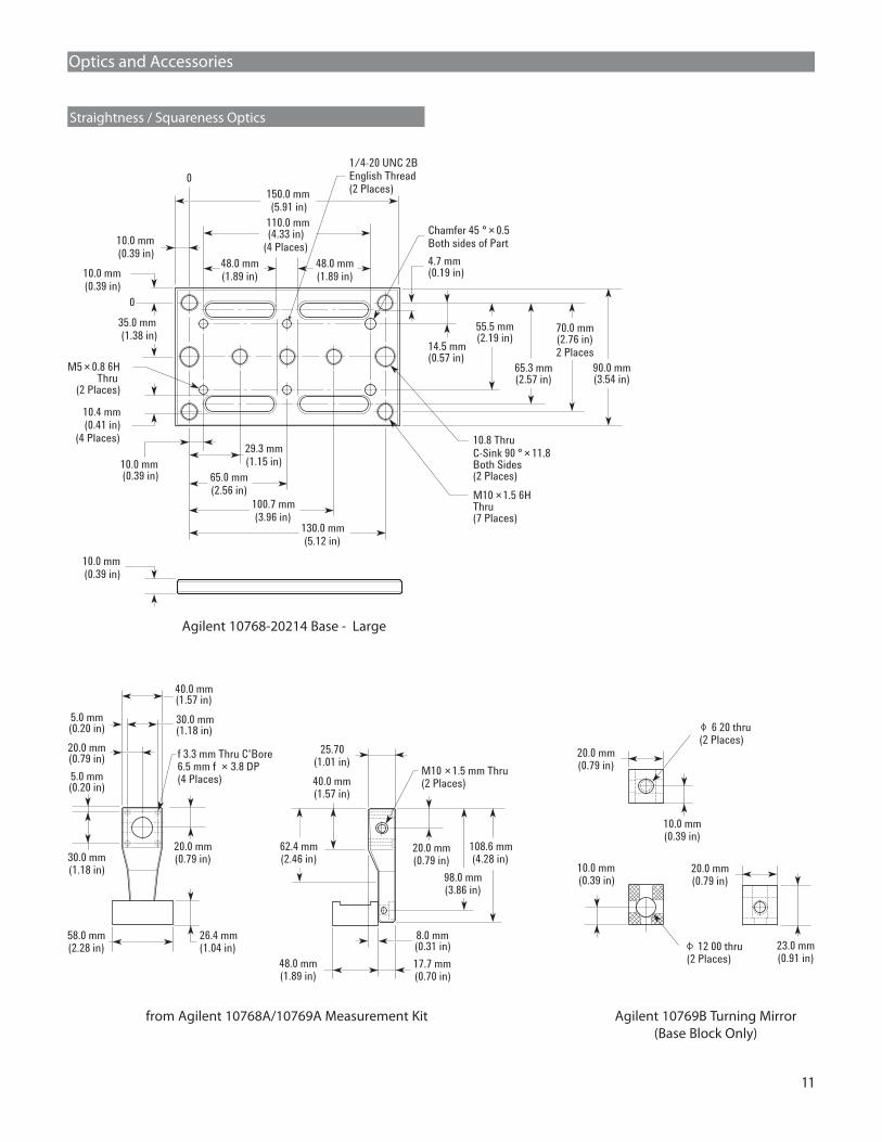
Agilent 10768-20214 Base - Large
from Agilent 10768A/10769A Measurement Kit
10.0 mm(0.39 in)
29.3 mm
(1.15 in)
35.0 mm
(1.38 in)
65.0 mm
(2.56 in)
100.7 mm
(3.96 in)130.0 mm
(5.12 in)
0
10.0 mm
(0.39 in)
10.4 mm
(0.41 in)
(4 Places)
110.0 mm(4.33 in)
(4 Places)
48.0 mm
(1.89 in)
10.0 mm
(0.39 in)
0
4.7 mm(0.19 in)
14.5 mm(0.57 in)
Chamfer 45 ° × 0.5
Both sides of Part
1/4-20 UNC 2B
English Thread
(2 Places)
M5 × 0.8 6HThru
(2 Places)
10.8 Thru
C-Sink 90 ° × 11.8Both Sides(2 Places)
M10 × 1.5 6HThru(7 Places)
10.0 mm
(0.39 in)
65.3 mm(2.57 in)
70.0 mm(2.76 in)
2 Places
90.0 mm(3.54 in)
55.5 mm(2.19 in)
48.0 mm
(1.89 in)
150.0 mm
(5.91 in)
(1.57 in)
58.0 mm(2.28 in)
26.4 mm(1.04 in)
20.0 mm(0.79 in)
20.0 mm(0.79 in)
30.0 mm(1.18 in)
5.0 mm(0.20 in)
(0.20 in)
30.0 mm(1.18 in)
f 3.3 mm Thru C'Bore6.5 mm f × 3.8 DP(4 Places)
40.0 mm
5.0 mm 40.0 mm(1.57 in)
108.6 mm(4.28 in)
8.0 mm(0.31 in)
17.7 mm(0.70 in)
48.0 mm(1.89 in)
25.70(1.01 in)
M10 × 1.5 mm Thru(2 Places)
20.0 mm(0.79 in)
98.0 mm(3.86 in)
62.4 mm(2.46 in)
Optics and Accessories
Straightness / Squareness Optics
Agilent 10769B Turning Mirror(Base Block Only)
23.0 mm(0.91 in)
20.0 mm(0.79 in)
10.0 mm(0.39 in)
10.0 mm(0.39 in)
20.0 mm(0.79 in)
(2 Places)
(2 Places)
6 20 thru
12 00 thru
12
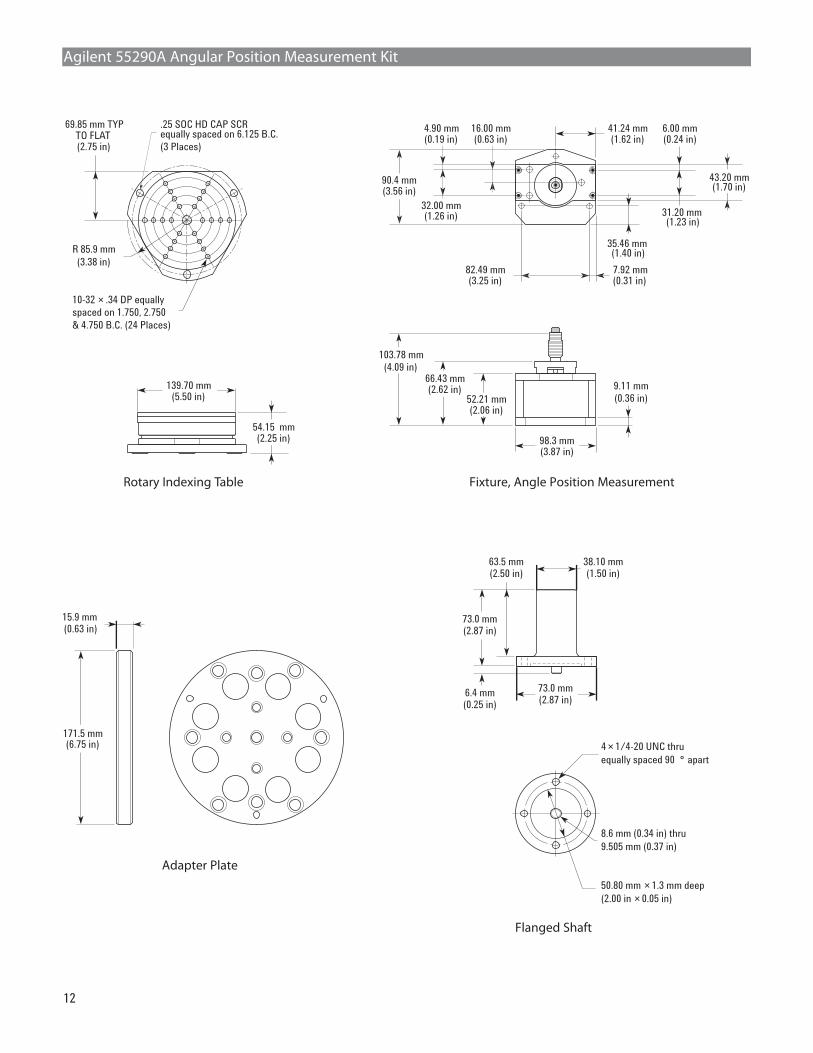
6.4 mm(0.25 in)
63.5 mm(2.50 in)
73.0 mm(2.87 in)
73.0 mm(2.87 in)
50.80 mm × 1.3 mm deep
(2.00 in × 0.05 in)
4 × 1/4-20 UNC thru
equally spaced 90 ° apart
38.10 mm(1.50 in)
8.6 mm (0.34 in) thru
9.505 mm (0.37 in)
Flanged Shaft
Agilent 55290A Angular Position Measurement Kit
Fixture, Angle Position Measurement
103.78 mm
(4.09 in)
52.21 mm(2.06 in)
66.43 mm(2.62 in) 9.11 mm
(0.36 in)
98.3 mm(3.87 in)
82.49 mm(3.25 in)
7.92 mm(0.31 in)
90.4 mm(3.56 in)
43.20 mm(1.70 in)
32.00 mm(1.26 in)
4.90 mm(0.19 in)
16.00 mm(0.63 in)
41.24 mm(1.62 in)
35.46 mm(1.40 in)
31.20 mm(1.23 in)
6.00 mm(0.24 in)
Rotary Indexing Table
54.15 mm(2.25 in)
139.70 mm(5.50 in)
69.85 mm TYPTO FLAT(2.75 in)
.25 SOC HD CAP SCRequally spaced on 6.125 B.C.
(3 Places)
10-32 × .34 DP equally
spaced on 1.750, 2.750
& 4.750 B.C. (24 Places)
R 85.9 mm
(3.38 in)
Adapter Plate
171.5 mm(6.75 in)
15.9 mm(0.63 in)
13
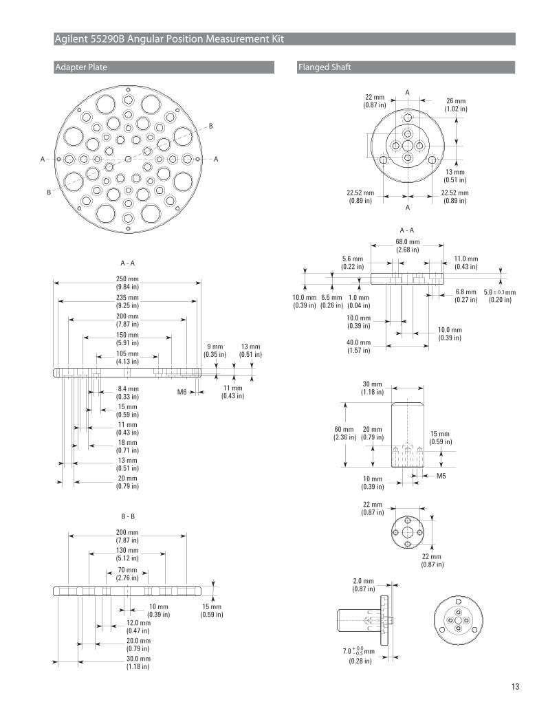
235 mm(9.25 in)
250 mm(9.84 in)
200 mm(7.87 in)
150 mm(5.91 in)
105 mm(4.13 in)
200 mm(7.87 in)
130 mm(5.12 in)
70 mm(2.76 in)
A - A
22.52 mm(0.89 in)
22.52 mm(0.89 in)
22 mm(0.87 in)
26 mm(1.02 in)
13 mm(0.51 in)
A
A
AA
B
B
B - B
9 mm(0.35 in)
11 mm(0.43 in)
13 mm(0.51 in)
M6
15 mm(0.59 in)
8.4 mm(0.33 in)
11 mm(0.43 in)
18 mm(0.71 in)
13 mm(0.51 in)
20 mm(0.79 in)
15 mm(0.59 in)
12.0 mm(0.47 in)
10 mm(0.39 in)
20.0 mm(0.79 in)
30.0 mm(1.18 in)
22 mm(0.87 in)
22 mm(0.87 in)
Agilent 55290B Angular Position Measurement Kit
Adapter Plate Flanged Shaft
A - A
30 mm(1.18 in)
15 mm(0.59 in)
60 mm(2.36 in)
20 mm(0.79 in)
10 mm(0.39 in)
M5
68.0 mm(2.68 in)
11.0 mm(0.43 in)
5.6 mm(0.22 in)
40.0 mm(1.57 in)
10.0 mm(0.39 in)
10.0 mm(0.39 in)
6.8 mm(0.27 in)1.0 mm
(0.04 in)6.5 mm(0.26 in)
10.0 mm(0.39 in)
(0.20 in) 5.0 mm± 0.3
2.0 mm(0.87 in)
(0.28 in)
7.0 mm+ 0.0- 0.5

Agilent Technologies’ Test and MeasurementSupport, Services, and AssistanceAgilent Technologies aims to maximize the value
you receive, while minimizing your risk and prob-
lems. We strive to ensure that you get the test
and measurement capabilities you paid for and
obtain the support you need. Our extensive sup-
port resources and services can help you choose
the right Agilent products for your applications
and apply them successfully. Every instrument
and system we sell has a global warranty.
Support is available for at least five years beyond
the production life of the product. Two concepts
underlie Agilent’s overall support policy: “Our
Promise” and “Your Advantage.”
Our PromiseOur Promise means your Agilent test and mea-
surement equipment will meet its advertised
performance and functionality. When you are
choosing new equipment, we will help you with
product information, including realistic perfor-
mance specifications and practical recommenda-
tions from experienced test engineers. When you
receive your new Agilent equipment, we can help
verify that it works properly and help with initial
product operation.
Your AdvantageYour Advantage means that Agilent offers
a wide range of additional expert test and
measurement services, which you can purchase
according to your unique technical and business
needs. Solve problems efficiently and gain a
competitive edge by contracting with us for
calibration, extra-cost upgrades, out-of-warranty
repairs, and onsite education and training, as well
as design, system integration, project management,
and other professional engineering services.
Experienced Agilent engineers and technicians
worldwide can help you maximize your productivity,
optimize the return on investment of your Agilent
instruments and systems, and obtain dependable
measurement accuracy for the life of those products.
www.agilent.com/find/emailupdatesGet the latest information on the products and
applications you select.
Agilent T&M Software and ConnectivityAgilent’s Test and Measurement software and
connectivity products, solutions and developer
network allows you to take time out of connect-
ing your instruments to your computer with tools
based on PC standards, so you can focus on your
tasks, not on your connections. Visit
www.agilent.com/find/connectivityfor more information.
For more information on AgilentTechnologies’ products, applications orservices, please contact your local Agilentoffice. The complete list is available at:www.agilent.com/find/contactus
Agilent Email Updates
Phone or Fax
United States:(tel) 800 829 4444
(fax) 800 829 4433
Canada:(tel) 877 894 4414
(fax) 905 282 6495
China:(tel) 800 810 0189
(fax) 800 820 2816
Europe:(tel) 31 20 547 2111
Japan:(tel) (81) 426 56 7832
(fax) (81) 426 56 7840
Korea:(tel) (080) 769 0800
(fax) (080)769 0900
Latin America:(tel) (305) 269 7500
Taiwan:
(tel) 0800 047 866
(fax) 0800 286 331
Other Asia Pacific Countries:(tel) (65) 6375 8100
(fax) (65) 6755 0042
Email: [email protected]
Product specifications and descriptions
in this document subject to change
without notice.
© Agilent Technologies, Inc. 2008
Printed in USA, November 13, 2008
5989-9712EN
More information about AgilentTechnologies’ laser interferometric dynamic calbrators is available at:www.agilent.com/find/machinetoolcalibration