Embed Size (px)
Citation preview

Developed by ACI Committee E-701
ACI Education Bulletin E1-07
Aggregates for Concrete

American Concrete Institute®
Advancing concrete knowledge
Aggregates for Concrete
First PrintingAugust 2007
ISBN 978-0-87031-248-9
Copyright by the American Concrete Institute, Farmington Hills, MI. All rights reserved. This materialmay not be reproduced or copied, in whole or part, in any printed, mechanical, electronic, film, or otherdistribution and storage media, without the written consent of ACI.
The technical committees responsible for ACI committee reports and standards strive to avoid ambiguities,omissions, and errors in these documents. In spite of these efforts, the users of ACI documents occa-sionally find information or requirements that may be subject to more than one interpretation or may beincomplete or incorrect. Users who have suggestions for the improvement of ACI documents arerequested to contact ACI.
ACI committee documents are intended for the use of individuals who are competent to evaluate thesignificance and limitations of its content and recommendations and who will accept responsibility for theapplication of the material it contains. Individuals who use this publication in any way assume all risk andaccept total responsibility for the application and use of this information.
All information in this publication is provided “as is” without warranty of any kind, either express or implied,including but not limited to, the implied warranties of merchantability, fitness for a particular purpose ornon-infringement.
ACI and its members disclaim liability for damages of any kind, including any special, indirect, incidental,or consequential damages, including without limitation, lost revenues or lost profits, which may resultfrom the use of this publication.
It is the responsibility of the user of this document to establish health and safety practices appropriate tothe specific circumstances involved with its use. ACI does not make any representations with regard tohealth and safety issues and the use of this document. The user must determine the applicability of allregulatory limitations before applying the document and must comply with all applicable laws and regula-tions, including but not limited to, United States Occupational Safety and Health Administration (OSHA)health and safety standards.
Order information: ACI documents are available in print, by download, on CD-ROM, through electronicsubscription, or reprint and may be obtained by contacting ACI.
Most ACI standards and committee reports are gathered together in the annually revised ACI Manual ofConcrete Practice (MCP).
American Concrete Institute38800 Country Club DriveFarmington Hills, MI 48331U.S.A.Phone: 248-848-3700Fax: 248-848-3701
www.concrete.org

E1-1
ACI Education Bulletin E1-07. Supersedes E1-99.Copyright © 2007. American Concrete Institute.All rights reserved including rights of reproduction and use in any form or by any
means, including the making of copies by any photo process, or by electronic ormechanical device, printed, written, or oral, or recording for sound or visual reproductionor for use in any knowledge or retrieval system or device, unless permission in writing isobtained from the copyright proprietors. Printed in the United States of America.
The Institute is not responsible for the statements oropinions expressed in its publications. Institute publicationsare not able to, nor intended to, supplant individualtraining, responsibility, or judgment of the user, or thesupplier, of the information presented.
CONTENTS
Chapter 1—Introduction, p. E1-2
Chapter 2—Classification of aggregates, p. E1-2
Chapter 3—Aggregate properties and test methods, p. E1-23.1—Grading
3.1.1—Definition and test method3.1.2—Fineness modulus3.1.3—Maximum size and nominal maximum size3.1.4—Significance of aggregate grading 3.1.5—Permissible variations in grading
3.2—Specific gravity (relative density)3.2.1—Definition3.2.2—Determination of specific gravity3.2.3—Significance of specific gravity3.2.4—Absolute volume calculations
3.3—Absorption and surface moisture3.3.1—Mixing water and water-cementitious material
ratio3.3.2—Absorption and total moisture content3.3.3—Surface moisture content3.3.4—Computing mixing water and water-cementitious
material ratio3.3.5—Adjusting batch masses for surface moisture3.3.6—Alternate definition of surface moisture
3.4—Bulk density (replaces de-emphasized term “unit weight”)3.4.1—Definition and test method3.4.2—Factors affecting bulk density
3.5—Particle shape, angularity, and surface texture3.5.1—Definition3.5.2—Test methods3.5.3—Significance of particle shape and surface texture
3.6—Abrasion and impact resistance3.6.1—Definition and significance3.6.2—Test method
3.7—Soundness3.7.1—Definition and mechanism of deterioration3.7.2—Test methods3.7.3—Pop-outs
3.8—Chemical stability3.8.1—Definition and reaction mechanisms3.8.2—Test methods3.8.3—Corrective measures
3.9—Harmful substances in aggregates3.9.1—Types of harmful substances3.9.2—Effects of harmful substances3.9.3—Test methods
Chapter 4—Sampling aggregates, p. E1-204.1—Variability in aggregates4.2—Sampling
4.2.1—Definition4.2.2—Significance of variability
AGGREGATES FOR CONCRETE
ACI Education Bulletin E1-07
Leonard W. Bell Morris S. Huffman Kenneth Rear
Richard Bohan Colin Lobo Jere H. Rose
David Burg Stella L. Marusin Paul J. Tikalsky
Darrell Elliot Ibrahim Metwally Kari Yuers
James A. Farny Charles Nmai Robert Zellers
Jose P. Garcia Anthony C. Powers
Note: Special credit is extended to Ward R. Malisch, who developed the first edition and made aneditorial contribution to this edition.
Developed by Committee E-701,Materials for Concrete Construction
David M. Suchorski,Chair

E1-2 ACI EDUCATION BULLETIN
4.2.3—Sampling plans4.2.4—Sampling methods4.2.5—Number and size of field samples 4.2.6—Sample containers
Chapter 5—Blast-furnace slag aggregates, p. E1-215.1—Blast-furnace slag
5.1.1—Definition5.1.2—Properties5.1.3—Availability
Chapter 6—Lightweight aggregates, p. E1-216.1—Introduction to lightweight aggregates6.2—Definition of lightweight-aggregate concrete6.3—Low-density concretes and associated aggregates
6.3.1—Structural lightweight concrete and associatedaggregates
6.3.2—Moderate-strength lightweight concrete andassociated aggregates
6.3.3—Properties
Chapter 7—Recycled aggregates, p. E1-237.1—Introduction to recycled aggregates
7.1.1—Definition7.1.2—Properties
Chapter 8—Selected references on aggregates,p. E1-24
Chapter 9—Glossary, p. E1-25
CHAPTER 1—INTRODUCTIONHydraulic cement concrete is a cement and water paste in
which aggregate particles are embedded. Aggregate is granularmaterial such as sand, gravel, crushed stone, blast-furnaceslag, and lightweight aggregates that usually occupies approxi-mately 60 to 75% of the volume of concrete. Aggregateproperties significantly affect the workability of plasticconcrete and also the durability, strength, thermal properties,and density of hardened concrete.
This Bulletin describes types of aggregates normally usedin concrete, aggregate properties affecting performance ofthe concrete, tests used to measure aggregate properties, andmethods used to obtain test samples. Normalweight as wellas lightweight aggregates are discussed.
The measurement system used in this Bulletin is the Inter-national System of Units, or SI Units. Accordingly, readersshould make particular note that the term “weight” has beenreplaced with “mass,” and “unit weight” has been replacedwith “density” when used in reference to the absolute volumeaggregates occupy in concrete, and with “bulk density”when used in reference to aggregates, such as the mass perunit volume of a collection of graded aggregate particles ascompacted in a volumetric bucket or the relation of mass tovolume of aggregates in a stockpile or bin. As a convenience,most of the examples provided in the Bulletin are in both SIand U.S. customary (in.-lb) units.
Frequent references are made to ASTM International(ASTM) standards. These include test methods, definitions,
recommended practices, classifications, and specificationsthat have been formally adopted by ASTM. New editions ofthe ASTM Book of Standards are issued annually, and allreferences to these standards in this Bulletin refer to the mostrecent edition. Organizations such as ACI and others havesimilar or additional standards that may be applicable.
CHAPTER 2—CLASSIFICATION OF AGGREGATESAggregates may be broadly classified as natural or artificial,
both with respect to source and to method of preparation.Natural sands and gravels are the product of weathering andthe action of wind or water, while manufactured crushed fineaggregate and crushed stone coarse and fine aggregate areproduced by crushing natural stone. Crushing, screening,and washing may be used to process aggregates from eithersand and gravel deposits or stone quarries. Aggregatesmay be produced from igneous, sedimentary, or metamorphicrocks, but geological type does not by itself make an aggregatesuitable or unsuitable for use in concrete. The acceptance ofan aggregate for use in concrete on a particular job or inmeeting a particular specification should be based upon specificinformation obtained from tests used to measure the aggregate’squality or, more importantly, its service record, or both.More performance tests are also used to test aggregates inconcrete. A typical consensus specification for fine and coarseaggregate for concrete is ASTM C 33.
Synthetic aggregates may be either byproducts of an industrialprocess, in the case of blast-furnace slag, or products ofprocesses developed to manufacture aggregates with specialproperties, as in the case of expanded clay, shale, or slateused for lightweight aggregates. Some lightweight aggregatessuch as pumice or scoria also occur naturally.
Other classifications of aggregates may be based on bulkdensity, (previously termed “unit weight”) (ASTM C 33, C 330,and C 637), mineralogical composition (ASTM C 294), andparticle shape, but these, as well as the ones previouslydiscussed, serve mainly as aids in describing an aggregate.To understand the role played by aggregate in the performanceof concrete, it is necessary to define specific aggregate propertiesand show their effect on concrete properties.
CHAPTER 3—AGGREGATE PROPERTIESAND TEST METHODS
3.1—Grading3.1.1 Definition and test method—Grading refers to the
distribution of particle sizes present in an aggregate. Thegrading is determined in accordance with ASTM C 136, “Sieveor Screen Analysis of Fine and Coarse Aggregates.” A sampleof the aggregate is shaken through a series of wire-clothsieves with square openings, nested one above the other inorder of size, with the sieve having the largest openings on top,the one having the smallest openings at the bottom, and a panunderneath to catch material passing the finest sieve (Fig. 1).Sieve sizes commonly used for concrete aggregates are detailedin Table 1, and various physical properties of normalweightaggregates, with typical range values, are shown in Table 2.
Coarse and fine aggregates are generally sieved separately.That portion of an aggregate passing the 4.75 mm (No. 4)

AGGREGATES FOR CONCRETE E1-3
sieve and predominantly retained on the 75 µm (No. 200)sieve is called “fine aggregate” or “sand,” and larger aggregateis called “coarse aggregate.” Coarse aggregate may be availablein several different size groups, such as 19 to 4.75 mm (3/4 in.to No. 4), or 37.5 to 19 mm (1-1/2 to 3/4 in.).
ASTM C 33 (“Standard Specifications for Concrete Aggre-gates”) lists several such size groups using the simplifiedpractice recommendation (SPR) number designation. Thenumber and size of sieves selected for a sieve analysis dependson the particle sizes present in the sample and the gradingrequirements specified.
After sieving, the mass of material retained on each sieveand in the pan is obtained using a balance accurate to 0.1%of the test-sample mass. Results are recorded in tabular formwith some or all of the following quantities retained on eachsieve, individual percent retained on each sieve (and passingthe sieve above), and total percent of the whole samplepassing each sieve. For an accurate determination of the
amount of material finer than the 75 µm (No. 200) sieve, aspecimen is washed in accordance with ASTM C 117. Thismay be done on the sieve analysis sample before sieving(with the results included in the sieve analysis) or it can bedone on a separate sample.
Grading charts are often used to show the results of a sieveanalysis graphically. The percent passing is usually plottedon the vertical axis, while the sieve sizes are plotted on thehorizontal axis. Upper and lower limits specified for theallowable percentage of material passing each sieve mayalso be included on the grading chart. Figure 2 shows atypical grading chart for coarse and fine aggregates havinggrading calculated in the following two examples. To eval-uate consistency of the grading the individual size fractionsof a coarse aggregate, fine aggregate (or the calculatedproposed combined aggregate grading in concrete) is some-times plotted separately to identify any gaps or excessamounts in particular sizes.
Table 1—Sieves commonly used for sieve analysis of concrete aggregates
Standard sieve designation (ASTM E 11)
Nominal sieve opening
mm in.
Coarse sieves
Standard Alternate
75.0 mm 3 in. 75.0 3
63.0 mm 2-1/2 in. 63.0 2.5
50.0 mm 2 in. 50.0 2
37.5 mm 1-1/2 in. 37.5 1.5
25.0 mm 1 in. 25.0 1
19.0 mm 3/4 in. 19.0 0.75
12.5 mm 1/2 in. 12.5 0.5
9.5 mm 3/8 in. 9.5 0.375
Fine sieves
4.75 mm No. 4 4.75 0.1870
2.36 mm No. 8 2.36 0.0937
1.18 mm No. 16 1.18 0.0469
600 μm* No. 30 0.60 0.0234
300 μm No. 50 0.30 0.0117
150 μm No. 100 0.15 0.0059
Finest sieve normally used for aggregates
75 μm No. 200 0.075 0.0029*1000 µm (micro-meters) = 1 mm.
Table 2—Ranges in physical properties for normal-weight aggregates used in concrete
Property Typical ranges
Fineness modulus of fine aggregate (defined in the following) 2.0 to 3.3
Nominal maximum size of coarse aggregate 9.5 to 37.5 mm(3/8 to 1-1/2 in.)
Absorption 0.5 to 4%
Bulk specific gravity (relative density) 2.30 to 2.90
Dry-rodded bulk density* of coarse aggregate1280 to 1920 kg/m3
(80 to 120 lb/ft3)
Surface moisture contentCoarse aggregate 0 to 2%
Fine aggregate 0 to 10%*Previously dry-rodded unit weight.
Fig. 1—Nest of sieves.
Fig. 2—Typical grading chart. Dashed lines indicate limitsspecified in ASTM C 33 for fine aggregates and for 25.0 mm(1 in.) coarse aggregate.

E1-4 ACI EDUCATION BULLETIN
Example 1: Calculations for sieve analysis of fine aggregateA sample of fine aggregate with a mass of 510.5 g is passed
through the sieves shown in the following and the massesretained on each sieve are as shown.
Note that the total of masses retained may differ slightlyfrom the original sample mass due to loss or gain in the sievingprocess or due to round-off error. Because the mass of materialon each sieve is determined to within 0.1% of the total samplemass, the maximum difference should not exceed 0.1% timesthe number of mass determinations. In this example, seven massdeterminations were made, so the difference should not exceed0.7%. The total of masses retained differs from the mass of theoriginal sample by 2 g, or only 0.4%. If the difference had beentoo great, a check would have been made for possible errors inmass determination, calculation, accidental loss due to spillage,or material stuck in the sieve openings. Normally, the sieveanalysis calculations are done to the nearest 0.1% and thenreported to the nearest 1%, except for the percent passingthe No. 200 sieve, which is reported to the nearest 0.1%
The total mass of the material after sieving should checkclosely with the original mass of the sample placed on thesieves. If the amounts differ by more than 0.3%, based on theoriginal dry sample mass, the results should not be used foracceptance purposes.
Individual percent retained is the percentage of materialcontained between successive sieves, recorded to the nearestwhole percent. It is calculated by dividing the mass retained oneach sieve (and passing the sieve above) by the sum of the massesretained on each sieve and the pan and multiplying by 100.
The total percent passing is calculated by subtracting thetotal (cumulative) percent retained from 100.
Example 2: Calculations for sieve analysis of coarseaggregate
A sample of coarse aggregate with a mass of 8145 g ispassed through the sieves and the masses retained on each sieveare as shown.
Sieve sizeMass retained, g,
individual on each sieveIndividual % retained
Total % retained
cumulativeTotal % passing
3/8 0.0 0.0 0 1004.75 mm (No. 4) 9.2 2 2 982.36 mm (No. 8) 67.6 13 15 851.18 mm (No. 16) 101.2 20 35 65600 μm (No. 30) 102.2 20 55 45300 μm (No. 50) 120.5 24 79 21150 μm (No. 100) 93.1 18 97 375 μm (No. 200) 10.2 2 99 1
Pan 4.5 1 100 0Total 508.5 100 — —
Sieve sizeMass
retained, gIndividual %
retainedTotal % retained
Total % passing
25.0 mm (1 in.) 0 0 0 10019.0 mm (3/4 in.) 405 5 5 9512.5 mm (1/2 in.) 2850 35 40 609.5 mm (3/8 in.) 2435 30 70 304.75 mm (No. 4) 2030 25 95 52.36 mm (No. 8) 375 5 100 0
Pan 35 0 100 0Total 8130 100 — —
Note again that the total of masses retained differs fromthe original sample mass. Six mass determinations weremade so the difference should not exceed 0.6% of the totalsample mass. The total of masses retained differs from theoriginal sample mass by 15 g or only 0.2%. See Example 1for steps to be taken if the difference had been too great. Allother calculations are carried out as in Example 1.
If the test sample was first tested by ASTM C 117, includethe mass of material finer than the 75 µm (No. 200) size thatwas obtained by washing in the sieve analysis calculation.Use the total dry sample mass before washing as the basis forcalculating all the percentages and include the mass of thepassing No. 200 in the calculation.
3.1.2 Fineness modulus—Using the sieve analysis results,a numerical index called the fineness modulus (FM) is oftencomputed. The FM is the sum of the total percentagescoarser than each of a specified series of sieves, divided by100. The specified sieves are 75.0, 37.5, 19.0, and 9.5 mm (3,1.5, 3/4, and 3/8 in.) and 4.75 mm, 2.36 mm, 1.18 mm, 600µm, 300 µm, and 150 µm (No. 4, 8, 16, 30, 50, and 100).Note that the lower limit of the specified series of sieves isthe 150 µm (No. 100) sieve and that the actual size of theopenings in each larger sieve is twice that of the sieve below.The coarser the aggregate, the higher the FM. For fine aggregateused in concrete, the FM generally ranges from 2.3 to 3.1 ascalled for in ASTM C 33, but in some cases, fine sands areused with an FM less than 2.0 (for example, some Floridadeposits) and in other cases, a coarser fine aggregate with anFM higher that 3.1 (for example, some western coarse sandsor manufactured fine aggregate that is used in concrete witha finer natural sand).
Example 3: Calculation of fineness modulus for fineaggregate
Given the following sieve analysis, determine the FM.
Note that all of the FM sieves below the maximum size(that has nothing retained, 3/8 in. in this case) must be included,and none of the non-FM sieves can be included. For example, ifa No. 200 or a 1/2 in. sieve were included in the sieve analysis,the cumulative percent retained on those sieves would notbe included in the FM calculation because they are not in theFM series.
Although the FM is most commonly computed for fineaggregates, the FM of coarse aggregate is needed for someproportioning methods. It is calculated in the same manner,while taking care to exclude sieves that are not specified in thedefinition (for example, 25.0 and 12.5 mm [l and 1/2 in.] sieves)and to include all of the specified finer sieves.
Sieve size Total % retained3/8 0
4.75 mm (No. 4) 22.36 mm (No. 8) 15
1.18 mm (No. 16) 35600 μm (No. 30) 55300 μm (No. 50) 79
150 μm (No. 100) 97Sum 283
Fineness modulus = 283/100 = 2.83

AGGREGATES FOR CONCRETE E1-5
Example 4: Calculation of fineness modulus for coarseaggregate
Given the following sieve analysis, determine the FM.
Even though the 25 and 12.5 mm (l and 1/2 in.) sieveswere used in the sieve analysis, they are not included in thecalculation. Because the total percent retained on the 2.36 mm(No. 8) sieve is 100%; 100% will also be retained on thesmaller sieves specified in the FM definition. Thus, thecalculation is as follows.
Example 5: Calculation of grading when two or moreaggregates are combined
Suppose that three aggregates are combined in the masspercentages indicated. For the given individual aggregategrading, determine the grading of the combined aggregate.
The combined grading is shown in the table that follows.The percent passing is calculated for each of the sieve sizesas follows. Example: Calculate the percent passing the 9.5 mm(3/8 in.) sieve of the combined blended aggregates. One-hundred percent of Aggregate 1 passes the 9.5 mm (3/8 in.)
Sieve size Total % retained25.0 mm (1 in.) 0
19.0 mm (3/4 in.) 512.5 mm (1/2 in.) 409.5 mm (3/8 in.) 704.75 mm (No. 4) 952.36 mm (No. 8) 100
Sieve size Total % retained19.0 mm (3/4 in.) 59.5 mm (3/8 in.) 704.75 mm (No. 4) 952.36 mm (No. 8) 100
1.18 mm (No. 16) 100600 μm (No. 30) 100300 μm (No. 50) 100150 μm (No. 100) 100
Sum 670Fineness modulus = 670/100 = 6.70
Sieve sizePercent passing
Aggregate 1 Aggregate 2 Aggregate 350 mm (2 in.) 100 100 100
37.5 mm (1-1/2 in.) 100 100 9525.0 mm (1 in.) 100 100 51
19.0 mm (3/4 in.) 100 100 2512.5 mm (1/2 in.) 100 99 89.5 mm (3/8 in.) 100 89 24.75 mm (No. 4) 99 24 02.36 mm (No. 8) 85 3 —1.18 mm (No. 16) 65 0 —600 μm (No. 30) 38 — —300 μm (No. 50) 15 — —
150 μm (No. 100) 4 — —
Sieve sizePercent passing
Aggregate 1 Aggregate 2 Aggregate 375 μm (No. 200) 1 — —
Percentage by mass 35 25 40
sieve, but only 35% of this aggregate is used in the mixture.Similarly, only 25 and 40%, respectively, of Aggregate 2 and3 are used. Therefore,
The FM of the combined aggregate can be determined byadding the percentage retained on the specified series ofsieves. In this case, the total percentage retained on the 50.0 mm(2 in.), 25.0 mm (1 in.), 12.5 mm (1/2 in.), and 75 µm (No. 200)sieves should not be included in the calculation. For this reason,they are shown struck out in the previous table. Therefore
Fineness modulus = 560/100 = 5.60
The individual percentage of material between successivesieves is sometimes of interest. This can be determined fromthe grading of the combined aggregate as follows.
3.1.3 Maximum size and nominal maximum size (ASTMdefinitions)—In specifications for aggregates, the smallestsieve opening through which the entire amount of aggregateis required to pass is called the maximum size. The smallestsieve opening through which the entire amount of aggregateis permitted to pass is called the nominal maximum size.
% of combined
Individual % passing 9.5 mm (3/8 in.)
Combined % passing 9.5 mm (3/8 in.)
Aggregate 1 35 100 35% = (35% × 100%)Aggregate 2 25 89 22% = (25% × 89%)Aggregate 3 40 2 1% = (40% × 2%)
Sieve sizeAggre-
gate 1,%Aggre-
gate 2, %Aggre-
gate 3, %
% passing
combined
% retained = 100% – % passing
Individual % retainedcombined aggregate
50 mm(2 in.) 35 25 40 100 0 0
37.5 mm(1-1/2 in.) 35 25 38 98 2 2
25.0 mm(1 in.) 35 25 20 80 20 18
19.0 mm(3/4 in.) 35 25 10 70 30 10
12.5 mm(1/2 in.) 35 25 3 63 27 7
9.5 mm(3/8 in.) 35 22 1 58 42 12
4.75 mm(No. 4) 35 6 0 41 59 17
2.36 mm (No. 8) 30 1 — 31 69 10
1.18 mm(No. 16) 23 0 — 23 77 8
600 μm(No. 30) 13 — — 13 87 9
300 μm(No. 50) 5 — — 5 95 8
150 μm(No. 100) 1 — — 1 99 4
75 μm(No. 200) 0 — — 0 100 1
Sum: 560
% passing 25 mm (1 in.) sieve 80%% passing 19.0 mm (3/4 in.) sieve 70%
% of material between 25.0 and 19 mm (1 and 3/4 in.) sieves 10% (80% to 70%)

E1-6 ACI EDUCATION BULLETIN
Aggregate meeting the specification limits shown in thefollowing would have a maximum size of 37.5 mm (1-1/2 in.)and a nominal maximum size of 25.0 mm (1 in.).
Specification limitsSieve size Percent passing37.5 mm (1-1/2 in.) 10025.0 mm (1 in.) 95 to 10012.5 mm (1/2 in.) 25 to 604.75 mm (No. 4) 0 to 102.36 mm (No. 8) 0 to 5
3.1.4 Significance of aggregate grading—There are severalreasons for specifying both grading limits and maximumaggregate size. Aggregates having a smooth grading curveand neither a deficiency nor excess of any one particle sizegenerally produce mixtures with fewer voids between particles.Because cement costs more than aggregate and the cementpaste requirement for concrete increases with increasingvoid content of the combined aggregates, it is desirable tokeep the void content as low as possible. If there is notenough fine aggregate to fill the voids between coarse aggregateparticles, the space must be filled with cement paste. Suchunder-sanded mixtures also tend to be harsh and difficult tofinish. On the other hand, aggregate combinations withexcessive amounts of fine aggregate or excessively fine sandsmay produce uneconomical concretes because of the largersurface area of finer particles, which requires additional cement.
To understand how surface area increases with increasingaggregate fineness, visualize a 25 mm (1 in.) cube of aggregate.As shown in Fig. 3, this cube has a surface area of 3750 mm2
(6 in.2) and a volume of 15,625 mm3 (1 in.3). If it is cut intoeight 12.5 mm (0.5 in.) cubes, the volume does not change,
but the surface area increases to 7500 mm2 (12 in.2). If alarge coarse aggregate particle is replaced by an equal massof aggregate particles whose diameter is one-half that of theoriginal particle, the resulting surface area is twice as greatas the original. If those particles were further reduced in sizeto fine sand, the same volume of 15,625 mm3 (1 in.3) ofparticles would have a surface area perhaps 100 times greaterthan that of the original cube.
When the surface area increases, more cement paste isneeded to coat the additional surface; otherwise, the concretewould be too stiff. One might visualize the problem of excessivefineness of the aggregate as being similar to the problemfaced by a painter who finds that he has forgotten to paintone side of a house and has only a liter of paint left. He hasthree choices: 1) he can put the paint on in a thinner coat; 2)he can extend the paint by adding cheap diluents; or 3) he canbuy more paint. Each of these options has at least one disad-vantage. It will take more effort to paint the side with a thinnerlayer; the cheap diluents will reduce the quality of the paint;and buying more paint will increase the cost. Similarly, whenthe aggregate surface area increases, if the cement paste contentis left constant, the thinner layers of paste surrounding theaggregate particles result in a stiffer concrete that is harder toplace and compact. If the paste is made more fluid by addingwater, the concrete strength and durability will suffer, whileif more cement and water are added, the cost of the concreteincreases. Consequently, it is best to avoid adding too muchfine aggregate to a concrete mixture, and to avoid usingextremely fine sand unless an intermediate aggregate is usedin the batch proportions to fill in some of the missing sizes.
The maximum size of coarse aggregate used in concretealso affects surface area and economy. Usually, as themaximum size of well-graded coarse aggregate increases,the amount of paste required to produce concrete of a givenslump or consistency decreases. To see why this is true, referto Fig. 4. Shown on the left is a container filled with well-graded aggregate with a maximum size of 12.5 mm (1/2 in.).If some of this material is replaced with 19.0 and 25.0 mm(3/4 and 1 in.) particles, the surface area and the void contentdecrease, because a number of smaller particles and thevoids between them are replaced by a single larger particle.If too many larger particles were added, however, therewould not be enough fines to fill the voids between them andvoids would increase again due to the poor grading.
The maximum nominal size of aggregate that can be usedis determined by the size and shape of the concrete memberand by the clear spacing between reinforcing bars. In general,nominal maximum size should not be more than one-fifth ofthe narrowest dimension between sides of forms, one-thirdthe depth of slabs, or three-fourths of the minimum clearspacing between reinforcing bars. Use of the largest possiblemaximum aggregate size consistent with placing requirementsis sometimes recommended to minimize the amount of cementrequired and to minimize drying shrinkage of concrete.
Aggregates of different maximum sizes, however, may givedifferent concrete strengths for the same water-cementitiousmaterial ratio (w/cm). In many instances, at the same w/cm,concrete with smaller maximum-size aggregate has higher
Fig. 3—Effect of particle size on aggregate surface area: (a)one 25.0 mm (1 in.) cube of aggregate (surface area = 6 x25.0 x 25.0 = 3750 mm2 [6 in.2]); (b) eight 12.5 mm (1/2 in.)cubes of aggregate (surface area = 6 x 12.5 x 12.5 x 8 =7500 mm2 [12 in.2]); and (c) sixty-four 6.25 mm (1/4 in.)cubes of aggregate (surface area = 6 x 6.25 x 6.25 x 64 =15,000 mm2 [24 in.2]).
Fig. 4—As maximum size of well-graded aggregateincreases, void content decreases.

AGGREGATES FOR CONCRETE E1-7
compressive strength. This is especially true in strength rangesin excess of 35 MPa (5100 psi). An aggregate having amaximum size of 19.0 mm (3/4 in.) or smaller may be themost efficient in that its use will require the least amountof cement to produce the required strength.
One of the most important characteristics of the fineaggregate grading is the amount of material passing the 300and 150 µm (No. 50 and 100) sieves. Inadequate amounts ofmaterials in these size ranges can cause excessive bleeding,difficulties in pumping concrete, and difficulties in obtainingsmooth troweled surfaces. Most specifications allow 10 to30% to pass the 300 µm (No. 50) sieve, and 2 to 10% to passthe 150 µm (No. 100) sieve. ASTM C 33 permits the lowerlimits for percent passing the 300 and 150 µm (No. 50 and100) sieves to be reduced to 5 and 0, respectively. A precau-tionary note in ASTM C 33 states that to alleviate potentialproblems with decreased fines, one can add entrained air,additional cement, or a supplemental cementitious materialto supply the deficient fines.
The lower limits given previously may be adequate foreasy placing conditions or for mechanically finished concrete.For hand-finished concrete floors or where a smooth textureis needed, however, fine aggregate with at least 15% passingthe 300 µm (No. 50) sieve and 3% passing the 150 µm(No. 100) sieve is sometimes recommended. When concreteis to be pumped through lines less than 150 mm (6 in.) indiameter, 15 to 30% should pass the 300 µm (No. 50) sieve,and 5 to 10% should pass the 150 µm (No. 100) sieve.Remember, however, that with a fixed w/cm, use of greater-than-previously-stated amounts of these finer fractions increasesthe surface area and therefore increases the amount of pasteneeded to maintain a given workability for the concrete. This isparticularly true for high-strength concrete with a high cementcontent, where a coarser fine aggregate with minimal materialpassing a No. 200 material may be preferred.
3.1.5 Permissible variations in grading—Many specificationspermit a relatively wide range of grading for both fine andcoarse aggregates. ASTM C 33, for example, states that fineaggregate failing to meet the sieve analysis requirementsmay be accepted if it is demonstrated that concrete made withthe fine aggregate under consideration will have relevantproperties at least equal to those of similar concrete containinga fine aggregate that conforms to the specification requirementsand that is selected from a source having an acceptableperformance record in similar concrete construction. Once aspecific grading is selected, close control should be exercised tominimize variation. If wide variations in coarse aggregategrading occur on a given project, it may be necessary to adjustmixture proportions to produce workable concrete.
Somewhat smaller variations in fine aggregate grading canaffect the concrete workability due to the higher surface area.For this reason, ASTM C 33 states that, for continuing shipmentsfrom a given source, the fineness modulus of fine aggregateshould not vary by more than 0.20 from the value that is typicalof the source (base fineness modulus). If the base finenessmodulus differs from that used in selecting proportions ofthe concrete, suitable adjustments must be made in theproportions of fine and coarse aggregate. As the fineness
modulus of the fine aggregate decreases (aggregate becomesfiner), a lower percentage of sand in the total aggregate willbe required or the amount of coarse aggregate that may be usedincreases. It is often more economical to maintain uniformityin producing and handling aggregates than to adjust proportionsfor variations in grading.
3.2—Specific gravity (relative density)3.2.1 Definition—The specific gravity of an aggregate is
the mass of the aggregate in air divided by the mass of anequal volume of water. An aggregate with a specific gravity of2.50 would thus be two and one-half times as heavy as water.
Each aggregate particle is made up of solid matter andvoids that may or may not contain water. Because the aggregatemass varies with its moisture content, specific gravity isdetermined at a fixed moisture content. Four moisture conditionsare defined for aggregates depending on the amount of waterheld in the pores or on the surface of the particles. Theseconditions are shown in Fig. 5 and described as follows:
1. Damp or wet—Aggregate in which the pores connectedto the surface are filled with water and with free water alsoon the surface.
2. Saturated surface-dry—Aggregate in which the poresconnected to the surface are filled with water but with no freewater on the surface.
3. Air-dry—Aggregate that has a dry surface but containssome water in the pores.
4. Oven-dry—Aggregate that contains no water in thepores or on the surface.
The volume of the aggregate particle is usually assumed tobe the volume of solid matter and internal pores. Two differentvalues of specific gravity may be calculated depending onwhether the mass used is an oven-dry or a saturated surface-dry mass. Bulk specific gravity is the oven-dry mass dividedby the mass of a volume of water equal to the SSD aggregatevolume; while SSD bulk specific gravity is the saturatedsurface-dry mass divided by the mass of a volume of water equalto the SSD aggregate volume. Most normalweight aggregateshave a bulk specific gravity SSD between 2.4 and 2.9.
3.2.2 Determination of specific gravity—Test methods forfinding specific gravity of aggregates are described in ASTMC 127, “Specific Gravity and Absorption of Coarse Aggregate,”and ASTM C 128, “Specific Gravity and Absorption of FineAggregate.” Coarse aggregate is thoroughly washed, dried to
Fig. 5—Moisture condition of aggregates.
*Where the specific gravity values are to be used in proportioning concrete mixturesin which the aggregates will be in their naturally moist condition, the requirement forinitial drying to constant mass may be eliminated, and, if the surfaces of the particlesin the sample have been kept continuously wet until test, the 24-hour soaking mayalso be eliminated. Values for specific gravity in the saturated surface-dry conditionmay be significantly higher for aggregate not oven-dried before soaking and the variationin procedure should be noted in reporting the results.

E1-8 ACI EDUCATION BULLETIN
constant mass at 100 to 110 °C (212 to 230 °F), cooled in air,and immersed in water for 24 hours.* It is then removedfrom the water and dried to a saturated surface-dry statewith a large absorbent cloth. Care is taken to avoid evaporationof water from the aggregate pores during this operation.
After the mass of the sample in air is determined, thecoarse aggregate is placed in a wire basket suspended in waterfor determination of its apparent mass in water. The apparentmass of the sample in water is less than that in air, and theloss in mass is equal to the mass of the water displaced.Therefore, the loss in mass is the mass of a volume of waterequal to the aggregate volume. After the mass in water isdetermined, the sample is oven-dried and its oven-dry massis determined. The bulk specific gravity and bulk specificgravity SSD are calculated as follows.
Bulk specific gravity =
Bulk specific gravity SSD =
where A = the mass of oven-dry sample in air; B = the mass ofsaturated surface-dry sample in air; and C = the apparentmass of saturated sample immersed in water.
Example 6: Specific gravity calculation for coarse aggregateOven-dry mass in air = 3168.5 gSaturated surface-dry mass in air = 3190.0 gSaturated mass in water = 1972.0 g
Bulk specific gravity =
Bulk specific gravity SSD =
Fine aggregate is dried to a constant mass at 100 to 110 °C(212 to 230 °F), cooled in air, and either moistened to at least6% total moisture and sealed for 24 hours or immersed inwater for 24 hours. Immersion has the danger of allowingloss of fines and requires more drying time. Excess water isdrained off and the sample is spread on a flat surface exposedto a gentle current of warm air. The sample is stirred frequentlyuntil it approaches a free-flowing condition, after which aportion is placed in a mold and tamped. If surface moistureis still present, the fine aggregate will retain its molded shapeafter the mold is lifted. Drying is continued with testing atfrequent intervals until the tamped fine aggregate slumpsslightly upon removal of the mold, indicating that it hasreached a saturated surface-dry condition. Next, approxi-mately 500 g of the surface-dried material is placed in a glassflask, and water is added to fill it to its calibrated capacity ormark. The total mass of the flask, specimen, and water isdetermined. The fine aggregate is then carefully washed fromthe flask into a pan, oven-dried, and its mass determined. Finally,the mass of the jar filled with water (and no aggregate) to its
A
B C–-------------
B
B C–-------------
3168.5 g
3190.0 g 1972.0 g–------------------------------------------------ 2.60=
3190.0 g
3190.0 g 1972.0 g–------------------------------------------------ 2.62=
calibrated capacity is determined. The specific gravity valuesare then calculated as follows.
Bulk specific gravity =
Bulk specific gravity SSD =
where A = the mass of oven-dry sample in air; S = the mass ofsaturated surface-dry sample in air; B = the mass of flaskfilled with water; and C = the mass of flask with specimen andwater to the calibration or filling mark.
Example 7: Calculate specific gravity for fine aggregateOven-dry mass in air = 490.7 gSaturated surface-dry mass in air = 501.4 gMass of flask with specimen and
water to fill mark = 953.5 gMass of flask with water to fill mark = 647.2 g
Bulk specific gravity =
Bulk specific gravity SSD =
3.2.3 Significance of specific gravity—The specific gravity ofan aggregate is used in mixture proportioning calculations tofind the absolute volume that a given mass of material willoccupy in the mixture. Absolute volume of an aggregate refersto the space occupied by the aggregate particles alone; thatis, the volume of solid matter and internal aggregate pores,excluding the voids between particles.
In a given concrete mixture, substituting one aggregate withanother of a different specific gravity will cause the volumeof concrete (yield) to change for the same batch mass. Becauseconcrete is often sold by volume, this change means eitherthat the purchaser is receiving less concrete than ordered orthe producer is supplying more concrete than purchased.Changes in the aggregate specific gravity also cause theconcrete density to change. This is undesirable if a minimumdensity is specified, for example, in heavyweight concretefor nuclear-radiation shielding.
While the specific gravity of an aggregate is not a measureof aggregate quality, a variation in the specific gravity mayindicate a change in the aggregate characteristics.
3.2.4 Absolute volume calculations—To calculate theabsolute volume an aggregate occupies in concrete, the massof aggregate is divided by the absolute density (previouslytermed absolute or solid unit weight), which is the specificgravity multiplied by the density of water. If the mass is in kg,the specific gravity is multiplied by the density of water—1000 kg/m3 (62.4 lb/ft3 if the mass is in lb).
Example 8: Calculation of absolute volume of an aggregateA sample of oven-dry aggregate has a mass of 47.7 kg
(105.0 lb). The bulk specific gravity is 2.60. Calculate theabsolute volume of the aggregate.
A
S B C–+-----------------------
S
S B C–+-----------------------
490.7 g
501.4 g 647.2 g 953.5 g–+------------------------------------------------------------------- 2.51=
501.4 g
501.4 g 647.2 g 953.5 g–+------------------------------------------------------------------- 2.57=

AGGREGATES FOR CONCRETE E1-9
In SI units:
Absolute volume = = 0.018 m3
In in.-lb units:
Absolute volume = = 0.647 ft3
In a batch of concrete, the sum of the absolute volumes ofcementitious materials, admixtures, aggregate, and water,plus the volume of air, gives the volume of concrete producedper batch.
Example 9: Calculation of volume of a batch of concreteThe following masses of materials are used to produce a
batch of concrete. Calculate the volume of the concrete if theair content is 3%. (Air content is the volume of air expressedas a percentage of the concrete volume.)
In SI units:
It is convenient to calculate absolute volumes in a tabularmanner, as follows.
The volume of the concrete Vc is the summation of theabsolute volume and the volume of the air Va.
Vc = 0.970 + Va
By definition, the volume of air content Va = 0.03Vc, so Vc =0.970 + 0.03Vc. Therefore Vc = 0.970 m3 + 0.030 m3 = 1.000 m3.
In in.-lb units:Material Mass, lb Specific gravityCement 470 3.15Water 280 1.00SSD fine aggregate 1280 2.60 (bulk SSD)SSD coarse aggregate 1760 2.63 (bulk SSD)It is convenient to calculate absolute volumes in a tabular
manner, as follows:
The volume of the concrete Vc is the summation of theabsolute volume and the volume of the air Va.
Vc = 26.19 + Va
By definition of air content Va = 0.03Vc, so Vc = 26.19 ft3+0.03Vc. Therefore, Vc = 26.19 ft3 + 0.81 ft3 = 27.00 ft3.
3.3—Absorption and surface moisture3.3.1 Mixing water and water-cementitious material ratio—
The various moisture states in which an aggregate may existhave been described previously. Two of these—oven-dryand saturated surface-dry—are used as the basis for calculationsof specific gravity. Aggregates stockpiled on the job are seldomin either of these states. They usually carry some free or surfacemoisture that becomes part of the mixing water. Freshlywashed coarse aggregates contain free water, but becausethey dry quickly, they are sometimes in an air-dry state whenused, and they absorb some of the mixing water.
At this point, it is necessary to define the terms “mixingwater” and “w/cm.” The mixing water in a batch of concreteis all the water present in the concrete, with the exception ofabsorbed water within aggregate particles. Mixing water is thesum of the masses of free or surface moisture on the fine andcoarse aggregate and the mass of water added separately,such as through a water meter or weigh batcher at the plantor through a truck mixer water system or added to the mixer insome other way. Mixing water is the water in freshly mixedsand-cement grout, mortar, or concrete exclusive of anypreviously absorbed by the aggregate.
The w/cm is the mass ratio of mixing water to cementitiousmaterial. In the paste, this ratio was frequently expressed ingallons of water per sack of cement (usually portland cement).Today, most specifying agencies express required quantitiesof cementitious material (portland cement or blended cementplus any separately batched supplementary cementitiousmaterials) and water in kg or lb, and w/cm as a decimal fractionby mass, kg of water divided by kg of cementitious material,or lb of water divided by lb of cementitious material.
3.3.2 Absorption and total moisture content—To calculatethe mixing water content of concrete, the absorption of theaggregates and their total moisture contents must be known.Absorption is computed as a percentage by subtracting theoven-dry mass from the saturated surface-dry mass, dividingby the oven-dry mass, and multiplying by 100. In concretetechnology, aggregate moisture is expressed as a percent ofthe dry weight of the aggregate.
Absorption, %, =
Absorption is a measure of the total pore volume accessibleto water, and is usually calculated using the results from aspecific gravity determination (ASTM C 127 and C 128).
Example 10: Calculation of aggregate absorptionMass of saturated surface-dry aggregate in air = 501.4 gMass of oven-dry aggregate in air = 490.7 g
Material Mass, kg Specific gravity Cement 279 3.15Water 166 1.00
SSD fine aggregate 780 2.60 (bulk SSD)SSD coarse aggregate 1091 2.63 (bulk SSD)
MaterialMass,
kgSpecific gravity
Absolute density, kg/m3, = SpG × density of water
Absolute volume, m3, = Mass/SpG/
1000.kg/m3
Cement 279 3.15 3150 0.089Water 166 1.00 1000 0.166
SSD fine aggregate 780 2.60 2600 0.300SSD coarse aggregate 1091 2.63 2630 0.415
Total absolute volume = 0.970 m3
MaterialMass,
lbSpecific gravity
Absolute density, lb/ft3, = SpG ×
density of water
Absolute volume, ft3, = Mass/SpG/
1000.kg/ m3
Cement 470 3.15 196.6 2.39Water 280 1.00 62.4 4.49
SSD fine aggregate 1315 2.60 162.2 8.11SSD coarse aggregate 1838 2.63 164.1 11.20
Total absolute volume = 26.19 ft3
47.7
2.60 1000×---------------------------- 47.7
2600------------=
105.0
2.60 62.4×--------------------------- 105.0
162.4-------------=
WSSD
WOD
–
WOD
------------------------------ 100×

E1-10 ACI EDUCATION BULLETIN
Absorption = = 2.2%
Total moisture content is measured in accordance withASTM C 566, “Total Moisture Content of Aggregate byDrying,” by measuring the mass of a sample of the aggregaterepresentative of the moisture content in the supply beingtested, drying the sample, and obtaining the mass again.
Total moisture content, %, =
where W = the mass of the original sample and WOD = themass of the dried sample.
3.3.3 Surface moisture content—Surface or free moisturecontent of an aggregate can be determined by subtracting theabsorption from the total moisture content.
Example 11: Calculation of total and surface moistureAn aggregate sample has an absorption of 1.2% and a
mass of 847.3 g when wet. After oven drying, it has a massof 792.7 g. Calculate the total moisture content and surfacemoisture content.
Total moisture content = = 6.9%
Surface moisture content = 6.9% – 1.2% = 5.7%
If an aggregate is air-dry (surface is dry but pores arepartially filled with water), the total moisture content is lessthan the absorption and the surface moisture content has anegative value. This means that the aggregate will absorbwater when mixed in concrete. This can cause unexpectedlyrapid slump loss in the concrete if a significant amount ofwater is absorbed into the aggregate. For aggregates withunusually high absorption that are batched in an unusuallydry state, water equal to the amount absorbed should be addedto maintain the intended w/cm and consistency. It is difficultto determine precisely how much water will be absorbedwhile the concrete is still in a plastic state, however, becauseabsorption is calculated after a 24-hour soaking period, althoughconcrete typically sets sooner than this period.
For further information on techniques used in controllingthe mixing water and w/cm for mixtures containing highlyabsorptive aggregates, the reader is referred to ACI 211.2-03,“Standard Practice for Selecting Proportions for StructuralLightweight Concrete.”
3.3.4 Computing mixing water and water-cementitiousmaterial ratio—To compute the mixing water and w/cmfor a batch of concrete, the batch masses of all ingredients andthe absorption and total moisture contents of the aggregatesused must be known.
Example 12: Calculation of mixing water and water-cementitious material ratio
In SI units:What is the mixing water content and w/cm for the following
1 m3 batch of concrete?
Material Batch mass, kgCement 267Fly ash 89Wet sand (absorption 1.0%,
total moisture content, 6.1%) 943Wet gravel (absorption 0.7%,
total moisture content 1.3%) 1092Water (added through batching system) 146
Once the moisture content is determined, it is first necessaryto determine the oven-dry masses of the sand and gravel.This can be done knowing the batch masses and totalmoisture content.
For sand:Total moisture content =
= 6.1%
943 kg – WOD = 0.061WOD
WOD = = 889 kg
For gravel:Total moisture content =
= 1.3%
1092 kg – WOD = 0.013WOD
WOD = = 1078 kg
Surface moisture content of sand = 6.1% – 1.0% = 5.1%
Surface moisture content of gravel = 1.3% – 0.7% = 0.6%
Free moisture on sand = 0.051 × 889 kg = 45.3 kg
Free moisture on gravel = 0.006 × 1078 kg = 6.5 kg
Total free moisture on aggregate = 45.3 kg+ 6.5 kg = 51.8 kg
Mixing water = 146 kg + 51.8 kg = 197.8 kgor 198 kg
w/cm = 198 kg / (267 kg + 89 kg)= 0.55 These calculations are summarized in the following table.
501.4 g 490.7 g–490.7 g
------------------------------------------ 100×
W WOD
–
WOD
---------------------- 100×
847.3 g 7927 g–792.7 g
----------------------------------------- 100×
Material
Dry mass,
kg
Total moisture,
%Absorp-tion, %
Surface moisture =
totalmoisture –
absorption, %
Mixing water, kg, = dry mass × surface
water
Batch mass, kg, = dry mass × (1 + total
moisture, %)Cement 267 0 — 0 — 267Fly ash 89 0 — 0 — 89Sand 889 6.1 1.0% 5.1 45.3 943
Gravel 1078 1.3 0.7% 0.6 6.5 1092Water 198 — — — 198Total water 51.8 = 198 × 51.8
= 146.2
943 kg WOD
–
WOD
---------------------------------- 100×
943 kg
1.061 kg---------------------
1092 kg WOD
–
WOD
------------------------------------- 100×
1092 kg
1.013 kg---------------------

AGGREGATES FOR CONCRETE E1-11
In in.-lb units:What is the mixing water content and w/cm for the following
1 yd3 batch of concrete?Material Batch mass, lbCement 450Fly ash 150Wet sand (absorption 1.0%,
total moisture content 6.1%) 1590Wet gravel (absorption 0.7%,
total moisture content 1.3%) 1840Water (added through batching system)242
Once the moisture content has been determined, it is firstnecessary to determine the oven-dry masses of the sand andgravel. This can be done knowing the batch masses and totalmoisture content.
For sand:Total moisture content =
= 6.1%
1590 lb – WOD = 0.061WOD
WOD = = 1498 lb
For gravel:Total moisture content =
= 1.3%
1840 lb – WOD = 0.013WOD
WOD = = 1816 lb
Surface moisturecontent of sand = 6.1% – 1.0% = 5.1%
Surface moisturecontent of gravel = 1.3% – 0.7% = 0.6%
Free moisture on sand = 0.051 × 1489 lb = 76 lbFree moisture on gravel = 0.006 × 1816 lb = 11 lbTotal free moisture
on aggregate = 76 lb + 11 lb = 87 lbMixing water = 242 lb + 87 lb = 329 lbw/cm = 329 lb/(450 lb + 150 lb) = 0.55
These calculations are summarized in the following table.
3.3.5 Adjusting batch masses for surface moisture—Whenbatch masses are set up for a specific class of concrete, theaggregate masses are usually expressed either as oven-dry orsaturated surface-dry masses, and the amount of water indicatedis the total mixing water (not including any water absorbedby the aggregate). Because aggregates as batched into themixtures are very seldom oven-dry or saturated surface-dry,however, adjustments must be made in both the masses ofaggregates and the quantity of water to be added.
Because total moisture content of the aggregate and absorptionare given on the basis of oven-dry aggregate mass, saturatedsurface-dry masses must be converted to oven-dry massesbefore making adjustments. Two examples of that conversionare given in the following. In the first, batch quantities aregiven in terms of oven-dry aggregate masses and total mixingwater. In the second, batch quantities are given in terms ofsaturated surface-dry masses and total mixing water.
Example 13: Adjustment of batch masses for aggregatemoisture
In SI units:Material design Dry batch mass, kgCement 267Fly ash 89Oven-dry fine aggregate (absorption 1.0%) 770Oven-dry coarse aggregate (absorption 2.0%)1127Total mixing water 190
At the batch plant, however, the stockpiled fine aggregatehas a total moisture content of 6.0%, and the coarse aggregatehas a total moisture content of 3.0%. Compute the adjustedbatch masses.
The mass of the stockpiled fine aggregate required iscalculated by multiplying the total moisture content, expressedas a decimal times the oven-dry mass, and adding this quantityto the oven-dry mass.
Mass of fine aggregate = (0.06 × 770 kg) + 770 kg = 816 kg
To get 770 kg of oven-dry fine aggregate, 816 kg must betaken from the stockpile. The extra 46 kg is water. Coarseaggregate mass is calculated the same way.
Mass of coarse aggregate =
(0.03 × 1127 kg) + 1127 kg = 1161 kg
To get 1127 kg of oven-dry coarse aggregate, 1161 kgmust be taken from the stockpile. The extra 34 kg is water.
Both the fine and coarse aggregate batches will containsome free moisture on the particle surfaces, so the waterbatches will have to be adjusted separately to keep the totalmixing water constant at 190 kg.
Free moisture content = total moisture content – absorption
Fine aggregate = 6.0% – 1.0% = 5.0% free moistureCoarse aggregate = 3.0% – 2.0% = 1.0% free moistureFine aggregate free moisture content = 0.05 × 770 kg = 38.5 kg
Material
Dry mass,
lb
Total moisture,
%Absorp-tion, %
Surface moisture =
total moisture –
absorption, %
Mixing water, lb, = dry mass ×
surface water
Batch mass, lb, = dry
mass × (1 + total
moisture, %)Cement 450 0 — 0 — 450Fly ash 150 0 — 0 — 150Sand 1498 6.1 1.0% 5.1 76 1589
Gravel 1816 1.3 0.7% 0.6 11 1840Water 329 — — — —Total water 87 = 329 – 87
= 242
1590 lb WOD
–
WOD
------------------------------------ 100×
1590 lb
1.061 lb--------------------
1840 lb WOD
–
WOD
------------------------------------ 100×
1840 lb
1.013 lb--------------------
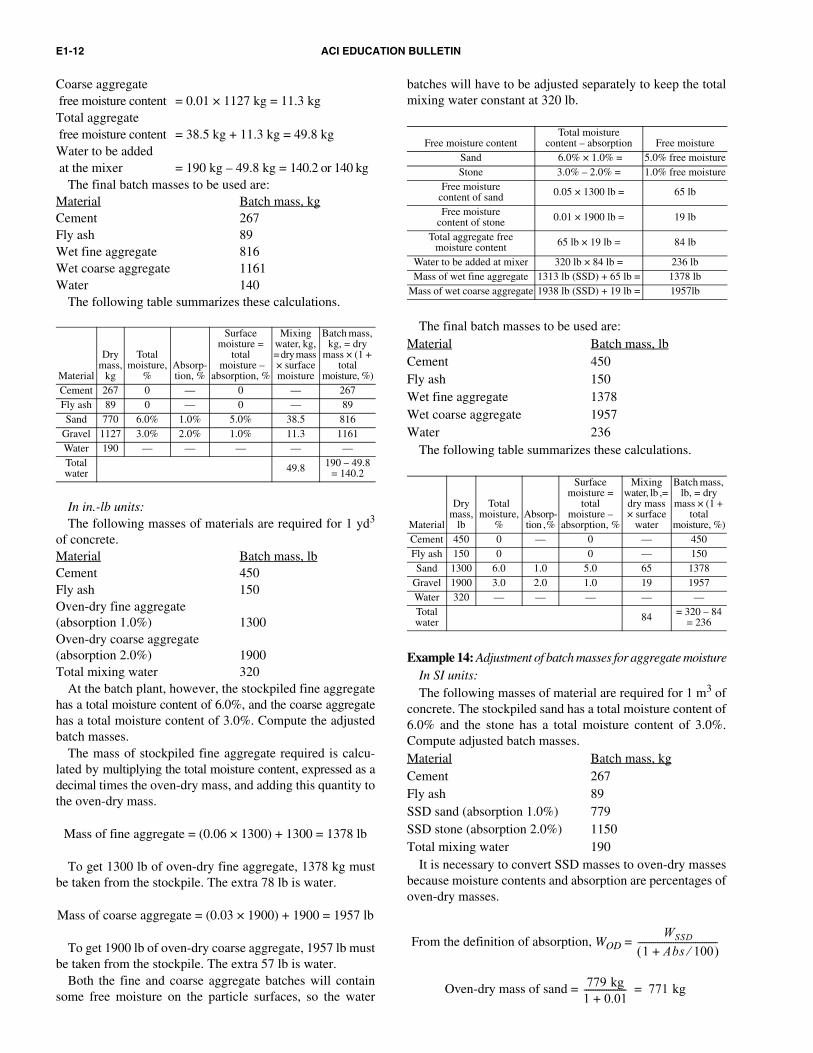
E1-12 ACI EDUCATION BULLETIN
Coarse aggregate free moisture content = 0.01 × 1127 kg = 11.3 kgTotal aggregate free moisture content = 38.5 kg + 11.3 kg = 49.8 kgWater to be added at the mixer = 190 kg – 49.8 kg = 140.2 or 140 kg
The final batch masses to be used are:Material Batch mass, kgCement 267Fly ash 89Wet fine aggregate 816Wet coarse aggregate 1161Water 140
The following table summarizes these calculations.
In in.-lb units:The following masses of materials are required for 1 yd3
of concrete.Material Batch mass, lbCement 450Fly ash 150Oven-dry fine aggregate (absorption 1.0%) 1300Oven-dry coarse aggregate(absorption 2.0%) 1900Total mixing water 320
At the batch plant, however, the stockpiled fine aggregatehas a total moisture content of 6.0%, and the coarse aggregatehas a total moisture content of 3.0%. Compute the adjustedbatch masses.
The mass of stockpiled fine aggregate required is calcu-lated by multiplying the total moisture content, expressed as adecimal times the oven-dry mass, and adding this quantity tothe oven-dry mass.
Mass of fine aggregate = (0.06 × 1300) + 1300 = 1378 lb
To get 1300 lb of oven-dry fine aggregate, 1378 kg mustbe taken from the stockpile. The extra 78 lb is water.
Mass of coarse aggregate = (0.03 × 1900) + 1900 = 1957 lb
To get 1900 lb of oven-dry coarse aggregate, 1957 lb mustbe taken from the stockpile. The extra 57 lb is water.
Both the fine and coarse aggregate batches will containsome free moisture on the particle surfaces, so the water
batches will have to be adjusted separately to keep the totalmixing water constant at 320 lb.
The final batch masses to be used are:Material Batch mass, lbCement 450Fly ash 150Wet fine aggregate 1378Wet coarse aggregate 1957Water 236
The following table summarizes these calculations.
Example 14: Adjustment of batch masses for aggregate moistureIn SI units:The following masses of material are required for 1 m3 of
concrete. The stockpiled sand has a total moisture content of6.0% and the stone has a total moisture content of 3.0%.Compute adjusted batch masses.Material Batch mass, kgCement 267Fly ash 89SSD sand (absorption 1.0%) 779SSD stone (absorption 2.0%) 1150Total mixing water 190
It is necessary to convert SSD masses to oven-dry massesbecause moisture contents and absorption are percentages ofoven-dry masses.
From the definition of absorption, WOD =
Oven-dry mass of sand =
Material
Dry mass,
kg
Total moisture,
%Absorp-tion, %
Surface moisture =
total moisture –
absorption, %
Mixing water, kg, = dry mass × surface moisture
Batch mass, kg, = dry
mass × (1 + total
moisture, %)Cement 267 0 — 0 — 267Fly ash 89 0 — 0 — 89Sand 770 6.0% 1.0% 5.0% 38.5 816
Gravel 1127 3.0% 2.0% 1.0% 11.3 1161Water 190 — — — — —Total water 49.8 190 – 49.8
= 140.2
Free moisture contentTotal moisture
content – absorption Free moistureSand 6.0% × 1.0% = 5.0% free moistureStone 3.0% – 2.0% = 1.0% free moisture
Free moisture content of sand 0.05 × 1300 lb = 65 lb
Free moisture content of stone 0.01 × 1900 lb = 19 lb
Total aggregate free moisture content 65 lb × 19 lb = 84 lb
Water to be added at mixer 320 lb × 84 lb = 236 lbMass of wet fine aggregate 1313 lb (SSD) + 65 lb = 1378 lb
Mass of wet coarse aggregate 1938 lb (SSD) + 19 lb = 1957lb
Material
Dry mass,
lb
Total moisture,
%Absorp-tion , %
Surface moisture =
total moisture –
absorption, %
Mixing water, lb , = dry mass × surface
water
Batch mass, lb, = dry
mass × (1 + total
moisture, %)Cement 450 0 — 0 — 450Fly ash 150 0 0 — 150Sand 1300 6.0 1.0 5.0 65 1378
Gravel 1900 3.0 2.0 1.0 19 1957Water 320 — — — — —Total water 84 = 320 – 84
= 236
WSSD
1 Abs 100⁄+( )------------------------------------
779 kg
1 0.01+------------------- 771 kg=

AGGREGATES FOR CONCRETE E1-13
Oven-dry mass of stone =
The final batch masses to be used are:Material Batch mass, kgCement 267Fly ash 89Wet sand 817Wet stone 1161Water 140
The following table summarizes these calculations.
In in.-lb units:The following masses of material are required for 1 yd3 of
concrete. The stockpiled sand has a total moisture content of6.0% and the stone has a total moisture content of 3.0%.Compute adjusted batch masses.Material Batch mass, lbCement 450Fly ash 150SSD sand (absorption 1.0%) 1313SSD stone (absorption 2.0%) 1938Total mixing water 320
It is necessary to convert SSD masses to oven-dry massesbecause moisture contents and absorption are percentages ofoven-dry masses.
From the definition of absorption in Section 3.3.2
WOD =
Oven-dry mass of sand =
Oven-dry mass of stone =
The final batch masses to be used are:Material Batch mass, lbCement 450Fly ash 150Wet sand 1378Wet stone 1957Water 236
The following table summarizes these calculations.
3.3.6 Alternate definition of surface moisture—Somespecifying agencies require proportions in terms of saturatedsurface-dry aggregate masses prefer to define surface moistureas a percentage of the saturated surface-dry mass. If surfacemoisture is given in terms of the saturated surface-dry mass,there is no need to convert saturated surface-dry aggregatemasses to oven-dry masses before calculating batch masses.
Surface moisture, %, =
where WS = the original mass of the sample (usually a wet ordamp mass) and WSSD = the saturated surface-dry mass ofthe sample.
A method for determining the surface moisture in fineaggregate is described in ASTM C 70. To use this method,the bulk specific gravity SSD of the aggregate must beknown. The mass of a sample to be tested for surface moistureis obtained and the amount of water displaced by the sample
Free moisture contentTotal moisture content –
absorption Free moistureSand 6.0% – 1.0% = 5.0% free moistureStone 3.0% – 2.0% = 1.0% free moisture
Free moisture content of sand 0.05 × 771 kg = 38.5 kg
Free moisture content of rock 0.01 × 1127 kg = 11.3 kg
Total aggregate free moisture content 38.5 kg × 11.3 kg = 49.8 kg
Water to be added at mixer 190 kg × 49.8 kg = 140.2 kg
Mass of wet fine aggregate 779 kg (SSD) + 38.5 kg = 817 kgMass of wet coarse
aggregate 1150 kg (SSD) + 11.3 kg = 1161 kg
Material
SSD mass,
kgAbsorp-tion, %
Totalmoisture,
%
Dry mass, kg,
= SSD mass 1 + absorp-
tion
Surface mois-
ture, %
Mixing water,
kg, = dry mass × surface moisture
Batch mass,
kg, = dry mass ×
(1 + total moisture)
Cement 267 — — 267 — — 267Fly ash 89 — — 89 — — 89Sand 779 1.0 6.0 771 5.0 38.5 817Stone 1150 2.0 3.0 1127 1.0 11.3 1161Water 190 — — — — — —
Total water 49.8
190.0 – 49.8 = 140.2
1150 kg
1 0.02+------------------- 1127 kg=
WSSD
1 Abs 100⁄+( )------------------------------------
Free moisture contentTotal moisture content –
absorption Free moistureSand 6.0% – 1.0% = 5.0% free moistureStone 3.0% – 2.0% = 1.0% free moisture
Free moisture content of sand 0.05 × 1300 lb = 65 lb
Free moisture content of stone 0.01 × 1900 lb = 19 lb
Total aggregate free moisture content 65 lb × 19 lb = 84 lb
Water to be added at mixer 320 lb × 84 lb = 236 lbMass of wet fine aggregate 1313 lb (SSD) + 65 lb = 1378 lb
Mass of wet coarse aggregate 1938 lb (SSD) + 19 lb = 1957lb
Material
SSD mass,
lbAbsorp-tion, %
Total mois-
ture, %
Dry mass, lb, = SSD
mass/1 + absorp-
tion
Surface moisture,
%
Mixing water,
lb, = dry mass × surface
moisture
Batch mass, lb,
= dry mass ×
(1 + total moisture)
Cement 450 — 450 — — 450Fly ash 150 — 150 — — 150Sand 1313 1.0 6.0 1300 5.0 65 1378Stone 1938 2.0 3.0 1900 1.0 19 1957Water 320 — — —Total water 84 320 – 84
= 236
1313 lb
1 0.01+------------------- 1300 lb=
1938 lb
1 0.02+------------------- 1900 lb=
WS
WSSD
–
WSSD
-------------------------- 100×
E1-14 ACI EDUCATION BULLETIN
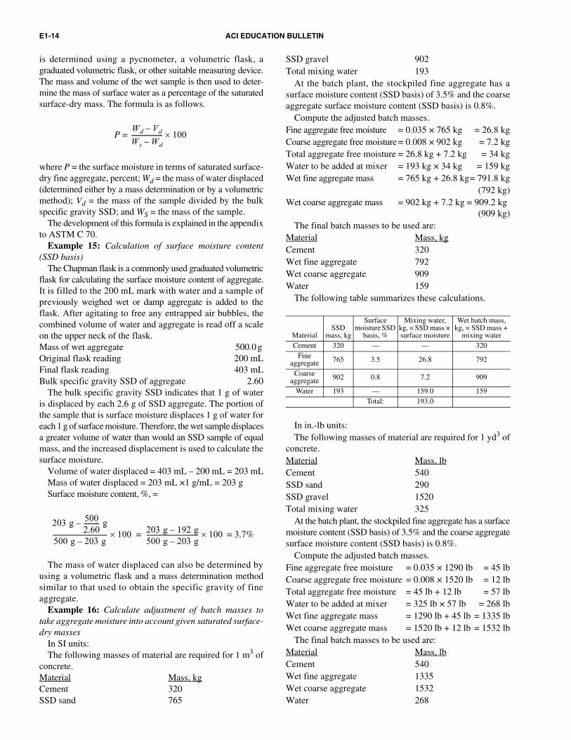
is determined using a pycnometer, a volumetric flask, agraduated volumetric flask, or other suitable measuring device.The mass and volume of the wet sample is then used to deter-mine the mass of surface water as a percentage of the saturatedsurface-dry mass. The formula is as follows.
P =
where P = the surface moisture in terms of saturated surface-dry fine aggregate, percent; Wd = the mass of water displaced(determined either by a mass determination or by a volumetricmethod); Vd = the mass of the sample divided by the bulkspecific gravity SSD; and WS = the mass of the sample.
The development of this formula is explained in the appendixto ASTM C 70.
Example 15: Calculation of surface moisture content(SSD basis)
The Chapman flask is a commonly used graduated volumetricflask for calculating the surface moisture content of aggregate.It is filled to the 200 mL mark with water and a sample ofpreviously weighed wet or damp aggregate is added to theflask. After agitating to free any entrapped air bubbles, thecombined volume of water and aggregate is read off a scaleon the upper neck of the flask.Mass of wet aggregate 500.0 g Original flask reading 200 mLFinal flask reading 403 mLBulk specific gravity SSD of aggregate 2.60
The bulk specific gravity SSD indicates that 1 g of wateris displaced by each 2.6 g of SSD aggregate. The portion ofthe sample that is surface moisture displaces 1 g of water foreach 1 g of surface moisture. Therefore, the wet sample displacesa greater volume of water than would an SSD sample of equalmass, and the increased displacement is used to calculate thesurface moisture.
Volume of water displaced = 403 mL – 200 mL = 203 mLMass of water displaced = 203 mL ×1 g/mL = 203 gSurface moisture content, %, =
= 3.7%
The mass of water displaced can also be determined byusing a volumetric flask and a mass determination methodsimilar to that used to obtain the specific gravity of fineaggregate.
Example 16: Calculate adjustment of batch masses totake aggregate moisture into account given saturated surface-dry masses
In SI units:The following masses of material are required for 1 m3 of
concrete.Material Mass, kgCement 320SSD sand 765
SSD gravel 902Total mixing water 193
At the batch plant, the stockpiled fine aggregate has asurface moisture content (SSD basis) of 3.5% and the coarseaggregate surface moisture content (SSD basis) is 0.8%.
Compute the adjusted batch masses.Fine aggregate free moisture = 0.035 × 765 kg = 26.8 kgCoarse aggregate free moisture = 0.008 × 902 kg = 7.2 kgTotal aggregate free moisture = 26.8 kg + 7.2 kg = 34 kgWater to be added at mixer = 193 kg × 34 kg = 159 kgWet fine aggregate mass = 765 kg + 26.8 kg= 791.8 kg
(792 kg)Wet coarse aggregate mass = 902 kg + 7.2 kg = 909.2 kg
(909 kg)The final batch masses to be used are:
Material Mass, kgCement 320Wet fine aggregate 792Wet coarse aggregate 909Water 159
The following table summarizes these calculations.
In in.-lb units:The following masses of material are required for 1 yd3 of
concrete.Material Mass, lbCement 540SSD sand 290SSD gravel 1520Total mixing water 325
At the batch plant, the stockpiled fine aggregate has a surfacemoisture content (SSD basis) of 3.5% and the coarse aggregatesurface moisture content (SSD basis) is 0.8%.
Compute the adjusted batch masses.Fine aggregate free moisture = 0.035 × 1290 lb = 45 lbCoarse aggregate free moisture = 0.008 × 1520 lb = 12 lbTotal aggregate free moisture = 45 lb + 12 lb = 57 lbWater to be added at mixer = 325 lb × 57 lb = 268 lbWet fine aggregate mass = 1290 lb + 45 lb = 1335 lbWet coarse aggregate mass = 1520 lb + 12 lb = 1532 lb
The final batch masses to be used are:Material Mass, lbCement 540Wet fine aggregate 1335Wet coarse aggregate 1532Water 268
Wd
Vd
–
Ws
Wd
–-------------------- 100×
203 g500
2.60---------- g–
500 g 203 g–----------------------------------- 100×
203 g 192 g–500 g 203 g–--------------------------------- 100×=
MaterialSSD
mass, kg
Surface moisture SSD
basis, %
Mixing water, kg, = SSD mass × surface moisture
Wet batch mass, kg, = SSD mass +
mixing water Cement 320 — — 320
Fine aggregate 765 3.5 26.8 792
Coarse aggregate 902 0.8 7.2 909
Water 193 — 159.0 159Total: 193.0

AGGREGATES FOR CONCRETE E1-15
The following table summarizes these calculations.
3.4—Bulk density (replaces de-emphasized term “unit weight”)
3.4.1 Definition and test method—The bulk density(previously “unit weight” or sometimes “dry-rodded unitweight”) of an aggregate is the mass of the aggregate dividedby the volume of particles and the voids between particles.Methods for determining bulk density are given in ASTM C29/C 29M. The method most commonly used requires placingthree layers of oven-dry aggregate in a container of knownvolume, rodding each layer 25 times with a tamping rod,leveling off the surface, and determining the mass of thecontainer and its contents. The mass of the container issubtracted to give the mass of the aggregate, and the bulkdensity is the aggregate mass divided by the volume of thecontainer. For aggregates having a maximum size greaterthan 37.5 mm (1-1/2 in.), jigging is used for compactinginstead of rodding and, if a loose bulk density is desired, thecontainer is simply filled to overflowing with a shovel beforeleveling it and determining its mass.
Example 17: Calculation of the bulk density of an aggregate.In SI units:
Mass of aggregate and container = 36.8 kgMass of container = 13.1 kgVolume of container = 0.0141 m3
Bulk density = (36.8 – 31.1)/0.0141 = 23.7/0.0141 = 1681 kg/m3
In in.-lb units:Mass of aggregate and container = 81.1 lbMass of container = 28.8 lbVolume of container = 0.498 ft3
Bulk density = (81.1 – 28.8)/0.498 = 52.3/0.498 = 105 lb/ft3
3.4.2 Factors affecting bulk density—Bulk density dependson the moisture content of the aggregate. For coarse aggregate,increasing moisture content increases the bulk density; forfine aggregate, however, increasing moisture content beyondthe saturated surface-dry condition can decrease the bulkdensity. This is because thin films of water on the sandparticles cause them to stick together so that they are not aseasily compacted. The resulting increase in volume decreasesthe bulk density. This phenomenon, called “bulking,” is oflittle importance if the aggregates for a concrete mixture arebatched by mass, but must be taken into account if volumetricbatching is used and moisture content varies.
Other properties that affect the bulk density of an aggregateinclude grading, specific gravity, surface texture, shape, andangularity of particles. Aggregates having neither a deficiency
nor an excess of any one size usually have a higher bulk densitythan those with a preponderance of one particle size. Higherspecific gravity of the particles results in higher bulk densityfor a particular grading, and smooth rounded aggregatesgenerally have a higher bulk density than rough angular particlesof the same mineralogical composition and grading. Therodded bulk density of aggregates used for normalweightconcrete generally ranges from 1200 to 1760 kg/m3 (75 to110 lb/ft3).
3.5—Particle shape, angularity, and surface texture3.5.1 Definition—Particle shape is defined in terms of
“compactness,” which is a measure of whether the particle iscompact in shape, that is, if it is close to being spherical orcubical as opposed to being flat (disk-like) or elongated(needle-like). Angularity refers to the relative sharpness orangularity of the particle edges and corners. The higher aparticle’s compactness (the closer it is to a sphere or cube),the lower its surface area per unit weight and therefore thelower its demand for mixing water in concrete and the lowerthe amount of sand needed in the mixture to provide work-ability. More angular and less spherical coarse aggregatesrequire higher mixing water and fine aggregate content toprovide a given workability.
Surface texture refers to the degree of roughness or irreg-ularity of the aggregate particle surface. Surface texture isusually described qualitatively using terms such as rough,granular, crystalline, smooth, or glassy rather than beingdescribed quantitatively. Smooth particles require less mixingwater and therefore less cementitious material at a fixed w/cmto produce concrete with a given workability, but also haveless surface area than rougher particles to bond with thecement paste.
3.5.2 Test methods—A number of test methods to determinecompactness or surface texture have been evaluated separatelyand in combination. While no one method has gained universalacceptance, the procedures summarized in the following (orvariations thereof) have been used reasonably widely. Threemethods have been adopted as ASTM standard procedures:ASTM C 1252, ASTM D 3398, and ASTM D 4791. InASTM D 4791, the percentage of flat or elongated particlesin an aggregate is determined by measuring the length,width, and thickness of each particle in a sample using aspecial caliper and determining whether the width-to-thickness ratio exceeds 3 (flat particles), or the length-to-width ratio exceeds 3 (elongated particles). Other specifyingagencies have also used this procedure, sometimes alsodetermining if the ratio of length to thickness exceeds 5 (flatand elongated particles). This method is feasible only forcoarse aggregate sizes. It is tedious, involving the handling ofeach individual particle in the sample. Also, it provides nomeasure of the angularity or roundness of the corners andedges, nor of surface texture.
Another test, the flakiness index, was developed in Britainand involves determining what percentage of a closely sizedsieve fraction, such as 19 to 12.5 mm (3/4 to 1/2 in.) particles,will pass through a slotted opening that is only 60% of theaverage size of the size fraction. For example, suppose that
MaterialSSD
mass, lb
Surface moisture
SSD basis, %
Mixing water, lb = SSD mass ×
surface moisture
Wet batch mass, lb = SSD mass +
mixing waterCement 540 — — 540
Fine aggregate 1290 3.5 45 1335
Coarse aggregate 1520 0.8 12 1532
Water 325 — 268 268Total: 325

E1-16 ACI EDUCATION BULLETIN
the average size of the 19 to 12.5 mm (3/4 to 1/2 in.) fractionis 16 mm (5/8 in.), and 60% of that is 9.5 mm (3/8 in.). Aparticle in this size fraction is thus considered to be flaky ifits least dimension is less than 9.5 mm (3/8 in.). The percentageof flaky particles in each of several size fractions is determined,and low percentages indicate aggregates with a high degreeof compactness. This procedure as well is time consuming,because each particle is handled to see if it can be fitted throughthe appropriate slot; again, only coarse aggregate is considered.
Fine and coarse aggregate characteristics relating to shape,angularity, and surface texture can also be measured in anintegrated fashion by measuring the percentage of voids inan aggregate compacted in a standard manner in a containerof known volume. ASTM C 1252 provides a method for thedetermination of percent voids in fine aggregate. The absolutevolume of the solid mass of a sample in a container is deter-mined by dividing the mass of the aggregate by the productof its bulk specific gravity and the density of water. The voidpercentage (percent voids) is the volume of the container minusthe volume of the solid mass of the sample, expressed as apercentage of the container volume. The more angular andrough an aggregate, the greater the percentage of voids. Inaddition, because the grading of the sample affects thepercentage of voids, the test must be run either using astandardized grading or measuring the percentage of voidsin each size fraction.
ASTM C 1252 includes a procedure for fine aggregateinvolving the measurement of voids in three separate sizefractions, and also a procedure using a fixed grading for bothfine and coarse aggregates to obtain companion voidpercentages related to shape and texture. The mixing waterrequired to produce concrete with a given level of workabilitycan be related to shape and texture, as indirectly measured byvoids in the fine aggregate. The flow rate of aggregatethrough a funnel-like orifice has also been used as a measureof shape and texture, and has been found to be closely relatedto percent voids.
The particle index (ASTM D 3398) is determined bymeasuring the percentage of voids of each aggregate sizefraction at two levels of compaction, and then extrapolatingthe straight line through the two data points back to theloose-voids condition with no compactive effort. In essence,this gives a property related to voids at loose compactionwithout the problems of trying to reproduce a loose-voidscondition that is more difficult to standardize. The particle indexis determined by the following formula for each size, and aweighted index is then calculated for the overall grading.
I = 1.25V10 – 0.25V50 – 32.0
where I = the particle index, V10 = the percent voids at 10 dropscompaction, and V50 = the percent voids at 50 drops compaction.
Another somewhat tedious procedure involving thehandling of each particle is to count the particles with morethan one (or sometimes more than two) crushed faces. Thismethod is usually applicable only to coarse aggregate, and issubject to a wide variation in results, sometimes due to the
opinion of the operator as to what constitutes a face producedby crushing. It has been standardized as ASTM D 5821.
3.5.3 Significance of particle shape, angularity, and surfacetexture—The shape, angularity, and surface texture of theindividual particles of sand, crushed stone, gravel, blastfurnace slag, or lightweight aggregate making up an aggregatehave an important influence on the workability of freshlymixed concrete and the strength of hardened concrete. Fine-aggregate particle shape and texture affect concrete mainlythrough their influence on the workability of fresh concrete.Other factors being equal, more mixing water is required toobtain a particular level of slump or workability in freshconcrete using fine aggregates that are angular and rough,rather than using fine aggregates that are rounded andsmooth. This in turn affects the required w/cm for a particularcementitious content, or the required cementitious contentfor a particular w/cm.
The influence of fine aggregate shape and texture on thestrength of hardened concrete is almost entirely related to theresulting w/cm of the concrete, provided that the fine aggregatehas a grading within normally accepted limits and that gradingis taken into account in selecting concrete proportions.
Coarse aggregate shape and texture also affect requirementsfor mixing water and for the w/cm in a manner similar to that offine aggregate. Coarse aggregate particles, however, due to theirmuch smaller ratio of surface area to volume, affect strengththrough a more complex relationship between the bond betweenaggregate and cement paste and the concrete w/cm. Therefore,the effects of aggregate shape and texture on the strength ofhardened concrete should not be over-generalized.
Failure of a concrete strength specimen most often startsas microcracks between the paste or mortar and the surfacesof the largest coarse aggregate particles. This is a bond failuremode. Angular, rough-textured aggregates, for example, havean increased surface area for bond to the cement paste whencompared with rounded, smooth particles of similar size.
Considering all of the factors that have an effect on concretestrength, the following appear to be most important:
1. The surface area available for bond to the cement paste.Here, the shape and texture of the largest particles is mostimportant.
2. The surface texture of the largest pieces, which affectsthe bond strength per unit of surface area. The mineralogyand crystal structure of these largest pieces affects bondstrength per unit area as well.
3. The relative rigidity of the aggregate particles comparedwith the surrounding paste or mortar. The closer the deformationcharacteristics of the aggregate are to that of the surroundingmedia, the lower are the stresses developed at particle surfaces.
4. Maximum size of the aggregate. For a given w/cm, as thesize of the larger particles is increased, the likelihood of bondfailure between paste and aggregate increases because stressesat the interface are higher than those for smaller particles.
Factors that give higher intrinsic bond strength are relativelyunimportant in fine aggregates because of the large total surfacearea available for bond and the lower stresses around smallparticles. Likewise, the larger surfaces of angular sandscompared with rounded sands are of no particular benefit to

AGGREGATES FOR CONCRETE E1-17
bond strength. This leads to the conclusion that the shape andsurface texture of fine aggregate affect the amount of mixingwater required for a given workability and that the effects ofdifferent fine aggregates on concrete strength can be predictedfrom a knowledge of their effects on mixing water and w/cm.
For coarse aggregate, however, the situation is quite differentand the final effects on strength are more difficult to predictdue to the importance of bond-strength characteristics in thelarger particles. This is the fundamental reason why differentmaximum sizes of coarse aggregates, different grading, anddifferent sources of coarse aggregate produce differentcurves of compressive strength versus w/cm. For example, invery high-strength concrete mixtures where coarse aggregatebond is critical, angular cubical-shaped coarse aggregatesgenerally give higher strengths than either rounded smoothaggregates or those with a large proportion of flat or elongatedpieces; also, smaller maximum size aggregates, such as the12.5 or 19 mm (1/2 or 3/4 in.) fractions, give higher compressivestrengths than do larger sizes, such as the 37.5 and 50 mm(1-1/2 and 2 in.) maximum sizes. Where extremely highstrengths are not required, acceptable concrete can be madewith many different types of aggregates, with some variation inthe w/cm required to provide the needed strength.
3.6—Abrasion and impact resistance3.6.1 Definition and significance—The abrasion and impact
resistance of an aggregate is its ability to resist being worn awayby rubbing and friction or shattering upon impact. It is a generalmeasure of aggregate quality and resistance to degradationdue to handling, stockpiling, or mixing.
3.6.2 Test method—The most common test method forabrasion and impact resistance of coarse aggregate is theLos Angeles machine method (ASTM C 131 for aggregatebetween 2.36 and 37.5 mm [No. 8 sieve opening and 1-1/2 in.],and ASTM C 535 for aggregate between 19 and 75 mm [3/4and 3 in.]). This test method combines the effects of impact andabrasion by tumbling aggregate particles together with steelballs in a slowly revolving steel drum. A specified quantity ofaggregate is placed in the steel drum with an abrasive chargeof steel balls of a specified diameter. The drum is rotated for500 or 1000 revolutions, during which a shelf inside the drumtumbles and drops the aggregate and balls. The percentage ofthe aggregate worn away is determined by sieving the aggregateusing the 1.70 mm (No. 12) sieve and mass measurement.Specifications often set an allowable upper limit on thepercentage loss of mass. ASTM C 33, “Concrete Aggregates,”specifies a maximum mass loss of 50% for gravel, crushedgravel, or crushed stone. Comparisons of results of aggregateabrasion tests with those of abrasion resistance of concretedo not generally show a direct correlation, however. Theabrasion resistance of concrete is generally related to itscompressive strength.
3.7—Soundness3.7.1 Definition and mechanism of deterioration—
Soundness of an aggregate refers to its ability in concrete towithstand aggressive exposure, particularly due to weather.In areas with severe or moderate winters, a major cause of
aggregate deterioration in exposed concrete is freezing andthawing. If an aggregate particle absorbs so much water thatits pores are nearly completely filled, it may not accommo-date the expansion that occurs when water turns to ice. As iceforms, the resulting expansion pushes unfrozen waterthrough the aggregate pores and the resistance to this flowresults in pressures that may be high enough to crack theparticle. These pressures may crack the aggregate particle,and, in concrete, the surrounding concrete as well. This isknown as “D-cracking.” The developed pressure depends onthe rate of freezing and the particle size above which the particlewill fail if completely saturated. This critical size depends onthe porosity, pore size, and total pore volume of the aggregate;the permeability or rate of discharge of water flowingthrough the aggregate; and the tensile strength of the particle.
For fine-grained aggregates with low permeability (suchas some cherts), the critical particle size may be in the rangeof normal aggregate sizes. It is higher for coarse-grainedmaterials or those with pore systems interrupted by numerouspores too large to hold water by capillary action. For thesematerials, the critical size may be too large to be of consequence,even though absorption may be high. Also, if potentiallyvulnerable aggregates are dry when used or are used in concretesubjected to periodic drying while in service, they may neverbecome sufficiently saturated to cause failure under freezing-and-thawing cycling.
3.7.2 Test methods—Several methods have been used topredict the performance of aggregates under exposure tofreezing and thawing. One of these is evaluation of pastperformance. If aggregates from the same source havepreviously given satisfactory service when used in concrete,the aggregate may be considered acceptable. Aggregatesnot having a service record may be considered acceptable ifthey perform satisfactorily in concrete specimens subjected tofreezing-and-thawing tests. In these tests (ASTM C 666),concrete specimens are subjected to alternate cycles of freezing,either in air or water, and thawing in water. Deteriorationis measured by the reduction in the frequency of an energywave passed through the specimens, which is related to thedynamic modulus of elasticity of the specimens.
Some specifications may require that resistance toweathering be demonstrated by the sodium sulfate ormagnesium sulfate soundness test (ASTM C 88). This testconsists of immersing a sample of the aggregate specimen ina sulfate solution for a prescribed number of cycles, oven-drying the sample, and determining the percentage loss ofmass. This test sometimes produces inconsistent results, inthat aggregates behaving satisfactorily in the test may produceconcrete having low freezing-and-thawing resistance;conversely, aggregates performing poorly may produceconcrete with adequate resistance. This may be attributed inpart to the fact that the aggregates in the test are not surroundedby cement paste as they would be when used in concrete.
3.7.3 Pop-outs—A pop-out is the breaking away of a smallportion of a concrete surface due to internal pressure thatleaves a shallow, usually conical, depression, as shown inFig. 6.

E1-18 ACI EDUCATION BULLETIN
Pop-outs result from freezing and thawing of porous aggre-gate that is critically saturated or from alkali-silica reaction(refer to the following). Due to the critical size effect mentionedpreviously, pop-outs caused by freezing can sometimes beminimized by reducing the maximum aggregate size. In otherinstances, however, it is necessary to remove harmfulsubstances such as chert, opaline shale, coal, or lignite that alsocause pop-outs.
3.8—Chemical stability3.8.1 Definition and reaction mechanisms—Aggregates
that are chemically stable will neither react chemically withcement in a harmful manner nor be affected chemically bynormal external influences. In some areas, reactions can occurbetween aggregates made up of certain minerals and alkalispresent in concrete, from internal or external sources. Onesuch reaction, alkali-silica reaction (ASR), involves certainsilica minerals found in some aggregates. The process startswhen alkalis (sodium and potassium oxide) from concreteingredients enter into solution and combine with reactivesiliceous minerals to form an alkali-silica gel that has atendency to absorb water and swell. This swelling may causeabnormal expansion and cracking of concrete in a characteristicrandom or map pattern (Fig. 7). The most common constituentscausing ASR are siliceous minerals such as tripolitic chert,
strained quartz, microcrystalline quartz, chalcedony and opal,natural volcanic glass, and andesite or tridymite. Thesereactive materials can occur in quartzose, chalcedonic oropaline cherts, opaline or siliceous limestone, opalineshale, and acid to intermediate glassy volcanic rocks.Some phyllites, argillites, quartzites, granite gneisses, andquartz gravels are also reactive because of the reactivity ofstrained or microcrystalline quartz. Refer to ASTM C 294for a description of aggregate mineralogy. Another kind ofharmful reaction is alkali-carbonate reaction (ACR), whichnormally results from dedolomitization (the conversion ofmagnesium-rich limestone to calcium-rich limestone) andoccurs between alkalis and argillaceous dolomitic lime-stone with appreciable amounts of clay. These rocks have acharacteristic microstructure that can be recognized by anexperienced petrographer. ACR is less common than ASR.
3.8.2 Test methods—Field service records, when available,generally provide the best information for selection of aggre-gates based on chemical stability. The service record shouldconsider the severity of the exposure and the characteristicsof the cementitious materials used with the aggregate. If anaggregate has no field service record, a petrographic exami-nation (ASTM C 295) is useful. A petrographic examinationinvolves looking at the aggregate particles under a microscope,and includes additional procedures for determining themineral constituents present. Such an examination by aqualified petrographer is often helpful in identifying poten-tially reactive aggregates. In addition, several ASTM tests areavailable for identifying reactive aggregates, as described inthe following.
Tests for ASR potential:ASTM C 227, the mortar bar test, is used to determine the
potentially expansive alkali-silica reactivity of cement-aggregate combinations. In this test, the expansion developedin mortar bars during storage under prescribed temperatureand moisture conditions is measured. While the mortar bartest can be used for either fine or coarse aggregates, it takesat least 3 to 6 months.
ASTM C 289, known as the quick chemical test, is usedfor identifying potentially reactive siliceous aggregates. Itcan be completed in 24 hours. Results are based on the degreeof reaction (change in alkalinity and amount of dissolved silica)when a crushed specimen of the aggregate in question isplaced in a concentrated alkaline solution of sodium hydroxideat a high temperature.
ASTM C 1260 is a rapid mortar bar test developed tosupplement slower test methods. In this test, mortar bars areimmersed in a strong alkaline solution (sodium hydroxide) atan elevated temperature. The potential for reactivity is assessedbased on the length change of the mortar bars after twoweeks of this immersion.
ASTM C 1567 is similar to ASTM C 1260 but test combi-nations of cementitious materials such as cement, fly ash,and ground granulated blast furnace slag with the aggregatesthat are being evaluated. The sample preparation and storageconditions are similar to those of ASTM C 1260.
ASTM C 1293, a 1-year concrete prism test, involvesmaking concrete with the test aggregate. The alkali content
Fig. 6—Pop-out due to unsound aggregate particle.
Fig. 7—Cracking caused by abnormal expansion due toalkali-aggregate reaction.

AGGREGATES FOR CONCRETE E1-19
of the concrete is increased by adding sodium hydroxide tothe mixture ingredients. The concrete prisms, typicallymeasuring 75 x 75 x 250 mm (3 x 3 x 10 in.), are placed incontainers at a prescribed temperature and humidity, similarto those used in ASTM C 227. Expansion is measured over1 year, although longer test periods have sometimes been used.
Considerable controversy exists regarding how to assessthe potential reactivity of an aggregate based on these testmethods. While ASTM C 227 seems to correlate well withfield performances for rapidly reacting siliceous aggregates,it can fail to identify slowly reactive aggregates that showdistress in the field. ASTM C 289 does not work well withcarbonate and siliceous aggregates, and is recommended foruse only as a screening test. ASTM C 1260 is a severe testand is also recommended as a screening test. Although it hasbeen shown to identify slowly reacting aggregates that arenot identified by ASTM C 227, it also incorrectly identifiesaggregates with a good service record. In Canada, ASTM C1293 is considered to provide the best correlation with fieldperformance. For the best indication of potential for aggregatereactivity, ASR tests should be performed in conjunctionwith a petrographic examination of the aggregate.
Tests for ACR potential:ASTM C 586, known as the rock-cylinder test, is used to
determine potentially expansive dolomitic aggregates. Lengthchanges are determined for a cylindrical sample of the rockimmersed in a sodium hydroxide solution. Expansive tendenciesare usually observable after 28 days of immersion. Differentexpansion criteria at different ages are used by variousorganizations.
ASTM C 1105 is a concrete prism test for ACR similar toASTM C 1293 for ASR. The test is typically run for approx-imately 6 months, but a 1-year exposure is preferred.
Dolomitic aggregates with the potential for causing concreteexpansions due to ACR can be identified with relative assuranceby an experienced petrographer.
3.8.3 Corrective measures—Several options are availablefor dealing with aggregates found to be potentially reactivewith alkalis. Laboratory tests and field performance showthat expansion due to ASR can be reduced or eliminated byadding a pozzolan or ground slag as cementitious materialsto the concrete mixture in sufficient quantities, using ablended cement, or by using a lithium-based admixture. Somepozzolans, however, are less effective in reducing expansion.It is necessary to test the ability of a given pozzolanic materialor ground granulated blast-furnace slag to control ASR, andan accelerated mortar test (ASTM C 441 or ASTM C 1567)is usually used for this purpose. Long-term tests on concrete(such as ASTM C 1293) can also be used. Another way ofcontrolling expansion due to ASR is to use a low-alkali cement.A potentially reactive aggregate should be rejected only after allother available options are exhausted. In very rare instances,the best course of action may be to choose a different aggregate.
Expansions due to ACR, in contrast, cannot be easilycontrolled by modifying the concrete mixture. Pozzolans andslag are not effective in reducing expansions. Cement with analkali content less than 0.4% (sodium oxide equivalent) hasbeen recommended in some cases. Potential expansion due
to ACR is best controlled by the choice of aggregate. Recom-mended methods are selective quarrying to eliminate potentiallyreactive layers in a quarry, blending the aggregate, or reducingthe maximum size of the aggregate.
3.9—Harmful substances in aggregates3.9.1 Types of harmful substances—Harmful substances
that may be present in aggregates include organic impurities,silt, clay, lignite, and certain lightweight and soft particles.These may occur naturally in the aggregate, or may beintroduced when the aggregates are transported in gondolacars, barges, or trucks previously used to haul thosecontaminating substances. Aggregate can be contaminatedby oil during handling.
3.9.2 Effects of harmful substances—Organic impuritiessuch as peat, humus, organic loam, and sugar delay settingand hardening of concrete, and sometimes lead to deterioration.
Silt, clay, or other materials passing the 75 µm (No. 200)sieve may be present as dust or may form a coating on aggre-gate particles. Excessive amounts of this material may undulyincrease the water required to produce a given slump for theconcrete, or, if the amount of fine material varies from batchto batch, may cause undesirable fluctuations in the slump, aircontent, and strength. Thin coatings of dust on the coarseparticles may weaken the bond between cement paste andcoarse aggregate.
Coal, lignite, lightweight cherts, and other lightweight orsoft materials such as wood, may affect the durability ofconcrete if present in excessive amounts. If these impuritiesoccur at or near the concrete surface, they may result in pop-outs or staining.
3.9.3 Test methods—The test for organic impurities insands for concrete (ASTM C 40) detects the presence of someinjurious organic impurities. In this test, sodium hydroxidesolution is poured over a sample of the sand in a bottle that isthen sealed with a stopper, shaken vigorously, and allowed tostand for 24 hours. The color of the liquid above the sample isthen compared with a color standard. If the liquid’s color isdarker than the standard, the sand is considered to containinjurious organic compounds and it should be tested furtherbefore being approved for use in concrete. Because all organicmaterials resulting in a positive reaction (dark color) are notnecessarily harmful, another test (ASTM C 87) is usuallyconducted to determine the effect of the impurities onstrength. Mortar cubes are made using the sand in questionand a sample of the same sand, previously washed in sodiumhydroxide to remove the organic materials. After 7 days ofcuring, the cubes are tested in compression. The strength ofcubes containing the sand in question is then divided bythe strength of cubes containing washed sand, and if thisstrength ratio is at least 0.95, the sand in question is consideredto be acceptable.
The amount of material passing the 75 µm (No. 200) sieveis determined by washing a sample of the aggregate over a75 µm (No. 200) sieve (ASTM C 117) and determining theresulting loss in mass as a percentage of the original sampleweight. ASTM C 33, “Concrete Aggregates,” limits thepercentage of material finer than a 75 µm (No. 200) sieve to

E1-20 ACI EDUCATION BULLETIN
3% for fine aggregates used in concrete subject to abrasion,and to 5% for fine aggregate used in all other concrete. Formanufactured fine aggregates where the minus No. 200 finescan be shown to be free of clay or shale, the limits are increasedto 5 and 7%, respectively. Similarly, for coarse aggregate,material passing the 75 µm (No. 200) sieve is limited to 1%,or to 1.5% for crushed aggregates if the dust is essentiallyfree of clay and shale.
The percentage of lightweight particles can be determinedby the test for lightweight pieces in aggregate (ASTM C123). A sample of the aggregate to be tested is placed in aheavy liquid and floating pieces are skimmed off and weighed.The percentage of lightweight pieces is then calculated.Where surface appearance of the concrete is important, theamount of coal or lignite is limited to 0.5% for both fine andcoarse aggregates by ASTM C 33, while for all other concretes,the maximum is 1%. Requirements for soft particles are givenin Table 3 of the most recent ASTM specifications for concreteaggregates, ASTM C 33.
CHAPTER 4—SAMPLING AGGREGATES4.1—Variability in aggregates
In the previous section, methods for measuring aggregateproperties are discussed. Aggregates vary from unit to unitand within each unit, however, and it is not economicallyfeasible to test all of a unit, whether that unit is an entirestockpile or a smaller batch. Thus, a sampling proceduremust be used. That is the subject of this section.
4.2—Sampling4.2.1 Definition—A sample is a small portion of a larger
volume or group of materials such as a stockpile, batch,carload, or truckload about which information is wanted.Sampling is the process of obtaining samples. The propertiesof the sample are considered to represent the properties of thelarger unit from which it is taken.
4.2.2 Significance of variability—A series of samples canbe used to provide information about average properties andthe variability of those properties. This is important for manyreasons. For example, given two lots of sand, suppose that theFM of each needs to be known. A single sample could be takenfrom each lot, a sieve analysis conducted, and the FM calculated.Further, suppose that in both cases, the FM is 2.70. Bothsamples can be said to have the same FM, but what about thelots? Is it reasonable to say that the sand in each lot has a FMof 2.70? Perhaps not. There would be more confidence in aconclusion if the results of sieve analysis from several samples,all from the same lot, were available. The following resultsmight be obtained if five samples were taken from each lot.
Fineness modules of five samples:Lot A Lot B2.70 2.702.75 2.952.63 2.472.68 2.882.74 2.50Average = 2.70 Average = 2.70
The average of each five-sample set is still 2.70, so therewould be more confidence in concluding that the sand ineach lot has an FM of 2.70. Something else about the lotsmust be determined, however. Assuming that the correctsampling and testing procedures were used, it is obvious thatLot B is more variable than Lot A. For Lot B, the FM rangesfrom 2.47 to 2.95, while for Lot A, it ranges only from 2.63to 2.75. Concrete made with sand from Lot B is likely to bemore variable in quality than concrete made with sand fromLot A, because aggregate fineness affects slump if watercontent is held constant. Thus, the sand from Lot A would bepreferable.
Therefore, test results on samples reveal the averageproperties of an aggregate and may also indicate the variabilityin these properties. Acceptance or rejection of an aggregatemust be made based on results of tests on samples, andreasonable decisions can be made only if samples are takencorrectly and in accordance with a sampling plan.
4.2.3 Sampling plans—Detailed discussion of how toformulate a sampling plan for aggregates is beyond the scopeof this Bulletin. Each plan depends on the sampling situationand on the information to be extracted from the measurementson the sample. For instance, one might be interested infinding only the average gradation, or one might want theaverage gradation and the variation in gradation within a lot ofaggregate. Formulation of an appropriate plan requires under-standing of the fundamentals of probability sampling and aknowledge of the product being sampled. Models for proba-bility sampling, significance, and interpretation are given inASTM E 141, “Recommended Practice for Acceptance ofEvidence on the Results of Probability Sampling.” Otherpertinent references are listed in the Reference section of thisBulletin.
4.2.4 Sampling methods—Methods of sampling aggre-gates are described in ASTM D 75, “Standard Methods ofSampling Aggregates.” Samples should preferably be takenfrom conveyor belts or flowing aggregate streams, but mayalso be taken from stockpiles. In sampling from a conveyorbelt, three approximately equal increments (explained inthe following) are selected at random from the unit beingsampled and are combined to form a field sample of a sizeequal to or exceeding the minimum recommended in thefollowing section dealing with sample size. The conveyor beltis stopped while the sample increments are obtained. Toobtain the increment, two templates are spaced and inserted sothat the material contained between them provides anincrement of the required weight. All material between thetemplates is carefully scooped into a suitable container,including the fines on the belt, which are collected with abrush and dust pan and added to the container.
Three approximately equal increments are also selected atrandom when sampling from a flowing aggregate stream (binor belt discharge). Each increment is taken from the entire crosssection of the material as it is being discharged. This usuallyrequires the construction of a specially built pan large enough tointercept the entire cross section and hold the requiredamount of material without overflowing.

AGGREGATES FOR CONCRETE E1-21
Sampling from stockpiles should be used only as a last resort,particularly when the sampling is done for the purpose ofdetermining aggregate properties that may depend on thegrading of the sample. When samples must be obtained froma stockpile, it is necessary to design a sampling plan for thespecific case under consideration.
4.2.5 Number and size of field samples—The requirednumber of field samples depends on the importance andvariability of the properties to be measured. Guidance fordetermining the number of samples required to obtain thedesired level of confidence in test results is given in thepreviously mentioned ASTM E 105, E 122, and E 141. Theunit of material represented by a single sample may varywidely, but is usually approximately 45 to 50 tons.
The required size of field samples must be based on the typeand number of tests to which the material is to be subjected.Minimum sample size varies with nominal maximum size ofthe aggregate, and recommendations are as follows.
Test portions are extracted from the field sample using asample splitter or other appropriate methods as described inASTM C 702, “Reducing Field Samples of Aggregate toTesting Size.”
4.2.6 Sample containers—If samples are to be shipped toa laboratory for testing, the container should be clean, aseven small amounts of some materials (such as those thatadhere to sugar or fertilizer sacks) may represent seriouscontamination. Also, the container should be tightly sealedto prevent loss of fines and external contamination. The sampleshould be identified clearly, inside and outside the container,along with information giving the date of sampling, the kindof aggregate sampled, the quantity represented by the sample,the location and other conditions of sampling, the specifyingauthority or reason for test, and the kind of test desired.
CHAPTER 5—BLAST-FURNACESLAG AGGREGATES
5.1—Blast-furnace slag5.1.1 Definition—Blast-furnace slag is a nonmetallic
combination of crystalline silica and other materials thatform in a molten condition on the surface of molten iron beingproduced in a blast furnace. When the molten slag is pouredinto pits or banks and permitted to cool and solidify slowly
under atmospheric conditions, the result is air-cooled slag.When molten blast-furnace slag is rapidly agited with acontrolled amount of water, or when it is injected with acontrolled amount of water, steam, or water-bearing compressedair, the result is expanded blast-furnace slag. When the moltenslag is suddenly quenched in water, the result is granulated slag.However it is cooled, slag can be crushed and screened into avariety of sizes. Only air-cooled and expanded blast furnaceslags are used as concrete aggregates. Ground granulatedslag is ground to a fine powder and used as a cementitiousmaterial. Air-cooled slag is discussed in the rest of thissection. Expanded slag is discussed in the section on light-weight aggregates.
5.1.2 Properties—Slag has many noninterconnected internalvoids, resulting in a structurally strong aggregate with relativelylow bulk specific gravity and bulk density. Because the poresare coarse and not interconnected, slag aggregate has goodfreezing-and-thawing durability. Slag aggregate is not harmedby alkalis, and it contains no clay, shale, chert, organiccompounds, or other harmful substances usually restrictedin specifications for natural aggregates.
Crushed blast furnace slag is roughly cubical in shape andhas a rough surface texture. ASTM C 33, “Standard Specifi-cations for Concrete Aggregates,” does not specify a LosAngeles abrasion loss requirement for air-cooled blast-furnace slag because it has been determined that the test isnot meaningful with respect to slag. It does, however, specify aminimum compacted bulk density of 1120 kg/m3 (70 lb/ft3).
Air-entraining agents are recommended to entrain air inconcrete with slag aggregates to aid workability even innonfreezing and thawing applications. Entrained air shouldof course be used in all concrete exposed to freezing andthawing. Entrained air is especially desirable when slag-aggregate concrete is to be pumped. It is also desirable tohave the slag in a saturated condition before batching andmixing to ensure that mixing water is not absorbed by thecoarse aggregate.
5.1.3 Availability—Air-cooled blast-furnace slag is availableprimarily in regional areas around steel-producing centerswhere blast furnaces are used to extract iron from iron ore
CHAPTER 6—LIGHTWEIGHT AGGREGATES6.1—Introduction to lightweight aggregates
Lightweight aggregates are defined as aggregates of lowdensity, such as: (a) expanded or sintered clay, shale slate,diatomaceous shale, perlite, vermiculite or slag; (b) naturalpumice, scoria, volcanic cinders, tuff, and diatomite; or (c)sintered fly ash or industrial cinders used in lightweightconcrete.
6.2—Definition of lightweight-aggregate concreteLightweight-aggregate concrete has a substantially lower
bulk density than that of concrete made with gravel orcrushed stone. This lower bulk density results from usinglightweight aggregates, either natural or manufactured. Manytypes of aggregates are classified as lightweight, and are used toproduce concretes with a wide range of densities and strengths.These include low-density concretes, structural lightweight
Size of samplesNominal maximum size of aggregates
Approximate minimum mass of field samples, kg (lb)
Fine aggregate2.36 mm (No. 8) 10 (25)4.75 mm (No. 4) 10 (25)
Coarse aggregate9.5 mm (3/8 in.) 10 (25)
12.5 mm (1/2 in.) 15 (35)19.0 mm (3/4 in.) 25 (55)25.0 mm (1 in.) 50 (110)
37.5 mm (1-1/2 in.) 75 (165)50 mm (2 in.) 100 (220)
63 mm (2-1/2 in.) 125 (275)75 mm (3 in.) 150 (330)
90 mm (3-1/2 in.) 175 (385)

E1-22 ACI EDUCATION BULLETIN
concretes, and moderate-strength lightweight concretes, each ofwhich is discussed in more detail in the following, along withthe types of aggregates normally used in its production.
6.3—Low-density concretes and associated aggregates
Low-density concretes, whose density seldom exceeds800 kg/m3 (50 lb/ft3), are used chiefly as insulation. Whiletheir thermal insulation values are high, their compressivestrengths are low, ranging from approximately 0.7 to 7.0 MPa(100 to 1000 psi). Vermiculite and perlite are the most commonaggregates used in this type of concrete. Vermiculite is amicaeous mineral. When heated, layers of combined waterin the mica’s laminar structure are converted to steam, andthe material disintegrates by peeling off in successive layers,each of which swells and opens up. Perlite is a volcanic glasscontaining enough combined water so that when it is heatedquickly, the internally generated steam expands violentlyand breaks the material into small expanded particles. Thebulk density of vermiculite and perlite ranges from 96 to192 kg/m3 (6 to 12 lb/ft3).
6.3.1 Structural lightweight concrete and associatedaggregates—Structural lightweight concretes have densitiesranging from 1360 to 1920 kg/m3 (85 to 120 lb/ft3) andminimum compressive strengths of 17.0 MPa (2500 psi).Their insulating efficiency is lower than that of low-densityconcretes, but substantially higher than that of normalweightconcretes. The most common aggregates used in this type ofconcrete are expanded slags; sintering-grate expanded shale,clay, or fly ash; and rotary-kiln expanded shale, clay, or slate.
Sintering can produce either crushed or pelletized aggregates.Crushed aggregates are produced using raw materials that eithercontain organic matter that can serve as fuel, or have beenmixed with fuel such as finely ground coal or coke. The rawmaterials are premoistened and burned so that gases areformed causing expansion. The resulting clinker is thencooled, crushed, and screened to the required gradation. Thefinished product tends to be generally sharp and angular witha porous surface texture. Pelletized aggregates are producedby mixing clay, pulverized shale, or fly ash with water and fuel;pelletizing or extruding that mixture; and then burning it.The resultant aggregate particles are generally spherical orcylindrical.
In the rotary kiln process, raw material such as shale, clay,or slate is introduced in a continuous stream at the upper endof a rotary kiln. As the material slowly moves toward theburner at the lower end, the heat, slope, and slow rotation ofthe kiln cause the material to soften and to trap internallyforming gases into an internal cellular structure. In onevariation of this process, the expanded (bloated) material isdischarged, cooled, and then crushed and screened to therequired aggregate gradations. The resultant particles tend tobe cubical or angular in shape and have a porous surfacetexture. Alternatively, before being introduced into the kiln,the raw material is presized by crushing and screening, or bypelletizing. The individual particles then bloat without stickingtogether. They tend to have a smooth shell over a cellularinterior. These two variants can be combined to produce
coarse aggregate consisting mostly of uncrushed particles,obtained by screening, and fine particles obtained by crushingthe fired product.
6.3.2 Moderate-strength lightweight concrete and associatedaggregates—Moderate-strength lightweight concretes havea density and strength approximately midway between thoseof low-density and structural concretes, and are sometimesdesignated as fill concrete. They are usually made with pumiceor scoria aggregate. Pumice is a spongy lava from whichsteam or gas escaped while it was still hot, and has tube-like,interconnected void pores. Scoria is a volcanic cinder whosepore structure consists mostly of isolated voids.
6.3.3 Properties—Due to their cellular structure, the bulkspecific gravity of lightweight aggregates is lower than thatof normalweight aggregates. The bulk specific gravity oflightweight aggregates also varies with particle size, beinghighest for fine particles and lowest for coarse particles. Thisis because crushing destroys larger voids, producing fineraggregates with lower porosity. With present ASTMmethods, it is difficult to accurately determine bulk specificgravity and absorption for lightweight aggregates, due toproblems in consistently achieving a saturated surface-dry state.Thus, in designing concretes using lightweight aggregates, aspecific gravity factor is used instead of the bulk specificgravity. This factor is found in the same way as the bulk specificgravity SSD previously described except that Mass S is themass of the aggregate at the stockpile moisture, and the massof the sample in water is measured at a specified number ofminutes after immersion. Additional information of specificgravity factors for lightweight aggregates is given in theAppendix of ACI 211.2.
The bulk density of structural lightweight coarse aggregateis normally from 480 to 1040 kg/m3 (30 to 65 lb/ft3), signif-icantly lower than that of normalweight aggregates. The bulkdensity of structural lightweight fine aggregate is normallyfrom 720 to 1120 kg/m3 (45 to 70 lb/ft3). For aggregates withthe same gradation and particle shape, bulk density is essentiallyproportional to specific gravity. Although aggregates are usuallybatched by mass, the volume proportion of the aggregatedetermines the final yield (volume of the resulting concrete).For this reason, the bulk density of lightweight aggregateis generally checked daily. Variations in bulk density are usuallydue to changes in grading or particle shape, and can causevariations in concrete yield.
Particle shape and surface texture can vary considerablyfor lightweight aggregates produced by different methods.Particles are usually roughly spherical, but can be quiteangular. Surface texture may range from relatively smoothwith small exposed pores, to irregular with small to largeexposed pores. These characteristics in both fine and coarseaggregates affect the workability, water requirement, andcement content of lightweight-aggregate concrete, just asthey affect concrete made with normalweight aggregates.
In general, grading requirements for lightweight aggregatesare similar to those for normalweight aggregates. Light-weight aggregates, however, require a larger percentage bymass of material retained on finer sieve sizes because thespecific gravity increases with the decreasing particle size.

AGGREGATES FOR CONCRETE E1-23
Thus, to get an adequate volume of smaller particles, thepercent by mass of these particles must be increased. Gradingrequirements for lightweight aggregates are given in ASTMC 330. Maximum size grading designations generally availableare 19, 12.5, and 9.5 mm (3/4, 1/2, and 3/8 in.). Sieve analysisis conducted as for normal aggregates, except that the test sampleof fine aggregate has a smaller mass, and the mechanicalsieving time is only 5 minutes. These modifications areintended to prevent clogging of smaller sieves and to preventbreakage of the more friable particles during sieving. For coarseaggregate, the test sample must be at least 3 L (0.10 ft3)in volume.
Lightweight aggregates, due to their cellular structure, canabsorb more water than normalweight aggregates. In a 24-hourabsorption test, they generally absorb from 5 to 20% by massof dry aggregate, depending on the pore structure of theaggregate. Normally, under conditions of outdoor storage instockpiles, total moisture content does not exceed two-thirdsof that value. This means that lightweight aggregates usuallyabsorb water when placed in a concrete mixture, and theresulting rate of absorption is important in proportioninglightweight concrete. For further information on proportioninglightweight concrete, the reader is referred to ACI 211.2,“Recommended Practice for Selecting Proportions forStructural Lightweight Concrete.”
The maximum compressive strength attainable in concretemade with a given lightweight aggregate may depend on theaggregate itself. The concept of “strength ceiling” may beuseful in this regard. A mixture is near its strength ceilingwhen similar mixtures containing the same aggregates and withhigher cement contents have only slightly higher strengths.The strength ceiling represents a point of diminishing returns,beyond which an increase in cement content does not produce acommensurate increase in strength. This ceiling is influencedpredominantly by the coarse aggregate. The strength ceilingcan be increased appreciably by reducing the maximum size ofthe coarse aggregate for most lightweight aggregates, especiallyweaker and more friable ones. As the maximum size of theaggregate is decreased, however, the density of the resultingconcrete increases.
CHAPTER 7—RECYCLED AGGREGATES7.1—Introduction to recycled aggregates
When concrete pavements, structures, sidewalks, curbs,and gutters are removed, they become waste or can beprocessed for reuse. The resulting concrete must either bedisposed of in landfills, or crushed for subsequent use asaggregate base material or as aggregate in new concrete.Crushing the material and using it as coarse aggregate in newconcrete makes sense because it reduces waste and reduces theneed for virgin aggregate. Recycled aggregate may be of betterquality than some virgin aggregate. While recycled aggregate ishandled similarly to new aggregate, some differences betweennew and recycled aggregate must be addressed.
7.1.1 Definition—Recycling aggregate involves breaking oldconcrete (typically pavement), removing the reinforcement,and crushing the resulting material to a specified size andgradation. While any type of pavement or other concrete may
be recycled, certain aggregates or certain types of mixturesmay require testing of the material to be recycled. Examplesinclude aggregates prone to D-cracking or concretes withASR potential.
It is desirable to maximize the amount of coarse aggregateproduced when concrete is recycled. Recycled fine aggregatenormally accounts for approximately 25% of the finishedrecycled material. New concrete mixtures can contain bothfine and coarse recycled aggregate. While up to 100% of thecoarse aggregate can be recycled material, the percentage of fineaggregate is usually limited to 10 to 20%, with the remainderbeing virgin material. This is because of the high absorptionof recycled fine aggregates, explained further in the following.
7.1.2 Properties—Gradation and surface condition of recycled aggregate—
Almost any gradation can be achieved with recycled aggregate.Crushing may leave some residual dust on the aggregatesurfaces. While this does not normally pose a problem, theaggregate must sometimes be washed before use.
Specific gravity of recycled aggregate—The specificgravity of crushed recycled aggregate is lower than that ofotherwise identical virgin aggregate, usually approximately2.2 to 2.5 in the saturated surface-dry (SSD) condition. Asparticle size decreases, so does specific gravity. Recycled sandhas a specific gravity of approximately 2.0 to 2.3 (SSD).
Absorption of recycled aggregates—Due to the cementmortar attached to the particles, the absorption of recycledaggregates is much higher than that of otherwise identicalvirgin aggregates, typically 2 to 6% for coarse aggregate andhigher for fine aggregate. This high absorption can make theresulting fresh concrete less workable. To offset this, recycledaggregate should be sprinkled with water before the concreteis mixed, or extra water should be added to the mixture.Because fine aggregate made by crushing concrete is veryangular and has a high absorption, it is generally necessaryto limit it to approximately 10 to 20% of the total amount offine aggregate in the mixture.
Durability of recycled aggregates—Abrasion loss andsulfate soundness are usually not of concern for recycledaggregate. Residual chlorides in a mixture, as from applicationof deicing salts to a pavement, are usually below thresholdvalues for both fine and coarse aggregates and are not a concerneither. Recycled aggregates made from concrete exposed tosalt water, however, should receive further chemical andphysical testing for their suitability for use in concrete.
Concretes with D-cracking aggregates should be testedbefore being used as recycled aggregates in concrete thatwill be subjected to freezing and thawing exposures.
While recycled concrete can be used as coarse aggregatein new concrete pavements, its ASR potential should bedetermined before such use. Several characteristics are helpfulin determining the ability of this aggregate to perform withoutdeleterious ASR during the pavement life. The alkali levelsof both the recycled concrete and the new concrete can affectthe expansion of the final concrete. To assess ASR potential, thefollowing characteristics of the recycled aggregate should beinvestigated: the original alkali level of the old concrete, the

E1-24 ACI EDUCATION BULLETIN
expansion of the old concrete, the remaining potential forexpansion, and the alkali content of the new concrete.
Alkali-silica reactivity in concrete containing recycledaggregates that have shown to be ASR reactive can bemitigated in many of the same ways as concrete made withvirgin aggregates. Refer to Section 3.8.3.
CHAPTER 8—SELECTED REFERENCESON AGGREGATES
American Association of State Highway and Transporta-tion Officials, “Standard Specifications for TransportationMaterials and Methods of Sampling and Testing,” AASHTO,Washington, D.C.
AASHTO T 210, “Aggregate Durability Index for Fineand Coarse Aggregate.”
AASHTO T 210, “Aggregate Durability Index for Fineand Coarse Aggregate.”
AASHTO TP 58, “Resistance of Coarse Aggregate toDegradation by Abrasion in the Micro Deval Apparatus.”
ACI 213R-03, “Guide for Structural Lightweight AggregateConcrete,” American Concrete Institute, Farmington Hills,Mich., 2003.
ACI 221R-96, “Guide for Use of Normalweight andHeavyweight Aggregates in Concrete,” American ConcreteInstitute, Farmington Hills, Mich., 1996.
ACI 221.1R-98, “Report on Alkali-Aggregate Reactivity,”American Concrete Institute, Farmington Hills, Mich., 1998.
ACI Manual of Concrete Inspection, SP-2, 9th Edition,American Concrete Institute, Farmington Hills, Mich., 1999.
For referenced ASTM standards, visit the ASTM website,www.astm.org, or contact ASTM Customer Service [email protected]. For Annual Book of ASTM Standardsvolume information, refer to the standard’s Document Summarypage on the ASTM website. The following ASTM standardsare published by ASTM International, West Conshohoken, Pa.
ASTM C 29/C 29M, “Standard Test Method for BulkDensity (”Unit Weight”) and Voids in Aggregate.”
ASTM C 33-03, “Standard Specifications for ConcreteAggregates.”
ASTM C 40-04, “Standard Test Method for OrganicImpurities in Fine Aggregates for Concrete.”
ASTM C 70-94(2001), “Standard Test Method for SurfaceMoisture in Fine Aggregate.”
ASTM C 87-03, “Standard Test Method for Effect ofOrganic Impurities in Fine Aggregate on Strength of Mortar.”
ASTM C 88-99a, “Standard Test Method for Soundness ofAggregates by Use of Sodium Sulfate or Magnesium Sulfate.”
ASTM C 117-04, “Standard Test Method for MaterialsFiner than 75-µm (No. 200) Sieve in Mineral Aggregates byWashing.”
ASTM C 123-04, “Standard Test Method for LightweightParticles in Aggregate.”
ASTM C 127-04, “Standard Test Method for Density,Relative Density (Specific Gravity), and Absorption of CoarseAggregate.”
ASTM C 128-04, “Standard Test Method for Density,Relative Density (Specific Gravity), and Absorption of FineAggregate.”
ASTM C 131-03, “Standard Test Method for Resistance toDegradation of Small-Size Coarse Aggregate by Abrasion andImpact in the Los Angeles Machine.”
ASTM C 136-04, “Standard Test Method for Sieve Anal-ysis of Fine and Coarse Aggregates.”
ASTM C 142-97(2004), “Standard Test Method for ClayLumps and Friable Particles in Aggregates.”
ASTM C 227-03, “Standard Test Method for PotentialAlkali Reactivity of Cement-Aggregate Combinations(Mortar-Bar Method).”
ASTM C 289-03, “Standard Test Method for PotentialAlkali-Silica Reactivity of Aggregates (Chemical Method).”
ASTM C 294-04, “Standard Descriptive Nomenclature forConstituents of Concrete Aggregates.”
ASTM C 295-03, “Standard Guide for Petrographic Exam-ination of Aggregates for Concrete.”
ASTM C 330-04, “Standard Specification for LightweightAggregates for Structural Concrete.”
ASTM C 331-04, “Standard Specification for LightweightAggregates for Concrete Masonry Units.”
ASTM C 332-99, “Standard Specification for LightweightAggregates for Insulating Concrete.”
ASTM C 535-03ε1, “Standard Test Method for Resistance toDegradation of Large-Size Coarse Aggregate by Abrasionand Impact in the Los Angeles Machine.”
ASTM C 566-97(2004), “Standard Test Method for TotalEvaporable Moisture Content of Aggregate by Drying.”
ASTM C 637-98a(2003), “Standard Specification forAggregates for Radiation-Shielding Concrete.”
ASTM C 638-92(2002), “Standard Descriptive Nomen-clature of Constituents of Aggregates for Radiation-ShieldingConcrete.”
ASTM C 641-98ε1, “Standard Test Method for StainingMaterials in Lightweight Concrete Aggregates.”
ASTM C 586-99, “Standard Test Method for PotentialAlkali Reactivity of Carbonate Rocks for Concrete Aggregates(Rock Cylinder Method).”
ASTM C 702-98(2003), “Standard Practice for ReducingSamples of Aggregate to Testing Size.”
ASTM C 1137-97, “Standard Test Method for Degradationof Fine Aggregate Due to Attrition.”
ASTM C 1252-03, “Standard Test Methods for Uncom-pacted Void Content of Fine Aggregate (as Influenced byParticle Shape, Surface Texture, and Grading).”
ASTM C 1260-01, “Standard Test Method for PotentialAlkali Reactivity of Aggregates (Mortar-Bar Method).”
ASTM C 1293-01, “Standard Test Method for Determinationof Length Change of Concrete Due to Alkali-Silica Reaction.”
ASTM C 1524/C 1524M-02a, “Standard Test Method forWater-Extractable Chloride in Aggregate (Soxhlet Method).”
ASTM C 1567-04, “Standard Test Method for Determiningthe Potential Alkali-Silica Reactivity of Combinations ofCementitious Materials and Aggregate.”
ASTM D 75-03, “Standard Practice for Sampling Aggre-gates.”
ASTM D 448-03a, “Standard Classification for Sizes ofAggregate for Road and Bridge Construction.”

AGGREGATES FOR CONCRETE E1-25
ASTM STP 169 C, “Significance of Tests and Propertiesof Concrete and Concrete-Making Materials,” ASTM Inter-national, West Conshohocken, Pa., 1994.
IS 413, “Diagnosis and Control of Alkali-AggregateReactions in Concrete,” Portland Cement Association,Skokie, Ill., 1997.
TB014, “Recycling Concrete Pavement,” American ConcretePavement Association,” Skokie, Ill., 1993.
CHAPTER 9—GLOSSARYAbrasion resistance—Ability of a surface to resist being
worn away by rubbing and friction.Absorption—The mass of water contained in the pores of
a saturated surface-dry aggregate expressed as a percentageof the oven-dry mass of the aggregate; also the process bywhich a liquid is drawn into a porous solid body.
Admixture—A material other than water, aggregates, andhydraulic cement that is used as an ingredient in concrete ormortar and is added to the batch immediately before orduring mixing.
Aggregate—Granular material such as natural sand,manufactured sand, gravel, crushed stone, and blast furnaceslag that, when bound together by cement paste, forms concrete.
Air entrainment—The inclusion of air in the form of verysmall bubbles during the mixing of concrete.
Alkali-aggregate reaction—Chemical reaction in mortaror concrete between alkalis from portland cement or othersources and certain constituents of some aggregates; undercertain conditions, harmful expansion of the concrete ormortar may result.
Batch—Quantity of concrete or mortar mixed at one time.Blast-furnace slag—The nonmetallic product, consisting
essentially of silicates and aluminosilicates of calcium andof other bases, which is developed in a molten conditionsimultaneously with iron in a blast furnace.
Bleeding—The flow of mixing water toward the surface ofnewly placed concrete caused by the settlement of solidmaterials.
Bulk density (replaces deprecated term “unit weight”)—For aggregate, the mass of a unit volume of aggregate material(the unit volume includes the volume of individual particlesand the volume of the voids between the particles).
Cement, portland—The product obtained by pulverizingclinker consisting essentially of hydraulic calcium silicateswith calcium sulfates as an interground addition; whenmixed with water it forms the binder in portland cementconcrete or other hydraulic cement concretes.
Coarse aggregate—Aggregate predominantly retained onthe 4.75 mm (No. 4) sieve.
Colorimetric test—A procedure used to indicate theamount of organic impurities present in fine aggregate.
Concrete—A material consisting of a binder within whichaggregate particles are imbedded; in hydraulic cement concrete,the binder is a mixture of hydraulic cement and water.
Crushed gravel—The product resulting from the artificialcrushing of gravel with nearly all fragments having at leastone face resulting from fracture.
Crushed stone—The product resulting from the mechanicalcrushing of rocks, boulders, etc., with substantially all facesof the particle having resulted from the crushing operation.
Elongated particle—A piece of aggregate having the ratioof length to width of its circumscribing prism greater than aspecified value.
Fine aggregate—Aggregate passing the 9.5 mm (3/8 in.)sieve and almost entirely passing the 4.75 mm (No. 4) sieveand predominantly retained on the 75 µm (No. 200) sieve.
Fineness modulus—A factor obtained by adding the totalpercentages of an aggregate sample coarser than each of aspecified series of sieves, and dividing the sum by 100; in theU.S., the sieves are 150 µm, 300 µm, 600 µm, 1.18 mm,2.36 mm, 4.75 mm, 9.5 mm, 19.0 mm, 37.5 mm, 75 mm, and150 mm (No. 100, No. 50, No. 30, No. 16, No. 8, No. 4,3/8 in., 3/4 in., 1-1/2 in., 3 in., and 6 in.).
Flat particle—A piece of aggregate having the ratio ofwidth to thickness of its circumscribing prism greater than aspecified value.
Free moisture—Moisture not retained or absorbed byaggregate. Also called surface moisture.
Grading, Gradation—The distribution of particles ofaggregate among various sizes; usually expressed in terms oftotal percentages larger or smaller than each of a series ofsieve openings or the percentages between certain ranges ofsieve openings.
Gravel—Granular material predominantly retained on the4.75 mm (No. 4) sieve and resulting from natural disinte-gration and abrasion of rock or processing of weakly-boundconglomerate.
Harsh mixture—A concrete mixture that lacks desiredworkability and consistency due to a deficiency of mortar oraggregate fines.
Igneous rocks—Rocks that have solidified from a moltensolution.
Lightweight aggregates—Aggregates that may range indry loose mass (weight) from 96 to 1120 kg/m3 (6 to 70 lb/ft3)and are used in making lightweight concrete.
Los Angeles abrasion test—A procedure used to measurethe abrasion resistance of aggregates.
Manufactured sand—See stone sand.Maximum size of aggregate—In specifications for, or
descriptions of, aggregate, the smallest sieve through whichthe entire amount of aggregate is required to pass.
Metamorphic rocks—Rocks altered and changed fromtheir original igneous or sedimentary form by heat, pressure,or a combination of both.
Mineral admixture—Finely-divided mineral powder suchas hydrated lime, fly ash, bentonite, and pulverized talc orstone used as an admixture for concrete.
Mortar bar test—A procedure used to determine whetheran aggregate will expand excessively, due to the alkali-aggregate reaction, when used in concrete.
Nominal maximum size of aggregate—In specificationfor, or descriptions of, aggregate, the smallest sieve throughwhich the entire amount of aggregate is permitted to pass.

E1-26 ACI EDUCATION BULLETIN
Pop-out—The breaking away of small portions of a concretesurface due to internal pressure that leaves a shallow, typicallyconical, depression.
Pozzolan—A siliceous or siliceous and aluminous materialthat will, in finely divided form and in the presence of moisture,chemically react with calcium hydroxide at ordinary temper-atures to form cementing compounds.
Pycnometer—a vessel for determination of specific gravityof liquids or solids
Reactive aggregate—Aggregate containing substancescapable of reacting chemically with the products of solutionor hydration of the portland cement in concrete or mortar underordinary conditions of exposure, sometimes resulting inharmful expansion, cracking, or staining.
Roundness—A term referring to the relative sharpness orangularity of aggregate particle edges or corners.
Sand—Granular material passing the 9.5 mm (3/8 in.)sieve and almost entirely passing the 4.75 mm (No. 4) sieveand predominantly retained on the 75 µm (No. 200) sieve,and resulting from natural disintegration and abrasion ofrock or processing of completely friable sandstone.
Saturated surface-dry—Condition of an aggregate particlewhen the permeable voids are filled with water and no wateris on the exposed surfaces.
Sedimentary rock—Rocks formed by the deposition ofplant and animal remains, and of materials formed by thechemical decomposition and physical disintegration of igneous,sedimentary, or metamorphic rocks.
Sieve analysis—Determination of the proportions of particleslying within selected size ranges in a granular material byseparation on sieves of different size openings.
Slag—See blast-furnace slag.Slump—A measure of consistency of freshly-mixed concrete
obtained by placing the concrete in a truncated cone ofstandard dimensions, removing the cone, and measuring thesubsidence of the concrete to the nearest 6 mm (1/4 in.).
Soundness—For aggregate, the ability to withstand theaggressive action to which concrete containing it might beexposed, particularly that due to weather.
Specific gravity—For aggregate, the mass of the aggregatedivided by the mass of an equal volume of water. Nowidentified as relative density
Sphericity—A property of aggregate relating to the ratio ofsurface area to volume; spherical or cubical particles have ahigher degree of sphericity than flat or elongated particles.
Stone sand—Fine aggregate produced by crushing rock,gravel, or slag. Also called manufactured sand.
Surface moisture—See free moisture.Surface texture—Degree of roughness or irregularity of
the exterior surfaces of aggregate particles or hardened concrete.Water-cementitious material ratio (w/cm)—The ratio of
the amount of water, exclusive only of that absorbed by theaggregates, to the amount of cementitious material in a concrete,preferably stated as a decimal by mass.
Workability—That property of freshly mixed concrete ormortar that determines the ease and homogeneity with whichit can be mixed, placed, compacted, and finished.
Yield—The volume of freshly mixed concrete producedfrom a known quantity of ingredients, usually calculated bydividing the total mass of ingredients by the density of thefreshly mixed concrete.

As ACI begins its second century of advancing concrete knowledge, its original chartered purposeremains “to provide a comradeship in finding the best ways to do concrete work of all kinds and inspreading knowledge.” In keeping with this purpose, ACI supports the following activities:
· Technical committees that produce consensus reports, guides, specifications, and codes.
· Spring and fall conventions to facilitate the work of its committees.
· Educational seminars that disseminate reliable information on concrete.
· Certification programs for personnel employed within the concrete industry.
· Student programs such as scholarships, internships, and competitions.
· Sponsoring and co-sponsoring international conferences and symposia.
· Formal coordination with several international concrete related societies.
· Periodicals: the ACI Structural Journal and the ACI Materials Journal, and Concrete International.
Benefits of membership include a subscription to Concrete International and to an ACI Journal. ACImembers receive discounts of up to 40% on all ACI products and services, including documents, seminarsand convention registration fees.
As a member of ACI, you join thousands of practitioners and professionals worldwide who share acommitment to maintain the highest industry standards for concrete technology, construction, andpractices. In addition, ACI chapters provide opportunities for interaction of professionals and practitionersat a local level.
American Concrete Institute38800 Country Club DriveFarmington Hills, MI 48331U.S.A.Phone: 248-848-3700Fax: 248-848-3701
www.concrete.org
American Concrete Institute®
Advancing concrete knowledge