Embed Size (px)
Citation preview

Proceedings of the 2011 Winter Simulation Conference S. Jain, R.R. Creasey, J. Himmelspach, K.P. White, and M. Fu, eds.
AGENT-BASED CONCEPTUAL MODEL REPRESENTATION USING BPMN
Bhakti S. S. Onggo Onder Karpat
Lancaster University The University of Liverpool Management Science Information Technology
Lancaster University Management School Online Higher Education Lancaster, LA1 4YX, UK Liverpool, L69 3BX, UK
ABSTRACT
In a simulation project, a good conceptual model representation is critical for communicating conceptual models between stakeholders. A conceptual model describes the problem domain and model specifica-tions. The description of the problem domain includes the objectives, inputs, outputs, content, assump-tions and simplifications made in the model. The model specifications are used to specify the model’s be-havior. This article focuses on the representation of the model content (structure, boundary and level of detail) component of an agent-based simulation (ABS) model. For this, we propose the use of Business Process Model and Notation (BPMN) from the Object Management Group. A Web-based visual model-ing tool has been developed using JavaScript to demonstrate how BPMN can be used to represent an ABS conceptual model and how the tool translates the conceptual model into code ready for execution using Repast HPC.
1 INTRODUCTION
Conceptual modeling is the process of abstracting a model from a real or proposed system into a concep-tual model (Robinson 2010). There is a point in a simulation project where the conceptual modeling pro-cess occurs inside an individual modeler’s mind. This ‘thinking’ process includes reflection on how to structure the problem and how the simulation model should be designed to help decision-makers solve the problem to hand, subject to certain constraints. At some point in the simulation project, the conceptual model needs to be communicated to other stakeholders (such as clients, simulation modelers and domain experts). Nance (1994) refers to explicit representation of the conceptual model as the communicative model. The importance of the quality of communication between stakeholders to make a simulation pro-ject (Robinson and Pidd 1998) successful makes the role of (explicit) conceptual model representation important. Onggo (2010) classifies methods for conceptual model representation into three categories: textual, pictorial and multi-faceted. It is clear that the definition of a conceptual model must affect its representation. Unfortunately, there is no single accepted definition of what a conceptual model is. Robinson (2010) discusses various concep-tual model definitions and concludes that complete consensus is difficult to achieve. This is due partly to the wide range of applications of computer simulation; each application domain may have different char-acteristics (such as project scale and team size) and requirements (such as the criticality of model reusa-bility). This article uses the conceptual model definition proposed in Robinson (2010), i.e., a “conceptual model is a non-software specific description of the computer simulation model (that will be, is or has been developed), describing the objectives, inputs, outputs, content, assumptions and simplifications of the model.” Based on the separation between domain-oriented components and design-oriented components in a conceptual model, as proposed in Lacy et al. (2001), we extend Robinson’s definition to include de-sign-oriented components. These provide a representation of the problem domain which is consistent with
671978-1-4577-2109-0/11/$26.00 ©2011 IEEE

Onggo and Karpat
Robinson’s conceptual model definition. Design-oriented components add detailed specifications to the conceptual model. The proliferation of visual interactive modeling software (VIMS) has made the distinc-tion between domain-oriented and design-oriented components less clear. For example, most VIMS al-lows simulation model developers to define the structure of a model (domain-oriented) and give a detailed specification of how a component in the model will behave over time (design-oriented). The Winter Simulation Conference (WSC) participants may have noticed that simulation modeling paradigms, such as discrete-event simulation (DES), agent-based simulation (ABS) and system dynamics (SD), have been frequently used in WSC articles. Two of the key differences among the three paradigms are the way simulation modelers view the world and how the view is represented in a model. Readers in-terested in the differences between the three paradigms should refer to Morecroft and Robinson (2006), Brailsford, Desai, and Viana (2010), Siebers et al. (2010) and Macal (2010). In the context of conceptual model representation, most commercial VIMS dedicated to DES use a variant of the process flow diagram to represent the structure of a DES model and provide functionalities (which may include a specialized programming language) to specify the behavior of each element in the model. Similarly, VIMS dedicated to SD mostly uses a variant of the stock-and-flow diagram to represent the structure of a model and functionalities to specify the dynamic behavior of the model. This may sug-gest that conceptual model representation in DES and SD has been dominated by the process flow and stock-and-flow diagrams, respectively. On the other hand, ABS is younger than either DES or SD. Its popularity has increased partly due to the availability of high quality micro-data, increases in computing power, and the advancement of analytical behavior modeling. Hence, research into conceptual model rep-resentation in ABS is rather new. As with DES and SD, a conceptual model in ABS describes the domain-oriented components (such as the objectives, inputs, outputs, content, assumptions and simplifications made in the model) and design-oriented components (such as detailed specifications of model behavior). In this article, we focus mainly on the model content that describes the boundary, level of detail and structure of ABS conceptual models. Many existing methods for ABS conceptual model representation (such as pseudo-code, DEVS, and Petri Net) are less friendly to business users who may not be familiar with software engineering concepts or formal methods. For this reason, we propose the use of Business Process Model and Notation (BPMN) which is a standard designed for business users. We will also demonstrate that by using a simple specifi-cation language and adding a few BPMN extensions we can translate a conceptual model represented in BPMN into an executable form for a target simulation engine. For this purpose, we have developed a Web-based visual modeling tool where users can draw an ABS model (suitable for business users) and add detailed specifications to it (more suitable for simulation modelers) to make it executable for a target platform. In this article, we have chosen Repast HPC (Collier 2010) as the target platform. The remainder of this chapter is organized as follows. In Section 2, we briefly explain BPMN and its core elements, an overview of ABS and the methods commonly used for conceptual model representation in ABS. This is followed by a discussion of why BPMN is suitable for ABS conceptual model representation. Section 3 explains the design and implementation of the Web-based visual modeling tool that supports the use of BPMN for ABS conceptual model representation.
2 BUSINESS PROCESS MODEL AND NOTATION (BPMN)
BPMN is a business process modeling language and standard controlled by the Object Management Group (OMG). The current specification document (BPMN 2.0) states that the objective of the standard is “to provide a notation that is readily understandable by all business users, from the business analysts that create the initial drafts of the processes, to the technical developers responsible for implementing the technology that will perform those processes, and finally, to the business people who will manage and monitor those processes” (OMG 2010). The objective clearly indicates that BPMN comprises two parts: a business view and a technical view. The business view targets the business analysts who will use BPMN to create descriptive business processes models which can be communicated and analyzed. The technical view targets technical developers who will need to add detailed technical specifications to the models to
672
Onggo and Karpat
make them executable. The separation between the two parts in BPMN is in line with the separation be-tween the domain-oriented components and design-oriented components in a conceptual model. This has made BPMN even more appealing for use in conceptual modeling. Business users who are more interest-ed in the domain-oriented components can use the business view part of BPMN. Likewise, the design-oriented components which require detailed specifications of the model can be represented using the technical part of BPMN.
BPMN 2.0 defines four types of conformance: process modeling conformance, process execution conformance, BPEL (Business Process Execution Language) process execution conformance and chore-ography modeling conformance (OMG 2010). Conformance to process modeling conformance requires a modeling tool to support both process and collaboration diagrams. The other conformance types have not been implemented in our software tool and, hence, will not be discussed in this article. The detailed re-quirements for process modeling conformance and the explanation on other conformance types are given in the BPMN 2.0 specification document.
2.1 BPMN Diagrams (Process Diagram and Collaboration Diagram)
The process diagram is used to represent various business process models. BMPN 2.0 divides business process models into two categories: private and public. A private (or internal) process model describes ac-tivities internal to an organization. A public process model describes the interactions between activities internal to an organization and one or more external organizations. Internal activities that do not interact directly with external organizations are not shown.
The collaboration diagram is used to model the interactions between two or more organizations (or business entities within the same organization). The collaboration model appears similar to a set of inter-acting public process models except that all private activities (including those that do not interact directly with other organizations) are shown. A collaboration diagram allows a public process to be represented as a black box when we cannot see (or are not interested in) the internal activities of the process. BPMN 2.0 also supports the choreography diagram and the conversation diagram which are not part of conformance to process modeling. Hence, these diagrams will not be discussed in this article. Figure 1 shows examples of: a private process model (a), a public process model (b), and a collaboration model (c).
2.2 BPMN Core Elements
BPMN supports a number of core graphical elements that can be divided into five categories: flow ob-jects, data, connecting objects, swimlanes and artifacts. Table 1 shows the general shape of the core com-ponents. Flow objects, such as events, activities and gateways, are used to define the behavior of a pro-cess. For example, an event may trigger an activity to start and, when the activity ends, a gateway is used to decide whether to send a successful completion event or raise an error exception event. BPMN does not have elements to describe the structure of the data used in the model. Instead, it provides links to external-ly defined data structures using various elements such as data objects, data input, data output and data stores. Connecting objects are used to connect flow objects to each other or to other elements. There are four types of connection: sequence flows, message flows, association, and data association. Swimlanes, which comprise pool and lanes, are used to group a number of elements. For example, an organization can be represented as a pool and each department within the organization can be represented as a lane inside the pool. Subsequently, a process inside a specific lane represents a process internal to the department. Finally, artifacts are used to provide additional information to a model. This can be in the form of group annotation or text annotation. OMG (2010) provides a detailed specification of all BPMN core elements.
673

Onggo and Karpat a)
b)
c)
Figure 1: (a) Private process model, (b) Public process model, and (c) Collaboration model
Table 1: BPMN core components – adapted from OMG (2010)
Element Notation Element Notation Event
Pool
Activity
Lane
Gateway
Data object, Da-ta input, Data output
Sequence flow Data store
Message flow Group
Association Text annotation
Data association
Representation methods frequently used in the ABS literature include flow charts, pseudo-code, Petri Nets, DEVS and UML. Flow charts and pseudo-code are commonly used to describe algorithms. The be-havior of agents in many ABS models is often expressed as logical rules. Hence, it is very common to see flow charts and pseudo-code (or even computer code itself) used to represent agent behaviors. To take an example from the last Winter Simulation Conference, Allen and Davis (2010) use a flow chart to repre-
674
Onggo and Karpat
sent their ABS model, based on social impact theory, to predict the yield of STEM majors in the US. Petri Nets and its variants are used to represent agents and agent behaviors in multi-agent systems (MAS), for example, in Moldt and Wienberg (1997). Although there are some differences between ABS and MAS (North and Macal 2007), the representation of agents and agent behaviors is a topic common to the two fields. We have also seen ABS model representation in DEVS and its variants. For example, Saple and Yilmaz (2006) use DEVS to represent an ABS model for fault management in computer networks. In his survey, Alan (2010) finds that the majority of popular ABS frameworks and tools are based on Object Oriented principles, i.e., they use classes and methods to represent agents and agent behaviors. Hence, it is not surprising to see many articles using UML diagrams (or their variants) to represent agents and agent behaviors. Bauer, Müller, and Odell (2001) and Odell, Parunak, and Bauer (2000) propose Agent UML (AUML) which extends UML to make it more suitable for modeling agents and agent-based systems in general. The AUML website (http://www.auml.org) provides a number of articles demonstrating the use of UML diagrams and their variants to represent agents and their behaviors. If we look at the representation adopted by ABS software tools, in the early years of ABS, software tools required users to represent ABS models as computer code, using either general or specialized pro-gramming languages (e.g., early versions of Repast used Java, C# or Python). Today, visual representa-tion of agents and their behaviors has increasingly been adopted. For example, the current version of Re-past Simphony has a visual modeling tool which allows modelers to use flow charts to represent ABS models. To take another example, a recent version of AnyLogic uses diagrams, such as state charts (based on UML state transition diagrams) and action charts (based on flow charts), to represent ABS models. In this article we propose to use BPMN to represent ABS models. There are a number of reasons which are mainly based on our motivation to promote the use of ABS to the wider business community. Among the reasons are:
BPMN is a standard designed for business users. The standard is supported by big vendors such as IBM, Oracle, SAP, Unisys, etc. BPMN supports process description using diagrams, detailed specifications that can be attached
to each element in BPMN diagrams, and process execution for automated workflow or simula-tion. This matches well with the concepts explained in the introduction of this article, i.e., the conceptual model (both domain-oriented components and design-oriented components) and the implementation of a conceptual model that can be executed on a computer;
The use of BPMN does not require any license fee. There are a number of software tools that support BPMN and the number is likely to grow. Some of them are free (e.g., ARIS Express from http://www.ariscommunity.com/ and Activiti from http://www.activiti.org/).
A method for conceptual model representation in ABS needs to support the representation of agents,
agent behaviors and the environment (spatial or non-spatial, such as networks). The collaboration diagram has been designed to support process-oriented model view. However, it also recognizes the role of partic-ipants in a model (in the form of pools and lanes) which can be utilized to represent an agent-oriented model view. For example, a BPMN pool can be used to represent an agent. The behavior of agent can be represented using a set of BPMN elements contained within the BPMN pool that represent the agent. BPMN elements support events, activities, gateways (selection) and various connection types (flow). At this stage, we have yet to establish a formal proof of the equivalence between BPMN and a Turing Ma-chine, which can demonstrate the general computing power of BPMN. This is the technique used by Schruben and Yucesan (1988) to prove the generality of a Simulation Graph (or an Event Graph). How-ever, experienced programmers may appreciate that combinations of BPMN elements have the potential to represent various complex agent behaviors. There are two ways of representing the environment in BPMN. First, the environment can be represented as an agent. Like an agent, some environment factors can be active (or have behavior), i.e., they can change their states even in the absence of any actions by agents. Another approach is to extend BPMN via a new element to represent certain environmental fac-tors. The main advantage of this approach is that we can design the software tool to be extendable. We
675

Onggo and Karpat
can add or remove modules/libraries as required. This is the approach that we use in the example that will be discussed in the next section, where we will add a new BPMN artifact to allow modelers to define the network structure of agents. We should also note that although the earlier BPMN versions were designed for a process-oriented model view, BPMN 2.0 introduces choreography and conversation diagrams which are designed to describe the interactions between actors in a model which can be used to provide a more agent-oriented model view.
3 AGENT-BASED MODEL AND NOTATION DESIGNER (ABMN DESIGNER)
3.1 Software Architecture
In order to demonstrate the suitability of BPMN for ABS we have developed Web-based VIMS (Visual Interactive Modeling Software) called Agent-based Model and Notation Designer (ABMN Designer). ABMN Designer can be accessed from http://www.lancs.ac.uk/staff/onggo/projects/abmn/. Figure 2 shows the overall system architecture. The Designer module provides the visual interactive modeling tool where users can draw ABS models using BPMN graphical elements. In practice, this conceptual model can be used as a communication tool between business users and simulation modelers. It also helps with the conceptual model validation process. The conceptual model (diagram) can be saved as an XML doc-ument. Subsequently, users (typically, simulation modelers) can add detailed specifications to each ele-ment in the diagram to model behavior using a simple specification language called Agent-based simula-tion language (ABSL).
Figure 2: ABMN Designer architecture
One of the benefits of using BPMN is that the standard allows us to attach additional attributes and elements to standard BPMN elements. The ABMN Extension Manager module manages the extensions. For example, we add an ABMN Agent Network artifact to specify the network structure of the agents. We also add an ABMN Simulation Settings artifact to specify the simulation parameters. The Supported ABS Software Manager module manages the library for supported ABS software that provides the additional information that is needed to run an ABS model on a target ABS software (for example, Repast HPC).
676
Onggo and Karpat
The architecture shows that ABMN Designer is designed to be extendable, e.g., for adding new exten-sions and new supported ABS software.
3.2 Agent-based Simulation Language (ABSL)
Although ABSL is likely to be used by model developers, we try to make it as simple as possible so that business users can have a general understanding of the behavior specified in ABSL. This should facilitate better communication between business users and model developers, which is important during model development and validation. Using a simple language makes it easier for people to learn it. Furthermore, the simplicity of ABSL makes the compilation process faster. The summary of the ABSL design is as fol-lows. The variables in ABSL are strongly typed. The type and name of a variable are concatenated into a single identifier, e.g., iCount refers to an integer variable called Count. This design has two advantages: it reduces the need for punctuation and declarations leading to more readable ABSL code; it simplifies the tokenization process of the compiler leading to a faster compilation process. Currently, ABSL supports one type of looping construct, i.e., while statement. It also supports statements such as: assignment, func-tion call, if-then-else constructs, loop break, continue, and return. ABSL does not support pointer types but does support array and map. It demonstrates that the current ABSL version has most of the constructs needed for model specification.
3.3 Design and Implementation
We have chosen to implement ABMN Designer using JavaScript, HTML 5 and CSS. One of the main reasons behind this choice is to ensure a compact program size. We have managed to implement ABMN Designer as a single 5 KLOC HTML source file which should run easily on wide range of Web browsers. The size is likely to grow since we are actively developing it. At the moment, we have only tested it on Google Chrome and Safari. Figure 3 shows the ABMN Designer GUI window which has two main parts: a canvas (drawing area) and a toolbar. The canvas is used to draw ABS models. The toolbar displays one active page at a time (e.g., in Figure 3, the page Properties is active). The ABMN Designer pages and their purpose are as follows.
The Help page contains information on how to use ABMN Designer, such as: creating diagrams, adding connections, adding selections. It also provides an introduction to ABSL.
The Show XML page generates an XML document from the diagram shown in the canvas (if there is no diagram, a blank XML document will be generated). The XML document is shown in an embedded text editor to allow users to edit the XML document manually. This page works both ways. It can also be used to display the diagram represented by an XML document given in the embedded text editor.
The Properties page shows the properties (such as: name, description, various display options, as-sociated ABSL code) of a selected BPMN element. For example, Figure 3 shows the properties of “Initialize Schedule Events” activity. This is the place where users can add a specification written in ABSL to a BPMN element.
The Show ABSL Code page shows the complete ABSL code of a model in an embedded text edi-tor. This page provides a button to compile the ABSL code and generate the target code (such as C++). As with the Show XML page, if necessary, we can edit the ABSL code and recompile it.
The BPMN Events page contains two subpages, Markers and Types. To draw an event on the canvas, we first need to select one or more markers from the Marker subpage. Next, we need to select one event type from the Types page and drag it onto the canvas. Both markers and types are BPMN standard and represent various event types.
The BPMN Activities page has the same design as the BPMN Events page, except that this one is for the activities.
The BPMN Gateways page allows users to drag any of the BPMN standard gateway elements (such as: complex, event-based, exclusive, inclusive or parallel) onto the canvas.
677

Onggo and Karpat
Figure 3: ABMN Designer User Interface
The BPMN Swimlanes page allows users to draw vertical or horizontal pools as well as lanes within pools.
The BPMN Connections page provides six BPMN standard types of connection: conditional, de-fault, message sequence flow, message flow, directed, and undirected associations. A connection between two elements is drawn by connecting the provided ports on each element.
The BPMN Artifacts page contains the standard BPMN elements such as ‘Data Object’, ‘Text Annotation’ and ‘Group,’ as well as extensions such as ‘ABMN Agent Network’ and ‘ABMN Simulation Settings.’
The last page is Options which is used to set user preferences such as font size, canvas size, show/hide text, etc.
3.4 Example: Rumor Model
In this example, we have chosen Repast for High Performance Computing (Repast HPC) as the target platform. Repast HPC (Collier 2010) is an ABS toolkit for high performance computing platforms. Re-past HPC is designed based on the framework used in the Repast Simphony toolkit. It is written in C++ with MPI library for parallel operations and Boost library for mathematical or statistical calculations. The Rumor model is one of the examples shipped with Repast HPC.
678
Onggo and Karpat
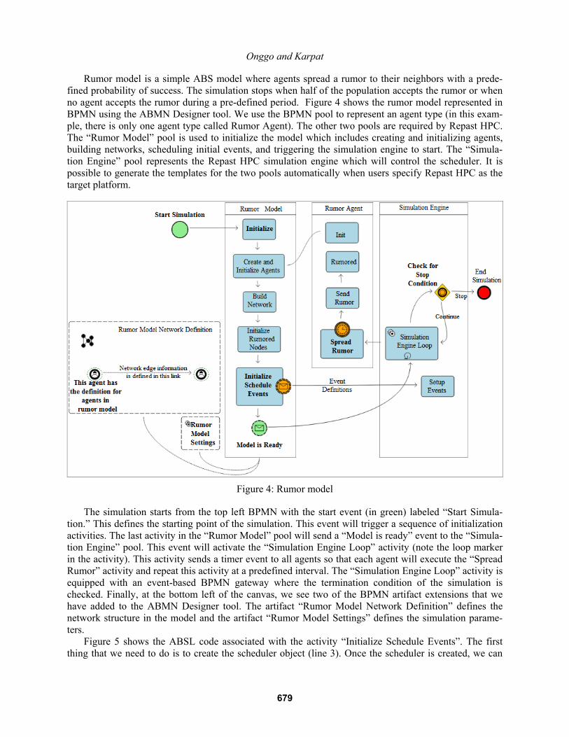
Rumor model is a simple ABS model where agents spread a rumor to their neighbors with a prede-fined probability of success. The simulation stops when half of the population accepts the rumor or when no agent accepts the rumor during a pre-defined period. Figure 4 shows the rumor model represented in BPMN using the ABMN Designer tool. We use the BPMN pool to represent an agent type (in this exam-ple, there is only one agent type called Rumor Agent). The other two pools are required by Repast HPC. The “Rumor Model” pool is used to initialize the model which includes creating and initializing agents, building networks, scheduling initial events, and triggering the simulation engine to start. The “Simula-tion Engine” pool represents the Repast HPC simulation engine which will control the scheduler. It is possible to generate the templates for the two pools automatically when users specify Repast HPC as the target platform.
Figure 4: Rumor model
The simulation starts from the top left BPMN with the start event (in green) labeled “Start Simula-tion.” This defines the starting point of the simulation. This event will trigger a sequence of initialization activities. The last activity in the “Rumor Model” pool will send a “Model is ready” event to the “Simula-tion Engine” pool. This event will activate the “Simulation Engine Loop” activity (note the loop marker in the activity). This activity sends a timer event to all agents so that each agent will execute the “Spread Rumor” activity and repeat this activity at a predefined interval. The “Simulation Engine Loop” activity is equipped with an event-based BPMN gateway where the termination condition of the simulation is checked. Finally, at the bottom left of the canvas, we see two of the BPMN artifact extensions that we have added to the ABMN Designer tool. The artifact “Rumor Model Network Definition” defines the network structure in the model and the artifact “Rumor Model Settings” defines the simulation parame-ters. Figure 5 shows the ABSL code associated with the activity “Initialize Schedule Events”. The first thing that we need to do is to create the scheduler object (line 3). Once the scheduler is created, we can
679

Onggo and Karpat
schedule events for our model. For example, in line 4, a stop event is scheduled to happen at the time that is specified by the “stop.at” variable. Lines 5 to 8 schedule events that will occur at the time specified in the second parameter and are repeated at an interval that is specified in the third parameter. The events will activate the activities specified in the last parameter. Lines 9 to 11 schedule events that will activate activities that are specified in the last parameter when the simulation ends. Figure 6 shows the generated C++ code from the ABSL shown in Figure 5. This C++ code is generated with Repast HPC as the target platform.
1. // ABSL Code for shape [name: type=BPMNTaskTypeAbstract id=shape1299668900222] 2. fInitialize_events 3. giSched_id = lABS.fiCreate_schedule () 4. lABS.fSchedule_stop (giSched_id, lABS.rGet_variable ("stop.at")) 5. lABS.fSchedule_event (giSched_id, 1, 1, fSpread_rumor) 6. lABS.fSchedule_event (giSched_id, 1.05, 1, fSynch_agents) 7. lABS.fSchedule_event (giSched_id, 1.1, 1, fDataset_record) 8. lABS.fSchedule_event (giSched_id, 25.2, 25, fDataset_write) 9. lABS.fSchedule_end_event (giSched_id, fDataset_write) 10. lABS.fSchedule_end_event (giSched_id, fRumor_model_log_rumor_sum) 11. lABS.fSchedule_end_event (giSched_id, fDataset_close) 12. fend
Figure 5: ABSL Code Associated with Activity Initialize
// ABSL Code for shape [name: type=BPMNTaskTypeAbstract id=shape1299668900222] void fInitialize_events () { giSched_id = lABS.fiCreate_schedule (); lABS.fSchedule_stop (giSched_id, lABS.rGet_variable ("stop.at")); lABS.fSchedule_event (giSched_id, 1, 1, fSpread_rumor); lABS.fSchedule_event (giSched_id, 1.05, 1, fSynch_agents); lABS.fSchedule_event (giSched_id, 1.1, 1, fDataset_record); lABS.fSchedule_event (giSched_id, 25.2, 25, fDataset_write); lABS.fSchedule_end_event (giSched_id, fDataset_write); lABS.fSchedule_end_event (giSched_id, fRumor_model_log_rumor_sum); lABS.fSchedule_end_event (giSched_id, fDataset_close); }
Figure 6: C++ Code Generated from ABSL in Figure 5
4 CONCLUSIONS AND FURTHER WORK
We have proposed the use of Business Process Model and Notation (BPMN) for agent-based simulation (ABS) conceptual model representation. BPMN is a standard designed for business users and supported by a number of major organizations. We hope the use of BPMN may promote wider adoption of ABS by business users. To demonstrate how BPMN is used to represent ABS conceptual models, we have devel-oped a Web-based visual modeling tool called ABMN Designer (Agent-based Model and Notation De-signer). ABMN Designer allows users to design an ABS model visually by clicking and dragging BPMN core elements and their extensions onto a canvas. ABMN Designer also provides a simple specification language that allows users (typically simulation modelers) to provide detailed specifications for each ele-ment in the diagram. Based on the target ABS simulation engine specified by the users, ABMN Designer can generate an executable model. We have identified three future areas of work. Firstly, we will continue the development of the soft-ware tool by adding support for more platforms and improve the design of the specification language, i.e., ABSL. Secondly, we will establish a formal proof of the general modeling power of BPMN and ABSL. Finally, we will gather feedback on the use of BPMN from business practitioners.
680
Onggo and Karpat
ACKNOWLEDGMENT
ABMN Designer is developed by Onder Karpat as part of his Master of Science degree with the Universi-ty of Liverpool and Laureate Online Education.
REFERENCES
Alan, R. J. 2010. Survey of Agent-Based Modelling and Simulation Tools. Science and Technology Facili-ties Council. Accessed March 28, 2011. http://epubs.stfc.ac.uk.
Allen, T., and N. Davis. 2010. “A Simple Agent-Based Social Impact Theory Model of Student STEM Selection.” In Proceedings of the 2010 Winter Simulation Conference, edited by B. Johansson, S. Jain, J. Montoya-Torres, J. Hugan, and E. Yücesan, 278-289. Piscataway, New Jersey: Institute of Electrical and Electronics Engineers, Inc.
Bauer, B., J. P. Müller, and J. Odell. 2001. “Agent UML: A Formalism for Specifying Multiagent Interac-tion.” In Agent-Oriented Software Engineering, edited by P. Ciancarini, and M. Wooldridge, 91-103. Berlin: Springer-Verlag.
Brailsford, S. C., S. M. Desai, and J. Viana. 2010. “Towards the Holy Grail: Combining System Dynam-ics and Discrete-Event Simulation in Healthcare.” In Proceedings of the 2010 Winter Simulation Con-ference, edited by B. Johansson, S. Jain, J. Montoya-Torres, J. Hugan, and E. Yücesan, 2293-2303. Piscataway, New Jersey: Institute of Electrical and Electronics Engineers, Inc.
Collier, N. 2010. Repast HPC Manual. Accessed March 28, 2011. http://repast.sourceforge.net/docs/RepastHPCManual.pdf.
Lacy, L. W., W. Randolph, B. Harris, S. Youngblood, J. Sheehan, R. Might, and M. Meta. 2001. “Devel-oping a Consensus Perspective on Conceptual Models for Simulation Systems.” In Proceedings of the 2001 Spring Simulation Interoperability Workshop. Accessed February 10, 2009. http://www.sisostds.org.
Macal, C. M. 2010. “To Agent-Based Simulation from System Dynamics.” In Proceedings of the 2010 Winter Simulation Conference, edited by B. Johansson, S. Jain, J. Montoya-Torres, J. Hugan, and E. Yücesan, 371-382. Piscataway, New Jersey: Institute of Electrical and Electronics Engineers, Inc.
Moldt, D., and F. Wienberg. 1997. “Multi-Agent Systems Based on Coloured Petri Nets.” In LNCS 1248: Application and theory of Petri Nets, edited by P. Azéma, and G. Balbo, 82-101. Berlin / Heidelberg: Springer.
Morecroft, J., and S. Robinson. 2006. “Comparing Discrete Event Simulation and System Dynamics: Modelling a Fishery.” In Proceedings of the 2006 OR Society Simulation Workshop, edited by S. Robinson, S. Taylor, S. Brailsford, and J. Garnett, 137-148. Birmingham, UK: OR Society.
Nance, R. E. 1994. “The Conical Methodology and the Evolution of Simulation Model Development.” Annals of operations research 53:1-45.
North, M. J., and C. M. Macal. 2007. Managing Business Complexity: Discovering Strategic Solutions with Agent-based Modeling and Simulation. Oxford, UK: Oxford University Press.
Odell, J., H. Parunak, and B. Bauer. 2000. ‘‘Extending UML for Agents.’’ In Proceedings of the Agent-Oriented Information Systems Workshop, edited by G. Wagner, Y. Lesperance, and E. Yu, pp. 3–17.
OMG (Object Management Group). 2010. Business Process Model and Notation (BPMN) version 2.0. Accessed March 28, 2011. http://www.bpmn.org.
Onggo, B. S. S. 2010. “Methods for Conceptual Model Representation.” In Conceptual Modelling for Discrete-Event Simulation, edited by S. Robinson, K. Kothiadis and R. Brooks, 337-354. New York: Academic Press.
Robinson, S. 2002. “Modes of simulation practice: Approaches to business and military simulation.” Sim-ulation Modelling Practice And Theory 10 (8):513-123.
681

Onggo and Karpat
Robinson, S. 2010. “Conceptual Modelling for Simulation: Definition and Requirements.” In Conceptual Modelling for Discrete-Event Simulation, edited by S. Robinson, K. Kothiadis, and R. Brooks, 235-256. New York: Academic Press.
Robinson, S., and M. Pidd. 1998. “Provider and Customer Expectations of Successful Simulation Pro-jects.” Journal of the Operational Research Society 49(3):200-209.
Saple, A., and L. Yilmaz. 2006. “Agent-Based Simulation Study of Behavioral Anticipation: Anticipatory Fault Management in Computer Networks.” In Proceedings of the 44th annual Southeast regional conference, 383-388. New York: ACM Press.
Schruben, L., and E. Yucesan. 1988. “Simulation Graphs.” In Proceedings of the 1988 Winter Simulation Conference, edited by M. Abrams, P. Haigh, and J. Comfort, 504-508. Piscataway, New Jersey: Insti-tute of Electrical and Electronics Engineers, Inc.
Siebers, P. O., C. M. Macal, J. Garnett, D. Buxton, and M. Pidd. 2010. “Discrete-Event Simulation is Dead, Long Live Agent-Based Simulation!” Journal of Simulation 4:204-210.
AUTHOR BIOGRAPHIES
BHAKTI SATYABUDHI STEPHAN ONGGO is a lecturer at the Department of Management Science at the Lancaster University Management School. He received his MSc in Management Science from the Lancaster University and completed his PhD in Computer Science from the National University of Singa-pore. His research interests are in the areas of simulation methodology (modeling paradigms and concep-tual modeling), simulation technology (parallel and distributed simulation) and simulation applications. His email address is [email protected]. ONDER KARPAT is a senior software developer at the OCLC organization. He is reading MSc in In-formation Systems Management at the University of Liverpool. He received his BSc in Electrical and Electronics Engineering from the Middle East Technical University, Turkey. He has in total thirteen years of R&D experience in various fields including Digital Signal Processing at TUBITAK Turkey, and com-piler development at Intel Germany. He holds a patent and has published and presented articles at a num-ber of conferences. His e-mail is [email protected].
682