Embed Size (px)
Citation preview
By:Dr. Ahmed ElShafee
Dr. Ahmed ElShafee, ACU : Fall 2015, Electronic Circuits١
Lecture (04)Diode applications,
cont.
Agenda• Full wave rectifier, cont.,..• Filters• Voltage Regulators• Diode limiters• Diode Clampers
Dr. Ahmed ElShafee, ACU : Fall 2015, Electronic Circuits٢
Bridge Full‐Wave Rectifier Operation• uses four diodes connected as shown
Dr. Ahmed ElShafee, ACU : Fall 2015, Electronic Circuits٣
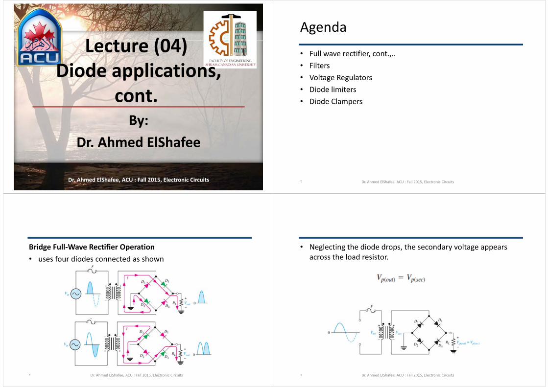
• Neglecting the diode drops, the secondary voltage appears across the load resistor.
Dr. Ahmed ElShafee, ACU : Fall 2015, Electronic Circuits٤

• two diodes are always in series with the load resistor during both the positive and negative half‐cycles. If these diode drops are taken into account, the output voltage is
Dr. Ahmed ElShafee, ACU : Fall 2015, Electronic Circuits٥
•
Dr. Ahmed ElShafee, ACU : Fall 2015, Electronic Circuits٦
0.7
0.7
• Peak Inverse Voltage• If diodes in forward bias are ideal
Dr. Ahmed ElShafee, ACU : Fall 2015, Electronic Circuits٧
• If the diode drops of the forward‐biased diodes are included
Dr. Ahmed ElShafee, ACU : Fall 2015, Electronic Circuits٨

Example 04• Determine the peak output voltage for the bridge rectifier in
Figure. Assuming the practical model, what PIV rating is required for the diodes?
• The transformer is specified to have a 17V peak secondary voltage for the standard 120 V across the primary
Dr. Ahmed ElShafee, ACU : Fall 2015, Electronic Circuits٩
•
Dr. Ahmed ElShafee, ACU : Fall 2015, Electronic Circuits١٠
power supply filters and regulators• A power supply filter ideally eliminates the fluctuations in the
output voltage of a halfwave or full‐wave rectifier and produces a constant‐level dc voltage
• Filtering is necessary because electronic circuits require a constant source of dc voltage and current to provide power and biasing for proper operation.
• Filters are implemented with capacitors,
Dr. Ahmed ElShafee, ACU : Fall 2015, Electronic Circuits١١
• The 60 Hz pulsating dc output of a half‐wave rectifier or the 120 Hz pulsating output of a full‐wave rectifier
Dr. Ahmed ElShafee, ACU : Fall 2015, Electronic Circuits١٢

• Figure shows filtering concept giving a nearly smooth dc output voltage from the filter.
• The small amount of fluctuation in the filter output voltage is called ripple.
Dr. Ahmed ElShafee, ACU : Fall 2015, Electronic Circuits١٣
• Capacitor‐Input Filter• During the positive first quarter‐cycle of the input, the diode
is forward‐biased, allowing the capacitor to charge to within 0.7 V of the input peak
Dr. Ahmed ElShafee, ACU : Fall 2015, Electronic Circuits١٤
• When the input begins to decrease below its peak,, the capacitor retains its charge and the diode becomes reverse‐biased because the cathode is more positive than the anode.
• During the remaining part of the cycle, the capacitor can discharge only through the load resistance at a rate determined by the RLC time constant, which is normally long compared to the period of the input.
• The larger the time constant, the less the capacitor will discharge.
Dr. Ahmed ElShafee, ACU : Fall 2015, Electronic Circuits١٥
• During the first quarter of the next cycle, as illustrated , the diode will again become forward‐biased when the input voltage exceeds the capacitor voltage by approximately 0.7 V.
Dr. Ahmed ElShafee, ACU : Fall 2015, Electronic Circuits١٦

• Ripple Voltage• The variation in the capacitor voltage due to the charging and
discharging is called the ripple voltage
Dr. Ahmed ElShafee, ACU : Fall 2015, Electronic Circuits١٧
• a full‐wave rectifier is twice that of a half‐wave rectifier, easier to filter because of the shorter time between peaks.
Dr. Ahmed ElShafee, ACU : Fall 2015, Electronic Circuits١٨
• Ripple Factor The ripple factor (r) is an indication of the effectiveness of the filter and is defined as
• where Vr(pp) is the peak‐to‐peak ripple voltage and VDC is the dc (average) value of the filter’s output voltage,
Dr. Ahmed ElShafee, ACU : Fall 2015, Electronic Circuits١٩
• For a full‐wave rectifier with a capacitor‐input filter
Dr. Ahmed ElShafee, ACU : Fall 2015, Electronic Circuits٢٠

Example 05• Determine the ripple factor for the filtered bridge rectifier
with a load as indicated in Figure
Dr. Ahmed ElShafee, ACU : Fall 2015, Electronic Circuits٢١
•
Dr. Ahmed ElShafee, ACU : Fall 2015, Electronic Circuits٢٢
• Surge Current in the Capacitor‐Input Filter• At the instant the switch is closed, voltage is connected to the
bridge and the uncharged capacitor appears as a short• This produces an initial surge of current, Isurge,
Dr. Ahmed ElShafee, ACU : Fall 2015, Electronic Circuits٢٣
• The worst‐case situation occurs when the switch is closed at a peak of the secondary voltage and a maximum surge current, Isurge(max),
• A fuse is generally used because of the surge current that initially occurs when power is first turned on.
• The fuse rating is determined by power calculation.• in an ideal transformer Pin = Pout
• The fuse rating should be at least 20% larger than the calculated value of Ipri.
Dr. Ahmed ElShafee, ACU : Fall 2015, Electronic Circuits٢٤
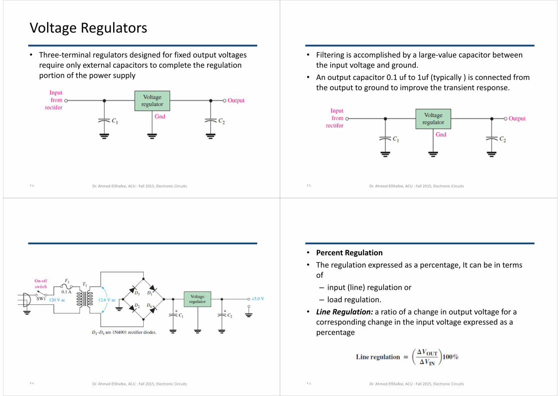
Voltage Regulators• Three‐terminal regulators designed for fixed output voltages
require only external capacitors to complete the regulation portion of the power supply
Dr. Ahmed ElShafee, ACU : Fall 2015, Electronic Circuits٢٥
• Filtering is accomplished by a large‐value capacitor between the input voltage and ground.
• An output capacitor 0.1 uf to 1uf (typically ) is connected from the output to ground to improve the transient response.
Dr. Ahmed ElShafee, ACU : Fall 2015, Electronic Circuits٢٦
Dr. Ahmed ElShafee, ACU : Fall 2015, Electronic Circuits٢٧
• Percent Regulation• The regulation expressed as a percentage, It can be in terms
of – input (line) regulation or – load regulation.
• Line Regulation: a ratio of a change in output voltage for a corresponding change in the input voltage expressed as a percentage
Dr. Ahmed ElShafee, ACU : Fall 2015, Electronic Circuits٢٨

• Load Regulation: how much change occurs in the output voltage over a certain range of load current values,
• from minimum current (no load, NL) to maximum current (full load, FL).
Dr. Ahmed ElShafee, ACU : Fall 2015, Electronic Circuits٢٩
Example 06• A certain 7805 regulator has a measured no‐load output
voltage of 5.18 V and a fullload output of 5.15 V. What is the load regulation expressed as a percentage
Dr. Ahmed ElShafee, ACU : Fall 2015, Electronic Circuits٣٠
• A certain 7805 regulator has a measured no‐load output voltage of 5.18 V and a fullload output of 5.15 V. What is the load regulation expressed as a percentage
Dr. Ahmed ElShafee, ACU : Fall 2015, Electronic Circuits٣١
Diode limiters• Figure shows a diode positive limiter (also called clipper) that
limits or clips the positive part of the input voltage.• As the input voltage goes positive, the diode becomes
forward biased and conducts current. • Point A is limited to +0.7 V when the input voltage exceeds
this value
Dr. Ahmed ElShafee, ACU : Fall 2015, Electronic Circuits٣٢

• When the input voltage goes back below 0.7 V, the diode is reverse‐biased and appears as an open.
• If R1 is small compared to R1, then Vout=Vin ٣٣
Example• What would you expect to see displayed on an oscilloscope
connected across RL in the limiter shown in Figure
Dr. Ahmed ElShafee, ACU : Fall 2015, Electronic Circuits٣٤
•
Dr. Ahmed ElShafee, ACU : Fall 2015, Electronic Circuits٣٥
• Biased Limiters• The voltage at point A must equal VBIAS + 0.7 V before the
diode will become forward‐biased and conduct.
Dr. Ahmed ElShafee, ACU : Fall 2015, Electronic Circuits٣٦
•
Dr. Ahmed ElShafee, ACU : Fall 2015, Electronic Circuits٣٧
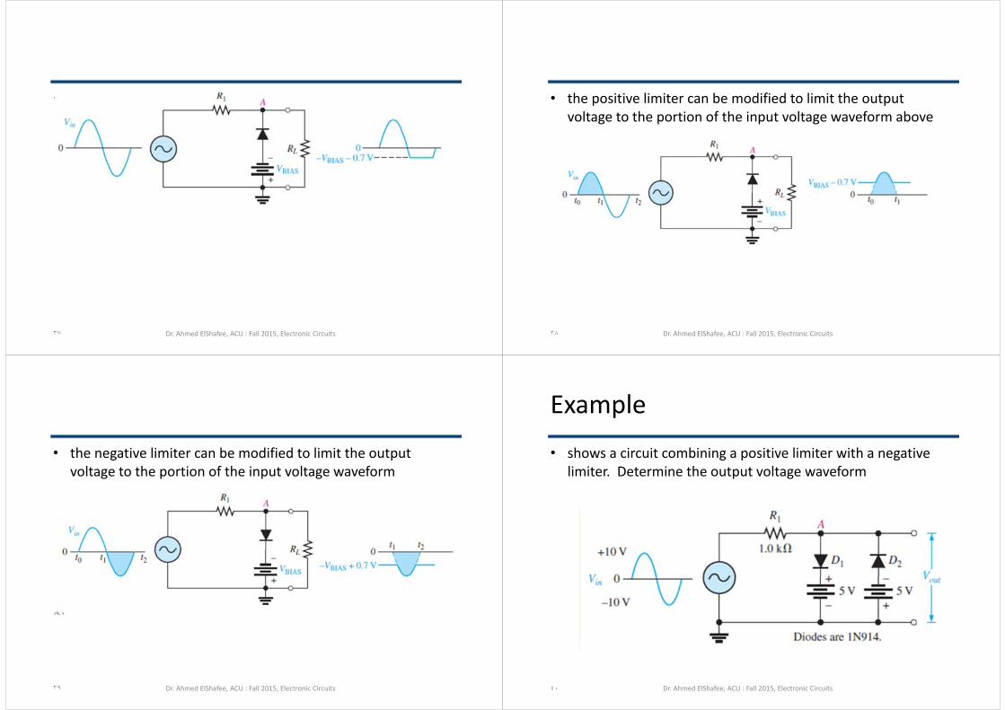
• the positive limiter can be modified to limit the output voltage to the portion of the input voltage waveform above
Dr. Ahmed ElShafee, ACU : Fall 2015, Electronic Circuits٣٨
• the negative limiter can be modified to limit the output voltage to the portion of the input voltage waveform
Dr. Ahmed ElShafee, ACU : Fall 2015, Electronic Circuits٣٩
Example• shows a circuit combining a positive limiter with a negative
limiter. Determine the output voltage waveform
Dr. Ahmed ElShafee, ACU : Fall 2015, Electronic Circuits٤٠

•
Dr. Ahmed ElShafee, ACU : Fall 2015, Electronic Circuits٤١
• Voltage‐Divider Bias
Dr. Ahmed ElShafee, ACU : Fall 2015, Electronic Circuits٤٢
• A Limiter Application• almost all digital circuits should not have an input level that
exceeds the power supply voltage. An input of a few volts more than this could damage the circuit.
• To prevent the input from exceeding a specific level, you may see a diode limiter across the input signal path in many digital circuits.
Dr. Ahmed ElShafee, ACU : Fall 2015, Electronic Circuits٤٣
Example• Describe the output voltage waveform for the diode limiter in
Figure
Dr. Ahmed ElShafee, ACU : Fall 2015, Electronic Circuits٤٤
•
Dr. Ahmed ElShafee, ACU : Fall 2015, Electronic Circuits٤٥
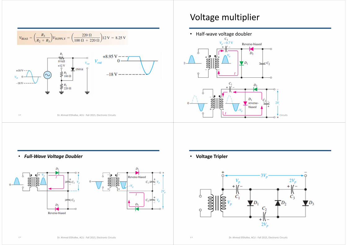
Voltage multiplier• Half‐wave voltage doubler
Dr. Ahmed ElShafee, ACU : Fall 2015, Electronic Circuits٤٦
• Full‐Wave Voltage Doubler
Dr. Ahmed ElShafee, ACU : Fall 2015, Electronic Circuits٤٧
• Voltage Tripler
Dr. Ahmed ElShafee, ACU : Fall 2015, Electronic Circuits٤٨
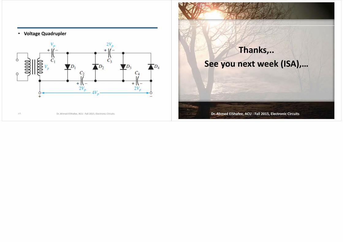
• Voltage Quadrupler
Dr. Ahmed ElShafee, ACU : Fall 2015, Electronic Circuits٤٩
Thanks,..See you next week (ISA),…
Dr. Ahmed ElShafee, ACU : Fall 2015, Electronic Circuits٥٠