Embed Size (px)
Citation preview

Control slag – stabilize your process Agellis
2
Introduction
Product presentation
How does it work?
1
2
3
4
5
Agenda – Slag detection for furnaces
Examples
Case study results

3
From the furnace to the caster
1. Introduction
Agellis solutions in the process flow

4
Overview technology platformsElectromagnetic and Vision
1. Introduction

5
IMPACT OF SLAG CONTROL ON SECONDARY STEELMAKING PROCESS
Electromagnetic slag detection for furnace
1. Introduction

6
▪ To minimize slag carryover -> early detection
▪ To monitor the entire tapping stream -> vortex
▪ To work flawlessly with flames and fumes
▪ To work with any steel, alloys and metal grades
▪ To be easy to use and maintain
▪ To calculate slag transfer amounts
EMLI-FurnaceSlag
What is the system engineered for?
2. Product presentation

7
▪ By stabilizing the slag carry over amount
➢Minimized variations of the pre-conditions in LF
➢ Avoid time losses due to unwanted deslagging operations
▪ By indicating optimal tapping stream
➢Minimized transfer of unwanted elements to LF
➢ Lower alloying additive cost
▪ Reduce tap hole wear and wear in ladles
➢Reduce costs
EMLI-FurnaceSlag
How does the system improve production?
2. Product presentation

8
▪ Non balanced sensors are installed around the tap-hole
▪ The entire tapping stream is monitored electromagnetically
▪ When a preset signal change is measured the system alarms the
operator and/or trigger a tilt back or gate closure.
▪ The signal change corresponds to slag passing the tap-hole
EMLI-FurnaceSlag
How does it work?
3. How does it work?

9
▪ A magnetic field is created around the tapping stream and continuously monitored
▪ The presence of steel affects the magnetic field greatly and slag does not
▪ The system is automatically calibrated on a full stream of steel
▪ As soon as slag appears in the stream, the magnetic field signal changes
▪ The change in the magnetic field is analyzed and related to the onset of slag in the stream
EMLI-FurnaceSlag
Principle of operation
3. How does it work?

10
EMLI-FurnaceSlag
System layout
3. How does it work?
EBT

11
▪ The sensors are specifically engineered for the furnace conditions
▪ Placed around the EBT stones during furnace reline
▪ Placed out of the way, no interference with tap-hole replacement
▪ Require no cooling and engineered to work in up to 900ºC
EMLI-FurnaceSlag
Installation of sensors
3. How does it work?

12
▪ The alarm level can be set in the system or via the plant overlaying control system
▪ The alarm level setting is not dependent of the steel grade
▪ This means, customer can adjust when the alarm should be triggered depending on tap-hole wear and hot-heel practices.
EMLI-FurnaceSlag
How does it work?
3. How does it work?

17
▪ Over a tap-hole campaign (225 charges), the tapping's where rated with the EMLI-FurnaceSlag system as “Slag tappings” or “Normal tappings”
▪ Comparing samples from EAF with LF, Manganese and Phosphorous oxides rates were studied
▪ The chart shows the changes in Phosphorous elements versus the changes in the element Manganese
EMLI-FurnaceSlag
Independent case study on 50T EAF
5. Case study

18
▪ An element reversion (reduced back to the steel), indicates a negative impact on the secondary metallurgy process
▪ It was observed that the group rated “slag tapping” had a larger reversion rate than “Normal tapping”
▪ Clear correlation between heats with detected slag tapping's and undesired element reversion
EMLI-FurnaceSlag
Independent case study on 50T EAF
5. Case study

19
▪ EMLI-FurnaceSlag system
effectively helps achieving more
reproducible taps
-> Greater production stability
▪ Used in production it is an effective
and direct operator support
indicating:
✓ Slag tapping alarm (in time!)
✓ Vortexing alarm
✓ Insufficient tapping angle
✓ Slag amount calculation index
✓ Partial openings
EMLI-FurnaceSlag
Independent case study - conclusions
5. Case study

20
CONTINUOUS CASTING
Electromagnetic slag detection for ladles
1. Introduction

21
Product presentation
How does it work?
Examples
1
2
3
4
Agenda – Slag detection for ladles
Conclusions

22
▪ To minimize slag carryover
▪ To increase production yield (all steel is transferred)
▪ To work with all steel grades
▪ To work with open and shrouded tapping
▪ To have a very high availability
▪ To be easy to use and maintain
▪ To withstand degasser conditions (high temperatures)
EMLI-LadleSlag
What is the target?
2. Product presentation

23
EMLI-LadleSlag
2. Product presentation
Technology comparison
EMLI (Heavy Duty Cassettes) Vibration
Method Direct slag measurement Indirect vibration of shroud
Steel grade Independent of steel grade Need calibration for each steel grade/slag type
Slag detected In the tap hole before sliding gate. When passing the shroud after sliding gate.
Sliding gate plate wear Reduced by typically 50% No change, same as before
Sensitivity Very good steel/slag ratio sensitivity = reliable Very low steel/slag ratio sensitivity = unreliable due to indirect and late detection
Availability Typically better than 98% Typically 70%
External influences None Many other vibrations in the caster = false alarms
Response time 0,05 Seconds (effective detection) = small slag transfer
1-4 Seconds (effective detection) = large slag transfer
Commissioning time 3-5 days 15 - 25 days or more (all steel grades need calibration)
Maintenance Sensors are changed every 2-3 years Direct cost is about 15-20 000€/caster/year + loss of availability (system non availability during maintenance).
Vacuum Degassing Yes. The sensor is not temperature sensitive Yes. The system is located at the caster.

24
EMLI-LadleSlag
2. Product presentation
Technology comparison
EMLI (Heavy Duty Cassettes) Ring shaped balanced electromagnetic sensors
Method Direct slag measurement Direct slag measurement
Steel grade Independent of steel grade Independent of steel grade
Slag detected In the tap hole high above sliding gate In the tap hole close to sliding plates
Max sensor temp 900 degrees Celsius 450 degrees Celsius
Sensitivity Steel/slag ratio sensitivity = 5-7% Steel/slag ratio sensitivity = 1-2%
Availability Better than 98% Typically 90-95% (mainly due to heat issues)
External influences None Gate movements and heat can be problematic
Response time 0,05 Seconds = small slag transfer similar= small slag transfer
Commissioning time 3-5 days 3-5 days
Maintenance Sensors are changed every 2-3 years Typically changed every year.Sensors changed more often, additional work.
Vacuum Degassing Yes. The sensor is not temperature sensitive Preferably not. Heavy wear due to elevated temperatures.

25
▪ A magnetic field is created around the tapping stream and continuously monitored
▪ The presence of steel affects the magnetic field greatly and slag does not
▪ The system is automatically calibrated on a full stream of steel
▪ As soon as slag appears in the stream, the magnetic field signal changes
▪ The change in the magnetic field is analyzed and related to the onset of slag in the stream
EMLI-LadleSlag
2. Product presentation
Electromagnetic principle of operation

26
EMLI-LadleSlag
3. How does it work?
System overview - How does it work?

27
▪ Sensors are usually installed in the ladle bottom plate
▪ No cooling is required
▪ Directional sensing above the sensors
▪ Sensors & leads are protected
▪ Long-life sensors accessible for maintenance
EMLI-LadleSlag
3. How does it work?
How does it work? – Sensors

28
EMLI-LadleSlag
3. How does it work?
How does it work? – Sensor Cassette for easy access

30
EMLI-LadleSlag
3. How does it work?
How does it work? – Ladle view from side
Connector
Example of
connector
position

31
EMLI-LadleSlag
3. How does it work?
How does it work? – Ladle view from below
Connector
Protected
High temp
leads
EMLI SIL
Sensor
Cassettes
34
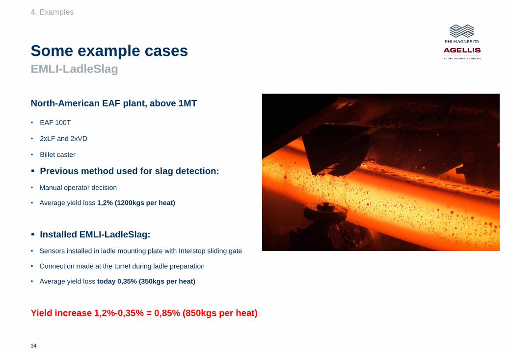
North-American EAF plant, above 1MT
• EAF 100T
• 2xLF and 2xVD
• Billet caster
▪ Previous method used for slag detection:
• Manual operator decision
• Average yield loss 1,2% (1200kgs per heat)
▪ Installed EMLI-LadleSlag:
• Sensors installed in ladle mounting plate with Interstop sliding gate
• Connection made at the turret during ladle preparation
• Average yield loss today 0,35% (350kgs per heat)
Yield increase 1,2%-0,35% = 0,85% (850kgs per heat)
EMLI-LadleSlag
Some example cases
4. Examples

35
North-American EAF plant, above 1MT
• EAF 160T
• 1xLF and 1xVD
• Bloom caster
▪ Previous method used for slag detection:
• Manual operator decision
• Average yield loss 0,95% (1500kgs per heat)
▪ Installed EMLI-LadleSlag:
• Sensors installed in ladle mounting plate (10 ladles) with Interstop sliding gate
• Connection made casting position
• Average yield loss today 0,4% (640kgs per heat)
Yield increase 0,95%-0,40% = 0,55% (880kgs per heat)
EMLI-LadleSlag
Some example cases
4. Examples
36
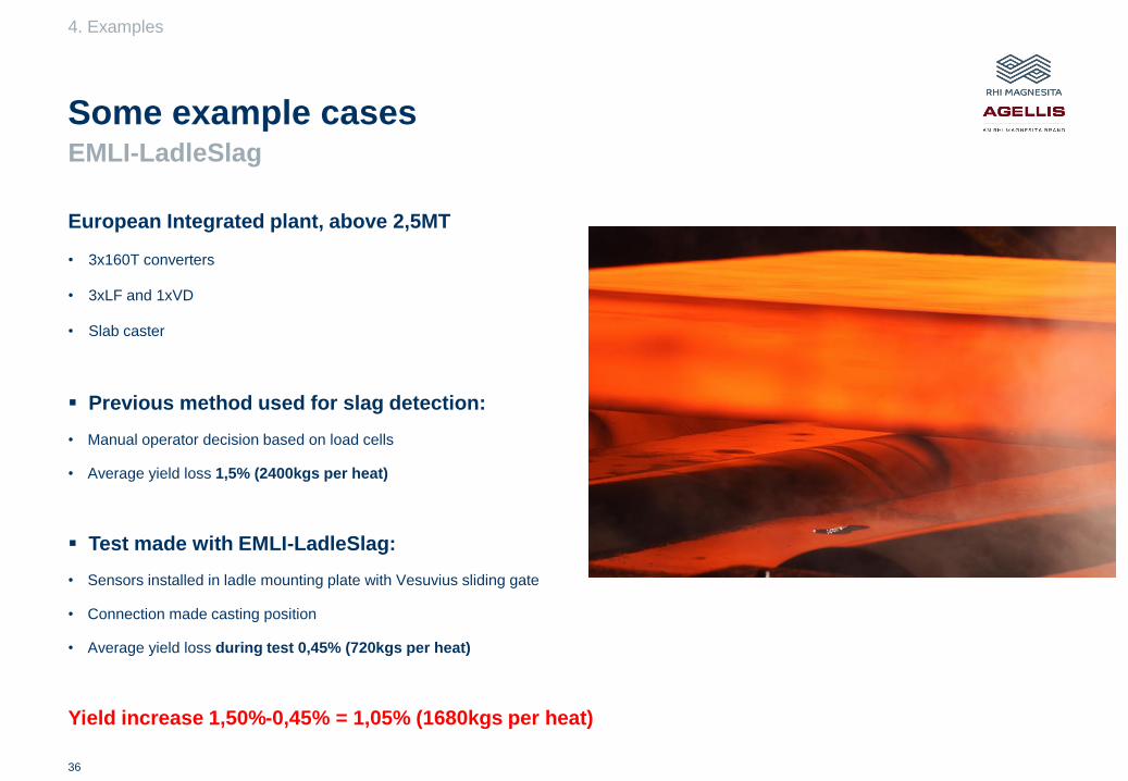
European Integrated plant, above 2,5MT
• 3x160T converters
• 3xLF and 1xVD
• Slab caster
▪ Previous method used for slag detection:
• Manual operator decision based on load cells
• Average yield loss 1,5% (2400kgs per heat)
▪ Test made with EMLI-LadleSlag:
• Sensors installed in ladle mounting plate with Vesuvius sliding gate
• Connection made casting position
• Average yield loss during test 0,45% (720kgs per heat)
Yield increase 1,50%-0,45% = 1,05% (1680kgs per heat)
EMLI-LadleSlag
Some example cases
4. Examples

37
▪ Improves yield between 0,2% – 1,1%
▪ Minimise the slag amount in the tundish
▪ Reduce ladle slide-gate plate wear
▪ Reduce tundish refractory wear
▪ Increase the casting sequence length
▪ Minimize slag in mold situations
▪ Reduction in manpower if automation is used
EMLI-LadleSlag
Some typical benefits
5. Conclusions

38
▪ Must be working every heat
▪ Must have a high slag to steel signal ratio
▪ Must be able to handle high temperatures > 500C
▪ Must be unaffected by gate movements
▪ Must be accessible for maintenance
EMLI-LadleSlag
5. conclusions
Conclusion – to be efficient

Get in Touch!
Important notice:
These materials do not constitute or form part, or all, of any offer of invitation to sell or issue,or any solicitation of any offer to purchase or subscribe for, any securities in any jurisdictionin which such solicitation, offer or sale would be unlawful, nor shall part, or all, of thesematerials form the basis of, or be relied on in connection with, any contract or investmentdecision in relation to any securities.
These materials contain forward-looking statements based on the currently held beliefs andassumptions of the management of RHI Magnesita N.V. or its affiliated companies, which areexpressed in good faith and, in their opinion, reasonable. Theses statements may beidentified by words such as “expectation” or “target” and similar expressions, or by theircontext. Forward-looking statements involve known and unknown risks, uncertainties andother factors, which may cause the actual results, financial condition, performance, orachievements of RHI Magnesita N.V. or its affiliates to differ materially from the results,financial condition, performance or achievements express or implied by such forward-lookingstatements. Given these risks, uncertainties and other factors, recipients of this documentare cautioned not to place undue reliance on these forward-looking statements. RHIMagnesita N.V. or its affiliates disclaims any obligation to update these forward-lookingstatements to reflect future events or developments.
Agellis – An RHI Magnesita Brand
Tellusgatan 15, SE-224 57
Lund, Sweden
Phone: +46 46 10 13 60
E-mail: [email protected]
www.agellis.com
www.rhimagnesita.com