Embed Size (px)
Citation preview

English 1 - 26Quick Start 2Français 27 - 52Comment utiliser 28Español 53 - 80Guia rápida 54Deutsch 81 - 106Schnellstart 82Italiano 107 - 132Guida rapida 108
133
Your dealer /Votre revendeur/Su revendedor/Ihr Händler/Vostro rivenditore
Owner's ManualManuel d’utilisation
Manual de OperaciónBedienungsanleitung
Manuale d'Uso
A510SA510G
AGATEC21 Boulevard Littré
78600 Le Mesnil le Roi - FranceTél: +33(0)1 34 93 36 31Fax: +33(0)1 34 93 35 89
AGATEC Construction Lasers2202 Redmond Rd.
Jacksonville, AR 72076Phone: 800.643.9696Fax: [email protected]
A510 -2009-0
6 V
1.0
A510S-jun2009.qxp 15/07/09 17:41 Page 133

14
16
13
15
17
20
19
18
21
22
2 14
3
12
1210
6
98
11
5
7
A510S-jun2009.qxp 15/07/09 17:41 Page 136

3
1. General information 4 1.1. Description 1.2. Safety 1.3. Specifications1.4. Laser overview1.5. Keypad overview
2. How to use the laser 72.1 Setup2.2 Automatic/Manual2.3 HI Alert 2.4 Rotation speed 2.5 Laser chalk line 2.6 Scanning2.7 Motorized mount2.8 Squaring2.9 Matching slope
3. Power 143.1 Installing alkaline batteries3.2 Using rechargeable batteries3.2 Later recharging
4. Checking and adjusting calibration 15
5. Care and handling 21
6. Accessories 226.1 Detector and troubleshooting6.2 Remote control6.3 Tripods6.4 Other accessories
7. Warranty 26
Table of contents
2
GB F E D I N FIN NL
Functions using the laser keypad
On/Off Press
Rotation speed Increase with ; decrease with
Stop rotation Press and hold until it stops
Chalk line Flip collar on head up for chalk line,
down for point
Move stationary point
or chalk line left Press
Move stationary point
or chalk line right Press
Scanning Press simultaneously on and
Increase scan angle Press (in scan mode)
Decrease scan angle Press (in scan mode)
Move left
scan or vertical alignment Press *
Move right
scan or vertical alignment Press *
H.I. Alert Press H.I.
Motorized mount mode Press simultaneously on and
(scan keys) for several seconds; all 3
LEDS will blink and 4 beeps will sound
Raise laser on mount Press (in wall mount mode) on remote
Lower laser on mount Press (in wall mount mode) on remote
Manual mode Press Man*
(slope on X axis) (bottom LED will blink)
* Functions not available in wall mount mode; exit to use these functions.
Quick start
A510S-jun2009.qxp 15/07/09 17:41 Page 2

5
A510S
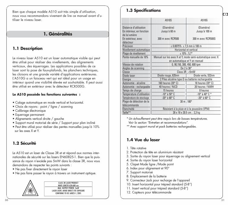
(Diameter)Up to 200 ft. (60 m)
1,000 ft. (300m) with RCR500± 3/32” at 100 ft. (± 0.0075% ± 7.5 mm at 100 m)
Horizontal and vertical± 10% ; 5.7°
Manual in both X & Y axes;also, semi-automatic mode with X in automatic, Y in manual
0, 90,150, 300, 450, 600 rpmVariable, from 2 to 36°
Class 3R; <5mW
2 D size (LR20) alkaline batteries or rechargeable batteries
A510G
(Diameter)Up to 300 ft. (100 m)
1,000 ft. (300m) with RCR500G
Red diode, 635nm Green diode, 532nm
160 hrs. at 68° F (20° C)40 hrs. / NiCD
15 hrs.14° to 122° F (-10° to 50° C)-4° to 176° F (-20° to 80° C)
18 hrs. at 68° F (20° C)20 hrs. / NiMH
8 hrs.14° to 104° F (-10° to 40° C)*-4° to 140° F (-20° to 60° C)
Recommended useInterior, depends on lightingExterior, with detectorLeveling accuracySelf-levelingLeveling range10% slope match
Rotation speedScanning angleLaser classVisible laser diodePowerBattery life – alkalineBattery life – rechargeableCharging timeOperating temperatureStorage temperatureRange of remoteEnvironmentalSize**
* In cold temperatures, warm-up may be required. See “Care and Handling” section.
** With wall mount and rechargeable battery pack
1.3 Specifications
4
GB F E D I N FIN NL
Although either model of the A510 are very simple to use, werecommend that you read this manual before operating the laser.
1.1 Description
The A510 is an automatic visible laser that can be used for level-ing, vertical alignment, plumb, and squaring. Applications includeinstalling suspended ceilings, partitions, and a variety of outdooralignment work.The A510G has a green laser beam that is ideal for using indoorswhere a high visibility beam is desired. It can also be used out-doors with the RCR500G detector.
The A510 laser has these advanced features: • Automatic self-leveling in both horizontal and vertical modes • Motorized mount speeds setup for ceilings and partitions • Manual leveling in X and Y axes for dual slope setting (± 10%)• Semi-automatic single axis slope setting (automatic leveling in X
and manual leveling in Y)• Ability to match slope for inclined planes greater than 10%• Choice of beams, including scanning and chalk line• Square shot that’s left and right adjustable• Easy electronic calibration
1.2 Safety
The A510 is a Class 3R laser, manufactured to comply with theinternational rules of safety IEC 60825-1, 2001. Although thepower of the emission of the beam is less than 5mW in Class 3R,the following cautions are recommended: • Do not stare directly at the beam • Do not set up the laser at eye level
A. CDRH warning label for USA
B. Aperture label
1. General information
CLASS 3R LASER PRODUCTWAVE LENGTH 630-680 nm
MAX. OUTPUT POWER: 5mWLASER LIGHT: AVOID DIRECT EYE EXPOSURE
CONFORMS TO IEC 60825-1; 2001COMPLIES WITH 21 CFR 1040.10 AND 1040.11
EXCEPT FOR DEVIATIONS PURSUANT TO LASER NOTICE NO. 50
DATED JULY 26, 2001AGATEC, 2202 Redmond Road
Jacksonville, AR 72076
AVOID EXPOSURE. LASER LIGHTIS EMITTED FROM THIS APERTURE
B
A
100 ft. (30 m) / 180°IP54 for water and dust resistance
11” x 7” x 8” (28 x 18 x 20.5 cm); 5.2 lbs.(2,3 kg)
A510S-jun2009.qxp 15/07/09 17:41 Page 4

2.1 Setup
The motorized wall mount and the metal head protection canboth be removed from the laser, if you wish to work withoutthese attachments.
• Horizontal
The laser can be mounted on a 5/8” tripod (10) or placeddirectly on a solid, stable surface. It can also be suspendedfrom a ceiling grid using the wall mount (see later section).
• Vertical
The laser can be mounted on a 5/8” tripod (11) or placed directlyon its back (opposite the handle) on a solid, stable surface.For more stability, we recommend you extend the motorizedmount. Use the support plate for stability when in vertical mode.
The A510 has a wide self-leveling range; however, if the laser is setup out of the leveling range, laser beam will continue to blink androtation will not start.
• Turning on the laser
Turn on the laser with the On /Off key (17). It does a self-test andthe beam blinks while the laser is self-leveling. After it’s leveled, thehead rotates. You can choose H.I. Alert mode or change to manualmode (see next section).
7
2. How to use your A510 laser
6
1.4 Laser overview
See inside front cover for photos of the laser and keypad corre-sponding to these callouts. See separate descriptions of motorizedmount, remote control, and detectors.
1. Rotating head 2. Aluminum head protection with axes indications3. Plumb or square laser beam aperture 4. Rotating laser beam aperture5. Collar to switch between point & chalk line 6. Index marks for alignment and 90°7. Motorized wall or floor mount8. Batteries 9. Jack for battery charger 10. 5/8 - 11 tripod mount for horizontal set-up11. 5/8 - 11 tripod mount for vertical set-up12. Sensors for remote control signal
1.5 Keypad overview
13. Move left: stationary point, chalk line, scan, or vertical alignment/ Move calibration beam up
14. Move right: stationary point, chalk line, scan, or vertical alignment/ Move calibration beam down
15. Decrease rotation speed or scan angle /Save calibration16. Increase rotation speed or scan angle /Change calibration axis17. On / Off 18. H.I. Alert 19. Automatic / Manual mode 20. Low battery LED / X axis calibration LED/
Indicates remote signal received21. H.I. Alert LED / Y axis calibration LED 22. Manual mode LED / Z axis calibration LED
Italics indicate keys and LEDs used in calibration mode.
GB F E D I N FIN NL
A510S-jun2009.qxp 15/07/09 17:41 Page 6
9
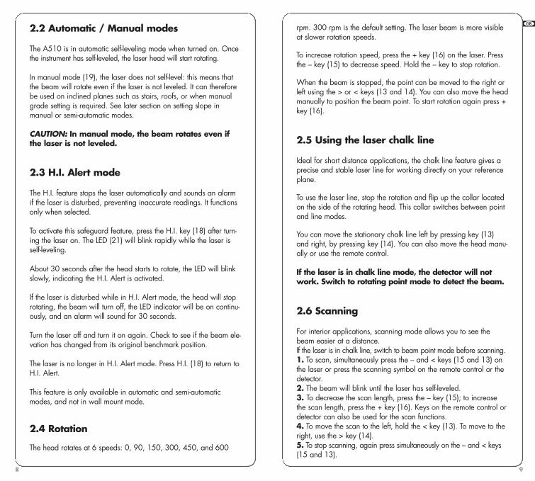
rpm. 300 rpm is the default setting. The laser beam is more visibleat slower rotation speeds.
To increase rotation speed, press the + key (16) on the laser. Pressthe – key (15) to decrease speed. Hold the – key to stop rotation.
When the beam is stopped, the point can be moved to the right orleft using the > or < keys (13 and 14). You can also move the headmanually to position the beam point. To start rotation again press +key (16).
2.5 Using the laser chalk line
Ideal for short distance applications, the chalk line feature gives aprecise and stable laser line for working directly on your referenceplane.
To use the laser line, stop the rotation and flip up the collar locatedon the side of the rotating head. This collar switches between pointand line modes.
You can move the stationary chalk line left by pressing key (13)and right, by pressing key (14). You can also move the head manu-ally or use the remote control.
If the laser is in chalk line mode, the detector will notwork. Switch to rotating point mode to detect the beam.
2.6 Scanning
For interior applications, scanning mode allows you to see thebeam easier at a distance. If the laser is in chalk line, switch to beam point mode before scanning.1. To scan, simultaneously press the – and < keys (15 and 13) onthe laser or press the scanning symbol on the remote control or thedetector. 2. The beam will blink until the laser has self-leveled. 3. To decrease the scan length, press the – key (15); to increasethe scan length, press the + key (16). Keys on the remote control ordetector can also be used for the scan functions.4. To move the scan to the left, hold the < key (13). To move to theright, use the > key (14). 5. To stop scanning, again press simultaneously on the – and < keys(15 and 13).
8
GB F E D I N FIN NL
2.2 Automatic / Manual modes
The A510 is in automatic self-leveling mode when turned on. Oncethe instrument has self-leveled, the laser head will start rotating.
In manual mode (19), the laser does not self-level: this means thatthe beam will rotate even if the laser is not leveled. It can thereforebe used on inclined planes such as stairs, roofs, or when manualgrade setting is required. See later section on setting slope in manual or semi-automatic modes.
CAUTION: In manual mode, the beam rotates even ifthe laser is not leveled.
2.3 H.I. Alert mode
The H.I. feature stops the laser automatically and sounds an alarmif the laser is disturbed, preventing inaccurate readings. It functionsonly when selected.
To activate this safeguard feature, press the H.I. key (18) after turn-ing the laser on. The LED (21) will blink rapidly while the laser isself-leveling.
About 30 seconds after the head starts to rotate, the LED will blinkslowly, indicating the H.I. Alert is activated.
If the laser is disturbed while in H.I. Alert mode, the head will stoprotating, the beam will turn off, the LED indicator will be on continu-ously, and an alarm will sound for 30 seconds.
Turn the laser off and turn it on again. Check to see if the beam ele-vation has changed from its original benchmark position.
The laser is no longer in H.I. Alert mode. Press H.I. (18) to return toH.I. Alert.
This feature is only available in automatic and semi-automaticmodes, and not in wall mount mode.
2.4 Rotation
The head rotates at 6 speeds: 0, 90, 150, 300, 450, and 600
A510S-jun2009.qxp 15/07/09 17:41 Page 8

11
Functions not availableH.I. Alert, setting slope in manual mode, or moving the scan orplumb point are not available in wall mount mode. Exit wall mountmode to use these functions.
Detaching the mountScrew both knobs (1) all the way out to detach the mount from the laser.
TroubleshootingIf the laser does not move on the mount, check that the knobs (1)are tight enough to make the power contact for the motor. Themount can also be detached to check that the contacts where thelaser and mount are fastened are clean.
2.7.2 Using the laser with wall mount on a ceiling grid
Setup:1. Check that the laser and mount are connected securely. Theknobs (1) should be turned fairly tight to make contact for themotor, although do not overtighten. Check that the safety clip is well engaged.2. Flip down the support plate (8).3. Release the clamp (2) on top of the adjustable plate (3).4. Lock the clamp against the ceiling grid. The grid should notexceed 1/8" (3mm) thickness. 5. If the foot on the support plate is not touching the wall, usethe screw (9) to adjust.
To move the laser up or down with the remote control:1. Turn on the laser and wait for it to self-level. The head mustbe rotating before you can enter wall mount mode.2. Press the scanning key and hold it for several seconds untilyou hear 4 beeps. This will put the laser in “wall mount mode”.All three LEDs will blink.3. Press the + key to move the laser up; press – to move thelaser down. Holding the key will result in fast movement; shortclicks will move the laser more precisely.If you don't raise or lower the wall mount for 5 minutes, thelaser will go back to its previous mode. You'll hear a 4-second beep.
2.7.3 Using the motorized mount and laser on the floor
1. Check that the laser and mount are connected securely. Theknobs (1) should be turned fairly tight to make contact for themotor, although do not overtighten.
10
GB F E D I N FIN NL
2.7 Motorized mount
6. Moves laser manually on mount7. Holes for attaching mount to wall8. Adjustable support for wall or ground stability 9. Screw to adjust support10. Index notches for alignment
2.7.1 Motorized mountThe motorized mount can be used to move the laser up or down ona ceiling grid. It also can be used when installing walls and partitions,to move the laser back and forth for vertical alignment. To move themount manually, use (6).
Caution: Be careful when you are in wall mount mode not to press + or –keys unless you intend to move the laser.
Maximum movementWhen the beam is at 0 on the adjustable plate, the laser can beraised a maximum of 2” (50 mm) and lowered 2.25” (60 mm).
Wait until self-leveledWhile the laser is moving on the mount, it does not self-level andthe beam continues to rotate. After moving the laser, wait a fewseconds in case it needs to self-level. Check that it’s still on the pointor level desired, and make adjustments if needed.
Automatic exit from modeIf you have not activated the wall mount for five minutes, the laserwill automatically exit from wall mount mode and return to the pre-vious mode (3 LEDs will be off and a beep will sound).
1. Attachment clamps for laser and mount 2. Clamp for ceiling grid3. Adjustable plate4. 5/8-11 tripod mount (vertical setup)5. Release for adjustable plate
1
1
102
6
9
8
4
377
5
A510S-jun2009.qxp 15/07/09 17:41 Page 10

13
For slopes up to 10%, set up the laser in horizontal mode anduse the remote to set the slope following instructions below.
For slopes greater than 10%, set up the laser in vertical modeand use the inclined plane feature (next section).
2.9.1 Semi-automatic mode 1. Set the laser over a start point. Turn the laser so that Y onthe top of the head protection faces the direction of the slope(and Y’ faces away). Sight along the Y and Y’ marks to alignthe Y axis of the laser to the second point.2. After turning the laser on and allowing it to self-level, holdthe MAN key (19) for a few seconds until the LED next to it (22)is lit continually. The laser is in manual mode in Y axis andautomatic self-leveling mode in X axis.3. You can use the H.I. Alert (18) safeguard function on the Xaxis while the Y is on manual.4. Press < (13) to match a positive slope in Y and > (14 ) to seta negative slope; the X axis will stay level.
Press twice on the Man key to return to the automatic mode.
2.9.2 Manual mode1. Set the laser over a start point. Turn the laser so that X onthe top of the head protection faces the direction of the slope(and X’ faces away). Sight along the X and X’ marks to alignthe X axis of the laser to the second point.2. After turning the laser on and allowing it to self-level, pressthe MAN key (19). The LED next to it (22) will blink, indicatingyou’re in manual mode and can match slope in the X axis. Thehead will start rotating.3. Press < (13) on the keypad to set a positive slope in X and >(14) to set a negative slope.4. To switch to the Y axis, press the H.I. key. Both LEDs (21 and22) will blink, indicating you’re in manual mode and can matchslope in the Y axis.
Note: The Y axis grade will be at a 90 degree anglefrom the X axis grade output.
5. Press < (13) to match a positive slope in Y and > (14) to seta negative slope.6. Press the MAN key to return to automatic mode.
IMPORTANT: In manual mode, the head will rotateeven if the laser is not leveled. The H.I. Alert function is not available when your laser is in manual mode.
12
GB F E D I N FIN NL
2. Flip down the support plate (8) and place the laser in verti-cal mode on the floor.3. If the support plate is not level, use the screw (9) to adjust.4. Press the scanning keys (15 and 13) and hold them for afew seconds until you hear 4 beeps. This will put the laser in“wall mount mode”. All three LEDs will blink.5. Press the + or – keys to move the laser back and forth.Holding the key will result in fast movement; short clicks willmove the laser more precisely.If you don't move the mount for 5 minutes, the laser will goback to its previous mode. You'll hear a 4-second beep.
2.8 Squaring
After placing the laser in vertical position, the plumb beam out thetop of the head can be moved to the left or right. This is necessaryto do squaring for installing walls and partitions.
To position the rotating plane perpendicular to a reference line:
1. Place the laser on the ground so that the index notch on top ofthe adjustable plate is over your reference point. 2. After the laser has self-leveled, stop the head rotation. Turn thehead down so that the beam is on the adjustable plate.3. Hold the scan key several seconds to put in wall mount mode.Use the < or > keys (13 and 14) to adjust the laser so that thebeam is on the reference point. 4. Exit from wall mount mode using the scan key. Align the beamprojecting from the top of the head to your second reference pointusing the < or > keys (13 or 14). This beam is 90° or square to theother vertical plane beam. 5. Start rotation of the head.
It is very important to check while you are using thelaser that it has not been moved and that your settingis still accurate.
2.9 Manual slope
The A510 can be used to set a manual slope on both X and Y axes.
Two modes are available• Complete manual mode: X and Y axis will be both manual• Semi-automatic mode: X in automatic / Y in manual
A510S-jun2009.qxp 15/07/09 17:41 Page 12
15
For the A510G, which has a universal charger: Select the correctpower plug adapter for your country, attach to the charger, andplug it into a 110V or 220V AC outlet. Charging time is 8 hours.
3.3 Later recharging
The laser can be charged when working, if electricity is availableon the jobsite. Simply plug in the charger and keep on working.You can also remove the battery pack to charge it, and replace itwith the alkaline battery compartment to keep on working.
The A510S has a NiCd rechargeable battery. For optimum life ofthe battery, it is recommended to charge the battery after fully discharged. To assure battery life, do not charge over 20 hours.
The A510G has a NiMH rechargeable battery, with an electroniccontrol to prevent overcharging.
The battery and the charger can be damaged if damp. Alwaysstore and charge your laser in a dry and covered place.
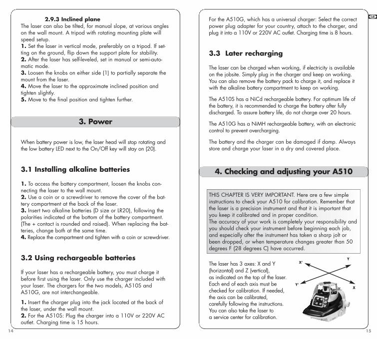
THIS CHAPTER IS VERY IMPORTANT. Here are a few simpleinstructions to check your A510 for calibration. Remember thatthe laser is a precision instrument and that it is important thatyou keep it calibrated and in proper condition.The accuracy of your work is completely your responsibility andyou should check your instrument before beginning each job,and especially after the instrument has taken a sharp jolt orbeen dropped, or when temperature changes greater than 50degrees F (28 degrees C) have occurred.
The laser has 3 axes: X and Y (horizontal) and Z (vertical), as indicated on the top of the laser.Each end of each axis must bechecked for calibration. If needed,the axis can be calibrated, carefully following the instructions. You can also take the laser toa service center for calibration.
4. Checking and adjusting your A510
14
GB F E D I N FIN NL
2.9.3 Inclined planeThe laser can also be tilted, for manual slope, at various angleson the wall mount. A tripod with rotating mounting plate willspeed setup.1. Set the laser in vertical mode, preferably on a tripod. If set-ting on the ground, flip down the support plate for stability. 2. After the laser has self-leveled, set in manual or semi-auto-matic mode.3. Loosen the knobs on either side (1) to partially separate themount from the laser.4. Move the laser to the approximate inclined position andtighten slightly.5. Move to the final position and tighten further.
When battery power is low, the laser head will stop rotating andthe low battery LED next to the On/Off key will stay on (20).
3.1 Installing alkaline batteries
1. To access the battery compartment, loosen the knobs con-necting the laser to the wall mount. 2. Use a coin or a screwdriver to remove the cover of the bat-tery compartment at the back of the laser. 3. Insert two alkaline batteries (D size or LR20), following thepolarities indicated at the bottom of the battery compartment.(The + contact is rounded and raised). When replacing the bat-teries, change both at the same time.4. Replace the compartment and tighten with a coin or screwdriver.
3.2 Using rechargeable batteries
If your laser has a rechargeable battery, you must charge itbefore first using the laser. Only use the charger included withyour laser. The chargers for the two models, A510S andA510G, are not interchangeable.
1. Insert the charger plug into the jack located at the back ofthe laser, under the wall mount. 2. For the A510S: Plug the charger into a 110V or 220V ACoutlet. Charging time is 15 hours.
3. Power
Y
X
X’
Y’
A510S-jun2009.qxp 15/07/09 17:41 Page 14

17
the beam a very small amount (1/32" at 150' or 1mm at 100meters). After pressing the key, the LED will blink rapidly as thelaser reacts. Wait until the LED returns to a slow blink to proceed.
4.2 Checking X axis
1. Place the laser on a flat surface or tripod 100 ft. (30 m)away from a wall. Position so that X’ (noted on top of laser) isfacing the wall.2. Turn on the laser.3. Mark the location of the center of the beam. If it’s too brightto see the beam, use a detector, or put in scan mode.4. Rotate the laser 180 degrees so that X faces the wall.5. Mark the location of the center of the beam near the firstmark so that both marks are in line, one above the other.6. At 100 ft., the marks should be no more than 3/16” apart(at 30m, no more than 5mm apart). This is within the statedaccuracy of ± 3/32” at 100 ft. (± 0.0075%).7. If the marks are close enough, X axis is within calibration.The second axis (Y) must then be checked (see later section).
If the marks are not close enough, the X axis needs to be cali-brated.
4.3 Calibrating X axis
The laser must be calibrated to bring the beam to the center ofthe two X marks.Read "Calibration Overview" before proceeding.
1. Turn off the laser. 2. While keeping “Man” (19) pressed, turn on the laser (17).3. After the 3 LEDs blink in sequence, release Man key. 4. The X LED (20) will blink rapidly for a bit and then slowly, indicating it’s ready to be calibrated in X axis. 5. If you have not moved the laser, use the X marks made in previous steps of “Checking X axis”. If you need a rotatingbeam for the detector, press the scan key.6. Use the arrow keys to move the beam up or down to thehalfway mark. If the X axis is toward the wall with the marks,use the < key (13) to raise the beam, and the > key (14) tolower the beam. (If X’ faces the wall, the movement is theopposite).
16
GB F E D I N FIN NL
Check and calibrate in this order:
Check both sides of X axis.• If X is within spec, proceed to check both sides of Y.• If X needs calibration, calibrate X
Check both sides of Y axis.• If Y is within spec, proceed to final X to Y check• If Y needs calibration, calibrate Y; proceed to X to Y check
Final X to Y check: compare X, X’, Y, Y’
Check Z and calibrate if necessary.
4.1 Calibration overview
Calibration is electronic, using the TL25 remote control or thedetector. The keypad of the laser may also be used, but it will take
longer due to the laser making self-adjustments during movement.
If the beam is visible, calibrate using the non-rotating point. If it’stoo bright to see the beam, you’ll use the detector and will need tohave the beam rotating. When you’re in calibration mode, pressthe scan key on the detector to rotate the beam.
The axis LED should blink slowly when in calibration mode. Whenthe laser is self-leveling or making an adjustment, the LED will blinkrapidly.
IMPORTANT:When pressing an arrow key to move the beam for calibration, useshort, rapid clicks. Do not hold the key down. One click will move
A510S-jun2009.qxp 15/07/09 17:41 Page 16

19
6. Use the arrow keys to move the beam up or down to thehalfway mark. If the Y axis is toward the wall with the marks,use the < key (13) to raise the beam, and the > key (14) tolower the beam.
7. After completing the Y calibration, press the – or . key (15)to save the calibration you have just made on Y axis. The laserwill shut off. If you are not sure of the calibration and do notwish to save it, turn the laser off with the On/Off key.
4.6 Final X to Y Check
As a final check of the horizontal axes, compare X and Y axesto be sure that your adjusted calibration is within the specs of+/- 3/32". The marks for X, X’, Y, and Y’ should be no morethan 3/16” apart at 100 ft. (5mm at 30m). If X and Y are with-in spec, proceed to checking Z axis.
4.7 Checking Z axis
1. Place the laser in vertical mode on a solid, stable surfaceabout 20 ft. away from a plumb line (plumb bob or heavyobject hanging on a string, at least 8 ft. high). You will be com-paring the rotating beam to the plumb line. If you need to cali-brate, the beam will be easier to see in a darkened room.2. Use the support plate (8) for stability.3. Turn on the laser.4. Use either scan or rotation mode. Using the scanning beamis easier, but if you cannot see the beam, work in rotation modewith a detector. 5. Move the scan to the wall over the plumb line, sliding thelaser left or right to line up the beam over the plumb line. If inrotation mode, use the < or > keys (13 or 14) to move thebeam.6. Move the scan up and down the entire length of the plumbline. If the beam is slanted, and not vertical like the plumb line,the Z axis needs to be calibrated.
4.8 Calibrating Z axis
The laser must be calibrated to bring the rotating Z beam paral-lel to the plumb line.
18
GB F E D I N FIN NL
7. After completing the X calibration, press the + or >>I key (16)to change the axis and to calibrate the Y axis. When the Y LEDblinks slowly, the laser is ready to be calibrated on the Y axis.
8. If the Y axis does not have to be calibrated, press the – or .key (15) to save the calibration you have just made on X axis.The laser will shut off. If you are not sure of the calibration anddo not wish to save it, turn the laser off with the On/Off key.
4.4 Checking Y axis
1. Rotate the laser 90 degrees so that Y’ is facing the wall. 2. Mark the location of the center of the beam.3. Rotate the laser 180 degrees so that Y faces the wall.4. Mark the location of the beam center near the first mark.5. At 100 ft., the marks should be no more than 3/16” apart(at 30m, no more than 5mm apart). This is within the statedaccuracy of ± 3/32” at 100 ft. (± 0.0075%).6. If the marks are close enough, Y axis is within calibration. Proceed to “Final X to Y Check.” If the marks are not closeenough, Y axis needs to be calibrated.
4.5 Calibrating Y axis
The laser must be calibrated to bring the beam to the center of thetwo Y marks. Read "Calibration Overview" before proceeding.
If you are still in calibration mode from the X axis, press the +or >>I key (16) to change to the Y axis. When the Y LED (21)blinks slowly, it’s ready to be calibrated in Y axis.
If you’re no longer in calibration mode:
1. Turn off the laser. 2. While keeping “Man” (19) pressed, turn on the laser (17).3. After the 3 LEDs blink in sequence, release Man key. 4. The X LED (20) will blink.5. Press the + or >>I key (16) to change to Y axis. Y LED (21)will blink rapidly for a bit and then slowly, indicating it’s readyto be calibrated in Y axis. If you have not moved the laser, use the Y marks made in previ-ous steps of “Checking Y axis”.
A510S-jun2009.qxp 15/07/09 17:41 Page 18

21
CAUTION Using of controls or adjustments of procedures other than thosespecified herein may result in hazardous radiation exposure.
The A510 is a precision instrument which must be handled withcare. Avoid shock and vibrations. Always store and transportthe laser and its accessories in the carrying case.Although weather resistant, you must always keep your laserand its accessories dry and clean after using. This will increasethe battery life.
Do not store your instrument in its case if the instrument or thecase are wet, to avoid water condensation inside the instru-ment. To maintain the precision of your A510, check and adjustit regularly.
Keep the lenses of the apertures dry and clean. Use a soft clothand glass cleaner to clean them.
Handling tips for the A510S:Do not store your laser at temperatures below -4°F (-20°C) orabove 176°F (80°C).
We recommend regular charging of the NiCd batteries in theA510S. Charge them only when they are out of power orbecoming so. Charging the A510S batteries when they are stillusable will shorten their capacity.
Handling tips for the A510G:Do not store your laser at temperatures below -4°F (-20°C) orabove 140°F (60°C).
In cold temperatures, warm-up may be required. If you areusing the laser when temperatures are between 14° and 32° F(-10° and 0° C), the laser beam will be visible within 10 to 12minutes, and will reach full power within 20 to 25 minutes.
5. Care and Handling
20
GB F E D I N FIN NL
1. Turn off the laser (17). 2. While keeping “Man” (19) pressed, turn on the laser (17).3. After the 3 LEDs blink in sequence, release Man key. 4. The Z LED (22) will blink rapidly for a bit and then slowly,indicating it’s ready to be calibrated in Z axis. The beam willnot be rotating.When it’s in calibration mode, rotate the beam by pressing thescan key, and make these adjustments:1. Use the < and > keys (13 and 14) until the beam is perfectlyvertical and parallel to the plumb line.2. Move the beam slightly so that the beam is over the plumbline for the final check. 3. After completing the Z calibration, press the – or . key (15)to save it. The laser will shut off. If you are not sure of the cali-bration and do not wish to save it, turn the laser off with theOn/Off key.
4.9 Cone error checking
1. Set up the laser about 2 feet (60 cm) away from a wall (A)or a pole and 100 feet (30 m) from another wall or pole (B).2. Turn the laser on.3. After it has self-leveled, stop the rotation and mark the loca-tion of the beam (center of the beam) on the near wall (A). Usea detector if ambient conditions are too bright. 4. Rotate the laser 180°. Mark the location of the center of thebeam on the far wall (B).5. Set up the laser about 2 feet (60 cm) away from the farwall. After the laser has self leveled, line up the beam near theprevious mark (B), and make a new mark (B').6. Mark the location of the beam (A’) on the other wall near thefirst mark (A) using the detector if necessary.7. Compare the two sets of marks on the wall. If the differencebetween AA’-BB’ exceeds 3/16" (5mm), contact your local service center.
A510S-jun2009.qxp 15/07/09 17:41 Page 20

Choice of sound level
Move square
shot to the left
Move square
shot to the right
Aim scanning left
Aim scanning rightChoice of accuracy
On/Off
• Upper Keypad
Detector mode (red keys) Remote mode Scanning mode
• Lower Keypad
Increase rotation speed
Decrease rotation speed
Start/Stop scanning mode
Calibration section of manual explainsfunction of secondary small symbols.
Increase scanning angle
Decrease scanning angle
Remote mode Scanning mode
6.1 Combination detector and laser remote control
With the A510S, use the RCR500 detector; with the A510G, usethe RCR500G. For grade rod or handheld applications. Also canuse the magnet mount to attach to metal studs for exterior curtainwall alignment or to ceiling grids for acoustical ceiling leveling.
LCD screen (front)
On-grade alignment notch
Detectionwindow
Magnet Window for remote’sinfrared signal
Level vial
6. Accessories
LCD screen(rear)
Bubble vial to
plumb rod
9V battery compartment (follow polarity
indications inside)Use a coin to unscrew
the battery cap
Turn to attachclamp todetector
Turn to tightenor remove clampfrom rod
23
TROUBLESHOOTING
• Before using a detector, it is very important to setthe A510 in point mode. The receiver cannotdetect the beam in chalk line mode.• If you cannot pick up the beam with the detector,check how you are lined up with the laser. One ofthe head protection supports on the laser may beblocking the beam; move to the left or right toreceive the beam.• The metal head protection can be removed fromthe laser by pivoting the two security locks. This willnot affect the performance or the water or dustresistance of the laser.• If it’s cold and there is no signal from the A510G,allow some warm-up time (see Care and Handlingsection).
and are used for calibration orto set manual grade
22
GB F E D I N FIN NL
A510S-jun2009.qxp 15/07/09 17:41 Page 22

Low battery
Blinking: Normal volume
Solid: Loud
No horn: Mute
Standard(Default mode)
Fine
Low
Near grade low
On-grade
Near grade high
HighBATTERY STATUS
SOUND
ACCURACY
• LCD Display
• Detection mode
1. Press the On/Off key to turn on the detector.2. Press the middle key to select the accuracy (deadband).3. Press the top key to select the sound level.4. Turn the detection window towards the laser beam, and movethe detector up or down according to the information given onthe LCD display. There are 5 channels of information, or gradeindicators.
A down arrow indicates you must move the detector down toreach the laser reference; an up arrow, move it up. When a hor-izontal line appears on the display, the detector is at the samelevel as the laser beam.
5. Press the On/Off key to turn the detector off. It will automati-cally shut off after 10 minutes if not used (and give a warningbeep).6. Keep the detection window clean, using a soft cloth and glasscleaner.
• Remote control mode
The detection mode has to be stopped to use the remote controlmode.
2524
GB F E D I N FIN NL
The remote can be used to stop or start rotation, increase ordecrease rotation speed, and move the beam or square shot. It alsocontrols scanning and electronic calibration.
• Specifications
Range* 500 ft. (150 m) in detection mode100 ft. (30 m) in remote mode
Accuracy* Fine ± <1/16" (1 mm)Standard ± 1/8” (2.5 mm)
Battery life 50 hours; 9V alkalineEnvironmental Waterproof (IP66)Size 6” x 3.25” x 1.5”; 10 oz**
(15 x 8 x 3.5 cm / 280 g**)* Varies with laser used. Actual accuracy depends on beam diameter and distance to the laser.**With batteries
6.2 Remote control
Beam or chalk line mode1.2. Decrease rotationspeed3. Increase rotationspeed4. Move stationary pointor square shot left5. Move stationary pointor square shot lright
Scanning1. Scan On / Off2. Decrease scan length
3. Increase scan length
4. Move scan left
5. Move scan right
Motorized Mount1. Press 3 seconds toactivate wall mount2. Move laser up3. Move laser down
Remote window
AA Battery
2
3
5
4
1
A510S-jun2009.qxp 15/07/09 17:41 Page 24

A510S / A510GManuel d’utilisation
26
You cannot move the scan, plumb point, or slope in wall mountmode. Exit this mode to use keys 4 & 5 for these functions. The remote control can also be used for calibrating.
To open the battery compartment and change the battery, pushthe battery cover in the direction of the arrow.
6.3 Tripods
The laser can be mounted on a 5/8-11 flat head tripod. Youcan also use a tripod with an elevating column to adjust theheight of the laser.
6.4 Other accessories
1. Laser-enhancing glasses improve the visibility of the laserbeam in bright light conditions. 2. Magnetic target improves the visibility of the laser beam inbright conditions. Quickly attaches to any metallic surface.
The A510 comes with a two-year warranty from Agatec (in North America, one year, with warranty to two years withonline or mail-in registration within 45 days of purchase). More information can be found at: www.agatec.com
7. Warranty
A510S-jun2009.qxp 15/07/09 17:41 Page 26

29
1. Généralités 30 1.1 Description1.2 Sécurité1.3 Spécifications1.4 Vue1.5 Vue du clavier
2. Utilisation du A510 322.1 Mise en station 2.2 Fonction Man2.3 Fonction Tilt2.4 Vitesse de rotation2.5 Ligne Laser2.6 Scanning2.7 Support motorisé2.8 Equerrage2.9 Pente manuelle
3. Alimentation 393.1 Installer les batteries3.2 Remplacer les piles alcalines3.3 Utiliser les batteries rechargeables3.4 Recharger les batteries
4. Vérifier et calibrer le A510 41 4.1 Contrôle et calibrage horizontal4.2 Contrôle et calibrage vertical4.3 Contrôle d’erreur conique
5. Entretien et recommandations 45
6. Accessoires 46 6.1 Cellule de détection 6.2 Télécommande6.3 Trépied6.4 Autres accessoires
7. Garantie 52
Sommaire
28
GB F E D I N FIN NL
Mettre le A510 en marche appuyer sur Vitesse de rotation augmenter avec , diminuer avec Arrêter la rotation appuyer sur jusqu’à l’arrêt de la tête Passer en ligne basculer le clapet en position haute sur la têteDéplacer à gauche point ou ligne : appuyer sur Déplacer à droite point ou ligne : appuyer sur Démarrer le mode scanning sur l’A510 appuyer simultanément sur et sur la TL25 appuyer sur Augmenter angle scanning sur l’A510 appuyer sur quand le laser est en
mode scanningsur la TL25 appuyer sur Diminuer l’angle de scanning sur l’A510 appuyer sur quand le laser est en
mode scanningsur la TL25 appuyer sur Déplacer à gauche scan ou alignement vertical : appuyer sur Déplacer à droite scan ou alignement vertical : appuyer sur Activer la fonction H.I. appuyer sur H.I.Activer le mode manuel appuyer sur Man , (axe X) led à droite de cette fonction clignoteraActiver le mode manuel sur appuyer sur Man puis sur H.I., l’autre axe (axe Y) 2 leds clignoterontMettre le A510 en mode appuyer sur Man pendant plusieurs secondes,semi-auto (X en automatique la led (22) reste alluméeet Y en manuel)Faire une pente en appuyer sur ou pour faire monter modemanuel ou descendre le planMettre le A510 en mode support mural sur l’A510 rester appuyer simultanément sur les touches
et pendant plusieurs secondessur la TL25 appuyer sur pendant plusieurs
secondes (4 bips sonores)Lorsque le mode support les trois diodes clignoteront mural sera activé simultanément Pour faire monter le A510 en mode support mural avec la télécommande TL25 appuyer sur la touche Pour faire descendre le A510 en mode support muralavec la télécommande TL25 appuyer sur la touche
Comment utiliser le A510
A510S-jun2009.qxp 15/07/09 17:41 Page 28
31
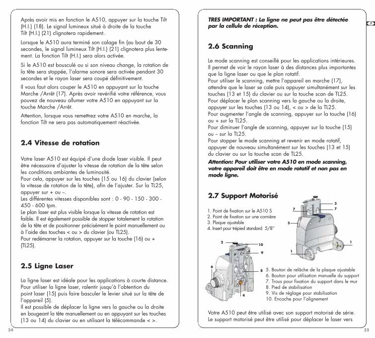
1.4 Vue du laser
1. Tête rotative 2. Protection de tête en aluminium résistant3. Sortie du rayon laser pour équerrage ou alignement vertical 4. Sortie du rayon laser horizontal 5. Clapet Mode ligne /Mode point 6. Index pour alignement et 90°7. Support motorisé8. Emplacement de la batterie 9. Connecteur Jack pour recharge de l’appareil10. Insert horizontal pour trépied standard (5-8’’)11. Insert vertical pour trépied standard (5-8’’)12. Capteurs pour télécommande
30
GB F E D I N FIN NL
Bien que chaque modèle A510 soit très simple d’utilisation,nous vous recommandons vivement de lire ce manuel avant d’u-tiliser le niveau laser.
1.1 Description
Le niveau laser A510 est un laser automatique visible qui peutêtre utilisé pour réaliser des nivellements, des alignements verticaux, des équerrages. Les applications possibles de celaser sont la pose de faux-plafonds, les planchers techniques,les cloisons et une grande variété d’applications extérieures.L’A510G a un faisceau vert qui est idéal pour un usage enintérieur quand une visibilité élevée est souhaitable. Il peut aussiêtre utilisé en extérieur avec le détecteur RCR500G.
Le A510 possède les fonctions suivantes :
• Calage automatique en mode vertical et horizontal. • Choix de rayons : point / ligne / scanning• Calibrage électronique • Equerrage permanent• Alignements vertical droite / gauche• Support mural motorisé de série / Support pour plan incliné• Peut être utilisé pour réaliser des pentes manuelles jusqu’à 10%
sur les axes X et Y.
1.2 Sécurité
Le A510 est un laser de Classe 3R et et répond aux normes inter-nationales de sécurité sur les lasers EN60825-1. Bien que la puis-sance du rayon n’excède pas 5mW dans la classe 3R, nous vousdemandons de respecter les points suivants : • Ne pas fixer directement le rayon laser• Ne pas faire passer le rayon à travers un instrument optique.
1. Généralités
CLASS 3R LASER PRODUCTWAVE LENGTH 630-680 nmMAX. OUTPUT POWER: 5mW
LASER LIGHT; AVOID DIRECT EYE EXPOSURECONFORMS TO IEC 60825-1; 2001
A510S
(Diamètre)Jusqu’à 60 m
300 m avec RCR500
± 0.0075% ± 7,5 mm à 100 mHorizontal et vertical
± 10% ; 5,7°Manuel sur les axes X et Y, mode semi-automatique avec X
en automatique et Y en manuel0, 90,150, 300, 450, 600 tpm
De 2 à 36°Class 3R ; <5mW
2 Piles alcaline type D ou batterie rechargeable
A510G
(Diamètre)Jusqu’à 100 m
300 m avec RCR500G
Diode rouge, 635nm Diode verte, 532nm
160 heures (20° C)40 heures / NiCD
15 heures-10° à 50° C-20° à 80° C
18 heures (20° C)20 heures / NiMH
8 heures-10° à 40° C *-20° à 60° C
Distance d’utilisationEn intérieur, en fonctionde la lumièreEn extérieur, avecdétecteur PrécisionNivellement automatiquePlage de nivellementPente manuelle de 10%
Vitesse de rotationAngles de scanningClasseDiode laserEnergieAutonomie - alcalineAutonomie - rechargeableTemps de chargeTempérature d’utilisationTempérature de stockagePlage de détection de latélécommandeEtancheitéTaille**
* Un échauffement peut être requis lors de basses températures. Voir la section “Entretien et recommandations”.
** Avec support mural et pack batteries rechargeables.
1.3 Specifications
30 m ; 180°
Résistant à la pluie et à la poussière (IP54)28 x 18 x 20.5 cm ; 2,3 kg
A510S-jun2009.qxp 15/07/09 17:41 Page 30

33
Vous pouvez choisir la vitesse la plus adaptée à votre applica-tion selon les conditions ambiantes de luminosité.
7. Pour éteindre le A510, appuyer sur la touche Marche/Arrêt (17).
• Verticale :
Pour une utilisation du A510 en mode vertical, nous vousrecommandons l’utilisation de son support motorisé, (pour plusde stabilité, déplier la rallonge du support). Il peut être égale-ment posé directement sur le sol ou fixé sur un trépied en util-isant l’insert pour trépied standard 5/8’’ du support mural.Une vue du laser et du clavier est disponible sur le dos de lacouverture et la fonction de chaque touche est décrite dans leparagraphe précédent. Après sa mise en fonction. Le rayon clignote jusqu’au calagede l’appareil. Lorsque l’appareil sera de niveau, la rotation dela tête démarrera.
2.2 Mode Automatique / Mode Manuel
Le A510 est par défaut en mode automatique lorsqu’il est misen marche. Lorsque l’appareil sera calé, la rotation de la têtesera activée. En activant le mode manuel (19), la rotation de la tête sera con-stante et ne sera pas stoppée si le niveau change ou si leniveau n’est pas bon. Le mode manuel est généralement utilisépour réaliser des plans inclinés comme des escaliers, des toits,des charpentes ou encore pour réaliser des pentes manuelles.
2.3 Fonction Tilt (H.I.)
Cette fonction n’est disponible que si elle est activée. Cette fonction stoppera la rotation de la tête et coupera lerayon laser si l’altitude du laser change ou si l’appareil estbousculé. L’arrêt de la rotation sera couplé à la mise en fonction d’une alarme sonore.
Attention : La fonction Tilt (H.I.) n’est disponiblequ’en mode automatique et semi-automatique.
32
GB F E D I N FIN NL
1.5 Vue du clavier
13. Déplacement à gauche : point, ligne, scan ou alignement vertical /Monter le point
14. Déplacement à droite : point, ligne, scan ou alignement vertical / Descendre le point
15. Réduire la vitesse de rotation - Diminuer angle de scanning / Sauver les données de calibrage
16. Augmenter la vitesse de rotation - Augmenter angle de scanning/ Changer l’axe de calibrage
17. Marche / Arrêt18. Activation de la fonction Tilt (H.I.) 19. Activation du mode manuel 20. Signal de batterie faible / Signal de calibrage de l’axe X /
Témoin de réception de la télécommande. 21. Signal Tilt (H.I.) en fonction / Signal de calibrage de l’axe Y 22. Signal d’activation du mode manuel / Signal de calibrage de
l’axe Z
Les fonctions en italique correspondent aux fonctions du mode calibrage.
2.1 Mise en station
• Horizontale :
1. Le A510 peut être posé directement sur le sol ou peut êtrefixé sur un trépied standard en utilisant son insert 5/8 ‘’. 2. Appuyer sur la touche Marche/Arrêt (17). L’appareil se mettra de niveau automatiquement. 3. Pour sélectionner le mode manuel, appuyer sur Man (19).4. Pour activer le mode Tilt, appuyer sur la touche H.I. duclavier (18). Cette fonction ne sera activée que 30 secondesaprès le démarrage de la rotation de la tête.5. Si vous souhaitez stopper la rotation et positionner manuelle-ment le point laser où vous souhaitez, appuyer sur latouche – (15) jusqu’à l’arrêt de la tête. 6. Pour augmenter ou diminuer la vitesse de rotation de la tête,appuyer sur la touche – ou + du clavier (15 ou 16), 6 vitessesde rotation différentes sont disponibles.
2. Comment utiliser le A510
A510S-jun2009.qxp 15/07/09 17:41 Page 32
35
GB F E D I N FIN NL
34
Après avoir mis en fonction le A510, appuyer sur la touche Tilt(H.I.) (18). Le signal lumineux situé à droite de la touche Tilt (H.I.) (21) clignotera rapidement.
Lorsque le A510 aura terminé son calage fin (au bout de 30secondes, le signal lumineux Tilt (H.I.) (21) clignotera plus lente-ment. La fonction Tilt (H.I.) sera alors activée.
Si le A510 est bousculé ou si son niveau change, la rotation dela tête sera stoppée, l’alarme sonore sera activée pendant 30secondes et le rayon laser sera coupé définitivement.
Il vous faut alors couper le A510 en appuyant sur la toucheMarche /Arrêt (17). Après avoir revérifié votre référence, vouspouvez de nouveau allumer votre A510 en appuyant sur latouche Marche /Arrêt.
Attention, lorsque vous remettrez votre A510 en marche, lafonction Tilt ne sera pas automatiquement réactivée.
2.4 Vitesse de rotation
Votre laser A510 est équipé d’une diode laser visible. Il peutêtre nécessaire d’ajuster la vitesse de rotation de la tête selonles conditions ambiantes de luminosité. Pour cela, appuyer sur les touches (15 ou 16) du clavier (selonla vitesse de rotation de la tête), afin de l’ajuster. Sur la TL25, appuyer sur + ou -.Les différentes vitesses disponibles sont : 0 - 90 - 150 - 300 -450 - 600 tpm. Le plan laser est plus visible lorsque la vitesse de rotation estfaible. Il est également possible de stopper totalement la rotationde la tête et de positionner précisément le point manuellement ouà l’aide des touches < ou > du clavier (ou TL25).Pour redémarrer la rotation, appuyer sur la touche (16) ou +(TL25).
2.5 Ligne Laser
La ligne laser est idéale pour les applications à courte distance.Pour utiliser la ligne laser, ralentir jusqu’à l’obtention du point laser (15) puis faire basculer le levier situé sur la tête del’appareil (5). Il est possible de déplacer la ligne vers la gauche ou la droiteen bougeant la tête manuellement ou en appuyant sur les touches(13 ou 14) du clavier ou en utilisant la télécommande < >.
TRES IMPORTANT : La ligne ne peut pas être détectéepar la cellule de réception.
2.6 Scanning
Le mode scanning est conseillé pour les applications intérieures. Il permet de voir le rayon laser à des distances plus importantesque la ligne laser ou que le plan rotatif. Pour utiliser le scanning, mettre l’appareil en marche (17),attendre que le laser se cale puis appuyer simultanément sur lestouches (13 et 15) du clavier ou sur la touche scan de TL25.Pour déplacer le plan scanning vers la gauche ou la droite, appuyer sur les touches (13 ou 14), < ou > de la TL25. Pour augmenter l’angle de scanning, appuyer sur la touche (16)ou + sur la TL25.Pour diminuer l’angle de scanning, appuyer sur la touche (15)ou - sur la TL25.Pour stopper le mode scanning et revenir en mode rotatif,appuyer de nouveau simultanément sur les touches (13 et 15)du clavier ou sur la touche scan de TL25. Attention: Pour utiliser votre A510 en mode scanning,votre appareil doit être en mode rotatif et non pas enmode ligne.
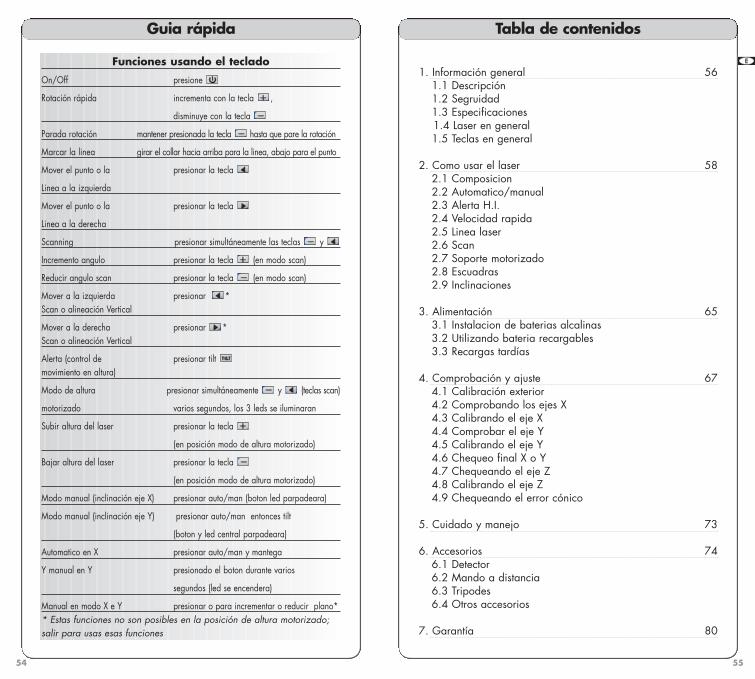
2.7 Support Motorisé
Votre A510 peut être utilisé avec son support motorisé de série. Le support motorisé peut être utilisé pour déplacer le laser vers
1. Point de fixation sur le A510 S 2. Point de fixation sur une cornière3. Plaque ajustable4. Insert pour trépied standard 5/8’’
1
110
2
6
9
8
4
377
5
5. Bouton de relâche de la plaque ajustable6. Bouton pour utilisation manuelle du support7. Trous pour fixation du support dans le mur 8. Pied de stabilisation9. Vis de réglage pour stabilisation10. Encoche pour l’alignement
A510S-jun2009.qxp 15/07/09 17:41 Page 34

37
GB F E D I N FIN NL
36
le haut ou le bas lorsque le laser est fixé sur une cornière etpeut être également utilisé pour positionner précisément le pointlaser sur le point de référence en mode vertical.
Il est important de noter que la plage de déplacementdu laser est de 5 cm vers le haut et 6 cm vers le bas.
Comment fixer le support sur le A510
Fixer le support mural motorisé sur le A510 en tournant lesdeux vis (1) situées sur les deux côtés du support mural. Ces deux vis doivent rester propres car elles permettent l’alimentation du support en électricité.Assurez-vous que le crochet de sécurité soit bien enclenché.
Utiliser le support mural sur une cornière
1. Déplier le pied rétractable du support mural. 2. Relâcher le clapet de fixation (2) situé sur le dessus de la plaqueajustable.3. Positionner la plaque sur la cornière et bloquer le clapet (2). La cornière ne doit pas excéder une épaisseur de 3 mm. 4. Pour déplacer le laser :
Manuellement : • Tourner le bouton situé sur le côté du support mural pour faire
monter ou descendre le laser (6).Avec une télécommande : • Une fois l’appareil basculé sur le côté appuyer pendant
plusieurs secondes sur la touche ‘scanning’ de la télécommande. 4 bips sonores signalent que vous étes en mode “support mural”.Attention : le mode “support mural” ne sera activé que si le supportest correctement connecté.
• Appuyer sur la touche + pour faire monter le laser • Appuyer sur la touche - pour faire descendre le laser.
Si le mode Tilt (H.I.) était activé avant d’actionner le mode supportmural, le mode Tilt (H.I.) sera automatiquement coupé durant l’ascension ou la descente du laser.Après 5 minutes de non utilisation du mode support mural(montée ou descente), le A510 reviendra automatiquement dans lemode initial (long bip de 4 secondes).
Utiliser le support mural sur le sol
1. Mettre le A510 fixé sur son support en mode vertical sur le sol. 2. Déployer le pied situé sur la plaque ajustable du support mural. 3. Ajuster la vis située sur ce pied afin de stabiliser le laser sur le sol.4. Appuyer sur la touche scanning de la télécommande plusieurs
secondes afin de mettre en fonction le mode « support mural ».4 bips sonores signalent que vous étes en mode « support mural » .5. Appuyer sur la touche (16) pour que l’appareil se déplacevers l’avant et sur la touche (15) pour que l’appareil se déplacevers l’arrière.6. Il est également possible de bouger manuellement le lasersur son support en utilisant le bouton situé sur le coté gauche du support mural.
Après quelques minutes de non utilisation du mode supportmural (montée ou descente), le A510 reviendra automatique-ment dans le mode initial (long bip de 4 secondes).
2.8 Equerrage
1. Mettre le A510 en mode vertical, le mettre en fonction-nement et ouvrir l’opercule de protection. 2. Arrêter la rotation de la tête en actionnant la touche -jusqu’à l’arrêt de la tête.3. Pour positionner le plan rotatif perpendiculaire à une lignede référence :
Sans le support mural motorisé :
• Faire coïncider les index situés sur la tête avec les indexsitués sur la coque de l’appareil. • Déplacer le laser de manière à ce que le rayon soit sur lepoint de référence sur le sol et ce, en conservant la correspondance faite à l’étape précédente.• Aligner le point fixe (3) sur le second point de référence en utilisant les touches (13 ou 14). Ce point sera parfaitement perpendiculaire, 90°, au plan rotatif. • Démarrer la rotation de la tête en maintenant enfoncée latouche + du clavier pendant 2 secondes.
Avec le support motorisé :
• Placer le laser sur le sol de telle manière à ce que l’indexsitué sur la tête soit sur votre point de référence. En utilisant latélécommande ou le bouton situé sur le coté du support mural,ajuster la position du laser de telle manière à ce que le pointsoit en correspondance avec votre point de référence.• Aligner le point laser fixe (3) sur le second point de référenceen utilisant les touches (13 ou 14). Ce point sera parfaitementperpendiculaire à 90°, au plan rotatif. Démarrer la rotation de la tête en maintenant enfoncé la touche + (16) pendant 2 secondes.
GB F E D I N FIN NL
A510S-jun2009.qxp 15/07/09 17:41 Page 36

39
La fonction Tilt (H.I.) n’est pas disponible lorsquevotre A510 est en mode manuel.
2.9.3 Plan incliné
Le laser peut aussi être incliné jusqu’à 90° sur le support pourréaliser une pente manuelle. Un trépied avec une plaque desupport rotative (embase) accélérera la mise en station.
1. Positionner le laser en mode vertical, de préférence sur untrépied. En cas de positionnnement au sol, pivoter vert le bas laplaque de support pour augmenter la stabilité.2. Une fois que le laser s’est calé automatiquement, passer enmode manuel ou semi-automatique. 3. Desserrer les boutons de chaque côté (1) pour séparer par-tiellement le support du laser.4. Mettre le laser en position inclinée le plus proche de laposition souhaitée et resserrer légèrement les boutons. 5. Ajuster en position finale et resserrer davantage.
3.1 Installer des piles alcalines
1. Pour utiliser des piles alcalines dans votre A510, utiliser untournevis ou une pièce afin de dévisser le boitier pile ou batteriesitué sur le dos de l’appareil. 2. Faire glisser le pack pour l’enlever. 3. Insérer deux piles alcalines (type D ou LR20) en respectant lapolarité (+ et -) comme indiqué dans le fond du pack pile. 4. Mettre le pack pile dans son compartiment et revisser en utilisant un tournevis ou une pièce.
3.2 Pour remplacer les piles alcalines
Lorsque les batteries du A510 sont faibles, la tête cessera detourner et le signal lumineux placé à proximité de la toucheMarche/Arrêt clignotera (20).
Remplacer les deux piles alcalines en même temps en respectant lapolarité indiquée dans le fond du pack pile.
GB F E D I N FIN NL
38
Il est très important de vérifier que votre laser n’a pasbougé et que vos mesures sont toujours précises.
2.9 Pente Manuelle
Le A510 peut être utilisé pour réaliser des pentes manuellesjusqu’à 10% sur les axes X et Y.
Deux modes sont disponibles :
• Mode manuel : Les axes X et Y sont totalement manuels.• Mode semi-automatique : X est automatique et Y est manuel.
Le mode manuel sera principalement utilisé pour réaliser desplans inclinés tels que des escaliers, des toits, des charpentes,…Le mode manuel peut également être utilisé avec le supportmural motorisé ou tout autre support.
2.9.1 Démarrer avec le mode manuel
1. Mettre votre A510 en marche.2. Appuyer sur la touche (19) pour activer le mode manuel. Le symbole lumineux (22) clignotera pour vous informer quevotre laser est en mode manuel. 3. Appuyer sur la touche (13 ou 14) pour faire une pente sur l’axe X. 4. Pour faire une pente sur l’axe Y, appuyer sur la touche Tilt (H.I.) (18). Les deux leds (21) et (22) clignoteront rapidement pour vous informer qu’une pente peut être sélectionnée sur l’axe Y. 5. Appuyer sur les touches (13 ou 14) pour faire une pente surl’axe Y.
2.9.2 Démarrer le mode semi-automatique
1. Mettre votre laser en marche.2. Appuyer sur la touche (19) pendant plusieurs secondes. Le signal lumineux (22) restera allumé. 3. Utiliser les touches (13 ou 14) pour faire une pente surl’axe Y.
Il est possible d’utiliser la fonction Tilt (H.I.) qui ne sera activeque sur l’axe X. Appuyer de nouveau sur la touche (19) pourrevenir en mode manuel. Appuyer une seconde fois sur latouche (19) pour revenir en mode automatique.
IMPORTANT : En mode manuel, la tête tourneramême si votre A510 n’est pas de niveau.
3. Alimentation
A510S-jun2009.qxp 15/07/09 17:41 Page 38

4140
GB F E D I N FIN NL
Ce chapitre est très important. Vous trouverez ci-après quelquesinformations simples vous permettant de contrôler le calibrage devotre A510. Nous vous rappelons que le A510 est un instrumentde précision et qu’il est important qu’il soit maintenu calibré et enbon état. La précision de votre travail est totalement sous votreresponsabilité. Vous devez contrôler régulièrement la précision devotre laser et ce particulièrement avant tout chantier important. Vous trouverez ci-après quelques instructions très simples vous per-mettant de contrôler votre appareil et de le calibrer si nécessaire. Il vous est également possible de le renvoyer dans un service après-vente agréé.
4.1 Contrôle et calibrage horizontal (Axes X et Y)
4.1.1 Contrôle
1. Placez le laser sur une surface plane à environ 30 mètresd’un mur. Positionnez l’appareil de telle manière à ce que l’axeX’ soit face au mur. 2. Mettre l’appareil en marche. Lorsque l’appareil est calé,arrêtez la rotation en appuyant sur la touche (15). Si la lumière est trop présente pour voir le laser, utilisez une cellule de détec-tion, ou passez en mode scan.3. Viser le mur à 30 mètres et marquer la position du point X’ sur le mur.4. Faire pivoter le laser de 180°. Lorsque le laser s’est recalé,marquer la position du second point X sur le mur à 30 mètres, àproximité de la première marque X’.
4. Vérifier et calibrer votre A510
Les touches du clavier de la cellule de détection en mode calibrage
Utilisez les flèches pour fairemonter ou descendre le rayonlaser afin d’ajuster le calibrage
Si vous utilisez la télécommande TL25, les touches portent les mêmes symboles correspondant aux mêmes fonctions
Passez de l’axe X à l’axe Y
Sauvez le calibrage
Démarrez le calibrage (en mode calibrage)
3.3 Utilisation de batteries rechargeables
Si votre laser a une batterie rechargeable, vous devez le rechargeravant la première utilisation. N’utiliser que le chargeur inclus avecvotre laser. Les chargeurs des deux modèles, A510S et A510G,ne sont pas interchangeables.
1. Insérer la fiche du chargeur dans la prise Jack du pack batterie. 2. Pour l’A510S : Brancher le chargeur dans une prise 110V ou 120V AC. Le temps de charge est de 15 heures.
Pour l’A510G, qui a un chargeur universel : sélectionnerl’adaptateur approprié à votre pays, ajustez le sur le chargeurpuis brancher celui-ci dans une prise 110V ou 220V AC. Letemps de charge est de 8 heures.
3.4 Recharger les batteries
Le A510 peut être chargé en travaillant si l’électricité estdisponible sur votre chantier. Vous n’avez qu’à brancher votreappareil dans une prise et vous pouvez continuer à travailler. Il vous est également possible de retirer le pack de batterierechargeable et de le remplacer par le pack piles alcalines.
L’A510S a une batterie rechargeable NiCd. Pour augmenter ladurée de vie des batteries, nous vous recommandons derecharger les batteries lorsque celles-ci sont totalement vides etde ne pas les recharger durant plus de 20 heures.
L’A510G a une batterie rechargeable NiMH, avec un contrôleélectronique pour éviter la surcharge.
Les batteries et le chargeur peuvent être endommagés s’ils sont aucontact de l’eau.
Nous vous recommandons de conserver et de stocker les batterieset le chargeur dans des endroits secs et couverts.
A510S-jun2009.qxp 15/07/09 17:41 Page 40

43
GB F E D I N FIN NL
42
6. Si l’axe Y ne doit pas être calibré, vous pouvez sauvegarderles données en appuyant sur la touche - ou • (15) du clavier. Si vous pensez avoir fait une erreur lors de la calibration, vouspouvez sortir du mode calibration et revenir à la calibrationprécédente en appuyant simplement sur la touche Marche /Arrêt.
Si l’axe Y doit être calibré, vous pouvez changer l’axe de calibration en appuyant sur la touche + ou >>I (16). Le signallumineux placé à proximité de la touche Tilt (H.I.) (21) clignotera pour vous informer que votre laser est prêt à être calibré sur l’axe Y.
Calibrage de l’axe Y
1. Assurez-vous que le signal lumineux situé à proximité de latouche Tilt (H.I.) clignote. Sinon :
• Tout en maintenant appuyé la touche Man (19), allumerl’appareil (17).
• Après quelques secondes, relâchez la touche Marche/Arrêt.• Lorsque la LED (20) est allumé, relâchez la touche Man.
Le signal lumineux (20) clignotera rapidement puis lentement pourvous indiquer que vous êtes en mode calibrage.
• Appuyez sur la touche + ou >>I (16) pour changer l’axe decalibrage. Le signal lumineux (21) clignotera alors pour vousinformer que vous pouvez calibrer l’axe Y.2. Faites pivoter votre laser de telle manière à ce que l’axe Ysoit face au mur (où vous avez marqué le point de calibrage Y). 3. Attendez que l’A510 soit calé. Si vous préférez la ligne rota-tive appuyez sur la touche scan.4. Appuyez sur la touche < (13) pour monter le point ou sur latouche > (14) pour baisser le point jusqu’à arriver au point de calibrage Y. 5. Pour sauvegarder les données, appuyez sur la touche - ou • (15).6. Si vous pensez avoir fait une erreur lors du calibrage del’axe Y, vous pouvez sortir du mode calibrage et revenir au calibrage précédent en appuyant sur la touche Marche /Arrêt.
4.2 Contrôle et calibrage vertical (axe Z)
4.2.1 Contrôle vertical
1. Placer le A510 en mode vertical sur une surface plate àenviron 6 mètres d’un fil à plomb courant le long d’un mur.2. Mettre le laser en marche et attendre que le laser se cale.
5. Les deux marques X et X’ doivent être très proches. A 30mètres, la différence de hauteur entre les deux points ne doit pasexcéder 5 mm (précision de ± 0,0075%, soit +/- 7,5 mm à 100 m.6. Si la distance est supérieure à 5 mm, l’axe X de votre laserdoit être calibré.7. Faire une marque au centre des marques X et X’. Cette mar-que sera le point de calibration de l’axe X.8. Pour contrôler l’axe Y, faites pivoter le laser de 90° de tellemanière à ce que l’axe Y’ soit face au mur. Marquer le point Y’. 9. Faites pivoter le laser de 180° et marquer la position Y dulaser sur le mur. 10. Les deux marques Y et Y’ doivent être très proches. A 30mètres, la distance séparant les deux marques ne doit pasexcéder 5 mm. Si la distance est supérieure à 5 mm, l’axe Y devotre laser doit être calibré. 11. Faites une marque au centre des points Y et Y’. Ce pointsera le point de calibration de l’axe Y.
4.1.2 Calibrage des axes X et Y
Le laser doit être calibré de manière à amener le point laser aucentre des marques précédemment définies. Le calibrage du A510 est facilement réalisé en utilisant les touchesdu clavier ou en utilisant la télécommande.
Calibrage de l’axe X
1. Si votre A510 est en fonction, éteignez-le. 2. Faites pivoter votre laser de manière à ce que l’axe X -X’soit face au mur sur lequel vous avez marqué le point de calibrage de l’axe X. 3. Tout en maintenant appuyé la touche Man (19), allumer l’appareil. 4. Après quelques secondes, relâchez la touche Marche /Arrêt.Lorsque la LED (20) est allumé, relâcher la touche Man. Le signelumineux (20) clignotera alors rapidement puis lentement pour vousinformer que votre A510 est prêt à être calibré sur l’axe X. Si vous préferez la ligne rotative appuyez sur la touche scan.5. Appuyer sur la touche < (13) pour monter le point ou sur latouche >(14) pour descendre le point jusqu’à atteindre le point decalibration X marqué sur le mur dans les étapes précédentes.
Important : Une pression sur la touche du clavier est équiva-lente à un réglage de 1mm à 100 mètres.
A510S-jun2009.qxp 15/07/09 17:41 Page 42

45
GB F E D I N FIN NL
44
ATTENTION Le contrôle ou le calibrage de votre appareil suivantdes procédures autres que celles décrites dans cemanuel d’utilisation pourraient vous exposer à desradiations dangereuses.
Le A510 est un instrument de précision qui doit être manipuléavec précaution et soin. Eviter le plus possible les chocs et lesvibrations. Pour éviter les chocs et les vibrations, toujours trans-porter le A510 et ses accessoires dans sa mallette.
Bien que votre A510 soit résistant à la pluie et à la poussière,vous devez le conserver, ainsi que ses accessoires, secs et pro-pres. Nous vous recommandons de le nettoyer ainsi que sesaccessoires après chaque utilisation.
Conserver le A510 dans un endroit sec pour augmenter la duréede vie des batteries.
Ne pas ranger le A510 dans sa mallette s’il est mouillé, ou s’il y ade l’eau dans la mallette pour éviter les effets de condensation oude buée.
Vérifiez régulièrement votre appareil pour maintenir la précision devotre A510.
Conserver la lentille de sortie du laser propre. La nettoyer avec unchiffon doux et du nettoyant pour vitre si besoin.
7. Marquer la position du point sur le mur (a’) en utilisant sinécessaire un détecteur. 8. Comparer les deux mesures : si la différence entre aa’-bb’ estsupérieure à 5 mm, contacter votre service après-vente local.
5. Entretien et Recommandations
3. Passer en mode scanning.4. Déplacer le scanning manuellement le long du fil à plomb.Si le plan n’est pas parfaitement parallèle au fil à plomb, l’axeZ doit être calibré.
4.2.2 Calibrage de l’axe Z
1. Eteindre l’appareil. 2. Mettre le A510 en mode vertical. Tout en maintenantappuyé la touche Man (19), allumer l’appareil (17).3. Après le clignotement des 3 LED, relâchez la touche Man (19).4. Le signal lumineux situé à proximité de l’indication Z (22)clignotera pour vous informer que votre A510 est prêt à êtrecalibré sur l’axe Z.5. Déplacer le plan laser en utilisant les touches (< 13 ou >14) demanière à ce que le plan soit parfaitement parallèle au fil à plomb. 6. Déplacer le point laser le long du fil à plomb manuellementou à de manière à procéder au contrôle final.7. Appuyer sur la touche - ou • (15) afin de sauvegarder lesdonnées ou appuyer sur la touche Marche/Arrêt si vous pensezavoir fait une erreur.
4.3 Contrôle d’erreur conique
1. Positionner votre A510 à 1 mètre d’un mur (a) ou d’une mireet à 30 mètres d’un autre mur (b) ou d’une autre mire.2. Mettre le laser en marche.3. Lorsque le laser est calé, stopper la rotation de la tête enappuyant sur la touche (15) jusqu’à l’arrêt de la tête.4. Marquer alors la position du centre du rayon sur le murproche (a) manuellement ou en utilisant un détecteur si les con-ditions ambiantes de luminosité vous empêche de voir parfaite-ment le point. 5. Marquer également la position du centre du rayon sur le murle plus éloigné (b), en utilisant un détecteur si nécessaire. 6. Installer le A510 à 1 mètre du mur (b) Lorsque le A510 estcalé, pointer le point laser proche de la marque précédente (b)et faire une nouvelle marque (b’).
A510S-jun2009.qxp 15/07/09 17:41 Page 44

47
GB F E D I N FIN NL
46
Conseils de manipulation pour l’A510S :Ne pas conserver votre laser à des températures en dessousde -20°C ou au dessus de 80°C.Nous vous recommandons de recharger régulièrement lesbatteries NiCd de l’A510S. Rechargez-les uniquement quandelles sont vides ou proche de l’être. La recharge des batteriesde l’A510S quand elles sont toujours utilisables réduira leurcapacité.
Conseils de manipulation pour l’A510G :Ne pas conserver votre laser à des températures en dessousde -20°C ou au dessus de 60°C.
Lors de basses températures, un temps de chauffe peut êtrerequis. Si vous utilisez le laser quand les températures sontentre -10° et 0°C, le rayon du laser sera visible sous 10 à12 minutes and attendra sa pleine puissance sous 20 à 25minutes.
GB F E D I N FIN NL
6. Accessoires
6.1 Cellule de détection/télécommande
Elle convient pour les mires graduées ou d'autres applicationsmanuelles. Avec l’A510S utiliser le détecteur RCR500 ; avecl’A510G, utilisez le RCR500G. Grâce à son support magné-tique, elle peut être aussi utilisée pour des alignements de mursen extérieur ou pour ajuster en plafond les grilles acoustiques.
EcranLCD (face)
Repèred’alignement
Fênetre de détection
Aimant
Fenêtre pour le signal infrarougede la télécommande
Niveau à bulle
Ecran LCD (dos)
Niveau àbulle pour
la mire
Compartiment pour la
batterie 9V(merci de respecter lespolarités à l’intérieur)
Bouton de fixationde la bride à lacellule
Bouton de fixation de labride à la mire
GB F E D I N FIN NL
Choix duniveau sonore
Déplace le point
vers la gauche
Déplace le point
vers la droite
Dirige le scan vers la gauche
Dirige le scan vers la droite
et sont réservés au cali-brage ou au réglage manuel
Choix du niveaudela précision
Marche / Arrêt
• Partie haute du clavier
Mode détectionMode télécommande Mode scanning
A510S-jun2009.qxp 15/07/09 17:41 Page 46

49
GB F E D I N FIN NL
48
GB F E D I N FIN NL
Batterie faible
Clignote : volume normal
Permanent : volume fort
Pas de signal : muet
Standard Fin
Bas
Intermediairebas
Sur lelaser
Intermediaire haut
Haut
ETAT
DE LA BATTERIE
SON
PRÉCISION
(Par défaut)
• Ecran LCD
• Utiliser la cellule
1. Presser le bouton On/Off pour mettre en marche la cellule.2. Presser le bouton central pour choisir le mode de précision.3. Presser le bouton du haut pour choisir le niveau sonore souhaité.4. Faire pivoter la fenêtre de détection vers le rayon laser etdéplacer la cellule vers le haut ou le bas suivant l’indicationfournie sur l’écran LCD.Il existe 5 niveaux d’information. Une flèche vers le bas indique que la cellule doit être déplacéevers le bas pour atteindre le niveau de référence du laser. Une flèche vers le haut sur l’écran, indique qu’il faut monter lacellule au contraire. Lorsqu’une ligne horizontale apparaît surl’écran, cela signifie que la cellule est au niveau du rayon laser.5. Presser la touche On/Off pour éteindre la cellule. Elles’éteindra automatiquement après 10 minutes de non utilisation(un signal sonore vous l’indiquera).
GB F E D I N FIN NL
• Partie inferieure du clavier
Augmente la vitessede rotation
Diminue la vitessede rotation
Augmente l'anglede scanning
Diminue l'angle descanning
La partie calibrage du manuel décrit les fonctionsdes symboles inscrits en petit sur les touches.
Marche/Arrêt du mode scanning
Mode télécommande
Mode scanning
DÉPANNAGE
• Avant d’utiliser une cellule de détection, il est important denoter que votre A510S doit être en mode point et non pas enmode ligne. Les cellules de détection ne peuvent pas détecter lelaser en mode ligne.• Si vous ne captez pas le rayon avec le détecteur, vérifiez votrealignement avec le laser. Un des supports de la protection de têtedu laser peut bloquer le rayon, déplacez vous vers la gauche oula droite pour capter le rayon.• La protection de tête en métal peut être ôtée du laser enpivotant les deux verrous de sécurité. Cela n’affectera pas lesperformances ou la résistance à l’eau ou la poussière du laser.• S’il fait froid et qu’il n’y a pas de signal venant de l’A510G,accordez lui un temps de chauffe (voir la section “Entretien etrecommandations”).
A510S-jun2009.qxp 15/07/09 17:41 Page 48

51
GB F E D I N FIN NL
50
GB F E D I N FIN NL
Vue de la télécommande
6.3 Trépieds
Le A510 peut être installé sur n’importe quel trépied possédantun insert standard 5/8’’.
6.4 Autres accessoires
• Les lunettes laser sont utilisées pour améliorer la visibilité durayon laser dans des conditions de forte luminosité. • La cible magnétique sera utilisée dans des applicationsintérieures. Elle permettra d’améliorer la visibilité du plan laser. Elle se fixe sur toute partie métallique.
Fenêtre infrarouge
Baterie AA
2
3
5
4
1GB F E D I N FIN NL
Mode laser1.2. Diminue la vitesse derotation3. Augmente la vitessede rotation4. Déplace le “pointpar point” à gauche5. Déplace le “pointpar point” à droite
Scanning1. On/Off du mode scan2. Réduction taille duscanning3. Augmentation tailledu scanning4. Déplace le scan àgauche5. Déplace le scan àdroite
Mode support mural1. Presser 3 sec. pouractiver le mode2. Déplacer le laservers le haut3. Déplacer le laservers le bas
• Mode télécommande
Le mode détection doit être arrêté pour utiliser le mode télécommande.
Ce mode permet d'arrêter ou de démarrer la rotation, l'augmenter ou ladiminuer, et déplacer le laser ou le point. Il permet aussi de contrôler lescanning et le calibrage électronique.
• Caractéristiques techniques
Distance maximale d’utilisation* 150 mPrécision* Fin ± 1 mm
Standard ± 2.5 mmAutonomie Batterie 50 heures (9 V Alcaline)Environnement Etanche ( IP 66 )Dimensions 15 x 8 x 3,5 cm /280 g**
*Dépend du laser utilisé. La précision varie en fonction du diamètre du rayon et de la distance jusqu’au laser.**Avec batteries
6.2 Télécommande
La télécommande pourra être utilisée pour : • Démarrer, stopper, ajuster la vitesse• Augmenter ou diminuer l’angle de scanning • Déplacer le plan laser à gauche ou à droite • Entrer et sortir des modes scanning, support mural, …• Calibrer le laser • Réaliser des alignements verticaux gauche ou droite • Développer tout ce qui se rapporte au support motorisé.
Pour changer la pile de la télécommande, ouvrir le logement pilesitué sur le dos de la télécommande et changer la pile en respec-tant la polarité indiqué dans le fond du logement de la pile.
A510S-jun2009.qxp 15/07/09 17:41 Page 50

A510S / A510GManual de operación
52
7. Garantie
Agatec accorde une garantie de deux ans sur le A510 (1 anpour l'Amérique du Nord, la garantie est étendue à 2 ans si leproduit est enregistré sur internet ou par courrier dans les 45jours suivant l'achat).De plus amples informations à ce sujet disponibles sur le siteInternet: www.agatec.com
A510S-jun2009.qxp 15/07/09 17:41 Page 52
55
GB F E D I N FIN NL
54
1. Información general 561.1 Descripción1.2 Segruidad1.3 Especificaciones1.4 Laser en general 1.5 Teclas en general
2. Como usar el laser 582.1 Composicion 2.2 Automatico/manual 2.3 Alerta H.I. 2.4 Velocidad rapida2.5 Linea laser2.6 Scan2.7 Soporte motorizado2.8 Escuadras2.9 Inclinaciones
3. Alimentación 653.1 Instalacion de baterias alcalinas3.2 Utilizando bateria recargables 3.3 Recargas tardías
4. Comprobación y ajuste 674.1 Calibración exterior 4.2 Comprobando los ejes X 4.3 Calibrando el eje X 4.4 Comprobar el eje Y 4.5 Calibrando el eje Y 4.6 Chequeo final X o Y 4.7 Chequeando el eje Z 4.8 Calibrando el eje Z 4.9 Chequeando el error cónico
5. Cuidado y manejo 73
6. Accesorios 746.1 Detector 6.2 Mando a distancia6.3 Tripodes6.4 Otros accesorios
7. Garantía 80
Tabla de contenidos
Funciones usando el teclado
On/Off presione
Rotación rápida incrementa con la tecla ,
disminuye con la tecla
Parada rotación mantener presionada la tecla hasta que pare la rotación
Marcar la linea girar el collar hacia arriba para la linea, abajo para el punto
Mover el punto o la presionar la tecla
Linea a la izquierda
Mover el punto o la presionar la tecla
Linea a la derecha
Scanning presionar simultáneamente las teclas y
Incremento angulo presionar la tecla (en modo scan)
Reducir angulo scan presionar la tecla (en modo scan)
Mover a la izquierda presionar *Scan o alineación Vertical
Mover a la derecha presionar * Scan o alineación Vertical
Alerta (control de presionar tilt movimiento en altura)
Modo de altura presionar simultáneamente y (teclas scan)
motorizado varios segundos, los 3 leds se iluminaran
Subir altura del laser presionar la tecla
(en posición modo de altura motorizado)
Bajar altura del laser presionar la tecla
(en posición modo de altura motorizado)
Modo manual (inclinación eje X) presionar auto/man (boton led parpadeara)
Modo manual (inclinación eje Y) presionar auto/man entonces tilt
(boton y led central parpadeara)
Automatico en X presionar auto/man y mantega
Y manual en Y presionado el boton durante varios
segundos (led se encendera)
Manual en modo X e Y presionar o para incrementar o reducir plano** Estas funciones no son posibles en la posición de altura motorizado;salir para usas esas funciones
Guia rápida
A510S-jun2009.qxp 15/07/09 17:41 Page 54

57
GB F E D I N FIN NL
56
1.4 Composición del láser
Ver en la tapa las fotos que corresponden a estas leyendas.Vea por separado las funciones para soporte techos, control remoto y detectores.
1. Cabezal de rotación2. Cabezal de aluminio
protegida en todos sus ejes3. Plomada o escuadra con
apertura rayo láser4. Apertura rayo láser5. Interruptor de cambio
entre punto o línea láser6. Señales para alineación y 90°
7. Soporte motorizado para techos o suelos
8. Baterías9. Enchufe para cargador de batería10. 5/8” montaje trípode
modo horizontal11. 5/8” montaje trípode
modo vertical12. Sensores para la señal del
control remoto
1.3 Especificaciones
1.1 Descripción
El A510 es un láser visible automático que puede ser usadopara nivelación, alineación vertical, plomadas y escuadras.Incluye aplicaciones de falsos techos, perfiles y una variedadde trabajos de alineación.El A510G tiene un rayo láser verde que es ideal para utilizaren interiores dónde se necesita un rayo de alta visibilidad.También puede usarse en exteriors con el detector RCR500G.
El A510 contiene estas funciones avanzadas:
• Autonivelante en vertical y horizontal• Soporte motorizado para la instalación rápida de
techos y perfiles• Nivelación manual en ejes x e y para una inclinación del ±10%• Inclinación semi automática (inclinación automatica en el
Eje de las X y manual en las Y)• Elección de rayos, incluyendo scan y línea láser• Escuadra ajustable a la derecha o izquierda• Fácil calibración electrónica
1.2 Cuidados
El A510 contiene un láser de clase 3R, manufacturado siguiendolas normas IEC 60825-1, 2001. La potencia del rayo láser es inferior a 5 mw en la clase 3R, las siguientes precauciones sonrecomendadas:
• No mirar directamente al rayo• No dirigir el laser al nivel de los ojos
1. Información general
CLASS 3R LASER PRODUCTWAVE LENGTH 630-680 nmMAX. OUTPUT POWER: 5mW
LASER LIGHT; AVOID DIRECT EYE EXPOSURECONFORMS TO IEC 60825-1; 2001
A510S
(Diámetro)Hasta 60 m (200’)
300 m (1,000’) con RCR500± 7,5 mm a 100 m (± 3/32” a 100’) ± 0.0075%
Horizontal y vertical± 10% ; 5,7°
Manual en ejes X e Y; Además, modo semi-automático con X en modo automático, Y en modo manual
0, 90,150, 300, 450, 600 rpmVariable de 2 a 36°Claser 3R; <5mW
2 baterías alcalinas 2 D (LR20) o baterías recargables
A510G
(Diámetro)Hasta 100 m (300’)
300 m (1,000’) con RCR500G
Diodo rojo, 635nm Diodo verde, 532nm
160 h (20° C/68° F)40 h / NiCD
15 horas-10° a 50° C (14° a122° F)
-20° a 80° C (-4° a176° F)
18 h (20° C/68° F)20 h / NiMH
8 horas-10° a 40° C (14° a 104° F)*
-20° a 60° C (-4° a 140° F)
Uso recomendadoInterior, depende de lailuminaciónExterior, con detectorPrecisión de niveladoAutonivelaciónRango autonivelación± 10% Grado manual
Velocidad de rotaciónÁngulo de scanClase de láserDiodo láser visibleAlimentaciónAutonomía-alcalinasAutonomía-recargablesTiempo de cargaTemperatura de funcionamientoTemperatura dealmacenamientoControl remotoProtección ambientalTamaño**
* En temperaturas bajas, puede necesitarse un período de calen-tamiento. Ver sección “Cuidado y manejo”.** Con el soporte y las baterías recargables.
30 m (100’) / 180°IP54; humedad (lluvia y polvo)
28 x 18 x 20.5 cm (11” x 7” x 8”); 2,3 kg (5.2 libras)
A510S-jun2009.qxp 15/07/09 17:41 Page 56
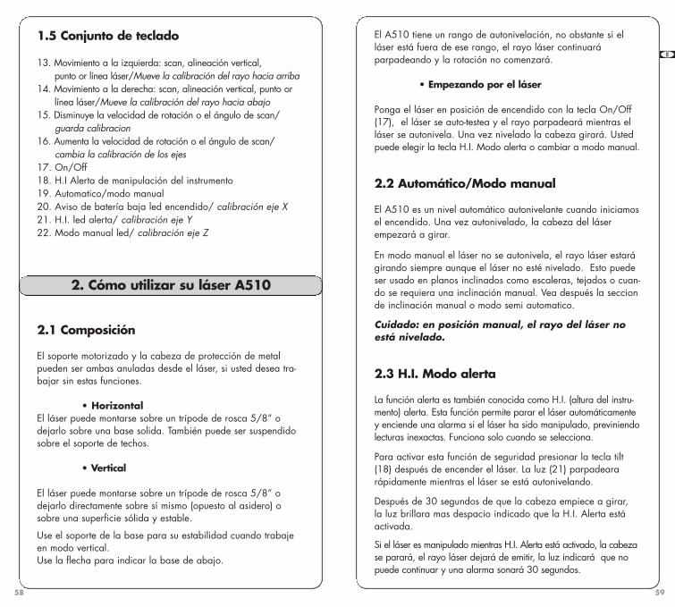
59
GB F E D I N FIN NL
58
El A510 tiene un rango de autonivelación, no obstante si elláser está fuera de ese rango, el rayo láser continuaráparpadeando y la rotación no comenzará.
• Empezando por el láser
Ponga el láser en posición de encendido con la tecla On/Off(17), el láser se auto-testea y el rayo parpadeará mientras elláser se autonivela. Una vez nivelado la cabeza girará. Ustedpuede elegir la tecla H.I. Modo alerta o cambiar a modo manual.
2.2 Automático/Modo manual
El A510 es un nivel automático autonivelante cuando iniciamosel encendido. Una vez autonivelado, la cabeza del láserempezará a girar.
En modo manual el láser no se autonivela, el rayo láser estarágirando siempre aunque el láser no esté nivelado. Esto puedeser usado en planos inclinados como escaleras, tejados o cuan-do se requiera una inclinación manual. Vea después la seccionde inclinación manual o modo semi automatico.
Cuidado: en posición manual, el rayo del láser noestá nivelado.
2.3 H.I. Modo alerta
La función alerta es también conocida como H.I. (altura del instru-mento) alerta. Esta función permite parar el láser automáticamentey enciende una alarma si el láser ha sido manipulado, previniendolecturas inexactas. Funciona solo cuando se selecciona.
Para activar esta función de seguridad presionar la tecla tilt(18) después de encender el láser. La luz (21) parpadeara rápidamente mientras el láser se está autonivelando.
Después de 30 segundos de que la cabeza empiece a girar, la luz brillara mas despacio indicado que la H.I. Alerta estáactivada.
Si el láser es manipulado mientras H.I. Alerta está activado, la cabezase parará, el rayo láser dejará de emitir, la luz indicará que nopuede continuar y una alarma sonará 30 segundos.
1.5 Conjunto de teclado
13. Movimiento a la izquierda: scan, alineación vertical, punto or línea láser/Mueve la calibración del rayo hacia arriba
14. Movimiento a la derecha: scan, alineación vertical, punto or línea láser/Mueve la calibración del rayo hacia abajo
15. Disminuye la velocidad de rotación o el ángulo de scan/ guarda calibracion
16. Aumenta la velocidad de rotación o el ángulo de scan/cambia la calibración de los ejes
17. On/Off18. H.I Alerta de manipulación del instrumento19. Automatico/modo manual 20. Aviso de batería baja led encendido/ calibración eje X21. H.I. led alerta/ calibración eje Y22. Modo manual led/ calibración eje Z
2.1 Composición
El soporte motorizado y la cabeza de protección de metalpueden ser ambas anuladas desde el láser, si usted desea tra-bajar sin estas funciones.
• HorizontalEl láser puede montarse sobre un trípode de rosca 5/8” odejarlo sobre una base solida. También puede ser suspendidosobre el soporte de techos.
• Vertical
El láser puede montarse sobre un trípode de rosca 5/8” odejarlo directamente sobre sí mismo (opuesto al asidero) osobre una superficie sólida y estable.
Use el soporte de la base para su estabilidad cuando trabajeen modo vertical.Use la flecha para indicar la base de abajo.
2. Cómo utilizar su láser A510
A510S-jun2009.qxp 15/07/09 17:41 Page 58

61
GB F E D I N FIN NL
60
Si el láser esta en línea láser, vuelva a la posición de punto antesde empezar con el modo scan.
1. Para scan presionar simultáneamente las teclas – y < sobre ellaser o presionar el símbolo de scan sobre el control remoto odel detector.2. El rayo parpadeará mientras el láser se está autonivelando.3. Para reducir la longitud de scan presione la tecla – , para incre-mentar la longitud scan presione la tecla + . Las teclas del controlremoto o detector pueden ser usadas tambien para la funciones descan.4. Para mover el scan hacia la izquierda presione la tecla <. Para mover el scan hacia la derecha presione la tecla >.5. Para parar el scan presione de nuevo simultáneamente las teclas – y <.
2.7 Soporte motorizado
2.7.1 Soporte motorizado
El soporte motorizado puede ser utilizado para desplazar el láserarriba o abajo sobre un soporte de techos. Ello puede ser utilizadopara trabajos en paredes y perfiles , al voltear el láser para alineación vertical.
1. Dispositivo de abrazaderas para láser y soporte
2. Abrazadera para soporte techos
3. Base ajustable4. Rosca 5/8” para montar
sobre trípode (modo vertical)
5. Control de ajuiste de la base6. Mover el laser manualmente
sobre el soporte7. Cavidades para colocar el
soporte de techos8. Soporte ajustable para techos
o estabilidad en suelos9. Tornillos de ajuste 10. Muesca para alineación
1
1
102
6
9
8
4
377
5
Apagar el láser y volver a empezar de nuevo. Chequee si laelevación del rayo ha sido cambiada de la posición original.
El láser no permanece en H.I. Modo alerta, presionar Tilt (18)para volver al modo H.I. Alerta
Esta función es solo posible en modo automático o semiau-tomático, y no en el modo de soporte.
2.4 Velocidad
La cabeza tiene 5 velocidades: 90, 150, 300, 450 y 600 rpm.300 rpm es por defecto la que el láser dispone . El rayo láseres mas visible cuando la velocidad de rotación es mas lenta.
Para incrementar la velocidad de rotación, presione la tecla +del laser. Presiona la tecla – para reducir la velocidad.Mantega la tecla – para la rotación.
Cuando el láser es parado, el punto puede ser movido a laderecha o la izquierda usando las teclas > o < . Usted puede también mover la cabeza manualmente y dirigir el punto láser.
2.5 Usando la línea láser
Ideal para aplicaciones a cortas distancias, la funcion línealáser consigue una precisa y estable línea láser para trabajardirectamente en sus planos de referencia.
Para usar la línea láser, pare la rotación y gire el collar local-izado en la cabeza de rotación. Este collar tiene un interruptorentre el punto y la línea.
Usted puede estacionar la línea a la izquierda presionando latecla < y a la derecha presionando la tecla >. Usted puede también mover la cabeza manualmente o usando el controlremoto.
Si el láser está en posición de laser línea el detector nopuede trabajar. Vuelva a la posición de punto para queel detector pueda detectar el rayo.
2.6 Scaneando
Para aplicaciones en interior, en el modo scan puede ver el rayofácilmente a distancia.
A510S-jun2009.qxp 15/07/09 17:41 Page 60

6362
GB F E D I N FIN NL
4. Cierre la abrazadera de nuevo al soporte de techos. El soporteno excederá 3 mm de grosor.5. Si el pie sobre la base del soporte no está en contacto con lapared, use el tornillo (9) para ajustar.
Para mover el láser arriba o abajo con el control remoto:
1. Encienda el láser y espere a que se autonivele. La cabezadeberá estar en rotación después usted puede entrar en el modosoporte.2. Presione la tecla scan y manténgala presionada varios segun-dos. Esto pondrá el láser en modo soporte. Los tres led (luces)parpadearan.3. Presione la tecla + para mover el láser arriba, presione latecla – para mover el láser abajo. Presionando la tecla elmovimiento sera rápido, con presiones cortas el movimiento delláser será mas preciso.
2.7.3 Usando el soporte motorizado y láser en el suelo
1. Compruebe que el láser y el soporte están conectados correctamente. Los tornillos (1) deben estar apretados parahacer contacto con el motor.2. Liberar hacia abajo la base del soporte (8) y ponga el laseren modo vertical en el suelo.3. Si la base no está nivelada, use los tornillos (9) para ajustar4. Presione la tecla scan y manténgala durante unos segundos.Esto pondrá el laser en modo soporte. Todos los leds parpadearán.5. Presione + o – teclas para mover el laser. Manteniendoapretada la tecla el movimiento sera rápido. Con presiones cortas el láser será mas preciso.
2.8 Escuadras
Después de estacionar el láser en posición vertical, el rayo dela plomada podrá ser movido a la derecha o izquierda de lacabeza. Esto es necesario para hacer escuadras para instala-ciones en paredes y perfiles.
Posicionar el plano de rotación perpendicular una línea de referencia:
Como mover el soporte manualmente, uso (6) Precaución: tenga cuidado cuando usted este en el modo desoporte no presione las teclas + o – a menos que usted intentemover el láser.
Máximo movimientoCuando el rayo está a 0 en la base ajustable, el láser puedeser incrementado en 50 mm y disminuido 60 mm
Espere que se autoniveleMientras el láser está en movimiento sobre el soporte, no seautonivelará y el rayo continuará en rotación. Después de moverel láser, espere unos pocos segundos en caso de necesitar que seautonivele. Compruebe todo ello aun sobre el punto o niveldeseado, y haga los ajustes si son necesarios.
Salir del modo automáticoSi usted no tiene acticvado el modo de soporte varios minutos, ellaser automáticamente saldrá de la función de soporte y volvera almodo previo (las tres luces (led) se apagaran).
Funciones no disponiblesH.I. Alerta, en modo inclinación manual, o moviendo el scan opunto plomada no funcionan cuando está en modo soporte.Para salir del modo soporte use otras funciones.
Separación del soporteAflojar ambos tornillos (1) para desmontar el soporte desde el láser.
DificultadesSi el láser no hace ningun movimiento sobre el soporte, comprobarque los tornillos (1) estén lo suficientemente apretados para hacerun buen contacto con el motor. El soporte puede también darproblemas si los cantactos donde el láser y soporte sedesplazan están sucios.
2.7.2 Usando el láser como soporte de techos
1. Compruebe que el láser y el soporte están correctamenteconectados. Los tornillos (1) tienen que estar bien apretados parahacer contacto con el motor.2. Mueva hacia abajo el soporte de la base (8).3. Libere la abrazadera (2) sobre la base ajustable (3).
A510S-jun2009.qxp 15/07/09 17:41 Page 62

6564
GB F E D I N FIN NL
2.9.2 Modo semi automatico
1. Poner el láser en on, mantenga la tecla auto/man unospocos segundos. El LED (22) estará encendido continuamente.El láser está en automático autonivelado en modo X, Y manualen modo Y.2. Usted puede usar H.I alerta para guardar la función de la X mientras Y es manual.3. Presione < para una inclinación positiva y > para una inclinación negativa. El eje de la X estará a nivel.
Presionar la tecla auto/man para volver al modo automático.
Importante: en modo manual, la cabeza rotarásiempre si el láser no está nivelado. La función H.I.Alerta no está disponible cuando su láser está enmodo manual.
2.9.3 Plano inclinado
El láser puede ser empleado en modo inclinación desde variosángulos sobre el soporte.
1. Ponga el láser en modo vertical, preferible sobre un trípode. Siestá sobre el suelo la base tiene que tener estabilidad.2. Después de que el laser se autonivele, póngalo en modomanual o semi-automático.3. Soltar los tornillos de las dos caras (1) separar parcialmenteel soporte de el láser4. Mover el láser aproximadamente a la posición inclinada y apretar suavemente.5. Mover hasta el final de la posición y apretar fuertemente.
Cuando la alimentación es baja, la cabeza del láser se pararáy la luz (led) de batería baja se encederá.
3.1 Instalación de baterías alcalinas
1. Acceder al compartimiento de las baterías, aflojar los tornil-los que conectan el láser con el soporte.
3. Alimentación
1. Poner el láser sobre el suelo con la muesca arriba de labase ajustable que está encima de su punto de referencia.2. Después de que el láser se ha autonivelado, pare larotación de la cabeza.3. Mantenga la tecla scan apretada varios segundos y poner elmodo de soporte. Use la teclas < o > para ajustar el rayo dellaser con el punto de referencia.4. Salga del modo soporte usando la tecla scan. Alinee el rayoproyectado desde arriba de la cabeza a su segundo punto de referencia usando < o >. Este rayo es de 90° o escuadra conotro plano vertical.5. Empezar la rotación de la cabeza.
Es muy importante comprobar mientras esté usando elláser que no ha sido movido y su encuadre es aunseguro.
2.9 Inclinación manual
El A510 puede ser usado para inclinaciones manuales conjunta-mente en los ejes X e Y.
Dos modos son posibles:• Modo manual completo X e Y ejes en conjunto y manual• Modo semi automatico X en automatico y en manual
Para inclinaciones de mas del 10% ponga el láser en modo verti-cal y use la función de plano inclinado.
2.9.1. Modo manual
1. Encender el nivel láser y presionar la tecla auto/man. La luz (LED)(22) brillará, indicando que está en modo manual y usted puedeponer una inclinación en el eje de las X. La cabeza empezará a girar.2. Ponga el láser para el eje X esté arriba de la protección dela cabeza.3. Presione < para una inclinación positiva en X y > para una inclinación negativa.4. Para indicar una inclinación en y presionar la tecla Tilt,ambos leds (21 y 22) parpadearán, indicando que usted estáen modo manual y puede ingtroducir una inclinación en Y.5. Presione < para una inclinación positiva y > para una inclinación negativa.
A510S-jun2009.qxp 15/07/09 17:41 Page 64

67
GB F E D I N FIN NL
66
2. Use un destornillador para quitar la tapa del compartimientode las baterías.3. Inserte dos baterías alcalinas (tipo LR20) siguiendo la polari-dad indicada en el compartimiento de las baterías. Cuandotenga que reemplazar las baterías hágalo al mismo tiempo.4. Vuelva a tapar el compartimiento y aprete con un destornillador.
3.2 Usando baterías recargables
Si usted usa baterías recargables usted deberá cargarlas antesde usar por primera vez el láser. Sólo use el cargador que seincluye con su láser. Los cargadores para los dos modelos,A510S y A510G, no son intercambiables.
1. Inserte el jack del cargador en el láser, situado debajo delsoporte.2. Para el A510S: Enchufe el cargador en un tomacorriente de110V o 220V CA. El tiempo de carga es de 15 horas.
Para el A510G, que tiene un cargador universal: Seleccione eladaptador de alimentación correcto para su país, conecte alcargador y enchúfelo en un tomacorriente de 110V o 220VCA. El tiempo de carga es de 8 horas.
3.3 Recargas tardías
El láser puede ser cargado mientras está trabajando si usteddispone de corriente eleéctrica. Usted también puede reem-plazarlo por pilas alcalinas.
El A510S tiene una batería recargable NiCd. Para una óptimavida de la batería es recomendado cargar la batería y despuésque se descargue completamente. Para alargar la vida de subatería no sobrepasar la carga en 20 horas.
El A510G tiene una batería NiMH recargable, con un controlelectrónico para prevenir la sobrecarga.
4. Chequeo y ajustes de su A510
ESTE CAPÍTULO ES MUY IMPORTANTE. Aquí hay unas sencil-las instrucciones para comprobrar su A510 para calibración.Recuerde que el láser es un instrumento de precision y es muyimportante que esté correctamente calibrado y en buenas concidiones.La precisión de su trabajo es completamente de su responsabili-dad y usted debería comprobar su instrumento especialmenteantes de iniciar importantes trabajos.Siga estas indicaciones para la calibración de cada eje. Si elláser necesita calibración, siga las instrucciones o remítalo a suservicio técnico.
El láser tiene 3 ejes: X e Y (horizontal) y Z (vertical) como está indicado arriba del láser.
Cada eje debe ser comprobado para su calibración. Si es nece-sario, los ejes pueden ser calibrados, siguiendo estas instrucciones.Usted puede también enviar su láser al servicio técnico.
Y
X
X’
Y’
A510S-jun2009.qxp 15/07/09 17:41 Page 66

69
GB F E D I N FIN NL
68
4.2 Comprobando los ejes X
1. Ponga el láser sobre una superficie o un trípode a 30 met-ros enfrente de una pared. Posiciones el eje X’ (arriba del laser)enfrente de la pared.2. Ponga en marcha el láser.3. Localizar el centro del rayo con una marca. Si hay demasia-da luz utilice el detector.4. Girar el láser 180 grados las caras de la X hacia la pared.5. Localizar el centro del rayo cerca de la primera marca asicomo que ambas marcas este en línea, una arriba de la otra.6. Sobre 30 metros las marcas no deberían tener una diferen-cia de mas o menos 5 mm (100', 3/16"). Esto esta dentro desu precision.7. Si las marcas están suficientemente cerca, el eje X. Está dentro de la calibración. El segundo eje (Y) debe entoncesser comprobado.
Si las marcas no están suficientemente cerca, el eje de las Xnecesita ser calibrado.
4.3 Calibrando el eje X
El láser debe ser calibrado con el rayo visible en el centro delas dos marcas X.
1. Apague el láser, presione On/Off y suelte.2. Presione y mantenga la tecla Auto/Man. Simultáneamente presione sobre la tecla ON.
Taclas utilizadas cuando el láser está en modo calibración
Si utiliza el TL25 control remoto (mando a distancia),las teclas con los mismos símbolos tienen las mismas funcciones
Cambia del eje X al eje Y
Enregistra la calibración
Comienza la rotación (en el modo calibración)
Utilise las teclas con las flechas para subir y bajar
Comprobar y calibrar por este orden
Comprobar conjuntamente las dos caras del eje X• Si X está dentro de las especificaciones proceda a chequear
ambas caras de X.• Si X necesita calibración, calibrar.
Comprobar conjuntamente las dos caras del eje Y• Si y está dentro de las especificaciones proceda a chequear
ambas caras de Y• Si Y necesita calibración, calibrar Y, , proceder chequear Xo Y
Final compruebe X o Y; compare X, X´, Y Y´.
Comprobar Z y calibrar si es necesario.
4.1 Calibración exterior
La calibración es electrónica usando el control remoto TL25 o eldetector. El teclado del láser puede también ser usado, pero le llevara mas tiempo debido a que el láser hace los ajustamien-tos en movimiento.
Si el rayo es visible, calibrar usando el punto parado. Si haydemasiada claridad para ver el rayo utilice el detector y necesitará tener el rayo en movimiento. Cuando esté en elmodo calibración, presione la tecla scan en el detector paragirar el rayo.
Los LEDs (luces) de los ejes parpadearán despacio cuando estéen modo de calibración. Cuando el láser está autonivelado ohaciendo su ajuste, las luces (led) parpadearán rápidamente.
Importante:Cuando presione una tecla flecha para mover el rayo para sucalibración, presione la tecla rápido y corto. No mantener latecla presionada. Una pulsación moverá el rayo muy poco (1mm. A los 100 metros), después presionando la tecla, las luces(LED) parpadearán rápidamente. Espere a que las luces vuel-van a brillar lentamente para proceder.
A510S-jun2009.qxp 15/07/09 17:41 Page 68

71
GB F E D I N FIN NL
70
4.5 Calibrando el eje Y
El láser debe ser calibrado con el rayo visible en el centro delas dos marcas de Y.Si usted aun está en modo de calibración del eje X, presionela tecla + o >>I pora cambiar a eje de las Y. Cuando la luz(LED) de las Y parpadee lentamente, está preparado para lacalibración del eje de las Y.
Si usted no está en modo calibración:1. Apague el láser. Presione On/Off y suelte.2. Presione y mantenga la tecla Auto/Man. Simultáneamente presione sobre la tecla ON.3. Cuando las 3 luces (LED) brillan en sucesión, libere la teclaauto/man.4. La luz (LED) X parpadeará. Presione la tecla + o >>I para cambiar a eje Y. La luz (LED) y parpadeará rapidamentedurante un momento y entonces lentamente, indicando si escorrecta la calibración del eje Y.5. Si usted no ha movido el láser, use las marcas de y hechasen los pasos previos de “chequeo eje Y”.6. Use las teclas de las flechas para mover el rayo arriba oabajo hasta la mitad de la marca. Si el eje de y hacia las mar-cas, use la tecla < para incrementar el rayo y la tecla > parabajar el rayo.7. Después de completar la calibración de Y, presiones la tecla - o . para guardar la calibración que usted ha hecho enel eje Y. El laser se apagará. Si usted no está seguro de la calibración y no desea guardarla, vuelva el láser en off con latecla On/Off.
4.6 Chequeo final X o Y
Como chequeo final de los ejes horizontales, compare cadauno de los ejes X e Y, para estar seguros que su calibraciónesté dentro de las especificaciones de +/- 2.5 mm (+/- 3/32"). Las marcas X, X’, Y e Y’ no deben tener mas de 3/16" de sep-aración (5 mm a 30 metros) si X e Y están dentro de estos val-ores proceda a chequear el eje Z.
3. Después de que las tres luces (LEDS) parpadeen en sucesión, soltar la tecla Auto/Man.4. El LED (luz) X parpadeará rápidamente un momento y rápidamente indicando si la calibración del eje de las X es correcta. El rayo no girará.
Si la luz (LED) del eje Z esta parpadenado y el láser está girando,no está en modo de calibración. Apagar el láser y volver a lospasos de nuevo (la tecla Auto/Man debe ser presionada antes deque las 3 luces (LED) acaben parpadenado en sucesión).
5. Si usted no ha movido el láser, use la marca de X hecha en lospasos previos de “chequeo eje X”. Si usted necesita que el rayogire para el detector, presione la tecla scan.6. Use las teclas de las flechas para mover el rayo arriba o abajohasta la mitad de la marca. Si el eje X está hacia la pared con lasmarcas, use la tecla < para incrementar el rayo y la tecla >para bajar el rayo (si las caras del eje X´ dan a la pared, se ha demover el contrario).7. Después de complementar la calibración del eje X, presione latecla + o >>I para cambiar de eje Y calibar Y. Cuando la luz de yparpadee despacio, el láser está correcto en la calibración del eje Y.8. Si el eje Y no está calibrado, presionar la tecla - o . paraguardar la calibración que usted ha hecho en el eje de las X. Elláser se apagará. Si usted no está seguro de la calibración y no laha guardado, vuelva el láser en off con la tecla On/Off.
4.4 Comprobar el eje Y
1. Girar el láser 90° hasta proyectar el eje Y’ en la pared.2. Marque la localización del centro del rayo.3. Gire el láser 180° grados hasta que aparezca en la paredlas dos caras de Y.4. Marque la localización del centro del rayo cerca de laprimera marca.5. Sobre 30 metros las marcas no deberían tener una diferen-cia de mas o menos 5 mm (100', 3/16"). Esto esta dentro desu precision.6. Si las marcas están lo suficientemente juntas el eje de las Yestá calibrado.Proceda a “chequeo final X o Y”. Si las marcas no están lo suficientemente cerca, el eje Y necesitará ser calibrado.
<
<
A510S-jun2009.qxp 15/07/09 17:41 Page 70

73
GB F E D I N FIN NL
72
4.9 Chequeando el error de cono
1. Ponga el láser sobre 60 cm (2') enfrente de una pared (a) ya 30 metros (100') de la otra (b).2. Poner el láser en On.3. Después de que se ha autonivelado, pare la rotación y marquecon una señal la localización del rayo (centro del rayo) cerca de lapared (a). Use el detector si las condiciones son de mucha claridad.4. Mueva el láser 180 grados. Marque la localización en el centrodel rayo sobre la pared (b).5. Coloque el láser aproximadamente a 60 cm (2') de la pared.Después el láser se autonivela, coloque el rayo cerca de la marcaprevia (b) y haga una nueva marca (b’).6. Marque la localización del rayo (a`) en la otra pared cerca dela primera marca (a) usando si es necesario el detector.7. Compare las dos marcas sobre cada pared. Si la diferenciaentre aa’ – bb’, excede 5 mm (3/16"), contacte con su serviciotécnico.
PRECAUCIÓNEl A510 es un instrumento de precisión que debe ser utilizadocon cuidado. Evitar golpes y vibraciones. Siempre guárde ytransporte el láser y los accesorios en la caja de transporte.Resistente a las inclemencias climatológicas, usted debe siem-pre cuidar el láser y los accesorios después de utilizarlos ,limpiándolos de polvo, etc.
No guarde el láser en la caja en caso de que se haya mojado,evitar el agua porque incidirá en la condensación del instru-mento. Chequee y ajuste regularmente su A510.
5. Cuidado y manejo
4.7 Chequeando el eje Z
1. Ponga en láser en posición vertical sobre una base sólida yestable a una distancia de 6 metros (20') desde una línea de plomada (plomada de metal colgada sobre una cuerda, sobre 2.5 metros (8') de altura) usted comparará la rotación del rayoa la línea de plomada. Si usted necesita calibración, el rayoserá fácil de ver en una habitación con poca luz.2. Poner en On el láser.3. Use el modo scan o rotación. Usando el scan el rayo esfácil de ver pero si usted no puede ver el rayo, trabaje enmodo rotación con el detector.4. Mover el scan a la pared encima de la línea de plomada,deslice el láser a la derecha o izquierda a la línea arriba delrayo fuera de la línea de plomada. Si en el modo rotación usalas teclas < o > moverá el rayo.5. Mover el scan arriba y abajo hasta entrar en la línea de plomada. Si el rayo está inclinado y no vertical como la líneade plomada, el eje de la Z necesita ser calibrado.
4.8 Calibrando el eje Z
El láser puede ser calibrado para conseguir que el eje de la Zquede paralelo a línea de plomada.
1. Apague el láser. Presione On/Off y suelte.2. Presione y mantenga la tecla Auto/Man. Simultáneamente presione sobre la tecla ON.3. Después que los 3 LED se enciendan en sucesión, liberar latecla Auto/Man.4. El LED de la Z parpadeará rápidamente por un momento yentonces lentamente, indicando que está preparado para cali-brar el eje Z. El rayo no girará.
Cuando está en modo calibración, el rayo gira presionando latecla scan y haga estos ajustes:
1. Use las teclas < y > para poner el rayo perfectamente vertical yparalelo a la línea de plomada.2. Mover el rayo despacio hasta que el rayo esté encima de lalínea de plomada del chequeo final.3. Después complete la calibración de la Z, presione las techas- o . y guárdelo. El láser saldra a Off. Si usted no está seguro dela calibración y no desea guardarla, ponga el láser en off con latecla On/Off.
A510S-jun2009.qxp 15/07/09 17:41 Page 72
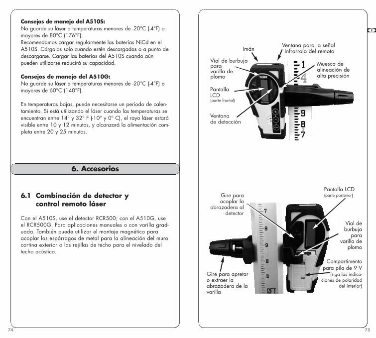
7574
GB F E D I N FIN NL
Consejos de manejo del A510S:No guarde su láser a temperaturas menores de -20°C (-4°F) omayores de 80°C (176°F). Recomendamos cargar regularmente las baterías NiCd en elA510S. Cárgalas solo cuando estén descargadas o a punto dedescargarse. Cargar las baterías del A510S cuando aúnpueden utilizarse reducirá su capacidad.
Consejos de manejo del A510G:No guarde su láser a temperaturas menores de -20°C (-4°F) omayores de 60°C (140°F).
En temperaturas bajas, puede necesitarse un período de calen-tamiento. Si está utilizando el láser cuando las temperaturas seencuentran entre 14° y 32° F (-10° y 0° C), el rayo láser estarávisible entre 10 y 12 minutos, y alcanzará la alimentación com-pleta entre 20 y 25 minutos.
6. Accesorios
6.1 Combinación de detector y control remoto láser
Con el A510S, use el detector RCR500; con el A510G, useel RCR500G. Para aplicaciones manuales o con varilla grad-uada. También puede utilizar el montaje magnético paraacoplar los espárragos de metal para la alineación del murocortina exterior o las rejillas de techo para el nivelado deltecho acústico.
PantallaLCD (parte frontal)
Muesca de alineación dealta precisión
Ventana de detección
ImánVentana para la señalinfrarroja del remoto
Vial de burbujapara varilla deplomo
Pantalla LCD(parte posterior)
Vial de burbuja
para varilla de
plomo
Compartimentopara pila de 9 V
(siga las indica-ciones de polaridad
del interior)
Gire paraacoplar la
abrazadera aldetector
Gire para apretaro extraer laabrazadera de lavarilla
A510S-jun2009.qxp 15/07/09 17:41 Page 74

7776
GB F E D I N FIN NL
Batería baja
Parpadeo: Volumen normal
Sólido: Volumen alto
Sin bocina: Silencio
Grueso Fino
Bajo
Nivel noalcanzado
Nivel óptimo
Nivelexcedido
Alto
ESATDO DE LABATERÍA
PRECISIÓN
• Pantalla LCD
• Modo detección
1. Pulse el botón de encendido/apagado para conectar eldetector.2. Pulse el botón central para seleccionar la precisión (bandainactiva).3. Pulse el botón superior para seleccionar el nivel de sonido.4. Gire la ventana de detección hacia el rayo láser y muevael detector hacia arriba o hacia abajo según la informaciónmostrada en la pantalla LCD. Existen 5 canales de informacióno indicadores de graduación.
Una flecha hacia abajo indica que debe mover el detectorhacia abajo para lograr la referencia del láser; una flechahacia arriba indica que lo haga hacia arriba. Cuandoaparece una línea horizontal en la pantalla, el detector seencuentra en el mismo nivel que el rayo láser.
5. Pulse el botón de encendido/apagado para desconectar eldetector. Se desconectará automáticamente tras 10 minutos deinactividad (y emitirá un pitido de advertencia).
SONIDO
(Estandard)
Elección del nivelde sonido
Mueve la captura
hacia la izquierda
Mueve la captura
hacia la derecha
Dirige el escaneo
hacia la izquierda
Dirige el escaneo
hacia la derecha
y se utilizan para la calibración o
para ajustar la graduación manual
Elección de laprecisión
Encendido/Apagado
• Botones superiores
Modo detector (botones rojos) Modo remoto Modo escaneado
• Botones inferiores
Aumenta la velocidadde rotación
Reduce la velocidadde rotación
Inicia el modo rotatorio
La sección de calibración del manual explicala función de los símbolos secundarios demenor tamaño.
RESOLUCIÓN DE PROBLEMAS
• Antes de usar el detector es muy importanteque el A510 este en modo de punto. Los recep-tores no pueden detectar el rayo si está en modolínea.• Si no puede levantar el rayo con el detector,compruebe de qué manera usted está alineadocon el laser. Uno de los soportes de protecciónprincipal ubicados en el láser pueden bloquear elrayo; y deberá mover hacia la izquierda o laderecha para recibir al rayo.• La protección principal de metal puede retirarsedel láser centrando las dos cerraduras de seguri-dad. Esto no afectará el funcionamiento o laresistencia al agua o polvo del láser.• Si está frío y no hay señal del A510G, permitatiempo para calentarse (ver sección Cuidado ymanejo).
Aumenta el ángulode escaneo
Reduce el ángulo de escaneo
Modo remoto Modo escaneado
A510S-jun2009.qxp 15/07/09 17:41 Page 76

7978
GB F E D I N FIN NL
6.3 Trípodes
El láser A510 puede ser montado en una cabeza con rosca5/8”. Usted también puede usar un trípode de columna ele-vadora.
Modo línea1.2. Disminuye lavelicidad de la rotación3. Aumenta la velicidadde la rotación4. Modo “punto apunto” desplaza a laizquierda5. Modo “punto apunto” desplaza a laderecha
Modo scan 1. Encendido/apagado2. Disminuye la distanciade exploración3. Aumenta la distanciade exploración4. Mueve scan hacia laizquierda
5. Mueve scan hacia laderecha
Modo soportemotorizado1. Presione 3 segundospara empezar el modo2. Mueve el láser haciaarriba3. Mueve el láser haciaabajo
Ventana infraroja
Pila AA
2
3
5
4
1
6. Mantenga limpia la ventana de detección con la ayuda deun paño suave y limpiacristales.
• Modo control remoto
El modo detector tiene que estar parado para poder utilizar elmando a distancia.
El remoto puede utilizarse para detener o iniciar la rotación, aumen-tar o reducir la velocidad de rotación y mover el rayo o la captura.También controla el escaneo y la calibración electrónica.
• Especificaciones
Rango* 150 m (500') en modo detección30 m (100') en modo remoto
Precisión* Fina ± 1 mm (<1/16")Gruesa ± 2.5 mm (1/8")
Duración de la pila 50 horas; alcalina de 9 VImpermeabilidad medioambiental (IP66)Tamaño 15 x 8 x 3,5 cm / 280 g**
(6" x 3.25"x 1.5"; 10 onzas**)
*Varía según el láser utilizado. La precisión actual depende del diámetro del
rayo y la distancia hasta el láser.
** Con baterías
6.2 Mando a distancia
El mando a distancia permite detener o comenzar la rotación delhaz de láser, así como mover el haz vertical a izquierda yderecha. También sirve para controlar la exploración y la cali-bración.
Una pila alcalina AA de 1,5 V garantiza 50 horas de uso continuo.Para abrir el compartimiento de la pila, presione hacia arriba lapestaña de la parte superior, en la dirección de la flecha, con undestornillador.
A510S-jun2009.qxp 15/07/09 17:41 Page 78

A510S / A510GBedienungsanleitung
80
6.4 Otros accesorios
1. Gafas para ampliación de luminosidad en caso de que lascondiciones de luz sean altas.2. Tarjeta magnética para ampliar la visibilidad del rayo encondiciones de luz altas. Contiene un imán para sujetarlo enzonas metálicas.
El A510 viene con una garantía de dos años de Agatec (en NorteAmérica, un año, y hasta 2 años con una inscripción en el internethasta 45 días después de la compra).Encontrará más información en: www.agatec.com
7. Garantía
A510S-jun2009.qxp 15/07/09 17:41 Page 80


![Biol 2202 - Web Site Project Final[1]](https://img.pdfslide.us/doc/110x75/586a2e701a28ab81568c32e0/biol-2202-web-site-project-final1.jpg)