Embed Size (px)
Citation preview
File name: Akribis AG300 - Hardware Manual - CTL V3, AMP V2 R1.2.docx Date: Thursday, April 28, 2016
Version: 1.1
Author: Sapir Eyal
Pages: 41
Page 1
AG300 Family
CTL01-3A-03, AMP01-2A-02
Hardware User's Manual
File name: Akribis AG300 - Hardware Manual - CTL V3, AMP V2 R1.2.docx Date: Thursday, April 28, 2016
Version: 1.1
Author: Sapir Eyal
Pages: 41
Page 2
Revision control table
Version Description Date
1.0 Initial (based on Hardware Manual of previous hardware
versions) April 27, 2016
1.1 Corrections and additions by Gregory April 28, 2016
1.2 Update USB driver URL Oct 13, 2016
File name: Akribis AG300 - Hardware Manual - CTL V3, AMP V2 R1.2.docx Date: Thursday, April 28, 2016
Version: 1.1
Author: Sapir Eyal
Pages: 41
Page 3
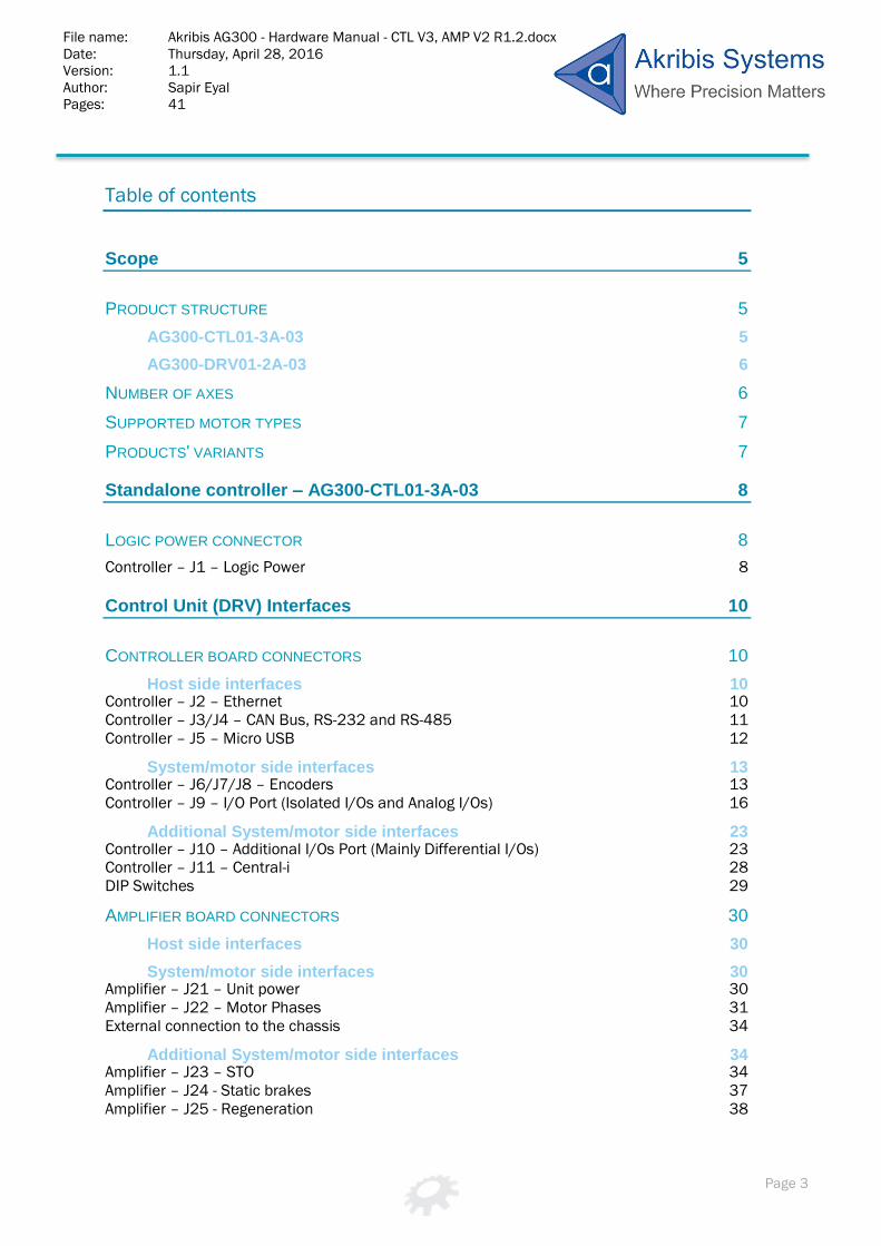
Table of contents
Scope 5
PRODUCT STRUCTURE 5
AG300-CTL01-3A-03 5
AG300-DRV01-2A-03 6
NUMBER OF AXES 6
SUPPORTED MOTOR TYPES 7
PRODUCTS' VARIANTS 7
Standalone controller – AG300-CTL01-3A-03 8
LOGIC POWER CONNECTOR 8
Controller – J1 – Logic Power 8
Control Unit (DRV) Interfaces 10
CONTROLLER BOARD CONNECTORS 10
Host side interfaces 10 Controller – J2 – Ethernet 10 Controller – J3/J4 – CAN Bus, RS-232 and RS-485 11 Controller – J5 – Micro USB 12
System/motor side interfaces 13 Controller – J6/J7/J8 – Encoders 13 Controller – J9 – I/O Port (Isolated I/Os and Analog I/Os) 16
Additional System/motor side interfaces 23 Controller – J10 – Additional I/Os Port (Mainly Differential I/Os) 23 Controller – J11 – Central-i 28 DIP Switches 29
AMPLIFIER BOARD CONNECTORS 30
Host side interfaces 30
System/motor side interfaces 30 Amplifier – J21 – Unit power 30 Amplifier – J22 – Motor Phases 31 External connection to the chassis 34
Additional System/motor side interfaces 34 Amplifier – J23 – STO 34 Amplifier – J24 - Static brakes 37 Amplifier – J25 - Regeneration 38

File name: Akribis AG300 - Hardware Manual - CTL V3, AMP V2 R1.2.docx Date: Thursday, April 28, 2016
Version: 1.1
Author: Sapir Eyal
Pages: 41
Page 4
Dimensions 40
AG300-CTL01-3A-03 STANDALONE CONTROLLER 40
AG300-CTL01 INTEGRATED CONTROL UNIT 40
Environmental conditions 41

File name: Akribis AG300 - Hardware Manual - CTL V3, AMP V2 R1.2.docx Date: Thursday, April 28, 2016
Version: 1.1
Author: Sapir Eyal
Pages: 41
Page 5
Scope
This manual describes hardware interfaces of the AG300-CTL01-3A-03 (version 3) as a
standalone controller and also as a complete control unit, when supplied as a drive, together
with the AG300-AMP01-2A-02 (version 2).
This manual describes hardware interfaces of the following products:
Product description Part numbers
Standalone controller AG300-CTL01-3A-03-XX (version 3)
Complete control unit (AG300-DRV01): Controller
+ amplifier
AG300-CTL01-3A-03-XX (version 3) +
AG300-AMP01-2A-02-XX (version 2)
The –XX defines a product's hardware variant, as describes below.
Product structure
AG300-CTL01-3A-03
The following picture shows the AG300-CTL01 controller board, as supplied for standalone
operation (to be used with external amplifiers):

File name: Akribis AG300 - Hardware Manual - CTL V3, AMP V2 R1.2.docx Date: Thursday, April 28, 2016
Version: 1.1
Author: Sapir Eyal
Pages: 41
Page 6
AG300-DRV01-2A-03
The following picture shows the AG300-DRV01-2A-03 control unit, which consists of the
AG300-CTL01-3A-03 (controller board, version 3) and the AG300-AMP01-2A-02 (amplifier
board, version 2). The DRV control unit is a full control unit, ready to connect directly to the
motors.
Number of axes
The AG300-CTL01-3A-03 (controller board) supports control and interfaces for up to 3 axes.
The AG300-AMP01-2A-02 (amplifier board) supports driving of up to 2 motors.
This means that the integrated control unit (controller + amplifier) can control and drive up to
2 motors. However, please note that since the controller board is a 3 axes controller, a third
axis can be controlled, if an external amplifier is connected (±10v command or
Pulse/Direction command).
System/Motor side
connectors
Additional
System/Motor
side connectors
Host side
connectors
Amplifier (AMP01)
board (lower)
Metal base
Controller (CTL01)
board (upper)

File name: Akribis AG300 - Hardware Manual - CTL V3, AMP V2 R1.2.docx Date: Thursday, April 28, 2016
Version: 1.1
Author: Sapir Eyal
Pages: 41
Page 7
Supported motor types
The AG300 control unit can control and drive the following motor types:
Up to 2 DC-Brushless, DC-Brush, Voice coil or Bipolar Stepper motors (each motor
defined independently).
Future firmware will also support, with no hardware change, control and driving of 3
Brush (or Voice coil) motors.
Linear and rotary motors are both supported.
Products' variants
The –XX at the end of the product's part number (see label on the product) defines the
product's variant.
For the controller:
AG300-CTL01-3A-03-36: Full variant.
All hardware interfaces are assembled and included.
For the amplifier:
AG300-AMP01-2A-02-02: Full variant for 20A Full Scale.
All hardware interfaces are assembled and included.
Up to 16A peak current.
Up to 8A continuous current.
AG300-AMP01-2A-02-03: Full variant for 10A Full Scale.
All hardware interfaces are assembled and included.
Up to 8A peak current.
Up to 4A continuous current.
AG300-AMP01-2A-02-04: Full variant for 5A Full Scale.
All hardware interfaces are assembled and included.
Up to 4A peak current.
Up to 2A continuous current.
File name: Akribis AG300 - Hardware Manual - CTL V3, AMP V2 R1.2.docx Date: Thursday, April 28, 2016
Version: 1.1
Author: Sapir Eyal
Pages: 41
Page 8
Standalone controller – AG300-CTL01-3A-03
This document provides a detailed description of all the interfaces of the overall (DRV) control
unit product (controller + amplifier). It does not provide a separate description of the
interfaces of the standalone controller, as these interfaces are already described as part of
the overall DRV product interfaces.
However, a single exception is the controller logic power connector, which is used only when
using the controller as a standalone product. The following section describes this connector.
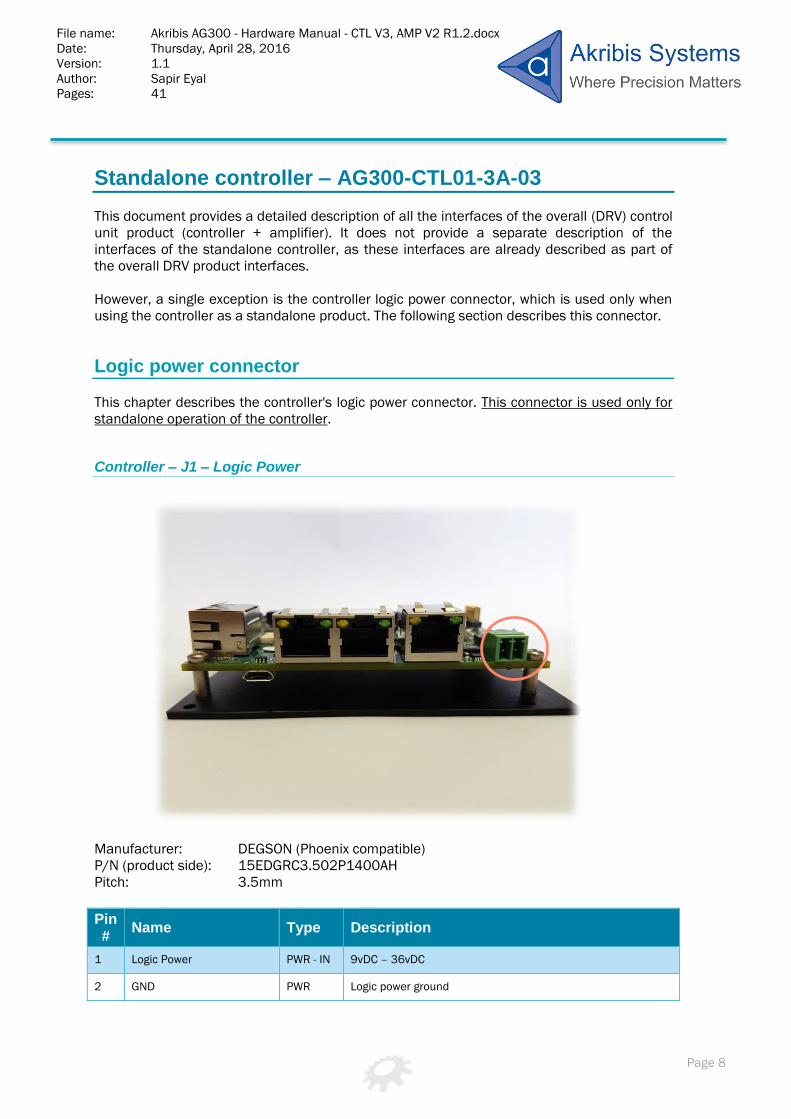
Logic power connector
This chapter describes the controller's logic power connector. This connector is used only for
standalone operation of the controller.
Controller – J1 – Logic Power
Manufacturer: DEGSON (Phoenix compatible)
P/N (product side): 15EDGRC3.502P1400AH
Pitch: 3.5mm
Pin #
Name Type Description
1 Logic Power PWR - IN 9vDC – 36vDC
2 GND PWR Logic power ground

File name: Akribis AG300 - Hardware Manual - CTL V3, AMP V2 R1.2.docx Date: Thursday, April 28, 2016
Version: 1.1
Author: Sapir Eyal
Pages: 41
Page 9
The controller includes a built-in protection to avoid damage in case of inversed polarity at the
input power.
Note – Warning!
Use this power connector only when using the controller board as a standalone product.

File name: Akribis AG300 - Hardware Manual - CTL V3, AMP V2 R1.2.docx Date: Thursday, April 28, 2016
Version: 1.1
Author: Sapir Eyal
Pages: 41
Page 10
Control Unit (DRV) Interfaces
The following sections provide detailed definition of the connectors and the electrical
interfaces of the controller board and the amplifier board when assembled as an integrated
control unit (DRV) product.
Controller board connectors
The chapter describes the connectors and interfaces of the controller board. This description
is relevant both for standalone operation of the controller board, or when used within a
complete control unit (DRV) with the amplifier board.
Host side interfaces
This section describes the connectors that are aimed to interface with the host computer
(communication interfaces).
Controller – J2 – Ethernet
Description: RJ45 LAN 10/100Base-T Connector with magnetic
Cable: CAT5

File name: Akribis AG300 - Hardware Manual - CTL V3, AMP V2 R1.2.docx Date: Thursday, April 28, 2016
Version: 1.1
Author: Sapir Eyal
Pages: 41
Page 11
Note – Ethernet is not supported yet:
The Ethernet communication is not supported yet. Avoid using this connector until it will be
supported (future firmware versions).
Controller – J3/J4 – CAN Bus, RS-232 and RS-485
Description: RJ-45 8 pin right angle dual port
Note – Why dual port connector?
The J3/J4 connector is a dual port RJ45 connector (one is J3 and one is J4). The two ports
have identical pinout and are interchangeable. Two ports are provided to support daisy chain
connection of CAN Bus or RS-485. It can be also used to connect two types of communication
channels at the same time, instead of splitting a cable from a single RJ45 connector.
Pin #
Name Type Description
1 GND PWR Reference ground
2 RS232_RX IN RS2-32 input (comes towards AG300)
3 RS232_TX Out RS-232 output (comes from AG300)
4 RS485_B In/Out RS-485 bus, inverted
5 RS485_A In/Out RS-485 bus, not inverted

File name: Akribis AG300 - Hardware Manual - CTL V3, AMP V2 R1.2.docx Date: Thursday, April 28, 2016
Version: 1.1
Author: Sapir Eyal
Pages: 41
Page 12
Pin #
Name Type Description
6 Sync In/Out Synchronization line (future use, consult Agito)
7 CAN_L In/Out CAN bus negative line
8 CAN_H In/Out CAN bus positive line
Notes – CAN Bus and RS-485 terminators:
The CAN Bus lines have optional 120 ohm terminator that is connected/disconnected by DIP
Switch number 1 (refer to the chapter about the DIP Switches). Place DIP Switch number 1 at
ON position to place a 120 ohms terminator on the lines (to be done at the last unit in the
chain).
The RS-485 lines have built-in, fixed (not optional) 120 ohms terminator. This may degrade
the communication performance in case too many units are placed on the RS-485 chain.
Please consult Agito in such case (in future versions this built-in RS-485 terminator may be
removed. In such case Agito will inform the customers in advance).
Controller – J5 – Micro USB
Description: CONN RCPT MICRO USB 2.0 B-Type
File name: Akribis AG300 - Hardware Manual - CTL V3, AMP V2 R1.2.docx Date: Thursday, April 28, 2016
Version: 1.1
Author: Sapir Eyal
Pages: 41
Page 13
Note: RS-232 Bridge:
The Micro USB connection is implemented using an internal bridge from USB to RS-232
(UART). As a result, the communication performance, from the point of view of the user, is
identical to RS-232, using a suitable software driver at the PC side.
For PC Software drivers, although in most cases they are automatically loaded, you may
follow the link: http://www.ftdichip.com/Drivers/CDM/CDM21224_Setup.zip
System/motor side interfaces
This section describes the connectors that are aimed to interface with the system side
(encoders, I/O's…).
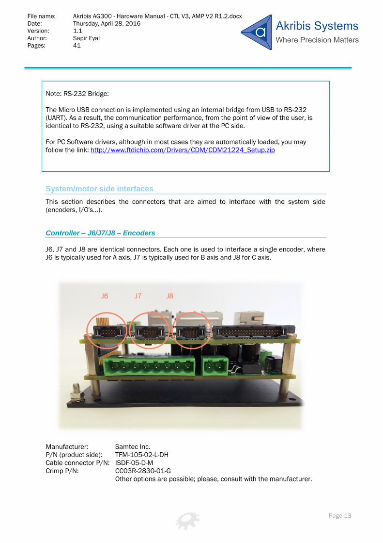
Controller – J6/J7/J8 – Encoders
J6, J7 and J8 are identical connectors. Each one is used to interface a single encoder, where
J6 is typically used for A axis, J7 is typically used for B axis and J8 for C axis.
Manufacturer: Samtec Inc.
P/N (product side): TFM-105-02-L-DH
Cable connector P/N: ISDF-05-D-M
Crimp P/N: CC03R-2830-01-G
Other options are possible; please, consult with the manufacturer.
J6 J7 J8

File name: Akribis AG300 - Hardware Manual - CTL V3, AMP V2 R1.2.docx Date: Thursday, April 28, 2016
Version: 1.1
Author: Sapir Eyal
Pages: 41
Page 14
Pin #
Name Type Description
1 5V PWR - OUT 5V for user usage (up to 0.5A, each connector)
2 GND PWR Reference for 5V and differential signals
3 Encoder_1P Out Differential output, not inverted
4 Encoder_1N Out Differential output, inverted
5 Encoder_2P In Differential input, not inverted
6 Encoder_2N In Differential input, inverted
7 Encoder_3P In Differential input, not inverted
8 Encoder_3N In Differential input, inverted
9 Encoder_4P Bidirectional Differential input/output, not inverted
10 Encoder_4N Bidirectional Differential input/output, inverted
Several encoder options are available. For each type of encoder, the inputs and outputs are
selected according to the table below:
Differential line
Incremental Sin/Cos SSI BiSS Nikon Tamagawa Panasonic
Encoder_1 OUT
Encoder_2 IN- A IN-SIN
Encoder_3 IN- B IN-COS IN IN IN
Encoder_4 IN- Z IN-Z OUT OUT INOUT INOUT OUT
Notes – Supported encoder types and connection of incremental encoder:
Currently only incremental encoder type is supported. SIN/COS analog encoders will soon be
supported as well, to be followed also with absolute encoders support.
Note (see table above) that the A. B and Z channels of the encoder are connected to
Encoder_2, Encoder_3 and Encoder_4 pins of the connector, respectively.

File name: Akribis AG300 - Hardware Manual - CTL V3, AMP V2 R1.2.docx Date: Thursday, April 28, 2016
Version: 1.1
Author: Sapir Eyal
Pages: 41
Page 15
Note – Incremental encoder interface details:
The internal design of the A, B and Z signals interfaces supports, by default, differential
inputs. However, with a dedicated assembly, it can support, without any external component,
also single ended encoders. Please consult Agito in case your application uses single ended
encoders or any other special, non-differential interface.
The default differential encoder's interface includes a built-in 120 ohms terminator (per each
channel) and also the required hardware circuits to detect disconnected encoder cable (and
in such case, the controller will disable the motor). The detection is done on the A and B
channels only (and not on the index, Z, channel)
Note: 5v supply limitation:
Note that the 5v supply that is provided at pin 1 of each of the J6, J7 and J8 connectors is
internally limited to 0.5A per each connector (independent limitation at each connector). This
is in order to protect the controller from short to GND.
Future firmware versions of the controller will be able to detect and report such fault and to
disable the 5v supply until the fault is fixed. Currently, the current will be limited, but the
detection of this limit and the shutting off of the 5v supply is not supported yet.
File name: Akribis AG300 - Hardware Manual - CTL V3, AMP V2 R1.2.docx Date: Thursday, April 28, 2016
Version: 1.1
Author: Sapir Eyal
Pages: 41
Page 16
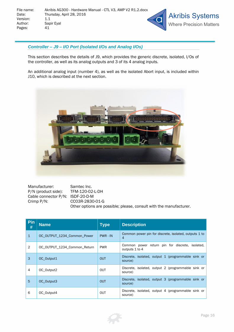
Controller – J9 – I/O Port (Isolated I/Os and Analog I/Os)
This section describes the details of J9, which provides the generic discrete, isolated, I/Os of
the controller, as well as its analog outputs and 3 of its 4 analog inputs.
An additional analog input (number 4), as well as the isolated Abort input, is included within
J10, which is described at the next section.
Manufacturer: Samtec Inc.
P/N (product side): TFM-120-02-L-DH
Cable connector P/N: ISDF-20-D-M
Crimp P/N: CC03R-2830-01-G
Other options are possible; please, consult with the manufacturer.
Pin #
Name Type Description
1 OC_OUTPUT_1234_Common_Power PWR - IN Common power pin for discrete, isolated, outputs 1 to
4
2 OC_OUTPUT_1234_Common_Return PWR Common power return pin for discrete, isolated,
outputs 1 to 4
3 OC_Output1 OUT Discrete, isolated, output 1 (programmable sink or
source)
4 OC_Output2 OUT Discrete, isolated, output 2 (programmable sink or
source)
5 OC_Output3 OUT Discrete, isolated, output 3 (programmable sink or
source)
6 OC_Output4 OUT Discrete, isolated, output 4 (programmable sink or
source)

File name: Akribis AG300 - Hardware Manual - CTL V3, AMP V2 R1.2.docx Date: Thursday, April 28, 2016
Version: 1.1
Author: Sapir Eyal
Pages: 41
Page 17
Pin #
Name Type Description
7 OC_INPUT_1234_Common PWR - IN Common pin (power or return, depending on external
connection) for discrete, isolated, inputs 1 to 4
8 OC_INPUT_5678_Common PWR - IN Common pin (power or return, depending on external
connection) for discrete, isolated, inputs 1 to 4
9 OC_Input1 IN Discrete, isolated, input 1 (NPN or PNP, depending on
connection of the common pin of this group)
10 OC_Input2 IN Discrete, isolated, input 2 (NPN or PNP, depending on
connection of the common pin of this group)
11 OC_Input3 IN Discrete, isolated, input 3 (NPN or PNP, depending on
connection of the common pin of this group)
12 OC_Input4 IN Discrete, isolated, input 4 (NPN or PNP, depending on
connection of the common pin of this group)
13 OC_Input5 IN Discrete, isolated, input 5 (NPN or PNP, depending on
connection of the common pin of this group)
14 OC_Input6 IN Discrete, isolated, input 6 (NPN or PNP, depending on
connection of the common pin of this group)
15 OC_Input7 IN Discrete, isolated, input 7 (NPN or PNP, depending on
connection of the common pin of this group)
16 OC_Input8 IN Discrete, isolated, input 8 (NPN or PNP, depending on
connection of the common pin of this group)
17 OC_Input9 (*) IN Discrete, isolated, input 9 (NPN or PNP, depending on
connection of the common pin of this group)
18 OC_INPUT_91011_Common PWR - IN Common pin (power or return, depending on external
connection) for discrete, isolated, inputs 9 to 11
19 OC_Input11 (*) IN Discrete, isolated, input 11 (NPN or PNP, depending on
connection of the common pin of this group)
20 OC_Input10 (*) IN Discrete, isolated, input 10 (NPN or PNP, depending on
connection of the common pin of this group)
21 5V_IO PWR - OUT 5v supply for external I/O circuits. Limited to 0.5A, pins
21 and 23 together.
22 GND PWR GND for 5V and differential signals
23 5V_IO PWR - OUT 5v supply for external I/O circuits. Limited to 0.5A, pins
21 and 23 together.
24 GND PWR GND for 5V and differential signals
25 +VA (15V) PWR – OUT Low current +15v supply for external analog circuits
26 -VA (-15V) PWR – OUT Low current +15v supply for external analog circuits
27 Analog_ Output1 OUT Analog output 1, ±12v, 16 bit
28 Analog_Output_Return_1 OUT Analog output 1 return (internally connected to GND
29 Analog_ Output2 OUT Analog output 2, ±12v, 16 bit

File name: Akribis AG300 - Hardware Manual - CTL V3, AMP V2 R1.2.docx Date: Thursday, April 28, 2016
Version: 1.1
Author: Sapir Eyal
Pages: 41
Page 18
Pin #
Name Type Description
30 Analog_Output_Return_2 OUT Analog output 2 return (internally connected to GND
31 Analog_ Output3 OUT Analog output 3, ±12v, 16 bit
32 Analog_Output_Return_3 OUT Analog output 3 return (internally connected to GND
33 Analog_ Output4 OUT Analog output 4, ±12v, 16 bit
34 Analog_Output_Return_4 OUT Analog output 4 return (internally connected to GND
35 Analog_Input1 IN Analog input 1, , ±12v, 12 bit
36 Analog_Input_Return_1 IN Analog input 1 return
37 Analog_Input2 IN Analog input 2, , ±12v, 12 bit
38 Analog_Input_Return_2 IN Analog input 2 return
39 Analog_Input3 IN Analog input 3, , ±12v, 12 bit
40 Analog_Input_Return_3 IN Analog input 3 return
(*) The organization of the pins for discrete, isolated, inputs 9 to 11 is different from the
organization for the groups of inputs 1 to 4 and inputs 5 to 8. This is not a documentation
mistake. Indeed the organization is different.
Note – Analog output are not supported in some of the product variants:
Some variants of the product do not support the analog outputs. Please consult Agito for
ordering the correct variant in case you need analog outputs for your application.
Analog outputs are required in case you need to interface external amplifier over a ±10v
analog command, or in case you need analog output for any other general purpose.
Note: 5v supply limitation:
Note that the 5v supply that is provided on pins 21 and 23 is internally limited to 0.5A (both
pins together). This is in order to protect the controller from short to GND.
Future firmware version of the controller will be able to detect and report this fault and to
disable the 5v supply until the fault is fixed. Currently, the current will be limited, but the
detection of this limit and the shutting off of the 5v supply is not supported yet.

File name: Akribis AG300 - Hardware Manual - CTL V3, AMP V2 R1.2.docx Date: Thursday, April 28, 2016
Version: 1.1
Author: Sapir Eyal
Pages: 41
Page 19
Electrical interfaces – Discrete, Isolated, outputs:
The interface circuit is identical for outputs 2 to 4.
Each output can be programmed (by a software parameter) to act as a current
sourcing output (up to 300mA) or as a current sinking output (up to 500mA).
Common power is shared by all 4 outputs.
Common power can go up to 45 volts. Yet, typical usage should be limited by 36v.

File name: Akribis AG300 - Hardware Manual - CTL V3, AMP V2 R1.2.docx Date: Thursday, April 28, 2016
Version: 1.1
Author: Sapir Eyal
Pages: 41
Page 20
Electrical interfaces – Discrete, Isolated, inputs:
The interface circuit is identical for inputs 1 to 4, which are organized as a single
group.
Similarly, inputs 5-8 are organized as a group with an identical interface circuits and
inputs 9-11 are a third independent group.
Each group is fully isolated and independent of the other groups.
Each group can be connected as NPN or PNP interfaces, depending on the wiring of
the group common pin. If the common pin is connected to power (5v to 28v), then the
inputs of this group can be used with external NPN devices (external current sinking
devices). If the common is connected to the GND of some external power, then the
inputs can be used with external PNP devices (external current sourcing devices).
Note that the input circuit of the opto couplers includes two diodes. This enables the
usage as NPN of PNP.

File name: Akribis AG300 - Hardware Manual - CTL V3, AMP V2 R1.2.docx Date: Thursday, April 28, 2016
Version: 1.1
Author: Sapir Eyal
Pages: 41
Page 21
Clearly, one group can be wired to interface external NPN devices and another group
can be wired to interface PNP devices. However, within a group, all interfaces should
be the same, as they are based on the connection of the group common pin.
Electrical interfaces – Analog outputs:
The electrical interfaces of analog outputs 2 to 4 are identical to those of analog
output 1.
The analog outputs are -12v to +12v, 16 bits.
Output resistance is 10ohms.
Output current is up to ±2mA, without internal current limitation.
Analog outputs are controlled by the controller software in few operational modes:
Analog command to external amplifier.
Analog output controlled by the user for any generic purpose.
Analog output reflects the internal value of a user selected parameter
(position, position error, velocity, current and actually any parameter/status of
the controller), with a user defined scaling, for easy monitoring usin an
oscilloscope.

File name: Akribis AG300 - Hardware Manual - CTL V3, AMP V2 R1.2.docx Date: Thursday, April 28, 2016
Version: 1.1
Author: Sapir Eyal
Pages: 41
Page 22
Electrical interfaces – Analog inputs:
The electrical interfaces of analog inputs 2 to 4 are identical to those of analog input
1.
The analog inputs are -12v to +12v, 12 bits.
The input circuit drawing is quite complex, in order to optionally support variety of
analog input sources. However, the default assembly (see yellow mark) is for standard
differential analog input, with a simple input circuit, having an input resistance of
~60K ohms.
Input circuit bandwidth: 1KHz, -40 db/dec.
For dedicated (non-differential) analog input formats, as shown in the above table, or
for any other type, please consult Agito for dedicated hardware variants of the
product.
The controller software provides parameters to control the analog input reading, as
follows:
Filter.
Offset.
Dead band.
Gain.

File name: Akribis AG300 - Hardware Manual - CTL V3, AMP V2 R1.2.docx Date: Thursday, April 28, 2016
Version: 1.1
Author: Sapir Eyal
Pages: 41
Page 23
Additional System/motor side interfaces
This section describes the additional connectors that are aimed to interface with the system
side (additional I/O's…).
Controller – J10 – Additional I/Os Port (Mainly Differential I/Os)
This section describes the details of J10, which provides the generic discrete, differential,
I/Os of the controller, as well as the 4th analog input and the discrete, isolated, Abort input.
Manufacturer: Samtec Inc.
P/N (product side): TFM-115-02-L-DH
Cable connector P/N: ISDF-15-D-M
Crimp P/N: CC03R-2830-01-G
Other options are possible; please, consult with the manufacturer.
Pin #
Name Type Description
1 Analog_Input4 IN Analog input 4, , ±12v, 12 bit
2 Analog_Input_Return_4 IN Analog input 4 return
3 OC_Abort+ (*) IN Discrete, isolated, Abort input, pin 1
4 OC_Abort- (*) IN Discrete, isolated, Abort input, pin 2
5 Diff_Input_P1 IN Differential input 1, positive pin
6 Diff_Input_N1 IN Differential input 1, negative pin

File name: Akribis AG300 - Hardware Manual - CTL V3, AMP V2 R1.2.docx Date: Thursday, April 28, 2016
Version: 1.1
Author: Sapir Eyal
Pages: 41
Page 24
Pin #
Name Type Description
7 Diff_Input_P2 IN Differential input 2, positive pin
8 Diff_Input_N2 IN Differential input 2, negative pin
9 Diff_Input_P3 IN Differential input 3, positive pin
10 Diff_Input_N3 IN Differential input 3, negative pin
11 Diff_Input_P4 IN Differential input 4, positive pin
12 Diff_Input_N4 IN Differential input 4, negative pin
13 Diff_Input_P5 IN Differential input 5, positive pin
14 Diff_Input_N5 IN Differential input 5, negative pin
15 Diff_Input_P6 IN Differential input 6, positive pin
16 Diff_Input_N6 IN Differential input 6, negative pin
17 Diff_Input_P7 IN Differential input 7, positive pin
18 Diff_Input_N7 IN Differential input 7, negative pin
19 Diff_Input_P8 IN Differential input 8, positive pin
20 Diff_Input_N8 IN Differential input 8, negative pin
21 Diff_Output_P1 OUT Differential output 1, positive pin
22 Diff_Output_N1 OUT Differential output 1, negative pin
23 Diff_Output_P1 OUT Differential output 2, positive pin
24 Diff_Output_N1 OUT Differential output 2, negative pin
25 Diff_Output_P1 OUT Differential output 3, positive pin
26 Diff_Output_N1 OUT Differential output 3, negative pin
27 Diff_Output_P1 OUT Differential output 4, positive pin
28 Diff_Output_N1 OUT Differential output 4, negative pin
29 GND PWR GND for the differential I/Os
30 GND PWR GND for the differential I/Os
(*) The Abort input is a software safety mechanism, to disable all motors, by software. The
motors are disabled when there is no current at this specific input and the user has no
access to bypass this logic. However, at the moment, this feature is not supported and the
Abort input is considered, by the software, just as any other discrete, isolated input.
Still, the user can define, by software parameters, that any of the inputs can be used to
automatically disable any motor, with a programmable logic (active high or active low).
File name: Akribis AG300 - Hardware Manual - CTL V3, AMP V2 R1.2.docx Date: Thursday, April 28, 2016
Version: 1.1
Author: Sapir Eyal
Pages: 41
Page 25
The Abort input functionality, as described above, will be added as part of one of the
controller firmware future versions.
Electrical interfaces – Analog input:
Please refer to the previous section (J9 connector).
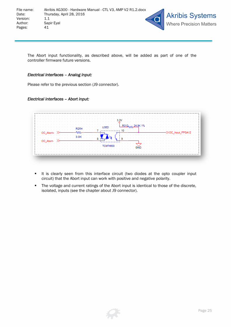
Electrical interfaces – Abort input:
It is clearly seen from this interface circuit (two diodes at the opto coupler input
circuit) that the Abort input can work with positive and negative polarity.
The voltage and current ratings of the Abort input is identical to those of the discrete,
isolated, inputs (see the chapter about J9 connector).

File name: Akribis AG300 - Hardware Manual - CTL V3, AMP V2 R1.2.docx Date: Thursday, April 28, 2016
Version: 1.1
Author: Sapir Eyal
Pages: 41
Page 26
Electrical interfaces – Differential inputs:
The electrical interfaces of differential inputs 5 to 8 are identical to those of inputs 1
to 4.
Note that each differential input has 120 ohms terminator.
Note that each differential input has pull-up to 3.3V on its positive pin and pull down
to GND on is negative pin. This ensures that the input is not floating when not
connected and that its reading is known and fixed.
Note that the negative input pin, on each differential input, has also a pull-up to 3.3V.
This enables the usage of a differential input with a single-ended source, by
connecting it to the positive input only and leaving the negative pin disconnected.
The differential inputs can be used with 5v differential sources.

File name: Akribis AG300 - Hardware Manual - CTL V3, AMP V2 R1.2.docx Date: Thursday, April 28, 2016
Version: 1.1
Author: Sapir Eyal
Pages: 41
Page 27
Electrical interfaces – Differential outputs:
The differential outputs are disabled immediately after power on, till they are
controlled by the software and the user defined parameters.

File name: Akribis AG300 - Hardware Manual - CTL V3, AMP V2 R1.2.docx Date: Thursday, April 28, 2016
Version: 1.1
Author: Sapir Eyal
Pages: 41
Page 28
Controller – J11 – Central-i
This connected is for a future functionality of the controller. In some variants of the product it
is not even assembled. Please do not use this connector.
Description: CONN RJ45 8P8C R/A SHLD, LEDs

File name: Akribis AG300 - Hardware Manual - CTL V3, AMP V2 R1.2.docx Date: Thursday, April 28, 2016
Version: 1.1
Author: Sapir Eyal
Pages: 41
Page 29
DIP Switches
The controller board includes 8 DIP switches as shown in the following figure:
The DIP switches have few future purposes, such as defining the address offset of the unit
over a CAN Bus or RS-485 daisy chain connections and also some other internal purposes.
These features will be supported within future firmware versions.
Please keep, at all times, DIP Switches 2 to 8 at OFF state.
DIP Switch 1 has a dedicated function. It places a 120 ohms terminator on the CAN bus lines
when the DIP Switch is in its ON position and disconnects the terminator when the switch is
at its OFF position.
The state of this switch is important only if you use CAN Bus communication. In such case,
the last unit in the chain should have this DIP Switch at ON position, while all other units
should have it at OFF position.

File name: Akribis AG300 - Hardware Manual - CTL V3, AMP V2 R1.2.docx Date: Thursday, April 28, 2016
Version: 1.1
Author: Sapir Eyal
Pages: 41
Page 30
Amplifier board connectors
The chapter describes the connectors and interfaces of the amplifier board.
Host side interfaces
No connectors at this side. The amplifier is not interfacing with the Host.
System/motor side interfaces
This section describes the connectors that are aimed to interface with the system side (unit
power, motor phases…).
Amplifier – J21 – Unit power
J21 is used to supply power to the overall unit. The input voltage is directly connected to the
amplifier power bridge, to driver the motors, and in parallel it is used to generate internal
logic power in order to power the controller board.
The control unit is fully operational with this single power supply.
Note – Optional schemes for isolated power supplies:
The AG300 controller and amplifier are designed to support fully isolated power supplies, one
for the amplifier and the motor and one for the controller. Such operation requires a
dedicated hardware variant. Please consult Agito in case you would like to consider this
scheme.
The amplifier includes a protection to avoid damage in case of inversed polarity at the input
power.

File name: Akribis AG300 - Hardware Manual - CTL V3, AMP V2 R1.2.docx Date: Thursday, April 28, 2016
Version: 1.1
Author: Sapir Eyal
Pages: 41
Page 31
Manufacturer: DEGSON (Phoenix compatible)
P/N (product side): 2EDGRC5.0802P14H
Pitch: 5.08mm
Pin #
Name Type Description
1 Power GND PWR Power GND
2 Main Power PWR Motor power input: 12V to 90V, up to 16A continuous
Amplifier – J22 – Motor Phases
J22 is used to connect to the motors' phases. Connection depends on the motor type, as
described below.
Manufacturer: DEGSON (Phoenix compatible)
P/N (product side): 2EDGRC5.0808P14H
Pitch: 5.08mm
Pin 1

File name: Akribis AG300 - Hardware Manual - CTL V3, AMP V2 R1.2.docx Date: Thursday, April 28, 2016
Version: 1.1
Author: Sapir Eyal
Pages: 41
Page 32
For two Brushless motors:
Pin #
Name Type Description
1 Motor A Phase A PWR
2 Motor A Phase B PWR
3 Motor A Phase C PWR
4 Chassis Chassis Use for screening of the motor cable
5 Chassis Chassis Use for screening of the motor cable
6 Motor B Phase A PWR
7 Motor B Phase B PWR
8 Motor B Phase C PWR
For two Brush (or voice coil) motors:
Pin #
Name Type Description
1 Motor A Phase + PWR
2 Motor A Phase - PWR
3 NC PWR Do not connect
4 Chassis Chassis Use for screening of the motor cable
5 Chassis Chassis Use for screening of the motor cable
6 Motor B Phase + PWR
7 Motor B Phase - PWR
8 NC PWR Do not connect
For two Stepper motors:
Pin #
Name Type Description
1 Motor A Phase 1 + PWR
2 Motor A Phase 2 + PWR
3 Motor A Phases 1 and 2 - PWR Two motor wires are connected to a single pin of the connector
4 Chassis Chassis Use for screening of the motor cable
5 Chassis Chassis Use for screening of the motor cable

File name: Akribis AG300 - Hardware Manual - CTL V3, AMP V2 R1.2.docx Date: Thursday, April 28, 2016
Version: 1.1
Author: Sapir Eyal
Pages: 41
Page 33
Pin #
Name Type Description
6 Motor B Phase 1 + PWR
7 Motor B Phase 2 + PWR
8 Motor A Phases 1 and 2 - PWR Two motor wires are connected to a single pin of the connector
Note – Stepper voltage range:
Note that a bipolar stepper motor has two independent phases (total of 4 wires). With the
AG300-AMP01, you need to connect the (-) wire of both phases together, into the third pin of
the connector (for motor A) or the 8th pin (for motor B).
This connection implies a limitation of the voltage that will be applied to the stepper. For
example, if the power supply to the unit is 24v, each phase of the stepper motor will be
limited to 12v.
With suitable selection of the power supply this should impose no limitation on the stepper
motor operation.
User may connect different types of motors to motor A and to motor B. Just follow the above
instructions for each motor, independently.
In the future, the product will also support controlling and driving of three Brush (or Voice coil)
motors, with no hardware change.

File name: Akribis AG300 - Hardware Manual - CTL V3, AMP V2 R1.2.docx Date: Thursday, April 28, 2016
Version: 1.1
Author: Sapir Eyal
Pages: 41
Page 34
External connection to the chassis
The AG300 unit is equipped with a screw on the product's base, aimed for chassis connection
(power supply cable, shielding of other cables, etc.)m as shown in the following figure:
The chassis, within the product, is not connected to the power supply ground.
Additional System/motor side interfaces
This section describes the additional connectors that are aimed to interface with the system
side (STO, Static brakes and regeneration).
Amplifier – J23 – STO

File name: Akribis AG300 - Hardware Manual - CTL V3, AMP V2 R1.2.docx Date: Thursday, April 28, 2016
Version: 1.1
Author: Sapir Eyal
Pages: 41
Page 35
Manufacturer: Samtec Inc.
P/N (product side): TFM-104-02-L-DH
Cable connector P/N: ISDF-04-D-M
Crimp P/N: CC03R-2830-01-G
Other options are possible; please, consult with the manufacturer.
Pin #
Name Type Description
1 STO1- IN Safe Torque Off 1 negative input
2 STO1+ IN Safe Torque Off 1 positive input
3 STO2- IN Safe Torque Off 2 negative input
4 STO2+ IN Safe Torque Off 2 positive input
5 STOFB- OUT Safe Torque Off 1 negative (emitter) output
6 STOFB+ OUT Safe Torque Off 1 positive (collector) output
7 5v PWR - OUT 5v supply for STO circuits
8 GND PWR GND
Notes – STO Implementation:
STO1 and STO2 are completely independent. Each one of them disables the power to
the motor in a different way.
Both STO1 and STO2 disable the power to the motor by hardware circuitry, without
any software intervention.
The circuitry, logic and redundancy of the STO implementation were done according to
safety standards. Yet, the design is to be tested and formally approved for the
industry standard.
The STO1 and STO2 are defined with a positive pin (+) and a negative pin (-). However
(refer to the electrical interfaces described below) the opto coupler at the STO input
(as for all other discrete, isolated inputs of the AG300) is equipped with two input
diodes, enabling operation at "positive" or "negative" input voltage. The input is
actually activated by (enough) current at one of the input diodes, independently of the
current direct. This enables NPN or PNP connection to the STO inputs (each one of
them independently!).
The STO protection logic is designed so that the STO inputs (both of them) must be
powered in order to enable motor operation. Leaving an STO input disconnected will
prevent motor operation. This logic is required in order to ensure that a disconnected
safety cable will be considered by the control unit as an unsafe situation. When

File name: Akribis AG300 - Hardware Manual - CTL V3, AMP V2 R1.2.docx Date: Thursday, April 28, 2016
Version: 1.1
Author: Sapir Eyal
Pages: 41
Page 36
(enough) current is driven through an STO input, the state of this input is "safe". When
no (not enough) current is driven through an STO input, the state of this input is
"unsafe".
The two STO inputs must be at "safe" state in order to enable motor operation.
Both STO1 and STO2, although acting on the drive hardware directly, are also sensed
by the controller software. The controller software is generating a feedback signal to
the user (STO_FB) which is also an isolated signal. This feedback is generated by the
software and is activated in case a least one of STO1 or STO2 signals unsafe
situation.
Electrical interfaces – STO:
The electrical characteristics of the STO1 and STO2 inputs are identical to those of
the discrete, isolated inputs of the controller. Refer to the chapter about J9 above.

File name: Akribis AG300 - Hardware Manual - CTL V3, AMP V2 R1.2.docx Date: Thursday, April 28, 2016
Version: 1.1
Author: Sapir Eyal
Pages: 41
Page 37
Amplifier – J24 - Static brakes
Manufacturer: DEGSON (Phoenix compatible)
P/N (product side): 15EDGRC3.504P1400AH
Pitch: 3.5mm
Pin #
Name Type Description
1 Brake_Power PWR – IN Power supply for the brake isolated circuits in the controller. Up
to 48vDC.
2 A_Static_Brake PWR
Static brake output for motor A. Open-drain output with built-in
flyback diode to the Brake_Power for direct connection into
inductive load. Up to 4A operation.
3 B_Static_Brake PWR
Static brake output for motor B. Open-drain output with built-in
flyback diode to the Brake_Power for direct connection into
inductive load. Up to 4A operation.
4 Brake_Power_RTN PWR Return pin for the Brake_Power.
Note – Static Brake not supported yet:
The AG300 controller firmware does not support the operation of the static brake outputs yet.
This feature will be added soon, without any hardware change.
Electrical interfaces – static brakes:
Pin 1

File name: Akribis AG300 - Hardware Manual - CTL V3, AMP V2 R1.2.docx Date: Thursday, April 28, 2016
Version: 1.1
Author: Sapir Eyal
Pages: 41
Page 38
Amplifier – J25 - Regeneration
Manufacturer: DEGSON (Phoenix compatible)
P/N (product side): 2EDGRC5.0803P14H
Pitch: 5.08mm
Pin 1

File name: Akribis AG300 - Hardware Manual - CTL V3, AMP V2 R1.2.docx Date: Thursday, April 28, 2016
Version: 1.1
Author: Sapir Eyal
Pages: 41
Page 39
Pin #
Name Type Description
1 Internal DC Bus PWR – OUT
The internal DC Bus power (the same as the main power
supply, see J21, but after the circuit of inversed polarity
protection).
2 Regeneration PWR
Regeneration pin to be connected to an external
regeneration resistor. Limited to 16A.
The external regeneration resistor should be connected
between this pin (pin 2) and the Internal DC Bus pin (pin
1).
3 Power GND PWR
The return line for VIN. Do not connect/use this pin for the
regeneration function (it is not required for the
Regeneration implementation). In future versions of this
product (and in similar products from Agito) the
Regeneration connector will be a two pins connector and
this pin will be removed.
Note –Regeneration function not supported yet:
The AG300 controller firmware does not support the operation of the regeneration function
yet. This feature will be added soon, without any hardware change.
Electrical interfaces - Regeneration:

File name: Akribis AG300 - Hardware Manual - CTL V3, AMP V2 R1.2.docx Date: Thursday, April 28, 2016
Version: 1.1
Author: Sapir Eyal
Pages: 41
Page 40
Dimensions
This chapter provides the mechanical dimensions of the controller and of the integrated
control unit.
Note – Metal base:
Both the controller board as a standalone product and the integrated control unit (controller +
amplifier boards) are supplied with a metal base, for easy mounting, for protection of the
back of the product and for chassis connection.
Please consult Agito in case you prefer to use the product without this metal base to reduce
its overall dimensions (typically if the product is anyhow assembled on a metal base which is
part of the machine).
AG300-CTL01-3A-03 standalone controller
The following figures present the dimensions of the AG300-CTL01-3A-03 when supplied as a
standalone controller board.
<To Be Completed Soon>
AG300-CTL01 integrated control unit
The following figures present the dimensions of the AG300-CTL01 integrated control unit
(controller board plus amplifier board).
<To Be Completed Soon>

File name: Akribis AG300 - Hardware Manual - CTL V3, AMP V2 R1.2.docx Date: Thursday, April 28, 2016
Version: 1.1
Author: Sapir Eyal
Pages: 41
Page 41
Environmental conditions
Requirement Units Allowed range
Operational temperature C 0 to 50
Storage temperature C -20 to 70
Humidity % <90