Embed Size (px)
Citation preview
JOHN DEEREAG & TURF DIVISION
GX24537
G2
John Deere Tractors100 Series
OMGX24537 G2
OPERATOR’S MANUAL
North American VersionPrinted in U.S.A.
Original InstructionAll information, illustrations and
specifications in this manual are based on the latest information at the time of
publication. The right is reserved to make changes at any time without notice.
COPYRIGHT© 2012Deere & Co.
John Deere Worldwide Commercial and Consumer Equipment Division
All rights reservedPrevious Editions
COPYRIGHT© 2009, 2010, 2011
c WARNING: The Engine Exhaust from this product contains chemicals known to the State of California to cause cancer, birth defects or other reproductive harm.
California Proposition 65 Warning
Introduc
INTRODUCTION
Table of ContentsIntroduction................................................................................................ 1
Product Identification................................................................................. 1
Safety Labels............................................................................................. 3
Safety ........................................................................................................ 9
Machine Cleanout ................................................................................... 14
Assembly................................................................................................. 16
Operating Controls .................................................................................. 18
Operating................................................................................................. 21
Service Intervals...................................................................................... 31
Service Lubrication.................................................................................. 32
Service Engine ........................................................................................ 33
Service Transmission ............................................................................. 39
Service Mower......................................................................................... 39
Service Electrical..................................................................................... 44
Service Miscellaneous ............................................................................ 46
Troubleshooting ....................................................................................... 50
Storage.................................................................................................... 52
Specifications .......................................................................................... 53
Warranty.................................................................................................. 55
Index........................................................................................................ 57
Getting Quality Service ........................................................................... 58
Service Record........................................................................................ 59
IntroductionThank You for Purchasing a John Deere ProductWe appreciate having you as a customer and wish you many years of safe and satisfied use of your machine.
Using Your Operator’s ManualThis manual is an important part of your machine and should remain with the machine when you sell it.
Reading your operator’s manual will help you and others avoid personal injury or damage to the machine. Information given in this manual will provide the operator with the safest and most effective use of the machine. Knowing how to operate this machine safely and correctly will allow you to train others who may operate this machine.
This manual and safety signs on your machine may also be available in other languages (see your authorized dealer to order).
Sections in your operator’s manual are placed in a specific order to help you understand all the safety messages and learn the controls so you can operate this machine safely. You can also use this manual to answer any specific operating or servicing questions.
The machine shown in this manual may differ slightly from your machine, but will be similar enough to help you understand our instructions.
RIGHT-HAND and LEFT-HAND sides are determined by facing in the direction the machine will travel when going forward. When you see a broken line (------), the item referred to is hidden from view.
Before delivering this machine, your dealer performed a predelivery inspection to ensure best performance.
Special MessagesYour manual contains special messages to bring attention to potential safety concerns, machine damage as well as helpful operating and servicing information. Please read all the information carefully to avoid injury and machine damage.
NOTE: General information is given throughout the manual that may help the operator in the operation or service of the machine.
Product IdentificationRecord Identification Numbers
Lawn Tractors
D105, D110, D120, D130, D140, D160, D170
PIN (D400001-) 49 State
PIN (D040001-) California
PIN (D070001-) Australia, Canada, Mexico, ROW.
If you need to contact an Authorized Service Center for information on servicing, always provide the product model and identification numbers.
You will need to locate the product identification number (PIN) for the
c CAUTION: Avoid injury! This symbol and text highlight
potential hazards or death to the operator or bystanders that may occur if the hazards or procedures are ignored.
IMPORTANT: Avoid damage! This text is used to tell the operator of actions or conditions that might result in damage to the machine.
tion - 1
PRODUCT IDENTIFICATION
machine and engine serial number. Record the information in the spaces provided below.DATE OF PURCHASE:
_________________________________________
DEALER NAME:
_________________________________________
DEALER PHONE:
_________________________________________
PRODUCT IDENTIFICATION NUMBER:
__ __ __ __ __ __ __ __ __ __ __ __ __ __ __ __ __
ENGINE SERIAL NUMBER:
__ __ __ __ __ __ __ __ __ __ __ __ __ __ __ __ __
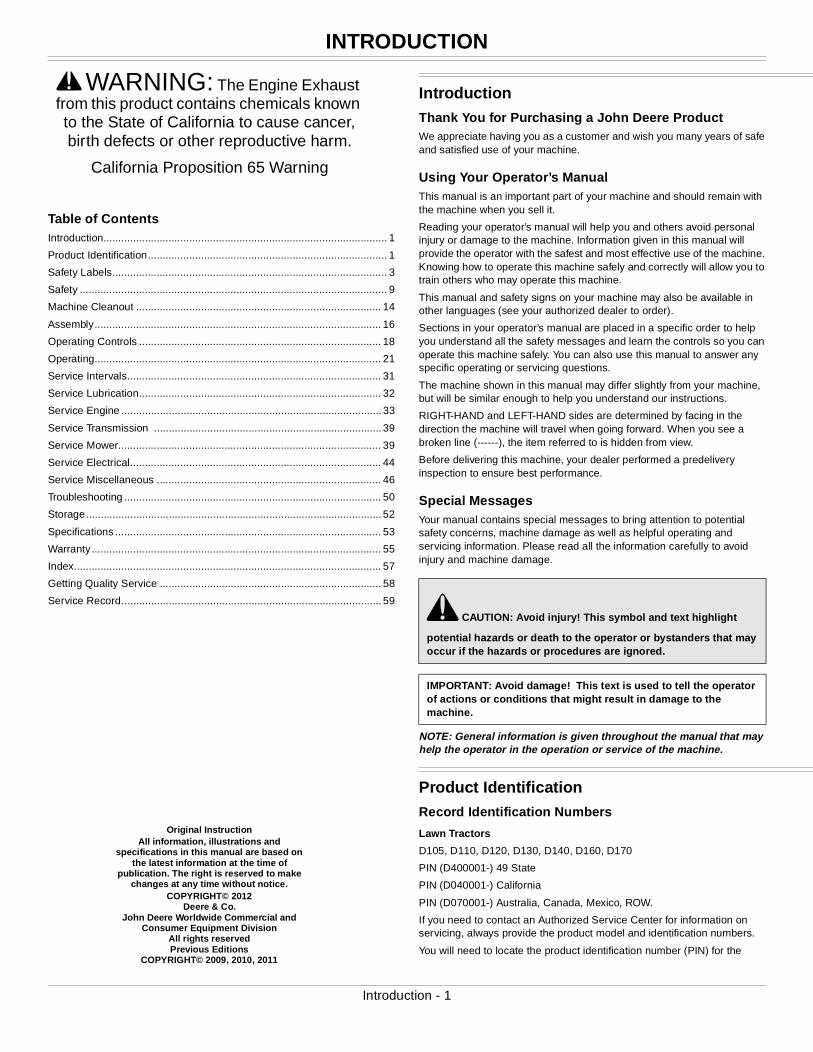
Machine Product Identification Number Location
MX46486
Picture Note: Located on left side of frame.
Engine Serial Number Location
MX25599
Picture Note: Single Cylinder Engines
MX49394
Picture Note: V-Twin Engines
Register Your Product and Warranty OnlineTo register your product through the Internet, simply go to www.JohnDeereWarrantyRegistration.com. Completing the information, either online or with the product warranty card, will ensure the customer that their product receives all post sales service and important product information.
Product Identification - 2
SAFETY LABELS
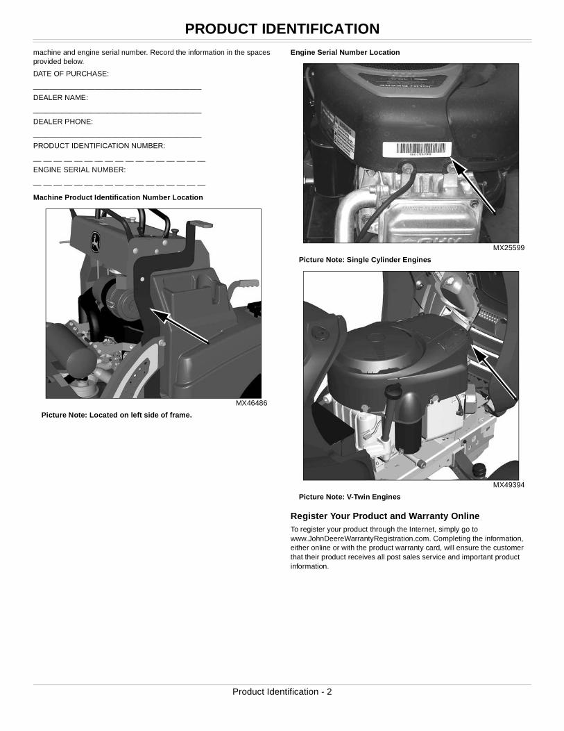
Safety LabelsSafety Label Location (Text)
MX46490
Picture Note: Use label number listed in table below to locate complete text of safety label message following this illustration.
A- WARNING GX22477
B- DANGER/CAUTION M128699
C- WARNING MX4878
D- DANGER M118610
E- CAUTION M165279
F- WARNING GX23479
G- DANGER GX22477
H- DANGER M89504
B
AC
D
H
GF
E
Safety Labels - 3
SAFETY LABELS
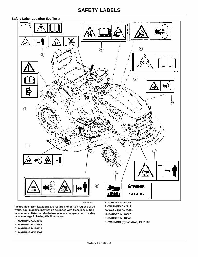
Safety Label Location (No Text)
MX46490
Picture Note: Non-text labels are required for certain regions of the world. Your machine may not be equipped with these labels. Use label number listed in table below to locate complete text of safety label message following this illustration.
A- WARNING GX24842
B- WARNING M128484
C- WARNING M136436
D- WARNING GX24503
E- DANGER M118041
F- WARNING GX21121
G- WARNING GX23479
H- DANGER M148522
I - DANGER M118040
J - WARNING (Bypass Rod) GX21086
J
A
E
I
H
F
G
B C
D
Safety Labels - 4
SAFETY LABELS
Understanding The Machine Safety LabelsThe machine safety labels shown in this section are placed in important areas on your machine to draw attention to potential safety hazards.
On your machine safety labels, the words DANGER, WARNING, and CAUTION are used with this safety-alert symbol. DANGER identifies the most serious hazards.
The operator’s manual also explains any potential safety hazards whenever necessary in special safety messages that are identified with the word, CAUTION, and the safety-alert symbol.
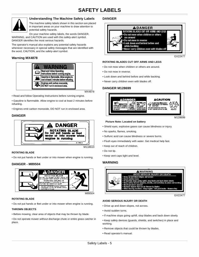
Warning MX4878
MX4878
• Read and follow Operating Instructions before running engine.
• Gasoline is flammable. Allow engine to cool at least 2 minutes before refueling.
• Engines emit carbon monoxide, DO NOT run in enclosed area.
DANGER
M118610
ROTATING BLADE
• Do not put hands or feet under or into mower when engine is running.
DANGER - M89504
M89504
ROTATING BLADE
• Do not put hands or feet under or into mower when engine is running.
THROWN OBJECTS
• Before mowing, clear area of objects that may be thrown by blade.
• Do not operate mower without discharge chute or entire grass catcher in place.
DANGER
GX22477
ROTATING BLADES CUT OFF ARMS AND LEGS
• Do not mow when children or others are around.
• Do not mow in reverse.
• Look down and behind before and while backing.
• Never carry children even with blades off.
DANGER M128699
M128699
Picture Note: Located on battery
• Shield eyes, explosive gases can cause blindness or injury.
• No sparks, flames, smoking.
• Sulfuric acid can cause blindness or severe burns.
• Flush eyes immediately with water. Get medical help fast.
• Keep out of reach of children.
• Do not tip.
• Keep vent caps tight and level.
WARNING
GX22477
AVOID SERIOUS INJURY OR DEATH
• Drive up and down slopes, not across.
• Avoid sudden turns.
• If machine stops going uphill, stop blades and back down slowly.
• Keep safety devices (guards, shields, and switches) in place and working.
• Remove objects that could be thrown by blades.
• Read operator’s manual.
Safety Labels - 5

SAFETY LABELS
• Remove objects that can be thrown by blades• When leaving machine:
–Stop engine
–Set park brake
–Remove key
DANGER GX23479
GX23479
WARNING
• Hot surface
Warning M159705
M159705
Picture Note: This label is required and installed on machines sold in California. This label may also be installed on machines sold in other locations.
Operation of This Equipment May Create Sparks that Can Start Fires Around Dry Vegetation. A Spark Arrestor May be Required. The Operator Should Contact Local Fire Agencies For Laws or Regulations Relating to Fire Prevention Requirements.
Prevent Equipment Fires
M165279
• Avoid equipment fires.
• Accumulation of grass, leaves and other debris on or near hot or moving parts can cause a fire.
• Inspect machine before, during, and after use.
• Shut off engine and allow machine to cool before cleaning.
Inspect and clean the entire machine and pay special attention to these locations:
1. Muffler and exhaust system
2. Engine and engine screens
3. Top of mower deck and under shields
4. On or near transmission
Emission Control System Certification Label
NOTE: Tampering with emission controls and components by unauthorized personnel may result in severe fines or penalties. Emission controls and components can only be adjusted by EPA and/or CARB authorized service centers. Contact your John Deere Retailer concerning emission controls and component questions.
The presence of an emissions label signifies that the engine has been certified with the United States Environmental Protection Agency (EPA) and/or California Air Resources Board (CARB).
The emissions warranty applies only to those engines marketed by John Deere that have been certified by the EPA and/or CARB; and used in the United States and Canada in off-road mobile equipment.
Safety Labels - 6
SAFETY LABELS
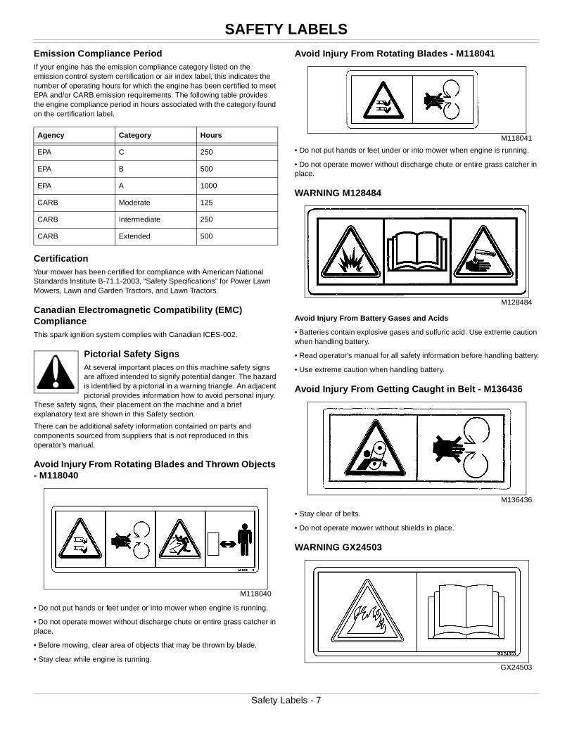
Emission Compliance PeriodIf your engine has the emission compliance category listed on the emission control system certification or air index label, this indicates the number of operating hours for which the engine has been certified to meet EPA and/or CARB emission requirements. The following table provides the engine compliance period in hours associated with the category found on the certification label.
CertificationYour mower has been certified for compliance with American National Standards Institute B-71.1-2003, “Safety Specifications” for Power Lawn Mowers, Lawn and Garden Tractors, and Lawn Tractors.
Canadian Electromagnetic Compatibility (EMC) ComplianceThis spark ignition system complies with Canadian ICES-002.
Pictorial Safety SignsAt several important places on this machine safety signs are affixed intended to signify potential danger. The hazard is identified by a pictorial in a warning triangle. An adjacent pictorial provides information how to avoid personal injury.
These safety signs, their placement on the machine and a brief explanatory text are shown in this Safety section.
There can be additional safety information contained on parts and components sourced from suppliers that is not reproduced in this operator’s manual.
Avoid Injury From Rotating Blades and Thrown Objects - M118040
M118040
• Do not put hands or feet under or into mower when engine is running.
• Do not operate mower without discharge chute or entire grass catcher in place.
• Before mowing, clear area of objects that may be thrown by blade.
• Stay clear while engine is running.
Avoid Injury From Rotating Blades - M118041
M118041
• Do not put hands or feet under or into mower when engine is running.
• Do not operate mower without discharge chute or entire grass catcher in place.
WARNING M128484
M128484
Avoid Injury From Battery Gases and Acids
• Batteries contain explosive gases and sulfuric acid. Use extreme caution when handling battery.
• Read operator’s manual for all safety information before handling battery.
• Use extreme caution when handling battery.
Avoid Injury From Getting Caught in Belt - M136436
M136436
• Stay clear of belts.
• Do not operate mower without shields in place.
WARNING GX24503
GX24503
Agency Category Hours
EPA C 250
EPA B 500
EPA A 1000
CARB Moderate 125
CARB Intermediate 250
CARB Extended 500
Safety Labels - 7
SAFETY LABELS
Clean and inspect the entire machine.Carefully read Operator’s Manual Machine Cleanout section for details.
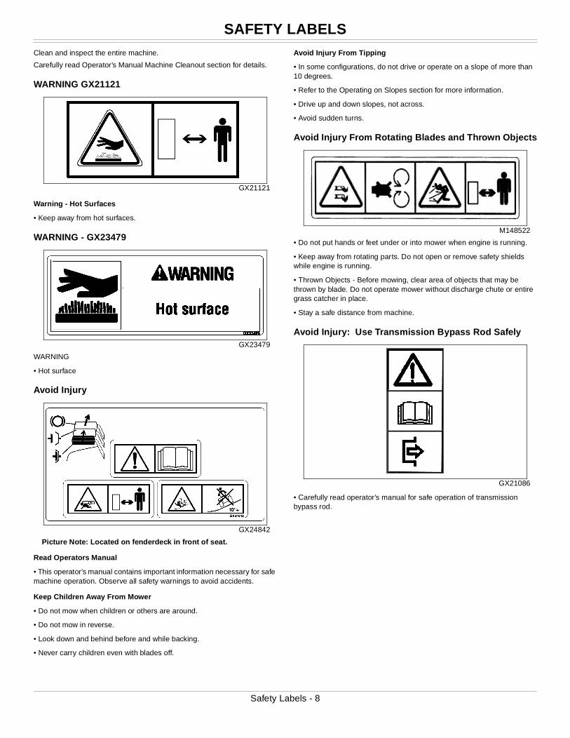
WARNING GX21121
GX21121
Warning - Hot Surfaces
• Keep away from hot surfaces.
WARNING - GX23479
GX23479
WARNING
• Hot surface
Avoid Injury
GX24842
Picture Note: Located on fenderdeck in front of seat.
Read Operators Manual
• This operator’s manual contains important information necessary for safe machine operation. Observe all safety warnings to avoid accidents.
Keep Children Away From Mower
• Do not mow when children or others are around.
• Do not mow in reverse.
• Look down and behind before and while backing.
• Never carry children even with blades off.
Avoid Injury From Tipping
• In some configurations, do not drive or operate on a slope of more than 10 degrees.
• Refer to the Operating on Slopes section for more information.
• Drive up and down slopes, not across.
• Avoid sudden turns.
Avoid Injury From Rotating Blades and Thrown Objects
M148522
• Do not put hands or feet under or into mower when engine is running.
• Keep away from rotating parts. Do not open or remove safety shields while engine is running.
• Thrown Objects - Before mowing, clear area of objects that may be thrown by blade. Do not operate mower without discharge chute or entire grass catcher in place.
• Stay a safe distance from machine.
Avoid Injury: Use Transmission Bypass Rod Safely
GX21086
• Carefully read operator’s manual for safe operation of transmission bypass rod.
Safety Labels - 8
SAFETY
SafetyOperating SafelyThis cutting machine is capable of amputating hands and feet and throwing objects. Failure to observe the following safety instructions could result in serious injury or death.
• Read, understand and follow all instructions on the machine and in manuals provided, and view safety video, before starting. Be thoroughly familiar with the controls and the proper use of the machine before starting.
• Do not put hands or feet near rotating parts or under the machine. Keep clear of the discharge opening at all times.
• Only allow responsible adults, who are familiar with the instructions, to operate this machine. Local regulations may restrict the age of the operator.
• Clear the area of objects such as rocks, wire and toys which could be thrown by the blades.
• Be sure the area is clear of bystanders before operating. Stop machine if anyone enters the area.
• Never carry passengers.
• Do not mow in reverse unless absolutely necessary. Always look down and behind before and while backing.
• Never direct discharged material toward anyone. Avoid discharging material against a wall or obstruction. Material may ricochet back toward the operator. Stop the blades when crossing gravel surfaces.
• Do not operate the machine without the entire grasscatcher, discharge guard, or other safety devices in place and working. Never operate with the discharge deflector raised, removed, or altered, unless using a grasscatcher.
• Slow down before turning.
• Never leave a running machine unattended. Always turn off blades, lock park brake, stop engine and remove key before dismounting.
• Disengage blades when not mowing. Shut off engine and wait for all parts to come to a complete stop before cleaning the machine, removing the grasscatcher, or unclogging the discharge chute.
• Operate machine only in daylight or good artificial light.
• Do not operate the machine while under the influence of alcohol or drugs.
• Watch for traffic when operating near or crossing roadways. Stop blades before crossing roads or sidewalks.
• Use extra care when loading or unloading the machine into a trailer or truck.
• Always wear safety goggles or safety glasses with side shields when operating machine.
• Data indicates operators 60 years and above are involved in a large percentage of riding mower-related injuries. These operators should evaluate their ability to operate the riding mower safely enough to protect themselves and others from serious injury.
• Follow the manufacturer’s recommendation for wheel weights or counterweights.
• Inspect machine before you operate. Be sure hardware is tight. Repair or replace damaged, badly worn, or missing parts. Be sure guards and shields are in good condition and fastened in place. Make any necessary adjustments before you operate.
• Before using, always visually inspect to see that the blades, blade bolts
and the mower assembly are not worn and damaged. Replace worn and damaged blades and bolts in sets to preserve balance.
• Make sure spark plug, muffler, fuel cap and air cleaner are in place before starting the engine.
• Be sure all drives are in neutral and parking brake is locked before starting engine. Only start engine from the operator’s position.
• Do not change the engine governor settings or overspeed the engine. Operating the engine at excessive speed can increase the hazard of personal injury.
• If you hit an object or if abnormal vibration occurs, stop the machine and inspect it. Make repairs before you operate.
• Use only accessories and attachments approved by the manufacturer of the machine. Keep safety labels visible when installing accessories and attachments.
• Do not wear radio or music headphones. Safe service and operation requires your full attention.
• When machine is left unattended, stored, or parked, lower the mower deck unless a positive mechanical lock is used.
Using a Spark ArrestorThe California Public Resources Code, section 4442.5 provides as follows:
No person shall sell, offer for sale, lease, or rent to any person any internal combustion engine subject to Section 4442 or 4443, and not subject to Section 13005 of the Health and Safety Code, unless the person provides a written notice to the purchaser or bailee, at the time of sale or at the time of entering into the lease or rental contract, stating that it is a violation of Section 4442 or 4443 to use or operate the engine on any forest-covered, brush-covered, or grass-covered land unless the engine is equipped with a spark arrestor, as defined in Section 4442, maintained in effective working order or the engine is constructed, equipped, and maintained for the prevention of fire pursuant to Section 4443. Cal. Pub. Res. Code 4442.5.
Other states or jurisdictions may have similar laws. A spark arrestor for your machine may be available from your authorized dealer. An installed spark arrestor must be maintained in good working order by the operator.
Checking Mowing Area
• Clear mowing area of objects that might be thrown. Keep people and pets out of mowing area.
• Low-hanging branches and similar obstacles can injure the operator or interfere with
mowing operation. Before mowing, identify potential obstacles such as low-hanging branches, and trim or remove those obstacles.
• Study mowing area. Set up a safe mowing pattern. Do not mow where traction or stability is doubtful.
• Test drive area with mower lowered but not running. Slow down when you travel over rough ground.
Parking Safely
1. Stop machine on a level surface, not on a slope.
2. Disengage mower blades or any other attachments.
3. Lower attachments to the ground.
4. Lock the park brake.
5. Stop the engine.
6. Remove the key.
Safety - 9
SAFETY
7. Wait for engine and all moving parts to stop before you leave the operator’s seat.8. Close fuel shut-off valve, if your machine is equipped.
9. Disconnect the negative battery cable or remove the spark plug wire(s) (for gasoline engines) before servicing the machine.
Rotating Blades are Dangerous
HELP PREVENT SERIOUS OR FATAL ACCIDENTS:
• Rotating blades can cut off arms and legs, and throw objects. Failure to observe safety instructions could result in serious injury or
death.
• Keep hands, feet and clothing away from mower deck when engine is running.
• Be alert at all times, drive forward and in reverse carefully. People, especially children can move quickly into the mowing area before you know it.
• Before backing up, stop mower blades or attachments and look down and behind the machine carefully, especially for children.
• Do not mow in reverse.
• Shut off blades when you are not mowing.
• Park machine safely before leaving the operator’s station for any reason including emptying the grasscatchers or unplugging the chute.
• The mower blades should stop in approximately five seconds when the mower is disengaged. If you believe that your blades may not be stopping in that period of time, take your machine to your authorized dealer where they can safely check and service your machine.
Protect Children
• Death or serious injury can occur when young children associate having fun with a lawn mowing machine simply because someone has given them a ride on a machine.
• Children are attracted to lawn mowing machines and mowing activities. They don’t understand the dangers of rotating blades or the fact that the operator is unaware of their presence.
• Children who have been given rides in the past may suddenly appear in the mowing area for another ride and be run over or backed over by the machine.
• Tragic accidents with children can occur if the operator is not alert to the presence of children, especially when a child approaches a machine from behind. Before and while backing up, stop mower blades and look down and behind the machine carefully, especially for children.
• Never carry children on a machine or attachment, even with the blades off. Do not tow children in a cart or trailer. They can fall off and be seriously injured or interfere with safe machine operation.
• Never use the machine as a recreational vehicle or to entertain children.
• Never allow children or an untrained person operate the machine. Instruct all operators not to give children a ride on the machine or in an attachment.
• Keep children indoors, out of the mowing area, and in the watchful eye of a responsible adult, other than the operator, when a mower is being operated.
• Stay alert to the presence of children. Never assume that children will
remain where you last saw them. Turn the machine off if a child enters the work area.
• Use extreme care when approaching blind corners, shrubs, trees, or other objects that may block your view of a child.
Operating on Slopes
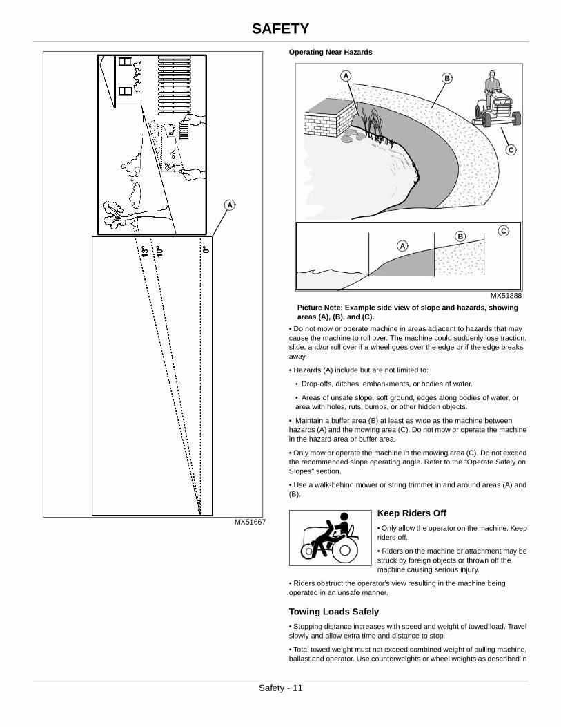
NOTE: Make a photocopy of this page and cut out angle chart (A) to use for measuring slope angle.
• Slopes are a major factor related to loss-of-control and tipover accidents, which can result in severe injury or death. Operation on all slopes requires extra caution.
Identify Slopes for Safe Operation
• Follow safe procedures for operation on slopes. Measure slopes of all moving sites to determine which slopes are safe for mowing with a ride-on mower. Always use common sense and good judgement when performing this survey.
Measuring Slopes
• Suggested Method 1: Lay a straight piece of sturdy lumber 1.2 m (4 ft) long on the slope and measure the angle of the slope with an angle indicator or protractor level.
• Suggested Method 2: Refer to the slope gauge provided with this manual.
Operate Safely on Slopes
• Exceeding the recommended maximum slope angle increases the risk of rollover accidents that can result in serious injury or death.
• Never mow or operate ride-on mower on slope angles greater than 13° with the lawn ride-on mower in its basic configuration. The basic configuration is the ride-on mower with mower deck and not other attachments. (A 13° slope is a slope that rises 1.4 m (4.6 ft) over a horizontal distance of 6.1 m (20 ft).)
• When using attachments, never mow or operate the ride-on mower on slope angles greater than 10°. The addition of a weather enclosure, material collection system, or other attachments will increase the risk of a rollover. (A 10° slope is a slope that rises 1 m (3.5 ft) over a horizontal distance of 6.1 m (20 ft).)
• On slope angles of 10° or less, the risk of rollover is low, but as the slope angle increases to the recommended maximum, the risk increases to a medium level.
• Always consider potential turf conditions and slope angles when determining the risk of loss-of-control and tip-over accidents.
• Drive slowly when mowing or operating on slopes.
• If you feel uneasy on a hillside, do not mow or operate on it.
• Mow up and down slopes, not across.
• Watch for holes, ruts, bumps, rocks, or other hidden objects. Uneven terrain could overturn the ride-on mower. Tall grass can hide obstacles.
• Drive slowly so you will not have to stop while on a slope.
• Do not mow on wet grass. Tires may lose traction. Tires may slip on slopes even though the brakes are functioning properly.
• Avoid starting, stopping or turning on a slope. If the tires lose traction, disengage the PTO and proceed slowly, straight down the slope.
• Keep all movement on slopes slow and gradual. Do not make sudden changes in speed or direction, which could cause the ride-on mower to roll over.
Safety - 10
SAFETY
MX51667
Operating Near Hazards
MX51888
Picture Note: Example side view of slope and hazards, showing areas (A), (B), and (C).
• Do not mow or operate machine in areas adjacent to hazards that may cause the machine to roll over. The machine could suddenly lose traction, slide, and/or roll over if a wheel goes over the edge or if the edge breaks away.
• Hazards (A) include but are not limited to:
• Drop-offs, ditches, embankments, or bodies of water.
• Areas of unsafe slope, soft ground, edges along bodies of water, or area with holes, ruts, bumps, or other hidden objects.
• Maintain a buffer area (B) at least as wide as the machine between hazards (A) and the mowing area (C). Do not mow or operate the machine in the hazard area or buffer area.
• Only mow or operate the machine in the mowing area (C). Do not exceed the recommended slope operating angle. Refer to the "Operate Safely on Slopes" section.
• Use a walk-behind mower or string trimmer in and around areas (A) and (B).
Keep Riders Off
• Only allow the operator on the machine. Keep riders off.
• Riders on the machine or attachment may be struck by foreign objects or thrown off the machine causing serious injury.
• Riders obstruct the operator’s view resulting in the machine being operated in an unsafe manner.
Towing Loads Safely
• Stopping distance increases with speed and weight of towed load. Travel slowly and allow extra time and distance to stop.
• Total towed weight must not exceed combined weight of pulling machine, ballast and operator. Use counterweights or wheel weights as described in
A
B
C
A
AB
C
Safety - 11
SAFETY
the attachment or pulling machine operator’s manual.• Excessive towed load can cause loss of traction and loss of control on slopes. Reduce towed weight when operating on slopes.
• Never allow children or others in or on towed equipment.
• Use only approved hitches. Tow only with a machine that has a hitch designed for towing. Do not attach towed equipment except at the approved hitch point.
• Follow the manufacturer’s recommendations for weight limits for towed equipment and towing on slopes.
• Towed attachments will increase the risk of rollover. Refer to the “Operating on Slopes” section for more information.
• Do not turn sharply. Use additional caution when turning or operating under adverse surface conditions. Use care when reversing.
• Do not shift to neutral and coast downhill.
Wear Appropriate Clothing
• Always wear eye protection when operating the machine.
• Wear close fitting clothing and safety equipment appropriate for the job.
• While operating this machine, always wear substantial footwear and long trousers. Do not operate the equipment when barefoot or wearing open sandals.
• Wear a suitable protective device such as earplugs. Loud noise can cause impairment or loss of hearing.
Driving Safely on Public RoadsAvoid personal injury or death resulting from a collision with another vehicle on public roads:
• Use safety lights and devices. Slow moving machines when driven on public roads are hard to see, especially at night.
• Whenever driving on public roads, use flashing warning lights and turn signals according to local regulations. Extra flashing warning lights may need to be installed.
Practice Safe Maintenance
• Only qualified, trained adults should service this machine. Understand service procedure before doing work.
• Never operate machine in a closed area where dangerous carbon monoxide fumes can collect.
• Keep all nuts and bolts tight, especially blade attachment bolts, to be sure the equipment is in safe working condition.
• Never tamper with safety devices. Check their proper operation regularly.
• Keep machine free of grass, leaves or other debris build-up. Clean up oil or fuel spillage and remove any fuel-soaked debris. Allow the machine to cool before storing.
• If you strike a foreign object, stop and inspect the machine. Repair, if necessary, before restarting.
• Never make any adjustments or repairs with the engine running. Wait for all movement to stop on machine before adjusting, cleaning or repairing.
• Check grasscatcher components and the discharge guard frequently and replace with manufacturer’s recommended parts, when necessary. Grasscatcher components are subject to wear, damage, and deterioration which could expose moving parts or allow objects to be thrown.
• Mower blades are sharp. Wrap the blade or wear gloves, and use extra care when servicing them. Only replace blades. Never straighten or weld them.
• Check brake operation frequently. Adjust and service as required.
• Maintain or replace safety and instruction labels, as necessary.
• On multi-bladed machines, take care as rotating one blade can cause other blades to rotate.
• Keep hands, feet, clothing, jewelry, and long hair away from any moving parts, to prevent them from getting caught.
• Lower any attachments to the ground before cleaning or servicing machine. Disengage all power and stop the engine. Lock park brake and remove the key. Let machine cool.
• Securely support any machine elements that must be raised for service work. Use jack stands or lock service latches to support components when needed.
• Disconnect battery or remove spark plug wire (for gasoline engines) before making any repairs. Disconnect negative terminal first and positive last. Install positive terminal first and negative last.
• Before servicing machine or attachment, carefully release pressure from any components with stored energy, such as hydraulic components or springs.
• Keep all parts in good condition and properly installed. Fix damage immediately. Replace worn or broken parts.
• Charge batteries in an open, well-ventilated area, away from sparks. Unplug battery charger before connecting or disconnecting from the battery. Wear protective clothing and use insulated tools.
• Do not strike the flywheel with a hammer or hard object because the flywheel may later shatter during operation.
• If equipped with hydraulic lift - release hydraulic pressure by lowering attachment or cutting units to the ground or to a mechanical stop and move hydraulic control levers back and forth.
Avoid High Pressure Fluids
• Hydraulic hoses and lines can fail due to physical damage, kinks, age, and exposure. Check hoses and lines regularly. Replace damaged hoses and lines.
• Hydraulic fluid connections can loosen due to physical damage and vibration. Check connections regularly. Tighten loose connections.
• Escaping fluid under pressure can penetrate the skin causing serious injury. Avoid the hazard by relieving pressure before disconnecting hydraulic or other lines. Tighten all connections before applying pressure.
• Search for leaks with a piece of cardboard. Protect hands and body from high pressure fluids.
• If an accident occurs, see a doctor immediately. Any fluid injected into the skin must be surgically removed within a few hours or gangrene may result. Doctors unfamiliar with this type of injury should reference a knowledgeable medical source. Such information is available from Deere & Company Medical Department in Moline, Illinois, U.S.A. Information may be obtained in the United States and Canada only by calling 1-800-822-8262.
Safety - 12
SAFETY
Prevent Fires
• Besides routine maintenance, one of the best ways to keep your John Deere equipment running efficiently and to reduce fire risk is to regularly remove debris buildup from the machine.
• Please review these recommendations with all operators. See your John Deere dealer with
questions.
• Always follow all safety procedures posted on the machine and in this operator manual. Before carrying out any inspection or cleaning, always shut off engine, set parking brake and remove ignition key.
• After operating, allow machine to cool in an open area before cleaning or storing. Do not park machine near flammable materials such as wood, cloth or chemicals.
• Empty any grasscatcher bags or containers completely before storing.
• Frequency of these inspections and cleaning will vary depending on a number of factors including operating conditions, machine configuration, operating speeds and weather conditions particularly dry, hot and windy conditions. When you are operating in these conditions, inspect and clean these areas frequently throughout the day.
• Wind direction, terrain type and moisture content of surrounding vegetation can effect where and how much debris accumulates.
• Debris can accumulate anywhere on the machine, especially on horizontal surfaces.
• Keeping engine area clean will provide the greatest impact on fire prevention. Other areas requiring regular inspection and cleaning include behind wheel rims, wire harness, hose/line routings, mowing attachments, etc. Compressed air, leaf blowers or high pressured water can assist keeping these areas clean.
• Excess lubrication or fuel/oil leaks or spills on the machine can also serve as collection sites for debris. Prompt machine repair and oil/fuel cleanup will minimize the potential for debris collection and reduced cooling throughout machine life.
• Bearing failures or overheating can result in a fire. To reduce this risk, always follow the instructions in the machine operator’s manual regarding lubrication intervals and locations. Washing the machine while warm may also reduce bearing life and increase potential for premature bearing failure.
• Always shut off fuel when storing or transporting machine, if the machine has a fuel shutoff.
Handling Fuel Safely
To avoid personal injury or property damage, use extreme care in handling fuel. Fuel is extremely flammable and fuel vapors are explosive:
• Extinguish all cigarettes, cigars, pipes, and other sources of ignition.
• Use only an approved fuel container. Use only non-metal, portable fuel containers approved by the Underwriter’s Laboratory (U.L.) or the American Society for Testing & Materials (ASTM). If using a funnel, make sure it is plastic and has no screen or filter.
• Never remove the fuel tank cap or add fuel with the engine running. Allow engine to cool before refueling.
• Never add fuel to or drain fuel from the machine indoors. Move machine
outdoors and provide adequate ventilation.
• Clean up spilled fuel immediately. If fuel is spilled on clothing, change clothing immediately. If fuel is spilled near machine, do not attempt to start the engine but move the machine away from the area of spillage. Avoid creating any source of ignition until fuel vapors have dissipated.
• Never store the machine or fuel container where there is an open flame, spark, or pilot light such as on a water heater or other appliance.
• Prevent fire and explosion caused by static electric discharge. Static electric discharge can ignite fuel vapors in an ungrounded fuel container.
• Never fill containers inside a vehicle or on a truck or trailer bed with a plastic liner. Always place containers on the ground away from your vehicle before fueling.
• Remove fuel-powered equipment from the truck or trailer and refuel it on the ground. If this is not possible, then refuel such equipment with a portable container, rather than from a fuel dispenser nozzle.
• Keep the nozzle in contact with the rim of the fuel tank or container opening at all times until the fueling is complete. Do not use a nozzle lock-open device.
• Never overfill fuel tank. Replace fuel tank cap and tighten securely.
• Replace all fuel container caps securely after use.
• For gasoline engines, do not use gas with methanol. Methanol is harmful to your health and to the environment.
Tire SafetyExplosive separation of a tire and rim parts can cause serious injury or death:
• Do not attempt to mount a tire without the proper equipment and experience to perform the job.
• Always maintain the correct tire pressure. Do not inflate the tires above the recommended pressure. Never weld or heat a wheel and tire assembly. The heat can cause an increase in air pressure resulting in a tire explosion. Welding can structurally weaken or deform the wheel.
• When inflating tires, use a clip-on chuck and extension hose long enough to allow you to stand to one side and NOT in front of or over the tire assembly.
• Check tires for low pressure, cuts, bubbles, damaged rims or missing lug bolts and nuts.
Checking Wheel Hardware
• A serious accident could occur causing serious injury if wheel hardware is not tight.
• Check wheel hardware tightness often during the first 100 hours of operation.
• Wheel hardware must be tightened to specified torque using the proper procedure anytime it is loosened.
Handling Waste Product and Chemicals Waste products, such as, used oil, fuel, coolant, brake fluid, and batteries, can harm the environment and people:
• Do not use beverage containers for waste fluids - someone may drink from them.
• See your local Recycling Center or authorized dealer to learn how to recycle or get rid of waste products.
• A Material Safety Data Sheet (MSDS) provides specific details on chemical products: physical and health hazards, safety procedures, and
Safety - 13
MACHINE CLEANOUT
emergency response techniques. The seller of the chemical products used with your machine is responsible for providing the MSDS for that product.Machine CleanoutPrevent Fires
• Besides routine maintenance, one of the best ways to keep your John Deere equipment running efficiently and to reduce fire risk is to regularly remove debris buildup from the machine.
• Please review these recommendations with all operators. See your John Deere dealer with questions.
• Always follow all safety procedures posted on the machine and in this operator manual. Before carrying out any inspection or cleaning, always shut off engine, set parking brake and remove ignition key.
• After operating, allow machine to cool in an open area before cleaning or storing. Do not park machine near flammable materials such as wood, cloth or chemicals.
• Empty any grasscatcher bags or containers completely before storing.
• Frequency of these inspections and cleaning will vary depending on a number of factors including operating conditions, machine configuration, operating speeds and weather conditions particularly dry, hot and windy conditions. When you are operating in these conditions, inspect and clean these areas frequently throughout the day.
• Wind direction, terrain type and moisture content of surrounding vegetation can effect where and how much debris accumulates.
• Debris can accumulate anywhere on the machine, especially on horizontal surfaces.
• Keeping engine area clean will provide the greatest impact on fire prevention. Other areas requiring regular inspection and cleaning include behind wheel rims, wire harness, hose/line routings, mowing attachments, etc. Compressed air, leaf blowers or high pressured water can assist keeping these areas clean.
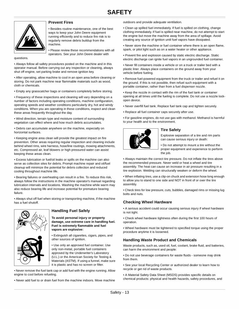
• Primary areas that must be inspected and cleaned on the machine include (See Safety Label Section):
MX48341
Picture Note: Single cylinder shown.
MX48340
Picture Note: Twin cylinder shown.
a.Exhaust manifold (A), muffler pipe (B), muffler (C) and muffler shield (D).
A
B
D C
B
B
DC
A
A
Machine Cleanout - 14
MACHINE CLEANOUT
MX49847
Picture Note: Single cylinder shown.
MX49848
Picture Note: Twin cylinder shown.
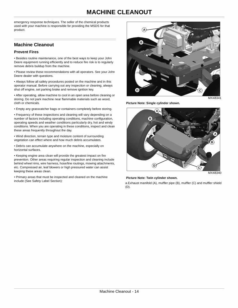
b.Engine intake screens (E), cooling fins (F), and oil cooler (if equipped).
MX49849
c.Top of mower deck, under shields (G), including spindle (H) and belt areas.
MX38694
Picture Note: Shown with wheel removed.
d.On or near transmission (I) and driveline (J).
E
F
E
F
G
H
IJ
Machine Cleanout - 15
ASSEMBLY
MX49850
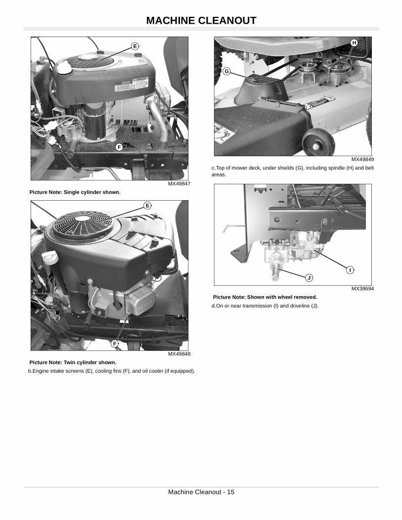
e.Under left side panel near fuse block (K), and all wiring, including the battery (L) and related wiring harnesses (M).
• Excess lubrication or fuel/oil leaks or spills on the machine can also serve as collection sites for debris. Prompt machine repair and oil/fuel cleanup will minimize the potential for debris collection and reduced cooling throughout machine life.
• Bearing failures or overheating can result in a fire. To reduce this risk, always follow the instructions in the machine operator’s manual regarding lubrication intervals and locations. Washing the machine while warm may also reduce bearing life and increase potential for premature bearing failure.
• Always shut off fuel when storing or transporting machine, if the machine has a fuel shutoff.
AssemblyCharge and Connect Battery
1. Remove and discard the tie strap from the positive (+) battery terminal.
2. Remove and discard the black protective cap from the negative (–)
battery terminal.
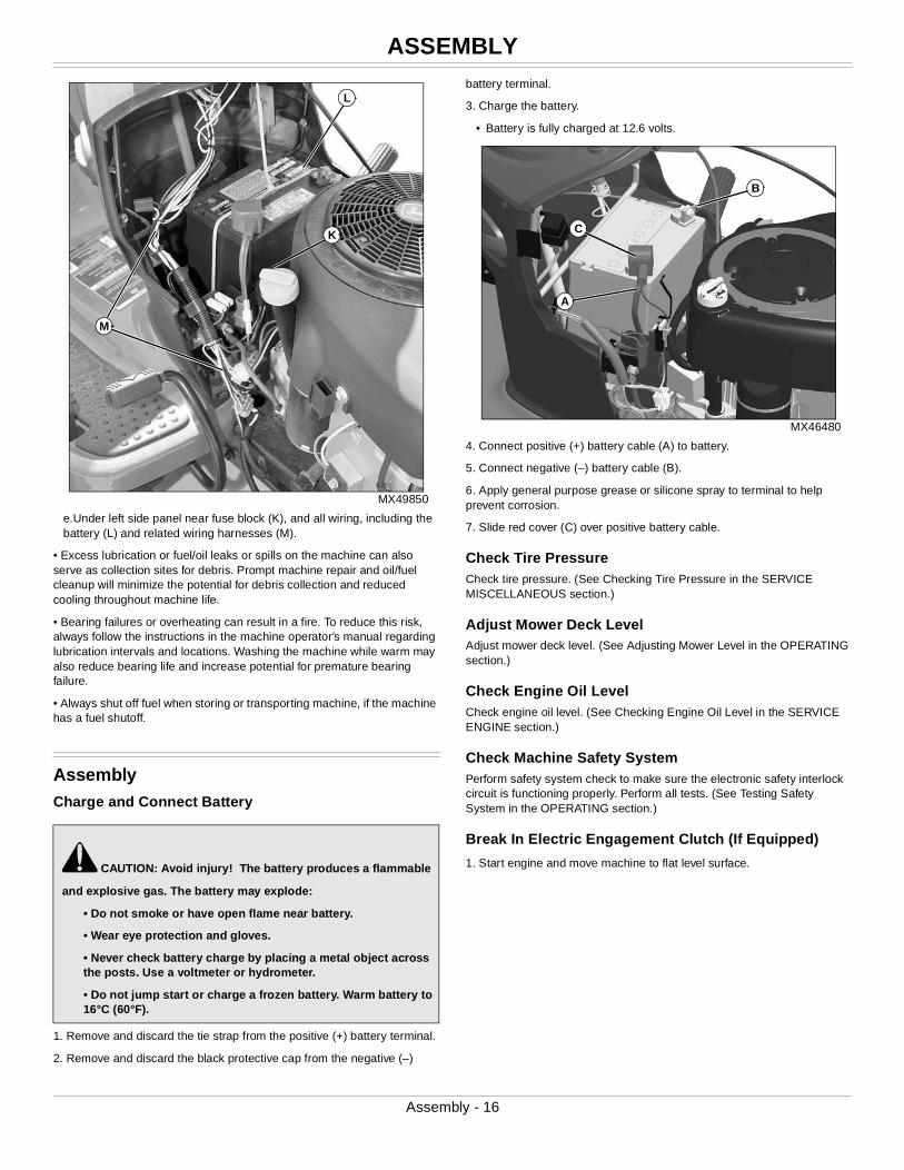
3. Charge the battery.
• Battery is fully charged at 12.6 volts.
MX46480
4. Connect positive (+) battery cable (A) to battery.
5. Connect negative (–) battery cable (B).
6. Apply general purpose grease or silicone spray to terminal to help prevent corrosion.
7. Slide red cover (C) over positive battery cable.
Check Tire PressureCheck tire pressure. (See Checking Tire Pressure in the SERVICE MISCELLANEOUS section.)
Adjust Mower Deck LevelAdjust mower deck level. (See Adjusting Mower Level in the OPERATING section.)
Check Engine Oil LevelCheck engine oil level. (See Checking Engine Oil Level in the SERVICE ENGINE section.)
Check Machine Safety SystemPerform safety system check to make sure the electronic safety interlock circuit is functioning properly. Perform all tests. (See Testing Safety System in the OPERATING section.)
Break In Electric Engagement Clutch (If Equipped)
1. Start engine and move machine to flat level surface.c CAUTION: Avoid injury! The battery produces a flammable
and explosive gas. The battery may explode:
• Do not smoke or have open flame near battery.
• Wear eye protection and gloves.
• Never check battery charge by placing a metal object across the posts. Use a voltmeter or hydrometer.
• Do not jump start or charge a frozen battery. Warm battery to 16°C (60°F).
K
L
M
A
B
C
Assembly - 16
ASSEMBLY
MX49386
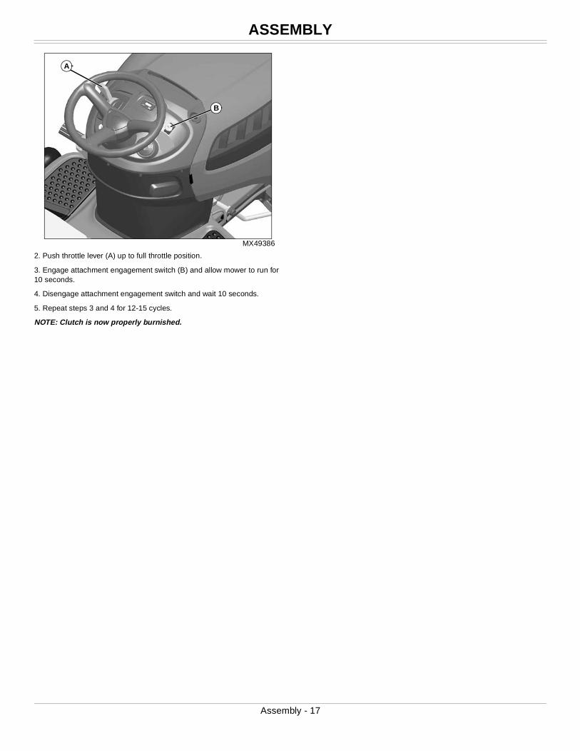
2. Push throttle lever (A) up to full throttle position.
3. Engage attachment engagement switch (B) and allow mower to run for 10 seconds.
4. Disengage attachment engagement switch and wait 10 seconds.
5. Repeat steps 3 and 4 for 12-15 cycles.
NOTE: Clutch is now properly burnished.
A
B
Assembly - 17
OPERATING CONTROLS
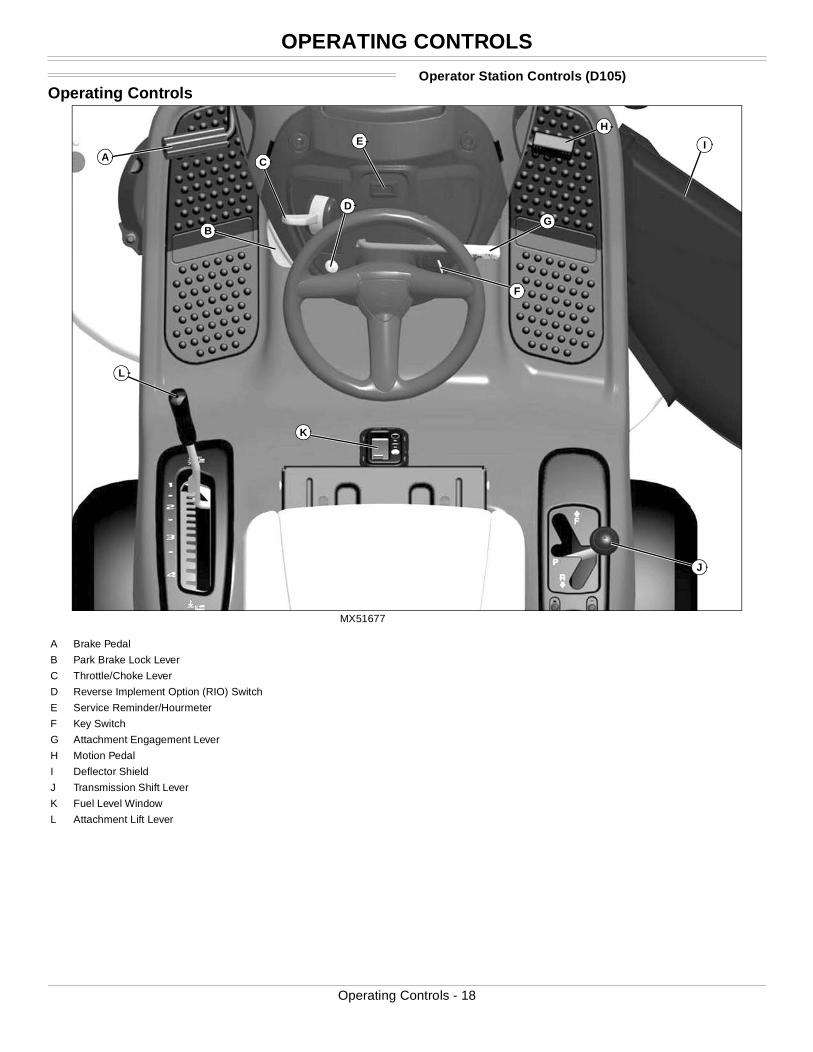
Operating ControlsOperator Station Controls (D105)
MX51677
A
G
F
K
C
D
B
L
J
IEH
A Brake Pedal
B Park Brake Lock Lever
C Throttle/Choke Lever
D Reverse Implement Option (RIO) Switch
E Service Reminder/Hourmeter
F Key Switch
G Attachment Engagement Lever
H Motion Pedal
I Deflector Shield
J Transmission Shift Lever
K Fuel Level Window
L Attachment Lift Lever
Operating Controls - 18
OPERATING CONTROLS
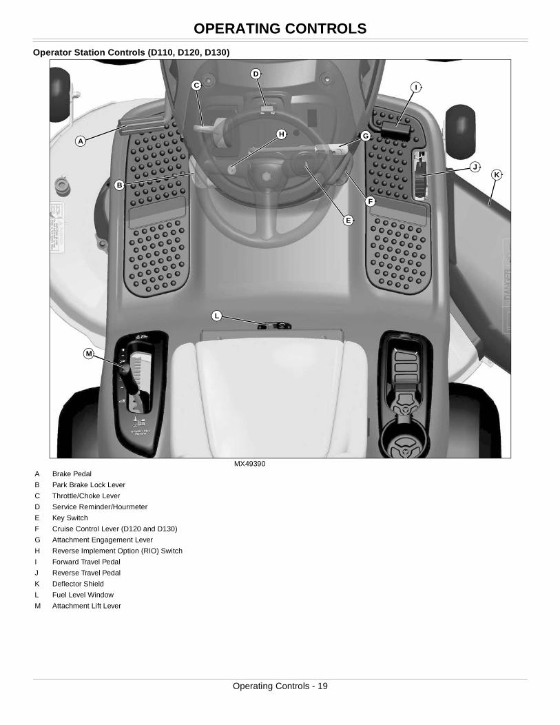
Operator Station Controls (D110, D120, D130)
MX49390
AG
L
C
H
B
M
K
I
J
D
E
F
A Brake Pedal
B Park Brake Lock Lever
C Throttle/Choke Lever
D Service Reminder/Hourmeter
E Key Switch
F Cruise Control Lever (D120 and D130)
G Attachment Engagement Lever
H Reverse Implement Option (RIO) Switch
I Forward Travel Pedal
J Reverse Travel Pedal
K Deflector Shield
L Fuel Level Window
M Attachment Lift Lever
Operating Controls - 19
OPERATING CONTROLS
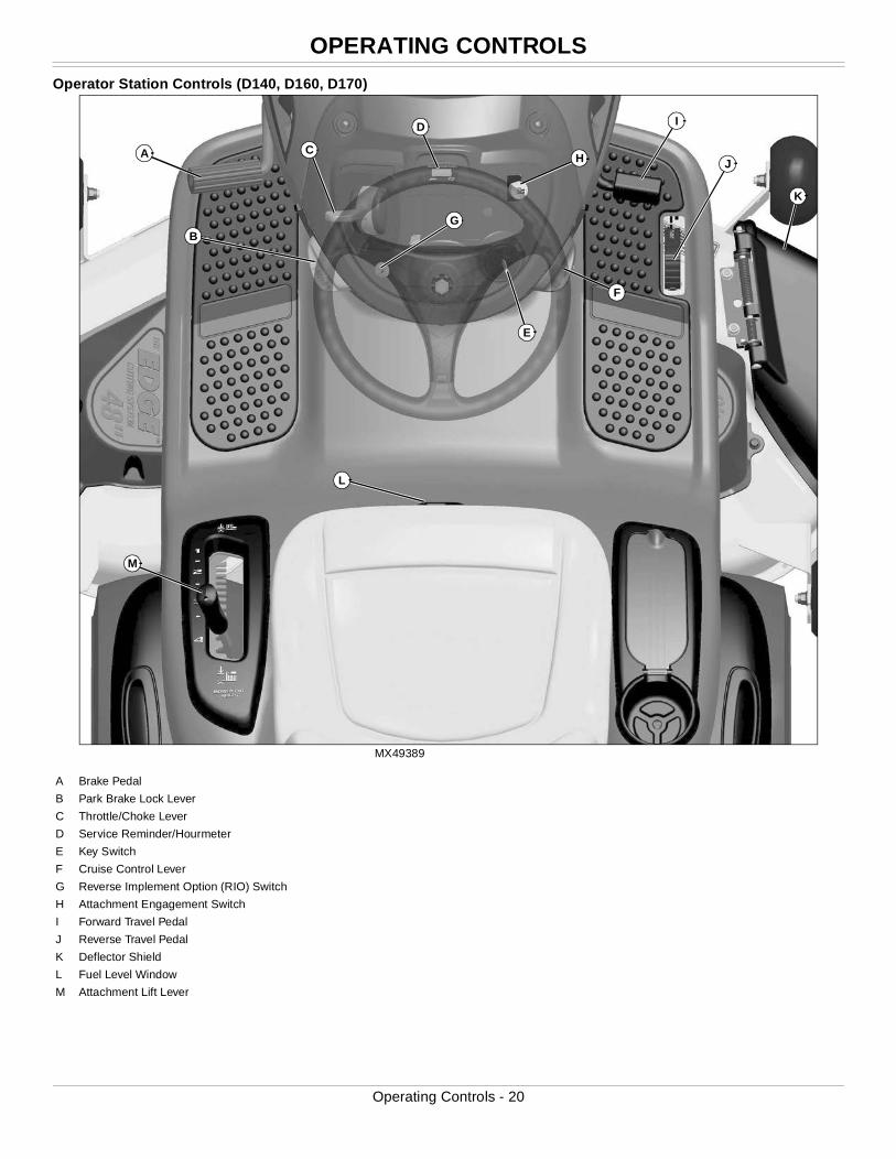
Operator Station Controls (D140, D160, D170)
MX49389
A H
E
L
B
M
K
D
F
G
I
CJ
A Brake Pedal
B Park Brake Lock Lever
C Throttle/Choke Lever
D Service Reminder/Hourmeter
E Key Switch
F Cruise Control Lever
G Reverse Implement Option (RIO) Switch
H Attachment Engagement Switch
I Forward Travel Pedal
J Reverse Travel Pedal
K Deflector Shield
L Fuel Level Window
M Attachment Lift Lever
Operating Controls - 20

OPERATING
OperatingDaily Operating Checklist
❏ Test safety systems.
❏ Check tire pressure.
❏ Check fuel level. (See SERVICE MISCELLANEOUS section, Using
Proper Fuel and Stabilizer)
❏ Check engine oil level.
❏ Remove grass and debris from engine compartment and muffler
area, and on top of mower deck, before and after operating machine.
❏ Clean air intake screen.
❏ Check area below machine for leaks.
Avoid Damage to Plastic and Painted Surfaces
• Do not wipe plastic parts unless rinsed first. Using a dry cloth may cause scratches.
• Insect repellent spray may damage plastic and painted surfaces. Do not spray insect repellent near machine.
• Be careful not to spill fuel on machine. Fuel may damage surface. Wipe up spilled fuel immediately.
• Prolonged exposure to sunlight will damage hood surfaces.
Adjusting Seat
1. Sit in seat.
MX46483
2. Lift up on seat adjustment lever (A) on right side of seat.
3. Lean forward and slide seat forward or rearward to desired position. Do not lean back on top of seat to push rearward.
4. Release seat adjustment lever to lock in position.
Lumbar Seat Adjustment (D160, D170)
• Turn lumbar seat adjustment dials (B) on either side of seat to adjust firmness of seat.
Adjusting Cutting HeightCutting height can be adjusted from approximately 25 - 100 mm (1 - 4 in.) in 6.4 mm (1/4 in.) increments. When mower deck is in transport position, cutting height is approximately 100 mm (4 in.).
Detents allow the adjustment lever to be positioned at each indicated mower setting, as well as the mid-point between each setting.
1. Put attachment lift lever into the slot adjacent to desired cutting height.
2. Adjust mower deck wheels.
Transporting or Getting On and Off Machine
• Pull attachment lift lever all the way back to transport position or 100 mm (4 in.) cutting height.
Checking and Adjusting Mower Deck Level
NOTE: Mower deck wheels should not contact the ground when leveling the mower deck.
Method One
1. Make sure machine is on a flat, level surface.
2. Park machine safely. (See Parking Safely in the SAFETY section.)
3. Check that tires are inflated to correct tire pressure. Tire pressure is marked on the side of the tire.
IMPORTANT: Avoid damage! Using stale, contaminated or improper fuel can result in engine and fuel system damage. Repairs caused by stale, contaminated or improper fuel are not covered by warranty.
A
B
Mower Setting Approximate Cutting Height
1 25 mm (1 in.)
– 38 mm (1 1/2 in.)
2 50 mm (2 in.)
– 65 mm (2 1/2 in.)
3 75 mm (3 in.)
– 90 mm (3 1/2 in.)
4 (Transport) 100 mm (4 in.)
c CAUTION: Avoid injury! Rotating blades are dangerous.
Before adjusting or servicing mower:
• Disconnect spark plug wire(s) or battery negative (-) cable to prevent engine from starting accidently.
• Always wear gloves when handling mower blades or working near blades.
Operating - 21
OPERATING
M17687a
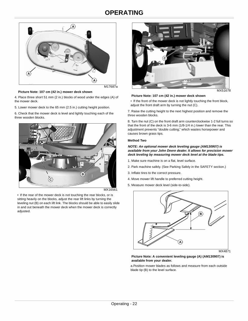
Picture Note: 107 cm (42 in.) mower deck shown
4. Place three short 51 mm (2 in.) blocks of wood under the edges (A) of the mower deck.
5. Lower mower deck to the 65 mm (2.5 in.) cutting height position.
6. Check that the mower deck is level and lightly touching each of the three wooden blocks.
MX16561
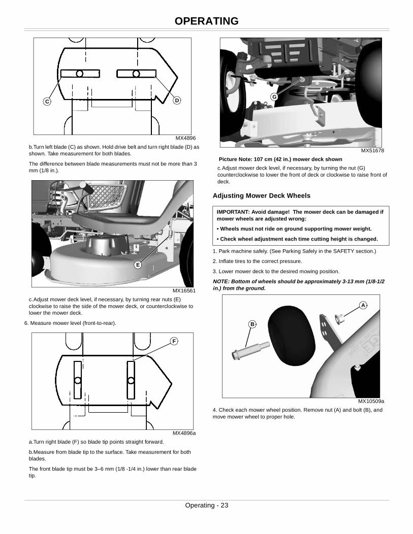
• If the rear of the mower deck is not touching the rear blocks, or is sitting heavily on the blocks, adjust the rear lift links by turning the leveling nut (B) on each lift link. The blocks should be able to easily slide in and out beneath the mower deck when the mower deck is correctly adjusted.
MX51678
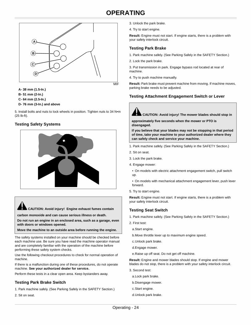
Picture Note: 107 cm (42 in.) mower deck shown
• If the front of the mower deck is not lightly touching the front block, adjust the front draft arm by turning the nut (C).
7. Raise the cutting height to the next highest position and remove the three wooden blocks.
8. Turn the nut (C) on the front draft arm counterclockwise 1-2 full turns so that the front of the deck is 3-6 mm (1/8-1/4 in.) lower than the rear. This adjustment prevents “double cutting,” which wastes horsepower and causes brown grass tips.
Method Two
NOTE: An optional mower deck leveling gauge (AM130907) is available from your John Deere dealer. It allows for precision mower deck leveling by measuring mower deck level at the blade tips.
1. Make sure machine is on a flat, level surface.
2. Park machine safely. (See Parking Safely in the SAFETY section.)
3. Inflate tires to the correct pressure.
4. Move mower lift handle to preferred cutting height.
5. Measure mower deck level (side-to-side).
MX4871
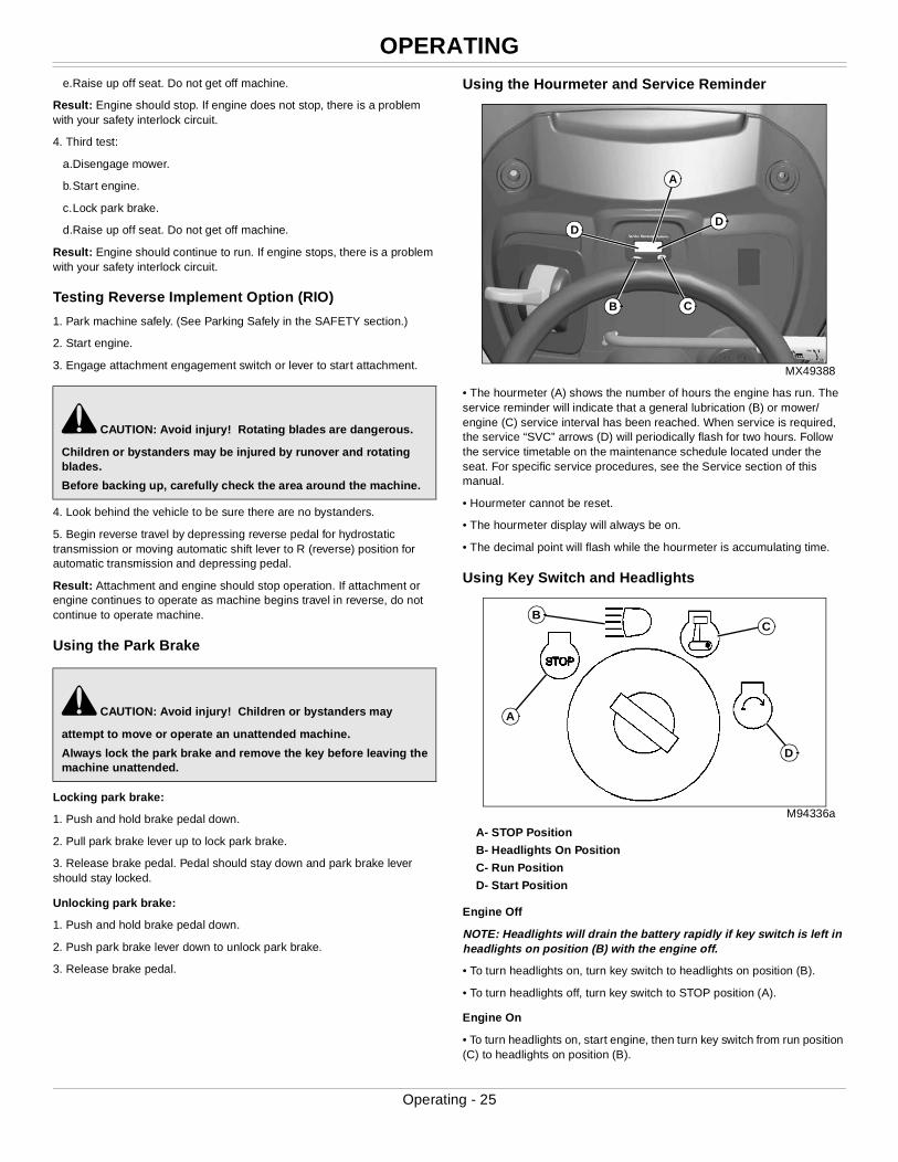
Picture Note: A convenient leveling gauge (A) (AM130907) is available from your dealer.
a.Position mower blades as follows and measure from each outside blade tip (B) to the level surface.
A
A
A
B
C
C
A
B
Operating - 22
OPERATING
MX4896
b.Turn left blade (C) as shown. Hold drive belt and turn right blade (D) as shown. Take measurement for both blades.
The difference between blade measurements must not be more than 3 mm (1/8 in.).
MX16561
c.Adjust mower deck level, if necessary, by turning rear nuts (E) clockwise to raise the side of the mower deck, or counterclockwise to lower the mower deck.
6. Measure mower level (front-to-rear).
MX4896a
a.Turn right blade (F) so blade tip points straight forward.
b.Measure from blade tip to the surface. Take measurement for both blades.
The front blade tip must be 3–6 mm (1/8 -1/4 in.) lower than rear blade tip.
MX51678
Picture Note: 107 cm (42 in.) mower deck shown
c.Adjust mower deck level, if necessary, by turning the nut (G) counterclockwise to lower the front of deck or clockwise to raise front of deck.
Adjusting Mower Deck Wheels
1. Park machine safely. (See Parking Safely in the SAFETY section.)
2. Inflate tires to the correct pressure.
3. Lower mower deck to the desired mowing position.
NOTE: Bottom of wheels should be approximately 3-13 mm (1/8-1/2 in.) from the ground.
MX10509a
4. Check each mower wheel position. Remove nut (A) and bolt (B), and move mower wheel to proper hole.
DC
E
F
IMPORTANT: Avoid damage! The mower deck can be damaged if mower wheels are adjusted wrong:
• Wheels must not ride on ground supporting mower weight.
• Check wheel adjustment each time cutting height is changed.
G
A
B
Operating - 23
OPERATING
MIF
A- 38 mm (1.5-In.)
B- 51 mm (2-In.)
C- 64 mm (2.5-In.)
D- 76 mm (3-In.) and above
5. Install bolts and nuts to lock wheels in position. Tighten nuts to 34 N•m (25 lb-ft).
Testing Safety Systems
The safety systems installed on your machine should be checked before each machine use. Be sure you have read the machine operator manual and are completely familiar with the operation of the machine before performing these safety system checks.
Use the following checkout procedures to check for normal operation of machine.
If there is a malfunction during one of these procedures, do not operate machine. See your authorized dealer for service.
Perform these tests in a clear open area. Keep bystanders away.
Testing Park Brake Switch
1. Park machine safely. (See Parking Safely in the SAFETY Section.)
2. Sit on seat.
3. Unlock the park brake.
4. Try to start engine.
Result: Engine must not start. If engine starts, there is a problem with your safety interlock circuit.
Testing Park Brake
1. Park machine safely. (See Parking Safely in the SAFETY Section.)
2. Lock the park brake.
3. Put transmission in park. Engage bypass rod located at rear of machine.
4. Try to push machine manually.
Result: Park brake must prevent machine from moving. If machine moves, parking brake needs to be adjusted.
Testing Attachment Engagement Switch or Lever
1. Park machine safely. (See Parking Safely in the SAFETY Section.)
2. Sit on seat.
3. Lock the park brake.
4. Engage mower:
• On models with electric attachment engagement switch, pull switch up.
• On models with mechanical attachment engagement lever, push lever forward.
5. Try to start engine.
Result: Engine must not start. If engine starts, there is a problem with your safety interlock circuit.
Testing Seat Switch
1. Park machine safely. (See Parking Safely in the SAFETY Section.)
2. First test:
a.Start engine.
b.Move throttle lever up to maximum engine speed.
c.Unlock park brake.
d.Engage mower.
e.Raise up off seat. Do not get off machine.
Result: Engine and mower blades should stop. If engine and mower blades do not stop, there is a problem with your safety interlock circuit.
3. Second test:
a.Lock park brake.
b.Disengage mower.
c.Start engine.
d.Unlock park brake.
c CAUTION: Avoid injury! Engine exhaust fumes contain
carbon monoxide and can cause serious illness or death.
Do not run an engine in an enclosed area, such as a garage, even with doors or windows opened.
Move the machine to an outside area before running the engine.
D
C
B
A
c CAUTION: Avoid injury! The mower blades should stop in
approximately five seconds when the mower or PTO is disengaged.
If you believe that your blades may not be stopping in that period of time, take your machine to your authorized dealer where they can safely check and service your machine.
Operating - 24
OPERATING
e.Raise up off seat. Do not get off machine.Result: Engine should stop. If engine does not stop, there is a problem with your safety interlock circuit.
4. Third test:
a.Disengage mower.
b.Start engine.
c.Lock park brake.
d.Raise up off seat. Do not get off machine.
Result: Engine should continue to run. If engine stops, there is a problem with your safety interlock circuit.
Testing Reverse Implement Option (RIO)
1. Park machine safely. (See Parking Safely in the SAFETY section.)
2. Start engine.
3. Engage attachment engagement switch or lever to start attachment.
4. Look behind the vehicle to be sure there are no bystanders.
5. Begin reverse travel by depressing reverse pedal for hydrostatic transmission or moving automatic shift lever to R (reverse) position for automatic transmission and depressing pedal.
Result: Attachment and engine should stop operation. If attachment or engine continues to operate as machine begins travel in reverse, do not continue to operate machine.
Using the Park Brake
Locking park brake:
1. Push and hold brake pedal down.
2. Pull park brake lever up to lock park brake.
3. Release brake pedal. Pedal should stay down and park brake lever should stay locked.
Unlocking park brake:
1. Push and hold brake pedal down.
2. Push park brake lever down to unlock park brake.
3. Release brake pedal.
Using the Hourmeter and Service Reminder
MX49388
• The hourmeter (A) shows the number of hours the engine has run. The service reminder will indicate that a general lubrication (B) or mower/engine (C) service interval has been reached. When service is required, the service “SVC” arrows (D) will periodically flash for two hours. Follow the service timetable on the maintenance schedule located under the seat. For specific service procedures, see the Service section of this manual.
• Hourmeter cannot be reset.
• The hourmeter display will always be on.
• The decimal point will flash while the hourmeter is accumulating time.
Using Key Switch and Headlights
M94336a
A- STOP Position
B- Headlights On Position
C- Run Position
D- Start Position
Engine Off
NOTE: Headlights will drain the battery rapidly if key switch is left in headlights on position (B) with the engine off.
• To turn headlights on, turn key switch to headlights on position (B).
• To turn headlights off, turn key switch to STOP position (A).
Engine On
• To turn headlights on, start engine, then turn key switch from run position (C) to headlights on position (B).
c CAUTION: Avoid injury! Rotating blades are dangerous.
Children or bystanders may be injured by runover and rotating blades.
Before backing up, carefully check the area around the machine.
c CAUTION: Avoid injury! Children or bystanders may
attempt to move or operate an unattended machine.
Always lock the park brake and remove the key before leaving the machine unattended.
A
B C
DD
A
BC
D
Operating - 25
OPERATING
• To turn headlights off, turn key switch from headlights on position (B) to run position (C).Starting the Engine
1. Make sure bypass rod is pushed in.
2. Sit in seat.
3. Make sure mower is disengaged. (See Engaging and Disengaging Mower in the OPERATING section.)
4. Lock the park brake.
5. For automatic models, put transmission in park.
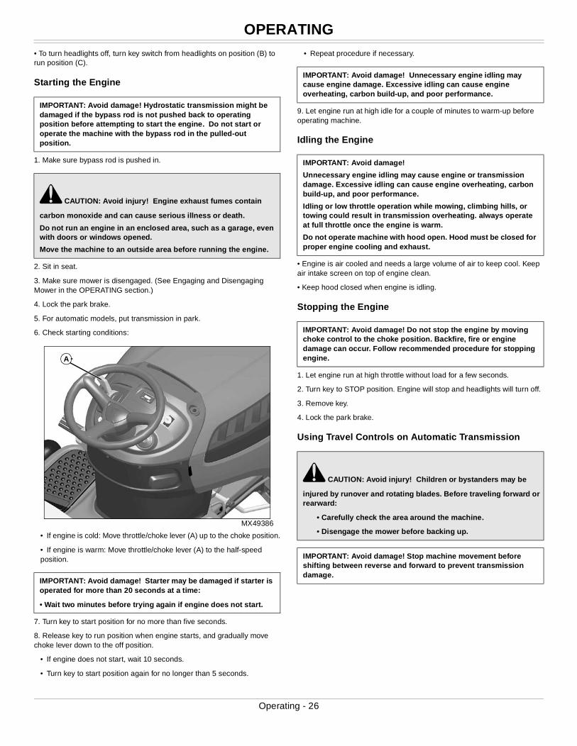
6. Check starting conditions:
MX49386
• If engine is cold: Move throttle/choke lever (A) up to the choke position.
• If engine is warm: Move throttle/choke lever (A) to the half-speed position.
7. Turn key to start position for no more than five seconds.
8. Release key to run position when engine starts, and gradually move choke lever down to the off position.
• If engine does not start, wait 10 seconds.
• Turn key to start position again for no longer than 5 seconds.
• Repeat procedure if necessary.
9. Let engine run at high idle for a couple of minutes to warm-up before operating machine.
Idling the Engine
• Engine is air cooled and needs a large volume of air to keep cool. Keep air intake screen on top of engine clean.
• Keep hood closed when engine is idling.
Stopping the Engine
1. Let engine run at high throttle without load for a few seconds.
2. Turn key to STOP position. Engine will stop and headlights will turn off.
3. Remove key.
4. Lock the park brake.
Using Travel Controls on Automatic Transmission
IMPORTANT: Avoid damage! Hydrostatic transmission might be damaged if the bypass rod is not pushed back to operating position before attempting to start the engine. Do not start or operate the machine with the bypass rod in the pulled-out position.
c CAUTION: Avoid injury! Engine exhaust fumes contain
carbon monoxide and can cause serious illness or death.
Do not run an engine in an enclosed area, such as a garage, even with doors or windows opened.
Move the machine to an outside area before running the engine.
IMPORTANT: Avoid damage! Starter may be damaged if starter is operated for more than 20 seconds at a time:
• Wait two minutes before trying again if engine does not start.
A
IMPORTANT: Avoid damage! Unnecessary engine idling may cause engine damage. Excessive idling can cause engine overheating, carbon build-up, and poor performance.
IMPORTANT: Avoid damage!
Unnecessary engine idling may cause engine or transmission damage. Excessive idling can cause engine overheating, carbon build-up, and poor performance.
Idling or low throttle operation while mowing, climbing hills, or towing could result in transmission overheating. always operate at full throttle once the engine is warm.
Do not operate machine with hood open. Hood must be closed for proper engine cooling and exhaust.
IMPORTANT: Avoid damage! Do not stop the engine by moving choke control to the choke position. Backfire, fire or engine damage can occur. Follow recommended procedure for stopping engine.
c CAUTION: Avoid injury! Children or bystanders may be
injured by runover and rotating blades. Before traveling forward or rearward:
• Carefully check the area around the machine.
• Disengage the mower before backing up.
IMPORTANT: Avoid damage! Stop machine movement before shifting between reverse and forward to prevent transmission damage.
Operating - 26
OPERATING
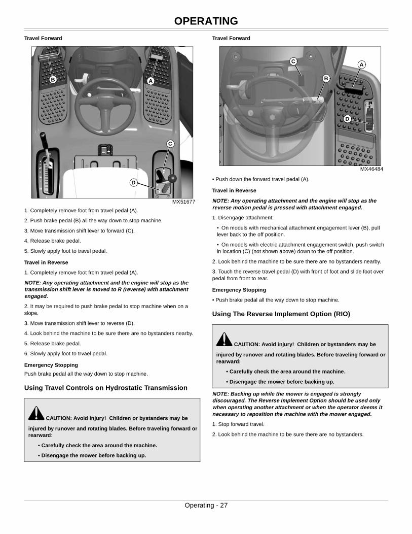
Travel ForwardMX51677
1. Completely remove foot from travel pedal (A).
2. Push brake pedal (B) all the way down to stop machine.
3. Move transmission shift lever to forward (C).
4. Release brake pedal.
5. Slowly apply foot to travel pedal.
Travel in Reverse
1. Completely remove foot from travel pedal (A).
NOTE: Any operating attachment and the engine will stop as the transmission shift lever is moved to R (reverse) with attachment engaged.
2. It may be required to push brake pedal to stop machine when on a slope.
3. Move transmission shift lever to reverse (D).
4. Look behind the machine to be sure there are no bystanders nearby.
5. Release brake pedal.
6. Slowly apply foot to trvael pedal.
Emergency Stopping
Push brake pedal all the way down to stop machine.
Using Travel Controls on Hydrostatic Transmission
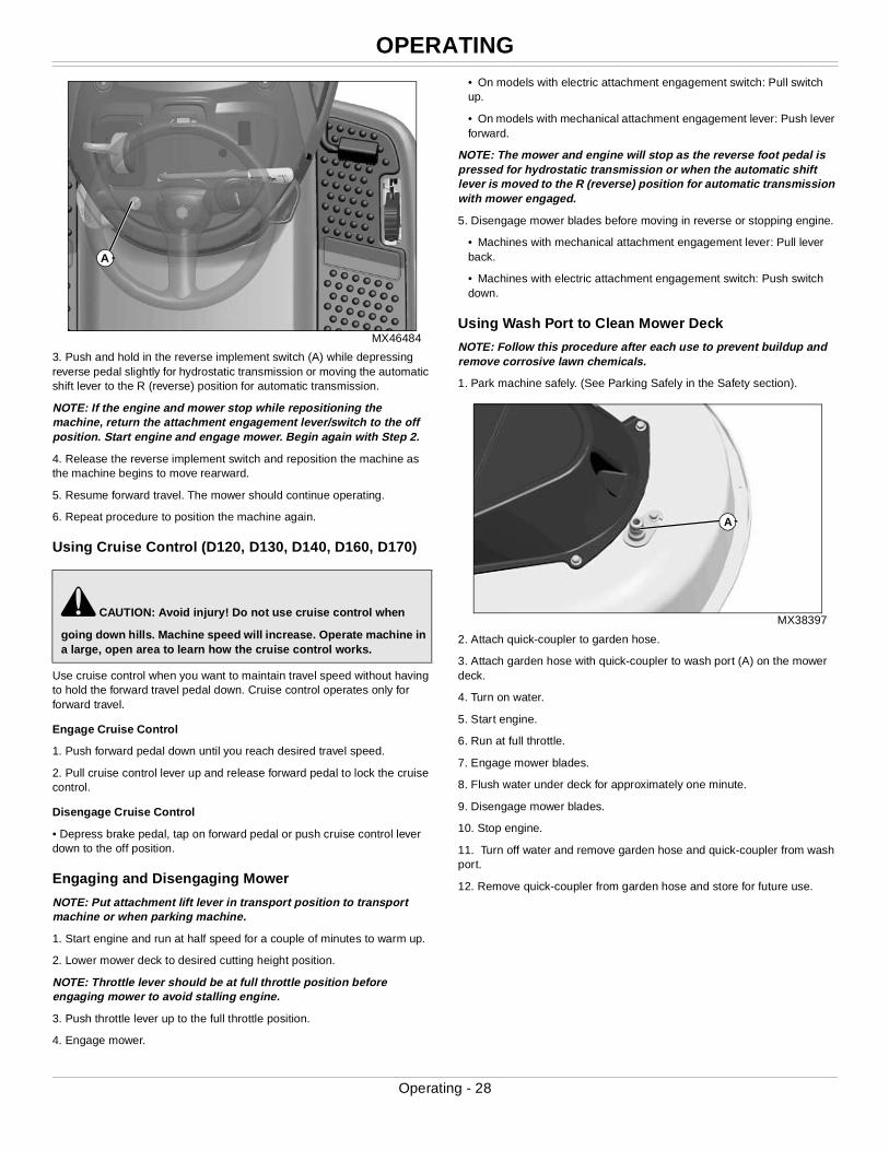
Travel Forward
MX46484
• Push down the forward travel pedal (A).
Travel in Reverse
NOTE: Any operating attachment and the engine will stop as the reverse motion pedal is pressed with attachment engaged.
1. Disengage attachment:
• On models with mechanical attachment engagement lever (B), pull lever back to the off position.
• On models with electric attachment engagement switch, push switch in location (C) (not shown above) down to the off position.
2. Look behind the machine to be sure there are no bystanders nearby.
3. Touch the reverse travel pedal (D) with front of foot and slide foot over pedal from front to rear.
Emergency Stopping
• Push brake pedal all the way down to stop machine.
Using The Reverse Implement Option (RIO)
NOTE: Backing up while the mower is engaged is strongly discouraged. The Reverse Implement Option should be used only when operating another attachment or when the operator deems it necessary to reposition the machine with the mower engaged.
1. Stop forward travel.
2. Look behind the machine to be sure there are no bystanders.
c CAUTION: Avoid injury! Children or bystanders may be
injured by runover and rotating blades. Before traveling forward or rearward:
• Carefully check the area around the machine.
• Disengage the mower before backing up.
C
A
D
B
c CAUTION: Avoid injury! Children or bystanders may be
injured by runover and rotating blades. Before traveling forward or rearward:
• Carefully check the area around the machine.
• Disengage the mower before backing up.
D
A
B
C
Operating - 27
OPERATING
MX46484
3. Push and hold in the reverse implement switch (A) while depressing reverse pedal slightly for hydrostatic transmission or moving the automatic shift lever to the R (reverse) position for automatic transmission.
NOTE: If the engine and mower stop while repositioning the machine, return the attachment engagement lever/switch to the off position. Start engine and engage mower. Begin again with Step 2.
4. Release the reverse implement switch and reposition the machine as the machine begins to move rearward.
5. Resume forward travel. The mower should continue operating.
6. Repeat procedure to position the machine again.
Using Cruise Control (D120, D130, D140, D160, D170)
Use cruise control when you want to maintain travel speed without having to hold the forward travel pedal down. Cruise control operates only for forward travel.
Engage Cruise Control
1. Push forward pedal down until you reach desired travel speed.
2. Pull cruise control lever up and release forward pedal to lock the cruise control.
Disengage Cruise Control
• Depress brake pedal, tap on forward pedal or push cruise control lever down to the off position.
Engaging and Disengaging Mower
NOTE: Put attachment lift lever in transport position to transport machine or when parking machine.
1. Start engine and run at half speed for a couple of minutes to warm up.
2. Lower mower deck to desired cutting height position.
NOTE: Throttle lever should be at full throttle position before engaging mower to avoid stalling engine.
3. Push throttle lever up to the full throttle position.
4. Engage mower.
• On models with electric attachment engagement switch: Pull switch up.
• On models with mechanical attachment engagement lever: Push lever forward.
NOTE: The mower and engine will stop as the reverse foot pedal is pressed for hydrostatic transmission or when the automatic shift lever is moved to the R (reverse) position for automatic transmission with mower engaged.
5. Disengage mower blades before moving in reverse or stopping engine.
• Machines with mechanical attachment engagement lever: Pull lever back.
• Machines with electric attachment engagement switch: Push switch down.
Using Wash Port to Clean Mower Deck
NOTE: Follow this procedure after each use to prevent buildup and remove corrosive lawn chemicals.
1. Park machine safely. (See Parking Safely in the Safety section).
MX38397
2. Attach quick-coupler to garden hose.
3. Attach garden hose with quick-coupler to wash port (A) on the mower deck.
4. Turn on water.
5. Start engine.
6. Run at full throttle.
7. Engage mower blades.
8. Flush water under deck for approximately one minute.
9. Disengage mower blades.
10. Stop engine.
11. Turn off water and remove garden hose and quick-coupler from wash port.
12. Remove quick-coupler from garden hose and store for future use.
c CAUTION: Avoid injury! Do not use cruise control when
going down hills. Machine speed will increase. Operate machine in a large, open area to learn how the cruise control works.
A
A
Operating - 28
OPERATING
Unplugging Mower, Bagger, or Material Collection System
Checking For Plugging While Driving
If grass builds up in front of mower discharge chute, check for plugged chute or problems with blower assembly (if equipped).
If there is a trail of clippings behind mower or clippings blow to the side, check for plugged chute, full collector bags, or problems with blower assembly.
Removing Debris From Inspection Points:
1. Park machine safely. Wait for all moving parts to stop before getting off to inspect machine.
2. Open hopper cover. Check chute outlet.
3. Remove chute from mower deck or blower assembly. Check chute inlet.
4. Check under mower deck for debris.
Moving Machine by Hand
1. Unlock the park brake.
2. Put automatic transmission in P (park).
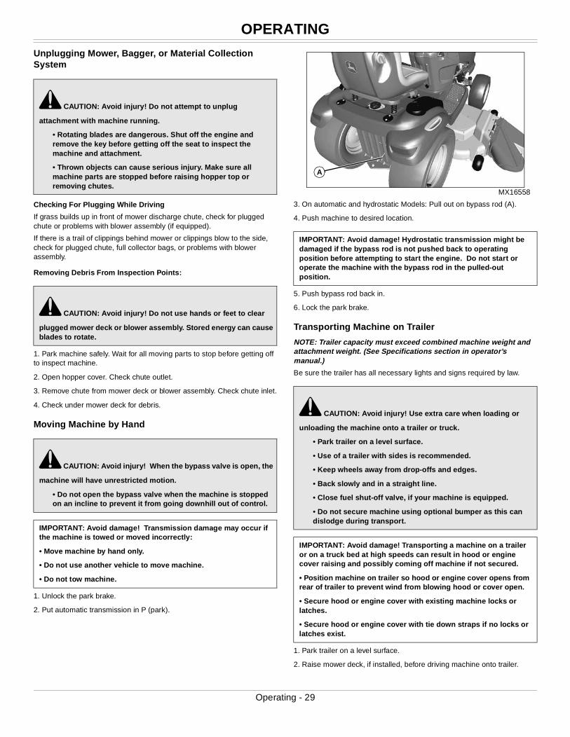
MX16558
3. On automatic and hydrostatic Models: Pull out on bypass rod (A).
4. Push machine to desired location.
5. Push bypass rod back in.
6. Lock the park brake.
Transporting Machine on Trailer
NOTE: Trailer capacity must exceed combined machine weight and attachment weight. (See Specifications section in operator’s manual.)
Be sure the trailer has all necessary lights and signs required by law.
1. Park trailer on a level surface.
2. Raise mower deck, if installed, before driving machine onto trailer.
c CAUTION: Avoid injury! Do not attempt to unplug
attachment with machine running.
• Rotating blades are dangerous. Shut off the engine and remove the key before getting off the seat to inspect the machine and attachment.
• Thrown objects can cause serious injury. Make sure all machine parts are stopped before raising hopper top or removing chutes.
c CAUTION: Avoid injury! Do not use hands or feet to clear
plugged mower deck or blower assembly. Stored energy can cause blades to rotate.
c CAUTION: Avoid injury! When the bypass valve is open, the
machine will have unrestricted motion.
• Do not open the bypass valve when the machine is stopped on an incline to prevent it from going downhill out of control.
IMPORTANT: Avoid damage! Transmission damage may occur if the machine is towed or moved incorrectly:
• Move machine by hand only.
• Do not use another vehicle to move machine.
• Do not tow machine.
IMPORTANT: Avoid damage! Hydrostatic transmission might be damaged if the bypass rod is not pushed back to operating position before attempting to start the engine. Do not start or operate the machine with the bypass rod in the pulled-out position.
c CAUTION: Avoid injury! Use extra care when loading or
unloading the machine onto a trailer or truck.
• Park trailer on a level surface.
• Use of a trailer with sides is recommended.
• Keep wheels away from drop-offs and edges.
• Back slowly and in a straight line.
• Close fuel shut-off valve, if your machine is equipped.
• Do not secure machine using optional bumper as this can dislodge during transport.
IMPORTANT: Avoid damage! Transporting a machine on a trailer or on a truck bed at high speeds can result in hood or engine cover raising and possibly coming off machine if not secured.
• Position machine on trailer so hood or engine cover opens from rear of trailer to prevent wind from blowing hood or cover open.
• Secure hood or engine cover with existing machine locks or latches.
• Secure hood or engine cover with tie down straps if no locks or latches exist.
A
Operating - 29
OPERATING
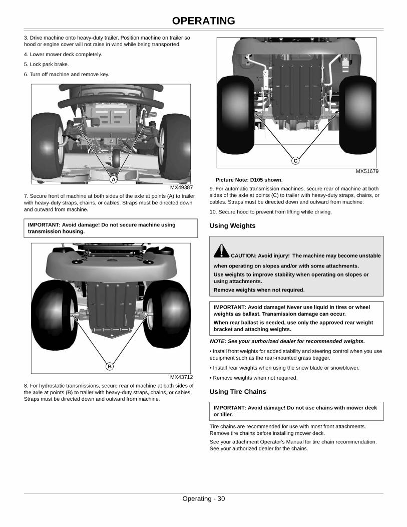
3. Drive machine onto heavy-duty trailer. Position machine on trailer so hood or engine cover will not raise in wind while being transported.4. Lower mower deck completely.
5. Lock park brake.
6. Turn off machine and remove key.
MX49387
7. Secure front of machine at both sides of the axle at points (A) to trailer with heavy-duty straps, chains, or cables. Straps must be directed down and outward from machine.
MX43712
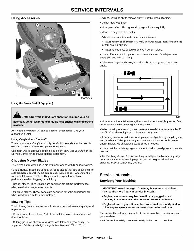
8. For hydrostatic transmissions, secure rear of machine at both sides of the axle at points (B) to trailer with heavy-duty straps, chains, or cables. Straps must be directed down and outward from machine.
MX51679
Picture Note: D105 shown.
9. For automatic transmission machines, secure rear of machine at both sides of the axle at points (C) to trailer with heavy-duty straps, chains, or cables. Straps must be directed down and outward from machine.
10. Secure hood to prevent from lifting while driving.
Using Weights
NOTE: See your authorized dealer for recommended weights.
• Install front weights for added stability and steering control when you use equipment such as the rear-mounted grass bagger.
• Install rear weights when using the snow blade or snowblower.
• Remove weights when not required.
Using Tire Chains
Tire chains are recommended for use with most front attachments. Remove tire chains before installing mower deck.
See your attachment Operator’s Manual for tire chain recommendation. See your authorized dealer for the chains.
IMPORTANT: Avoid damage! Do not secure machine using transmission housing.
A
B
c CAUTION: Avoid injury! The machine may become unstable
when operating on slopes and/or with some attachments.
Use weights to improve stability when operating on slopes or using attachments.
Remove weights when not required.
IMPORTANT: Avoid damage! Never use liquid in tires or wheel weights as ballast. Transmission damage can occur.
When rear ballast is needed, use only the approved rear weight bracket and attaching weights.
IMPORTANT: Avoid damage! Do not use chains with mower deck or tiller.
C
Operating - 30
SERVICE INTERVALS
Using Accessories
MX46479
Using the Power Port (If Equipped)
An electric power port (A) can be used for accessories. See your authorized dealer.
Using CargO Mount System™
The front and rear CargO Mount System™ brackets (B) can be used for easy attachment of selected optional equipment.
Use John Deere approved optional equipment only. See your Authorized Service Center for approved optional equipment.
Choosing Mower BladesThree types of mower blades are available for use with D series mowers.
• 3-N-1 blades. These are general purpose blades that are best suited for side-discharge operation, but can be used with a bagger attachment, or with a mulch cover installed. They are not designed for optimal performance when bagging or mulching.
• Bagger blades. These blades are designed for optimal performance when used with bagger attachments.
• Mulching blades. These blades are designed for optimal performance when used with a mulch cover installed.
Mowing TipsThe following recommendations will produce the best lawn cut quality and appearance:
• Keep mower blades sharp. Dull blades will tear grass; tips of grass will then turn brown.
• Cutting grass too short may kill grass and let weeds grow easily. The suggested finished cut height range is 44 - 70 mm (1.75 - 2.75 in.).
• Adjust cutting height to remove only 1/3 of the grass at a time.
• Do not mow wet grass.
• Mow grass often. Short grass clippings will decay quickly.
• Mow with engine at full throttle.
• Adjust travel speed to match mowing conditions:
• Travel at slow speed when you mow thick, tall grass, make sharp turns or trim around objects.
• Travel at moderate speed when you mow thin grass.
• Use a different mowing pattern each time you mow. Overlap mowing paths 50 - 100 mm (2 - 4 in.).
• Drive over ridges and through shallow ditches straight-on, not at an angle.
MIF
• Mow around the outside twice, then mow inside in straight passes. Best cut is achieved when mowing in a straight line.
• When mowing or mulching near pavement, overlap the pavement by 50 mm (2 in.) to allow clippings to dispense over grass.
• A thick layer of mulched leaves can prevent sunlight from getting to grass and smother it. Taller grass heights allow mulched leaves to dispense easier in lawn. Mulch leaves several times if needed.
• Use a thatcher in late spring or summer to pull up dead grass and aerate ground.
• For Mulching Mower: Shorter cut heights will provide better cut quality, but may leave noticeable clippings. Higher cut heights will reduce clippings, but cut quality may decline.
Service IntervalsServicing Your Machine
Please use the following timetables to perform routine maintenance on your machine.
Park the vehicle safely. See Park Safely in the SAFETY Section.
c CAUTION: Avoid injury! Safe operation requires your full
attention. Do not wear radio or music headphones while operating machine.
A
B
B
IMPORTANT: Avoid damage! Operating in extreme conditions may require more frequent service intervals:
• Engine components may become dirty or plugged when operating in extreme heat, dust or other severe conditions.
• Engine oil can degrade if machine is operated constantly at slow or low engine speeds or for frequent short periods of time.
Service Intervals - 31
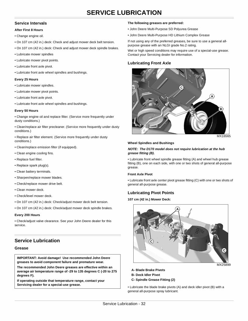
SERVICE LUBRICATION
Service Intervals
After First 8 Hours
• Change engine oil.
• On 107 cm (42 in.) deck: Check and adjust mower deck belt tension.
• On 107 cm (42 in.) deck: Check and adjust mower deck spindle brakes.
• Lubricate mower spindles
• Lubricate mower pivot points.
• Lubricate front axle pivot.
• Lubricate front axle wheel spindles and bushings.
Every 25 Hours
• Lubricate mower spindles.
• Lubricate mower pivot points.
• Lubricate front axle pivot.
• Lubricate front axle wheel spindles and bushings.
Every 50 Hours
• Change engine oil and replace filter. (Service more frequently under dusty conditions.)
• Clean/replace air filter precleaner. (Service more frequently under dusty conditions.)
• Replace air filter element. (Service more frequently under dusty conditions.)
• Clean/replace emission filter (if equipped).
• Clean engine cooling fins.
• Replace fuel filter.
• Replace spark plug(s).
• Clean battery terminals.
• Sharpen/replace mower blades.
• Check/replace mower drive belt.
• Clean mower deck.
• Check/level mower deck.
• On 107 cm (42 in.) deck: Check/adjust mower deck belt tension.
• On 107 cm (42 in.) deck: Check/adjust mower deck spindle brakes.
Every 200 Hours
• Check/adjust valve clearance. See your John Deere dealer for this service.
Service LubricationGrease
The following greases are preferred:
• John Deere Multi-Purpose SD Polyurea Grease
• John Deere Multi-Purpose HD Lithium Complex Grease
If not using any of the preferred greases, be sure to use a general all-purpose grease with an NLGI grade No.2 rating.
Wet or high speed conditions may require use of a special-use grease. Contact your Servicing dealer for information.
Lubricating Front Axle
MX16565
Wheel Spindles and Bushings
NOTE: The D170 model does not require lubrication at the hub grease fitting (B).
• Lubricate front wheel spindle grease fitting (A) and wheel hub grease fitting (B), one on each side, with one or two shots of general all-purpose grease.
Front Axle Pivot
• Lubricate front axle center pivot grease fitting (C) with one or two shots of general all-purpose grease.
Lubricating Pivot Points
107 cm (42 in.) Mower Deck:
MX25899
A- Blade Brake Pivots
B- Deck Idler Pivot
C- Spindle Grease Fitting (2)
• Lubricate the blade brake pivots (A) and deck idler pivot (B) with a general all-purpose spray lubricant.
IMPORTANT: Avoid damage! Use recommended John Deere greases to avoid component failure and premature wear.
The recommended John Deere greases are effective within an average air temperature range of -29 to 135 degrees C (-20 to 275 degrees F).
If operating outside that temperature range, contact your Servicing dealer for a special-use grease.
C
A
B
A
B
C
C
Service Lubrication - 32
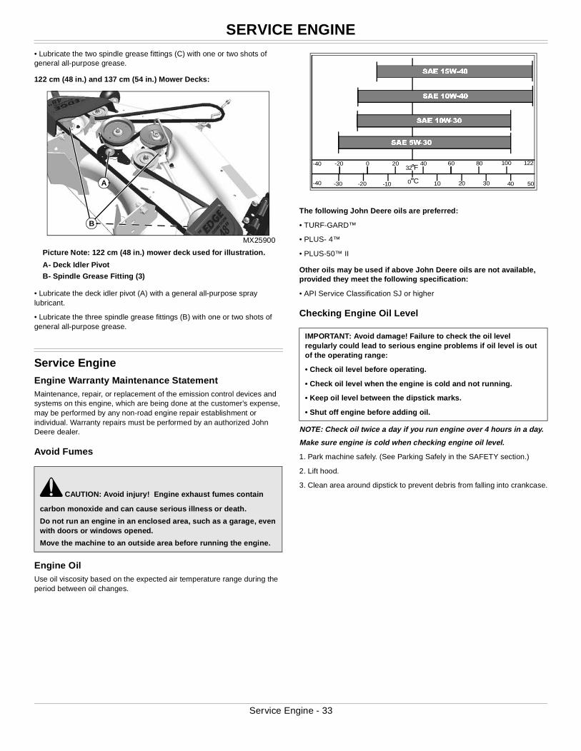
SERVICE ENGINE
• Lubricate the two spindle grease fittings (C) with one or two shots of general all-purpose grease.122 cm (48 in.) and 137 cm (54 in.) Mower Decks:
MX25900
Picture Note: 122 cm (48 in.) mower deck used for illustration.
A- Deck Idler Pivot
B- Spindle Grease Fitting (3)
• Lubricate the deck idler pivot (A) with a general all-purpose spray lubricant.
• Lubricate the three spindle grease fittings (B) with one or two shots of general all-purpose grease.
Service EngineEngine Warranty Maintenance StatementMaintenance, repair, or replacement of the emission control devices and systems on this engine, which are being done at the customer’s expense, may be performed by any non-road engine repair establishment or individual. Warranty repairs must be performed by an authorized John Deere dealer.
Avoid Fumes
Engine OilUse oil viscosity based on the expected air temperature range during the period between oil changes.
The following John Deere oils are preferred:
• TURF-GARD™
• PLUS- 4™
• PLUS-50™ II
Other oils may be used if above John Deere oils are not available, provided they meet the following specification:
• API Service Classification SJ or higher
Checking Engine Oil Level
NOTE: Check oil twice a day if you run engine over 4 hours in a day.
Make sure engine is cold when checking engine oil level.
1. Park machine safely. (See Parking Safely in the SAFETY section.)
2. Lift hood.
3. Clean area around dipstick to prevent debris from falling into crankcase.c CAUTION: Avoid injury! Engine exhaust fumes contain
carbon monoxide and can cause serious illness or death.
Do not run an engine in an enclosed area, such as a garage, even with doors or windows opened.
Move the machine to an outside area before running the engine.
B
A
IMPORTANT: Avoid damage! Failure to check the oil level regularly could lead to serious engine problems if oil level is out of the operating range:
• Check oil level before operating.
• Check oil level when the engine is cold and not running.
• Keep oil level between the dipstick marks.
• Shut off engine before adding oil.
32
0 10 20 30 40-10-20-30
-20 0 20 40 60 80 100
50
122
-40
-40F
C
SAE 5W-30
SAE 10W-30
SAE 10W-40
SAE 15W-40
Service Engine - 33
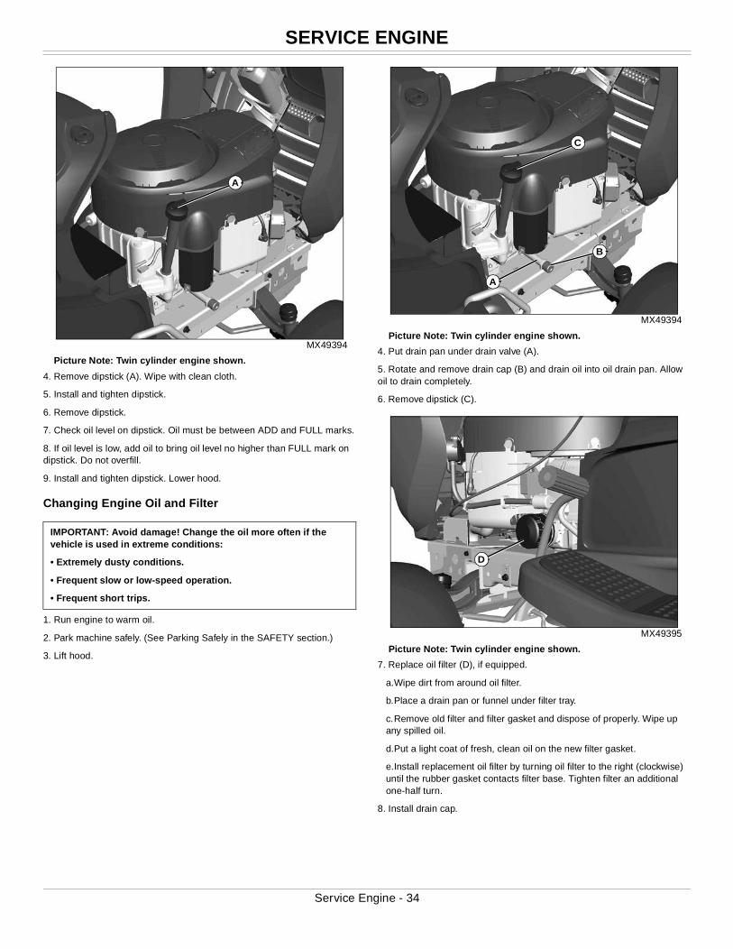
SERVICE ENGINE
MX49394
Picture Note: Twin cylinder engine shown.
4. Remove dipstick (A). Wipe with clean cloth.
5. Install and tighten dipstick.
6. Remove dipstick.
7. Check oil level on dipstick. Oil must be between ADD and FULL marks.
8. If oil level is low, add oil to bring oil level no higher than FULL mark on dipstick. Do not overfill.
9. Install and tighten dipstick. Lower hood.
Changing Engine Oil and Filter
1. Run engine to warm oil.
2. Park machine safely. (See Parking Safely in the SAFETY section.)
3. Lift hood.
MX49394
Picture Note: Twin cylinder engine shown.
4. Put drain pan under drain valve (A).
5. Rotate and remove drain cap (B) and drain oil into oil drain pan. Allow oil to drain completely.
6. Remove dipstick (C).
MX49395
Picture Note: Twin cylinder engine shown.
7. Replace oil filter (D), if equipped.
a.Wipe dirt from around oil filter.
b.Place a drain pan or funnel under filter tray.
c.Remove old filter and filter gasket and dispose of properly. Wipe up any spilled oil.
d.Put a light coat of fresh, clean oil on the new filter gasket.
e.Install replacement oil filter by turning oil filter to the right (clockwise) until the rubber gasket contacts filter base. Tighten filter an additional one-half turn.
8. Install drain cap.
IMPORTANT: Avoid damage! Change the oil more often if the vehicle is used in extreme conditions:
• Extremely dusty conditions.
• Frequent slow or low-speed operation.
• Frequent short trips.
A
B
A
C
D
Service Engine - 34
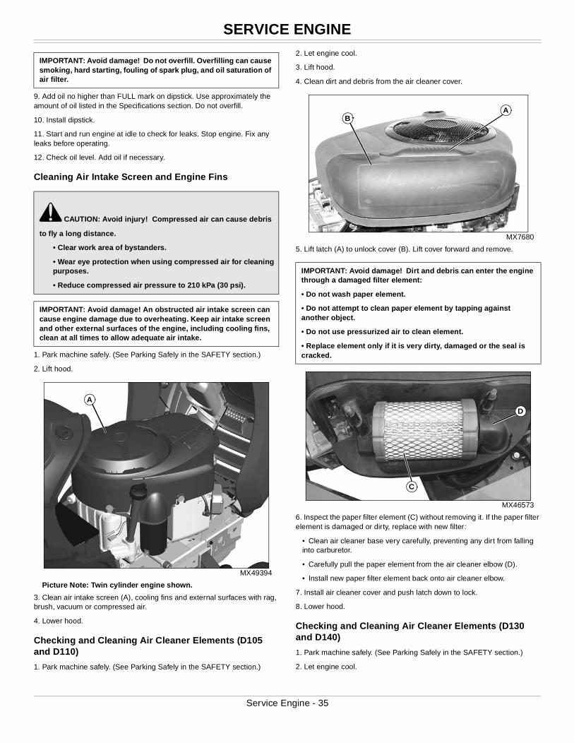
SERVICE ENGINE
9. Add oil no higher than FULL mark on dipstick. Use approximately the amount of oil listed in the Specifications section. Do not overfill.
10. Install dipstick.
11. Start and run engine at idle to check for leaks. Stop engine. Fix any leaks before operating.
12. Check oil level. Add oil if necessary.
Cleaning Air Intake Screen and Engine Fins
1. Park machine safely. (See Parking Safely in the SAFETY section.)
2. Lift hood.
MX49394
Picture Note: Twin cylinder engine shown.
3. Clean air intake screen (A), cooling fins and external surfaces with rag, brush, vacuum or compressed air.
4. Lower hood.
Checking and Cleaning Air Cleaner Elements (D105 and D110)
1. Park machine safely. (See Parking Safely in the SAFETY section.)
2. Let engine cool.
3. Lift hood.
4. Clean dirt and debris from the air cleaner cover.
MX7680
5. Lift latch (A) to unlock cover (B). Lift cover forward and remove.
MX46573
6. Inspect the paper filter element (C) without removing it. If the paper filter element is damaged or dirty, replace with new filter:
• Clean air cleaner base very carefully, preventing any dirt from falling into carburetor.
• Carefully pull the paper element from the air cleaner elbow (D).
• Install new paper filter element back onto air cleaner elbow.
7. Install air cleaner cover and push latch down to lock.
8. Lower hood.
Checking and Cleaning Air Cleaner Elements (D130 and D140)
1. Park machine safely. (See Parking Safely in the SAFETY section.)
2. Let engine cool.
IMPORTANT: Avoid damage! Do not overfill. Overfilling can cause smoking, hard starting, fouling of spark plug, and oil saturation of air filter.
c CAUTION: Avoid injury! Compressed air can cause debris
to fly a long distance.
• Clear work area of bystanders.
• Wear eye protection when using compressed air for cleaning purposes.
• Reduce compressed air pressure to 210 kPa (30 psi).
IMPORTANT: Avoid damage! An obstructed air intake screen can cause engine damage due to overheating. Keep air intake screen and other external surfaces of the engine, including cooling fins, clean at all times to allow adequate air intake.
A
IMPORTANT: Avoid damage! Dirt and debris can enter the engine through a damaged filter element:
• Do not wash paper element.
• Do not attempt to clean paper element by tapping against another object.
• Do not use pressurized air to clean element.
• Replace element only if it is very dirty, damaged or the seal is cracked.
BA
D
C
Service Engine - 35
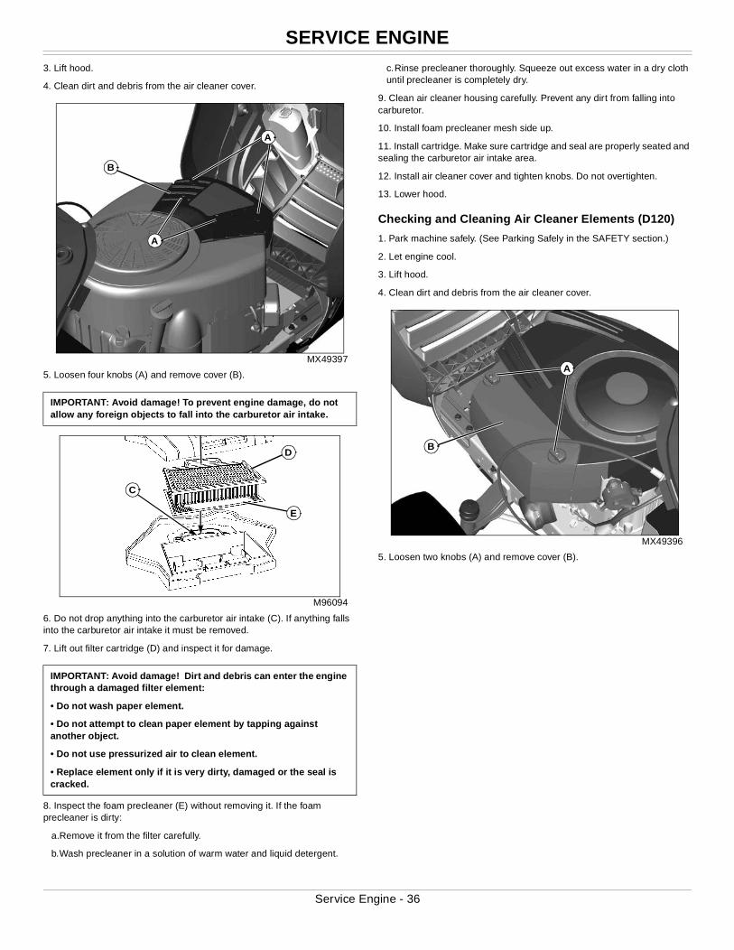
SERVICE ENGINE
3. Lift hood.4. Clean dirt and debris from the air cleaner cover.
MX49397
5. Loosen four knobs (A) and remove cover (B).
M96094
6. Do not drop anything into the carburetor air intake (C). If anything falls into the carburetor air intake it must be removed.
7. Lift out filter cartridge (D) and inspect it for damage.
8. Inspect the foam precleaner (E) without removing it. If the foam precleaner is dirty:
a.Remove it from the filter carefully.
b.Wash precleaner in a solution of warm water and liquid detergent.
c.Rinse precleaner thoroughly. Squeeze out excess water in a dry cloth until precleaner is completely dry.
9. Clean air cleaner housing carefully. Prevent any dirt from falling into carburetor.
10. Install foam precleaner mesh side up.
11. Install cartridge. Make sure cartridge and seal are properly seated and sealing the carburetor air intake area.
12. Install air cleaner cover and tighten knobs. Do not overtighten.
13. Lower hood.
Checking and Cleaning Air Cleaner Elements (D120)
1. Park machine safely. (See Parking Safely in the SAFETY section.)
2. Let engine cool.
3. Lift hood.
4. Clean dirt and debris from the air cleaner cover.
MX49396
5. Loosen two knobs (A) and remove cover (B).
IMPORTANT: Avoid damage! To prevent engine damage, do not allow any foreign objects to fall into the carburetor air intake.
IMPORTANT: Avoid damage! Dirt and debris can enter the engine through a damaged filter element:
• Do not wash paper element.
• Do not attempt to clean paper element by tapping against another object.
• Do not use pressurized air to clean element.
• Replace element only if it is very dirty, damaged or the seal is cracked.
A
A
B
D
E
C
B
A
Service Engine - 36
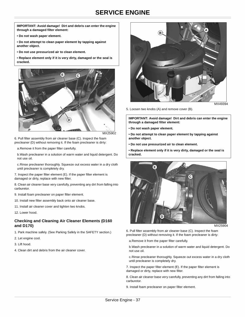
SERVICE ENGINE
MX25902
6. Pull filter assembly from air cleaner base (C). Inspect the foam precleaner (D) without removing it. If the foam precleaner is dirty:
a.Remove it from the paper filter carefully.
b.Wash precleaner in a solution of warm water and liquid detergent. Do not use oil.
c.Rinse precleaner thoroughly. Squeeze out excess water in a dry cloth until precleaner is completely dry.
7. Inspect the paper filter element (E). If the paper filter element is damaged or dirty, replace with new filter.
8. Clean air cleaner base very carefully, preventing any dirt from falling into carburetor.
9. Install foam precleaner on paper filter element.
10. Install new filter assembly back onto air cleaner base.
11. Install air cleaner cover and tighten two knobs.
12. Lower hood.
Checking and Cleaning Air Cleaner Elements (D160 and D170)
1. Park machine safely. (See Parking Safely in the SAFETY section.)
2. Let engine cool.
3. Lift hood.
4. Clean dirt and debris from the air cleaner cover.
MX49394
5. Loosen two knobs (A) and remove cover (B).
MX25904
6. Pull filter assembly from air cleaner base (C). Inspect the foam precleaner (D) without removing it. If the foam precleaner is dirty:
a.Remove it from the paper filter carefully.
b.Wash precleaner in a solution of warm water and liquid detergent. Do not use oil.
c.Rinse precleaner thoroughly. Squeeze out excess water in a dry cloth until precleaner is completely dry.
7. Inspect the paper filter element (E). If the paper filter element is damaged or dirty, replace with new filter.
8. Clean air cleaner base very carefully, preventing any dirt from falling into carburetor.
9. Install foam precleaner on paper filter element.
IMPORTANT: Avoid damage! Dirt and debris can enter the engine through a damaged filter element:
• Do not wash paper element.
• Do not attempt to clean paper element by tapping against another object.
• Do not use pressurized air to clean element.
• Replace element only if it is very dirty, damaged or the seal is cracked.
E C
D IMPORTANT: Avoid damage! Dirt and debris can enter the engine through a damaged filter element:
• Do not wash paper element.
• Do not attempt to clean paper element by tapping against another object.
• Do not use pressurized air to clean element.
• Replace element only if it is very dirty, damaged or the seal is cracked.
BA
E
C
D
Service Engine - 37
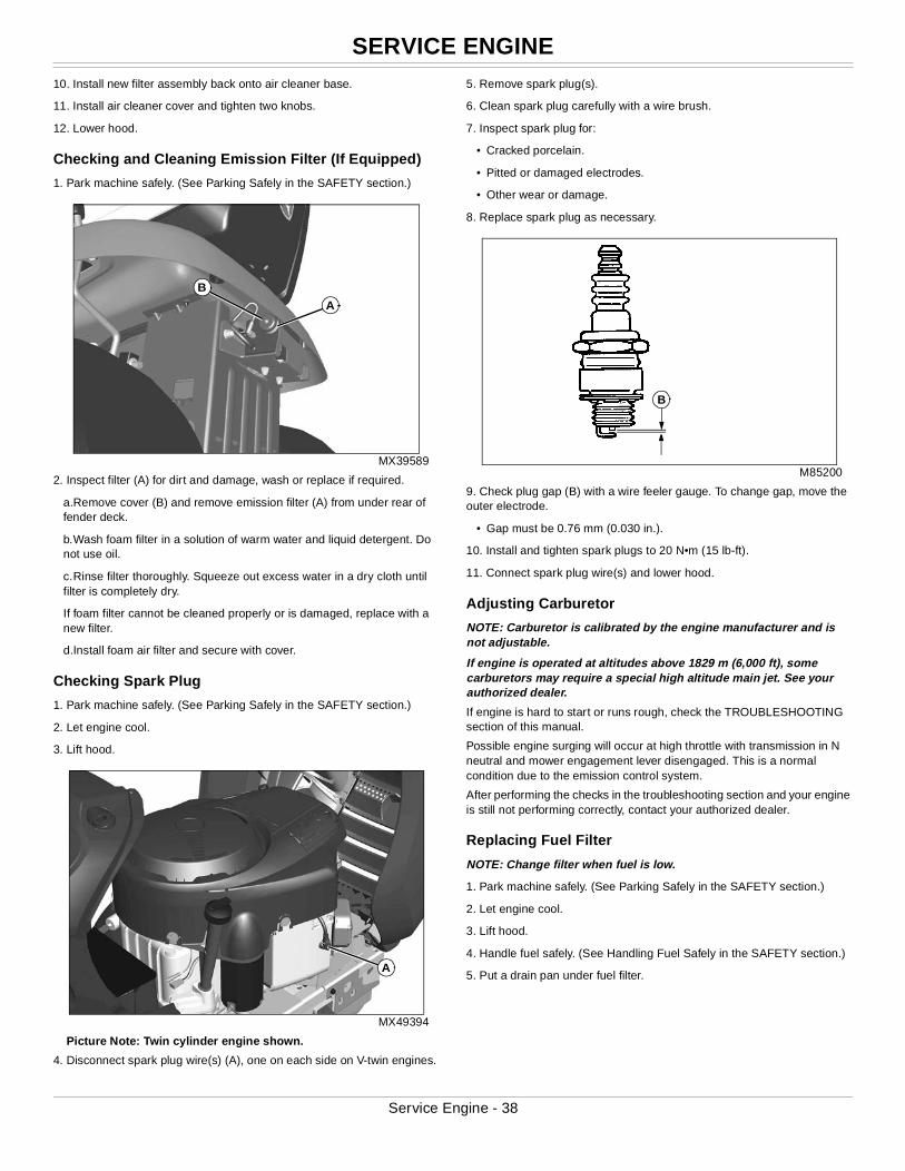
SERVICE ENGINE
10. Install new filter assembly back onto air cleaner base.11. Install air cleaner cover and tighten two knobs.
12. Lower hood.
Checking and Cleaning Emission Filter (If Equipped)
1. Park machine safely. (See Parking Safely in the SAFETY section.)
MX39589
2. Inspect filter (A) for dirt and damage, wash or replace if required.
a.Remove cover (B) and remove emission filter (A) from under rear of fender deck.
b.Wash foam filter in a solution of warm water and liquid detergent. Do not use oil.
c.Rinse filter thoroughly. Squeeze out excess water in a dry cloth until filter is completely dry.
If foam filter cannot be cleaned properly or is damaged, replace with a new filter.
d.Install foam air filter and secure with cover.
Checking Spark Plug
1. Park machine safely. (See Parking Safely in the SAFETY section.)
2. Let engine cool.
3. Lift hood.
MX49394
Picture Note: Twin cylinder engine shown.
4. Disconnect spark plug wire(s) (A), one on each side on V-twin engines.
5. Remove spark plug(s).
6. Clean spark plug carefully with a wire brush.
7. Inspect spark plug for:
• Cracked porcelain.
• Pitted or damaged electrodes.
• Other wear or damage.
8. Replace spark plug as necessary.
M85200
9. Check plug gap (B) with a wire feeler gauge. To change gap, move the outer electrode.
• Gap must be 0.76 mm (0.030 in.).
10. Install and tighten spark plugs to 20 N•m (15 lb-ft).
11. Connect spark plug wire(s) and lower hood.
Adjusting Carburetor
NOTE: Carburetor is calibrated by the engine manufacturer and is not adjustable.
If engine is operated at altitudes above 1829 m (6,000 ft), some carburetors may require a special high altitude main jet. See your authorized dealer.
If engine is hard to start or runs rough, check the TROUBLESHOOTING section of this manual.
Possible engine surging will occur at high throttle with transmission in N neutral and mower engagement lever disengaged. This is a normal condition due to the emission control system.
After performing the checks in the troubleshooting section and your engine is still not performing correctly, contact your authorized dealer.
Replacing Fuel Filter
NOTE: Change filter when fuel is low.
1. Park machine safely. (See Parking Safely in the SAFETY section.)
2. Let engine cool.
3. Lift hood.
4. Handle fuel safely. (See Handling Fuel Safely in the SAFETY section.)
5. Put a drain pan under fuel filter.
B
A
A
B
Service Engine - 38
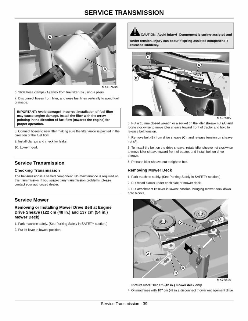
SERVICE TRANSMISSION
MX13768b
6. Slide hose clamps (A) away from fuel filter (B) using a pliers.
7. Disconnect hoses from filter, and raise fuel lines vertically to avoid fuel drainage.
8. Connect hoses to new filter making sure the filter arrow is pointed in the direction of the fuel flow.
9. Install clamps and check for leaks.
10. Lower hood.
Service Transmission Checking TransmissionThe transmission is a sealed component. No maintenance is required on this transmission. If you suspect any transmission problems, please contact your authorized dealer.
Service MowerRemoving or Installing Mower Drive Belt at Engine Drive Sheave (122 cm (48 in.) and 137 cm (54 in.) Mower Deck)
1. Park machine safely. (See Parking Safely in SAFETY section.)
2. Put lift lever in lowest position.
MX25905
3. Put a 15 mm closed wrench or a socket on the idler sheave nut (A) and rotate clockwise to move idler sheave toward front of tractor and hold to release belt tension.
4. Remove belt (B) from drive sheave (C), and release tension on sheave nut (A).
5. To install the belt on the drive sheave, rotate idler sheave nut clockwise to move idler sheave toward front of tractor, and install belt on drive sheave.
6. Release idler sheave nut to tighten belt.
Removing Mower Deck
1. Park machine safely. (See Parking Safely in SAFETY section.)
2. Put wood blocks under each side of mower deck.
3. Put attachment lift lever in lowest position, bringing mower deck down onto blocks.
MX7681a
Picture Note: 107 cm (42 in.) mower deck only.
4. On machines with 107 cm (42 in.), disconnect mower engagement drive
IMPORTANT: Avoid damage! Incorrect installation of fuel filter may cause engine damage. Install the filter with the arrow pointing in the direction of fuel flow (towards the engine) for proper operation.
A
B
c CAUTION: Avoid injury! Component is spring-assisted and
under tension. Injury can occur if spring-assisted component is released suddenly.
B
A
C
E
B
A
C
D
Service Transmission - 39
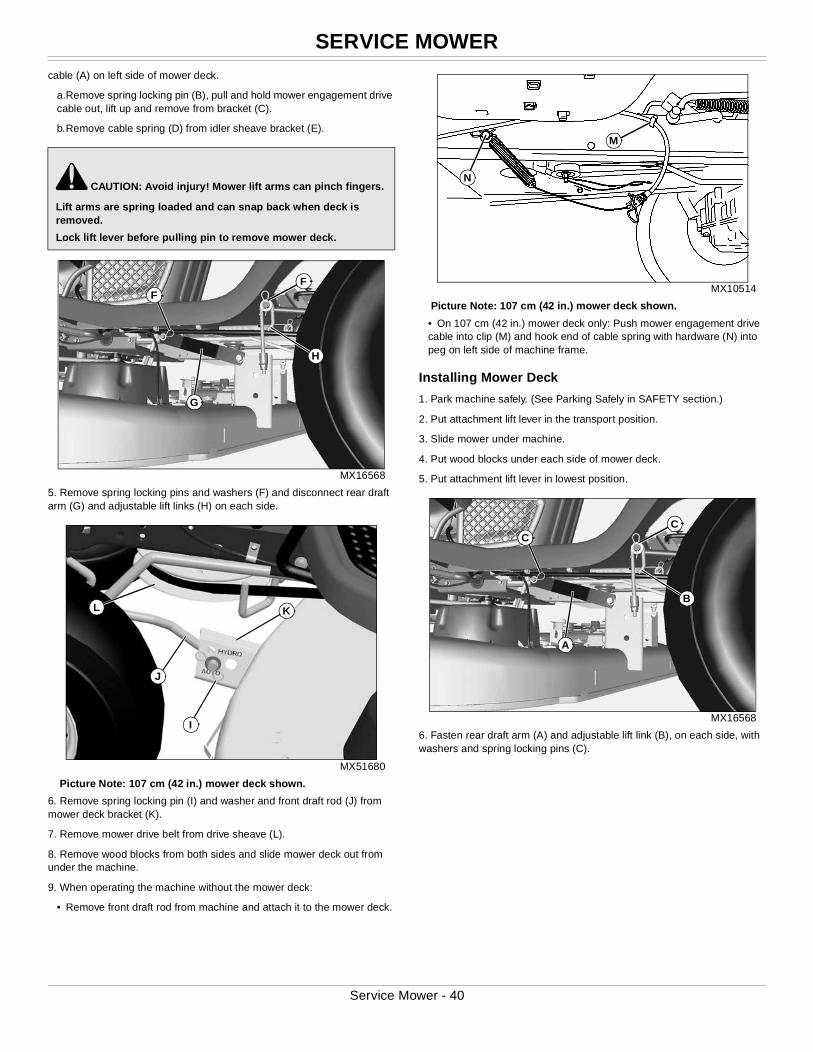
SERVICE MOWER
cable (A) on left side of mower deck.a.Remove spring locking pin (B), pull and hold mower engagement drive cable out, lift up and remove from bracket (C).
b.Remove cable spring (D) from idler sheave bracket (E).
MX16568
5. Remove spring locking pins and washers (F) and disconnect rear draft arm (G) and adjustable lift links (H) on each side.
MX51680
Picture Note: 107 cm (42 in.) mower deck shown.
6. Remove spring locking pin (I) and washer and front draft rod (J) from mower deck bracket (K).
7. Remove mower drive belt from drive sheave (L).
8. Remove wood blocks from both sides and slide mower deck out from under the machine.
9. When operating the machine without the mower deck:
• Remove front draft rod from machine and attach it to the mower deck.
MX10514
Picture Note: 107 cm (42 in.) mower deck shown.
• On 107 cm (42 in.) mower deck only: Push mower engagement drive cable into clip (M) and hook end of cable spring with hardware (N) into peg on left side of machine frame.
Installing Mower Deck
1. Park machine safely. (See Parking Safely in SAFETY section.)
2. Put attachment lift lever in the transport position.
3. Slide mower under machine.
4. Put wood blocks under each side of mower deck.
5. Put attachment lift lever in lowest position.
MX16568
6. Fasten rear draft arm (A) and adjustable lift link (B), on each side, with washers and spring locking pins (C).
c CAUTION: Avoid injury! Mower lift arms can pinch fingers.
Lift arms are spring loaded and can snap back when deck is removed.
Lock lift lever before pulling pin to remove mower deck.
G
FF
H
J
K
I
L
M
N
A
CC
B
Service Mower - 40
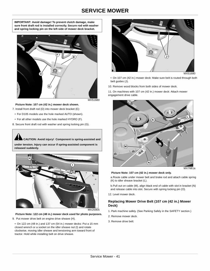
SERVICE MOWER
MX51680
Picture Note: 107 cm (42 in.) mower deck shown.
7. Install front draft rod (D) into mower deck bracket (E):
• For D105 models use the hole marked AUTO (shown).
• For all other models use the hole marked HYDRO (F).
8. Secure front draft rod with washer and spring locking pin (G).
MX25905
Picture Note: 122 cm (48 in.) mower deck used for photo purposes.
9. Put mower drive belt on engine drive sheave (H).
• On 122 cm (48 in.) and 137 cm (54 in.) mower decks: Put a 15 mm closed wrench or a socket on the idler sheave nut (I) and rotate clockwise, moving idler sheave and tensioning arm toward front of tractor. Hold while installing belt on drive sheave.
MX51680
• On 107 cm (42 in.) mower deck: Make sure belt is routed through both belt guides (J).
10. Remove wood blocks from both sides of mower deck.
11. On machines with 107 cm (42 in.) mower deck: Attach mower engagement drive cable.
MX7681a
Picture Note: 107 cm (42 in.) mower deck only.
a.Route cable under mower belt and brake rod and attach cable spring (K) to idler sheave bracket (L).
b.Pull out on cable (M), align black end of cable with slot in bracket (N) and release cable into slot. Secure with spring locking pin (O).
12. Level mower deck.
Replacing Mower Drive Belt (107 cm (42 in.) Mower Deck)
1. Park machine safely. (See Parking Safely in the SAFETY section.)
2. Remove mower deck.
3. Remove drive belt:
IMPORTANT: Avoid damage! To prevent clutch damage, make sure front draft rod is installed correctly. Secure rod with washer and spring locking pin on the left side of mower deck bracket.
c CAUTION: Avoid injury! Component is spring-assisted and
under tension. Injury can occur if spring-assisted component is released suddenly.
D
E
G
F
I
H
J
L
O
M
N
K
Service Mower - 41
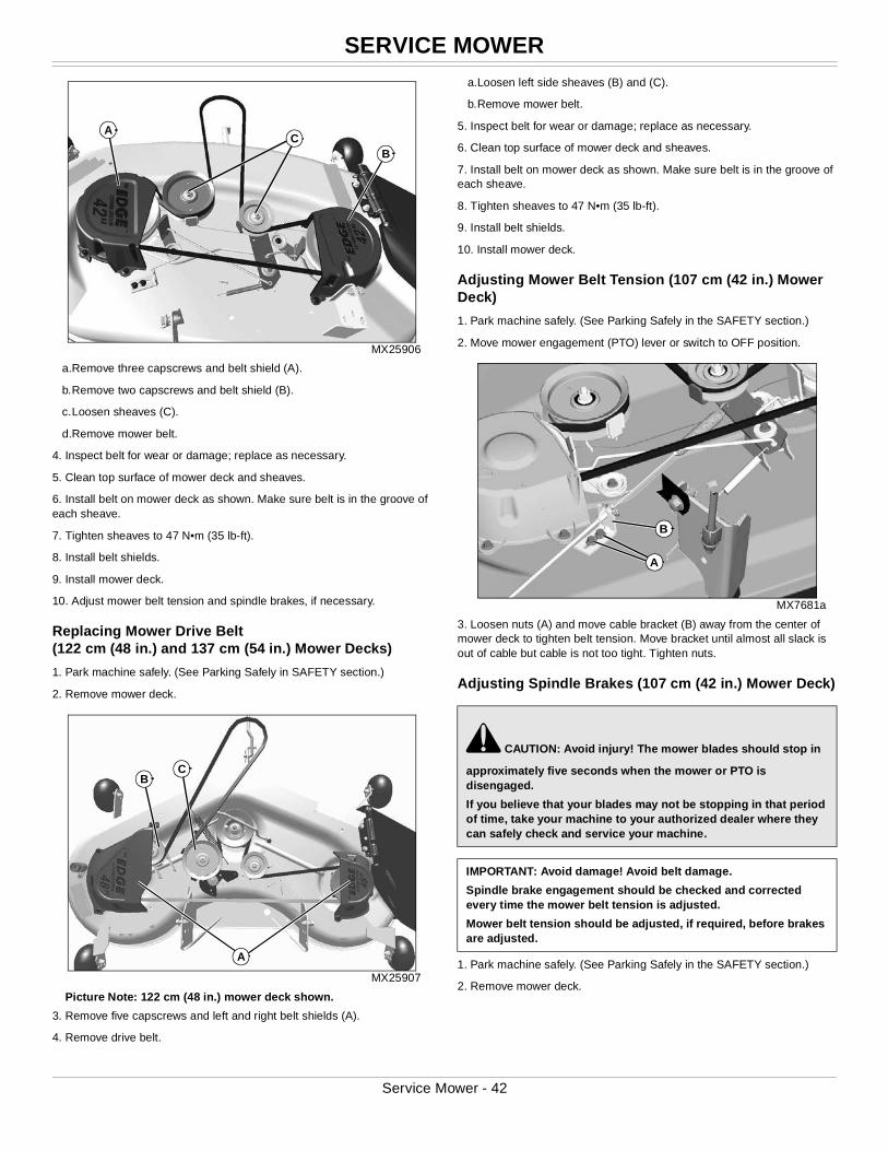
SERVICE MOWER
MX25906
a.Remove three capscrews and belt shield (A).
b.Remove two capscrews and belt shield (B).
c.Loosen sheaves (C).
d.Remove mower belt.
4. Inspect belt for wear or damage; replace as necessary.
5. Clean top surface of mower deck and sheaves.
6. Install belt on mower deck as shown. Make sure belt is in the groove of each sheave.
7. Tighten sheaves to 47 N•m (35 lb-ft).
8. Install belt shields.
9. Install mower deck.
10. Adjust mower belt tension and spindle brakes, if necessary.
Replacing Mower Drive Belt(122 cm (48 in.) and 137 cm (54 in.) Mower Decks)
1. Park machine safely. (See Parking Safely in SAFETY section.)
2. Remove mower deck.
MX25907
Picture Note: 122 cm (48 in.) mower deck shown.
3. Remove five capscrews and left and right belt shields (A).
4. Remove drive belt.
a.Loosen left side sheaves (B) and (C).
b.Remove mower belt.
5. Inspect belt for wear or damage; replace as necessary.
6. Clean top surface of mower deck and sheaves.
7. Install belt on mower deck as shown. Make sure belt is in the groove of each sheave.
8. Tighten sheaves to 47 N•m (35 lb-ft).
9. Install belt shields.
10. Install mower deck.
Adjusting Mower Belt Tension (107 cm (42 in.) Mower Deck)
1. Park machine safely. (See Parking Safely in the SAFETY section.)
2. Move mower engagement (PTO) lever or switch to OFF position.
MX7681a
3. Loosen nuts (A) and move cable bracket (B) away from the center of mower deck to tighten belt tension. Move bracket until almost all slack is out of cable but cable is not too tight. Tighten nuts.
Adjusting Spindle Brakes (107 cm (42 in.) Mower Deck)
1. Park machine safely. (See Parking Safely in the SAFETY section.)
2. Remove mower deck.
A
BC
A
BC
c CAUTION: Avoid injury! The mower blades should stop in
approximately five seconds when the mower or PTO is disengaged.
If you believe that your blades may not be stopping in that period of time, take your machine to your authorized dealer where they can safely check and service your machine.
IMPORTANT: Avoid damage! Avoid belt damage.
Spindle brake engagement should be checked and corrected every time the mower belt tension is adjusted.
Mower belt tension should be adjusted, if required, before brakes are adjusted.
B
A
Service Mower - 42
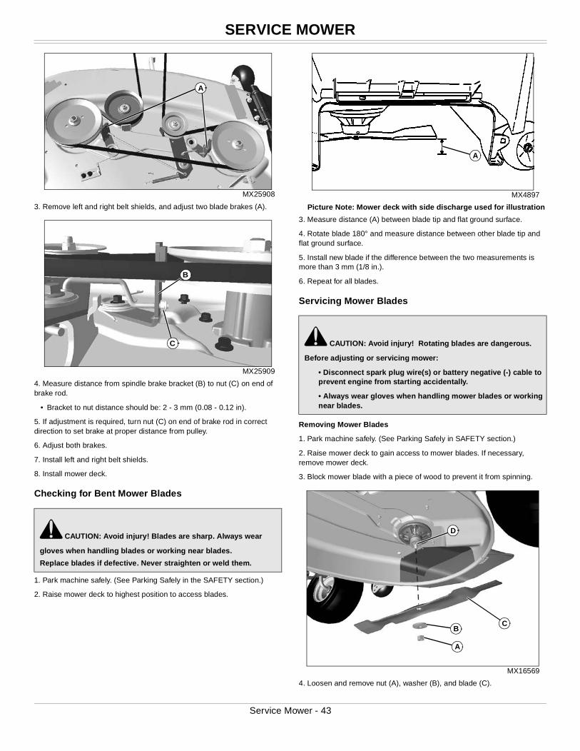
SERVICE MOWER
MX25908
3. Remove left and right belt shields, and adjust two blade brakes (A).
MX25909
4. Measure distance from spindle brake bracket (B) to nut (C) on end of brake rod.
• Bracket to nut distance should be: 2 - 3 mm (0.08 - 0.12 in).
5. If adjustment is required, turn nut (C) on end of brake rod in correct direction to set brake at proper distance from pulley.
6. Adjust both brakes.
7. Install left and right belt shields.
8. Install mower deck.
Checking for Bent Mower Blades
1. Park machine safely. (See Parking Safely in the SAFETY section.)
2. Raise mower deck to highest position to access blades.
MX4897
Picture Note: Mower deck with side discharge used for illustration
3. Measure distance (A) between blade tip and flat ground surface.
4. Rotate blade 180° and measure distance between other blade tip and flat ground surface.
5. Install new blade if the difference between the two measurements is more than 3 mm (1/8 in.).
6. Repeat for all blades.
Servicing Mower Blades
Removing Mower Blades
1. Park machine safely. (See Parking Safely in SAFETY section.)
2. Raise mower deck to gain access to mower blades. If necessary, remove mower deck.
3. Block mower blade with a piece of wood to prevent it from spinning.
MX16569
4. Loosen and remove nut (A), washer (B), and blade (C).
c CAUTION: Avoid injury! Blades are sharp. Always wear
gloves when handling blades or working near blades.
Replace blades if defective. Never straighten or weld them.
A
C
B
c CAUTION: Avoid injury! Rotating blades are dangerous.
Before adjusting or servicing mower:
• Disconnect spark plug wire(s) or battery negative (-) cable to prevent engine from starting accidentally.
• Always wear gloves when handling mower blades or working near blades.
A
CB
D
A
Service Mower - 43
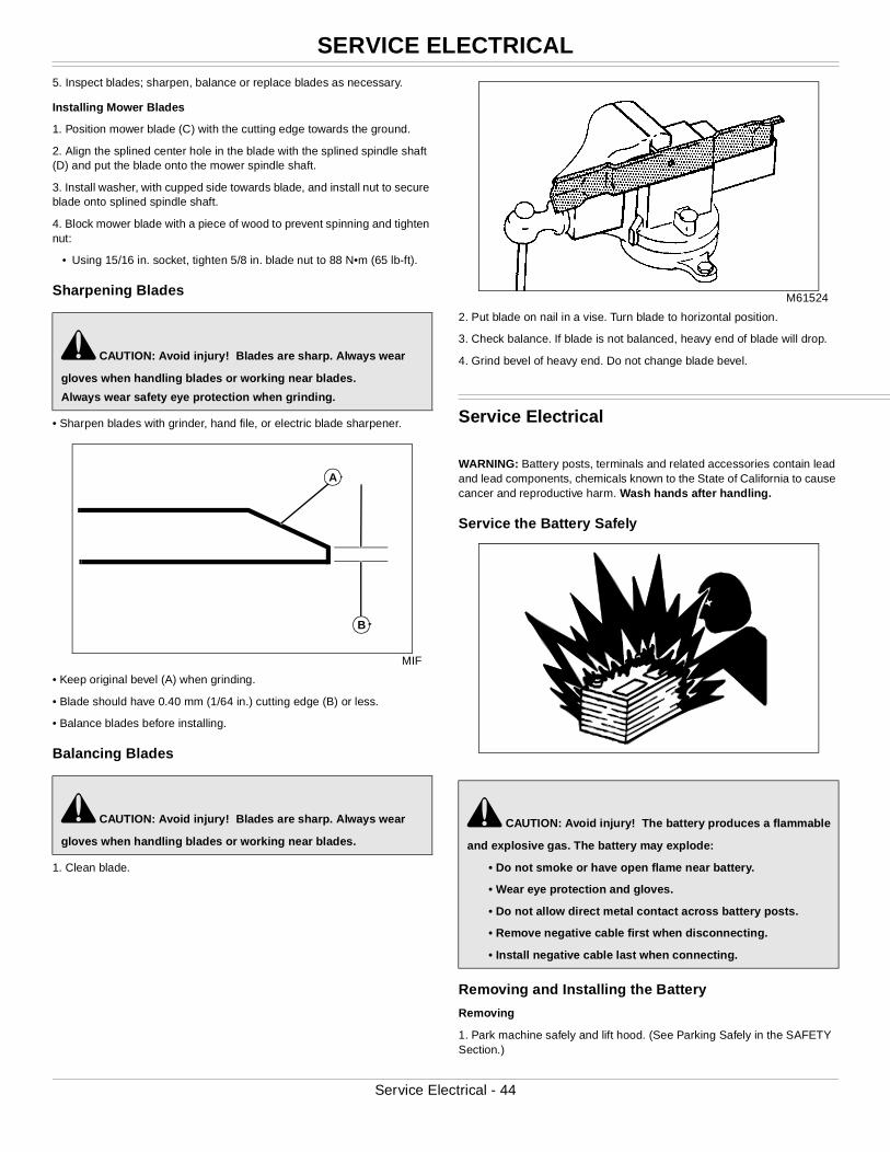
SERVICE ELECTRICAL
5. Inspect blades; sharpen, balance or replace blades as necessary.Installing Mower Blades
1. Position mower blade (C) with the cutting edge towards the ground.
2. Align the splined center hole in the blade with the splined spindle shaft (D) and put the blade onto the mower spindle shaft.
3. Install washer, with cupped side towards blade, and install nut to secure blade onto splined spindle shaft.
4. Block mower blade with a piece of wood to prevent spinning and tighten nut:
• Using 15/16 in. socket, tighten 5/8 in. blade nut to 88 N•m (65 lb-ft).
Sharpening Blades
• Sharpen blades with grinder, hand file, or electric blade sharpener.
MIF
• Keep original bevel (A) when grinding.
• Blade should have 0.40 mm (1/64 in.) cutting edge (B) or less.
• Balance blades before installing.
Balancing Blades
1. Clean blade.
M61524
2. Put blade on nail in a vise. Turn blade to horizontal position.
3. Check balance. If blade is not balanced, heavy end of blade will drop.
4. Grind bevel of heavy end. Do not change blade bevel.
Service Electrical
WARNING: Battery posts, terminals and related accessories contain lead and lead components, chemicals known to the State of California to cause cancer and reproductive harm. Wash hands after handling.
Service the Battery Safely
Removing and Installing the Battery
Removing
1. Park machine safely and lift hood. (See Parking Safely in the SAFETY Section.)
c CAUTION: Avoid injury! Blades are sharp. Always wear
gloves when handling blades or working near blades.
Always wear safety eye protection when grinding.
c CAUTION: Avoid injury! Blades are sharp. Always wear
gloves when handling blades or working near blades.
A
B
c CAUTION: Avoid injury! The battery produces a flammable
and explosive gas. The battery may explode:
• Do not smoke or have open flame near battery.
• Wear eye protection and gloves.
• Do not allow direct metal contact across battery posts.
• Remove negative cable first when disconnecting.
• Install negative cable last when connecting.
Service Electrical - 44
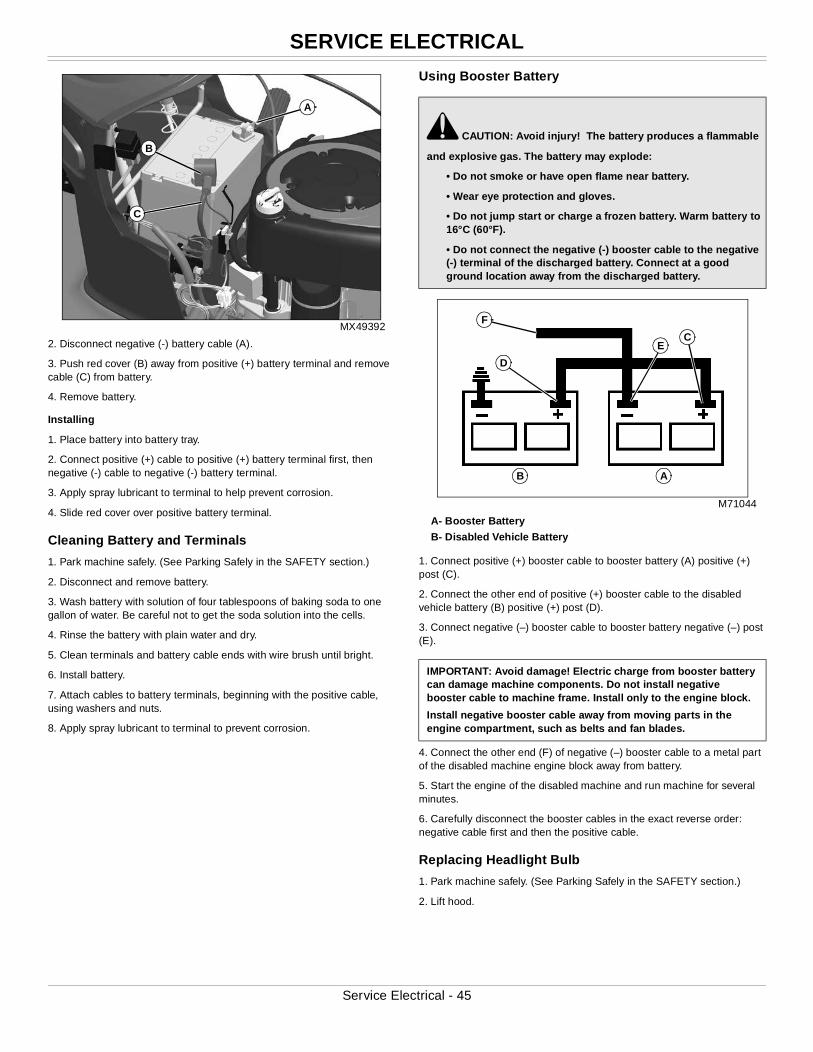
SERVICE ELECTRICAL
MX49392
2. Disconnect negative (-) battery cable (A).
3. Push red cover (B) away from positive (+) battery terminal and remove cable (C) from battery.
4. Remove battery.
Installing
1. Place battery into battery tray.
2. Connect positive (+) cable to positive (+) battery terminal first, then negative (-) cable to negative (-) battery terminal.
3. Apply spray lubricant to terminal to help prevent corrosion.
4. Slide red cover over positive battery terminal.
Cleaning Battery and Terminals
1. Park machine safely. (See Parking Safely in the SAFETY section.)
2. Disconnect and remove battery.
3. Wash battery with solution of four tablespoons of baking soda to one gallon of water. Be careful not to get the soda solution into the cells.
4. Rinse the battery with plain water and dry.
5. Clean terminals and battery cable ends with wire brush until bright.
6. Install battery.
7. Attach cables to battery terminals, beginning with the positive cable, using washers and nuts.
8. Apply spray lubricant to terminal to prevent corrosion.
Using Booster Battery
M71044
A- Booster Battery
B- Disabled Vehicle Battery
1. Connect positive (+) booster cable to booster battery (A) positive (+) post (C).
2. Connect the other end of positive (+) booster cable to the disabled vehicle battery (B) positive (+) post (D).
3. Connect negative (–) booster cable to booster battery negative (–) post (E).
4. Connect the other end (F) of negative (–) booster cable to a metal part of the disabled machine engine block away from battery.
5. Start the engine of the disabled machine and run machine for several minutes.
6. Carefully disconnect the booster cables in the exact reverse order: negative cable first and then the positive cable.
Replacing Headlight Bulb
1. Park machine safely. (See Parking Safely in the SAFETY section.)
2. Lift hood.
C
A
Bc CAUTION: Avoid injury! The battery produces a flammable
and explosive gas. The battery may explode:
• Do not smoke or have open flame near battery.
• Wear eye protection and gloves.
• Do not jump start or charge a frozen battery. Warm battery to 16°C (60°F).
• Do not connect the negative (-) booster cable to the negative (-) terminal of the discharged battery. Connect at a good ground location away from the discharged battery.
IMPORTANT: Avoid damage! Electric charge from booster battery can damage machine components. Do not install negative booster cable to machine frame. Install only to the engine block.
Install negative booster cable away from moving parts in the engine compartment, such as belts and fan blades.
B A
EC
D
F
Service Electrical - 45
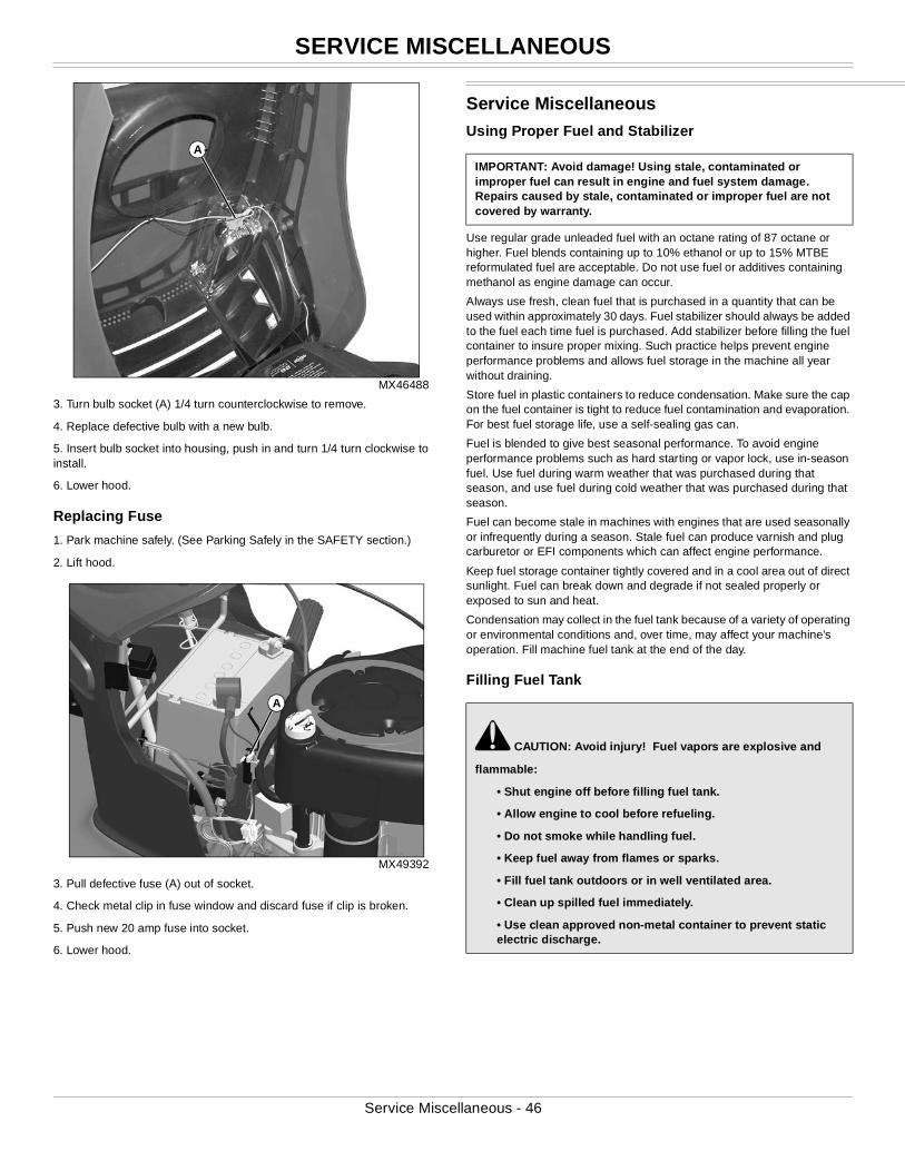
SERVICE MISCELLANEOUS
MX46488
3. Turn bulb socket (A) 1/4 turn counterclockwise to remove.
4. Replace defective bulb with a new bulb.
5. Insert bulb socket into housing, push in and turn 1/4 turn clockwise to install.
6. Lower hood.
Replacing Fuse
1. Park machine safely. (See Parking Safely in the SAFETY section.)
2. Lift hood.
MX49392
3. Pull defective fuse (A) out of socket.
4. Check metal clip in fuse window and discard fuse if clip is broken.
5. Push new 20 amp fuse into socket.
6. Lower hood.
Service MiscellaneousUsing Proper Fuel and Stabilizer
Use regular grade unleaded fuel with an octane rating of 87 octane or higher. Fuel blends containing up to 10% ethanol or up to 15% MTBE reformulated fuel are acceptable. Do not use fuel or additives containing methanol as engine damage can occur.
Always use fresh, clean fuel that is purchased in a quantity that can be used within approximately 30 days. Fuel stabilizer should always be added to the fuel each time fuel is purchased. Add stabilizer before filling the fuel container to insure proper mixing. Such practice helps prevent engine performance problems and allows fuel storage in the machine all year without draining.
Store fuel in plastic containers to reduce condensation. Make sure the cap on the fuel container is tight to reduce fuel contamination and evaporation. For best fuel storage life, use a self-sealing gas can.
Fuel is blended to give best seasonal performance. To avoid engine performance problems such as hard starting or vapor lock, use in-season fuel. Use fuel during warm weather that was purchased during that season, and use fuel during cold weather that was purchased during that season.
Fuel can become stale in machines with engines that are used seasonally or infrequently during a season. Stale fuel can produce varnish and plug carburetor or EFI components which can affect engine performance.
Keep fuel storage container tightly covered and in a cool area out of direct sunlight. Fuel can break down and degrade if not sealed properly or exposed to sun and heat.
Condensation may collect in the fuel tank because of a variety of operating or environmental conditions and, over time, may affect your machine’s operation. Fill machine fuel tank at the end of the day.
Filling Fuel Tank
A
A
IMPORTANT: Avoid damage! Using stale, contaminated or improper fuel can result in engine and fuel system damage. Repairs caused by stale, contaminated or improper fuel are not covered by warranty.
c CAUTION: Avoid injury! Fuel vapors are explosive and
flammable:
• Shut engine off before filling fuel tank.
• Allow engine to cool before refueling.
• Do not smoke while handling fuel.
• Keep fuel away from flames or sparks.
• Fill fuel tank outdoors or in well ventilated area.
• Clean up spilled fuel immediately.
• Use clean approved non-metal container to prevent static electric discharge.
Service Miscellaneous - 46
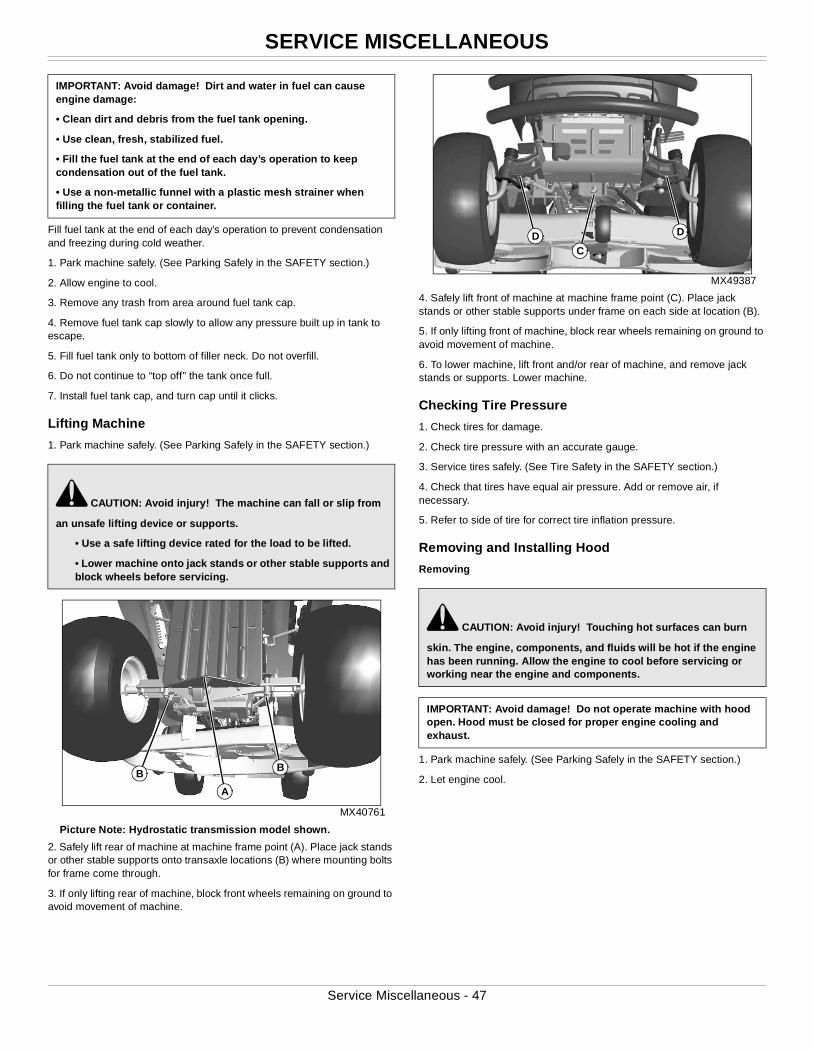
SERVICE MISCELLANEOUS
Fill fuel tank at the end of each day’s operation to prevent condensation and freezing during cold weather.
1. Park machine safely. (See Parking Safely in the SAFETY section.)
2. Allow engine to cool.
3. Remove any trash from area around fuel tank cap.
4. Remove fuel tank cap slowly to allow any pressure built up in tank to escape.
5. Fill fuel tank only to bottom of filler neck. Do not overfill.
6. Do not continue to “top off” the tank once full.
7. Install fuel tank cap, and turn cap until it clicks.
Lifting Machine
1. Park machine safely. (See Parking Safely in the SAFETY section.)
MX40761
Picture Note: Hydrostatic transmission model shown.
2. Safely lift rear of machine at machine frame point (A). Place jack stands or other stable supports onto transaxle locations (B) where mounting bolts for frame come through.
3. If only lifting rear of machine, block front wheels remaining on ground to avoid movement of machine.
MX49387
4. Safely lift front of machine at machine frame point (C). Place jack stands or other stable supports under frame on each side at location (B).
5. If only lifting front of machine, block rear wheels remaining on ground to avoid movement of machine.
6. To lower machine, lift front and/or rear of machine, and remove jack stands or supports. Lower machine.
Checking Tire Pressure
1. Check tires for damage.
2. Check tire pressure with an accurate gauge.
3. Service tires safely. (See Tire Safety in the SAFETY section.)
4. Check that tires have equal air pressure. Add or remove air, if necessary.
5. Refer to side of tire for correct tire inflation pressure.
Removing and Installing Hood
Removing
1. Park machine safely. (See Parking Safely in the SAFETY section.)
2. Let engine cool.
IMPORTANT: Avoid damage! Dirt and water in fuel can cause engine damage:
• Clean dirt and debris from the fuel tank opening.
• Use clean, fresh, stabilized fuel.
• Fill the fuel tank at the end of each day’s operation to keep condensation out of the fuel tank.
• Use a non-metallic funnel with a plastic mesh strainer when filling the fuel tank or container.
c CAUTION: Avoid injury! The machine can fall or slip from
an unsafe lifting device or supports.
• Use a safe lifting device rated for the load to be lifted.
• Lower machine onto jack stands or other stable supports and block wheels before servicing.
BB
A
c CAUTION: Avoid injury! Touching hot surfaces can burn
skin. The engine, components, and fluids will be hot if the engine has been running. Allow the engine to cool before servicing or working near the engine and components.
IMPORTANT: Avoid damage! Do not operate machine with hood open. Hood must be closed for proper engine cooling and exhaust.
DDC
Service Miscellaneous - 47
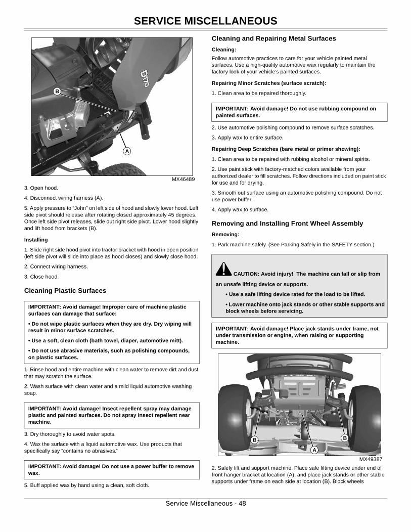
SERVICE MISCELLANEOUS
MX46489
3. Open hood.
4. Disconnect wiring harness (A).
5. Apply pressure to “John” on left side of hood and slowly lower hood. Left side pivot should release after rotating closed approximately 45 degrees. Once left side pivot releases, slide out right side pivot. Lower hood slightly and lift hood from brackets (B).
Installing
1. Slide right side hood pivot into tractor bracket with hood in open position (left side pivot will slide into place as hood closes) and slowly close hood.
2. Connect wiring harness.
3. Close hood.
Cleaning Plastic Surfaces
1. Rinse hood and entire machine with clean water to remove dirt and dust that may scratch the surface.
2. Wash surface with clean water and a mild liquid automotive washing soap.
3. Dry thoroughly to avoid water spots.
4. Wax the surface with a liquid automotive wax. Use products that specifically say “contains no abrasives.”
5. Buff applied wax by hand using a clean, soft cloth.
Cleaning and Repairing Metal Surfaces
Cleaning:
Follow automotive practices to care for your vehicle painted metal surfaces. Use a high-quality automotive wax regularly to maintain the factory look of your vehicle’s painted surfaces.
Repairing Minor Scratches (surface scratch):
1. Clean area to be repaired thoroughly.
2. Use automotive polishing compound to remove surface scratches.
3. Apply wax to entire surface.
Repairing Deep Scratches (bare metal or primer showing):
1. Clean area to be repaired with rubbing alcohol or mineral spirits.
2. Use paint stick with factory-matched colors available from your authorized dealer to fill scratches. Follow directions included on paint stick for use and for drying.
3. Smooth out surface using an automotive polishing compound. Do not use power buffer.
4. Apply wax to surface.
Removing and Installing Front Wheel Assembly
Removing:
1. Park machine safely. (See Parking Safely in the SAFETY section.)
MX49387
2. Safely lift and support machine. Place safe lifting device under end of front hanger bracket at location (A), and place jack stands or other stable supports under frame on each side at location (B). Block wheels
IMPORTANT: Avoid damage! Improper care of machine plastic surfaces can damage that surface:
• Do not wipe plastic surfaces when they are dry. Dry wiping will result in minor surface scratches.
• Use a soft, clean cloth (bath towel, diaper, automotive mitt).
• Do not use abrasive materials, such as polishing compounds, on plastic surfaces.
IMPORTANT: Avoid damage! Insect repellent spray may damage plastic and painted surfaces. Do not spray insect repellent near machine.
IMPORTANT: Avoid damage! Do not use a power buffer to remove wax.
A
B
IMPORTANT: Avoid damage! Do not use rubbing compound on painted surfaces.
c CAUTION: Avoid injury! The machine can fall or slip from
an unsafe lifting device or supports.
• Use a safe lifting device rated for the load to be lifted.
• Lower machine onto jack stands or other stable supports and block wheels before servicing.
IMPORTANT: Avoid damage! Place jack stands under frame, not under transmission or engine, when raising or supporting machine.
A
B B
Service Miscellaneous - 48
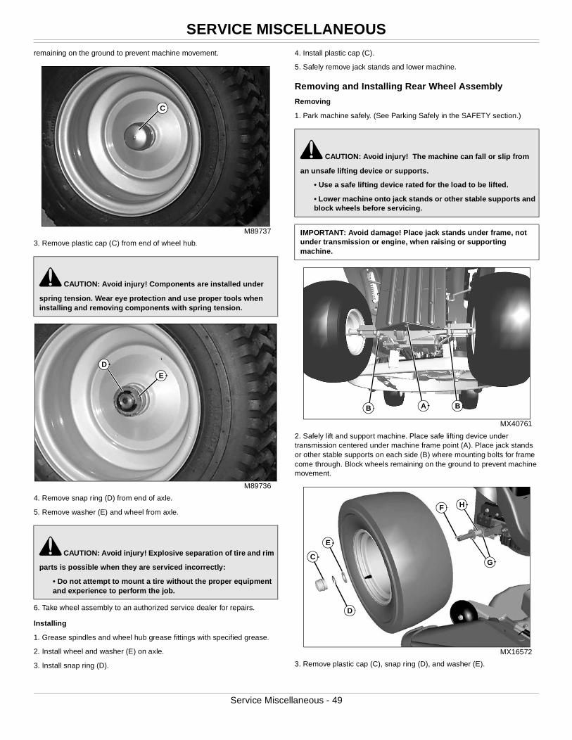
SERVICE MISCELLANEOUS
remaining on the ground to prevent machine movement.M89737
3. Remove plastic cap (C) from end of wheel hub.
M89736
4. Remove snap ring (D) from end of axle.
5. Remove washer (E) and wheel from axle.
6. Take wheel assembly to an authorized service dealer for repairs.
Installing
1. Grease spindles and wheel hub grease fittings with specified grease.
2. Install wheel and washer (E) on axle.
3. Install snap ring (D).
4. Install plastic cap (C).
5. Safely remove jack stands and lower machine.
Removing and Installing Rear Wheel Assembly
Removing
1. Park machine safely. (See Parking Safely in the SAFETY section.)
MX40761
2. Safely lift and support machine. Place safe lifting device under transmission centered under machine frame point (A). Place jack stands or other stable supports on each side (B) where mounting bolts for frame come through. Block wheels remaining on the ground to prevent machine movement.
MX16572
3. Remove plastic cap (C), snap ring (D), and washer (E).
c CAUTION: Avoid injury! Components are installed under
spring tension. Wear eye protection and use proper tools when installing and removing components with spring tension.
c CAUTION: Avoid injury! Explosive separation of tire and rim
parts is possible when they are serviced incorrectly:
• Do not attempt to mount a tire without the proper equipment and experience to perform the job.
C
D
E
c CAUTION: Avoid injury! The machine can fall or slip from
an unsafe lifting device or supports.
• Use a safe lifting device rated for the load to be lifted.
• Lower machine onto jack stands or other stable supports and block wheels before servicing.
IMPORTANT: Avoid damage! Place jack stands under frame, not under transmission or engine, when raising or supporting machine.
AB B
F H
C
E
D
G
Service Miscellaneous - 49
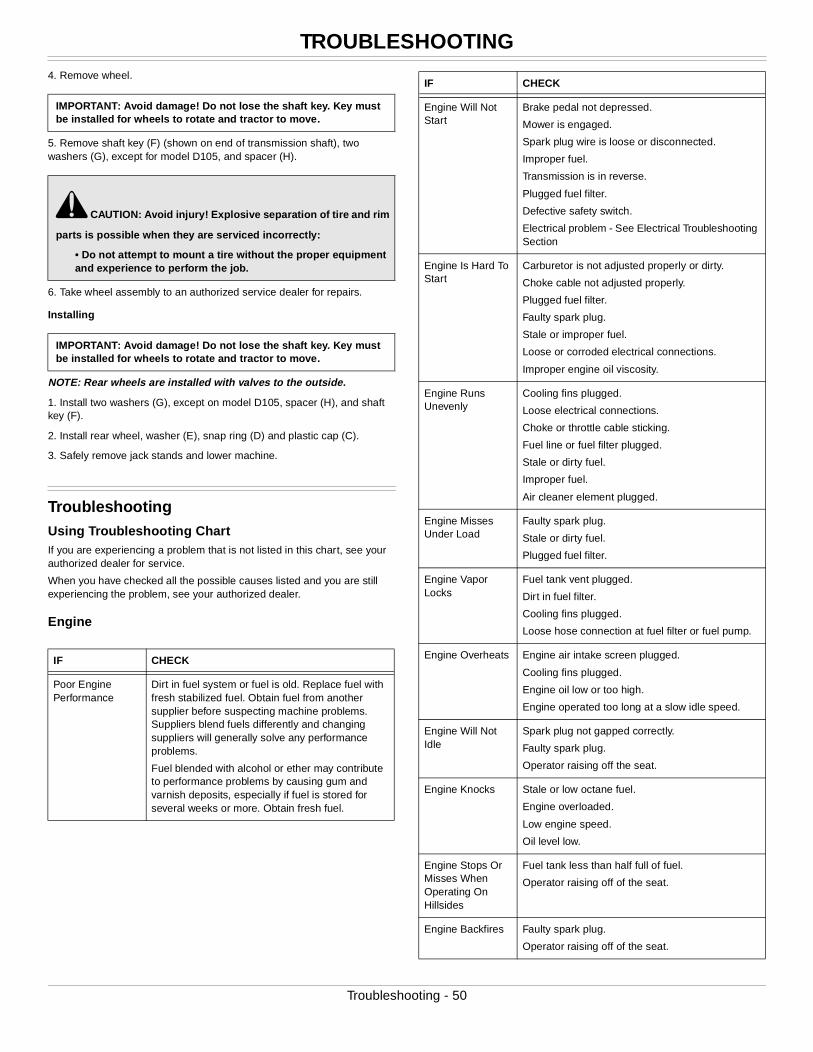
TROUBLESHOOTING
4. Remove wheel.5. Remove shaft key (F) (shown on end of transmission shaft), two washers (G), except for model D105, and spacer (H).
6. Take wheel assembly to an authorized service dealer for repairs.
Installing
NOTE: Rear wheels are installed with valves to the outside.
1. Install two washers (G), except on model D105, spacer (H), and shaft key (F).
2. Install rear wheel, washer (E), snap ring (D) and plastic cap (C).
3. Safely remove jack stands and lower machine.
TroubleshootingUsing Troubleshooting ChartIf you are experiencing a problem that is not listed in this chart, see your authorized dealer for service.
When you have checked all the possible causes listed and you are still experiencing the problem, see your authorized dealer.
Engine
IMPORTANT: Avoid damage! Do not lose the shaft key. Key must be installed for wheels to rotate and tractor to move.
c CAUTION: Avoid injury! Explosive separation of tire and rim
parts is possible when they are serviced incorrectly:
• Do not attempt to mount a tire without the proper equipment and experience to perform the job.
IMPORTANT: Avoid damage! Do not lose the shaft key. Key must be installed for wheels to rotate and tractor to move.
IF CHECK
Poor Engine Performance
Dirt in fuel system or fuel is old. Replace fuel with fresh stabilized fuel. Obtain fuel from another supplier before suspecting machine problems. Suppliers blend fuels differently and changing suppliers will generally solve any performance problems.
Fuel blended with alcohol or ether may contribute to performance problems by causing gum and varnish deposits, especially if fuel is stored for several weeks or more. Obtain fresh fuel.
Engine Will Not Start
Brake pedal not depressed.
Mower is engaged.
Spark plug wire is loose or disconnected.
Improper fuel.
Transmission is in reverse.
Plugged fuel filter.
Defective safety switch.
Electrical problem - See Electrical Troubleshooting Section
Engine Is Hard To Start
Carburetor is not adjusted properly or dirty.
Choke cable not adjusted properly.
Plugged fuel filter.
Faulty spark plug.
Stale or improper fuel.
Loose or corroded electrical connections.
Improper engine oil viscosity.
Engine Runs Unevenly
Cooling fins plugged.
Loose electrical connections.
Choke or throttle cable sticking.
Fuel line or fuel filter plugged.
Stale or dirty fuel.
Improper fuel.
Air cleaner element plugged.
Engine Misses Under Load
Faulty spark plug.
Stale or dirty fuel.
Plugged fuel filter.
Engine Vapor Locks
Fuel tank vent plugged.
Dirt in fuel filter.
Cooling fins plugged.
Loose hose connection at fuel filter or fuel pump.
Engine Overheats Engine air intake screen plugged.
Cooling fins plugged.
Engine oil low or too high.
Engine operated too long at a slow idle speed.
Engine Will Not Idle
Spark plug not gapped correctly.
Faulty spark plug.
Operator raising off the seat.
Engine Knocks Stale or low octane fuel.
Engine overloaded.
Low engine speed.
Oil level low.
Engine Stops Or Misses When Operating On Hillsides
Fuel tank less than half full of fuel.
Operator raising off of the seat.
Engine Backfires Faulty spark plug.
Operator raising off of the seat.
IF CHECK
Troubleshooting - 50
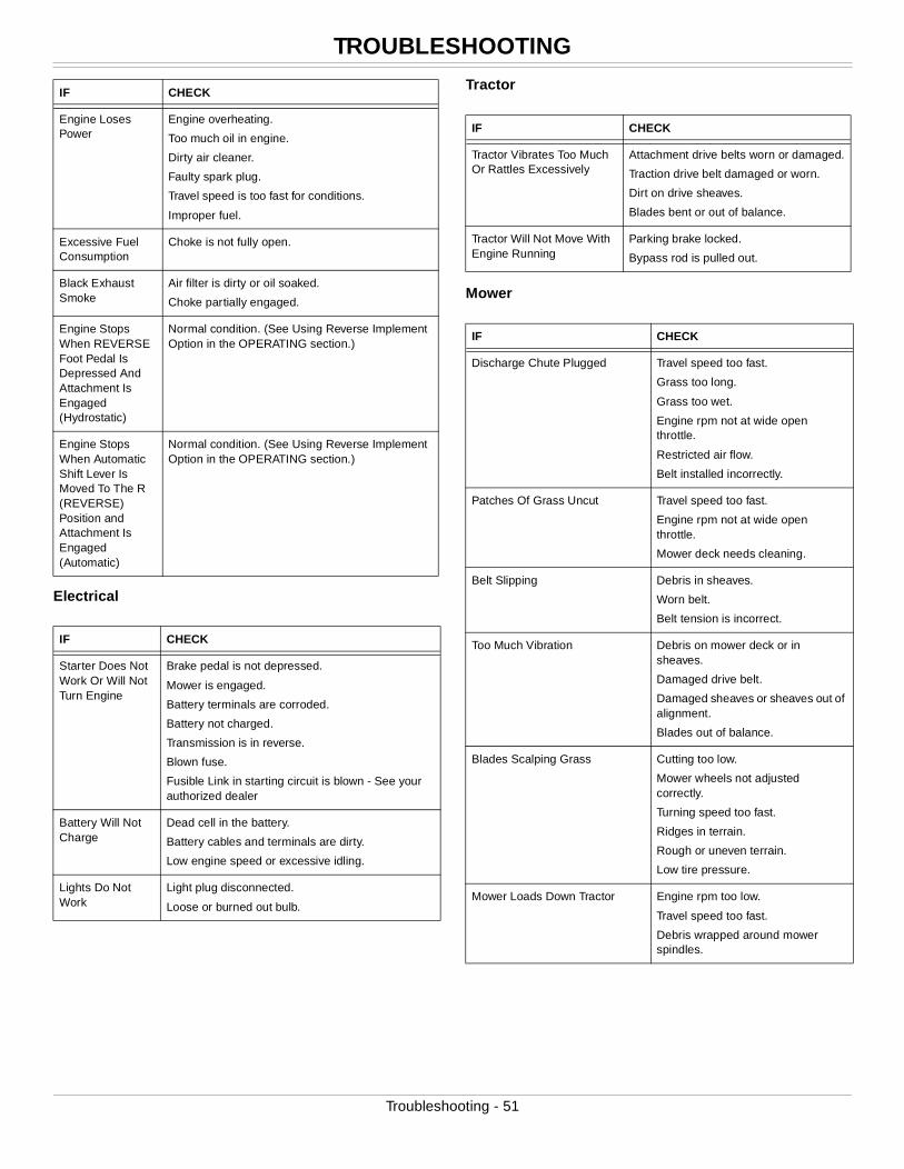
TROUBLESHOOTING
Electrical
Tractor
Mower
Engine Loses Power
Engine overheating.
Too much oil in engine.
Dirty air cleaner.
Faulty spark plug.
Travel speed is too fast for conditions.
Improper fuel.
Excessive Fuel Consumption
Choke is not fully open.
Black Exhaust Smoke
Air filter is dirty or oil soaked.
Choke partially engaged.
Engine Stops When REVERSE Foot Pedal Is Depressed And Attachment Is Engaged (Hydrostatic)
Normal condition. (See Using Reverse Implement Option in the OPERATING section.)
Engine Stops When Automatic Shift Lever Is Moved To The R (REVERSE) Position and Attachment Is Engaged (Automatic)
Normal condition. (See Using Reverse Implement Option in the OPERATING section.)
IF CHECK
Starter Does Not Work Or Will Not Turn Engine
Brake pedal is not depressed.
Mower is engaged.
Battery terminals are corroded.
Battery not charged.
Transmission is in reverse.
Blown fuse.
Fusible Link in starting circuit is blown - See your authorized dealer
Battery Will Not Charge
Dead cell in the battery.
Battery cables and terminals are dirty.
Low engine speed or excessive idling.
Lights Do Not Work
Light plug disconnected.
Loose or burned out bulb.
IF CHECK
IF CHECK
Tractor Vibrates Too Much Or Rattles Excessively
Attachment drive belts worn or damaged.
Traction drive belt damaged or worn.
Dirt on drive sheaves.
Blades bent or out of balance.
Tractor Will Not Move With Engine Running
Parking brake locked.
Bypass rod is pulled out.
IF CHECK
Discharge Chute Plugged Travel speed too fast.
Grass too long.
Grass too wet.
Engine rpm not at wide open throttle.
Restricted air flow.
Belt installed incorrectly.
Patches Of Grass Uncut Travel speed too fast.
Engine rpm not at wide open throttle.
Mower deck needs cleaning.
Belt Slipping Debris in sheaves.
Worn belt.
Belt tension is incorrect.
Too Much Vibration Debris on mower deck or in sheaves.
Damaged drive belt.
Damaged sheaves or sheaves out of alignment.
Blades out of balance.
Blades Scalping Grass Cutting too low.
Mower wheels not adjusted correctly.
Turning speed too fast.
Ridges in terrain.
Rough or uneven terrain.
Low tire pressure.
Mower Loads Down Tractor Engine rpm too low.
Travel speed too fast.
Debris wrapped around mower spindles.
Troubleshooting - 51
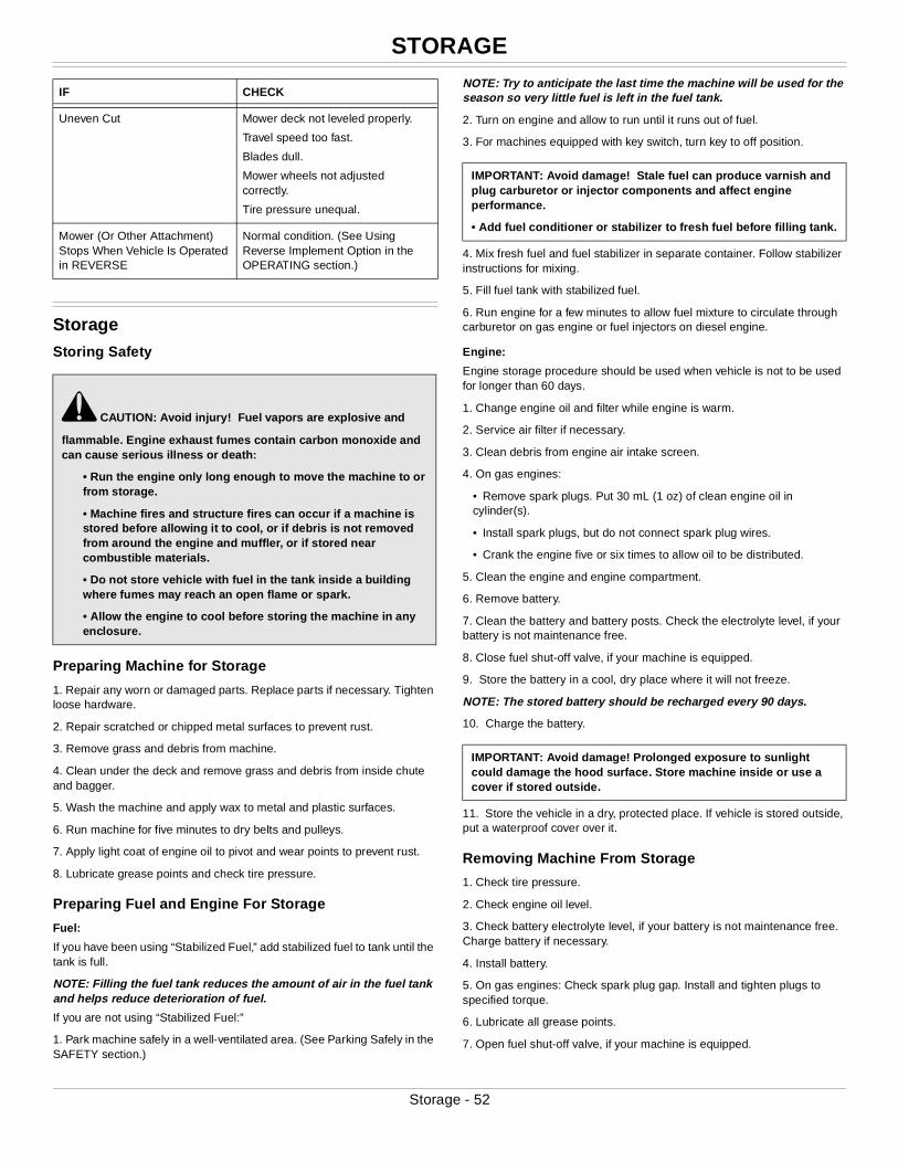
STORAGE
StorageStoring Safety
Preparing Machine for Storage
1. Repair any worn or damaged parts. Replace parts if necessary. Tighten loose hardware.
2. Repair scratched or chipped metal surfaces to prevent rust.
3. Remove grass and debris from machine.
4. Clean under the deck and remove grass and debris from inside chute and bagger.
5. Wash the machine and apply wax to metal and plastic surfaces.
6. Run machine for five minutes to dry belts and pulleys.
7. Apply light coat of engine oil to pivot and wear points to prevent rust.
8. Lubricate grease points and check tire pressure.
Preparing Fuel and Engine For Storage
Fuel:
If you have been using “Stabilized Fuel,” add stabilized fuel to tank until the tank is full.
NOTE: Filling the fuel tank reduces the amount of air in the fuel tank and helps reduce deterioration of fuel.
If you are not using “Stabilized Fuel:”
1. Park machine safely in a well-ventilated area. (See Parking Safely in the SAFETY section.)
NOTE: Try to anticipate the last time the machine will be used for the season so very little fuel is left in the fuel tank.
2. Turn on engine and allow to run until it runs out of fuel.
3. For machines equipped with key switch, turn key to off position.
4. Mix fresh fuel and fuel stabilizer in separate container. Follow stabilizer instructions for mixing.
5. Fill fuel tank with stabilized fuel.
6. Run engine for a few minutes to allow fuel mixture to circulate through carburetor on gas engine or fuel injectors on diesel engine.
Engine:
Engine storage procedure should be used when vehicle is not to be used for longer than 60 days.
1. Change engine oil and filter while engine is warm.
2. Service air filter if necessary.
3. Clean debris from engine air intake screen.
4. On gas engines:
• Remove spark plugs. Put 30 mL (1 oz) of clean engine oil in cylinder(s).
• Install spark plugs, but do not connect spark plug wires.
• Crank the engine five or six times to allow oil to be distributed.
5. Clean the engine and engine compartment.
6. Remove battery.
7. Clean the battery and battery posts. Check the electrolyte level, if your battery is not maintenance free.
8. Close fuel shut-off valve, if your machine is equipped.
9. Store the battery in a cool, dry place where it will not freeze.
NOTE: The stored battery should be recharged every 90 days.
10. Charge the battery.
11. Store the vehicle in a dry, protected place. If vehicle is stored outside, put a waterproof cover over it.
Removing Machine From Storage
1. Check tire pressure.
2. Check engine oil level.
3. Check battery electrolyte level, if your battery is not maintenance free. Charge battery if necessary.
4. Install battery.
5. On gas engines: Check spark plug gap. Install and tighten plugs to specified torque.
6. Lubricate all grease points.
7. Open fuel shut-off valve, if your machine is equipped.
Uneven Cut Mower deck not leveled properly.
Travel speed too fast.
Blades dull.
Mower wheels not adjusted correctly.
Tire pressure unequal.
Mower (Or Other Attachment) Stops When Vehicle Is Operated in REVERSE
Normal condition. (See Using Reverse Implement Option in the OPERATING section.)
c CAUTION: Avoid injury! Fuel vapors are explosive and
flammable. Engine exhaust fumes contain carbon monoxide and can cause serious illness or death:
• Run the engine only long enough to move the machine to or from storage.
• Machine fires and structure fires can occur if a machine is stored before allowing it to cool, or if debris is not removed from around the engine and muffler, or if stored near combustible materials.
• Do not store vehicle with fuel in the tank inside a building where fumes may reach an open flame or spark.
• Allow the engine to cool before storing the machine in any enclosure.
IF CHECK
IMPORTANT: Avoid damage! Stale fuel can produce varnish and plug carburetor or injector components and affect engine performance.
• Add fuel conditioner or stabilizer to fresh fuel before filling tank.
IMPORTANT: Avoid damage! Prolonged exposure to sunlight could damage the hood surface. Store machine inside or use a cover if stored outside.
Storage - 52
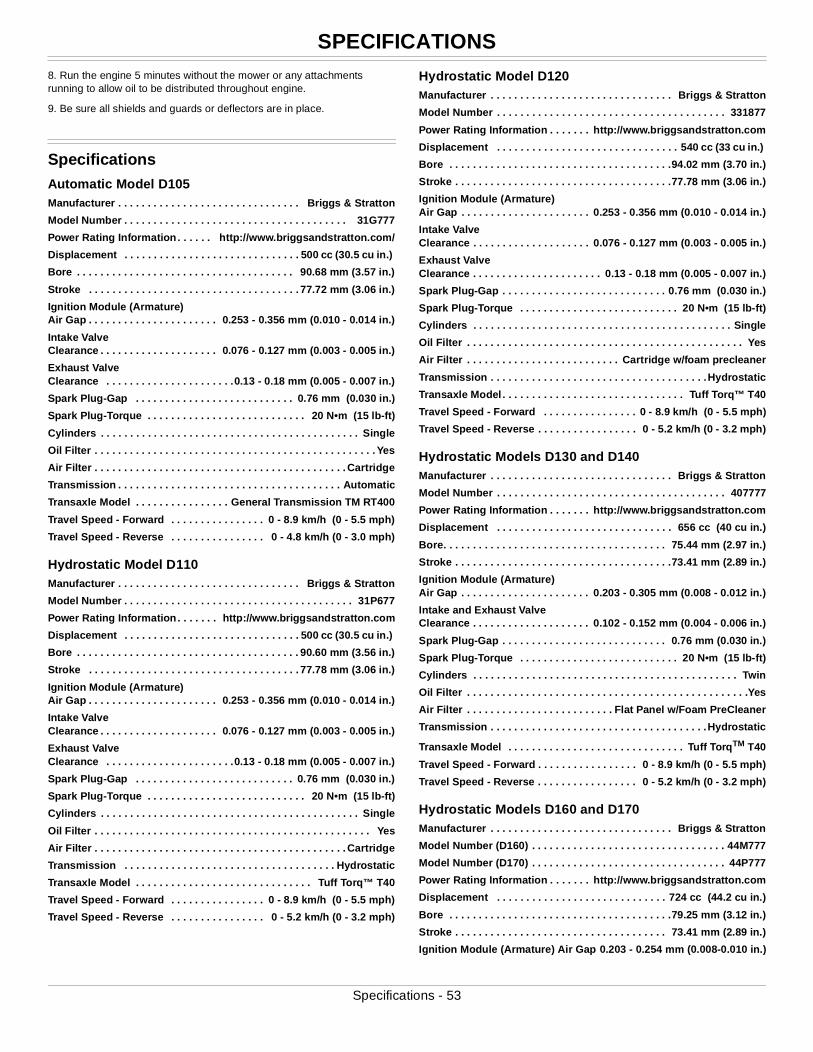
SPECIFICATIONS
8. Run the engine 5 minutes without the mower or any attachments running to allow oil to be distributed throughout engine.9. Be sure all shields and guards or deflectors are in place.
SpecificationsAutomatic Model D105Manufacturer . . . . . . . . . . . . . . . . . . . . . . . . . . . . . . . Briggs & Stratton
Model Number . . . . . . . . . . . . . . . . . . . . . . . . . . . . . . . . . . . . . . 31G777
Power Rating Information. . . . . . http://www.briggsandstratton.com/
Displacement . . . . . . . . . . . . . . . . . . . . . . . . . . . . . . 500 cc (30.5 cu in.)
Bore . . . . . . . . . . . . . . . . . . . . . . . . . . . . . . . . . . . . . 90.68 mm (3.57 in.)
Stroke . . . . . . . . . . . . . . . . . . . . . . . . . . . . . . . . . . . . 77.72 mm (3.06 in.)
Ignition Module (Armature) Air Gap . . . . . . . . . . . . . . . . . . . . . . 0.253 - 0.356 mm (0.010 - 0.014 in.)
Intake Valve Clearance . . . . . . . . . . . . . . . . . . . . 0.076 - 0.127 mm (0.003 - 0.005 in.)
Exhaust Valve Clearance . . . . . . . . . . . . . . . . . . . . . .0.13 - 0.18 mm (0.005 - 0.007 in.)
Spark Plug-Gap . . . . . . . . . . . . . . . . . . . . . . . . . . . 0.76 mm (0.030 in.)
Spark Plug-Torque . . . . . . . . . . . . . . . . . . . . . . . . . . . 20 N•m (15 lb-ft)
Cylinders . . . . . . . . . . . . . . . . . . . . . . . . . . . . . . . . . . . . . . . . . . . . Single
Oil Filter . . . . . . . . . . . . . . . . . . . . . . . . . . . . . . . . . . . . . . . . . . . . . . . . Yes
Air Filter . . . . . . . . . . . . . . . . . . . . . . . . . . . . . . . . . . . . . . . . . . . Cartridge
Transmission . . . . . . . . . . . . . . . . . . . . . . . . . . . . . . . . . . . . . . Automatic
Transaxle Model . . . . . . . . . . . . . . . . General Transmission TM RT400
Travel Speed - Forward . . . . . . . . . . . . . . . . 0 - 8.9 km/h (0 - 5.5 mph)
Travel Speed - Reverse . . . . . . . . . . . . . . . . 0 - 4.8 km/h (0 - 3.0 mph)
Hydrostatic Model D110Manufacturer . . . . . . . . . . . . . . . . . . . . . . . . . . . . . . . Briggs & Stratton
Model Number . . . . . . . . . . . . . . . . . . . . . . . . . . . . . . . . . . . . . . . 31P677
Power Rating Information. . . . . . . http://www.briggsandstratton.com
Displacement . . . . . . . . . . . . . . . . . . . . . . . . . . . . . . 500 cc (30.5 cu in.)
Bore . . . . . . . . . . . . . . . . . . . . . . . . . . . . . . . . . . . . . . 90.60 mm (3.56 in.)
Stroke . . . . . . . . . . . . . . . . . . . . . . . . . . . . . . . . . . . . 77.78 mm (3.06 in.)
Ignition Module (Armature) Air Gap . . . . . . . . . . . . . . . . . . . . . . 0.253 - 0.356 mm (0.010 - 0.014 in.)
Intake Valve Clearance . . . . . . . . . . . . . . . . . . . . 0.076 - 0.127 mm (0.003 - 0.005 in.)
Exhaust Valve Clearance . . . . . . . . . . . . . . . . . . . . . .0.13 - 0.18 mm (0.005 - 0.007 in.)
Spark Plug-Gap . . . . . . . . . . . . . . . . . . . . . . . . . . . 0.76 mm (0.030 in.)
Spark Plug-Torque . . . . . . . . . . . . . . . . . . . . . . . . . . . 20 N•m (15 lb-ft)
Cylinders . . . . . . . . . . . . . . . . . . . . . . . . . . . . . . . . . . . . . . . . . . . . Single
Oil Filter . . . . . . . . . . . . . . . . . . . . . . . . . . . . . . . . . . . . . . . . . . . . . . . Yes
Air Filter . . . . . . . . . . . . . . . . . . . . . . . . . . . . . . . . . . . . . . . . . . . Cartridge
Transmission . . . . . . . . . . . . . . . . . . . . . . . . . . . . . . . . . . . . Hydrostatic
Transaxle Model . . . . . . . . . . . . . . . . . . . . . . . . . . . . . . Tuff Torq™ T40
Travel Speed - Forward . . . . . . . . . . . . . . . . 0 - 8.9 km/h (0 - 5.5 mph)
Travel Speed - Reverse . . . . . . . . . . . . . . . . 0 - 5.2 km/h (0 - 3.2 mph)
Hydrostatic Model D120Manufacturer . . . . . . . . . . . . . . . . . . . . . . . . . . . . . . . Briggs & Stratton
Model Number . . . . . . . . . . . . . . . . . . . . . . . . . . . . . . . . . . . . . . . 331877
Power Rating Information . . . . . . . http://www.briggsandstratton.com
Displacement . . . . . . . . . . . . . . . . . . . . . . . . . . . . . . . 540 cc (33 cu in.)
Bore . . . . . . . . . . . . . . . . . . . . . . . . . . . . . . . . . . . . . .94.02 mm (3.70 in.)
Stroke . . . . . . . . . . . . . . . . . . . . . . . . . . . . . . . . . . . . .77.78 mm (3.06 in.)
Ignition Module (Armature) Air Gap . . . . . . . . . . . . . . . . . . . . . . 0.253 - 0.356 mm (0.010 - 0.014 in.)
Intake Valve Clearance . . . . . . . . . . . . . . . . . . . . 0.076 - 0.127 mm (0.003 - 0.005 in.)
Exhaust Valve Clearance . . . . . . . . . . . . . . . . . . . . . . 0.13 - 0.18 mm (0.005 - 0.007 in.)
Spark Plug-Gap . . . . . . . . . . . . . . . . . . . . . . . . . . . . 0.76 mm (0.030 in.)
Spark Plug-Torque . . . . . . . . . . . . . . . . . . . . . . . . . . . 20 N•m (15 lb-ft)
Cylinders . . . . . . . . . . . . . . . . . . . . . . . . . . . . . . . . . . . . . . . . . . . . Single
Oil Filter . . . . . . . . . . . . . . . . . . . . . . . . . . . . . . . . . . . . . . . . . . . . . . . Yes
Air Filter . . . . . . . . . . . . . . . . . . . . . . . . . . Cartridge w/foam precleaner
Transmission . . . . . . . . . . . . . . . . . . . . . . . . . . . . . . . . . . . . .Hydrostatic
Transaxle Model . . . . . . . . . . . . . . . . . . . . . . . . . . . . . . . Tuff Torq™ T40
Travel Speed - Forward . . . . . . . . . . . . . . . . 0 - 8.9 km/h (0 - 5.5 mph)
Travel Speed - Reverse . . . . . . . . . . . . . . . . . 0 - 5.2 km/h (0 - 3.2 mph)
Hydrostatic Models D130 and D140Manufacturer . . . . . . . . . . . . . . . . . . . . . . . . . . . . . . . Briggs & Stratton
Model Number . . . . . . . . . . . . . . . . . . . . . . . . . . . . . . . . . . . . . . . 407777
Power Rating Information . . . . . . . http://www.briggsandstratton.com
Displacement . . . . . . . . . . . . . . . . . . . . . . . . . . . . . . 656 cc (40 cu in.)
Bore. . . . . . . . . . . . . . . . . . . . . . . . . . . . . . . . . . . . . . 75.44 mm (2.97 in.)
Stroke . . . . . . . . . . . . . . . . . . . . . . . . . . . . . . . . . . . . .73.41 mm (2.89 in.)
Ignition Module (Armature) Air Gap . . . . . . . . . . . . . . . . . . . . . . 0.203 - 0.305 mm (0.008 - 0.012 in.)
Intake and Exhaust Valve Clearance . . . . . . . . . . . . . . . . . . . . 0.102 - 0.152 mm (0.004 - 0.006 in.)
Spark Plug-Gap . . . . . . . . . . . . . . . . . . . . . . . . . . . . 0.76 mm (0.030 in.)
Spark Plug-Torque . . . . . . . . . . . . . . . . . . . . . . . . . . . 20 N•m (15 lb-ft)
Cylinders . . . . . . . . . . . . . . . . . . . . . . . . . . . . . . . . . . . . . . . . . . . . . Twin
Oil Filter . . . . . . . . . . . . . . . . . . . . . . . . . . . . . . . . . . . . . . . . . . . . . . . .Yes
Air Filter . . . . . . . . . . . . . . . . . . . . . . . . . Flat Panel w/Foam PreCleaner
Transmission . . . . . . . . . . . . . . . . . . . . . . . . . . . . . . . . . . . . .Hydrostatic
Transaxle Model . . . . . . . . . . . . . . . . . . . . . . . . . . . . . . Tuff TorqTM T40
Travel Speed - Forward . . . . . . . . . . . . . . . . . 0 - 8.9 km/h (0 - 5.5 mph)
Travel Speed - Reverse . . . . . . . . . . . . . . . . . 0 - 5.2 km/h (0 - 3.2 mph)
Hydrostatic Models D160 and D170Manufacturer . . . . . . . . . . . . . . . . . . . . . . . . . . . . . . . Briggs & Stratton
Model Number (D160) . . . . . . . . . . . . . . . . . . . . . . . . . . . . . . . . . 44M777
Model Number (D170) . . . . . . . . . . . . . . . . . . . . . . . . . . . . . . . . . 44P777
Power Rating Information . . . . . . . http://www.briggsandstratton.com
Displacement . . . . . . . . . . . . . . . . . . . . . . . . . . . . . 724 cc (44.2 cu in.)
Bore . . . . . . . . . . . . . . . . . . . . . . . . . . . . . . . . . . . . . .79.25 mm (3.12 in.)
Stroke . . . . . . . . . . . . . . . . . . . . . . . . . . . . . . . . . . . . 73.41 mm (2.89 in.)
Ignition Module (Armature) Air Gap 0.203 - 0.254 mm (0.008-0.010 in.)
Specifications - 53
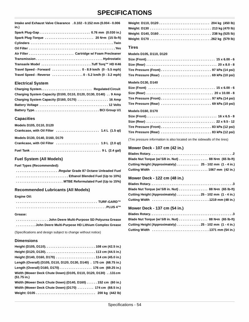
SPECIFICATIONS
Intake and Exhaust Valve Clearance . 0.102 - 0.152 mm (0.004 - 0.006 in.)Spark Plug-Gap . . . . . . . . . . . . . . . . . . . . . . . . . . . . 0.76 mm (0.030 in.)
Spark Plug-Torque . . . . . . . . . . . . . . . . . . . . . . . . . . . 20 N•m (15 lb-ft)
Cylinders . . . . . . . . . . . . . . . . . . . . . . . . . . . . . . . . . . . . . . . . . . . . . . Twin
Oil Filter . . . . . . . . . . . . . . . . . . . . . . . . . . . . . . . . . . . . . . . . . . . . . . . . Yes
Air Filter . . . . . . . . . . . . . . . . . . . . . . . . . Cartridge w/ Foam Precleaner
Transmission . . . . . . . . . . . . . . . . . . . . . . . . . . . . . . . . . . . . . Hydrostatic
Transaxle Model . . . . . . . . . . . . . . . . . . . . . . . . . . . .Tuff Torq™ HD K46
Travel Speed - Forward . . . . . . . . . . . . . . . . 0 - 8.9 km/h (0 - 5.5 mph)
Travel Speed - Reverse . . . . . . . . . . . . . . . . . 0 - 5.2 km/h (0 - 3.2 mph)
Electrical SystemCharging System. . . . . . . . . . . . . . . . . . . . . . . . . . . . Regulated Circuit
Charging System Capacity (D100, D110, D120, D130, D140) . . 9 Amp
Charging System Capacity (D160, D170) . . . . . . . . . . . . . . . . . 16 Amp
Battery Voltage . . . . . . . . . . . . . . . . . . . . . . . . . . . . . . . . . . . . . . 12 Volts
Battery Type. . . . . . . . . . . . . . . . . . . . . . . . . . . . . . . . . . . . BCI Group U1
Capacities
Models D105, D110, D120
Crankcase, with Oil Filter . . . . . . . . . . . . . . . . . . . . . . . . 1.4 L (1.5 qt)
Models D130, D140, D160, D170
Crankcase, with Oil Filter . . . . . . . . . . . . . . . . . . . . . . . . 1.9 L (2.0 qt)
Fuel Tank . . . . . . . . . . . . . . . . . . . . . . . . . . . . . . . . . . . . . . . 9 L (2.4 gal)
Fuel System (All Models)
Fuel Types (Recommended):
. . . . . . . . . . . . . . . . . . . . . . . .Regular Grade 87 Octane Unleaded Fuel
. . . . . . . . . . . . . . . . . . . . . . . . . . . . . Ethanol Blended Fuel (Up to 10%)
. . . . . . . . . . . . . . . . . . . . . . . . . . MTBE Reformulated Fuel (Up to 15%)
Recommended Lubricants (All Models)
Engine Oil:
. . . . . . . . . . . . . . . . . . . . . . . . . . . . . . . . . . . . . . . . . . . . . TURF-GARD™
. . . . . . . . . . . . . . . . . . . . . . . . . . . . . . . . . . . . . . . . . . . . . . . . . . PLUS 4™
Grease:
. . . . . . . . . . . . . . . . . . John Deere Multi-Purpose SD Polyurea Grease
. . . . . . . . . . . John Deere Multi-Purpose HD Lithium Complex Grease
(Specifications and design subject to change without notice)
DimensionsHeight (D105, D110). . . . . . . . . . . . . . . . . . . . . . . . . . . . 108 cm (42.5 in.)
Height (D120, D130). . . . . . . . . . . . . . . . . . . . . . . . . . . . 113 cm (44.5 in.)
Height (D140, D160, D170) . . . . . . . . . . . . . . . . . . . . . . 114 cm (45.0 in.)
Length (Overall) (D105, D110, D120, D130, D140) . 175 cm (68.75 in.)
Length (Overall) D160, D170) . . . . . . . . . . . . . . . . . . 176 cm (69.25 in.)
Width (Mower Deck Chute Down) (D105, D110, D120, D130) . .131 cm (51.75 in.)
Width (Mower Deck Chute Down) (D140, D160) . . . . . . 152 cm (60 in.)
Width (Mower Deck Chute Down) (D170) . . . . . . . . . 174 cm (68.5 in.)
Weight: D105 . . . . . . . . . . . . . . . . . . . . . . . . . . . . . . . . . 200 kg (442 lb)
Weight: D110, D120 . . . . . . . . . . . . . . . . . . . . . . . . . . . . 204 kg (450 lb)
Weight: D130 . . . . . . . . . . . . . . . . . . . . . . . . . . . . . . . . . . 213 kg (470 lb)
Weight: D140, D160 . . . . . . . . . . . . . . . . . . . . . . . . . . . . . 238 kg (525 lb)
Weight: D170 . . . . . . . . . . . . . . . . . . . . . . . . . . . . . . . . . .262 kg (579 lb)
Tires
Models D105, D110, D120
Size (Front) . . . . . . . . . . . . . . . . . . . . . . . . . . . . . . . . . . . . . . 15 x 6.00 - 6
Size (Rear) . . . . . . . . . . . . . . . . . . . . . . . . . . . . . . . . . . . . . . . 20 x 8.0 - 8
Tire Pressure (Front) . . . . . . . . . . . . . . . . . . . . . . . . . . . . 97 kPa (14 psi)
Tire Pressure (Rear) . . . . . . . . . . . . . . . . . . . . . . . . . . . . 69 kPa (10 psi)
Models D130, D140
Size (Front) . . . . . . . . . . . . . . . . . . . . . . . . . . . . . . . . . . . . . 15 x 6.00 - 6
Size (Rear) . . . . . . . . . . . . . . . . . . . . . . . . . . . . . . . . . . . . . 20 x 10.00 - 8
Tire Pressure (Front) . . . . . . . . . . . . . . . . . . . . . . . . . . . . 97 kPa (14 psi)
Tire Pressure (Rear) . . . . . . . . . . . . . . . . . . . . . . . . . . . . 69 kPa (10 psi)
Models D160, D170
Size (Front) . . . . . . . . . . . . . . . . . . . . . . . . . . . . . . . . . . . . . . . 16 x 6.5 - 8
Size (Rear) . . . . . . . . . . . . . . . . . . . . . . . . . . . . . . . . . . . . . . 22 x 9.5 - 12
Tire Pressure (Front) . . . . . . . . . . . . . . . . . . . . . . . . . . . . 83 kPa (12 psi)
Tire Pressure (Rear) . . . . . . . . . . . . . . . . . . . . . . . . . . . . 83 kPa (12 psi)
(Tire pressure information is also located on the sidewalls of the tires)
Mower Deck - 107 cm (42 in.)Blades Rotary. . . . . . . . . . . . . . . . . . . . . . . . . . . . . . . . . . . . . . . . . . . . . .2
Blade Nut Torque (w/ 5/8 in. Nut) . . . . . . . . . . . . . . . . 88 N•m (65 lb-ft)
Cutting Height (Approximately) . . . . . . . . . . . . 25 - 102 mm (1 - 4 in.)
Cutting Width . . . . . . . . . . . . . . . . . . . . . . . . . . . . . . . 1067 mm (42 in.)
Mower Deck - 122 cm (48 in.)Blades Rotary. . . . . . . . . . . . . . . . . . . . . . . . . . . . . . . . . . . . . . . . . . . . . .3
Blade Nut Torque (w/ 5/8 in. Nut) . . . . . . . . . . . . . . . . 88 N•m (65 lb-ft)
Cutting Height (Approximately) . . . . . . . . . . . . . 25 - 102 mm (1 - 4 in.)
Cutting Width . . . . . . . . . . . . . . . . . . . . . . . . . . . . . . . .1219 mm (48 in.)
Mower Deck - 137 cm (54 in.)Blades Rotary. . . . . . . . . . . . . . . . . . . . . . . . . . . . . . . . . . . . . . . . . . . . . .3
Blade Nut Torque (w/ 5/8 in. Nut) . . . . . . . . . . . . . . . . 88 N•m (65 lb-ft)
Cutting Height (Approximately) . . . . . . . . . . . . . 25 - 102 mm (1 - 4 in.)
Cutting Width . . . . . . . . . . . . . . . . . . . . . . . . . . . . . . . .1371 mm (54 in.)
Specifications - 54
WARRANTY
WarrantyProduct WarrantyProduct warranty is provided as part of John Deere’s support program for customers who operate and maintain their equipment as described in this manual.
Engine related warranties stated in this manual refer only to emissions-related parts and components of your engine. The complete engine warranty, less emission-related parts and components, is provided separately as the “Limited Warranty for New John Deere Equipment”.
California and U.S. EPA Emissions Control System Warranty Statement (Off-Road Gas Engines)Your Warranty Rights and Obligations
The California Air Resources Board, John Deere, and the United States Environmental Protection Agency are pleased to explain the emissions control system’s warranty on your model year 2013 or 2014 spark ignited off-road engine equipment. In California, new equipment that uses small or large (less than 1 liter) spark ignited off-road engines must be designed, built and equipped to meet the State’s stringent anti-smog standards. John Deere must warrant the emissions control system on your spark ignited off-road engine equipment for the period listed below provided there has been no abuse, neglect or improper maintenance of your equipment.
Your emissions control system may include parts such as: carburetors or fuel-injection system, ignition system, catalytic converters, fuel tanks, valves, filters, clamps, connectors, and other associated components. Also included may be hoses, belts, sensors and other emission-related assemblies.
Where a warrantable condition exists, John Deere will repair your spark ignited off-road engine equipment at no cost to you including diagnosis, parts and labor.
Manufacturer’s Warranty Coverage:
This emissions control system is warranted for two years. If any emissions related part on your equipment is defective, the part will be repaired or replaced by John Deere.
Owner’s Warranty Responsibilities:
• As the spark ignited off-road equipment owner, you are responsible for the performance of the required maintenance listed in your Operator’s Manual. John Deere recommends that you retain all receipts covering maintenance on your spark ignited off-road engine equipment, but John Deere can not deny warranty solely for lack of receipts or for your failure to ensure the performance of all scheduled maintenance.
• As the spark ignited off-road engine equipment owner, you should however be aware that John Deere may deny you warranty coverage if your spark ignited off-road equipment or a part has failed due to abuse, neglect, or improper maintenance or unapproved modifications.
• You are responsible for presenting your spark ignited off-road engine equipment to an authorized John Deere Turf and Utility retailer as soon as a problem exists. The warranty repairs should be completed in a reasonable amount of time, not to exceed 30 days. If you have a question regarding your warranty coverage, you should contact your John Deere Turf and Utility retailer, or the John Deere Customer Contact Center at 1-800-537-8233, or e-mail John Deere from www.Deere.com.
General Emissions Warranty Coverage:
The warranty period begins on the date the equipment is delivered to an ultimate purchaser. John Deere warrants to the ultimate purchaser and each subsequent purchaser that the spark ignited off-road engine equipment is:
• Designed, built and equipped so as to conform to all applicable regulations adopted by the California Air Resources Board;
•Designed, built and equipped so as to conform at the time of sale with
applicable U.S. Environmental Protection Agency regulations under 40 CFR Parts 1054 and 1060: and,
• Free from defects in materials and workmanship which cause such engine to fail to conform with applicable regulations for a period of two years of engine use from the date of sale to the ultimate purchaser.
Emissions Warranty Interpretation
• Any warranted part that is not scheduled for replacement as required by the maintenance instructions in the Operator’s Manual is warranted for two years. If any such part fails during the period of warranty coverage it will be repaired or replaced by John Deere. Any such part repaired or replaced under warranty is warranted for the remaining warranty period.
• Any warranted part that is scheduled only for regular inspection in the maintenance instructions in the Operator’s Manual is warranted for two years. A statement in the Operator’s Manual to the effect of “repair or replace as necessary” does not reduce the period of warranty coverage. Any such part repaired or replaced under warranty is warranted for the remaining warranty period.
• Any warranted part that is scheduled for replacement as required maintenance in the Operator’s Manual is warranted for the period of time prior to the first scheduled replacement point for that part. If the part fails prior to the first scheduled replacement, the part will be repaired or replaced by John Deere. Any such part repaired or replaced under warranty is warranted for the remainder of the period prior to the first scheduled replacement point for the part.
• Repair or replacement of any warranted part under the warranty will be performed at no charge to the owner at any authorized John Deere Turf and Utility retailer.
• The owner will not be charged for diagnostic labor which leads to the determination that a warranted part is defective, provided such work is performed by John Deere.
• John Deere will repair damages to other engine components proximately caused by a failure under warranty of any emissions-related warranted part.
• Add-on or modified parts that are not exempted by the California Air Resources Board may not be used. The use of any non-exempted add-on or modified parts will be grounds for disallowing a warranty claim. John Deere will not be liable to warrant failures of warranted parts caused by the use of a non-exempted add-on or modified part.
Emission Warranty Parts List
Coverage under this warranty extends only to the parts listed below (the emissions control system parts) to the extent these parts were on the engine and equipment purchased.
Fuel Metering System:
• Carburetor and internal parts (or fuel injection system).
• Air/fuel ratio feedback and control system.
• Cold start enrichment system.
Evaporative System:
• Fuel tank, fuel cap and tether.
• Fuel hose, line, fittings, clamps.
• Fuel pump, fuel shut-off valve.
• Fuel vapor hoses, fittings.
• Carbon canister.
• Rollover/slant valve for fuel vapor control.
• Purge and vent line.
Air Induction System:
• Air cleaner
• Intake manifold.
Warranty - 55
WARRANTY
Ignition System:• Spark plugs.
• Magneto or electronic ignition system.
• Spark advance/retard system.
Exhaust System:
• Exhaust manifold.
• Catalyst muffler.
Miscellaneous Items Used in Above Systems
• Vacuum and temperature switches.
• Electronic controls.
• Hoses, belts, connectors and assemblies.
Limited Liability
a) The liability of John Deere under this Emissions Control System Warranty is limited solely to the remedying of defects in materials or workmanship. This warranty does not cover inconvenience or loss of use of the non-road equipment or engine or transportation of the equipment or engine to or from the John Deere Turf and Utility retailer. John Deere shall not be liable for any other expense, loss, or damage, whether direct, incidental, consequential (except as listed above under “coverage”) or exemplary arising in connection with the sale or use of or inability to use the non-road equipment or engine for any other purpose.
b) No express emissions control system warranty is given by John Deere with respect to the equipment and engine except as specifically set forth in this document. Any emissions control system warranty implied by law, including any warranty of merchantability or fitness for a particular purpose, is expressly limited to the emissions control system warranty terms set forth in this document.
c) No dealer is authorized to modify this Federal, California and John Deere Emissions Control System Warranty.
Tire WarrantyJohn Deere warranty applies for tires available through the John Deere parts system. For tires not available through the John Deere parts system, the tire manufacturer’s warranty applicable to your machine may not apply outside the U.S. (See your John Deere dealer for specific information.)
Limited Battery Warranty
NOTE: Applicable in North America only. For complete machine warranty, reference a copy of the John Deere warranty statement. Contact your John Deere dealer to obtain a copy.
TO SECURE WARRANTY SERVICE
The purchaser must request warranty service from a John Deere dealer authorized to sell John Deere batteries, and present the battery to the dealer with the top cover plate codes intact.
FREE REPLACEMENT
Any new battery which becomes unserviceable (not merely discharged) due to defects in material or workmanship within 90 days of purchase will be replaced free of charge. Installation costs will be covered by warranty if (1) the unserviceable battery was installed by a John Deere factory or dealer, (2) failure occurs within 90 days of purchase, and (3) the replacement battery is installed by a John Deere dealer.
PRO RATA ADJUSTMENT
Any new battery which becomes unserviceable (not merely discharged) due to defects in material or workmanship more than 90 days after purchase, but before the expiration of the applicable adjustment period, will be replaced upon payment of the battery’s current list price less a pro rata credit for unused months of service. The applicable adjustment period
is determined from the Warranty Code printed at the top of the battery and chart below. Installation costs are not covered by warranty after 90 days from the date of purchase.
THIS WARRANTY DOES NOT COVER
A. Breakage of the container, cover, or terminals.
B. Depreciation or damage caused by lack of reasonable and necessary maintenance or by improper maintenance.
C. Transportation, mailing, or service call charges for warranty service.
LIMITATION OF IMPLIED WARRANTIES AND PURCHASER’S REMEDIES
To the extent permitted by law, neither John Deere nor any company affiliated with it makes any warranties, representations, or promises as to the quality, performance or freedom from defect of the products covered by this warranty. IMPLIED WARRANTIES OF MERCHANTABILITY AND FITNESS FOR A PARTICULAR PURPOSE, TO THE EXTENT APPLICABLE, SHALL BE LIMITED IN DURATION TO THE APPLICABLE ADJUSTMENT PERIOD SET FORTH HERE. THE PURCHASER’S ONLY REMEDIES IN CONNECTION WITH THE BREACH OR PERFORMANCE OF ANY WARRANTY ON JOHN DEERE BATTERIES ARE THOSE SET FORTH HERE. IN NO EVENT WILL THE DEALER, JOHN DEERE OR ANY COMPANY AFFILIATED WITH JOHN DEERE BE LIABLE FOR INCIDENTAL OR CONSEQUENTIAL DAMAGES. (Note: Some states do not allow limitations on how long an implied warranty lasts or the exclusion or limitation of incidental or consequential damages. So these limitations and exclusions may not apply to you.) This warranty gives you specific legal rights, and you may also have some rights which vary from state to state.
NO DEALER WARRANTY
The selling dealer makes no warranty of it’s own and the dealer has no authority to make any representation or promise on behalf of John Deere, or to modify the terms or limitations of this warranty in any way.
PRO RATA MONTHS OF ADJUSTMENT
NOTE: If your battery is not labeled with a warranty code, it is a warranty code B.
Warranty Code Warranty Period
A 40 Months
B 36 Months
C 24 Months
Warranty - 56
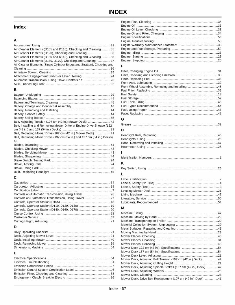
INDEX
Index
AAccessories, Using ................................................................................ 31Air Cleaner Elements (D105 and D110), Checking and Cleaning ......... 35Air Cleaner Elements (D120), Checking and Cleaning .......................... 36Air Cleaner Elements (D130 and D140), Checking and Cleaning ......... 35Air Cleaner Elements (D160, D170), Checking and Cleaning ............... 37Air Cleaner Elements (Single Cylinder Briggs and Stratton), Checking and Cleaning ................................................................................................. 36Air Intake Screen, Cleaning ................................................................... 35Attachment Engagement Switch or Lever, Testing ................................ 24Automatic Transmission, Using Travel Controls on ............................... 26Axle, Lubricating Front ........................................................................... 32
BBagger, Unplugging ............................................................................... 29Balancing Blades ................................................................................... 44Battery and Terminals, Cleaning ........................................................... 45Battery, Charge and Connect at Assembly ............................................ 16Battery, Removing and Installing ........................................................... 44Battery, Service Safely .......................................................................... 44Battery, Using Booster ........................................................................... 45Belt, Adjusting Tension (107 cm (42 in.) Mower Deck) .......................... 42Belt, Installing and Removing Mower Drive at Engine Drive Sheave (122 cm (48 in.) and 137 (54 in.) Decks) ....................................................... 39Belt, Replacing Mower Drive (107 cm (42 in.) Mower Deck) ................. 41Belt, Replacing Mower Drive (137 cm (54 in.) and 137 cm (54 in.) Decks) 42Blades, Balancing .................................................................................. 44Blades, Checking Mower ....................................................................... 43Blades, Servicing Mower ....................................................................... 43Blades, Sharpening ............................................................................... 44Brake Switch, Testing Park .................................................................... 24Brake, Testing Park ............................................................................... 24Brake, Using Park .................................................................................. 25Bulb, Replacing Headlight ..................................................................... 45
CCapacities .............................................................................................. 54Carburetor, Adjusting ............................................................................. 38Certification Label .................................................................................... 7Controls on Automatic Transmission, Using Travel ............................... 26Controls on Hydrostatic Transmission, Using Travel ............................. 27Controls, Operator Station (D105) ......................................................... 18Controls, Operator Station (D110, D120, D130) .................................... 19Controls, Operator Station (D140, D160, D170) .................................... 20Cruise Control, Using ............................................................................. 28Customer Service .................................................................................. 57Cutting Height, Adjusting ....................................................................... 21
DDaily Operating Checklist ...................................................................... 21Deck, Adjusting Mower Level ................................................................ 21Deck, Installing Mower ........................................................................... 40Deck, Removing Mower ......................................................................... 39Dimensions, Machine ............................................................................ 54
EElectrical Specifications ......................................................................... 54Electrical Troubleshooting ..................................................................... 51Emission Compliance Period ................................................................... 7Emission Control System Certification Label ........................................... 6Emission Filter, Checking and Cleaning ................................................ 38Engagement Clutch, Break In Electric ................................................... 16
Engine Fins, Cleaning ............................................................................35Engine Oil ...............................................................................................33Engine Oil Level, Checking ....................................................................33Engine Oil and Filter, Changing .............................................................34Engine Specifications .............................................................................53Engine Troubleshooting .........................................................................50Engine Warranty Maintenance Statement ..............................................33Engine and Fuel Storage, Preparing ......................................................52Engine, Idling .........................................................................................26Engine, Starting ......................................................................................26Engine, Stopping ....................................................................................26
FFilter, Changing Engine Oil ....................................................................34Filter, Checking and Cleaning Emission .................................................38Filter, Replacing Fuel .............................................................................38Front Axle, Lubricating ...........................................................................32Front Wheel Assembly, Removing and Installing ...................................48Fuel Filter, Replacing .............................................................................38Fuel Safety .............................................................................................13Fuel Storage ...........................................................................................52Fuel Tank, Filling ....................................................................................46Fuel Types Recommended ....................................................................54Fuel, Using Proper .................................................................................46Fuse, Replacing .....................................................................................46
GGrease ...................................................................................................32
HHeadlight Bulb, Replacing ......................................................................45Headlights, Using ...................................................................................25Hood, Removing and Installing ..............................................................47Hourmeter, Using ...................................................................................25
IIdentification Numbers ..............................................................................1KKey Switch, Using ..................................................................................25
LLabel, Certification ...................................................................................7Labels, Safety (No Text) ...........................................................................4Labels, Safety (Text) ................................................................................3Leveling Mower Deck .............................................................................21Lifting Machine .......................................................................................47Literature, Service ..................................................................................56Lubricants, Recommended ....................................................................54
MMachine, Lifting ......................................................................................47Machine, Moving by Hand ......................................................................29Machine, Transporting on Trailer ...........................................................29Material Collection System, Unplugging .................................................29Metal Surfaces, Repairing and Cleaning ................................................48Moving Machine by Hand .......................................................................29Mower Blades, Checking ........................................................................43Mower Blades, Choosing .......................................................................31Mower Blades, Servicing ........................................................................43Mower Deck 122 cm (48 in.), Specifications ..........................................54Mower Deck 137 cm (54 in.), Specifications ..........................................54Mower Deck Level, Adjusting .................................................................21Mower Deck, Adjusting Belt Tension (107 cm (42 in.) Deck) .................42Mower Deck, Adjusting Cutting Height ...................................................21Mower Deck, Adjusting Spindle Brakes (107 cm (42 in.) Deck) .............42Mower Deck, Adjusting Wheels ..............................................................23Mower Deck, Cleaning ...........................................................................28Mower Deck, Drive Belt Replacement (107 cm (42 in.) Deck) ...............41
Index - 57
GETTING QUALITY SERVICE
Mower Deck, Drive Belt Replacement (122 cm (48 in.) and 137 cm (54 in.) Decks) .................................................................................................... 42Mower Deck, Engaging and Disengaging .............................................. 28Mower Deck, Installing Deck ................................................................. 40Mower Deck, Lubricating Pivot Points ................................................... 32Mower Deck, Removing Deck ............................................................... 39Mower Deck, Removing and Installing Drive Belt at Engine Sheave (122 cm (48 in.) and 137 (54 in.) Decks) ....................................................... 39Mower Deck, Specifications (107 cm (42 in.) ........................................ 54Mower Deck, Unplugging ....................................................................... 29Mower Troubleshooting ......................................................................... 51Mowing Tips ........................................................................................... 31OOMGX22464J6 ........................................................................................ 0Oil Level, Checking Engine .................................................................... 33Oil and Filter, Changing Engine ............................................................. 34Oil, Engine ............................................................................................. 33Operating Checklist, Daily ..................................................................... 21Operator Station Controls (D105) .......................................................... 18Operator Station Controls (D110, D120, D130) ..................................... 19Operator Station Controls (D140, D160, D170) ..................................... 20
PPark Brake, Testing ............................................................................... 24Park Brake, Testing Switch .................................................................... 24Park Brake, Using .................................................................................. 25Parts Catalog ......................................................................................... 56Parts, Replacement ............................................................................... 56Plastic And Painted Surfaces, Avoid Damage To .................................. 21Plastic Surfaces, Cleaning ..................................................................... 48
RRear Wheel Assembly, Removing and Installing ................................... 49Reverse Implement Option, Testing ...................................................... 25Reverse Implement Option, Using the ................................................... 27
SSafety Label Location (No Text) .............................................................. 4Safety Label Location (Text) .................................................................... 3Safety Systems, Testing ........................................................................ 24Safety, Tire ............................................................................................ 13Seat Switch, Testing .............................................................................. 24Seat, Adjusting ....................................................................................... 21Service Intervals .................................................................................... 32Service Literature ................................................................................... 56Service Reminder, Using ....................................................................... 25Sharpening Blades ................................................................................ 44Spark Arrestor, Using .............................................................................. 9Spark Plug, Checking ............................................................................ 38Specifications ......................................................................................... 53Specifications, 107 cm (42 in.) Mower Deck .......................................... 54Spindle Brakes 107 cm (42 in.) Mower Deck, Adjusting ........................ 42Stablizer, Using Proper Fuel .................................................................. 46Stopping Engine .................................................................................... 26Storage, Preparing Fuel and Engine for ................................................ 52Storage, Preparing Machine for ............................................................. 52Storage, Removing Machine from ......................................................... 52Storing Safety ........................................................................................ 52
TTechnical Manual ................................................................................... 56Testing Safety Systems ......................................................................... 24Tire Chains, Using ................................................................................. 30Tire Pressure, Checking ........................................................................ 47Tire Specifications ................................................................................. 54Tractor Troubleshooting ......................................................................... 51Transmission, Checking (See your John Deere dealer) ........................ 39
Transporting Machine on Trailer ............................................................29Travel Controls on Hydrostatic Transmission, Using .............................27Troubleshooting Chart ............................................................................50
WWarranty Maintenance Statement, Engine .............................................33Warranty Registration, Refer to the Production Identification Section .....2Warranty, Product ..................................................................................55Wash Port, Using ...................................................................................28Weights, Using .......................................................................................30Wheel Assembly, Removing and Installing Front ...................................48Wheel Assembly, Removing and Installing Rear ...................................49Wheels, Adjusting Mower Deck ..............................................................23
Getting Quality ServiceService LiteratureIf you would like a copy of the Parts Catalog or Technical Manual for this machine call:
• U.S. & Canada: 1-800-522-7448.
• All Other Regions: Your John Deere dealer.
PartsWe recommend John Deere quality parts and lubricants, available at your John Deere dealer.
When you order parts, your John Deere dealer needs the serial number or product identification number (PIN) for your machine or attachment. These are the numbers that you recorded in the Product Identification section of this manual.
Order Service Parts Online
Visit http://JDParts.deere.com for your Internet connection to parts ordering and information.
John Deere Quality Continues with Quality ServiceJohn Deere provides a process to handle your questions or problems, should they arise, to ensure that product quality continues with your John Deere dealer’s parts and service support.
Follow the steps below to get answers to any questions you may have about your product.
1. Refer to the appropriate attachment, machine or equipment operator manuals.
2. Contact your John Deere dealer with unanswered questions.
3. In North America or Canada, call the John Deere Customer Contact Center.
• Call 1-800-537-8233 and provide product serial number and model number.
Getting Quality Service - 58

SERVICE RECORD
Service RecordRecord Service Dates
Oil Change Oil Filter Change (If Equipped)
Lubricate Machine
Air Cleaner Element Check/Clean
Fuel Filter Change
Service Record - 59

SERVICE RECORD
Service Record - 60

SERVICE RECORD
Service Record - 61