Embed Size (px)
Citation preview
HOFFMANN
Instrumentos Eletrônicos Ltda
[email protected] www.hfn-br.com
Document Number: 1-005-M001
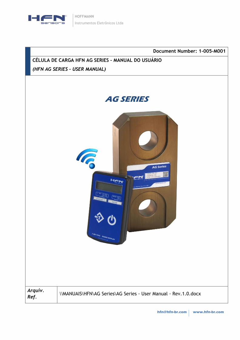
CÉLULA DE CARGA HFN AG SERIES – MANUAL DO USUÁRIO
(HFN AG SERIES – USER MANUAL)
AG SERIES
Arquiv.
Ref. \\MANUAIS\HFN\AG Series\AG Series - User Manual - Rev.1.0.docx
User Manual – AG Series/BD-1943 Page 2 of 21
HISTÓRICO DE REVISÕES
Revisão Descrição
0.0 Primeira Edição
1.0 Revisão 1: BD-1943 Guia Rapido
CHANGE DESCRIPTION
Revision Change Description
0.0 First Edition
1.0 Revision 1: BD-1943 Quick Guide

User Manual – AG Series/BD-1943 Page 3 of 21
ÍNDICE
MANUAL DO USUÁRIO – PORTUGUÊS ........................................................................................... 5
1 INSTRUÇÕES DE SEGURANÇA ................................................................................................. 5
2 CONDIÇÕES DA INSTALAÇÃO NO LOCAL DE USO..................................................................... 7
2.1 PRESSÃO AMBIENTE ....................................................................................................................... 7
2.2 CONDIÇÕES AMBIENTAIS ................................................................................................................. 7
2.3 INFORMAÇÕES ESPECIAIS ................................................................................................................. 7
2.4 PROIBIÇÃO DE PRÓPRIAS MODIFICAÇÕES ............................................................................................. 7
2.5 PESSOAL QUALIFICADO .................................................................................................................... 8
2.6 PREVENÇÃO DE ACIDENTES .............................................................................................................. 8
3 INSTRUÇÕES DE MONTAGEM ................................................................................................. 8
3.1 APLICAÇÃO DA CARGA .................................................................................................................... 9
4 INSTALAÇÃO DAS BATERIAS ................................................................................................... 9
4.1 CÉLULA DE CARGA AG SERIES .......................................................................................................... 9
4.2 INDICADOR BD-1943 ............................................................................................................... 10
4.3 CUIDADO COM AS PILHAS .............................................................................................................. 10
5 OPERAÇÃO .......................................................................................................................... 11
5.1 BD-1943 – GUIA RÁPIDO ......................................................................................................... 11
6 ESPECIFICAÇÕES ................................................................................................................... 13
USER MANUAL (ENGLISH) ........................................................................................................... 14
1 SAFETY INSTRUCTIONS ......................................................................................................... 14
2 CONDITIONS AT THE SITE INSTALLATION .............................................................................. 16
2.1 AMBIENT PRESSURE ...................................................................................................................... 16
2.2 ENVIRONMENTAL CONDITIONS ....................................................................................................... 16
2.3 SPECIAL INFORMATION .................................................................................................................. 16
2.4 PROHIBITION OF OWN CONVERSIONS AND MODIFICATIONS ................................................................... 16

User Manual – AG Series/BD-1943 Page 4 of 21
2.5 QUALIFIED PERSONNEL .................................................................................................................. 16
2.6 ACCIDENT PREVENTION ................................................................................................................. 17
3 MOUNTING INSTRUCTIONS .................................................................................................. 17
3.1 LOAD INTRODUCTION.................................................................................................................... 17
4 INSTALLING THE BATTERIES ................................................................................................. 18
4.1 AG SERIES LOAD CELL .................................................................................................................. 18
4.2 BD-1943 RADIO DISPLAY ............................................................................................................. 18
4.3 PRECAUTIONS FOR BATTERIES ......................................................................................................... 19
5 OPERATION ......................................................................................................................... 19
5.1 BD-1943 – QUICK GUIDE ......................................................................................................... 19
6 SPECIFICATIONS ................................................................................................................... 21

User Manual – AG Series/BD-1943 Page 5 of 21
MANUAL DO USUÁRIO – PORTUGUÊS
1 INSTRUÇÕES DE SEGURANÇA
Nos casos em que a ruptura do equipamento possa causar danos pessoais ou danos ao
equipamento, o usuário deve tomar medidas apropriadas de segurança (tais como
proteção contra quedas, proteção contra sobrecarga, etc.). Para uma operação segura e
livre de contratempos, as células de carga devem ser corretamente transportadas,
armazenadas, e instaladas, e também devem ser cuidadosamente operadas e
inspecionadas.
É fundamental agir de acordo com as normas de prevenção de acidentes em vigor. Em
particular, é extremamente necessário o respeito às cargas limites indicadas nas
especificações (Limite de Carga Estática e Dinâmica).
Use de acordo com os regulamentos
Por uma questão de segurança, a célula de carga só deve ser operada como descrito nas
Instruções de Montagem. Também é fundamental observar as normas legais e de
segurança adequadas para a aplicação em que se destina. O mesmo aplica-se ao uso de
acessórios.
O funcionamento adequado e seguro da célula de carga requer transporte adequado,
correto armazenamento, montagem e operação adequadas e manutenção/inspeção
cuidadosa.
Perigos em geral devido à não-observação das Instruções de Segurança
A instalação inadequada de células de carga, ou operação por pessoas sem treinamento,
podem dar origem a riscos residuais.
Todas as pessoas envolvidas com a instalação, comissionamento, manutenção ou reparo de
uma célula de carga deve ter lido e compreendido as instruções de montagem e, em
particular, as instruções técnicas de segurança.
Riscos Residuais
O escopo de fornecimento e desempenho das células de carga abrangem apenas uma
pequena área da tecnologia de pesagem. Além disso, os projetistas de equipamentos,
instaladores e operadores devem planejar, executar e responder às considerações de
engenharia de segurança da tecnologia de pesagem, de tal forma a minimizar os riscos
User Manual – AG Series/BD-1943 Page 6 of 21
residuais. Regulamentos em vigor devem ser respeitadas em todos os momentos. Deve
haver referência aos riscos residuais relacionados à tecnologia de pesagem.
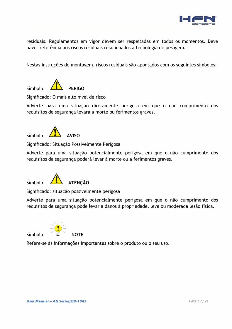
Nestas instruções de montagem, riscos residuais são apontados com os seguintes símbolos:
Símbolo: PERIGO
Significado: O mais alto nível de risco
Adverte para uma situação diretamente perigosa em que o não cumprimento dos
requisitos de segurança levará a morte ou ferimentos graves.
Símbolo: AVISO
Significado: Situação Possivelmente Perigosa
Adverte para uma situação potencialmente perigosa em que o não cumprimento dos
requisitos de segurança poderá levar à morte ou a ferimentos graves.
Símbolo: ATENÇÃO
Significado: situação possivelmente perigosa
Adverte para uma situação potencialmente perigosa em que o não cumprimento dos
requisitos de segurança pode levar a danos à propriedade, leve ou moderada lesão física.
Símbolo: NOTE
Refere-se às informações importantes sobre o produto ou o seu uso.

User Manual – AG Series/BD-1943 Page 7 of 21
2 CONDIÇÕES DA INSTALAÇÃO NO LOCAL DE USO
2.1 Pressão Ambiente
A pressão ambiente para o uso de células de carga pode situar-se entre 0 e 5 bar. Por
favor, note que as mudanças de pressão pode mudar o sinal de saída de referência (zero).
2.2 Condições Ambientais
Todos os materiais que liberam íons de cloro, vai atacar todos os tipos de aço inoxidável,
alumínio e regiões com solda.
Nesses casos, o operador deve tomar as medidas de segurança adequadas.
2.3 Informações Especiais
As células de cargas AG Series são produzidas com alumínio classe aeronáutico, com
proteção anticorrosiva (anodização ou pintura eletrostática).
O operador deve testar a resistência às condições ambientais agressivas, em cada caso
individual.
O uso indevido, como o contato direto da célula de carga com superfícies ásperas, pode
danificar a camada de proteção, expondo o material da célula de carga à corrosão.
ATENÇÃO
Este equipamento contém peças de alta precisão. Portanto, evite temperaturas extremas,
evite a queda ou colisão do equipamento e proteja-o de produtos químicos e sujeira.
O usuário deve testar o equipamento sob condições ambientais agressivas para cada caso
individual.
Choque, impacto ou sobrecarga pode danificar o equipamento permanentemente.
2.4 Proibição de próprias modificações
A célula de carga não deve ser modificada a partir do ponto de vista do projeto de
engenharia e segurança, exceto com o consentimento expresso da Hoffmann. Qualquer
alteração deve excluir toda e qualquer responsabilidade por parte da Hoffmann, por
quaisquer danos decorrentes.
User Manual – AG Series/BD-1943 Page 8 of 21
2.5 Pessoal qualificado
Células de carga devem apenas ser instaladas por pessoas qualificadas, com estrita
conformidade com os dados técnicos e com as normas e regulamentos de segurança que se
seguem. Também é fundamental observar as normas legais e de segurança adequadas para
a aplicação em uso. O mesmo aplica-se ao uso de acessórios.
Pessoal qualificado significa as pessoas encarregadas da instalação, montagem,
comissionamento e operação do produto e que possuem as qualificações adequadas para a
sua função.
2.6 Prevenção de acidentes
Mesmo que a carga máxima de ruptura seja algumas vezes superior à capacidade nominal
do equipamento, faz-se necessário seguir e respeitar todos os regulamentos de prevenção
de acidentes dos órgãos competentes, e nunca utilizar as células de carga com cargas
superiores aos limites estabelecidos para aplicações estáticas e dinâmicas.
3 INSTRUÇÕES DE MONTAGEM
ATENÇÃO
Manuseie a célula de carga com cuidado.
As superfícies de montagem da célula de carga devem estar absolutamente limpas.
Não permitir o acúmulo de poeira, sujeira e outras partículas, pois afetam a
mobilidade da célula de carga e, portanto, mascarando o valor medido. Usar uma
placa de cobertura para proteger a célula de carga de influências mecânicas externas.
Não sobrecarregue as células de carga (por exemplo, por cargas desigualmente
distribuídos, se necessário, fornecer proteção contra sobrecarga (por exemplo,
suportes).
Cada célula de carga deve ser aterrada por um cabo de cobre trançado (aprox. 16
mm2) durante ou imediatamente após a instalação, a fim de evitar quaisquer
correntes de fuga ou sobre corrente que possam fluir através da célula de carga.
User Manual – AG Series/BD-1943 Page 9 of 21
3.1 Aplicação da Carga
PERIGO
As células de carga AG medem forças de tensão na direção longitudinal. Duas manilhas
instaladas em cada um dos olhais da célula de carga são necessárias para aplicação da
força de tração.
As manilhas devem estar devidamente centralizadas e alinhadas. Utilize acessórios de
movimentação de carga adequados nas manilhas.
NÃO UTILIZE A CÉLULA DE CARGA SEM A MANILHA CORRETA!
4 INSTALAÇÃO DAS BATERIAS
4.1 Célula de Carga AG Series
Remova os dois parafusos do compartimento da bateria. Insira duas pilhas AA alcalinas.
Coloque a tampa do compartimento da bateria.
ATENÇÃO: Aperte os parafusos corretamente (Torque ~ 1 Nm) para garantir a
vedação adequada.
O modulo de transmissão é ligado imediatamente após a inserção das baterias. As luzes de
indicação piscam quando o modulo esteja em modo de transmissão.
O indicador BD-1943 deve estar dentro do alcance da antena para ligar ou desligar o
módulo da célula de carga.
É recomendado manter o indicador BD-1943 mais próximo possível da célula de carga para
ligar ou desligar o módulo.
ATENÇÃO: Os módulos de transmissão da célula de carga e indicador não são
protegidos contra inversão de polaridade. Nunca instale as baterias invertidas!
User Manual – AG Series/BD-1943 Page 10 of 21
4.2 INDICADOR BD-1943
Insira duas pilhas AA alcalinas no compartimento de baterias. Recoloque a tampa do
compartimento da bateria, apertando os parafusos corretamente (Torque ~ 0,2 Nm) para
garantir a vedação adequada.
O indicador liga imediatamente após a inserção das pilhas. Para desligar basta manter
pressionada a tecla de alimentação até que o display mostre “Busy”, e então liberá-lo.
A tecla de alimentação do indicador BD-1943 é utilizada também para ligar ou desligar a
célula de carga.
4.3 Cuidado com as Pilhas
ATENÇÃO:
• Use apenas o tipo e tamanho das baterias recomendadas na especificação.
• Ao instalar as baterias, observe a polaridade (+/-). A instalação incorreta da bateria
pode causar danos irreversíveis aos instrumentos.
• Não misture tipos diferentes de pilhas (Ex.: Alcalina com zinco-carbono ou pilhas novas
com as antigas).
• Se não estiver usando o equipamento por um longo período de tempo, retire as pilhas
para evitar danos devido a um possível vazamento da bateria. É altamente recomendado
remover as baterias depois de cada uso, e/ou antes de colocar o equipamento na caixa de
transporte.
• Não descarte as baterias no fogo. Elas podem explodir ou vazar fluido.
• Limpe os contatos da bateria e o dispositivo antes de instalar as baterias.
User Manual – AG Series/BD-1943 Page 11 of 21
5 OPERAÇÃO
5.1 BD-1943 – GUIA RÁPIDO
TECLAS
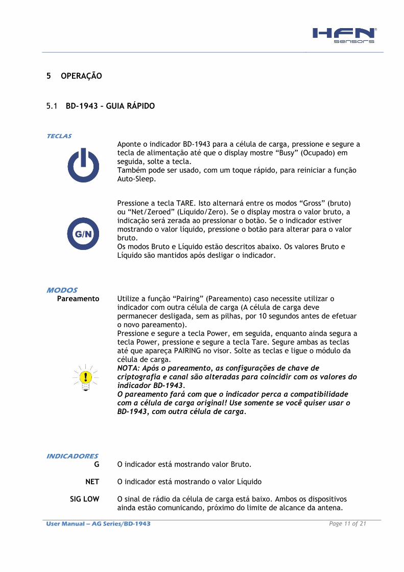
Aponte o indicador BD-1943 para a célula de carga, pressione e segure a tecla de alimentação até que o display mostre “Busy” (Ocupado) em seguida, solte a tecla. Também pode ser usado, com um toque rápido, para reiniciar a função Auto-Sleep.
Pressione a tecla TARE. Isto alternará entre os modos “Gross” (bruto) ou “Net/Zeroed” (Líquido/Zero). Se o display mostra o valor bruto, a indicação será zerada ao pressionar o botão. Se o indicador estiver mostrando o valor líquido, pressione o botão para alterar para o valor bruto. Os modos Bruto e Líquido estão descritos abaixo. Os valores Bruto e Líquido são mantidos após desligar o indicador.
MODOS
Pareamento
Utilize a função “Pairing” (Pareamento) caso necessite utilizar o indicador com outra célula de carga (A célula de carga deve permanecer desligada, sem as pilhas, por 10 segundos antes de efetuar o novo pareamento). Pressione e segure a tecla Power, em seguida, enquanto ainda segura a tecla Power, pressione e segure a tecla Tare. Segure ambas as teclas até que apareça PAIRING no visor. Solte as teclas e ligue o módulo da célula de carga. NOTA: Após o pareamento, as configurações de chave de criptografia e canal são alteradas para coincidir com os valores do indicador BD-1943. O pareamento fará com que o indicador perca a compatibilidade com a célula de carga original! Use somente se você quiser usar o BD-1943, com outra célula de carga.
INDICADORES
G O indicador está mostrando valor Bruto.
NET O indicador está mostrando o valor Líquido
SIG LOW O sinal de rádio da célula de carga está baixo. Ambos os dispositivos ainda estão comunicando, próximo do limite de alcance da antena.
User Manual – AG Series/BD-1943 Page 12 of 21
Assim que o indicador perder a comunicação com a célula de carga, aparecerá “------------“ no visor. Nota: mesmo com baixo sinal de rádio, o indicador mostra os valores corretamente, sem erros de leitura.
BATT LOW As pilhas no indicador estão fracas e devem ser substituídas
REMOTE ERROR
O modulo da célula de carga possui um erro que o indicador não reconhece.
REMOTE BATT LOW
A bateria da célula de carga está baixa
ERRORS
Mostrados no Indicador
Error 1 Um dispositivo externo ativou o modulo de calibração Shunt.
Error 2 Erro de integridade de entrada. O módulo da célula de carga tem um problema de comunicação com os sensores. Pode haver circuitos abertos ou curtos. Em vez de exibir uma leitura enganosa esse erro será exibido.
Overload A carga aplicada à célula de carga ultrapassou o limite máximo permitido.
PERIGO NUNCA ULTRAPASSE OS LIMITES PERMISSÍVEIS DE CARGA ESTÁTICA E DINÂMICA ESPECIFICADOS
User Manual – AG Series/BD-1943 Page 13 of 21
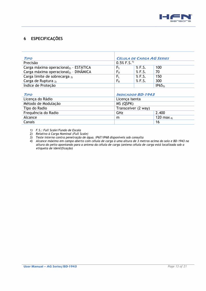
6 ESPECIFICAÇÕES
TIPO
CÉLULA DE CARGA AG SERIES
Precisão 0.5% F.S.1)
Carga máxima operacional2) – ESTÁTICA Carga máxima operacional2) – DINÂMICA
FS FD
% F.S. % F.S.
100 70
Carga limite de sobrecarga 2) Carga de Ruptura 2)
FL FB
% F.S. % F.S.
150 300
Índice de Proteção IP653)
TIPO
INDICADOR BD-1943
Licença do Rádio Licença isenta
Método de Modulação MS (QSPK)
Tipo do Radio Transceiver (2 way)
Frequência do Radio GHz 2.400
Alcance m 120 max 4)
Canais 16
1) F.S.: Full Scale/Fundo de Escala 2) Relativo à Carga Nominal (Full Scale) 3) Teste interno contra penetração de água. IP67/IP68 disponíveis sob consulta 4) Alcance máximo em campo aberto com célula de carga à uma altura de 3 metros acima do solo e BD-1943 na
altura do peito apontando para a antena da célula de carga (antena célula de carga está localizada sob a etiqueta de identificação)

User Manual – AG Series/BD-1943 Page 14 of 21
USER MANUAL (ENGLISH)
1 SAFETY INSTRUCTIONS
In cases where a breakage would cause injury to persons or damage to equipment, the
user must take appropriate safety measures (such as fall protection, overload protection,
etc.). For safe and trouble free operation, the load cell must not only be correctly
transported, stored, sited and installed but must also be carefully operated and
maintained.
It is essential to comply with the relevant accident prevention regulations. In particular,
you should take into account the limit loads quoted in the specifications.
Use in accordance with the regulations
In the interests of safety, the load cell should only be operated as described in the
Mounting Instructions. It is also essential to observe the appropriate legal and safety
regulations for the application concerned during use. The same applies to the use of
accessories.
The load cell is not safety element within the meaning of its use as intended.
Proper and safe operation of this load cell requires proper transportation, correct storage,
assembly and mounting and careful operation and maintenance.
General dangers due to non-observance of the safety instructions
The load cell can give rise to residual dangers if it is inappropriately installed and
operated by untrained personnel.
Everyone involved with the installation, commissioning, maintenance or repair of a force
transducer must have read and understood the Mounting Instructions and in particular the
technical safety instructions.
Residual dangers
The scope of supply and performance of the load cells covers only a small area of
weighing technology. In addition, equipment planners, installers and operators should
plan, implement and respond to the safety engineering considerations of weighing
technology in such a way as to minimize residual dangers. Prevailing regulations must be
User Manual – AG Series/BD-1943 Page 15 of 21
complied with at all times. There must be reference to the residual dangers connected
with weighing technology.
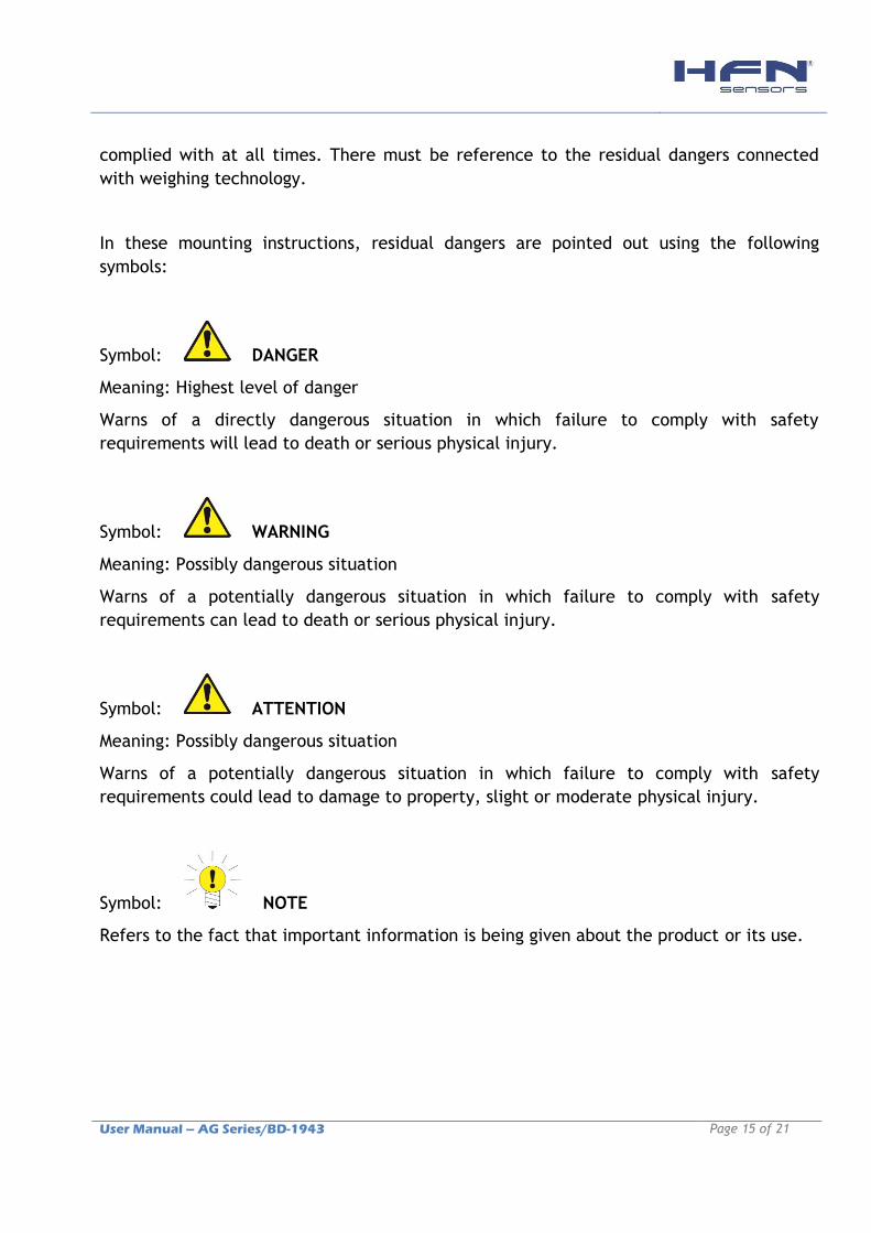
In these mounting instructions, residual dangers are pointed out using the following
symbols:
Symbol: DANGER
Meaning: Highest level of danger
Warns of a directly dangerous situation in which failure to comply with safety
requirements will lead to death or serious physical injury.
Symbol: WARNING
Meaning: Possibly dangerous situation
Warns of a potentially dangerous situation in which failure to comply with safety
requirements can lead to death or serious physical injury.
Symbol: ATTENTION
Meaning: Possibly dangerous situation
Warns of a potentially dangerous situation in which failure to comply with safety
requirements could lead to damage to property, slight or moderate physical injury.
Symbol: NOTE
Refers to the fact that important information is being given about the product or its use.
User Manual – AG Series/BD-1943 Page 16 of 21
2 CONDITIONS AT THE SITE INSTALLATION
2.1 Ambient pressure
The ambient pressure for transducers may be between 0 and 5 bar. Please note that
pressure changes may shift the zero output signal.
2.2 Environmental conditions
In the context of your application, please note that all materials, which release chlorine
ions, will attack all grades of stainless steel and their welding seams.
In such cases, the operator must take appropriate safety measures.
2.3 Special information
HFN® AG Series load cell are produced from high quality aluminum with Anti-Corrosive
protection. The user must test for resistance to aggressive environmental conditions in
each individual case.
Misuse, as direct contact of the load cell with rough surfaces, damage the Anti-Corrosive
protection, exposing the equipment to corrosion.
ATTENTION
This equipment contains high-precision parts. Therefore, avoid extreme temperatures,
avoid drop or bump the equipment and protect it from chemicals and dirt.
Shock, impact and overload damage the equipment permanently.
2.4 Prohibition of own conversions and modifications
The load cell must not be modified from the design or safety engineering point of view
except with our express agreement. Any modification shall exclude all liability on our part
for any damage resulting therefrom.
2.5 Qualified personnel
This load cell is only to be installed by qualified personnel strictly in accordance with the
technical data and with the safety rules and regulations which follow. It is also essential
to observe the appropriate legal and safety regulations for the application concerned. The
same applies to the use of accessories.

User Manual – AG Series/BD-1943 Page 17 of 21
Qualified personnel means persons entrusted with the installation, fitting, commissioning
and operation of the product who possess the appropriate qualifications for their function.
2.6 Accident prevention
Although the specified nominal capacity in the destructive range is several times the full
scale value, the relevant accident prevention regulations from the trade associations must
be taken into consideration.
3 MOUNTING INSTRUCTIONS
ATTENTION
Handle the transducer carefully.
The transducer seating must be horizontal, even and, together with the transducer
mounting surface, it must be absolutely clean.
Dust, dirt and other particles are not to accumulate such that they affect the load
cell’s mobility and thus falsify the measured value. Use a cover plate to protect the
load cell from external mechanical influences.
Do not overload the transducers (e.g. by unevenly distributed loads; if necessary,
provide overload protection (e.g. supports).
Each transducer should be shunted by a stranded copper cable (approx. 16 mm2)
during or immediately after installation, in order to prevent any welding or lightning
currents flowing through the transducer.
3.1 Load introduction
DANGER
The AG Series Load Cells measure tension loads in the longitudinal direction. Two shackles
installed on both eyes are provided for the application of tensile loads.
The shackles must be properly centered and aligned. Use proper cargo handling
accessories in shackles.
DO NOT USE THE LOAD CELL WITHOUT THE CORRECT SHACKLES SPECIFIED!

User Manual – AG Series/BD-1943 Page 18 of 21
4 INSTALLING THE BATTERIES
4.1 AG Series Load Cell
Remove the two screws on the rear battery compartment. Insert two alkaline AA
batteries. Refit the battery compartment cover.
ATTENTION: Tighten the screws properly (Torque ~ 1 N.m) to ensure proper
sealing.
The load cell module is now switched on. The indication light flashes when the radio
module is at the transmitting mode.
The BD-1943 handheld must be on limit of the antenna range to wake the load cell radio
up or to turn it off/sleep mode.
It is recommended to maintain the BD-1943 handheld as close as possible to the load cell
in order to turn it off. Make sure that the indication light flashes goes off before packing
the load cell.
ATTENTION: The radio module is not reverse polarity protected! Use only the
correct batteries! Never install the batteries reversed!
4.2 BD-1943 Radio Display
Insert two alkaline AA batteries on the hear battery compartment. Refit the battery
compartment cover, tightening the screws properly (Torque ~ 0.2 N.m) to ensure proper
sealing.
The handheld device is now switched on so should be turned off until the load cell module
is ready. To turn off just hold down the power key until the display shows BUSY then
release it.
The BD-1943 is used to turn the load cell on/off by pressing the power button.
User Manual – AG Series/BD-1943 Page 19 of 21
4.3 Precautions for batteries
ATTENTION:
• Use only the type and size of recommended batteries in the specification.
• When installing batteries, observe the correct polarity (+/-). Incorrect installation of
battery can cause irreversible damage to the unit.
• Do not mix different types of batteries (Ex .: alkaline with zinc-carbon, or new batteries
with old ones).
• If not using the equipment for a long period of time, remove the batteries to prevent
damage due to possible battery leakage. It is highly recommended to remove the batteries
after each use, and/or prior to pack the equipment.
• Do not dismiss the batteries in fire. They may explode or leak fluid.
• Clean the battery contacts and the device before installing the batteries.
5 OPERATION
5.1 BD-1943 – QUICK GUIDE
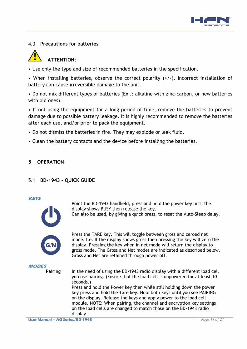
KEYS
Point the BD-1943 handheld, press and hold the power key until the display shows BUSY then release the key. Can also be used, by giving a quick press, to reset the Auto-Sleep delay.
Press the TARE key. This will toggle between gross and zeroed net mode. I.e. If the display shows gross then pressing the key will zero the display. Pressing the key when in net mode will return the display to gross mode. The Gross and Net modes are indicated as described below. Gross and Net are retained through power off.
MODES
Pairing In the need of using the BD-1943 radio display with a different load cell you use pairing. (Ensure that the load cell is unpowered for at least 10 seconds.) Press and hold the Power key then while still holding down the power key press and hold the Tare key. Hold both keys until you see PAIRING on the display. Release the keys and apply power to the load cell module. NOTE: When pairing, the channel and encryption key settings on the load cells are changed to match those on the BD-1943 radio display.

User Manual – AG Series/BD-1943 Page 20 of 21
NOTE: Pairing can lose the compatibility with the original load cell! Use only if you want to use the BD-1943 with another load cell.
INDICATORS
G The display is showing Gross weight.
NET The display is showing Net weight.
SIG LOW The radio signal from load cell is low. The device is still functioning but the limit of the range may be near. Communications may start to deteriorate when this indicator is visible. Until ------ is displayed the communications is still OK and the display can be relied on for accuracy. Note: Even with a degraded signal the display value will always be correct.
BATT LOW The batteries in the handheld are low and need to be replaced.
REMOTE ERROR
The load cell module has an error that the handheld does not recognize.
REMOTE BATT LOW
The battery or supply to the load cell module is low.
ERRORS
Displayed on handheld LCD.
Error 1 An external device has placed the load cell module in Shunt Calibration mode so rather than display a misleading reading this error is displayed instead.
Error 2 Input integrity error. The load cell module has found a problem with the input. There may be open or short circuits. Rather than display a misleading reading this error is displayed instead.
Overload The load applied to the load cell reached the maximum permissible value.
Symbol: DANGER NEVER OPERATE THE LOAD CELL OVER THE STATIC AND DYNAMIC LIMITS!
User Manual – AG Series/BD-1943 Page 21 of 21
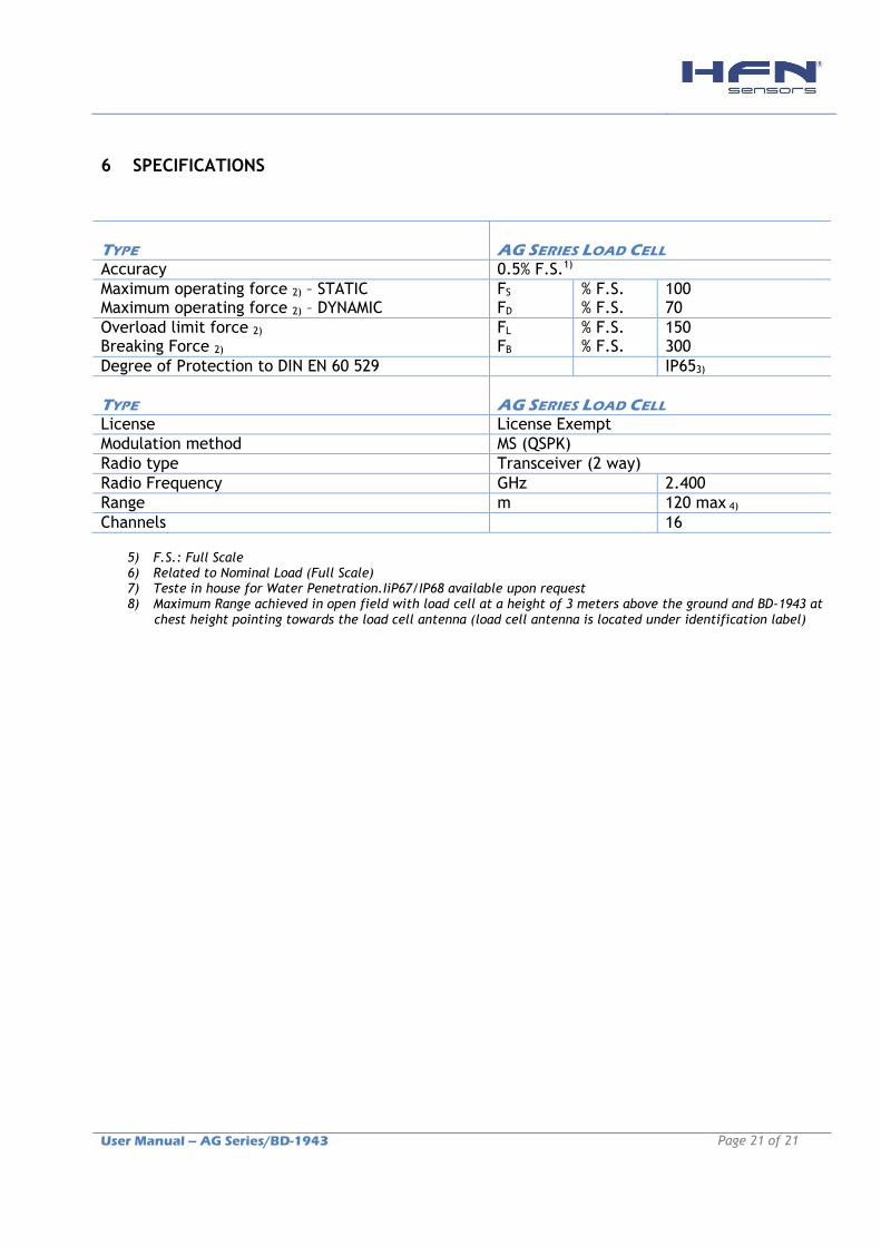
6 SPECIFICATIONS
TYPE
AG SERIES LOAD CELL
Accuracy 0.5% F.S.1)
Maximum operating force 2) – STATIC Maximum operating force 2) – DYNAMIC
FS FD
% F.S. % F.S.
100 70
Overload limit force 2) Breaking Force 2)
FL FB
% F.S. % F.S.
150 300
Degree of Protection to DIN EN 60 529 IP653)
TYPE
AG SERIES LOAD CELL
License License Exempt
Modulation method MS (QSPK)
Radio type Transceiver (2 way)
Radio Frequency GHz 2.400
Range m 120 max 4)
Channels 16
5) F.S.: Full Scale 6) Related to Nominal Load (Full Scale) 7) Teste in house for Water Penetration.IiP67/IP68 available upon request 8) Maximum Range achieved in open field with load cell at a height of 3 meters above the ground and BD-1943 at
chest height pointing towards the load cell antenna (load cell antenna is located under identification label)