Embed Size (px)
Citation preview

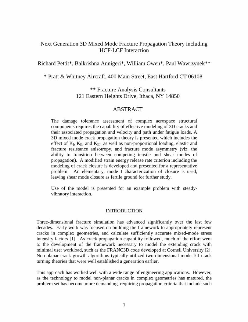
AFRL-RX-WP-TP-2010-4048
NEXT GENERATION 3D MIXED MODE FRACTURE PROPAGATION THEORY INCLUDING HCF-LCF INTERACTION (PREPRINT) Richard Pettit, Balkrishna Annigeri, and William Owen Pratt & Whitney Aircraft Paul Wawrzynek Fracture Analysis Consultants
JANUARY 2010
Approved for public release; distribution unlimited. See additional restrictions described on inside pages
STINFO COPY
AIR FORCE RESEARCH LABORATORY MATERIALS AND MANUFACTURING DIRECTORATE
WRIGHT-PATTERSON AIR FORCE BASE, OH 45433-7750 AIR FORCE MATERIEL COMMAND
UNITED STATES AIR FORCE

i
REPORT DOCUMENTATION PAGE Form Approved
OMB No. 0704-0188
The public reporting burden for this collection of information is estimated to average 1 hour per response, including the time for reviewing instructions, searching existing data sources, gathering and maintaining the data needed, and completing and reviewing the collection of information. Send comments regarding this burden estimate or any other aspect of this collection of information, including suggestions for reducing this burden, to Department of Defense, Washington Headquarters Services, Directorate for Information Operations and Reports (0704-0188), 1215 Jefferson Davis Highway, Suite 1204, Arlington, VA 22202-4302. Respondents should be aware that notwithstanding any other provision of law, no person shall be subject to any penalty for failing to comply with a collection of information if it does not display a currently valid OMB control number. PLEASE DO NOT RETURN YOUR FORM TO THE ABOVE ADDRESS.
1. REPORT DATE (DD-MM-YY) 2. REPORT TYPE 3. DATES COVERED (From - To)
January 2010 Journal Article Preprint 01 January 2010 – 31 January 2010 4. TITLE AND SUBTITLE
NEXT GENERATION 3D MIXED MODE FRACTURE PROPAGATION THEORY INCLUDING HCF-LCF INTERACTION (PREPRINT)
5a. CONTRACT NUMBER
FA8650-04-C-5200 5b. GRANT NUMBER
5c. PROGRAM ELEMENT NUMBER
62102F 6. AUTHOR(S)
Richard Pettit, Balkrishna Annigeri, and William Owen (Pratt & Whitney Aircraft) Paul Wawrzynek (Fracture Analysis Consultants)
5d. PROJECT NUMBER
4347 5e. TASK NUMBER
RG 5f. WORK UNIT NUMBER
M02R3000 7. PERFORMING ORGANIZATION NAME(S) AND ADDRESS(ES) 8. PERFORMING ORGANIZATION
Pratt & Whitney Aircraft 400 Main Street East Hartford, CT 06108
Fracture Analysis Consultants 121 Eastern Heights Drive Ithaca, NY 14850
REPORT NUMBER
9. SPONSORING/MONITORING AGENCY NAME(S) AND ADDRESS(ES)
Air Force Research Laboratory 10. SPONSORING/MONITORING AGENCY ACRONYM(S)
Materials and Manufacturing Directorate Wright-Patterson Air Force Base, OH 45433-7750 Air Force Materiel Command United States Air Force
AFRL/RXLMN 11. SPONSORING/MONITORING AGENCY REPORT NUMBER(S)
AFRL-RX-WP-TP-2010-4048
12. DISTRIBUTION/AVAILABILITY STATEMENT
Approved for public release; distribution unlimited.
13. SUPPLEMENTARY NOTES
Journal article submitted to the ASME Journal of Engineering Materials and Technology. PAO Case Number: 88ABW-2009-4815; Clearance Date: 18 Nov 2009. Paper contains color.
14. ABSTRACT
The damage tolerance assessment of complex aerospace structural components requires the capability of effective modeling of 3D cracks and their associated propagation and velocity and path under fatigue loads. A 3D mixed mode crack propagation theory is presented which includes the effect of KI, KII, and KIII, as well as non-proportional loading, elastic and fracture resistance anisotropy, and fracture mode asymmetry (viz. the ability to transition between competing tensile and shear modes of propagation). A modified strain energy release rate criterion including the modeling of crack closure is developed and presented for a representative problem. An elementary, mode I characterization of closure is used, leaving shear mode closure as fertile ground for further study. Use of the model is presented for an example problem with steady-vibratory interaction.
15. SUBJECT TERMS
damage tolerance, 3D cracks, propagation, velocity
16. SECURITY CLASSIFICATION OF: 17. LIMITATION OF ABSTRACT:
SAR
18. NUMBER OF PAGES
26
19a. NAME OF RESPONSIBLE PERSON (Monitor)
a. REPORT Unclassified
b. ABSTRACT Unclassified
c. THIS PAGE Unclassified
Reji John 19b. TELEPHONE NUMBER (Include Area Code)
N/A
Standard Form 298 (Rev. 8-98) Prescribed by ANSI Std. Z39-18
1
Next Generation 3D Mixed Mode Fracture Propagation Theory including
HCF-LCF Interaction
Richard Pettit*, Balkrishna Annigeri*, William Owen*, Paul Wawrzynek**
* Pratt & Whitney Aircraft, 400 Main Street, East Hartford CT 06108
** Fracture Analysis Consultants
121 Eastern Heights Drive, Ithaca, NY 14850
ABSTRACT
The damage tolerance assessment of complex aerospace structural
components requires the capability of effective modeling of 3D cracks and
their associated propagation and velocity and path under fatigue loads. A
3D mixed mode crack propagation theory is presented which includes the
effect of KI, KII, and KIII, as well as non-proportional loading, elastic and
fracture resistance anisotropy, and fracture mode asymmetry (viz. the
ability to transition between competing tensile and shear modes of
propagation). A modified strain energy release rate criterion including the
modeling of crack closure is developed and presented for a representative
problem. An elementary, mode I characterization of closure is used,
leaving shear mode closure as fertile ground for further study.
Use of the model is presented for an example problem with steady-
vibratory interaction.
INTRODUCTION
Three-dimensional fracture simulation has advanced significantly over the last few
decades. Early work was focused on building the framework to appropriately represent
cracks in complex geometries, and calculate sufficiently accurate mixed-mode stress
intensity factors [1]. As crack propagation capability followed, much of the effort went
to the development of the framework necessary to model the extending crack with
minimal user workload, such as the FRANC3D code developed at Cornell University [2].
Non-planar crack growth algorithms typically utilized two-dimensional mode I/II crack
turning theories that were well established a generation earlier.
This approach has worked well with a wide range of engineering applications. However,
as the technology to model non-planar cracks in complex geometries has matured, the
problem set has become more demanding, requiring propagation criteria that include such

2
things as HCF/LCF interaction, Mixed Non-Proportional Loading (MNPL), fracture
mode asymmetry, and both elastic and fracture resistance anisotropy.
Legacy crack propagation/turning criteria, such as the Maximum Tangential Stress
(MTS) criterion [3], assume proportional loading (KII/KI = constant), and predict crack
growth along KII ≈ 0 path. For non-proportional loading, the relative proportions of KI,
KII, and KIII vary with time throughout the cycle, and there is no path that enforces KII=0
during the entire cycle (not to mention the influence of mode III). Though widely
neglected, MNPL can result from any structural situation wherein steady and cyclic
stresses are misaligned, as in the vibrating blade problem illustrated in Figure 1
Vibrating Rotor Blade Resulting in MNPL .
Steady Spin Load
Vibratory
Load
Steady Spin Load
Vibratory
Load
Figure 1 Vibrating Rotor Blade Resulting in MNPL
In order to enable crack growth simulation for this class of problems, two significant
advances were required.
1. A validated theoretical approach to handle crack growth and trajectory under
MNPL loading.
2. A reduced-order nonlinear dynamics approach to enable FEM vibration modeling
including contact between opposing crack faces.
The current paper will deal exclusively with the first of these requirements, though
promising approaches to the second problem are a separate subject of investigation [4].
Theoretical enhancements have been implemented in the FRANC3D code as described
herein.
Theoretical Background for Crack Growth with Mixed Non-Proportional Loading
Conditions
Maximum Stress Criteria
Resolving the (isotropic) lead crack stress intensities, (KI, KII, KIII), into the asymptotic
stress intensities (kI, kII, kIII) associated with an infinitesimal crack branch at angle , we
obtain

3
2
cos2
1cos3sin2
cos2
12
sin2
3
2cos
2cos2 2
IIIzIII
IIIrII
IIII
Krk
KKrk
KKrk
(1)
For the coordinate system illustrated in Figure 2
T
r
x
y r
r
1
2
x
y
Ki
ki
Figure 2 Reference coordinate system for theoretical development
A similar solution for 3D anisotropy based on the work of Hoenig [5], will not be further
discussed here, but has been be treated and implemented in FRANC3D in much the same
manner as the isotropic theory that will now be further discussed.
For proportional loading, the classical Maximum Tangential Stress (MTS) theory,
proposed by Erdogan and Sih [2] for isotropic materials, asserts that the crack will grow
toward the location of the maximum tangential tensile stress (equivalent to maximizing
kI). By differentiating kI and equating to zero
KII
KI
sinc3cosc 1 (2)
or [6]
)(4
)(811tan2
2
1
III
III
cKK
KK
(3)
where c is the kink angle. This criterion seeks out a mode I crack path. As illustrated
in Figure 3, the maximum tangential stress theory works well for low ductility materials
like PMMA, but fails to predict a transition, observed for 7075-T6 and 2024-T3
aluminum alloys, to a path that is associated with the Maximum Shear Stress (MSS) . In

4
these materials, the transition is sudden, and the crack seems exclusively dominated by
either mode I or mode II.
While it should be noted that the data in Figure 3 is for cracks loaded quasi-statically
until the crack begins to tear, as opposed to cyclic loading, similar behavior can occur as
a result of cyclic loading, as will be shown.
-30
-20
-10
0
10
20
30
40
50
60
70
80
0 10 20 30 40 50 60 70 80 90
Mode mixity, -ATAN(KII/KI)
Dqc
LEFM Max stressAmstutz (1995) 2024-T3, L-TAmstutz (1995) 2024-T3, T-LHallback & Nilsson (1994) 7075-T6Maccagno & Knott (1989), PMMAMaccagno & Knott (1991), HY130 @ -196C
Mode I
Transition
7075-T6
Transition
2024-T3
Mode II
(MSS)
Transition
HY 130 Steel
PMMA, No Transition
(MTS)
Figure 3 Test data of various investigators [7, 8, 9, 10], showing transition to shear mode dominated growth for ductile metals at high mode mixities
Fracture Mode Interaction and Asymmetry
Chao and Liu [11] describe the sharp transition behavior as a result of competing failure
mechanisms in mode I and mode II as shown in Figure 4. According to their hypothesis,
the two modes do not interact (see also [12]), and the crack will fail in Mode I unless
maxmax IIC
II
IC
I
K
k
K
k
(4)
Where KIc and KIIc are the pure mode fracture toughness values for a straight growing
crack, and the subscript “max” denotes maximizing with respect to the kink angle. For
the purpose of further discussion, this criterion will be described as the “Modal” fracture
criterion

5
KII
KI
KIc
KIIc
max Criterion
r max
Criterion
Transit ion
KII/KI
Figure 4 Transition mechanism proposed by Chao and Liu {11]
Note, however, that the HY130 steel in Figure 3 behaves in a different manner1,
exhibiting a more gradual transition to a kink angle of zero, rather than the angle
associated with maximum mode II. Thus, both tensile and shear modes of growth appear
to be contributing to failure. This type of behavior correlates well to a Modified Strain
Energy Release Rate (MSERR) approach proposed by Kfouri & Brown [13], that
suggests a failure locus of the form
1
22
IIC
II
IC
I
K
k
K
k (5)
For a non-critical load state, the most critical crack growth direction would be obtained
by maximizing the left hand side of this equation with regard to . A measure of how
nearly critical the loading is in terms of an equivalent mode I stress intensity can be
written by solving Equations (4) and (5) for KIc respectively and rewriting so that the
crack is critical if kIeq = KIC.
maxmax1 , II
IIC
IC
Ieq kK
KkMAXk (Modal) (6)
max
2
2
2
II
IIC
IC
IeqI kK
Kkk (MSERR) (7)
1 The HY-130 tests exhibited tearing in a zig-zag microscopic shear mode. The crack
turning angles shown for this alloy were read from Maccagno and Knott’s photographs,
and reflect the average trend of the zig-zag line, consistent with our intent. Maccagno
and Knott gave quite different values of the turning angle.

6
While the modal criterion assumes non-interaction of modes I and II, modes II and III are
both shear modes, and can be combined into a resolved shear stress intensity 22
23 IIIII kkk (8)
It seems reasonable to assume that such modes would interact in materials that fail by
either the Modal or MSERR criterion, which infers that equations (6) and (7) can be
generalized in 3D to
max
2
2
2
2
max, III
IIIC
IC
II
IIC
IC
IeqI kK
Kk
K
KkMAXk (9)
(Modal)
and,
max
2
2
2
2
2
III
IIIC
IC
II
IIC
IC
IeqI kK
Kk
K
Kkk (10)
(MSERR)
The ratios KIC/KIIC and KIC/KIIIC are measures of the fracture mode asymmetry of a
material, a term coined by Kfouri describing the relative fracture resistance of a given
material in the different modes. The material dependent transition points observed in the
data in Figure 3 can be correlated to different values of these ratios. While the fracture
mode asymmetry is couched in terms of fracture toughness ratios, the intent is to view
these ratios as material parameters in their own right, that can be used to model the
transitions between tensile and shear crack propagation under both monotonic and cyclic
loading conditions.
Fracture Resistance Anisotropy
In addition to fracture mode asymmetry, which addresses the relative fracture resistance
of a material to the different fracture modes, there is also the potential for the fracture
resistance to vary as a function of crack orientation within the material. Buczeck and
Herakovitch [14] expressed the fracture resistance in 2D as a simple elliptical function.
This was generalized to include a more flexible interpolation function, as shown in Figure
5, and extended to 3D [15, 16, 17] to express the (pure mode) stress intensity factor at
which a crack will propagate in an arbitrary orientation. The crack orientation in 3D is
identified by the normal and tangential vectors (n,a) as illustrated in Figure 6a.

7
n = .3
.5
1
2
0
-1
-1
1
1
Kp(0)
Kp(90)
r =Kp()
Kp(0) = 1
Kp(90) = 1.5
nn
p
n
p
pKK
K
2
1
2
2
2
2
)90(
sin
)0(
cos)(
Figure 5 Polar interpolation function for fracture resistance anisotropy in 2D [16, 17]

8
a
n
Plane Tangent to
Developing Crack at
Crack Front
Crack
Front
a. Geometry of crack orientation at a point on an arbitrary crack front
a
K31
K23
K21
K13
x2
x3
x1
K32
K12
K1(a)
K2(a)
3
2 1
K3(a)
b. Principle fracture resistance values and traces of crack growth direction a in cardinal planes
Figure 6 Physical Parameters Governing 3D Fracture Resistance Anisotropy [15]
Assuming three principle planes of material symmetry, each with their own 2D fracture
resistance interpolation functions as shown in Figure 6b, the stress intensity at which a
crack will propagate in the (n,a) orientation is given by

9
2
1
2
3
2
3
2
2
2
2
2
1
2
1)(
K
n
K
n
K
nK p an, (11)
Where the trace fracture resistance values, Ki of the a vector in fracture resistance space,
as illustrated in Figure 6b, are given by
mm
ik
k
m
ij
j
i
i
K
a
K
a
aK
2
1
2
2
2
2
21
)(
a (non-repeating) (12)
and the Kij are the six principal fracture resistance values in 3D (two for each principal
planes), and ni and ai are the components of the n and a vectors. Depending on
processing symmetries, the six principal fracture resistance values may not all be unique.
If they are all equal, and l m=1, the properties are isotropic with regard to fracture
resistance.
For the purposes of the current development, Kp will be considered to be normalized to
the fracture resistance in a reference orientation, likely chosen to be the orientation for
which the properties are most fully characterized. By definition, Kp=1 in the reference
orientation.
Extension to Fatigue Crack Growth
For application to fatigue crack growth, the six principal fracture resistance parameters
and the fracture mode asymmetry parameters are assumed to be the same for all crack
growth in a given material, whether near threshold or approaching the fracture toughness.
This implicitly assumes that, the Keff
vs da/dN curves are parallel regardless of crack
orientation or modality of failure, and any differences can be represented by an
appropriate horizontal shift (in Kmax and Keff
). While this is almost certainly an
oversimplification, it represents an attempt to include all these real-world effects in the
simplest way possible2.
When we speak of Keff
in this venue, we are referring to the cyclic stress intensity that
actually makes it to the crack tip, as opposed to the globally applied K. Among the
potential crack tip shielding effects, Mode I plasticity induced crack closure [18], though
still a topic of lively discussion, remains an industry standard approach to account for R-
ratio effects. Add shear modes, and there is the potential for friction to reduce the
effective shear cyclic stress intensity. While there is ample evidence for shear mode
crack tip shielding in the literature [19, 20, 21] no quantitative theoretical framework has
become widely accepted for modeling this behavior.
Despite these difficulties, it was recognized that without taking into account shielding
effects in some way, known phenomena could not be predicted. Also, it was desired to at
least maintain industry standard capability for mode I problems, including the ability to
predict the effect of R-ratio. It was thus decided to adopt as a baseline the NASGRO
crack growth model formulation [22, 23], including the Newman closure equations for
2 Kfouri suggested that the fracture mode asymmetry might also be a function of orientation, but that
possibility was excluded in the current formulation.

10
Mode I closure, and attempt to extend the equations in a rudimentary way to account for
mixed modes. While it was recognized that this could potentially have serious
shortcomings, it would serve at least as a temporary member in the overall theoretical
framework, with the opportunity to improve upon it as better methods become available.
For the purposes of the present formulation, we will again invoke the steady-vibratory
scenario of Figure 1, and introduce the notation
KKK (13)
Superscripts refer to the extreme values, max and min, for KI, and to the corresponding
extreme values for the shear modes. That is, the positive sign will correspond to the
extreme load state with the most positive KI value, regardless of the sign or magnitude of
the shear modes.
Referring to Figure 3, there are two possible assumptions that could be made with regard
to crack closure:
-Closure occurs in the lead crack only (no infinitesimal kink, resolved stresses
only)
-Closure behavior occurs in the infinitesimal kink tip
With the assumption of kink tip closure, crack growth is evaluated at the infinitesimal
kink tip, and Eq 13 would written in lower case k’s , and be evaluated (and the sign
convention established) at the kink tip. While capital (lead crack) notation will be
followed on the next few equations, bear in mind that they would be written in lower case
(kink tip) notation for the second assumption above. With that in mind, crack closure
will be defined by the mode I component.
1FKKKK I
op
II
eff
I
(14)
Where Newman and global closure options as shown in Figure 7.
closureglobalfor
closureNewmanfor
kfor
Kif
K
KK
RfF
applied
I
II
0
),min(
)(
1
0
1 (15)
R
Kop/K+
Newman closure
Global closure
Figure 7 Illustration of Newman and global closure
The Newman closure function (slightly modified by the additional material parameter C
for negative R-ratios) is given by

11
0),(/
01/
where
1
/1
3
3
2
21
1
RforRRARARAAMAXSS
RforRCAASS
R
SS
K
KRf
o
op
o
op
op
I
eff
I
(16)
I
I
o
o
o
o
o
o
K
KR
stressflow
strainplane
stressplanefactorconstraint
AAA
AAAA
SA
SA
0.3
0.1
12
1
071.415.
2cos05.34.825.
13
312
1
1
2
While KII and KIII do not “close” in the sense that mode I does, it can first be
postulated that once the kink tip closes in mode I, a “stick” or “slip” condition exists,
altering KII and KIII as follows
frictionslipfor
frictionstickforFF
where
FKK
FKK
III
eff
III
II
eff
II
1
1
23
23
23
(17)
For simple sliding friction, F23 should lie between stick and slip values. For (Newman)
closure over a small region near the tip of the crack, the weight functions for tension and
shear modes are identical, thus the maximum amount of K23 that can be dissipated in
Coulomb friction by a compressive KI is
),0(23 I
op
I
comp
I
comp
I
frict KKMaxKwhereKK (18)
To the degree that the global weight functions for tensile and shear are in agreement,
these expressions will also be approximately true for global closure. Allowing the
possibility of closure at both extremes of the cycle,
frictionCoulombforF
KK
KKMaxF
IIIII
comp
I
comp
I
122
23 ,1
(19)
Note that like the stress intensity factors, the closure parameters F1 and F23 may be
written in lower case when they refer to values evaluated at the kink tip.

12
Lead Crack Closure
The lead crack stress intensity factors and R-ratio for lead crack closure may be
expressed as
vibIII
II
I
stIII
II
I
III
II
I
K
K
K
K
K
K
K
K
K
(20)
I
II
K
KR (21)
The opening stress intensity factors are given by
)(
)(
)(
23
23
1
IIIIII
IIII
II
III
II
I
op
III
op
II
op
I
KKF
KKF
KKF
K
K
K
K
K
K
(22)
In the special case where KI+<0, KI
+ and KI
op must are set to zero for compression-
compression loading. The effective crack tip k values are calculated from the lead K+
and Kop
values using (1).
)]()([
)]()([
)()(
op
IIIIII
op
IIII
op
II
eff
III
eff
II
eff
I
kkabs
kkabs
kk
k
k
k
(23)
It is postulated that the crack will grow in the direction corresponding to the maximum
growth rate, da/dN, associated with these k values, which will require a numerical
search to maximize an appropriate growth parameter. Note that the use of resolved
kIeff
()|max as the crack turning criterion with global closure, proportional loading, and
positive KI values yields results equivalent to the MTS crack turning criterion. A more
general criterion will be proposed later on.
One area of discomfort evident in the foregoing formulation is the treatment of negative
R-ratios. In NASGRO and other legacy codes, negative K’s are nominally allowed, and
act to accelerate the crack growth via negative R-ratios using the Newman closure
equations (an approach with its own shortcomings even for mode I loading). In mixed-
mode situations, however, allowing negative KI values (which unrealistically involves
crack faces passing through each other) leads to resolved mode II components at non-
zero . Yet, neglecting negative KI values neglects the associated acceleration associated
with –R ratios.
Kink Tip Closure
The lead crack stress intensity factors needed to evaluate kink tip closure are the same as
given in Equation (20), except that for the reasons just discussed, in the case of a negative
R-ratio at the lead crack it was found necessary to enforce global closure (truncate
negative KI at zero) on the KI term before evaluating its contribution to mode II at the
kink tip. Negative lead crack KI’s are allowed to contribute to kI, to preserve the negative
R-ratio acceleration for near-mode I scenarios.

13
Theoretically, the sign convention as to which is the + side of the cycle is not decided
until the kink tip stress intensity factors and ranges are calculated from the lead crack
values using (1).
)()(
)()(
)()(
IIIIII
IIII
II
III
II
I
kk
kk
kk
abs
k
k
k
(24)
However, by taking the absolute value and by defining the mode I R-ratio as
),(
),(
II
III
kkMAX
kkMINR (25)
we rectify the use of the lead crack sign convention (as will be seen, the sign of the shear
mode ranges is later squared, and is thus inconsequential). The kink tip effective stress
intensity ranges then given by
III
II
I
eff
III
eff
II
eff
I
kf
kf
kf
k
k
k
23
23
1
(26)
Generalized Crack Propagation Criteria
As alluded to earlier, determination of the crack growth direction will require a numerical
search to maximize an appropriate growth parameter. Following the approach of Buzcek
and Herakovitch [14] used successfully in FRANC2D [24] for many years, the crack is
postulated to grow in the direction so that the ratio between the crack driving force and
the crack growth resistance is maximized.
max
resistencegrowthCrack
forcedrivingCrack (27)
Writing Equations (9, 10) in terms of keff
as crack driving forces, and using (11) for the
crack growth resistance, we can write the generalized crack propagation criteria as
max
2
2
2
2
max
1, eff
III
IIIC
ICeff
II
IIC
IC
pp
eff
Ieff
eqI kK
Kk
K
K
KK
kMAXk (28)
(Modal)
And,
max
2
2
2
2
21
eff
III
IIIC
ICeff
II
IIC
ICeff
I
p
eff
eqI kK
Kk
K
Kk
Kk (29)
(MSERR)
Note that these kI eqeff
values are effective in the sense that they are closure adjusted, and
equivalent in the sense that they include all mixed mode effects (to the extent the theory
is capable), and can thus be used in conjunction with a standard mode I closure model.
The angle resulting from the maximization, c, is the predicted kink angle.

14
Use of the NASGRO Equation
The NASGRO Equation for calculation of the crack growth rate is given as follows [22].
q
c
p
applied
th
beff
eq
K
K
K
K
kCdN
da
max1
1
)( (30)
Where we have taken the liberty of including kI eqeff
and,
01
01
0
1*
1
0
1*
1
1
RforA
fK
RforA
fK
K
NP
N
P
P
RCC
RC
CR
RC
th (31)
0
1
*
1 aa
aKK (32)
ys
ICt
tA
kICC
KtwhereeBKK
k
5.21 0
2
0 (33)
The problem is that Kmax and Kapplied, as required in Equation (30), are not defined in a
manner sufficiently general to include mixed mode behavior. It is proposed that Kmax be
generalized by using the equivalent value.
eqIeqIeqI kkMAXk ,max (34)
Where kI eq can be written for the two material behaviors as
cc
III
IIIC
IC
II
IIC
IC
pp
IeqI k
K
Kk
K
K
KK
kMAXk
2
2
2
2
1, (35)
(Modal)
and,
c
III
IIIC
ICII
IIC
ICI
p
eqI kK
Kk
K
Kk
Kk
2
2
2
2
21 (MSERR) (36)
The Kapplied value to be used to shape the near-threshold regime is more difficult to
define with confidence, in part, because there is some evidence [25 ] that as threshold is
approached (very small scale yielding), the modal transition sometimes disappears
(suggesting that the fracture mode asymmetry ratios reduce near threshold). Based on
this tentative observation, one might simply assume that Kth in Equation (30) is
evaluated using (31) with R= RI, and use kI (calculated with no closure, thus the same
as in (24)) as Kapplied. However, this would require that c be determined by maximizing
(30) instead of (28) or (29). Such an approach might have merit, driving cracks in a
mode I direction near threshold, but could potentially be non-conservative if shear modes

15
were able to contribute to propagation in the near-threshold regime. On the other hand,
one could conservatively neglect threshold altogether.
For the current implementation it was decided to calculate pure mode thresholds as
follows.
th
IKCalculated per NASGRO
model with R=RI
*
1KK
KK
Ic
IIcth
II (37)
*
1KK
KK
Ic
IIIcth
III
The use of the intrinsic (closure-free) thresholds as the basis for estimating shear mode
threshold is almost certainly conservative. The equivalent applied values may then be
calculated.
cc
applied
IIIth
III
th
Iapplied
IIth
II
th
I
pp
applied
Iapplied
eqI kK
Kk
K
K
KK
kCRITk
2
2
2
2
1,
(modal) (38)
c
applied
IIIth
III
th
Iapplied
IIth
II
th
Iapplied
I
p
applied
eqI kK
Kk
K
Kk
Kk
2
2
2
2
21
(MSERR) (39)
KI th
and kI eqapplied
are substituted for kth and kapplied in Equation (30) to calculate
the crack growth rate. This method is not expected to perform well at predicting MPNL
threshold behavior, but should serve as a lower bound for the purposes of crack growth
analyses until a better method becomes available.
Correlation with Tension-Torsion Data
A mixed mode/non-proportional loading test program was undertaken to provide MNPL
crack turning data. Specimens were made of IN718 nickel alloy, machined into a
tension-torsion configuration with through-wall cracks, and thus were predominantly
loaded in mode I/II. Tests included specimens with tension and torsion loading in-phase,
tension constant and cyclic torsion, torsion constant and cyclic tension, and tension and
torsion loading180 degrees out-of-phase. Fabrication and testing took place at NASA
MSFC, and fractography and K-solution development was performed by Shelby
Highsmith [26] at Georgia Tech. A summary of the test data is provided in Table 1.
Some crack tips were observed to bifurcate initially, with one of the kinks subsequently
becoming dominant. In other cases, a negative kink would occur on one crack tip, and a
positive kink on the other (speaking in crack tip coordinates, so a “symmetric” looking
kink arrangement is actually one positive and one negative). In all these cases, both
primary and secondary angles were recorded (though it wasn’t always clear which was

16
which), and when more than one like angle resulted, they were averaged in the table. For
further detail, see [26].
Table 1. Inco 718 Crack Kink angle Data
Measured Kink Angles
Spec No RI RII RIII KI+ KII+ KIII+ Mean Beq Primary Secondary
In Phase 1 0.6 0.6 0.6 19.160 10.280 5.6100 28.22 -37.0
2 0.6 0.6 0.6 19.435 10.670 5.7000 28.77 -37.0
8 0.1 0.1 0.1 10.940 10.830 2.1700 44.71 -38.0 8.5
9 0.1 0.1 0.1 11.025 10.725 2.7600 44.21 -56.5 17
12 0.1 0.1 0.1 16.470 7.170 1.7200 23.53 -28.0
16 0.1 0.1 0.1 13.600 8.850 2.3800 33.05 -32.5
KI Const 3 1 0.6 0.6 17.705 11.090 3.2300 26.33 -54.5
4 1 -1 -1 17.775 11.175 2.5200 0.00 0.0
6 1 0.0204 0.0204 20.405 10.430 6.3750 13.84 4.5
10 1 0.1 0.1 10.445 10.365 2.2000 25.22 1.0
13 1 0.1 0.1 16.130 7.195 1.0650 13.30 -46.5 5.5
KII Const 5 0.6 1 1 21.470 10.755 7.0400 33.23 -16.0
7 0.1 1 1 15.480 15.470 2.4250 64.63 -15.5
11 0.1 1 1 16.240 6.970 1.9600 50.06 -10.5
Out of Phase 17 0.1 10 10 14.130 0.902 0.2770 42.37 -38.0
18 0.1 10 10 9.960 0.964 0.2770 44.81 -64.0 6.0
19 0.1 10 10 16.075 0.691 0.1965 39.68 14.5
The data was fit to an MNPL model that captured modal transition behavior and other
trends quite well, except possibly for the out-of-phase data. Observed crack turning
angles show excellent correlation with the model, as presented in Figure 8. Hollow
symbols represent model predictions, and (neighboring) solid symbols are test data, with
both primary and secondary angles plotted. Note that Highsmith defined the experiments
with shear of opposite sign to the data in Figure 3, resulting in “flipped” plots.

17
-80
-60
-40
-20
0
20
40
60
80
0 15 30 45 60 75 90
[Atan(KII/KI max) +Atan(KII/KI min)]/2
Kin
k A
ngle
MTSMSS(Chao & Liu)In PhaseIn Phase PredictionKI ConstKI Const PredictionKII ConstKII Const PredictionOut of PhaseOut of Phase PredOut of PhaseIn PhaseKI Const
Figure 2.2 Correlation of Mixed-Mode, Non-Proportionally Loaded Specimens Data with Predicted Kink Angles
The ability to correlate the data was encouraging, and fracture surface examination
(Figures 2.2a and 2.2b) showed a striking difference in appearance for tensile and shear
dominated fracture, lending additional credibility to the existence of a fracture mode
transition. On the down side, it was found that the data could be fit fairly comparably
using more than one combination of parameters, which would predict significantly
different growth rates. Unfortunately, crack growth rates were not measured during these
tests, so a unique best fit could not be established for lifing purposes.

18
a. In-phase
b. Constant tension/cyclic torsion
Figure 2.3 Crack Face Appearance for Tensile and Shear Dominated Crack Growth [28]
Discussion
An implementation of an MNPL crack growth approach has been presented capable of
analyzing a constant amplitude linear cycle between two points. While this is an
encouraging advance, significant obstacles remain. Vibratory modes can exhibit
subcycles involving all three fracture modes, particularly when neighboring vibratory
modes are active simultaneously. Inevitably, a real-world application of the method will
require a fully 3D pairing method, which remains to be defined.
Tensile crack (MHS) deflection
= -27 ° Shear crack (MSS) deflection
= 18 °
Shear crack (MSS) deflection
= 1 °
Tensile crack (MHS) deflection
= -41 °

19
Also, evidence from other authors [21,27] suggests that addition of shear modes into an
otherwise mode I dominated cycle can in fact slow or arrest the crack in some regimes, as
opposed to speeding it up as would be predicted with positive fracture mode asymmetry
ratios. Further, Tschegg [20] showed that cracks propagating (planar) in pure mode III
can slow down and arrest even when the applied KIII increases with crack length. As
aluded to earlier, these shortcomings are likely attributable to roughness induced closure
associated with shear mode growth, which is not correctly accounted for by the simple
mode I plasticity induced closure/friction method presented herein. It is nevertheless
hoped that the framework provided will remain useful as further advances remedy these
deficiencies.
Acknowledgment
The authors wish to acknowledge DARPA/USAF funding for the bulk of the theoretical
work under the Prognosis program. Additional theoretical work and implementation was
funded by a USAF sponsored SBIR program. Test data was provided by NASA MSFC
and Georgia Institute of Technology.
References
[1] Need appropriate reference
[2] P. A. Wawrzynek, A. R. Ingraffea, “Interactive Finite-Element Analyses of Fracture
Processes: An Integrated Approach”, Theoretical and Applied Fracture Mechanics, Vol.
8, 1987, pp. 137-150.
[3] F. Erdogan, G. C. Sih; “On the Extension of Plates under Plane Loading and
Transverse Shear”, Journal of Basic Engineering, Vol. 85D, No. 4, pp. 519-527, 1963.
[4] A. Saito, M. Castanier, c. Pierre, O. Podou, “Efficient Nonlinear Vibration Analysis
of the Forced Response of Rotating Cracked Blades”, J. Comput.Nonlinear Dynam., Vol
4, Issue 1, Jan, 2009.
[5] A. Hoenig, “Near-Tip Behavior of a Crack in a Plane Anisotropic Elastic Body”,
Engineering Fracture Mechanics, Vol. 16, No. 3, pp. 3930403, 1982.
[6] G. P. Cherapanov, Mechanics of Brittle Fracture, McGraw-Hill, New York, 1979.
[7] B. E. Amstutz, M. A. Sutton, D. S. Dawicke, and J. C. Newman, “An Experimental
Study of CTOD for Mode I/Mode II Stable Crack Growth in Thin 2024-T3 Aluminum
Specimens”, Fracture Mechanics: 26th Volume, ASTM STP 1256, American Society for
Testing and Materials, pp. 257-271, 1995.
[8] N. Hallback, F. Nilsson, “Mixed-Mode I/II Fracture Behaviour of an Aluminium
Alloy”, Journal of the Mechanics and Physics of Solids, Vol. 42, No. 9, pp. 1345-1374,
1994.
[9] T. M. Maccagno, J. F. Knott, “The Fracture Behaviour of PMMA in Mixed Modes I
and II”, Engineering Fracture Mechanics, Vol. 34, No. 1, pp. 65-86, 1989.
[10] T. M. Maccagno, J. F. Knott, “The Low Temperature Brittle Fracture Behaviour of
Steel in Mixed Modes I and II”, Engineering Fracture Mechanics, Vol. 38, No. 2/3, pp.
111-128, 1991.

20
[11] Y. J. Chao, S. Liu, “On the Failure of Cracks Under Mixed-Mode Loads”,
International Journal of Fracture, Vol. 87, pp. 201-223, 1997.
[12] C. Dalle Donne, H. Doker, “Plane Stress Crack Resistance Curves of an Inclined
Crack Under Biaxial Loading”, Multiaxial Fatigue and Deformation Testing Techniques,
ASTM STP 1280, American Society for Testing and Materials, pp. 243-263, 1997.
[13] A. P. Kfouri, M.W. Brown, “A Fracture Criterion for Cracks Under Mixed-Mode
Loading”, Fatigue & Fracture Mechanics of Engineering Structures & Materials, Vol.
18, No. 9, pp. 959-969, 1995.
[14] M. B. Buczek, C. T. Herakovitch, “A Normal Stress Criterion for Crack Extension
Direction in Orthotropic Composite Materials”, J. Composite Materials, Vol. 19, pp. 544-
533, 1985.
[15] R. G. Pettit, Crack Turning Integrally Stiffened Aircraft Structures, PhD
Dissertation, Cornell University, pp. 61-67, 2000. [16] High Cycle Fatigue (HCF) Life Assurance Methodologies, Annual Technical
Report., Contract No. RSC99009, delivered by Pratt & Whitney to University of Dayton
Research Institute, pp. A-30 to A-50, 15 April, 2001.
[17] R. K. Kersey, D. P. DeLuca, R. G. Pettit, Parametric Study of Fatigue Crack
Threshold and HCF/LCF Interaction in Single Crystal Superalloy, Aeromat 2003.
[18] J. C. Newman, Jr., ”A Crack Opening Stress Equation for Fatigue Crack Growth”,
Int. J. Fract. 24, R131-R135 (1984).
[19] H. Nayeb-Hashemi, F. A. McClintock, R. O. Ritchie, “Effects of Friction and High
Torque on Fatigue Crack Propagation in Mode III”, Metall. Transactions A, Vol 13A, pp.
2197-2204, 1982.
[20] E. K. Tschegg, “Sliding Mode Crack Closure and Mode III Fatigue Crack Growth
in Mild Steel”, Acta Metall., Vol. 31, No. 9, pp. 1323-1330, 1983.
[21] J. P. Campbell, R. O. Ritchie, “Mixed Mode, High-cycle Fatigue-Crack Growth
Thresholds in Ti 6-AL-4V”, Engineering Fracture Mechanics, Vol. 67, pp. 209-249.
[22] NASGRO4 manual. www.nasgro.com
[23] S.C. Forth et al, Fatigue Fract Eng Mat Struct, Vol. 25, pp. 3-15, 2002.
[24] T.J. Boone, P.A. Wawrzynek, A. R. Ingraffea, “Finite Element Modeling of
Fracture Propagation in Orthotropic Materials, Engineering Fracture Mechanics, Vol. 26,
No. 2, pp. 185-201, 1987.
[25] K. Tanaka et al, Fatigue Crack Propagation from a Precrack Under Combined
Torsional and Axial Loading, Fatigue & Fracture of Engng. Mater. Struct., Vol 26, pp.
73-82, 2005.
[26] Highsmith, Shelby, PhD Dissertation. Georgia Institute of Technology, 2009.
[27] Feng et al, International Journal of Fatigue, Vol. 28, pp. 19-27, 2006