Embed Size (px)
Citation preview

AFFORDABLE HOUSING PROJECTHABITAT FOR HUMANITY DESIGN
HAROLD HYTE
TABLE OF CONTENTSProject description
Project planning
Rendering and elevation
Habitat for humanity guidelines
Habitat for humanity features
Building code requirements
Site plan
Dimensioned floor plan
Floor plan
Door window sections
Wall section view
Waste water calculations
Storm water calculations
For Project 2.3.1, we were required to build an affordable house that met the guidelines set out by Habitat for Humanity.
This involved a maximum square footage constraint to ensure the house would be affordable. The maximum size constraint adjusted depending on the number of bedrooms included in the house. Minimum hallway sizes and a ramp were also required to make sure the house would be wheelchair accessible.
The house also had to meet a minimum size requirement as well.
PROJECT DESCRIPTION

PROJECT PLANNINGThese are the design and bubble sketches used to come up with the original plan for the house. The design sketches have a scale where one block = 5 feet, which was used to make sure the house was under the maximum square footage, which it was at 1225 square feet.
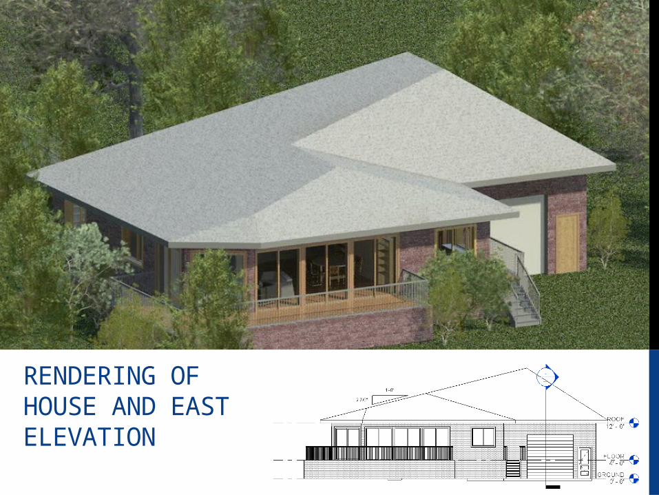
RENDERING OF HOUSE AND EAST ELEVATION
HABITAT FOR HUMANITY GUIDELINESAccording to the guidelines, the house had to be under 1233 square feet as it had 3 bedrooms. In order to meet this requirement, I had to remove several rooms from the original floor plan.
The guidelines also required the inclusion of wheelchair accessibility which I achieved by adding a 48 foot ramp at a 12 degree slope from the house to the sidewalk and making sure all hallways were at least 5 feet wide.
Also according to the guidelines, I added a crawlspace under the house that can be used for storage.
All bedrooms in the house were made emergency accessible through a window and a door in the event of a fire, per the requirements. A utility room was added onto the garage for additional storage as well as placement of the water heater. An open kitchen was also required in the design.
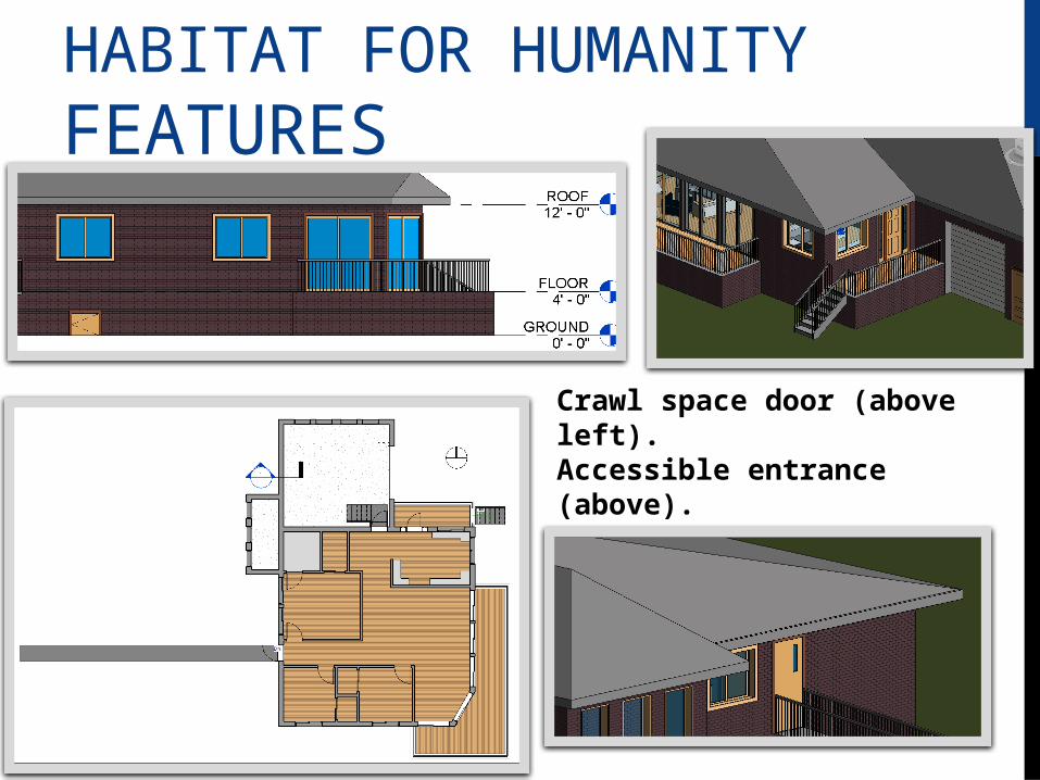
HABITAT FOR HUMANITY FEATURES
Crawl space door (above left).Accessible entrance (above).Ramp (left and below).Open kitchen (left).
BUILDING CODE REQUIREMENTS
All plumbing fixtures are connected to the public water and sewage system already surrounding the lot.
Portable water is supplied to the places of living within the house.
House has an approved water heater that works automatically to not waste water or energy.
The pipes of the house are below the frost line.
Sewer drainage pipe is at a 2% slope.

The site plan set to a scale of 1’’ = 30’ shows the utility lines around the lot, the lot itself, and the house.
SITE PLAN
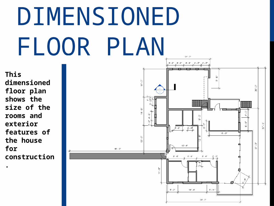
DIMENSIONED FLOOR PLAN
This dimensioned floor plan shows the size of the rooms and exterior features of the house for construction.

FLOOR PLANS
Above is the house shown with furniture in the various rooms and the trees on the lot. On the right are the rooms shown with furniture removed and the various rooms labeled.
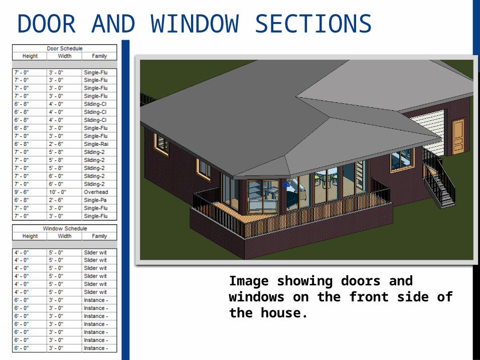
DOOR AND WINDOW SECTIONS
Image showing doors and windows on the front side of the house.
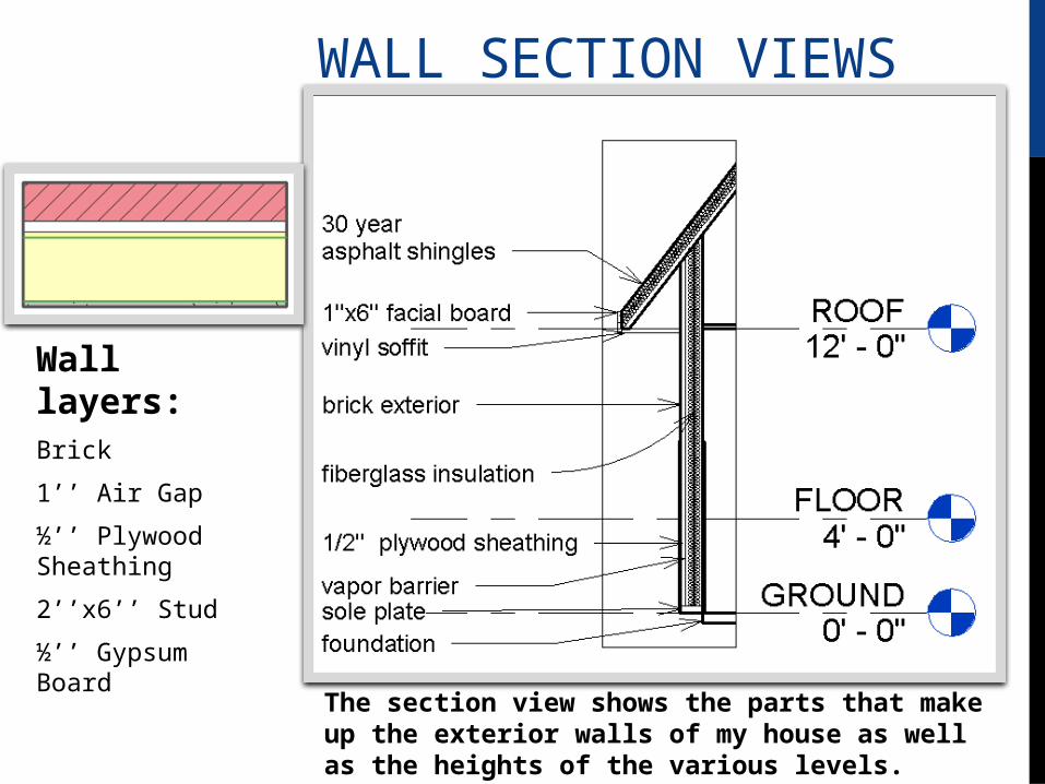
WALL SECTION VIEWS
The section view shows the parts that make up the exterior walls of my house as well as the heights of the various levels.
Wall layers:Brick
1’’ Air Gap
½’’ Plywood Sheathing
2’’x6’’ Stud
½’’ Gypsum Board

STORM WATER CALCULATIONSQ=CiA
C= .95 post - .1 pre
i= 1.3 in/hr (1 year intensity estimate)
A= 2815.73 sq ft (roof area) = 0.0646 acres
18769 sq ft (pre- total lot) = .431 acres
PRE CONSTRUCTION
Q = (.1)(1.3)(0.431)
Q = 0.05603
POST CONSTRUTION
Area of lot except house = .431 - .0646 = 0.3664
Q = (0.95)(1.3)(0.0646)
Q = (0.95)(0.08398)
Q = 0.08398
Q = (0.1)(1.3)(0.3664)
Q = 0.047632
0.047632 + 0.08398 = 0.131612 cfs
FINAL POST CONSTRUCTION RUNOFF =
approximately .132cfs
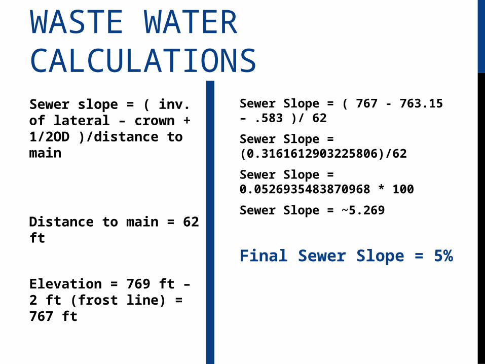
WASTE WATER CALCULATIONSSewer slope = ( inv. of lateral – crown + 1/2OD )/distance to main
Distance to main = 62 ft
Elevation = 769 ft – 2 ft (frost line) = 767 ft
Sewer Slope = ( 767 - 763.15 – .583 )/ 62
Sewer Slope = (0.3161612903225806)/62
Sewer Slope = 0.0526935483870968 * 100
Sewer Slope = ~5.269
Final Sewer Slope = 5%